

Page 1
®
AFL-26/42A-9652 Panel PC
MODEL:
AFL-26/42A-9652
26"/42" Panel PC with Intel
VGA, Dual GbE, CompactFlash®, SATA and PCIe Mini
User Manual
Chipset, 2 GB DDR2
Rev. 1.00 – 31 December, 2008
Page i
Page 2
AFL-26/42A-9652 Panel PC
Revision
Date Version Changes
31 December, 2008 1.00 Initial release
Page ii
Page 3

AFL-26/42A-9652 Panel PC
COPYRIGHT NOTICE
The information in this document is subject to change without prior notice in order to
improve reliability, design and function and does not represent a commitment on the part of
the manufacturer.
In no event will the manufacturer be liable for direct, indirect, special, incidental, or
consequential damages arising out of the use or inability to use the product or
documentation, even if advised of the possibility of such damages.
This document contains proprietary information protected by copyright. All rights are
Copyright
reserved. No part of this manual may be reproduced by any mechanical, electronic, or
other means in any form without prior written permission of the manufacturer.
TRADEMARKS
All registered trademarks and product names mentioned herein are used for identification
purposes only and may be trademarks and/or registered trademarks of their respective
owners.
Page iii
Page 4
AFL-26/42A-9652 Panel PC
Packing List
NOTE:
If any of the components listed in the checklist below are missing,
please do not proceed with the installation. Contact the IEI reseller or
vendor you purchased the AFL-26/42A-9652 from or contact an IEI
sales representative directly. To contact an IEI sales representative,
please send an email to
The items listed below should all be included in the AFL-26/42A-9652 package.
1 x AFL-26/42A-9652
1 x Power cord
1 x Remote control (batteries included)
1 x User’s manual (this document)
1 x Antenna set (for 42” model)
Images of the above items are shown in Chapter 2.
sales@iei.com.tw.
Page iv
Page 5

AFL-26/42A-9652 Panel PC
Table of Contents
1 INTRODUCTION.......................................................................................................... 1
1.1 OVERVIEW.................................................................................................................. 2
1.2 MODEL VARIATIONS................................................................................................... 2
1.3 BENEFITS ................................................................................................................... 3
1.4 STANDARD FEATURES ................................................................................................ 3
1.5 EXTERNAL OVERVIEW................................................................................................ 4
1.5.1 Front Panel........................................................................................................ 4
1.5.2 Rear Panel ......................................................................................................... 5
1.5.3 Bottom Panel...................................................................................................... 6
1.6 INTERNAL OVERVIEW................................................................................................. 7
1.7 SPECIFICATIONS ......................................................................................................... 7
1.8 DIMENSIONS............................................................................................................... 9
1.8.1 26” Dimensions ................................................................................................. 9
1.8.2 42” Dimensions ............................................................................................... 10
2 INSTALLATION ..........................................................................................................11
2.1 UNPACK THE PANEL PC............................................................................................ 12
2.2 PACKING LIST........................................................................................................... 13
2.3 OPTIONAL ITEMS...................................................................................................... 14
2.4 COMPACTFLASH® CARD INSTALLATION.................................................................. 14
2.5 HARD DRIVE INSTALLATION..................................................................................... 15
2.5.1 AFL-26A Internal Hard Drive Installation...................................................... 15
2.5.2 AFL-642A Hard Drive Installation.................................................................. 17
2.6 AT/ATX MODE SELECTION...................................................................................... 18
2.6.1 ATX Power Mode ............................................................................................. 19
2.6.2 AT Power Mode................................................................................................ 19
2.7 MOUNTING THE SYSTEM .......................................................................................... 20
2.8 BOTTOM PANEL CONNECTORS ................................................................................. 20
2.8.1 LAN Connection............................................................................................... 20
2.8.2 Serial Device Connection ................................................................................ 21
2.8.3 USB Device Connection................................................................................... 22
Page v
Page 6

2.8.4 VGA Monitor Connection ................................................................................ 23
2.9 POWER CONNECTION ............................................................................................... 24
2.10 JUMPER SETTINGS.................................................................................................. 25
2.10.1 CompactFlash® Card Setup.......................................................................... 25
2.10.2 COM1 Pin-9 Setup......................................................................................... 26
2.10.3 COM2 Pin-9 Setup......................................................................................... 26
2.10.4 COM3 Pin-9 Setup......................................................................................... 27
2.10.5 COM3 RS-232/422/485 Setup........................................................................ 27
3 BIOS SETUP................................................................................................................ 29
3.1 INTRODUCTION......................................................................................................... 30
3.1.1 Starting Setup................................................................................................... 30
3.1.2 Using Setup...................................................................................................... 30
3.1.3 Getting Help..................................................................................................... 31
3.1.4 Unable to Reboot After Configuration Changes.............................................. 31
AFL-26/42A-9652 Panel PC
3.1.5 BIOS Menu Bar................................................................................................ 31
3.2 MAIN........................................................................................................................ 32
3.3 ADVANCED............................................................................................................... 33
3.3.1 CPU Configuration.......................................................................................... 35
3.3.2 IDE Configuration........................................................................................... 36
3.3.2.1 IDE Master, IDE Slave............................................................................. 38
3.3.3 Super IO Configuration ................................................................................... 43
3.3.4 Hardware Health Configuration...................................................................... 45
3.3.5 Intel AMT Configuration.................................................................................. 50
3.3.5.1 ME Subsystem Configuration ................................................................... 51
3.3.6 Intel Robson Configuration.............................................................................. 53
3.3.7 Remote Configuration...................................................................................... 54
3.3.8 USB Configuration........................................................................................... 58
3.3.9 Power Configuration........................................................................................ 60
3.3.9.1 APM Configuration................................................................................... 61
3.3.9.2 ACPI Configuration .................................................................................. 64
3.4 PCI/PNP................................................................................................................... 64
3.5 BOOT........................................................................................................................ 67
3.5.1 Boot Settings Configuration............................................................................. 68
3.5.2 Boot Device Priority........................................................................................ 70
Page vi
Page 7

AFL-26/42A-9652 Panel PC
3.6 SECURITY................................................................................................................. 71
3.7 CHIPSET ................................................................................................................... 72
3.7.1 Northbridge Chipset Configuration................................................................. 73
3.7.2 Southbridge Configuration .............................................................................. 75
3.8 EXIT......................................................................................................................... 76
4 DRIVER INSTALLATION......................................................................................... 78
4.1 AVAILABLE SOFTWARE DRIVERS .............................................................................. 79
4.2 CHIPSET DRIVER ...................................................................................................... 79
4.3 GRAPHICS DRIVER ................................................................................................... 83
4.4 LAN DRIVER ........................................................................................................... 88
4.5 AUDIO DRIVER......................................................................................................... 92
4.5.1 BIOS Setup....................................................................................................... 92
4.5.2 Driver Installation ........................................................................................... 92
4.6 TOUCH PANEL DRIVER ............................................................................................. 95
4.7 KEYPAD UTILITY DRIVER......................................................................................... 99
4.8 WIRELESS LAN PCIE MINI CARD DRIVER............................................................. 102
4.9 BLUETOOTH DRIVER.............................................................................................. 106
4.10 INTEL® AMT (HECI) DRIVER ..............................................................................112
5 TOUCH PANEL USAGE...........................................................................................116
5.1 SURF ACE ACOUSTIC WAVE PANEL...........................................................................117
5.2 USAGE NOTES.........................................................................................................117
6 SYSTEM MAINTENANCE ......................................................................................118
6.1 SYSTEM MAINTENANCE INTRODUCTION .................................................................119
6.2 MOTHERBOARD REPLACEMENT ..............................................................................119
6.3 COVER REMOVAL....................................................................................................119
6.4 MEMORY MODULE REPLACEMENT......................................................................... 120
A SAFETY PRECAUTIONS....................................................................................... 122
A.1 SAFETY PRECAUTIONS .......................................................................................... 123
A.1.1 General Safety Precautions........................................................................... 123
A.1.2 Anti-static Precautions.................................................................................. 124
A.2 MAINTENANCE AND CLEANING PRECAUTIONS...................................................... 124
A.2.1 Maintenance and Cleaning............................................................................ 124
Page vii
Page 8

A.2.2 Cleaning Tools............................................................................................... 125
B BIOS OPTIONS ........................................................................................................ 126
C TERMINOLOGY ..................................................................................................... 130
D DIGITAL I/O INTERFACE..................................................................................... 134
D.1 INTRODUCTION...................................................................................................... 135
D.2 DIO CONNECTOR PINOUTS ................................................................................... 135
D.3 ASSEMBLY LANGUAGE SAMPLES........................................................................... 136
D.3.1 Enable the DIO Input Function .................................................................... 136
D.3.2 Enable the DIO Output Function.................................................................. 136
E WA TCHDOG TIMER............................................................................................... 137
F ADDRESS MAPPING............................................................................................... 140
F.1 DIRECT MEMORY ACCESS (DMA) ......................................................................... 141
AFL-26/42A-9652 Panel PC
F.2 INPUT/OUTPUT (IO) ............................................................................................... 141
F.3 INTERRUPT REQUEST (IRQ) ................................................................................... 143
F.4 MEMORY................................................................................................................ 144
G HAZARDOUS MATERIALS DISCLOSURE .......................................................145
G.1 HAZARDOUS MATERIALS DISCLOSURE TABLE FOR IPB PRODUCTS CER TIFIED AS
ROHS COMPLIANT UNDER 2002/95/EC WITHOUT MERCURY ..................................... 146
Page viii
Page 9

AFL-26/42A-9652 Panel PC
List of Figures
Figure 1-1: AFL-26/42A-9652.........................................................................................................2
Figure 1-2: AFL-26A Front Panel...................................................................................................4
Figure 1-3: AFL-642A Front Panel.................................................................................................5
Figure 1-4: AFL-26A Rear Panel....................................................................................................5
Figure 1-5: AFL-26A Bottom Panel...............................................................................................6
Figure 1-6: AFL-642A Bottom Panel.............................................................................................7
Figure 1-7: 26” Dimensions (units in mm) ...................................................................................9
Figure 1-8: 42” Dimensions (units in mm) .................................................................................10
Figure 2-1: Back Cover Retention Screws.................................................................................15
Figure 2-2: Aluminum Back Cover Retention Screws ..............................................................15
Figure 2-3: HDD Bracket Retention Screws...............................................................................16
Figure 2-4: HDD Retention Screws.............................................................................................16
Figure 2–5: HDD Installation........................................................................................................17
Figure 2–6: HDD Tray Removal...................................................................................................18
Figure 2–7: HDD Tray Removal...................................................................................................18
Figure 2-8: AT/ATX Switch Location...........................................................................................19
Figure 2-9: LAN Connection........................................................................................................21
Figure 2-10: Serial Device Connector.........................................................................................22
Figure 2-11: USB Device Connection.........................................................................................23
Figure 2-12: VGA Connector .......................................................................................................24
Figure 2-13: VGA Connector .......................................................................................................24
Figure 4-1: Chipset Driver Icon...................................................................................................80
Figure 4-2: Chipset Driver Welcome Screen..............................................................................80
Figure 4-3: Chipset Driver License Agreement.........................................................................81
Figure 4-4: Chipset Driver Readme File .....................................................................................82
Figure 4-5: Chipset Drivers Installed..........................................................................................82
Figure 4-6: Chipset Driver Installed Drivers ..............................................................................83
Figure 4-7: Graphics Driver Installation.....................................................................................83
Figure 4-8: Graphics Driver Software.........................................................................................84
Figure 4-9: Graphics Media Accelerator Driver.........................................................................85
Page ix
Page 10

Figure 4-10: Graphics License Agreement ................................................................................86
Figure 4-11: Graphics Readme File Information .......................................................................87
Figure 4-12: Graphics Setup Progress.......................................................................................87
Figure 4-13: VGA Driver...............................................................................................................88
Figure 4-14: LAN Driver Setup File.............................................................................................89
Figure 4-15: LAN Driver Welcome Screen .................................................................................90
Figure 4-16: LAN Driver License Agreement.............................................................................90
Figure 4-17: LAN Driver Setup Options......................................................................................91
Figure 4-18: LAN Driver Installation Ready Window.................................................................91
Figure 4-19: LAN Driver Installation Progress...........................................................................92
Figure 4-20: Audio Driver Setup File ..........................................................................................93
Figure 4-21: Audio Driver InstallShield Wizard .........................................................................93
Figure 4-22: Audio Driver Installation Windows........................................................................94
Figure 4-23: InstallShield Wizard Welcome Screen..................................................................94
AFL-26/42A-9652 Panel PC
Figure 4-24: Touch Panel Driver Folder.....................................................................................95
Figure 4-25: Access Startup Folder............................................................................................96
Figure 4-26: Touch Screen COM Port Selection........................................................................96
Figure 4-27: Windows Logo Testing (1 of 2)..............................................................................97
Figure 4-28: Windows Logo Testing (2 of 2)..............................................................................97
Figure 4-29: Touch Screen Driver Wizard Complete.................................................................98
Figure 4-30: Restart Computer....................................................................................................98
Figure 4-31: Touch Panel Setup Complete................................................................................99
Figure 4-32: Touch Panel Driver Folder.................................................................................. 100
Figure 4-33: Access Startup Folder......................................................................................... 100
Figure 4-34: Touch Screen COM Port Selection..................................................................... 101
Figure 4-35: Windows Logo Testing (1 of 2)........................................................................... 101
Figure 4-36: Windows Logo Testing (2 of 2)........................................................................... 102
Figure 4-37: Software Driver Folder......................................................................................... 102
Figure 4-38: Wireless Driver Installation Language............................................................... 103
Figure 4-39: Wireless Driver Welcome Page .......................................................................... 103
Figure 4-40: Wireless Driver License Agreement................................................................... 104
Figure 4-41: Wireless Driver Installation Options.................................................................. 105
Figure 4-42: Wireless Driver Reminder ................................................................................... 105
Figure 4-43: InstallShield Wizard Complete............................................................................ 106
Figure 4-44: Bluetooth Setup ................................................................................................... 107
Page x
Page 11

AFL-26/42A-9652 Panel PC
Figure 4-45: Language Selection............................................................................................. 107
Figure 4-46: Bluetooth InstallShield Wizard........................................................................... 108
Figure 4-47: Bluesoleil License Agreement............................................................................ 108
Figure 4-48: Custom Settings................................................................................................... 109
Figure 4-49: USB 2.0 InstallShield Wizard Welcome Screen ................................................ 110
Figure 4-50: Ready to Install Bluetooth................................................................................... 111
Figure 4-51: Bluetooth Driver Installed ................................................................................... 112
Figure 4-52: AMT HECI Driver Directory ................................................................................. 113
Figure 4-53: AMT HECI Welcome Screen................................................................................ 113
Figure 4-54: AMT HECI License Agreement ........................................................................... 114
Figure 4-55: AMT HECI Driver Readme File............................................................................ 114
Figure 4-56: AMT HECI Driver Installation Complete............................................................. 115
Figure 6-1: Back Cover Retention Screws.............................................................................. 120
Figure 6-2: Memory Location ................................................................................................... 121
Figure 6-3: DDR SO-DIMM Module Installation....................................................................... 121
Page xi
Page 12

AFL-26/42A-9652 Panel PC
List of Tables
Table 1-1: AFL-26/42A-9652 System Specifications ...................................................................8
Table 2-1: Packing List.................................................................................................................14
Table 2-2: Optional Items.............................................................................................................14
Table 2-3: CF Card Setup Jumper Settings ...............................................................................26
Table 2-4: COM1 Pin-9 Setup.......................................................................................................26
Table 2-5: COM2 Pin-9 Setup.......................................................................................................26
Table 2-6: COM3 Pin-9 Setup.......................................................................................................27
Table 2-7: COM3 RS-232/422/485 Setup.....................................................................................27
Table 2-8: COM3 Pinouts .............................................................................................................28
Table 3-1: BIOS Navigation Keys................................................................................................31
Page xii
Page 13

AFL-26/42A-9652 Panel PC
BIOS Menus
BIOS Menu 1: Main.......................................................................................................................32
BIOS Menu 2: Advanced..............................................................................................................34
BIOS Menu 3: CPU Configuration...............................................................................................35
BIOS Menu 4: IDE Configuration.................................................................................................36
BIOS Menu 5: IDE Master and IDE Slave Configuration...........................................................38
BIOS Menu 6: Super IO Configuration........................................................................................43
BIOS Menu 7: Hardware Health Configuration..........................................................................45
BIOS Menu 8: Hardware Health Configuration..........................................................................46
BIOS Menu 9: Intel AMT Configuration ......................................................................................50
BIOS Menu 10: ME Subsystem Configuration...........................................................................51
BIOS Menu 11: Intel Robson Configuration...............................................................................53
BIOS Menu 12: Remote Access Configuration..........................................................................54
BIOS Menu 13: USB Configuration.............................................................................................58
BIOS Menu 14: Power Configuration..........................................................................................60
BIOS Menu 15: Advanced Power Management Configuration ................................................61
BIOS Menu 16: ACPI Configuration............................................................................................64
BIOS Menu 17: PCI/PnP Configuration.......................................................................................65
BIOS Menu 18: Boot.....................................................................................................................67
BIOS Menu 19: Boot Settings Configuration.............................................................................68
BIOS Menu 20: Boot Device Priority Settings ...........................................................................70
BIOS Menu 21: Security...............................................................................................................71
BIOS Menu 22: Chipset................................................................................................................72
BIOS Menu 23: Northbridge Chipset Configuration..................................................................73
BIOS Menu 24: Southbridge Chipset Configuration.................................................................75
BIOS Menu 25: Exit.......................................................................................................................76
Page xiii
Page 14

Page 15
AFL-26/42A-9652 Panel PC
Chapter
1
1 Introduction
Page 1
Page 16
1.1 Overview
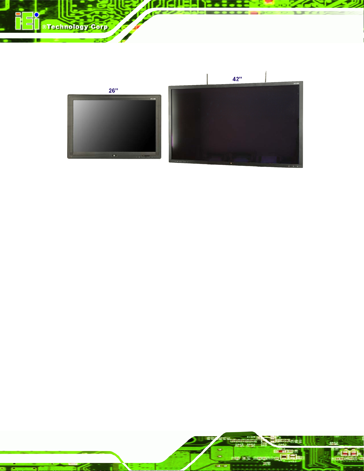
Figure 1-1: AFL-26/42A-9652
AFL-26/42A-9652 Panel PC
The AFL-26/42A-9652 is a large screen panel PC. There are 26” and 42” models. Both are
available with a super-tough front panel, capable of withstanding scratching and
incorporating a glare-reducing coating for areas of high brightness or direct light. The 26”
also offers a touch screen model that gives the most direct interactivity possible, and still
retains the glare-reducing layer.
The AFL-26/42A-9652 is a self-contained system, with all parts, including the power
supply, contained inside the casing allowing a completely interactive panel PC with only a
single power cable. External devices are connected wirelessly through Bluetooth
technology and network access is enabled through a “draft n” wireless adapter. Wired
options are always available on the rear panel, with two serial ports and four USB ports for
peripherals and two Gigabit Ethernet slots for networking.
1.2 Model Variations
The AFL-26/42A-9652 model variations are shown below:
Processor and memory options
Page 2
o 2.0 GHz Intel® Celeron® M 550 with 1 GB RAM
o 2.2 GHz Intel® Core™2 Duo T7500 with 2.0 GB RAM
Screen options
o 42” with tempered glass
Page 17

AFL-26/42A-9652 Panel PC
o 26” with tempered glass
o 26” with touch screen
1.3 Benefits
The AFL-26/42A-9652 is designed to enhance the customers experience and gain new
customers.
Banking
o Reduce perceived waiting times
o Increase cross-selling of related banking products
o Increase revenue through local advertising
Casinos
o Promote entertainment events
o Live news, weather and flight schedules
o Guest room TV network
Hotels
o Digitized maps
o Advertise amenities like spas, restaurants, sporting facilities and
conference rooms
Airports and bus terminals
o Up to the minute schedule information
o Advertising
Stores
o Product highlights or current sales
o Storefront advertising
1.4 Standard Features
Some of the standard features of the AFL-26/42A-9652 flat panel PC include:
Fully self-contained, only a power cable required
Anti-glare screen coating
Touch screen or scratch proof tempered glass
1 GB or more of memory
AT/ATX power mode supported
Wireless LAN
Page 3
Page 18
Gigabit Ethernet
CompactFlash® slot
Bluetooth
Externally accessible hard drive tray (42” only)
RoHS compliant
1.5 External Overview
The AFL-26/42A-9652 consists of a screen and rear panel that covers the back, sides and
top. The rear panel contains a smaller access panel, all the cable connections and the
mounting holes.
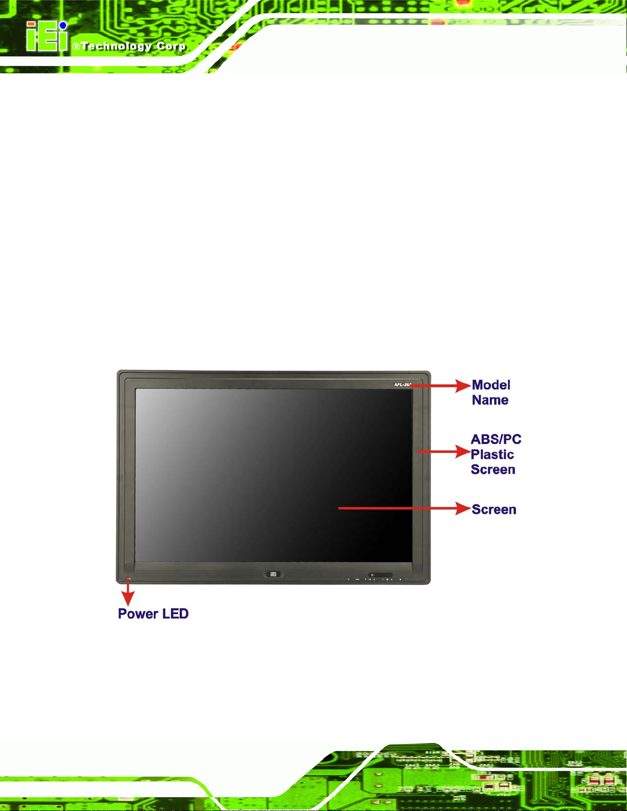
1.5.1 Front Panel
The front side of the AFL-26/42A-9652 is a flat panel TFT LCD screen surrounded by a
plastic frame.
AFL-26/42A-9652 Panel PC
Page 4
Figure 1-2: AFL-26A Front Panel
Page 19

AFL-26/42A-9652 Panel PC
Figure 1-3: AFL-642A Front Panel
1.5.2 Rear Panel
The rear panel provides access to retention screw holes that support the wall mounting.
Refer to
Figure 1-4: AFL-26A Rear Panel
Figure 1-4.
Page 5
Page 20
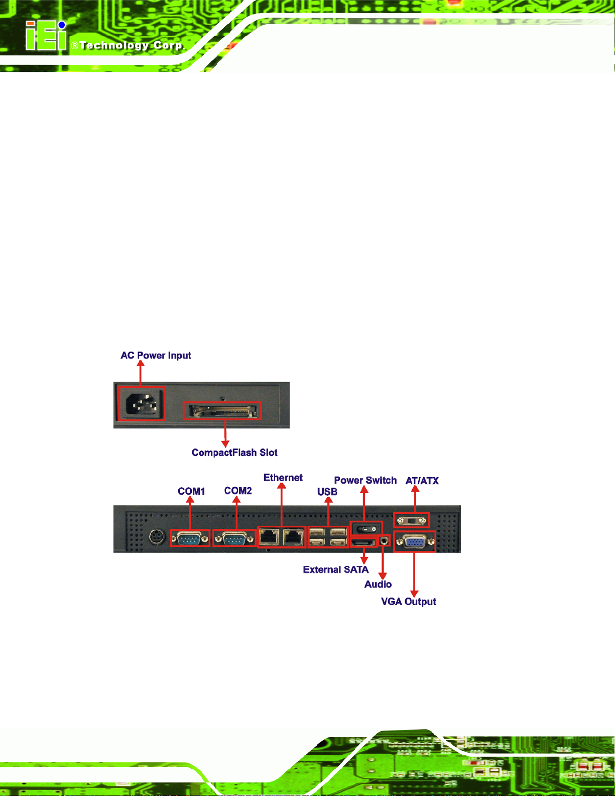
1.5.3 Bottom Panel
The bottom panel of the AFL-26/42A-9652 has the following slots and buttons (Figure 1-5):
1 x AC input
1 x AT/ATX selection switch
1 x Audio output connector
1 x CompactFlash® slot
2 x Gigabit Ethernet connector
1 x Hard drive bay (42” only)
1 x Power switch
1 x RS-232 serial port connector
1 x RS-232/422/485 serial port connector
4 x USB connector
1 x VGA video output
AFL-26/42A-9652 Panel PC
Page 6
Figure 1-5: AFL-26A Bottom Panel
Page 21
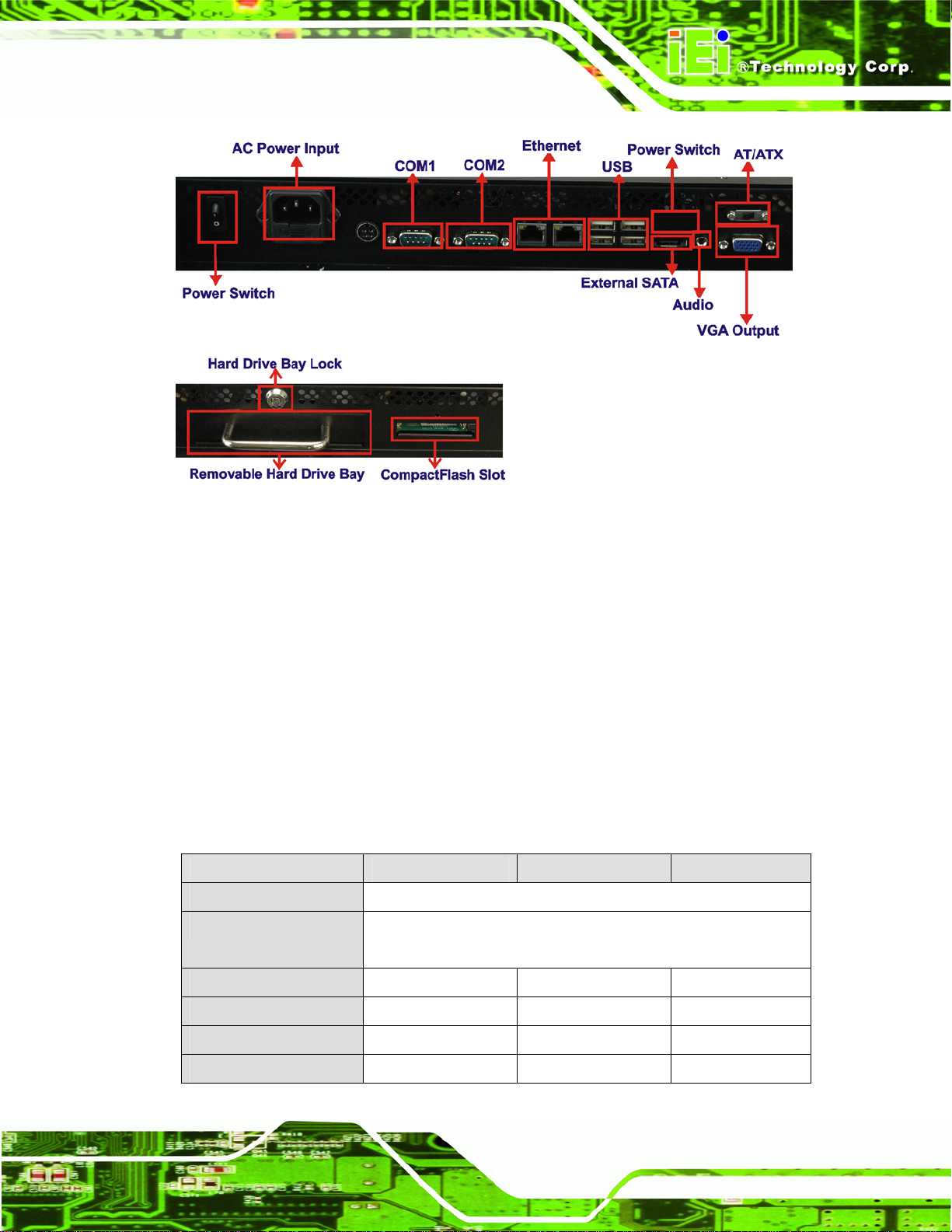
AFL-26/42A-9652 Panel PC
Figure 1-6: AFL-642A Bottom Panel
1.6 Internal Overview
All the components are contained under the rear panel. The internal components include
the power supply for converting AC to DC current, the touch panel module and the
motherboard. The motherboard has memory, wireless module, a hard drive and
CompactFlash® bracket installed. The 42” model also includes the removable hard drive
bracket. The internals also include the LCD panel and touch screen panel.
1.7 Specifications
The technical specifications for the AFL-26/42A-9652 systems are listed in Table 1-1.
SPECIFICATION 26” with touch 26” 42”
Mainboard AFLMB-9652-R10
CPU 2.2GHz Intel® Core™2 Duo T7500 or
LCD Panel 25.4" 25.4" 42"
Resolution 1920 x 1200 1920 x 1200 1366 x 768
2.0GHz Intel® Celeron® M 550
Brightness 350 350 500
Contrast Ratio 1500:1 1500:1 800:1
Page 7
Page 22

SPECIFICATION 26” with touch 26” 42”
LCD Colors 16.7 million
Pixel Pitch 0.2865 x 0.2865 0.2865 x 0.2865 0.681 x 0.681
Viewing Angle (H/V) 176/176 176/176 178 / 178
Backlight MTBF 50000 50000 60000
Touch Screen 5-wire SAW type
Housing Material ABS + PC Plastic front frame
IP Level IP 64 front panel
Drive Bay 2.5” SATA
SSD CompactFlash® Type I/II
Audio 2 x 6 W 2 x 6 W 2 x 10 W
I/O 1 x AC input
1 x AT/ATX selection switch
1 x Audio output connector
AFL-26/42A-9652 Panel PC
1 x CompactFlash® slot
2 x Gigabit Ethernet connector
1 x Hard drive slot (42” only)
1 x Power switch
1 x RS-232 serial port connector
1 x RS-232/422/485 serial port connector
4 x USB connector
1 x VGA video output
Power Adapter 100-240 VAC input, 12 V output
Power Consumption 153 W 259 W
Mounting Feature VESA 200 x 100 VESA 400 x 200
Operating Temp. 0ºC ~ 40ºC
Dimension (WxHxD) 623 x 425 x 100 623 x 425 x 100 990 x 582 x 135
Net/Gross Weight 12 kg 35 kg
Front Panel Protection IP 64 compliant
EMC and Safety CE, FCC, CCC , UL, CB
Page 8
Table 1-1: AFL-26/42A-9652 System Specifications
Page 23

AFL-26/42A-9652 Panel PC
1.8 Dimensions
1.8.1 26” Dimensions
The dimensions of the 26” models are shown in Figure 1-7 below.
Figure 1-7: 26” Dimensions (units in mm)
Page 9
Page 24

1.8.2 42” Dimensions
The dimensions of the 42” flat panel PC are shown in Figure 1-8 below.
AFL-26/42A-9652 Panel PC
Page 10
Figure 1-8: 42” Dimensions (units in mm)
Page 25

AFL-26/42A-9652 Panel PC
Chapter
2
2 Installation
Page 11
Page 26

AFL-26/42A-9652 Panel PC
WARNING:
When installing the AFL-26/42A-9652, make sure to:
Turn the power off: Chance of electrocution. Turn off the monitor
and unplug it from the power supply.
Only let certified engineers change the hardware settings:
Incorrect settings can cause irreparable damage to the product.
Install the monitor with assistan ce: The product is very heavy and
may be damaged by drops and bumps. Two or more people should
install the panel PC.
Take anti-static precautions: Electrostatic discharge can destroy
electrical components and injure the user. Users must ground
themselves using an anti-static wristband or similar device.
The installation steps below should be followed in order.
Step 1: Unpack the flat panel PC
Step 2: Check all the required parts are included
Step 3: Install the CompactFlash® card
Step 4: Install the hard drive (42” model)
Step 5: Set the AT/ATX mode
Step 6: Mount the flat panel PC
Step 7: Connect peripheral devices to the bottom panel of the flat panel PC
Step 8: Connect the power cable
Step 9: Configure the system Step 0:
2.1 Unpack the Panel PC
Page 12
To unpack the flat panel PC, follow the steps below:
Page 27
AFL-26/42A-9652 Panel PC
WARNING!
Only remove the protective plastic cover stuck to the front screen after
installation. The plastic layer protects the monitor surface during
installation process.
Step 1: Carefully cut the tape sealing the box. Only cut deep enough to break the tape.
Step 2: Open the outside box.
Step 3: Carefully cut the tape sealing the box. Only cut deep enough to break the tape.
Step 4: Open the inside box.
Step 5: Lift the monitor out of the boxes.
Step 6: Remove the peripheral parts box from the main box. Step 0:
2.2 Packing List
The AFL-26/42A-9652 flat panel PC is shipped with the following components:
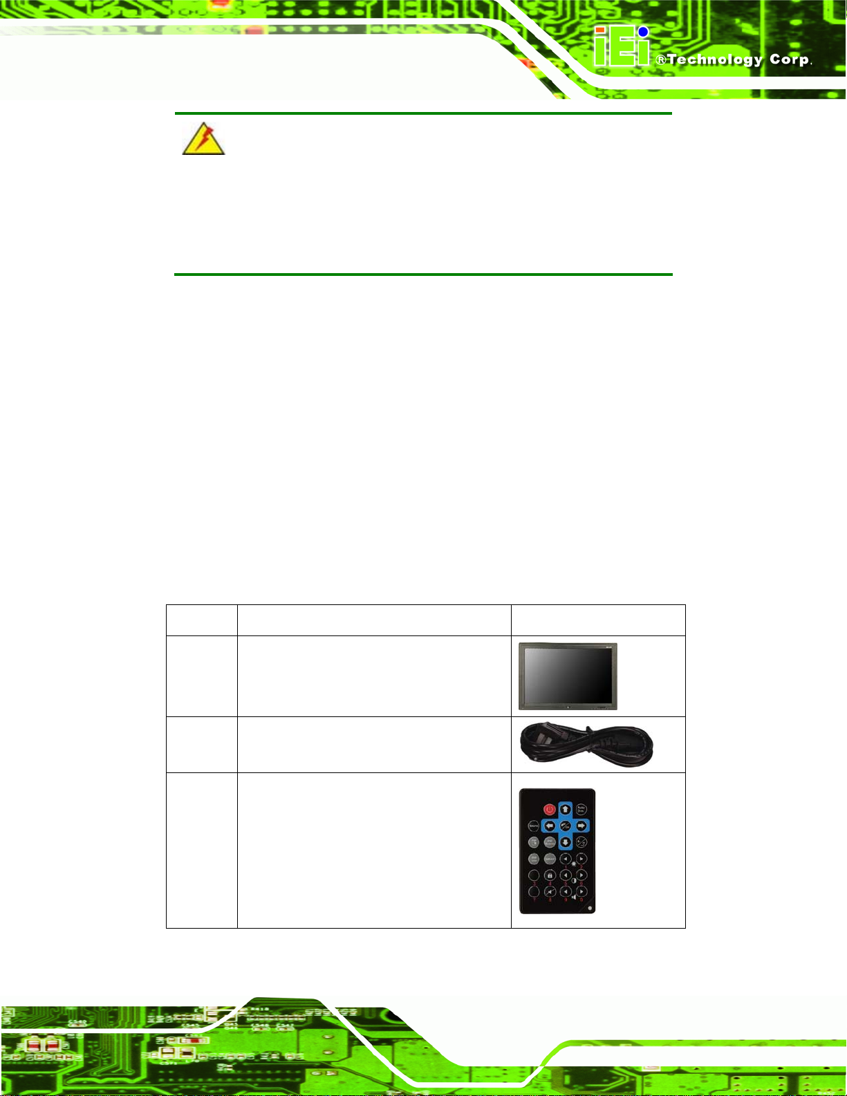
Quantity Item Image
1 AFL-26/42A-9652
1 Power cord
1 Remote control (batteries included)
Page 13
Page 28

Quantity Item Image
1 User manual CD
1 Antenna set (42” only)
Table 2-1: Packing List
If any of these items are missing or damaged, contact the distributor or sales
representative immediately.
2.3 Optional Items
Quantity Item Image
AFL-26/42A-9652 Panel PC
1 1 GB CompactFlash® card with Windows
XPE pre-installed
Table 2-2: Optional Items
2.4 CompactFlash® Card Installation
The AFL-26/42A-9652 has one CompactFlash® slot inside the rear panel.
To install the CompactFlash® card, slide it into the CompactFlash® card slot on the
external connector panel.
Page 14
Page 29
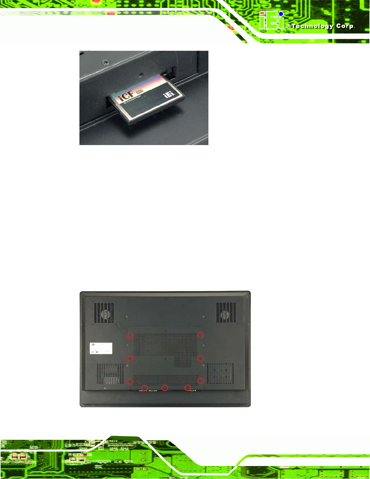
AFL-26/42A-9652 Panel PC
Figure 2-1: Back Cover Retention Screws
2.5 Hard Drive Installation
The section outlines the internal hard drive installation for the AFL-26A and the external
hard drive installation for the AFL-642A.
2.5.1 AFL-26A Internal Hard Drive Installation
To install the hard drive, please follow the steps below:
Step 1: Remove the plastic back cover. See Section
Step 2: Remove the retention screws securing the internal aluminum cover (
2.4 above.
Figure 2-2).
Figure 2-2: Aluminum Back Cover Retention Screws
Page 15
Page 30

Step 3: Lift the aluminum cover to remove.
AFL-26/42A-9652 Panel PC
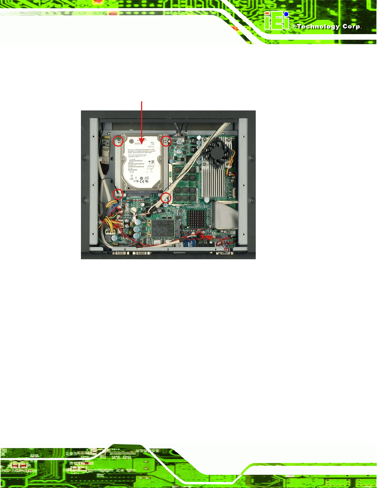
Step 4: Remove the four HDD bracket retention screws (
bracket off the panel PC.
Figure 2-3) and lift the HDD
Figure 2-3: HDD Bracket Retention Screws
Step 5: Attach the HDD brackets to the HDD. To do this, align the four retention screw
holes on the bottom of the HDD bracket with the retention screw holes on the
sides of the HDD. Insert four retention screws into the HDD bracket (
Figure 2-4: HDD Retention Screws
Figure 2-4).
Page 16
Page 31
AFL-26/42A-9652 Panel PC
Step 6: Install the hard drive in the same position it was before.
Step 7: Slide down from the top to connect the motherboard SATA connector to the hard
drive SATA connector.
Figure 2–5: HDD Installation
Step 8: Fasten the screws, with the grounding wire connected to one of them. Step 0:
2.5.2 AFL-642A Hard Drive Installation
To install a hard drive in the removable hard drive tray, follow the steps below.
Step 1: Unlock the tray and remove it by pulling it out.
Page 17
Page 32
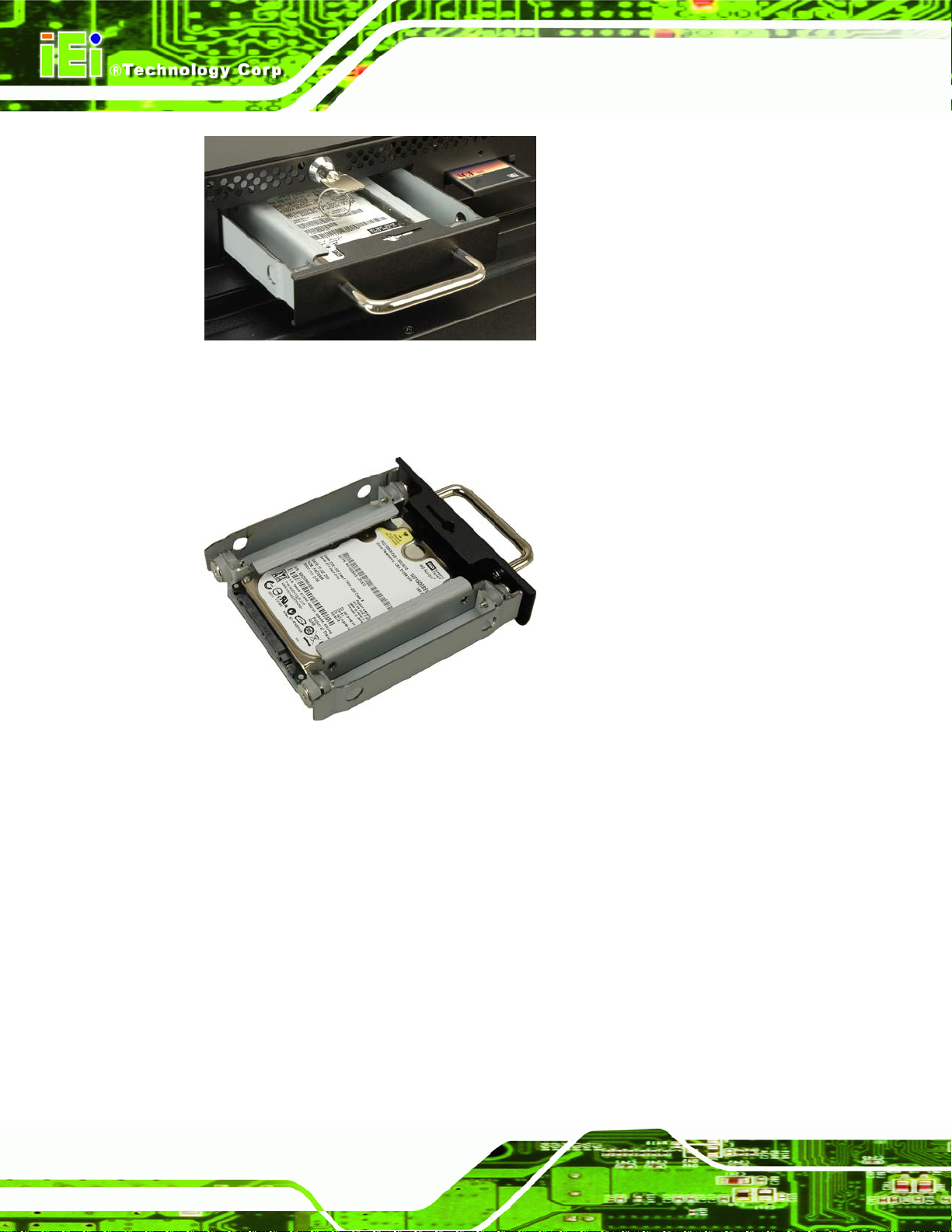
Figure 2–6: HDD Tray Removal
Step 2: Install the hard drive in the tray and fasten the hard drive screws.
AFL-26/42A-9652 Panel PC
Figure 2–7: HDD Tray Removal
Step 3: Push the hard drive bay back into place and lock. Step 0:
2.6 AT/ATX Mode Selection
Choose AT or ATX power mode by toggling the switch on the rear I/O panel. The section
below briefly explain the differences between AT and ATX power modes.
Page 18
Page 33

AFL-26/42A-9652 Panel PC
Figure 2-8: AT/ATX Switch Location
2.6.1 ATX Power Mode
ATX power mode enables advanced power features. The advanced power features include
turning the panel PC on and off through a network connection. The feature allows the panel
PC to be remotely started or stopped when necessary without access to the power supply
of the panel PC. The panel PC can be set to turn on automatically when power is turned off,
or stay off.
Security surveillance
Point-of-Sale (POS)
Advertising terminal
2.6.2 AT Power Mode
AT mode does not support the network power features of the ATX power mode. When in
AT power mode the power is controlled by the central power switch. The panel PC turns on
when the main power is turned on.
ATM
Self-service kiosk
Plant environment monitoring system
Factory automation platform
Manufacturing shop flow
Page 19
Page 34
2.7 Mounting the System
WARNING!
The panel PC is very heavy. Two or more people should mount the
panel PC. Dropping or bumping the panel PC during installation can
cause serious or irreparable damage to the panel PC.
The following installation options are available:
Lift stand
Wall arm
Wall mount
Ceiling mount
AFL-26/42A-9652 Panel PC
Mobile mount
The installation instructions are included with the stand, arm or mount.
2.8 Bottom Panel Connectors
The bottom panel connectors extend the capabilities of the panel PC but are not essential
for operation (except power).
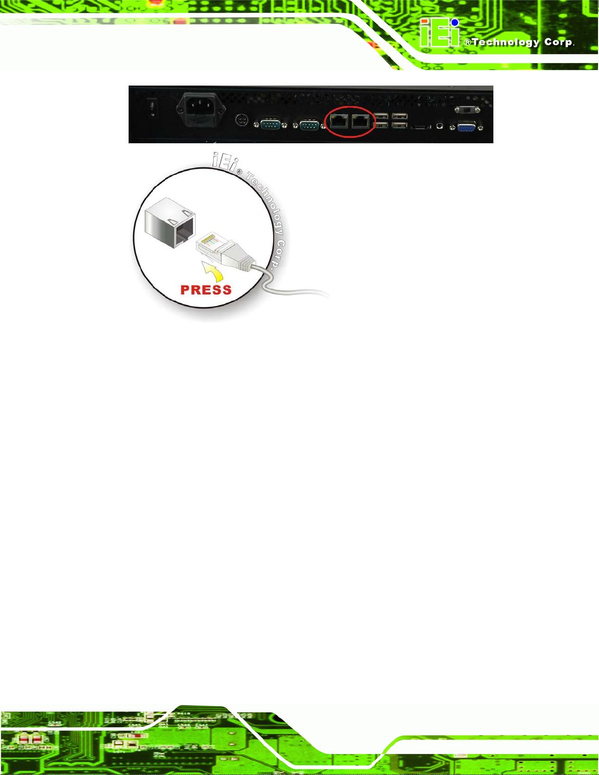
2.8.1 LAN Connection
The RJ-45 connectors enable connection to an external network. To connect a LAN cable
with an RJ-45 connector, please follow the instructions below.
Step 1: Locate the RJ-45 connector on the bottom panel of the AFL-26/42A-9652.
Step 2: Align the connectors. Align the RJ-45 connector on the LAN cable with one of
the RJ-45 connectors on the bottom panel of the AFL-26/42A-9652. See
Figure 2-9..
Page 20
Page 35
AFL-26/42A-9652 Panel PC
Figure 2-9: LAN Connection
Step 3: Insert the LAN cable RJ-45 connector. Once aligned, gently insert the LAN
cable RJ-45 connector into the onboard RJ-45 port. Step 3:
2.8.2 Serial Device Connection
The serial device connectors are for connecting serial devices to the AFL-26/42A-9652.
Follow the steps below to connect a serial device to the AFL-26/42A-9652 panel PC.
Step 4: Locate the DB-9 connector. The location of the DB-9 connector is shown in
Chapter 2.
Step 5: Insert the serial connector. Insert the DB-9 connector of a serial device into the
DB-9 connector on the bottom panel. See
Figure 2-10.
Page 21
Page 36

Figure 2-10: Serial Device Connector
AFL-26/42A-9652 Panel PC
Step 6: Secure the connector. Secure the serial device connector to the external
interface by tightening the two retention screws on either side of the connector.
2.8.3 USB Device Connection
To connect USB devices to the AFL-26/42A-9652, please follow the instructions below.
Step 7: Located the USB connectors. The locations of the USB connectors are shown
in Chapter 2.
Step 8: Align the connectors. Align the USB device connector with one of the
connectors on the bottom panel. See
Figure 2-11.
Step 6:
Page 22
Page 37

AFL-26/42A-9652 Panel PC
Figure 2-11: USB Device Connection
Step 9: Insert the device connector. Once aligned, gently insert the USB device
connector into the onboard connector. Step 9:
2.8.4 VGA Monitor Connection
The VGA output can be connected to an external VGA monitor. To connect the VGA
monitor to the AFL-26/42A-9652, please follow the instructions below.
Step 10: Locate the female DB-15 connector. The location of the female DB-15
connector is shown in Chapter 3.
Step 11: Align the VGA connector. Align the male DB-15 connector on the VGA screen
cable with the female DB-15 connector on the external peripheral interface.
Step 12: Insert the VGA connector. Once the connectors are properly aligned with the
insert the male connector from the VGA screen into the female connector on the
AFL-26/42A-9652. See
Figure 2-12.
Page 23
Page 38

AFL-26/42A-9652 Panel PC
Figure 2-12: VGA Connector
Step 13: Secure the connector. Secure the DB-15 VGA connector from the VGA monitor
to the external interface by tightening the two retention screws on either side of
the connector. Step 13:
2.9 Power Connection
The power cable connects the panel PC to the power supply. The power cable is required
for operation of the panel PC.
Figure 2-13: VGA Connector
Page 24
Step 14: Connect one end to the panel PC.
Step 15: Connect the other end to a 100-240 VAC single-phase power supply Step 15:
Page 39
AFL-26/42A-9652 Panel PC
2.10 Jumper Settings
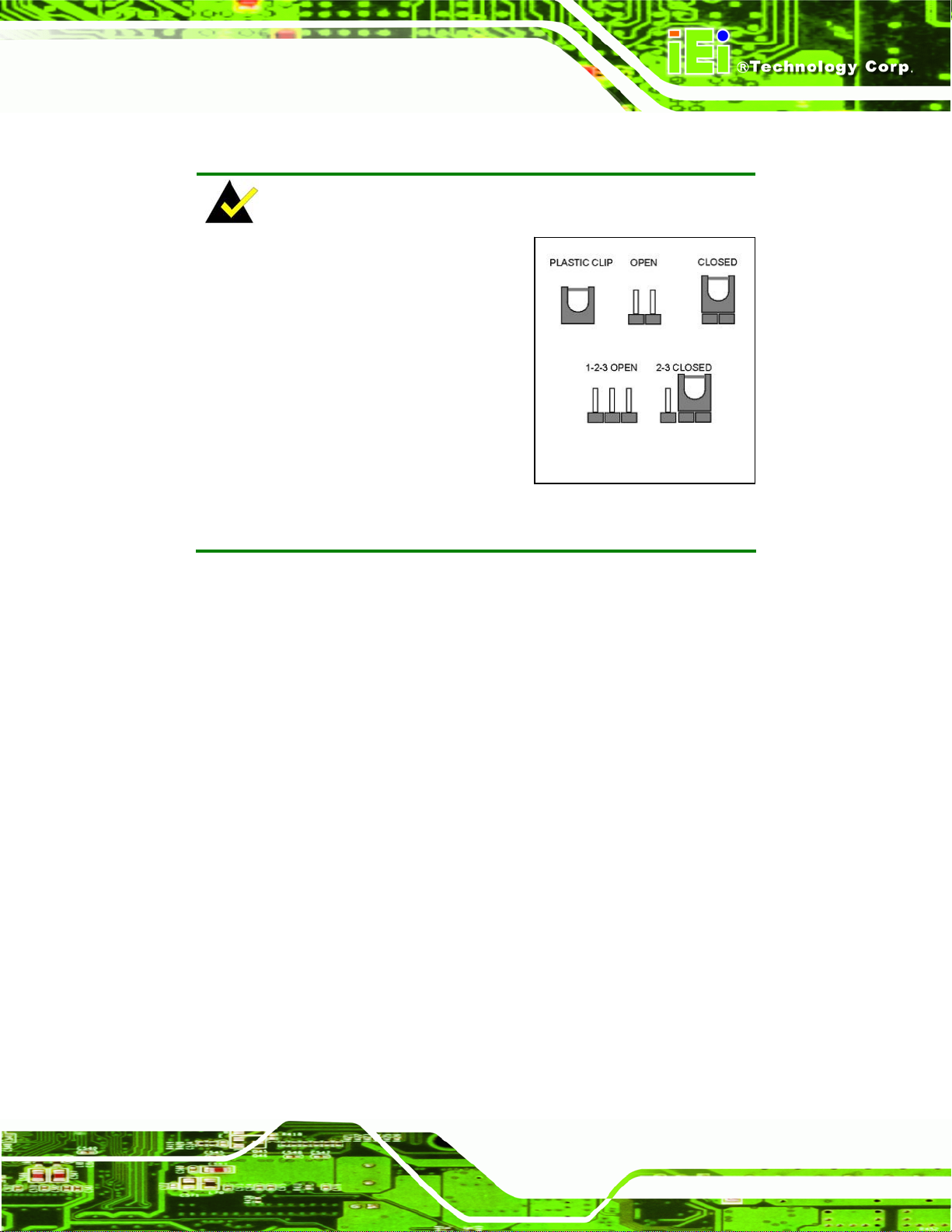
NOTE:
A jumper is a metal bridge that is used
to close an electrical circuit. It consists
of two metal pins and a small metal
clip (often protected by a plastic
cover) that slides over the pins to
connect them. To CLOSE/SHORT a
jumper means connecting the pins of
the jumper with the plastic clip and to
OPEN a jumper means removing the
plastic clip from a jumper.
The motherboard jumpers are listed below.
CompactFlash® setup
COM1 pin 9 setup
COM2 pin 9 setup
COM3 pin 9 setup
COM3 RS-232/422/485 selection
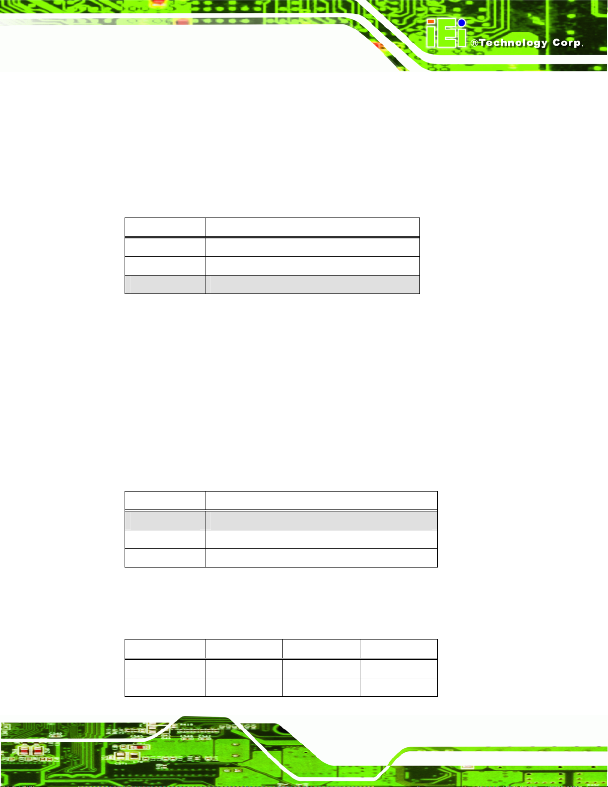
2.10.1 CompactFlash® Card Setup
Jumper Label: J4
Jumper Type:
Jumper Settings:
2-pin header
Table 2-3
See
Jumper
The CompactFlash® card setup jumper sets the CompactFlash® card as the IDE master or
IDE slave.
Page 25
Page 40

J4 Description
Open Slave
Closed Master
Table 2-3: CF Card Setup Jumper Settings
2.10.2 COM1 Pin-9 Setup
Jumper Label: J10
AFL-26/42A-9652 Panel PC
Jumper Type:
Jumper Settings:
10-pin header
Table 2-4
See
The COM1 pin-9 signal can be selected as 12 V, 5 V or Ring.
J10 Description
1-3 12 V
3-5 5 V
7-9 RI
Table 2-4: COM1 Pin-9 Setup
2.10.3 COM2 Pin-9 Setup
Jumper Label: J6
Jumper Type:
Jumper Settings:
6-pin header
Table 2-5
See
Page 26
The COM2 pin-9 signal can be selected as 12 V, 5 V or Ring.
JP3 Description
1-2 12 V
3-4 RI
5-6 5 V
Table 2-5: COM2 Pin-9 Setup
Page 41
AFL-26/42A-9652 Panel PC
2.10.4 COM3 Pin-9 Setup
Jumper Label: J10
Jumper Type:
Jumper Settings:
10-pin header
Table 2-6
See
The COM3 pin-9 signal can be selected as 12 V, 5 V or Ring.
J10 Description
2-4 12 V
4-6 5 V
8-10 RI
Table 2-6: COM3 Pin-9 Setup
2.10.5 COM3 RS-232/422/485 Setup
Jumper Label: J7
Jumper Type:
Jumper Settings:
6-pin header
Table 2-7
See
The COM3 serial port can be set to use RS-232, RS-422 or RS-485 communication
methods.
J7 Description
1-2 RS-232
3-4 RS-422
5-6 RS-485
Table 2-7: COM3 RS-232/422/485 Setup
The pinouts for RS-232, RS-422 and RS-485 communication are shown below.
COM3 RS-232 RS-422 RS-485
1 DCD TX- D2 RX TX+ D+
Page 27
Page 42

COM3 RS-232 RS-422 RS-485
3 TX
4 DTR
5 GND
6 DSR RX-
7 RTS RX+
8 CTS
9 RI
AFL-26/42A-9652 Panel PC
Table 2-8: COM3 Pinouts
Page 28
Page 43

AFL-26/42A-9652 Panel PC
Chapter
3
3 BIOS Setup
Page 29
Page 44

3.1 Introduction
A licensed copy of AMI BIOS is preprogrammed into the ROM BIOS. The BIOS setup
program allows users to modify the basic system configuration. This chapter describes
how to access the BIOS setup program and the configuration options that may be changed.
3.1.1 Starting Setup
The AMI BIOS is activated when the computer is turned on. The setup program can be
activated in one of two ways.
AFL-26/42A-9652 Panel PC
1. Press the D
2. Press the D
message appears on the screen.
If the message disappears before the D
again.
ELETE key as soon as the system is turned on or
ELETE key when the “Press Del to enter SETUP”
ELETE key is pressed, restart the computer and try
3.1.2 Using Setup
Use the arrow keys to highlight items, press ENTER to select, use the PageUp and
PageDown keys to change entries, press F1 for help and press E
keys are shown in.
Key Function
Up arrow Move to previous item
Down arrow Move to next item
Left arrow Move to the item on the left hand side
SC to quit. Navigation
Page 30
Right arrow Move to the item on the right hand side
Esc key Main Menu – Quit and not save changes into CMOS
Status Page Setup Menu and Option Page Setup Menu --
Exit current page and return to Main Menu
Page Up key Increase the numeric value or make changes
Page Dn key Decrease the numeric value or make changes
Page 45

AFL-26/42A-9652 Panel PC
Key Function
F1 key General help, only for Status Page Setup Menu and Option
Page Setup Menu
F2 /F3 key Change color from total 16 colors. F2 to select color
forward.
F10 key Save all the CMOS changes, only for Main Menu
Table 3-1: BIOS Navigation Keys
3.1.3 Getting Help
When F1 is pressed a small help window describing the appropriate keys to use and the
possible selections for the highlighted item appears. To exit the Help Window press E
the F1 key again.
3.1.4 Unable to Reboot After Configuration Changes
If the computer cannot boot after changes to the system configuration is made, CMOS
defaults. Use the jumper described in Chapter 5.
3.1.5 BIOS Menu Bar
The menu bar on top of the BIOS screen has the following main items:
Main Changes the basic system configuration.
Advanced Changes the advanced system settings.
PCIPnP Changes the advanced PCI/PnP Settings
Boot Changes the system boot configuration.
Security Sets User and Supervisor Passwords.
Chipset Changes the chipset settings.
SC or
Power Changes power management settings.
Exit Selects exit options and loads default settings
The following sections completely describe the configuration options found in the menu
items at the top of the BIOS screen and listed above.
Page 31
Page 46

3.2 Main
The Main BIOS menu (5BIOS Menu 1) appears when the BIOS Setup program is entered.
The Main menu gives an overview of the basic system information.
AFL-26/42A-9652 Panel PC
BIOS Menu 1: Main
Î System Overview
The System Overview lists a brief summary of different system components. The fields in
System Overview cannot be changed. The items shown in the system overview include:
AMI BIOS: Displays auto-detected BIOS information
Processor: Displays auto-detected CPU specifications
Page 32
o Version: Current BIOS version
o Build Date: Date the current BIOS version was made
o ID: Installed BIOS ID
o Type: Names the currently installed processor
o Speed: Lists the processor speed
o Count: The number of CPUs on the motherboard
Page 47

AFL-26/42A-9652 Panel PC
System Memory: Displays the auto-detected system memory.
o Size: Lists memory size
The System Overview field also has two user configurable fields:
Î System Time [xx:xx:xx]
Use the System Time option to set the system time. Manually enter the hours, minutes and
seconds.
Î System Date [xx/xx/xx]
Use the System Date option to set the system date. Manually enter the day, month and
year.
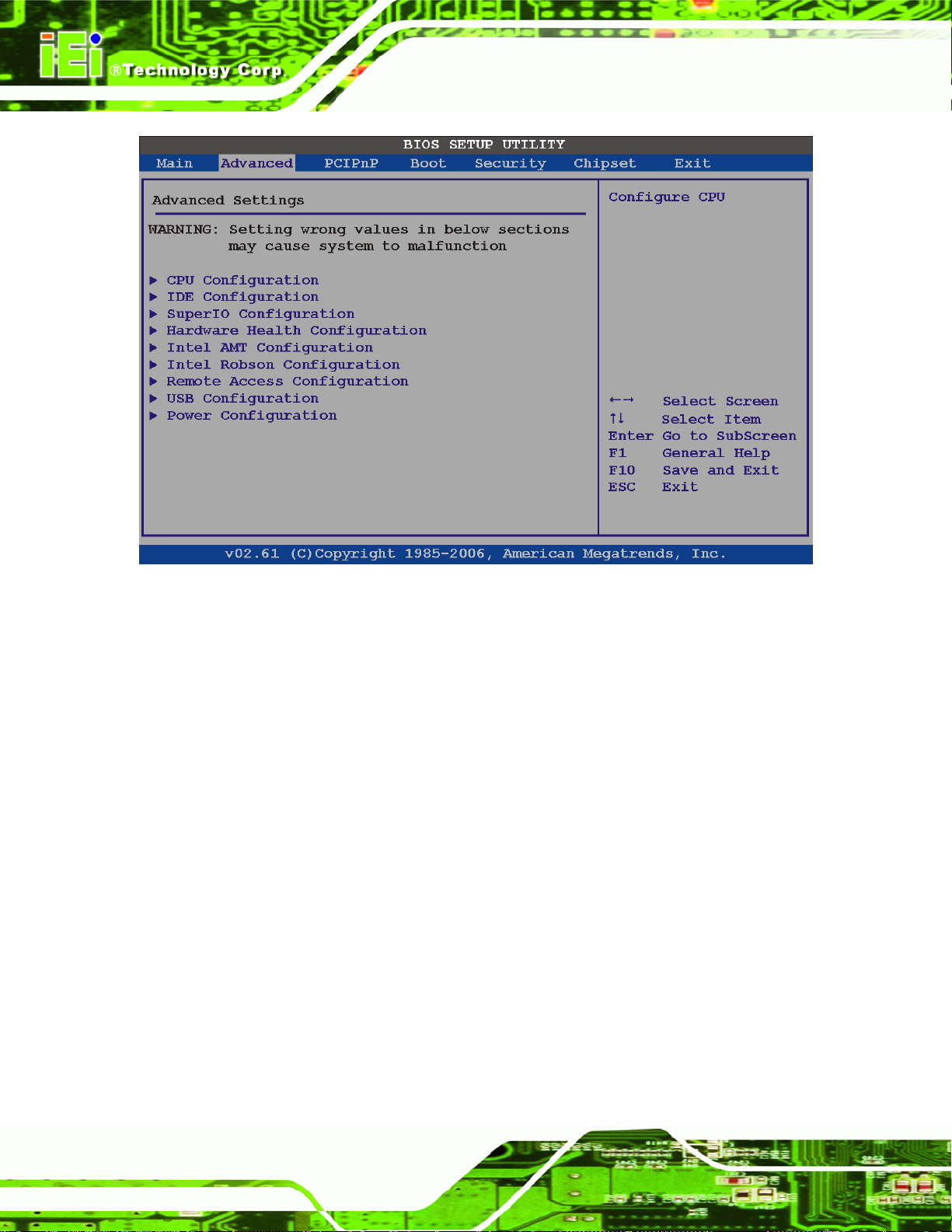
3.3 Advanced
Use the Advanced menu (5BIOS Menu 2) to configure the CPU and peripheral devices
through the following sub-menus:
WARNING:
Setting the wrong values in the sections below may cause the system to
malfunction. Make sure that the settings made are compatible with the
hardware.
3.3.1 CPU Configuration............................................................................................ 35
3.3.2 IDE Configuration ............................................................................................. 36
3.3.3 Super IO Configuration .....................................................................................43
3.3.4 Hardware Health Configuration ........................................................................ 45
3.3.5 Intel AMT Configuration ....................................................................................50
3.3.6 Intel Robson Configuration ............................................................................... 53
3.3.7 Remote Configuration....................................................................................... 54
3.3.8 USB Configuration............................................................................................ 58
3.3.9 Power Configuration ......................................................................................... 60
Page 33
Page 48
AFL-26/42A-9652 Panel PC
BIOS Menu 2: Advanced
Page 34
Page 49

AFL-26/42A-9652 Panel PC
3.3.1 CPU Configuration
Use the CPU Configuration menu (5BIOS Menu 3) to view detailed CPU specifications
and configure the CPU.
BIOS Menu 3: CPU Configuration
The CPU Configuration menu (
Manufacturer: Lists the name of the CPU manufacturer
Brand String: Lists the brand name of the CPU being used
Frequency: Lists the CPU processing speed
FSB Speed: Lists the FSB speed
Cache L1: Lists the CPU L1 cache size
Cache L2: Lists the CPU L2 cache size
Ratio Value: Lists the clock multiplier
5BIOS Menu 3) lists the following CPU details:
Page 35
Page 50
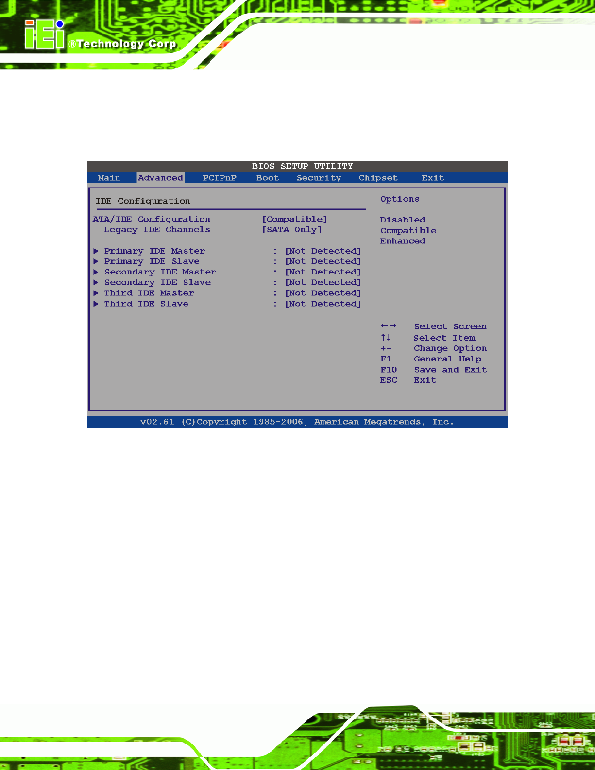
3.3.2 IDE Configuration
Use the IDE Configuration menu (5BIOS Menu 4) to change and/or set the configuration of
the IDE devices installed in the system.
AFL-26/42A-9652 Panel PC
BIOS Menu 4: IDE Configuration
Î ATA/IDE Configurations [Compatible]
Use the ATA/IDE Configurations option to configure the ATA/IDE controller.
Î
Disabled
Î
Compatible
Page 36
Disables the on-board ATA/IDE controller.
Configures the on-board ATA/IDE controller to be in
compatible mode. In this mode, a SATA channel will
replace one of the IDE channels. This mode supports
up to 4 storage devices.
Page 51

AFL-26/42A-9652 Panel PC
Î
Enhanced DEFAULT
Configures the on-board ATA/IDE controller to be in
Enhanced mode. In this mode, IDE channels and
SATA channels are separated. This mode supports
up to 6 storage devices. Some legacy OS do not
support this mode.
Î Legacy IDE Channels [SATA Only]
Î
SA TA Only DEFAULT
Î
SA TA Pri, PATA Sec
Î
PATA Only
Î IDE Master and IDE Slave
Only the SATA drives are enabled.
The IDE drives are enabled on the Primary
IDE channel. The SATA drives are enabled on
the Secondary IDE channel.
The IDE drives are enabled on the primary
and secondary IDE channels. SATA drives are
disabled.
When entering setup, BIOS auto detects the presence of IDE devices. BIOS displays the
status of the auto detected IDE devices. The following IDE devices are detected and are
shown in the IDE Configuration menu:
Primary IDE Master
Primary IDE Slave
Secondary IDE Master
Secondary IDE Slave
The IDE Configuration menu (
5BIOS Menu 4) allows changes to the configurations for the
IDE devices installed in the system. If an IDE device is detected, and one of the above
listed four BIOS configuration options are selected, the IDE configuration options shown in
Section 87
53.3.2.1 appear.
Page 37
Page 52

3.3.2.1 IDE Master, IDE Slave
Use the IDE Master and IDE Slave configuration menu to view both primary and
secondary IDE device details and configure the IDE devices connected to the system.
AFL-26/42A-9652 Panel PC
BIOS Menu 5: IDE Master and IDE Slave Configuration
Î Auto-Detected Drive Parameters
The “grayed-out” items in the left frame are IDE disk drive parameters automatically
detected from the firmware of the selected IDE disk drive. The drive parameters are listed
as follows:
Device: Lists the device type (e.g. hard disk, CD-ROM etc.)
Type: Indicates the type of devices a user can manually select
Vendor: Lists the device manufacturer
Size: List the storage capacity of the device.
LBA Mode: Indicates whether the LBA (Logical Block Addressing) is a method
of addressing data on a disk drive is supported or not.
Page 38
Page 53

AFL-26/42A-9652 Panel PC
Block Mode: Block mode boosts IDE drive performance by increasing the
amount of data transferred. Only 512 bytes of data can be transferred per
interrupt if block mode is not used. Block mode allows transfers of up to 64 KB
per interrupt.
PIO Mode: Indicates the PIO mode of the installed device.
Async DMA: Indicates the highest Asynchronous DMA Mode that is
supported.
Ultra DMA: Indicates the highest Synchronous DMA Mode that is supported.
S.M.A.R.T.: Indicates whether or not the Self-Monitoring Analysis and
Reporting Technology protocol is supported.
32Bit Data Transfer: Enables 32-bit data transfer.
Î Type [Auto]
Use the Type BIOS option select the type of device the AMIBIOS attempts to boot from
after the Power-On Self-Test (POST) is complete.
Î
Not Installed
Î
Auto DEFAULT
Î
CD/DVD
Î
ARMD
BIOS is prevented from searching for an IDE disk drive
on the specified channel.
The BIOS auto detects the IDE disk drive type
attached to the specified channel. This setting should
be used if an IDE hard disk drive is attached to the
specified channel.
The CD/DVD option specifies that an IDE CD-ROM
drive is attached to the specified IDE channel. The
BIOS does not attempt to search for other types of IDE
disk drives on the specified channel.
This option specifies an ATAPI Removable Media
Device. These include, but are not limited to:
ZIP
LS-120
Page 39
Page 54

Î LBA/Large Mode [Auto]
Use the LBA/Large Mode option to disable or enable BIOS to auto detects LBA (Logical
Block Addressing). LBA is a method of addressing data on a disk drive. In LBA mode, the
maximum drive capacity is 137 GB.
AFL-26/42A-9652 Panel PC
Î
Disabled
Î
Auto DEFAULT
Î Block (Multi Sector Transfer) [Auto]
Use the Block (Multi Sector Transfer) to disable or enable BIOS to auto detect if the
device supports multi-sector transfers.
Î
Disabled
Î
Auto DEFAULT
BIOS is prevented from using the LBA mode control on the
specified channel.
BIOS auto detects the LBA mode control on the specified
channel.
BIOS is prevented from using Multi-Sector Transfer on the
specified channel. The data to and from the device occurs
one sector at a time.
BIOS auto detects Multi-Sector Transfer support on the
drive on the specified channel. If supported the data
transfer to and from the device occurs multiple sectors at a
time.
Î PIO Mode [Auto]
Use the PIO Mode option to select the IDE PIO (Programmable I/O) mode program timing
cycles between the IDE drive and the programmable IDE controller. As the PIO mode
increases, the cycle time decreases.
Î
Auto DEFAULT
Î
0
Î
1
Î
2
Page 40
BIOS auto detects the PIO mode. Use this value if the IDE disk
drive support cannot be determined.
PIO mode 0 selected with a maximum transfer rate of 3.3 MB/s
PIO mode 1 selected with a maximum transfer rate of 5.2 MB/s
PIO mode 2 selected with a maximum transfer rate of 8.3 MB/s
Page 55

AFL-26/42A-9652 Panel PC
Î
3
Î
4
Î DMA Mode [Auto]
Use the DMA Mode BIOS selection to adjust the DMA mode options.
Î
Auto DEFAULT
Î
SWDMA0
Î
SWDMA1
PIO mode 3 selected with a maximum transfer rate of 11.1 MB/s
PIO mode 4 selected with a maximum transfer rate of 16.6 MB/s
(This setting generally works with all hard disk drives
manufactured after 1999. For other disk drives, such as IDE
CD-ROM drives, check the specifications of the drive.)
BIOS auto detects the DMA mode. Use this value if the IDE
disk drive support cannot be determined.
Single Word DMA mode 0 selected with a maximum data
transfer rate of 2.1 MB/s
Single Word DMA mode 1 selected with a maximum data
transfer rate of 4.2 MB/s
Î
SWDMA2
Î
MWDMA0
Î
MWDMA1
Î
MWDMA2
Î
UDMA1
Î
UDMA1
Î
UDMA2
Single Word DMA mode 2 selected with a maximum data
transfer rate of 8.3 MB/s
Multi Word DMA mode 0 selected with a maximum data
transfer rate of 4.2 MB/s
Multi Word DMA mode 1 selected with a maximum data
transfer rate of 13.3 MB/s
Multi Word DMA mode 2 selected with a maximum data
transfer rate of 16.6 MB/s
Ultra DMA mode 0 selected with a maximum data transfer
rate of 16.6 MB/s
Ultra DMA mode 1 selected with a maximum data transfer
rate of 25 MB/s
Ultra DMA mode 2 selected with a maximum data transfer
rate of 33.3 MB/s
Page 41
Page 56

AFL-26/42A-9652 Panel PC
Î
UDMA3
Î
UDMA4
Î
UDMA5
Î S.M.A.R.T [Auto]
Use the S.M.A.R.T option to auto-detect, disable or enable Self-Monitoring Analysis and
Reporting Technology (SMART) on the drive on the specified channel. S.M.A.R.T predicts
impending drive failures. The S.M.A.R.T BIOS option enables or disables this function.
Î
Auto DEFAULT
Ultra DMA mode 3 selected with a maximum data transfer
rate of 44 MB/s (To use this mode, it is required that an
80-conductor ATA cable is used.)
Ultra DMA mode 4 selected with a maximum data transfer
rate of 66.6 MB/s (To use this mode, it is required that an
80-conductor ATA cable is used.)
Ultra DMA mode 5 selected with a maximum data transfer
rate of 99.9 MB/s (To use this mode, it is required that an
80-conductor ATA cable is used.)
BIOS auto detects HDD SMART support.
Î
Disabled
Î
Enabled
Î 32Bit Data Transfer [Enabled]
Use the 32Bit Data Transfer BIOS option to enables or disable 32-bit data transfers.
Î
Disabled
Î
Enabled DEFAULT
Prevents BIOS from using the HDD SMART feature.
Allows BIOS to use the HDD SMART feature
Prevents the BIOS from using 32-bit data transfers.
Allows BIOS to use 32-bit data transfers on supported
hard disk drives.
Page 42
Page 57

AFL-26/42A-9652 Panel PC
3.3.3 Super IO Configuration
Use the Super IO Configuration menu (5BIOS Menu 6) to set or change the configurations
for the FDD controllers, parallel ports and serial ports.
BIOS Menu 6: Super IO Configuration
Î Serial Port1 Address [3F8/IRQ4]
Use the Serial Port1 Address option to select the I/O and IRQ base addresses.
Î
Disabled
Î
3F8/IRQ4 DEFAULT
Î
3E8/IRQ4
Î
2E8/IRQ3
Î Serial Port2 Address [2F8/IRQ3]
Use the Serial Port2 Address option to select the I/O and IRQ addresses.
No base address is assigned to Serial Port 1
I/O port address is 3F8 and the interrupt address is IRQ4
I/O port address is 3E8 and the interrupt address is IRQ4
I/O port address is 2E8 and the interrupt address is IRQ3
Page 43
Page 58

AFL-26/42A-9652 Panel PC
Î
Disabled
Î
2F8/IRQ3 DEFAULT
Î
3E8/IRQ4
Î
2E8/IRQ3
Î Serial Port3 Address [3E8]
Use the Serial Port 3 Address option to set the I/O address.
Î
Disabled
Î
3E8 DEFAULT
Î
2E8
Î
2F0
Î
2E0
No base address is assigned to Serial Port 2
I/O port address is 3F8 and the interrupt address is IRQ3
I/O port address is 3E8 and the interrupt address is IRQ4
I/O port address is 2E8 and the interrupt address is IRQ3
No I/O address assigned
The assigned I/O address is 3E8
The assigned I/O address is 2E8
The assigned I/O address is 2F0
The assigned I/O address is 2E0
Î Serial Port 3 IRQ [11]
Use the Serial Port 3 IRQ option selects the IRQ.
11 Default
10
Î Serial Port4 Address [2E8]
Use the Serial Port 4 Address option to set the I/O address.
Î
Disabled
Î
3E8
Î
2E8 DEFAULT
Î
2F0
Î
2E0
No I/O address assigned
The assigned I/O address is 3E8
The assigned I/O address is 2E8
The assigned I/O address is 2F0
The assigned I/O address is 2E0
Page 44
Page 59
AFL-26/42A-9652 Panel PC
Î Serial Port 4 IRQ [10]
Use the Serial Port 4 IRQ option selects the IRQ.
11
10 Default
Î Select RS232 or RS422/RS485 [RS232]
Use the Select RS232 or RS422/RS485 option to select the transmitting and receiving
mode.
RS232 Default
RS422/485
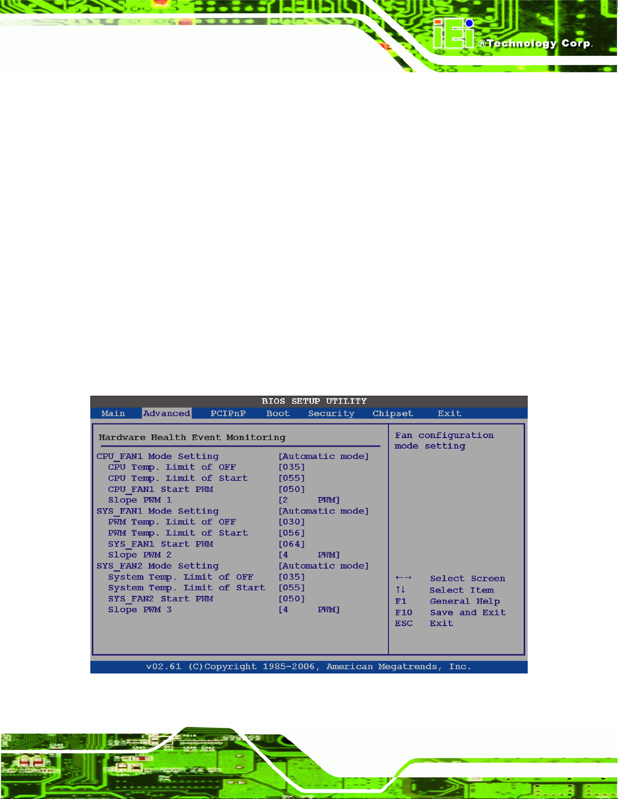
3.3.4 Hardware Health Configuration
The Hardware Health Configuration menu (5BIOS Menu 7 and BIOS Menu 8) shows the
operating temperature, fan speeds and system voltages.
BIOS Menu 7: Hardware Health Configuration
Page 45
Page 60

AFL-26/42A-9652 Panel PC
BIOS Menu 8: Hardware Health Configuration
Î FAN Mode Setting [Full On Mode]
Use the CPU FAN Mode Setting option to configure the second fan.
Î
Full On Mode DEFAULT
Î
Automatic mode
Î
PWM Manual mode
When the CPU FAN Mode Setting option is in the Automatic Mode, the following
parameters can be set.
CPU Temp. Limit of OFF
CPU Temp. Limit of Start
Fan is on all the time
Fan is off when the temperature is low
enough. Parameters must be set by the
user.
Pulse width modulation set manually
Page 46
CPU Fan Start PWM
Slope PWM 1
Page 61

AFL-26/42A-9652 Panel PC
When the CPU FAN Mode Setting option is in the PWM Manual Mode, the following
parameters can be set.
CPU Fan PWM control
Î Temp. Limit of OFF [000]
WARNING:
Setting this value too high may cause the fan to stop when the CPU is at
a high temperature and therefore cause the system to be damaged.
The CPU Temp. Limit of OFF option can only be set if the CPU FAN Mode Setting option
is set to Automatic Mode. Use the CPU Temp. Limit of OFF option to select the CPU
temperature at which the cooling fan should automatically turn off. To select a value, select
the CPU Temp. Limit of OFF option and enter a decimal number between 000 and 127.
The temperature range is specified below.
Minimum Value: 0°C
Maximum Value: 127°C
Î Temp. Limit of Start [020]
WARNING:
Setting this value too high may cause the fan to start only when the CPU
is at a high temperature and therefore cause the system to be
damaged.
The CPU Temp. Limit of Start option can only be set if the CPU FAN Mode Setting
option is set to Automatic Mode. Use the CPU Temp. Limit of Start option to select the
CPU temperature at which the cooling fan should automatically turn on. When the fan
starts, it rotates using the starting pulse width modulation (PWM) specified in the Fan 3
Start PWM option below. To select a value, select the CPU Temp. Limit of Start option
Page 47
Page 62

and enter a decimal number between 000 and 127. The temperature range is specified
below.
Minimum Value: 0°C
Maximum Value: 127°C
Î Fan Start PWM [070]
The Fan 3 Start PWM option can only be set if the CPU FAN Mode Setting option is set to
Automatic Mode. Use the Fan 3 Start PWM option to select the PWM mode the fan starts
to rotate with after the temperature specified in the Temperature 3 Limit of Start is
exceeded. The Super I/O chipset supports 128 PWM modes. To select a value, select the
Fan 3 Start PWM option and enter a decimal number between 000 and 127. The
temperature range is specified below.
PWM Minimum Mode: 0
AFL-26/42A-9652 Panel PC
PWM Maximum Mode: 127
Î Slope PWM [0.5 PWM]
The Slope PWM 1 option can only be set if the CPU FAN Mode Setting option is set to
Automatic Mode. Use the Slope PWM 1 option to select the linear rate at which the PWM
mode increases with respect to an increase in temperature. A list of available options is
shown below:
0 PWM
1 PWM
2 PWM
4 PWM
8 PWM
16 PWM
32 PWM
64 PWM
Page 48
The following system parameters and values are shown. The system parameters that are
monitored are:
System Temperatures: The following system temperatures are monitored
Page 63

AFL-26/42A-9652 Panel PC
o CPU temperature
o PWM temperature
o System temperature
Fan Speeds: The CPU cooling fan speed is monitored.
o CPU fan speed
o First system fan speed
Voltages: The following system voltages are monitored
o CPU Core
o +1.8 V
o +3.30 V
o +5.00 V
o +12.0 V
o +1.05 V
o +1.5 V
o 5 VSB
o VBAT
Page 49
Page 64
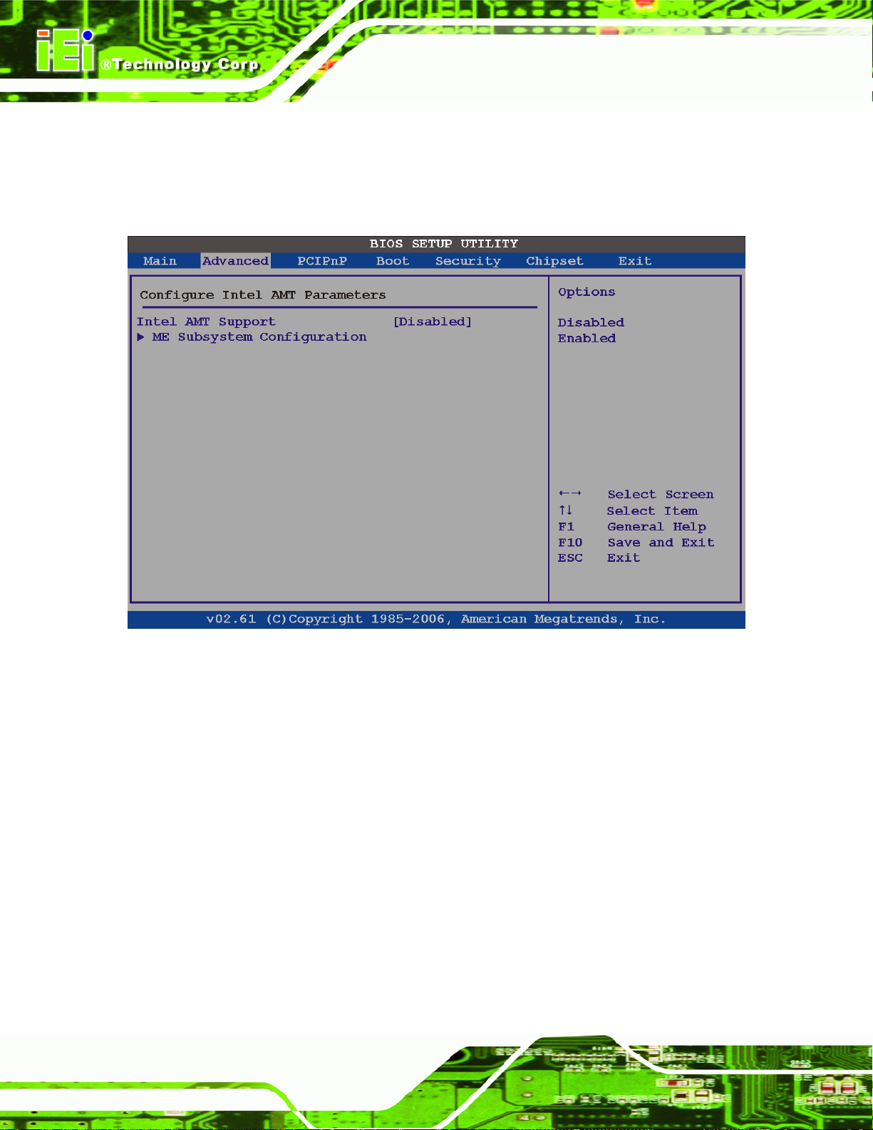
3.3.5 Intel AMT Configuration
The Intel AMT Configuration menu (BIOS Menu 9) configures the Intel® Active
Management Technology (AMT) options.
AFL-26/42A-9652 Panel PC
BIOS Menu 9: Intel AMT Configuration
Î Intel AMT Support [Enable]
Use the Intel AMT Support option to enable or disable the Intel AMT support.
Î
Disabled
Î
Enabled DEFAULT
Page 50
The Intel® AMT function is disabled.
The Intel® AMT function is enabled.
Page 65

AFL-26/42A-9652 Panel PC
3.3.5.1 ME Subsystem Configuration
The ME Subsystem Configuration menu (BIOS Menu 24) allows the AMT subsystem
(Management Engine, ME) and Host Embedded Controller Interface (HECI) driver options
to be configured.
BIOS Menu 10: ME Subsystem Configuration
Î BootBlock HECI Message [Enabled]
Use the BootBlock HECI Message option to enable or disable HECI message when
booting up the system.
Î
Disabled
Î
Enabled DEFAULT
The HECI message is disabled when booting up the
system.
The HECI message is enabled when booting up the
system.
Page 51
Page 66

Î HECI Message [Enabled]
Use the HECI Message BIOS option to enable or disable HECI message.
AFL-26/42A-9652 Panel PC
Î
Disabled
Î
Enabled DEFAULT
Î End Of Post S5 HECI Message [Enabled]
Use the End Of Post S5 HECI Message option to enable or disable HECI message when
the system is in the off (S5) state.
Î
Disabled
Î
Enabled DEFAULT
Î ME-HECI [Enabled]
The ME-HECI option is enabled by default and cannot be changed.
Î ME-IDER [Disabled]
Use the ME-IDER option to enable or disable the IDE-Redirection (IDE-R) function on an
The HECI message disabled.
The HECI message enabled.
The HECI message is disabled when the system is off.
The HECI message enabled when the system is off.
AMT-capable system.
Î
Disabled DEFAULT
Î
Enabled
Î ME-KT [Disabled]
Use the ME-KT option to enable or disable the Keyboard and Text redirection (KT) function
on an AMT-capable system. KT is also known as Serial-Over-Lan (SOL).
Î
Disabled DEFAULT
Page 52
The IDE-R function is disabled.
The IDE-R function allows an AMT-capable client system
to access IDE devices and load OS from a management
system. When an IDE-R session is established, the
virtual drives are shown in the system.
The KT function of the ME is disabled.
Page 67
AFL-26/42A-9652 Panel PC
Î
Enabled
The KT function allows a management system to control
an Intel® AMT client system remotely. The keyboard
interface of a managed client system, such as BIOS
menu, is displayed through the management system.
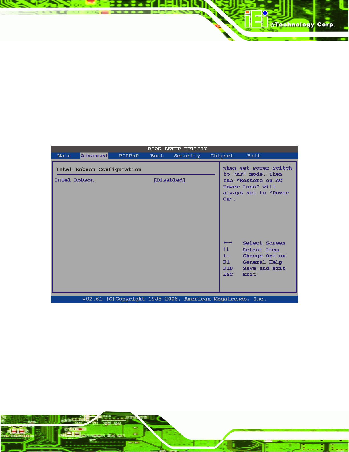
3.3.6 Intel Robson Configuration
The Intel Robson Configuration menu (BIOS Menu 15) allows the Intel® Robson
Technology option to be configured.
BIOS Menu 11: Intel Robson Configuration
Î Intel Robson [Disabled]
Use the Intel Robson BIOS option to enable or disable the Intel® Robson Technology
feature.
Î
Disabled DEFAULT
Î
Enabled
Disables the Intel® Robson feature
Enables the Intel® Robson feature
Page 53
Page 68

3.3.7 Remote Configuration
Use the Remote Access Configuration menu (BIOS Menu 12) to configure remote
access parameters. The Remote Access Configuration is an AMIBIOS feature and
allows a remote host running a terminal program to display and configure the BIOS
settings.
AFL-26/42A-9652 Panel PC
BIOS Menu 12: Remote Access Configuration
Î Remote Access [Disabled]
Use the Remote Access option to enable or disable access to the remote functionalities of
the system.
Î
Disabled DEFAULT
Page 54
Remote access is disabled.
Page 69

AFL-26/42A-9652 Panel PC
Î
Enabled
Î Serial Port Number [COM1]
Use the Serial Port Number option allows to select the serial port used for remote access.
Î
COM1 DEFAULT
Î
COM2
Remote access configuration options shown below
appear:
- Serial Port Number
- Serial Port Mode
- Flow Control
- Redirection after BIOS POST
- Terminal Type
- VT-UTF8 Combo Key Support
These configuration options are discussed below.
System is remotely accessed through COM1
System is remotely accessed through COM2
NOTE: Make sure the selected COM port is enabled through the Super I/O configuration
menu.
Î Base Address, IRQ [2F8h,3]
The Base Address, IRQ option cannot be configured and only shows the interrupt address
of the serial port listed above.
Î Serial Port Mode [115200 8,n,1]
Use the Serial Port Mode option to select baud rate through which the console redirection
is made. The following configuration options are available
115200 8,n,1 D
57600 8,n,1
38400 8,n,1
19200 8,n,1
09600 8,n,1
EFAULT
Page 55
Page 70

NOTE:
Identical baud rate setting musts be set on the host (a management
computer running a terminal software) and the slave
Î Flow Control [None]
Use the Flow Control option to report the flow control method for the console redirection
application.
AFL-26/42A-9652 Panel PC
Î
None DEFAULT
Î
Hardware
Î
Software
Î Redirection After BIOS POST [Always]
Use the Redirection After BIOS POST option to specify when console redirection should
occur.
Î
Disabled
Î
Boot Loader
Î
Always DEFAULT
Î Terminal Type [ANSI]
No control flow,
Hardware is set as the console redirection
Software is set as the console redirection
The console is not redirected after POST
Redirection is active during POST and during Boot
Loader
Redirection is always active (Some OSes may not
work if set to Always)
Page 56
Use the Terminal Type BIOS option to specify the remote terminal type.
Î
ANSI DEFAULT
Î
VT100
Î
VT-UTF8
The target terminal type is ANSI
The target terminal type is VT100
The target terminal type is VT-UTF8
Page 71

AFL-26/42A-9652 Panel PC
Î VT-UTF8 Combo Key Support [Disabled]
Use the VT-UFT8 Combo Key Support option to enable additional keys that are not
provided by VT100 for the PC 101 keyboard.
The VT100 Terminal Definition is the standard convention used to configure and conduct
emergency management tasks with UNIX-based servers. VT100 does not support all keys
on the standard PC 101-key layout, however. The VT-UTF8 convention makes available
additional keys that are not provided by VT100 for the PC 101 keyboard.
Î
Disabled DEFAULT
Î
Enabled
Î Sredir Memory Display Delay [Disabled]
Use the Sredir Memory Display Delay option to select the delay before memory
information is displayed. Configuration options are listed below
No Delay D
Delay 1 sec
Delay 2 sec
Delay 4 sec
Disables the VT-UTF8 terminal keys
Enables the VT-UTF8 combination key. Support for
ANSI/VT100 terminals
EFAULT
Page 57
Page 72

3.3.8 USB Configuration
Use the USB Configuration menu (5BIOS Menu 13) to read USB configuration information
and configure the USB settings.
AFL-26/42A-9652 Panel PC
BIOS Menu 13: USB Configuration
Î USB Function [Enabled]
Use the USB Function option to enable or disable the USB controllers.
Î
Disabled
Î
Enabled DEFAULT
Î Legacy USB Support [Enabled]
Use the Legacy USB Support BIOS option to enable USB mouse and USB keyboard
support.
Page 58
USB controllers are enabled
USB controllers are disabled
Page 73

AFL-26/42A-9652 Panel PC
Normally if this option is not enabled, any attached USB mouse or USB keyboard does not
become available until a USB compatible operating system is fully booted with all USB
drivers loaded. When this option is enabled, any attached USB mouse or USB keyboard
can control the system even when there is no USB driver loaded onto the system.
Î
Disabled
Î
Enabled DEFAULT
Î
Auto
Î USB 2.0 Controller [Enabled]
The USB 2.0 Controller BIOS option enables or disables the USB 2.0 controller
Î
Disabled
Î
Enabled DEFAULT
Î USB2.0 Controller Mode [HiSpeed]
The USB2.0 Controller Mode BIOS option sets the speed of the USB2.0 controller.
Î
FullSpeed
Legacy USB support disabled
Legacy USB support enabled
Legacy USB support disabled if no USB devices are
connected
USB function disabled
USB function enabled
The controller is capable of operating at full speed
12 Mb/s
Î
HiSpeed DEFAULT
The controller is capable of operating at high speed
480 Mb/s
Page 59
Page 74

3.3.9 Power Configuration
The Power Configuration menu (5BIOS Menu 14) configures the Advanced Configuration
and Power Interface (ACPI) and Power Management (APM) options.
AFL-26/42A-9652 Panel PC
Page 60
BIOS Menu 14: Power Configuration
Page 75
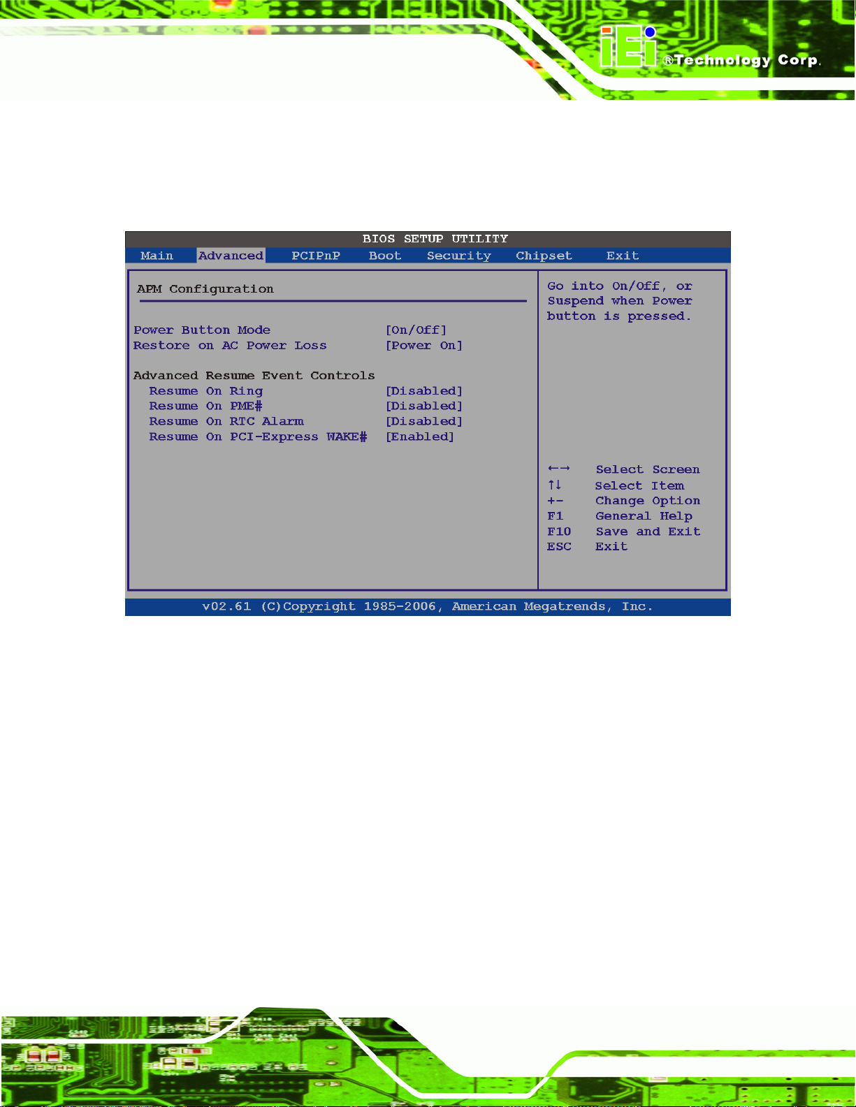
AFL-26/42A-9652 Panel PC
3.3.9.1 APM Configuration
The APM Configuration menu (BIOS Menu 15) allows the advanced power management
options to be configured.
BIOS Menu 15: Advanced Power Management Configuration
Î Power Button Mode [On/Off]
Use the Power Button Mode BIOS to specify how the power button functions.
Î
On/Off DEFAULT
Î
Suspend
Î Restore on AC Power Loss [Last State]
Use the Restore on AC Power Loss BIOS option to specify what state the system returns
to if there is a sudden loss of power to the system.
When the power button is pressed the system is either
turned on or off
When the power button is pressed the system goes into
suspend mode
Page 61
Page 76

AFL-26/42A-9652 Panel PC
Î
Power Off
Î
Power On
Î
Last State DEFAULT
Î Resume on Ring [Disabled]
Use the Resume on Ring BIOS option to enable activity on the RI (ring in) modem line to
rouse the system from a suspend or standby state. That is, the system will be roused by an
incoming call on a modem.
Î
Disabled DEFAULT
Î
Enabled
Î Resume on PME# [Disabled]
Use the Resume on PME# BIOS option to option to enable activity on the PCI PME (power
The system remains turned off
The system turns on
The system returns to its previous state. If it was on, it
turns itself on. If it was off, it remains off.
Wake event not generated by an incoming call
Wake event generated by an incoming call
management event) controller to rouse the system from a suspend or standby state.
Î
Disabled DEFAULT
Î
Enabled
Î Resume On RTC Alarm [Disabled]
Use the Resume On RTC Alarm option to specify the time the system should be roused
from a suspended state.
Î
Disabled DEFAULT
Wake event not generated by PCI PME controller
activity
Wake event generated by PCI PME controller activity
The real time clock (RTC) cannot generate a wake
event
Page 62
Page 77

AFL-26/42A-9652 Panel PC
Î
Enabled
Î Resume on PCI-Express WAKE# [Enabled]
Use the Resume PCI-Express WAKE# BIOS option to enable activity on the PCI-Express
WAKE# signal to rouse the system from a suspend or standby state.
Î
Disabled
Î
Enabled DEFAULT
If selected, the following appears with values that can
be selected:
- RTC Alarm Date (Days)
- RTC Alarm Time
After setting the alarm, the computer turns itself on
from a suspend state when the alarm goes off.
Wake event not generated by PCI-Express WAKE#
signal activity
Wake event generated by PCI-Express WAKE# signal
activity
Page 63
Page 78
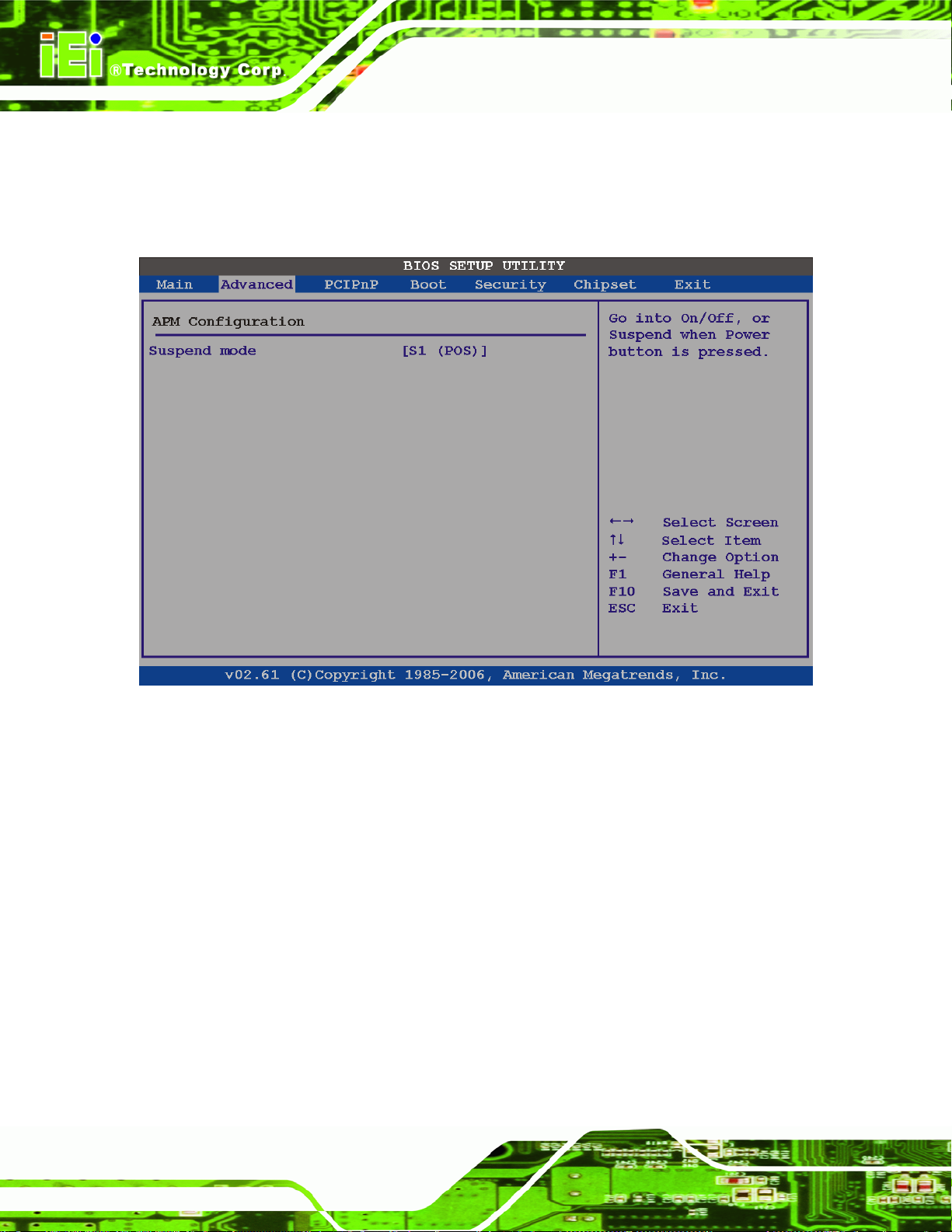
3.3.9.2 ACPI Configuration
Use the ACPI Configuration menu (BIOS Menu 16) to select the ACPI state when the
system is suspended.
AFL-26/42A-9652 Panel PC
BIOS Menu 16: ACPI Configuration
Î Suspend Mode [S1(POS)]
Use the Suspend Mode option to specify the sleep state the system enters when it is not
being used.
Î
S1 (POS) DEFAULT
3.4 PCI/PnP
Use the PCI/PnP menu (5BIOS Menu 17) to configure advanced PCI and PnP settings.
Page 64
The system enters S1(POS) sleep state. The system
appears off. The CPU is stopped; RAM is refreshed; the
system is running in a low power mode.
Page 79
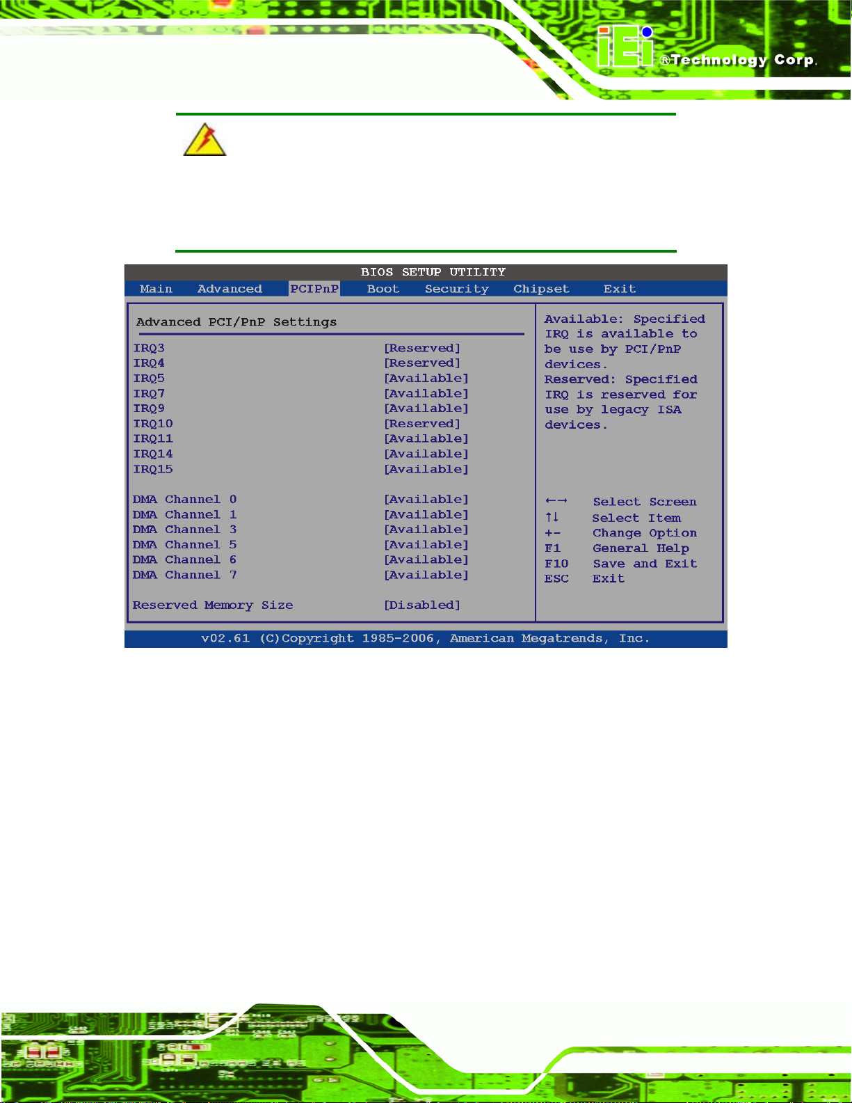
AFL-26/42A-9652 Panel PC
WARNING:
Setting wrong values for the BIOS selections in the PCIPnP BIOS menu
may cause the system to malfunction.
BIOS Menu 17: PCI/PnP Configuration
Î IRQ# [Available]
Use the IRQ# address to specify what IRQs can be assigned to a particular peripheral
device.
Î
Available DEFAULT
Î
Reserved
Available IRQ addresses are:
The specified IRQ is available to be used by PCI/PnP
devices
The specified IRQ is reserved for use by Legacy ISA
devices
Page 65
Page 80

IRQ3
IRQ4
IRQ5
IRQ7
IRQ9
IRQ10
IRQ 11
IRQ 14
IRQ 15
Î DMA Channel# [Available]
Use the DMA Channel# option to assign a specific DMA channel to a particular PCI/PnP
device.
AFL-26/42A-9652 Panel PC
Î
Available DEFAULT
Î
Reserved
Available DMA Channels are:
DM Channel 0
DM Channel 1
DM Channel 3
DM Channel 5
DM Channel 6
DM Channel 7
Î Reserved Memory Size [Disabled]
Use the Reserved Memory Size BIOS option to specify the amount of memory that should
The specified DMA is available to be used by
PCI/PnP devices
The specified DMA is reserved for use by Legacy ISA
devices
Page 66
be reserved for legacy ISA devices.
Î
Disabled DEFAULT
Î
16K
No memory block reserved for legacy ISA devices
16 KB reserved for legacy ISA devices
Page 81
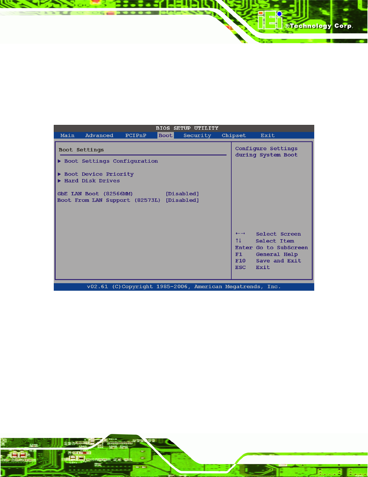
AFL-26/42A-9652 Panel PC
Î
Î
3.5 Boot
Use the Boot menu (5BIOS Menu 18) to configure system boot options.
32K
64K
32 KB reserved for legacy ISA devices
54 KB reserved for legacy ISA devices
BIOS Menu 18: Boot
Î GbE LAN Boot (82566MM) [Disabled]
The GbE LAN Boot (82566MM) option enables the system to be booted through LAN1.
Î
Disabled DEFAULT
Î
Enabled DEFAULT
Cannot be booted remotely through LAN1
Can be booted remotely through LAN1
Page 67
Page 82

Î Boot From LAN Support (82573L) [Disabled]
The BOOT From LAN Support (82573L) option enables the system to be booted through
LAN2.
AFL-26/42A-9652 Panel PC
Î
Disabled DEFAULT
Î
Enabled DEFAULT
Cannot be booted remotely through LAN2
Can be booted remotely through LAN2
3.5.1 Boot Settings Configuration
Use the Boot Settings Configuration menu (5BIOS Menu 18) to configure advanced system
boot options.
BIOS Menu 19: Boot Settings Configuration
Î Quick Boot [Enabled]
Use the Quick Boot BIOS option to make the computer speed up the boot process.
Î
Disabled
Page 68
No POST procedures are skipped
Page 83

AFL-26/42A-9652 Panel PC
Î
Enabled DEFAULT
Î Quiet Boot [Disabled]
Use the Quiet Boot BIOS option to select the screen display when the system boots.
Î
Disabled DEFAULT
Î
Enabled
Î AddOn ROM Display Mode [Force BIOS]
The AddOn ROM Display Mode option allows add-on ROM (read-only memory)
messages to be displayed.
Î
Force BIOS DEFAULT
Some POST procedures are skipped to decrease the
system boot time
Normal POST messages displayed
OEM Logo displayed instead of POST messages
Allows the computer system to force a third party
BIOS to display during system boot.
Î
Keep Current
Î Bootup Num-Lock [Off]
The Bootup Num-Lock BIOS option allows the Number Lock setting to be modified during
boot up.
Î
Off DEFAULT
Î
On
Does not enable the keyboard Number Lock automatically. To
use the 10-keys on the keyboard, press the Number Lock key
located on the upper left-hand corner of the 10-key pad. The
Number Lock LED on the keyboard lights up when the Number
Lock is engaged.
Allows the Number Lock on the keyboard to be enabled
automatically when the computer system boots up. This allows
the immediate use of the 10-key numeric keypad located on the
right side of the keyboard. To confirm this, the Number Lock
Allows the computer system to display the
information during system boot.
LED light on the keyboard is lit.
Page 69
Page 84

3.5.2 Boot Device Priority
Use the Boot Device Priority menu (5BIOS Menu 20) to specify the boot sequence from
the available devices. The following options are available:
st
1
Boot Device
nd
2
3
Boot Device
rd
Boot Device
AFL-26/42A-9652 Panel PC
Page 70
BIOS Menu 20: Boot Device Priority Settings
Page 85

AFL-26/42A-9652 Panel PC
3.6 Security
Use the Security menu (5BIOS Menu 21) to set system and user passwords.
BIOS Menu 21: Security
Î Change Supervisor Password
Use the Change Supervisor Password to set or change a supervisor password. The
default for this option is Not Installed. If a supervisor password must be installed, select
this field and enter the password. After the password has been added, Install appears next
to Change Supervisor Password.
Î Change User Password
Use the Change User Password to set or change a user password. The default for this
option is Not Installed. If a user password must be installed, select this field and enter the
password. After the password has been added, Install appears next to Change User
Password.
Page 71
Page 86

3.7 Chipset
Use the Chipset menu (5BIOS Menu 22) to access the Northbridge and Southbridge
configuration menus
AFL-26/42A-9652 Panel PC
WARNING!
Setting the wrong values for the Chipset BIOS selections in the Chipset
BIOS menu may cause the system to malfunction.
Page 72
BIOS Menu 22: Chipset
Page 87

AFL-26/42A-9652 Panel PC
3.7.1 Northbridge Chipset Configuration
Use the Northbridge Chipset Configuration menu (5BIOS Menu 22) to configure the
Northbridge chipset settings.
BIOS Menu 23: Northbridge Chipset Configuration
Î Memory Remap Feature [Enabled]
The Memory Remap Feature is for systems with 4 GB or more of memory. The amount of
memory is incorrectly reported when 4 GB or more of memory is installed. This setting
allows the amount of memory to be correctly reported.
Î
Disabled
Î
Enabled DEFAULT
Î Memory Hole [Disabled]
The Memory Hole reserves the memory space between 15 MB and 16 MB for ISA
expansion cards that require a specified area of memory to work properly. If an older ISA
4 GB or more of memory is reported as less
Memory of any amount is reported correctly
Page 73
Page 88

expansion card is used, please refer to the documentation that came with the card to see if
it is necessary to reserve the space.
AFL-26/42A-9652 Panel PC
Î
Disabled DEFAULT
Î
Enabled
Î Internal Graphics Mode Select [Enable, 8 MB]
The Internal Graphic Mode Select option determines the amount of system memory that
can be used by the Internal graphics device.
Î
Disable
Î
Enable, 1 MB
Î
Enable, 8 MB DEFAULT
Î Boot Display Device [Auto]
The Boot Display Devi ce BIOS option selects the display device the system uses when it
boots. The available options are listed below:
Memory is not reserved for ISA expansion cards
Memory is reserved for ISA expansion cards
1 MB of memory used by internal graphics device
8 MB of memory used by internal graphics device
Auto D
CRT
LFP
Î Flat Panel Type
Use the Flat Panel Type to set the LCD panel resolution. This option should not need to be
changed from the default setting. Options are listed below.
640 x 480 18-bit
800 x 600 18-bit
1024 x 768 18-bit
1024 x 768 24-bit
1024 x 768 48-bit
1280 x 1024 48-bit
1600 x 1200 48-bit
EFAULT
Page 74
Page 89
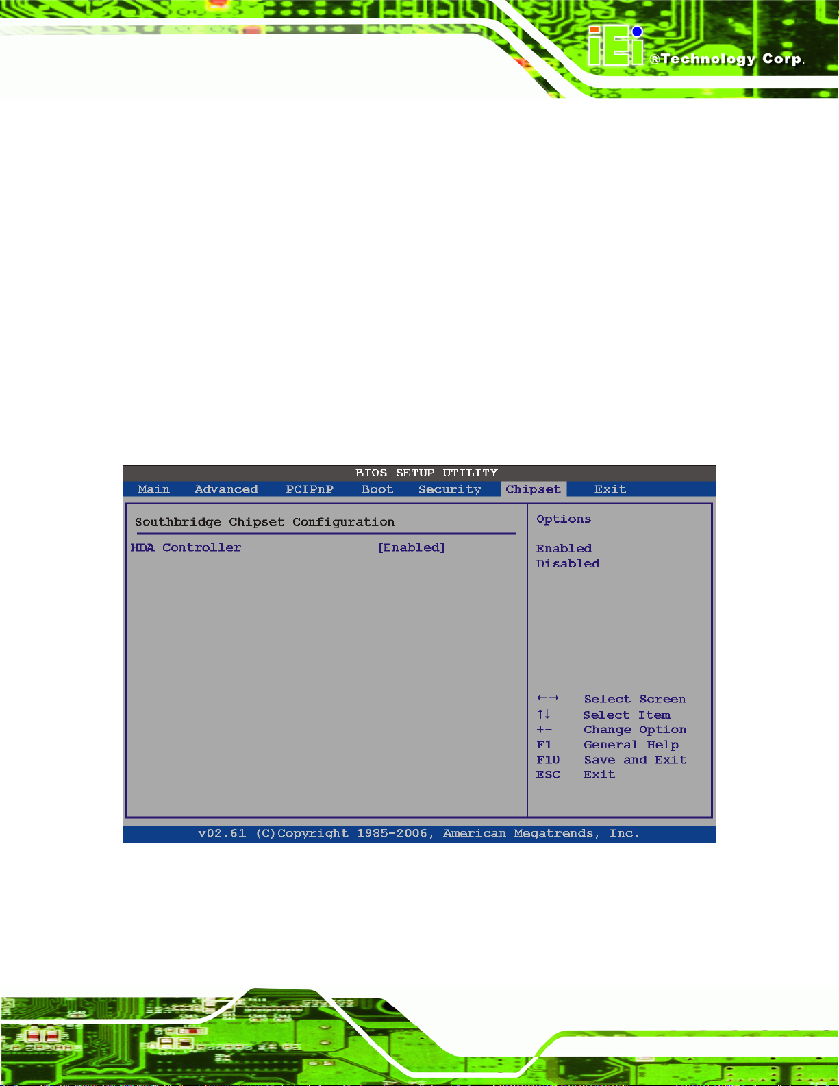
AFL-26/42A-9652 Panel PC
1280 x 768 18-bit
1280 x 800 18-bit
1366 x 768 24-bit
1440 x 900 36-bit
1440 x 900 48-bit
1680 x 1050 48-bit
1920 x 1080 48-bit
1920 x 1200 48-bit
by HARDWARE Default
3.7.2 Southbridge Configuration
The Southbri dge Configuration menu (5BIOS Menu 24) allows the Southbridge chipset to
be configured.
BIOS Menu 24: Southbridge Chipset Configuration
Î HDA Controller [All Disabled]
The HDA Controller option enables or disables the built-in sound device.
Page 75
Page 90
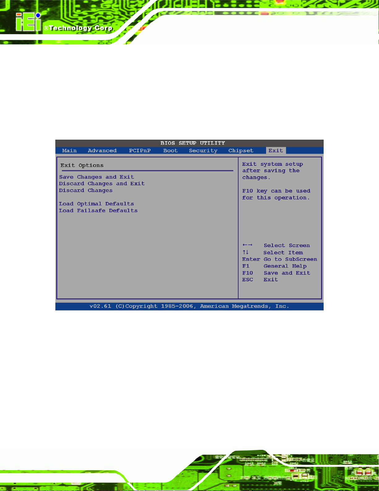
AFL-26/42A-9652 Panel PC
Î
Î
3.8 Exit
Use the Exit menu (5BIOS Menu 25) to load default BIOS values, optimal failsafe values
and to save configuration changes.
Enabled DEFAULT
Disabled
On-board sound is turned on
On-board sound is turned off
BIOS Menu 25: Exit
Î Save Changes and Exit
Use the Save Changes and Exit option to save the changes made to the BIOS options
and to exit the BIOS configuration setup program.
Î Discard Changes and Exit
Use the Discard Changes and Exit option to exit the BIOS configuration setup program
without saving the changes made to the system.
Page 76
Page 91

AFL-26/42A-9652 Panel PC
Î Discard Changes
Use the Discard Changes option to discard the changes and remain in the BIOS
configuration setup program.
Î Load Optimal Defaults
Use the Load Optimal Defaults option to load the optimal default values for each of the
parameters on the Setup menus. F9 key can be used for this operation.
Î Load Failsafe Defaults
Use the Load Failsafe Defaults option to load failsafe default values for each of the
parameters on the Setup menus. F8 key can be used for this operation.
Page 77
Page 92

AFL-26/42A-9652 Panel PC
Chapter
4
4 Driver Installation
Page 78
Page 93
AFL-26/42A-9652 Panel PC
4.1 Available Software Drivers
NOTE:
The content of the CD may vary throughout the life cycle of the product
and is subject to change without prior notice. Visit the IEI website or
contact technical support for the latest updates.
The following drivers can be installed on the system:
4.2 Chipset Driver ...................................................................................................... 79
4.3 Graphics Driver.................................................................................................... 83
4.4 LAN Driver ........................................................................................................... 88
4.5 Audio Driver .........................................................................................................92
4.6 Touch Panel Driver ..............................................................................................95
4.7 Keypad Utility Driver ............................................................................................99
4.8 Wireless LAN PCIe Mini Card Driver................................................................... 102
4.9 Bluetooth Driver................................................................................................... 106
4.10 Intel® AMT (HECI) Driver ..................................................................................112
Installation instructions are given below.
4.2 Chipset Driver
To install the chipset driver, please follow the steps below.
Page 79
Page 94
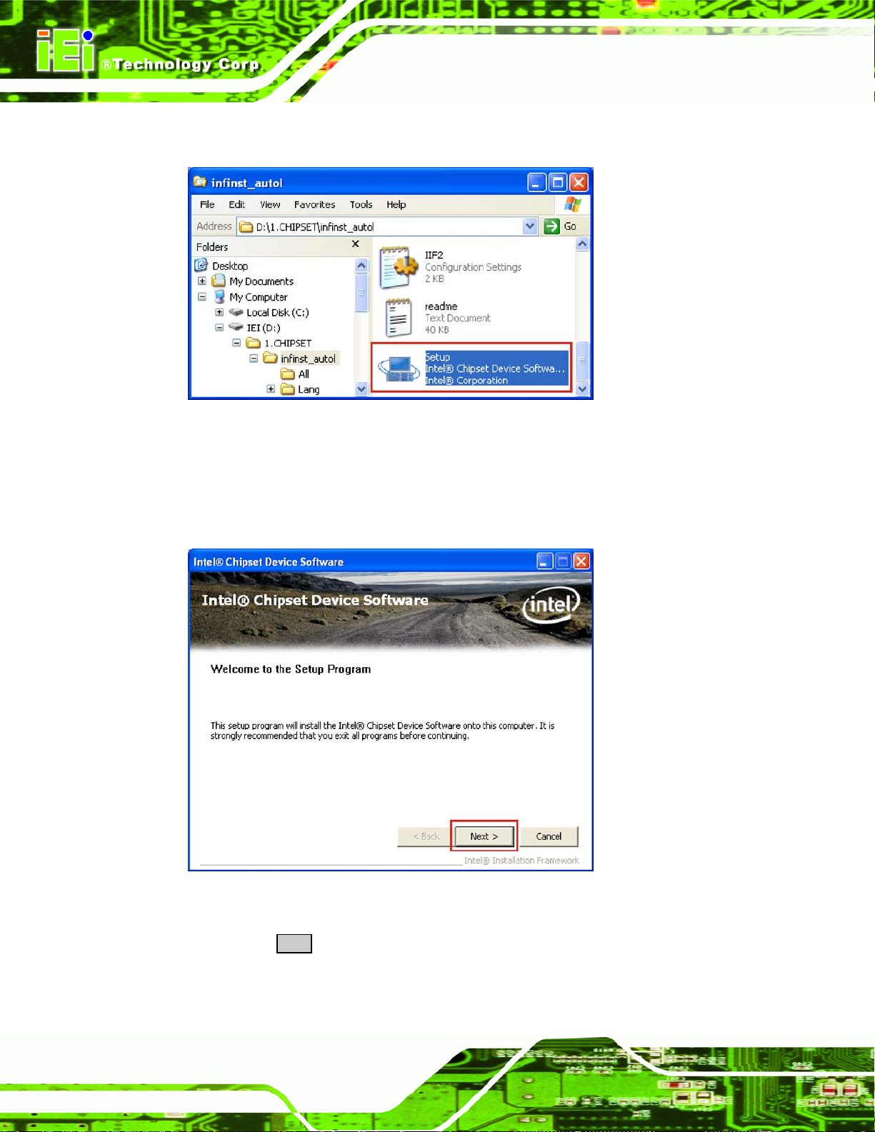
Step 16: In Windows Explorer, browse to "D:\1.Chipset\" Figure 4-1.
Figure 4-1: Chipset Driver Icon
AFL-26/42A-9652 Panel PC
Step 17: Double-click the SETUP icon to start the driver installation program (
Step 18: The chipset installation driver welcome screen in
Figure 4-2 appears.
Figure 4-1).
Page 80
Figure 4-2: Chipset Driver Welcome Screen
Step 19: Click NEXT to continue the installation process. (Figure 4-2)
Page 95
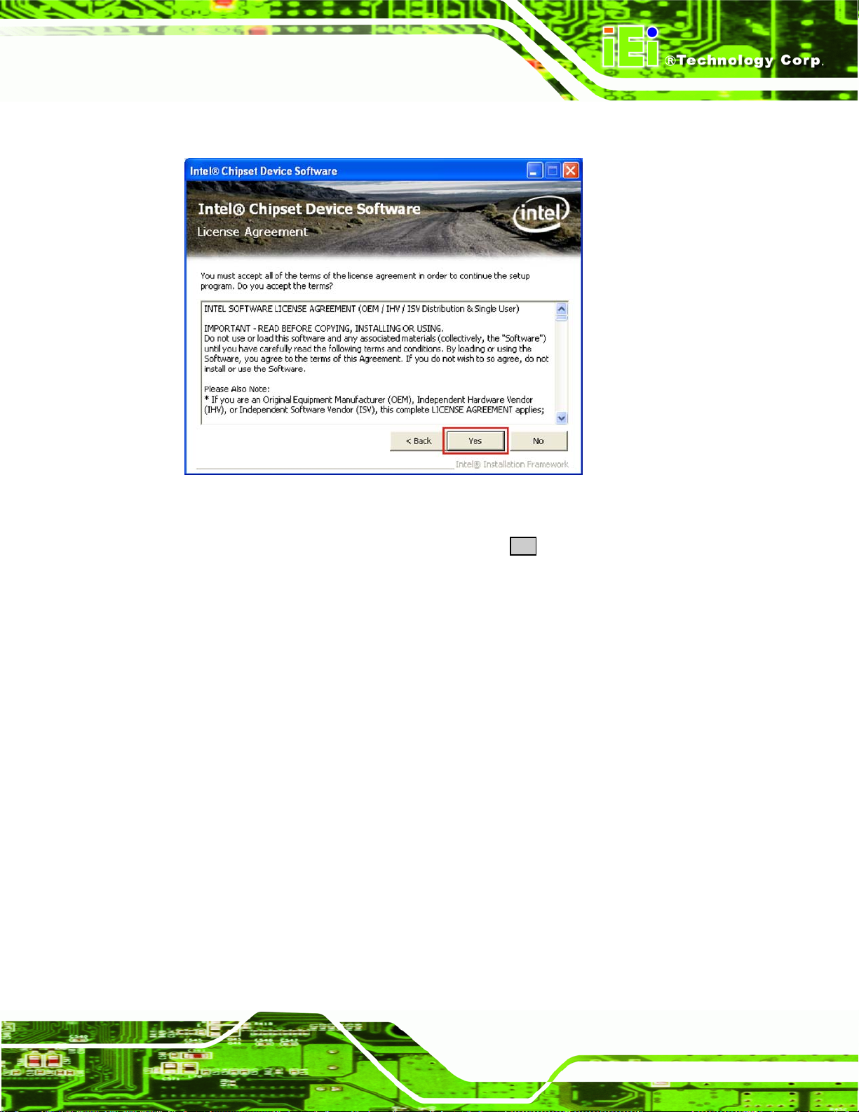
AFL-26/42A-9652 Panel PC
Step 20: The license agreement in Figure 4-3 appears.
Figure 4-3: Chipset Driver License Agreement
Step 21: Read the license agreement carefully. Click YES to accept the terms of the
license agreement and continue with the installation (Figure 4-3).
Page 81
Page 96

Step 22: The Readme File Information window appears (Figure 4-4).
AFL-26/42A-9652 Panel PC
Figure 4-4: Chipset Driver Readme File
Step 23: Click NEXT to continue the installation process (Figure 4-4).
Step 24: When the drivers are installed, the window in Figure 4-4 appears.
Page 82
Figure 4-5: Chipset Drivers Installed
Page 97

AFL-26/42A-9652 Panel PC
Step 25: Click NEXT to continue the installation process (Figure 4-5).
Step 26: The Setup is Complete window appears (Figure 4-6).
Figure 4-6: Chipset Driver Installed Drivers
Step 27: The driver installation is now finished. Click FINISH to complete the installation.Step 0:
4.3 Graphics Driver
To install the graphics driver, please follow the steps below.
Step 1: In Windows Explorer, browse to "D:\2.VGA\" (
Figure 4-7).
Figure 4-7: Graphics Driver Installation
Page 83
Page 98

Step 2: Double-click setup in Figure 4-7to begin the driver installation.
AFL-26/42A-9652 Panel PC
Step 3: The Graphics Driver Software information screen appears (
Figure 4-8: Graphics Driver Software
Figure 4-8).
Page 84
Page 99

AFL-26/42A-9652 Panel PC
Step 4: The Graphics Media Accelerator Driver welcome screen appears
Figure 4-9).
(
Figure 4-9: Graphics Media Accelerator Driver
Step 5: Click NEXT to continue with the graphics driver installation (Figure 4-9).
Page 85
Page 100
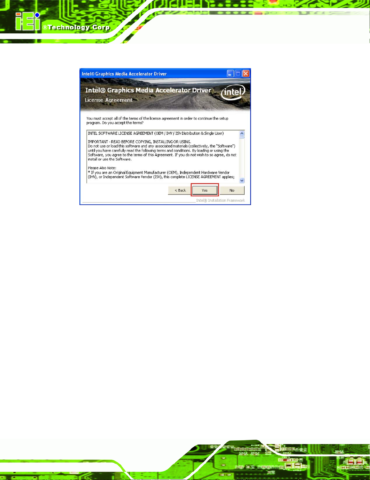
Step 6: The License Agreement windows appears (Figure 4-10).
AFL-26/42A-9652 Panel PC
Figure 4-10: Graphics License Agreement
Step 7: Click Yes to accept the license agreement and continue with the Intel® Graphics
Media Driver Installation (
Figure 4-10).
Page 86
 Loading...