

IEI Technology AFL2-17AB-H61-i3/PC-R12, AFL2-17AB-H61-i5/R-R12, AFL2-17A-H61-i5/PC-R12, AFL2-17A-H61-P/R-R12, AFL2-17AB-H61-P/R-R12 User Manual
...Page 1

AFL2-17A/AB-H61
Page I
IEI Technology Corp.
User Manual
AFL2-17A/AB-H61 Series
MODEL:
Flat Bezel Panel P C with 2nd Generation In tel® Core™ i7/ i5/ i3,
Pentium® and Celeron® processor, Touch Screen, Wi-Fi, USB,
Dual GbE LAN , RS-232/422/485, 1.3M pixel s Camera,
HD Audio and RoHS
Rev. 1.22 - 24 Ju ly, 2013
User Manual
Page 2
AFL2-17A/AB-H61
Page II
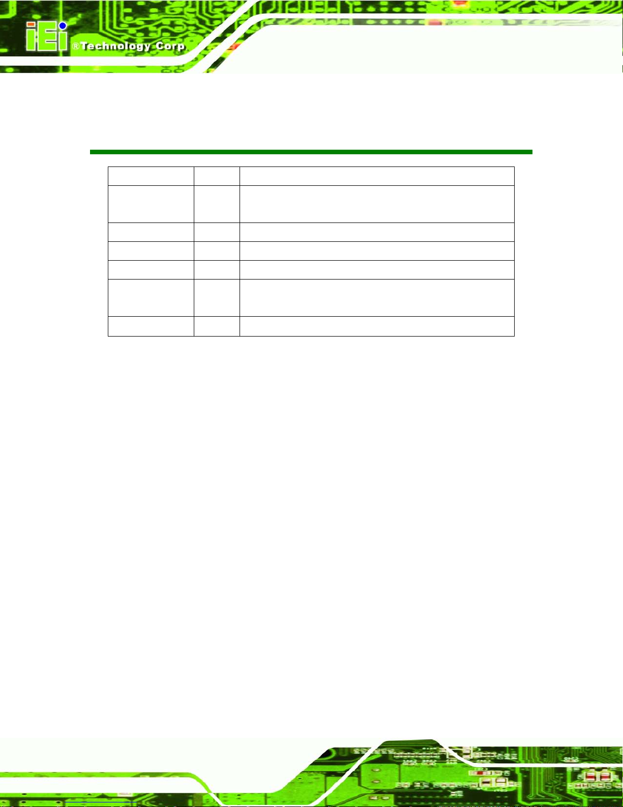
Revision
Date Version Changes
24 July, 2013 1.22 Update the Note for CPU temperature alert LED in Section 1.2.1.1: LED
Indicators
14 May, 2013 1.21 Update the mechanical keys to film keys
18 April, 2013 1.20 Add Section 1.2.1.2: LED light
4 January, 2013 1.11 Remove Section 5.6: PCI e Expansion Card Installation (Optional)
30 October, 2012 1.10 Model variations update
LED Light Bar update
17 October, 2012 1.00
Initial release
Page 3

AFL2-17A/AB-H61
Page III
Copyright
COP YRIGHT NOTICE
The information in this document is subject to change without prior notice in order to
improve reliabilit y, design and func tion and d oes not r epresent a com mitm ent on the par t
of the manufacturer.
In no event will the manufacturer be liable for direct, indirect, special, incidental, or
consequential damages arising out of the use or inability to use the product or
documentation, even if advised of the possibility of such damages.
This document contains proprietary information protected by copyright. All rights are
reserved. No part of this manual may be reproduced by any mechanical, e lectronic, or
other means in any form without prior written permission of the manufacturer.
TRADEMARKS
All registered tradem ark s and produc t nam es ment ioned here in are us ed for identif icatio n
purposes only and m ay be trademarks and/or registe red trademarks of their respecti ve
owners.
Page 4

AFL2-17A/AB-H61
Page IV
Table of Contents
1 INTRODUCTION .......................................................................................................... 1
1.1 AFL2-17A/AB-H61 FLAT BEZEL PANEL PC OVERVIEW ............................................ 2
1.1.1 Model Variations ................................................................................................ 3
1.1.2 Features ............................................................................................................. 3
1.1.3 Light Fanless Technology Design ...................................................................... 4
1.2 EXTERNAL OVERVIEW ................................................................................................ 5
1.2.1 Front Panel ........................................................................................................ 5
1.2.1.1 LED Indicators ............................................................................................ 5
1.2.1.2 LED Light ................................................................................................... 7
1.2.1.3 Function Keys ............................................................................................. 8
1.2.2 Rear Panel ......................................................................................................... 9
1.2.3 Bottom Panel ...................................................................................................... 9
1.2.4 Left Side Panel ................................................................................................. 10
1.2.5 Right Side Panel ................................................................................................ 11
1.3 INTERNAL OVERVIEW ................................................................................................ 11
1.4 SYSTEM SPECIFICATIONS .......................................................................................... 12
2 LED LIGHT BAR (OPTIONAL) ............................................................................... 14
2.1 OVERVIEW................................................................................................................ 15
2.2 IEI LED LIGHT BAR DISPLAY SIMULATOR ............................................................... 15
2.3 IEI LED RUN ............................................................................................................ 24
2.4 LED CONTROL API .................................................................................................. 24
2.4.1 Introduction ...................................................................................................... 24
2.4.1.1 Programming Language Support .............................................................. 24
2.4.1.2 Application Content .................................................................................. 24
2.4.2 LED Control API Functions ............................................................................. 25
2.4.2.1 LIGHTBAR_DriverInit ............................................................................ 25
2.4.2.2 LIGHTBAR_DriverUninit ........................................................................ 25
2.4.2.3 LIGHTBAR_DeviceInit ........................................................................... 25
2.4.2.4 LIGHTBAR_DeviceClose ........................................................................ 26
2.4.2.5 LIGHTBAR_Brightness_Single ............................................................... 26
Page 5
AFL2-17A/AB-H61
Page V
2.4.2.6 LIGHTBAR_BLNK_Settings ................................................................... 26
2.4.2.7 LIGHTBAR_BLNK_Type........................................................................ 27
2.4.2.8 LIGHTBAR_LED_ModeSet .................................................................... 27
2.4.3 Structures ......................................................................................................... 28
2.4.3.1 _LED_COLOR_INFO .............................................................................. 28
2.4.3.2 _LED_BLNK_SET ................................................................................... 28
2.4.3.3 _LED_BLNK_SET ................................................................................... 29
2.4.3.4 _LED_MODE_SETTINGS ...................................................................... 30
2.4.4 Programming Example .................................................................................... 30
2.4.4.1 Turn on LED - single ................................................................................ 30
2.4.4.2 Turn on LED - multiple............................................................................. 31
2.4.4.3 LED Blink - 1 ............................................................................................ 33
2.4.4.4 LED Blink - 2 ............................................................................................ 34
3 DETAILED SPECIFICATIONS ................................................................................ 37
3.1 DIMENSIONS ............................................................................................................. 38
3.2 INTEL® CORE™ DESKTOP PROCESSOR .................................................................... 39
3.3 MOTHERBOARD COMPONENTS ................................................................................. 39
3.3.1 Memory Capacity ............................................................................................. 39
3.3.2 Storage Capacity .............................................................................................. 39
3.4 EXTERNAL PERIPHERAL INTERFACE CONNECTORS ................................................... 39
3.4.1 Serial Port Connectors .................................................................................... 39
3.4.2 LAN Connectivity ............................................................................................. 40
3.4.3 External USB Connectors ................................................................................ 41
3.5 AUDIO ...................................................................................................................... 42
3.5.1 Audio Codec Controller ................................................................................... 42
3.5.2 Stereo Speakers ................................................................................................ 42
4 UNPACKING ............................................................................................................... 43
4.1 UNPACKING .............................................................................................................. 44
4.1.1 Packing List ..................................................................................................... 44
5 INSTALLATION ......................................................................................................... 48
5.1 ANTI-STATIC PRECAUTIONS ...................................................................................... 49
5.2 INSTALLATION PRECAUTIONS ................................................................................... 49
5.3 INST ALLATION AND CONFIGURATION STEPS ............................................................. 50
Page 6

AFL2-17A/AB-H61
Page VI
5.4 HDD INSTALLATION ................................................................................................. 50
5.5 K-TYPE TEMPERATURE SENSOR INSTALLATION ....................................................... 53
5.6 RFID READER (OPTIONAL) ...................................................................................... 54
5.7 DVD-ROM INSTALLATION (OPTIONAL) .................................................................. 55
5.8 AT/ATX MODE SELECTION ...................................................................................... 57
5.8.1 AT Power Mode ................................................................................................ 58
5.8.2 ATX Power Mode ............................................................................................. 58
5.9 CLEAR CMOS .......................................................................................................... 58
5.10 RESET THE SYSTEM ................................................................................................ 59
5.11 POWERING ON THE SYSTEM ................................................................................... 59
5.12 POWERING OFF THE SYSTEM .................................................................................. 60
5.13 MOUNTING THE SYSTEM ........................................................................................ 60
5.13.1 Wall Mounting ................................................................................................ 60
5.13.2 Panel Mounting .............................................................................................. 64
5.13.3 Stand Mounting .............................................................................................. 65
5.13.4 Arm Mounting ................................................................................................ 65
5.14 EXTERNAL PERIPHERAL DEVICE CONNECTION ...................................................... 66
5.14.1 Audio Connection ........................................................................................... 67
5.14.2 HDMI Device Connection .............................................................................. 68
5.14.3 LAN Connection ............................................................................................. 70
5.14.4 Serial Device Connection .............................................................................. 71
5.14.5 USB Device Connection ................................................................................. 73
5.14.6 VGA Monitor Connection .............................................................................. 75
6 SYSTEM MOTHERBOARD ..................................................................................... 77
6.1 OVERVIEW................................................................................................................ 78
6.1.1 Layout .............................................................................................................. 78
6.1.2 Peripheral Interface Connectors ..................................................................... 79
6.2 INTERNAL PERIPHERAL CONNECTORS ...................................................................... 81
6.2.1 Auto-Dimming Connector ................................................................................ 81
6.2.2 Battery Connector ............................................................................................ 82
6.2.3 BIOS Programming Connector ........................................................................ 83
6.2.4 Bluetooth Connector ........................................................................................ 84
6.2.5 CPU Fan Connector ........................................................................................ 84
6.2.6 DDR3 SO-DIMM Slots .................................................................................... 85
Page 7

AFL2-17A/AB-H61
Page VII
6.2.7 Debug Port Connector ..................................................................................... 86
6.2.8 Digital Microphone Connector ........................................................................ 87
6.2.9 EC Debug Connector ....................................................................................... 88
6.2.10 EC Programming Connector ......................................................................... 89
6.2.11 Hotkey Connector ........................................................................................... 90
6.2.12 Hotkey LED Connector .................................................................................. 90
6.2.13 JSATA Connector ........................................................................................... 91
6.2.14 K Type Thermocouple Connector .................................................................. 92
6.2.15 LVDS Connector ............................................................................................ 94
6.2.16 LVDS Backlight Inverter Connector .............................................................. 95
6.2.17 LED Connector .............................................................................................. 96
6.2.18 Light Bar Connectors ..................................................................................... 97
6.2.19 LOGO LED Connector .................................................................................. 98
6.2.20 Mini USB Connector ...................................................................................... 99
6.2.21 PCIe Mini Card Slot .................................................................................... 101
6.2.22 Power Button Connector .............................................................................. 102
6.2.23 RFID Connector ........................................................................................... 102
6.2.24 SATA 3Gb/s Drive Connectors ..................................................................... 103
6.2.25 SATA Power Connector ................................................................................ 104
6.2.26 Speaker Connector ....................................................................................... 105
6.2.27 Touch panel connector (5-wire resistive type) ............................................. 106
6.2.28 Touch panel connector (projected capacitive type) ..................................... 107
6.2.29 TPM Connector ............................................................................................ 108
6.2.30 Web Camera Connector ............................................................................... 109
6.3 JUMPER SETTINGS ................................................................................................... 111
6.3.1 LVDS Voltage Selection ................................................................................... 111
6.3.2 LCD panel selection ........................................................................................ 112
7 SYSTEM MAINTENANCE ...................................................................................... 114
7.1 SYSTEM MAINTENANCE INTRODUCTION ................................................................. 115
7.2 ANTI-STATIC PRECAUTIONS ..................................................................................... 115
7.3 TURN OFF THE POWER ............................................................................................. 116
7.4 OPENIN G THE SYSTEM ............................................................................................. 116
7.4.1 Removing the Back Cover ............................................................................... 116
7.4.2 Removing the Internal Aluminum Cover ......................................................... 117
Page 8
AFL2-17A/AB-H61
Page VIII
7.5 REPLACING COMPONENTS ....................................................................................... 118
7.5.1 Memory Module Replacement ........................................................................ 118
7.5.2 WLAN Card Replacement ............................................................................... 119
7.6 REINSTALLING THE COVERS ................................................................................... 122
8 BIOS SETUP .............................................................................................................. 123
8.1 INTRODUCTION ....................................................................................................... 124
8.1.1 Starting Setup ................................................................................................. 124
8.1.2 Using Setup .................................................................................................... 124
8.1.3 Getting Help ................................................................................................... 125
8.1.4 Unable to Reboot after Configuration Changes ............................................ 125
8.1.5 BIOS Menu Bar .............................................................................................. 125
8.2 MAIN ...................................................................................................................... 126
8.3 ADVANCED ............................................................................................................. 127
8.3.1 ACPI Settings ................................................................................................. 128
8.3.2 RTC Wake Settings ......................................................................................... 129
8.3.3 T rusted Computing ......................................................................................... 130
8.3.4 CPU Configuration ........................................................................................ 131
8.3.4.1 CPU Information ..................................................................................... 132
8.3.5 SATA Configuration ....................................................................................... 134
8.3.6 Intel TXT (LT) Configuration ......................................................................... 135
8.3.7 USB Configuration ......................................................................................... 136
8.3.8 F81216 Super IO Configuration .................................................................... 138
8.3.8.1 Serial Port n Configuration ..................................................................... 138
8.3.9 H/W Monitor .................................................................................................. 142
8.3.10 Serial Port Console Redirection .................................................................. 144
8.4 IEI FEATURE ........................................................................................................... 145
8.5 CHIPSET ................................................................................................................. 146
8.5.1 Northbridge Configuration ............................................................................ 147
8.5.2 Southbridge Configuration ............................................................................ 148
8.5.3 Integrated Graphics ....................................................................................... 152
8.5.4 ME Subsystem ................................................................................................ 153
8.6 BOOT ...................................................................................................................... 155
8.7 SECURITY ............................................................................................................... 157
8.8 SAVE & EXIT .......................................................................................................... 158
Page 9

AFL2-17A/AB-H61
Page IX
9 SOFTWARE DRIVERS ............................................................................................ 160
9.1 AVAILABLE SOFTWARE DRIVERS ............................................................................ 161
9.2 STARTING THE DRIVER PROGRAM .......................................................................... 161
9.3 CHIPSET DRIVER INSTALLATION ............................................................................. 162
9.4 GRAPHICS DRIVER INSTALLATION .......................................................................... 166
9.5 TOUCH SCREEN DRIVER ......................................................................................... 171
9.5.1 Calibrating the Touch Screen ......................................................................... 174
9.6 AUDIO DRIVER INSTALLATION ............................................................................... 176
9.7 LAN DRIVER INSTALLATION .................................................................................. 178
9.8 INTEL® MANAGEMENT ENGINE COMPONENTS INSTALLATION............................... 181
9.9 USB 3.0 DRIVER INSTALLATION............................................................................. 184
9.10 WI-FI DRIVER INSTALLATION ............................................................................... 186
9.11 LED BAR DRIVER INSTALLATION ......................................................................... 190
9.12 AMCAP DRIVER INSTALLATION ........................................................................... 193
10 COOLING MANAGEMENT CONSOLE (ICMC) .............................................. 196
10.1 OVERVIEW............................................................................................................ 197
10.1.1 iCMC Installation ........................................................................................ 197
10.2 ICMC OVERVIEW ................................................................................................. 200
10.2.1 Information Panel ........................................................................................ 200
10.2.2 Chart Panel .................................................................................................. 203
A SAFETY PRECAUTIONS ....................................................................................... 205
A.1 SAFETY PRECAUTIONS .......................................................................................... 206
A.1.1 General Safety Precautions ........................................................................... 206
A.1.2 CPU T empe ratur e Warning ........................................................................... 207
A.1.3 Anti-static Precautions .................................................................................. 207
A.1.4 Product Disposal ........................................................................................... 208
A.2 MAINTENANCE AND CLEANING PRECAUTIONS ...................................................... 208
A.2.1 Maintenance and Cleaning ............................................................................ 208
A.2.2 Cleaning T ools ............................................................................................... 209
B BIOS MENU OPTIONS ........................................................................................... 210
C ONE KEY RECOVERY ........................................................................................... 213
C.1 ONE KEY RECOVERY INTRODUCTION .................................................................... 214
Page 10

AFL2-17A/AB-H61
Page X
C.1.1 System Requirement ...................................................................................... 215
C.1.2 Supported Operating System ......................................................................... 216
C.2 SETUP PROCEDURE FOR WINDOWS ........................................................................ 217
C.2.1 Hardware and BIOS Setup ............................................................................ 218
C.2.2 Create Partitions ........................................................................................... 218
C.2.3 Install Operating System, Drivers and Applications ..................................... 222
C.2.4 Building the Recovery Partition .................................................................... 223
C.2.5 Create Factory Default Image ...................................................................... 225
C.3 AUTO RECOVERY SETUP PROCEDURE .................................................................... 230
C.4 SETUP PROCEDURE FOR LINUX .............................................................................. 235
C.5 RECOVERY TOOL FUNCTIONS ................................................................................ 238
C.5.1 Factory Restore ............................................................................................. 239
C.5.2 Backup System ............................................................................................... 240
C.5.3 Restore Your Last Backup .............................................................................. 241
C.5.4 Manual .......................................................................................................... 242
C.6 RESTORE SYSTEMS FROM A LINUX SERVER THROUGH LAN .................................. 243
C.6.1 Configure DHCP Server Settings .................................................................. 244
C.6.2 Configure TFTP Settings ............................................................................... 245
C.6.3 Configure One Key Recovery Server Settings ............................................... 246
C.6.4 Start the DHCP, TFTP and HTTP ................................................................. 247
C.6.5 Create Shared Directory ................................................................................ 247
C.6.6 Setup a Client System for Auto Recovery ...................................................... 248
C.7 OTHER INFORMATION ............................................................................................ 251
C.7.1 Using AHCI Mode or ALi M5283 / VIA VT6421A Controller ...................... 251
C.7.2 System Memory Requirement ........................................................................ 253
D HAZARDOUS MATERIALS DISCLOSURE ....................................................... 254
D.1 HAZARDOUS MATERIAL DISCLOSURE TABLE FOR IPB PRODUCTS CERTIFIED AS
ROHS COMPLIANT UNDER 2002/95/EC WITHOUT MERCURY ..................................... 255
Page 11
AFL2-17A/AB-H61
Page XI
List of F igures
Figure 1-1: AFL2-17A/AB-H61 Flat Bezel Panel PC ..................................................................... 2
Figure 1-2: AFL2-17A/AB-H61 Front View .................................................................................... 5
Figure 1-3: LED Indicators ............................................................................................................. 5
Figure 1-4: LED Light Software (Auto) ......................................................................................... 7
Figure 1-5: LED Light Software (Manual) ..................................................................................... 7
Figure 1-6: Function Keys ............................................................................................................. 8
Figure 1-7: AFL2-17A/AB-H61 Rear View ..................................................................................... 9
Figure 1-8: AFL2-17A/AB-H61 Bottom Panel .............................................................................10
Figure 1-9: AFL2-17A/AB-H61 Left Side Panel ..........................................................................11
Figure 1-10: AFL2-17A/AB-H61 Right Side Panel ......................................................................11
Figure 2-1: The Setup Wizard Starts ...........................................................................................15
Figure 2-2: Select Installation Folder Screen ............................................................................16
Figure 2-3: Confirm Installation Screen .....................................................................................17
Figure 2-4: Installation Complete ................................................................................................17
Figure 2-5: iEi LED Light Bar Display Simulator .......................................................................18
Figure 2-6: Color Setting Area .....................................................................................................19
Figure 2-7: Color Palette ..............................................................................................................20
Figure 2-8: Simulate the LED Light .............................................................................................20
Figure 2-9: Set the Left LEDs ......................................................................................................21
Figure 2-10: Set All the LEDs ......................................................................................................21
Figure 2-11: Light Duration ..........................................................................................................22
Figure 2-12: Add new command .................................................................................................22
Figure 2-13: Add Loop Start ........................................................................................................23
Figure 2-14: Add Loop End ..........................................................................................................23
Figure 2-15: iEi LED RUN Softw are .............................................................................................24
Figure 3-1: AFL2-17A/AB-H61 Dimensions (mm) ......................................................................38
Figure 3-2: Serial Ports ................................................................................................................40
Figure 3-3: RJ-45 Ethernet Connector (Bottom Panel) .............................................................40
Figure 3-4: RJ-45 Ethernet Connector (Left Side Panel) ..........................................................41
Figure 3-5: External USB Ports (Bottom Panel) ........................................................................41
Figure 3-6: External USB Ports (Left Side Panel) ......................................................................42
Page 12

AFL2-17A/AB-H61
Page XII
Figure 3-7: Audio Jack .................................................................................................................42
Figure 5-1: HDD Cover Retention Screws ..................................................................................51
Figure 5-2: HDD Bracket Screw ...................................................................................................51
Figure 5-3: Removing the HDD Bracket .....................................................................................52
Figure 5-4: Inserting the HDD ......................................................................................................52
Figure 5-5: Securing the HDD ......................................................................................................53
Figure 5-6: Insert the K-type Temperature Sensor Cable .........................................................54
Figure 5-7: Connect the RFID USB cable ...................................................................................54
Figure 5-8: Install the RFID module ............................................................................................55
Figure 5-9: DVD-ROM Cover ........................................................................................................56
Figure 5-10: Install the DVD-ROM ...............................................................................................56
Figure 5-11: DVD-ROM Bracket Screws .....................................................................................57
Figure 5-12: DVD-ROM Cover ......................................................................................................57
Figure 5-13: AT/ATX Switch Location.........................................................................................58
Figure 5-14: Clear CMOS Switch Location .................................................................................59
Figure 5-15: Reset Button Location ............................................................................................59
Figure 5-16: Wall-mounting Bracket ...........................................................................................61
Figure 5-17: Chassis Support Screws ........................................................................................63
Figure 5-18: Secure the Panel PC ...............................................................................................63
Figure 5-19: Tighten the Panel Mounting Clamp Screws .........................................................64
Figure 5-20: Mounting screw location ........................................................................................65
Figure 5-21: Arm Mounting Retention S crew Holes ..................................................................66
Figure 5-22: Audio Connector .....................................................................................................68
Figure 5-23: HDMI Connection ....................................................................................................69
Figure 5-24: LAN Connection ......................................................................................................70
Figure 5-25: DB-9 Serial Port Connector ....................................................................................72
Figure 5-26: USB Device Connection .........................................................................................74
Figure 5-27: VGA Connector .......................................................................................................76
Figure 6-1: Connectors and Jumpers (front) .............................................................................78
Figure 6-2: Connectors and Jumpers (rear) ..............................................................................79
Figure 6-3: Auto-dimming Connector Pinout Location ............................................................81
Figure 6-4: Battery Connector Locations ...................................................................................82
Figure 6-5: BIOS Programm in g Connector Location ................................................................83
Figure 6-6: Bluetooth Connector Location ................................................................................84
Figure 6-7: CPU Fan Connector Location ..................................................................................85
Page 13

AFL2-17A/AB-H61
Page XIII
Figure 6-8: DDR3 DIMM Slot Locations ......................................................................................86
Figure 6-9: Debug Port Connector Location ..............................................................................86
Figure 6-10: Digital Microphone Connector Location ...............................................................87
Figure 6-11: Debug Port Connector Location ............................................................................88
Figure 6-12: EC Programming Connector Location ..................................................................89
Figure 6-13: Hotkey Connector Location ...................................................................................90
Figure 6-14: Hotkey LED Connector Location ...........................................................................91
Figure 6-15: JSATA Connector Location ...................................................................................92
Figure 6-16: K Type Thermocouple Connector Location .........................................................93
Figure 6-17: K Type Thermocouple Connector Location .........................................................93
Figure 6-18: LVDS Connector Location......................................................................................94
Figure 6-19: LVDS Backlight Inverter C o n n ector Location ......................................................96
Figure 6-20: LED Connector Location ........................................................................................97
Figure 6-21: LED Bar Connectors Location ...............................................................................98
Figure 6-22: LOGO LED Connector Location ............................................................................99
Figure 6-23: Mini USB Connector Location (MINUSB2) ..........................................................100
Figure 6-24: Mini USB Connector Location (MINUSB1) ..........................................................100
Figure 6-25: PCIe Mini Card Slot Location ...............................................................................101
Figure 6-26: Power Button Connector Location ......................................................................102
Figure 6-27: RFID Connector Location .....................................................................................103
Figure 6-28: SATA 3Gb/s Drive Connector Location ..............................................................104
Figure 6-29: SATA Power Connector Locatio n s .....................................................................105
Figure 6-30: Speaker Connector Location ...............................................................................106
Figure 6-31: Touch Panel Connector Location ........................................................................107
Figure 6-32: Touch Panel Connector Location ........................................................................108
Figure 6-33: TPM Connector Location ......................................................................................109
Figure 6-34: Web Camera Connector Location .......................................................................110
Figure 6-35: LVDS Voltage Selection Jumper Location .........................................................112
Figure 6-36: LCD panel Selection Jumper Location ...............................................................113
Figure 7-1: Back Cover Retention Screws ...............................................................................117
Figure 7-2: Internal Cover Retention Screws ...........................................................................117
Figure 7-3: Internal Components ..............................................................................................118
Figure 7-4: DDR SO-DIMM Module Installation ........................................................................119
Figure 7-5: Removing the Antennas .........................................................................................120
Figure 7-6: Releasing the WLAN Card ......................................................................................120
Page 14

AFL2-17A/AB-H61
Page XIV
Figure 7-7: Removing the WLAN card ......................................................................................121
Figure 7-8: Attaching the Antennas ..........................................................................................121
Figure 9-1: Drivers ......................................................................................................................162
Figure 9-2: Chipset Driver Screen .............................................................................................163
Figure 9-3: Chipset Driver Welcome Screen ............................................................................163
Figure 9-4: Chipset Driver License Agreement .......................................................................164
Figure 9-5: Chipset Driver Read Me File ..................................................................................165
Figure 9-6: Chipset Driver Setup Operations ..........................................................................165
Figure 9-7: Chipset Driver Installation Finish Screen .............................................................166
Figure 9-8: Graphics Driver Read Me File ................................................................................167
Figure 9-9: Graphics Driver Setup Files Extracted .................................................................167
Figure 9-10: Graphics Driver Welcome Screen .......................................................................168
Figure 9-11: Graphics Driver License Agreement ...................................................................168
Figure 9-12: Graphics Driver Read Me File ..............................................................................169
Figure 9-13: Graphics Driver Setup Operati o n s ......................................................................170
Figure 9-14: Graphics Driver Installation Finish Screen ........................................................170
Figure 9-15: Touch Screen Driver Welcome Screen ...............................................................171
Figure 9-16: Touch Screen Driver License Agreement...........................................................172
Figure 9-17: Touch Screen Driver Choose Ins tall Location ...................................................172
Figure 9-18: Touch Screen Driver Installation Screen ............................................................173
Figure 9-19: Touch Screen Driver Update Complete ..............................................................173
Figure 9-20: PenMount Monitor Icon ........................................................................................174
Figure 9-21: PenMount Monitor Popup Menu ..........................................................................174
Figure 9-22: Configuration Screen ............................................................................................175
Figure 9-23: Calibration Initiation Screen ................................................................................175
Figure 9-24: Calibration Screen ................................................................................................176
Figure 9-25: Audio Driver Welcome Screen .............................................................................177
Figure 9-26: Audio Driver Installation.......................................................................................177
Figure 9-27: Audio Driver Installation Complete .....................................................................178
Figure 9-28: LAN Driver Welcome Screen ...............................................................................179
Figure 9-29: LAN Driver Ready to Install Screen .....................................................................179
Figure 9-30: LAN Driver Setup Status Screen .........................................................................180
Figure 9-31: LAN Driver Installation Complete ........................................................................180
Figure 9-32: Intel® ME Driver Welcome Screen ......................................................................181
Figure 9-33: Intel® ME Driver Licen se Agreement ..................................................................182
Page 15

AFL2-17A/AB-H61
Page XV
Figure 9-34: Intel® ME Driver Read Me File .............................................................................182
Figure 9-35: Intel® ME Driver Setup Ope ra tions .....................................................................183
Figure 9-36: Intel® ME Driver Installation Finish Screen .......................................................183
Figure 9-37: USB 3.0 Driver Welcome Screen .........................................................................184
Figure 9-38: USB 3.0 Driver License Agreement .....................................................................185
Figure 9-39: USB 3.0 Driver Installation ...................................................................................185
Figure 9-40: USB 3.0 Driver Update Complete ........................................................................186
Figure 9-41: License Agreement ...............................................................................................187
Figure 9-42: Setup Type .............................................................................................................187
Figure 9-43: Configuration Tool ................................................................................................188
Figure 9-44: Ready to Install the Program ...............................................................................188
Figure 9-45: Setup Status ..........................................................................................................189
Figure 9-46: Installation Complete ............................................................................................190
Figure 9-47: The InstallShield Wizard Starts ...........................................................................191
Figure 9-48: Welcome Screen ...................................................................................................191
Figure 9-49: Ready to Install ......................................................................................................192
Figure 9-50: Installation .............................................................................................................192
Figure 9-51: Installation Complete ............................................................................................193
Figure 9-52: AMCap Driver Welcome Screen ..........................................................................194
Figure 9-53: AMCap Driver Choose Install Location ...............................................................194
Figure 9-54: AMCap Driver Installatio n Complete ...................................................................195
Figure 10-1: Cooling Management Console Setup Wizard .....................................................197
Figure 10-2: Select Installation Folder......................................................................................198
Figure 10-3: Confirm Installation ..............................................................................................198
Figure 10-4: Installation Complete ............................................................................................199
Figure 10-5: Restart the System ................................................................................................199
Figure 10-6: Cooling Management Console Icon ....................................................................200
Figure 10-7: iCMC .......................................................................................................................200
Figure 10-8: iCMC Information Panel........................................................................................201
Figure 10-9: iCMC – Chart Panel ...............................................................................................203
Figure 10-10: iCMC – Time Interval Adjustment ......................................................................204
Figure C-1: IEI One Key Recovery Tool Menu .........................................................................214
Figure C-2: Launching the Recovery Tool ...............................................................................219
Figure C-3: Recovery Tool Setup Menu ...................................................................................219
Figure C-4: Command Prompt ..................................................................................................220
Page 16

AFL2-17A/AB-H61
Page XVI
Figure C-5: Partition Creation Commands ...............................................................................221
Figure C-6: Launching the Recovery Tool ...............................................................................223
Figure C-7: Manual Recovery Environment fo r Windows ......................................................223
Figure C-8: Building the Recovery Partition ............................................................................224
Figure C-9: Press Any Key to Continue ...................................................................................224
Figure C-10: Press F3 to Boot into Recovery Mode ................................................................225
Figure C-11: Recovery Tool Menu ............................................................................................225
Figure C-12: About Symantec Ghost Window .........................................................................226
Figure C-13: Symantec Ghost Path ..........................................................................................226
Figure C-14: Select a Local Source Drive ................................................................................227
Figure C-15: Select a Source Partition from Basic Drive .......................................................227
Figure C-16: File Name to Copy Image to ................................................................................228
Figure C-17: Compress Image ...................................................................................................228
Figure C-18: Image Creation Confirmation ..............................................................................229
Figure C-19: Image Creation Complete ....................................................................................229
Figure C-20: Image Creation Complete ....................................................................................229
Figure C-21: Press Any Key to Continue .................................................................................230
Figure C-22: Auto Recovery Utility ...........................................................................................231
Figure C-23: Launching the Recovery Tool .............................................................................231
Figure C-24: Auto Recovery Environment for Windows ........................................................231
Figure C-25: Building the Auto Recovery Partition .................................................................232
Figure C-26: Factory Default Image Confirmation ..................................................................232
Figure C-27: Image Creation Complete ....................................................................................233
Figure C-28: Press any key to continue ...................................................................................233
Figure C-29: Partitions for Linux ...............................................................................................235
Figure C-30: Manual Recovery Environment for Linux ..........................................................236
Figure C-31: Access menu.lst in Linux (Text Mode) ...............................................................237
Figure C-32: Recovery Tool Menu ............................................................................................237
Figure C-33: Recovery Tool Main Menu ...................................................................................238
Figure C-34: Restore Factory Default .......................................................................................239
Figure C-35: Recovery Complete Window ...............................................................................240
Figure C-36: Backup System .....................................................................................................240
Figure C-37: System Backup Complete Window ....................................................................241
Figure C-38: Restore Backup ....................................................................................................241
Figure C-39: Restore System Backup Complete Window ......................................................242
Page 17

AFL2-17A/AB-H61
Page XVII
Figure C-40: Symantec Ghost Window ....................................................................................242
Page 18
AFL2-17A/AB-H61
Page XVIII
List of Tables
Table 1-1: AFL2-17A/AB-H61 Model Variations ........................................................................... 3
Table 1-2: LED Indicators .............................................................................................................. 6
Table 1-3: Function Key Descriptions .......................................................................................... 8
Table 1-4: System Specifications ................................................................................................13
Table 2-1: LED Simulator Software Description ........................................................................19
Table 5-1: HDMI Pinouts ..............................................................................................................69
Table 5-2: LAN1 Pinouts ..............................................................................................................71
Table 5-3: LAN2 Pinouts ..............................................................................................................71
Table 5-4: RS-232 Serial Ports Pinouts (COM1, COM2) ............................................................72
Table 5-5: RS-422/485 Serial Port Pinouts (COM3) ...................................................................73
Table 5-6: USB 2.0 connectors Pinouts (bottom panel) ...........................................................74
Table 5-7: USB 2.0 connectors Pinouts (left side panel) ..........................................................74
Table 5-8: USB 3.0 connectors Pinouts .....................................................................................75
Table 5-9: VGA Pinouts ................................................................................................................76
Table 6-1: Peripheral Interface Connectors ...............................................................................81
Table 6-2: Auto-dimming Connector Pinouts ............................................................................82
Table 6-3: Battery Connector Pinouts ........................................................................................83
Table 6-4: BIOS Programming Connector Pinouts ...................................................................83
Table 6-5: Bluetooth Connector Pinouts ....................................................................................84
Table 6-6: CPU Fan Connector Pinouts .....................................................................................85
Table 6-7: Debug Port Connector Pinouts .................................................................................87
Table 6-8: Digital Microphone Connector Pinouts ....................................................................88
Table 6-9: Debug Port Connector Pinouts .................................................................................89
Table 6-10: EC Programming Connector Pinouts .....................................................................89
Table 6-11: Hotkey Connector Pinouts.......................................................................................90
Table 6-12: Hotkey LED Connector Pinouts ..............................................................................91
Table 6-13: JSATA Connector Pinouts .......................................................................................92
Table 6-14: K Type Thermocouple Connector Pinouts .............................................................94
Table 6-15: LVDS Connector Pinouts .........................................................................................95
Table 6-16: LVDS Backlight Inverter Connector Pinouts .........................................................96
Table 6-17: LED Connector Pinouts ...........................................................................................97
Page 19

AFL2-17A/AB-H61
Page XIX
Table 6-18: LED Bar Connectors Pinouts ..................................................................................98
Table 6-19: LOGO LED Connector Pinouts ................................................................................99
Table 6-20: Mini USB Connector Pinouts (MINUSB2) .............................................................100
Table 6-21: Mini USB Connector Pinouts (MINUSB1) .............................................................101
Table 6-22: Power Button Connector Pinouts .........................................................................102
Table 6-23: RFID Connector Pinouts ........................................................................................103
Table 6-24: SATA 3Gb/s Drive Connector Pinouts ..................................................................104
Table 6-25: SATA Power Connector Pinouts ...........................................................................105
Table 6-26: Speaker Connector Pinouts ..................................................................................106
Table 6-27: Touch Panel Connector Pinouts ...........................................................................107
Table 6-28: Touch Panel Connector Pinouts ...........................................................................108
Table 6-29: TPM Connector Pinouts .........................................................................................109
Table 6-30: Web Camera Connector Pinouts ...........................................................................110
Table 6-31: Jumpers ...................................................................................................................111
Table 6-32: LVDS Voltage Selection Jumper Settings ............................................................112
Table 6-33: LCD panel Selection Jumper Settings ..................................................................112
Table 8-1: BIOS Navigation Keys ..............................................................................................125
Table 10-1: iCMC Information Panel Description ....................................................................202
Page 20

AFL2-17A/AB-H61
Page XIV
List of BIOS Menus
BIOS Menu 1: Main .....................................................................................................................126
BIOS Menu 2: Advanced ............................................................................................................128
BIOS Menu 3: ACPI Configuration ............................................................................................128
BIOS Menu 4: RTC Wake Settings ............................................................................................129
BIOS Menu 5: TPM Configuration .............................................................................................131
BIOS Menu 6: CPU Configuration .............................................................................................132
BIOS Menu 7: CPU Configuration .............................................................................................133
BIOS Menu 8: IDE Configuration ...............................................................................................134
BIOS Menu 9: Intel TXT(LT) Configuration...............................................................................135
BIOS Menu 10: USB Configuration ...........................................................................................136
BIOS Menu 11: Super IO Configuration....................................................................................138
BIOS Menu 12: Serial Port n Configuration Menu ...................................................................138
BIOS Menu 13: Hardware Health Configuration ......................................................................142
BIOS Menu 14: Serial Port Console Redirection .....................................................................144
BIOS Menu 15: iEi Feature .........................................................................................................145
BIOS Menu 16: Chipset ..............................................................................................................146
BIOS Menu 17: Northbridge Chipset Configuration ................................................................147
BIOS Menu 18: Southbridge Chipset Configuration ...............................................................149
BIOS Menu 19: Integrated Graphics .........................................................................................152
BIOS Menu 20: ME Subsystem ..................................................................................................154
BIOS Menu 21: Boot ...................................................................................................................155
BIOS Menu 22: Security .............................................................................................................157
BIOS Menu 23: Exit .....................................................................................................................158
BIOS Menu 24: iEi Feature .........................................................................................................234
Page 21

AFL2-17A/AB-H61
Page 1
1 Introduction
Chapter
1
Page 22

AFL2-17A/AB-H61
Page 2
1.1 AFL2-17A/AB-H61 Flat Bezel Panel PC Overview
Figure 1-1: AFL2-17A/AB-H61 Flat Bezel Panel PC
The AFL2-17A/AB-H61 is a 2nd Generation Intel® Core™ i7/ i5/ i3, Pentium® and
Celeron® processor powered flat bezel panel PC with a rich variety of functions and
peripherals. The AFL2-17A/AB-H61 is designed for eas y and simplified integration into
kiosk and point-of-sales (POS) applications.
An Intel® H61 chipset ensures optimal memory, graphics, and peripheral I/O support. The
system comes with 4GB DDR3 1333MHz SO-DIMMs (2GB x 2) ensuring sm ooth data
throughputs with reduced bottlenecks and fast system access.
Three serial ports, three external USB 2.0 p orts and two external USB 3.0 ports ensure
simplified connectiv ity to a variety of externa l peripheral devices. Wi-Fi capabilities and
dual RJ-45 Ethernet connectors provide the system with smooth connection to an external
LAN.
Page 23

AFL2-17A/AB-H61
Page 3
1.1.1 Model Variations
The model variations of the AFL2-17A/AB-H61 Series are listed below.
Model No. Touch Screen LED Light Bar
Intel® Core™ i5 Series
AFL2-17A-H61-i5/R-R12 Resistive Touch Yes
AFL2-17AB-H61-i5/R-R12 Resistive Touch No
AFL2-17A-H61-i5/PC-R12 Projected capacitive Yes
AFL2-17AB-H61-i5/PC-R12 Projected capacitive No
Intel® Core™ i3 Series
AFL2-17A-H61-i3/R-R12 Resistive Touch Yes
AFL2-17AB-H61-i3/R-R12 Resistive Touch No
AFL2-17A-H61-i3/PC-R12 Projected capacitive Yes
AFL2-17AB-H61-i3/PC-R12 Projected capacitive No
Intel® Pent ium® G6xxT Series
AFL2-17A-H61-P/R-R12 Resistive Touch Yes
AFL2-17AB-H61-P/R-R12 Resistive Touch No
AFL2-17A-H61-P/PC-R12 Projected capacitive Yes
AFL2-17AB-H61-P/PC-R12 Projected capacitive No
Table 1-1: AFL2-17A/AB-H61 Model Variations
1.1.2 Features
The AFL2-17A/AB-H61 features are listed below:
Programmable colorful LED light bar (for AFL2-17AB-H61 series only)
2nd Generation Intel® Core™ i7/ i5/ i3, Pentium® and Celeron® processor
Two 204-pin DDR3 SO-DIMM slots (system max. 16GB)
Pre-installed 4GB DDR3 1333MH z SO-DIMMs (2GB x 2)
Projected capacitive touchscreen and 5-wire resistive type touch screen
supported
Wi-Fi 802.11b/g/n 2T2R high speed wireless
EM or Mifare RFID reader (on selected models)
Built-in 2M pixel webcam with AF, AE and AWB capabilities
Built-in two 2W speakers and microphone
Page 24

AFL2-17A/AB-H61
Page 4
IP64 compliant front panel
Auto dimming control
Light fanless design
K-type thermalcouple temperature sensor
Wide range 9~36 VDC input
1.1.3 Light Fanless Technology Des ign
AFL2-17A/AB-H61 series panel PCs are des igned with light fanless technolog y. T he light
fanless technology utilizes K-type thermocouple temperature sensor to detect
environment temperature and control fan operation, enhancing system stability and
remote environment control. The relative errors between the detect environment
temperature and the actual environment temperature are no more than ±5 degrees. When
the environment temperature is lower than default temperature setting, the fan will be
switched off, showing the a dvantage of quiet and dust fr ee from fanless mode. W hile the
environment temperature is higher, the smart fan will be turned on to speed up heat
emission. The default temperature is 32 C and the setting can be adjusted in BIOS. See
Section 8.3.9. The s ystems can be easily implem ented in the working environments th at
require quiet and avoid dirt, like clean room, indoor HMI, and hospital.
Page 25

AFL2-17A/AB-H61
Page 5
1.2 Externa l Overview
1.2.1 Front Panel
The front side of the AFL2-17A/AB-H61 is a flat bezel panel T FT LCD s creen s urround ed
by a PC/ABS plastic frame. The LED light bars are for AFL2-17AB-H61 series only.
Figure 1-2: AFL2-17A/AB-H61 Front View
1.2.1.1 LED Indicators
There are sixteen LED indicator lig hts located along t he front of the LCD scr een (Figure
1-3).
Figure 1-3: LED Indicators
Page 26
AFL2-17A/AB-H61
Page 6
The descriptions of each LED indicator are listed below.
LED Indicator Des cription
Power
Shows power status.
Orange: Standby mode.
Blue: Power-on mode.
AT/ATX Mode
Shows the power mode status. Controlled by the AT/ATX
power mode switch.
CPU Temperature Alert
Blue: CPU temperature is normal.
Red: CPU temperature is too high.
Wi-Fi
The Wi-Fi module is enabled or disabled. Controlled by the
BIOS. See Section 8.5.2
RFID
The optional RFID reader is enabled or disabled.
Controlled by the hot keys. See Table 1-3
Bluetooth
The Bluetooth module is enabled or disabled.
Controlled by the BIOS. See Section 8.5.2
Auto-Dimming
The auto-dimming function is enabled or disabled.
Controlled by the BIOS. See Section 8.5.2
Microphone
The microphone is enabled or disabled. Controll ed b y the
BIOS. See Section 8.5.2
Audio Mute
Red lights on when the audio is turned off. Controlled by
the hot keys. See Table 1-3
Mini USB
The mini USB 2.0 module is enabled or disabled.
Controlled by the hot keys. See Table 1-3
Function
Shows the status of the function key below the LED
indicator. Blinks when the corresponding button is pushed.
LCD On/Off
Audio Volume Down
Audio Volume Up
Brightness Down
Brightness Up
Table 1-2: LED Indicators
Page 27
AFL2-17A/AB-H61
Page 7
NOTE:
The CPU temperature alert LED shows in red when the CPU
temperature reaches 80ºC.
If the CPU temperature alert LED shows in red, the user must lower the
environments tem perature or close some running app lications to cool
down the CPU.
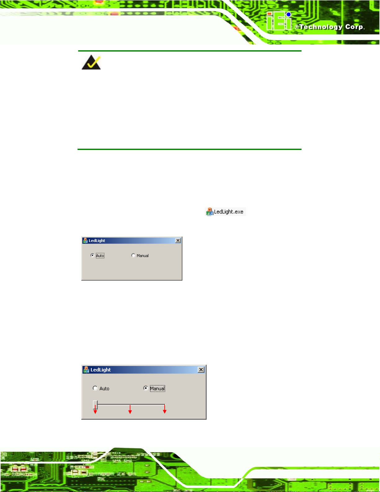
1.2.1.2 LE D Light
To configure the LED I ndicators light through a quick and easy way, please follow the
steps below:
Step 1: Double click the LED Light.exe icon
to open the LED Light
software.
Figure 1-4: LED Light Software (Auto)
Step 2: You can use the Auto option to adjust the LED Indicators light using preset
settings.
Step 3: Or you can use the Manual option to adjust the LED Indicators light using
following settings.
Figure 1-5: LED Light Software (Manual)
Darkest
Middle
Brightest
Page 28

AFL2-17A/AB-H61
Page 8
1.2.1.3 Function Keys
The corresponding Function Ke ys are located under the bottom right han d corner of the
LCD screen (Figure 1-6).
Figure 1-6: Function Keys
The Function Keys are described in Table 1-3:
Key Combination Function Key Description
Fn + LCD On/Off
RFID Enable/Disable
Fn + Audio Volume Down
Audio Mute
Fn + Audio Volume Up
Camera Enable/Disable
Fn + Brightness Down
Mini USB / Micro SD Enable/Disable
Fn + Brightness Up
Power On/Off
Note: To power on the system, hold down the Fn +
Brightness Up buttons for 3 seconds. To power down the
system, hold down the FN + Brightness Up buttons for six
seconds.
Fn: The function key can maintain for 2sec.
Table 1-3: Function Key Descriptions
Page 29
AFL2-17A/AB-H61
Page 9
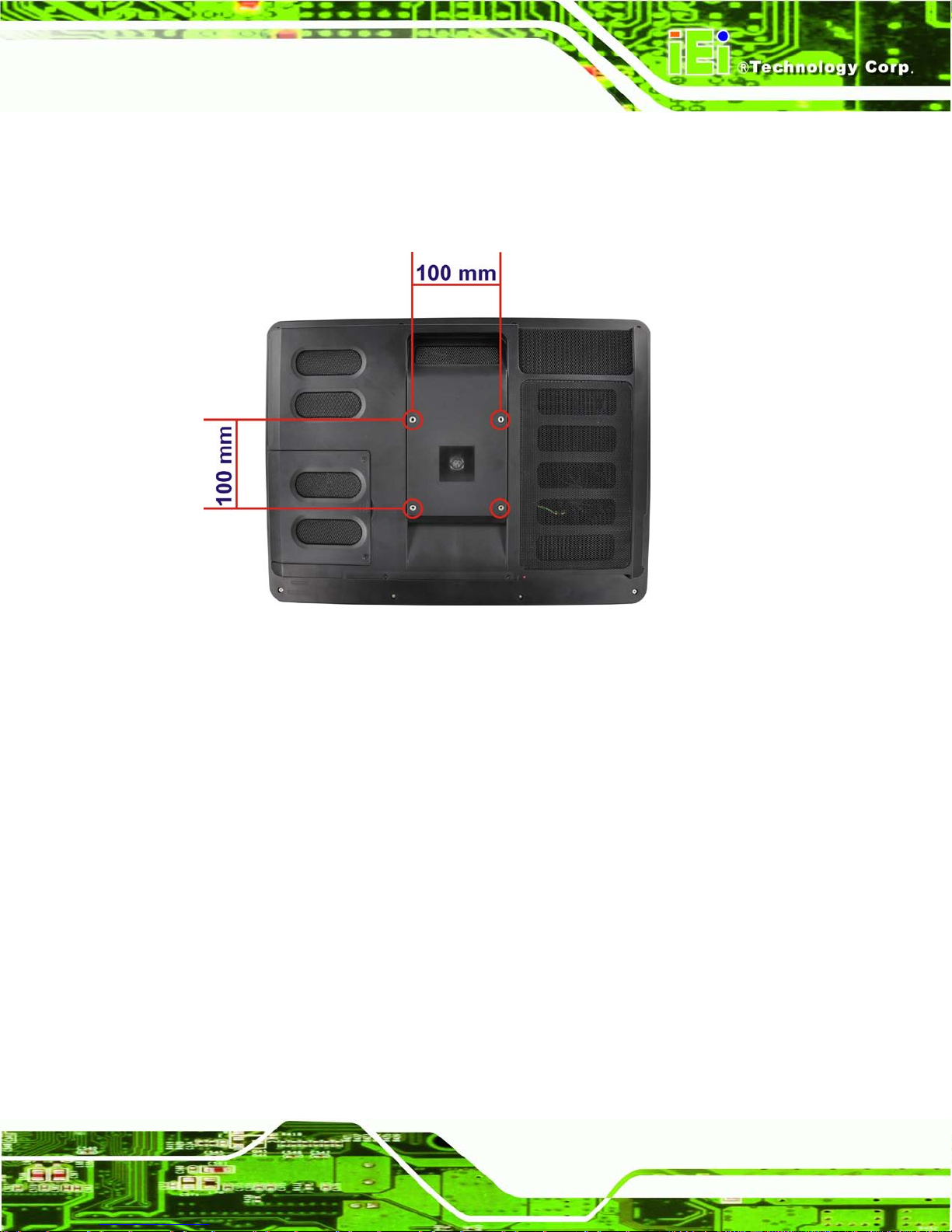
1.2.2 Rear Panel
The rear panel provides ac cess to retention screw holes that support various mounting.
Refer to Figure 1-7.
Figure 1-7: AFL2-17A/AB-H61 Rear View
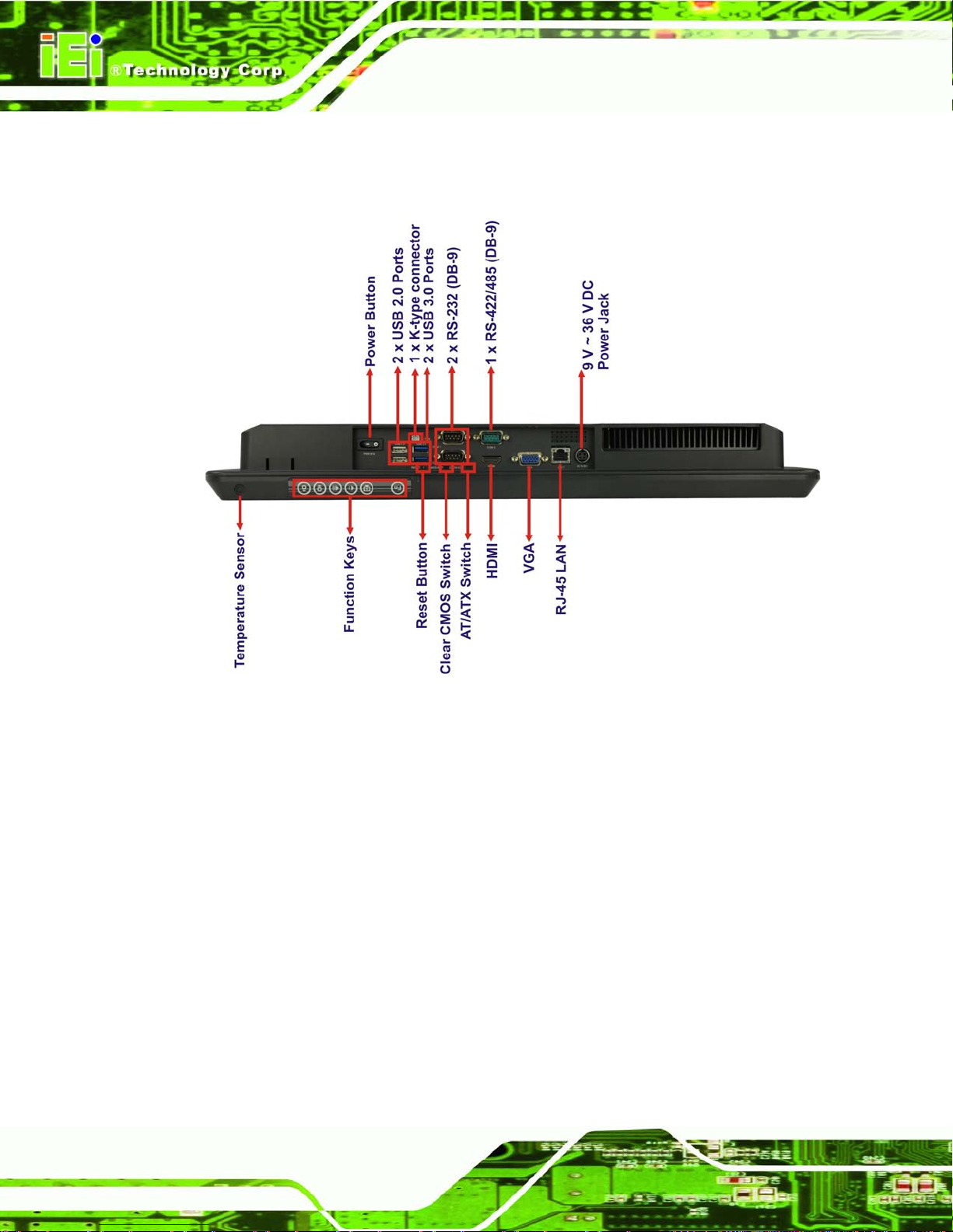
1.2.3 Bottom Panel
The bottom panel of the AFL2-17A/AB-H61 has the following features (Figure 1-8):
1 x AT/ATX Switch
1 x Clear CMOS switch
1 x 9V ~ 36V DC power jack
6 x Function keys
1 x HDMI port
1 x K-type connector
1 x Power button
1 x Reset button
1 x RJ-45 LAN connector
2 x RS-232 connectors (DB-9)
1 x RS-422/485 connector (DB-9)
1 x Temperature sensor
Page 30
AFL2-17A/AB-H61
Page 10
2 x USB 2.0 connectors
2 x USB 3.0 connectors
1 x VGA port
Figure 1-8: AFL2-17A/AB-H61 Bottom Panel
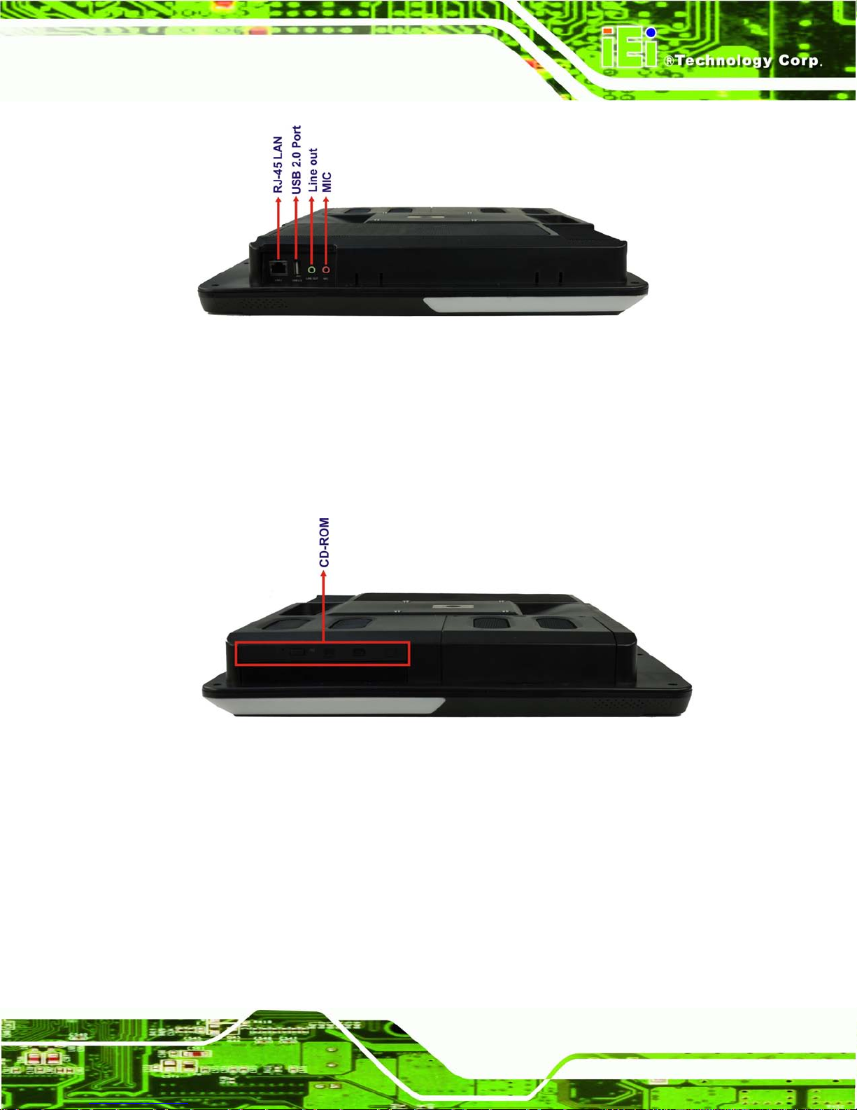
1.2.4 Left Side Panel
The left side panel of the AFL2-17A/AB-H61 has the following features (Figure 1-9):
2 x Audio jacks (Line out, MIC)
1 x RJ-45 LAN connector
1 x USB 2.0 connector
Page 31
AFL2-17A/AB-H61
Page 11
Figure 1-9: AFL2-17A/AB-H61 Left Side Panel
1.2.5 Right Side Panel
The right s ide panel of the AFL2-17A/AB-H61 pr ovides access to the CD-ROM (optional)
(Figure 1-10):
Figure 1-10: AFL2-17A/AB-H61 Right Side Panel
1.3 Int ernal Ov er v iew
The AFL2-17A/AB-H61 has the following components installed internally:
1 x Motherboard
2 x 2.0 GB 1333 MHz DDR3 SO-DIMMs
Page 32

AFL2-17A/AB-H61
Page 12
1.4 S ys tem Specifications
The technical specifications for the AFL2-17A/AB-H61 systems are listed in
Table 1-4.
Specification AFL2-17A/AB-H61
LCD Size 17" (4:3)
Max. Resolution 1280 (W) x 1024 (H)
Brightness (cd/m2) 350
Contrast Ratio 1000:1
LCD Color 16.7M
Pixel Pitch (H x V) (mm) 0.264(H) x 0.264 (V)
Viewing Angle (H-V) 170° / 170°
Backlight MTBF (hr) 50,000
Touch Screen 5-Wire resistive type touch screen (selected models only)
Projected capacitive type touch screen (selected models only)
CPU 2nd Generation Intel® Core™ i7/ i5/ i3, Pentium® and Celeron®
processor
Chipset Intel® H61
Ethernet Realtek RTL8111E PCIe GbE controller support ASF2.0
Memory Support two 204-pin DDR3 SO-DIMM slot (system max. 16GB)
preinstalled with 4GB (2GB x 2)
Expansion 1 x PCIe Mini slot for WiFi
1 x PCIe Mini slot reserved
HDD 2.5" SATA 2.0 HDD bay
CD-ROM 1 x Slim Type CD-ROM bay (optional)
Audio AMP 2 W + 2 W (built-in stereo speakers)
Camera 2 M pixels with low light function
Wireless 1 x Wireless LAN 802.11 b/g/n module
(internal PCIe Mini card interface)
1 x Bluetooth function
(optional internal USB interface, B lue tooth V2.1+EDR)
RFID Reader EM 125 KHz or MIFARE 13.56 MHz card reader (optional)
MSR card reader MSR card reader (optional)
TPM Reserved by pin-header
Page 33

AFL2-17A/AB-H61
Page 13
OSD Function LCD on / off, brightness up / down, volume up / down, Hot Key
Construction Material PC + ABS plastic front frame
Mounting Panel/Wall/Rack/Stand/Arm (V ESA 100 m m x 100 m m )
Front Panel Color Black
Weight (Net/Gross) 6.9 kg / 9.0 kg
Dimensions (W x H x D) (mm) 418 x 378 x 65
Operation Temperature -20ºC ~ 40ºC (Ambient with air flow)
Storage Temperature -20ºC ~ 60ºC
Humidity 10% to 95% (non-condensing)
IP level IP 64 compliant front panel
Power Supply 120W power adapter
Input: 100V AC ~ 240V AC @ 50 / 60 Hz
Output: 19V DC
Power Requirement 9V ~ 36V DC
I/O Ports and Switches 2 x RS-232 (DB-9 connector)
1 x RS-422/485 (DB-9 connector)
2 x GbE LAN (one on bottom side, one on left side)
2 x USB 3.0 connector
3 x USB 2.0 connectors (two on bottom side, one on left side)
1 x Mini USB 2.0 connector (on front panel)
1 x Micro SD card slot (o n front pane l)
1 x Line-out (on Left side)
1 x Mic (on Left side)
1 x VGA port (DB15 connector)
1 x HDMI port
1 x Power switch
1 x AT/ATX switch
1 x Reset button
1 x Clear CMOS button
1 x 9 V ~ 36V DC input jack
1 x k-type connector
Table 1-4: System Specifications
Page 34

AFL2-17A/AB-H61
Page 14
2 LED Light Bar (Optional)
Chapter
2
Page 35

AFL2-17A/AB-H61
Page 15
2.1 Overview
To notify field staffs in an efficient way to increase productivity, the AFL2-17A-H61
integrates LED dash light s ystem on the side fr ame. With the provided A PI software and
LED simulator software, us ers can customize their notification according to t heir needs
through a quick and eas y user interface. The customized functions inc lude light scripts,
programmable colors, light duration, flash rates and light patterns.
2.2 iEi LE D Light Bar Display Simulat or
To configure the LED light bars by iEi LED Lig ht Bar Display Sim ulator, please f ollow the
steps below:
Step 1: Make sure LED Bar driver is properly installed. See Sect ion 9.11.
Step 2: Double click the
icon to setup the iEi LED Light Bar
Display Simulator.
Step 3: The Setup Wizard starts (Figure 2-1).
Figure 2-1: The Setup Wizard Starts
Page 36
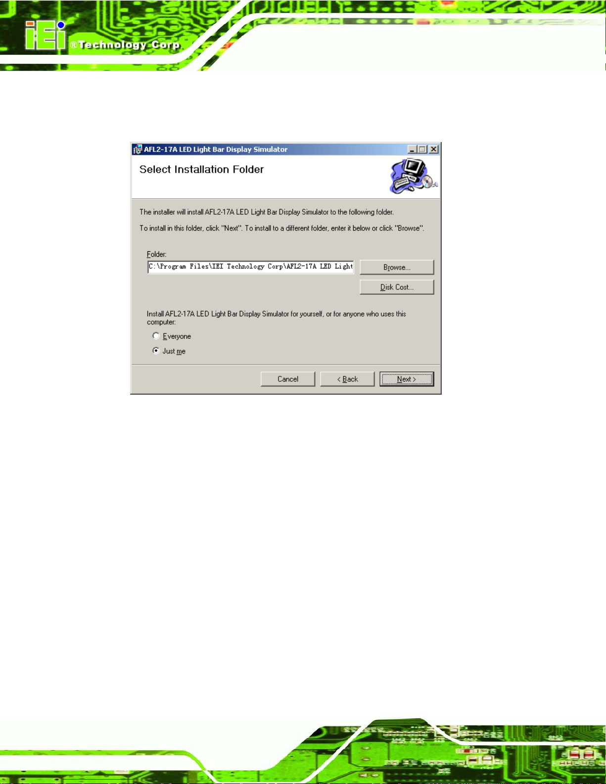
AFL2-17A/AB-H61
Page 16
Step 4: Click Next to continue.
Step 5: The Select Installation F o lder screen in Figure 2-2 appears.
Figure 2-2: Select Installation Folder Screen
Step 6: Click Next to continue.
Step 7: The Confirm Installation screen in Figure 2-3 appears.
Step 8: Click Next to proceed with the installation.
Page 37

AFL2-17A/AB-H61
Page 17
Figure 2-3: Confirm Installation Screen
Step 9: The program begins to install.
Step 10: When the installation is complete, the screen in Figure 2-4 appears.
Figure 2-4: Installation Complete
Page 38

AFL2-17A/AB-H61
Page 18
Step 11: Click Close to complete the installation.
Step 12: The iEi LED Light Bar Display Simulator icon
shows on the computer
desktop.
Step 13: Double click it to open the iEi LED Light Bar Display Simulator, as shown in
Figure 2-5.
Figure 2-5: iEi LED Light Bar Display Simulator
The descriptions of iEi LED Light Bar Display Simulator are listed below.
Function Des cription
New
Clear all current commands
Load
Load the configuration file ( *.cld )
Save
Save all current commands
Run
Start to simulate the LED display
Add
Add a new command
Page 39

AFL2-17A/AB-H61
Page 19
Function Des cription
Copy
Copy a command
Delete
Delete a command
UP
Move the command up
Down
Move the command down
Loop Start
Set loop start point.
Loop End
Set Loop end point
ALL
Select all the LED simulation buttons
TOP
Select the top LED simulation buttons
LEFT
Select the left LED simulation buttons
RIGHT
Select the right LED simulation buttons
1~30
LED simulation buttons
Table 2-1: LED Simulator Software Description
Step 14: Select the color. The color setting area includes basic color and user defined
color. Click the basic color to select the desired color.
Figure 2-6: Color Setting Area
Step 15: Or you can double click the user defined color to open the color palette and
select the desired color.
Basic Color
User Defined Color
Page 40

AFL2-17A/AB-H61
Page 20
Figure 2-7: Color Palette
Step 16: After setting the color, click LED simulation button and the color of selected LED
simulation button will automatically change. See Figure 2-8.
Figure 2-8: Simulate the LED Light
Step 17: If you want to set all the left LED simulation buttons for a certain color at the
same time, click the “LEFT" button. Setting the right LED simulation buttons and
top LED simulation buttons are the same way.
Page 41

AFL2-17A/AB-H61
Page 21
Figure 2-9: Set the Left LEDs
Step 18: If you want to set all the LED simulation buttons for a certain color at the same
time, click the “ALL" button.
Figure 2-10: Set All the LEDs
Page 42
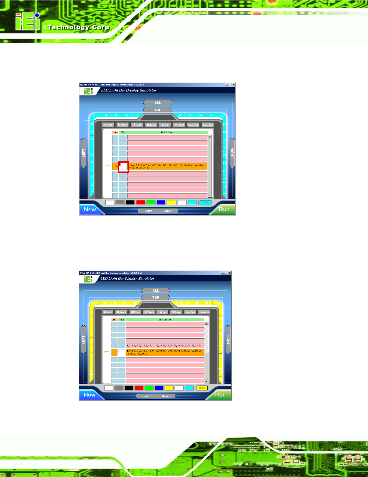
AFL2-17A/AB-H61
Page 22
Step 19: Enter the light duration. Please note that the unit is second, enter a number
between 1 and 20. See Figure 2-11.
Figure 2-11: Light Duration
Step 20: Press the Add button to insert a new control command. You may continue to set
a new command in accordance with Step14 ~ Step19.
Figure 2-12: Add new command
Page 43
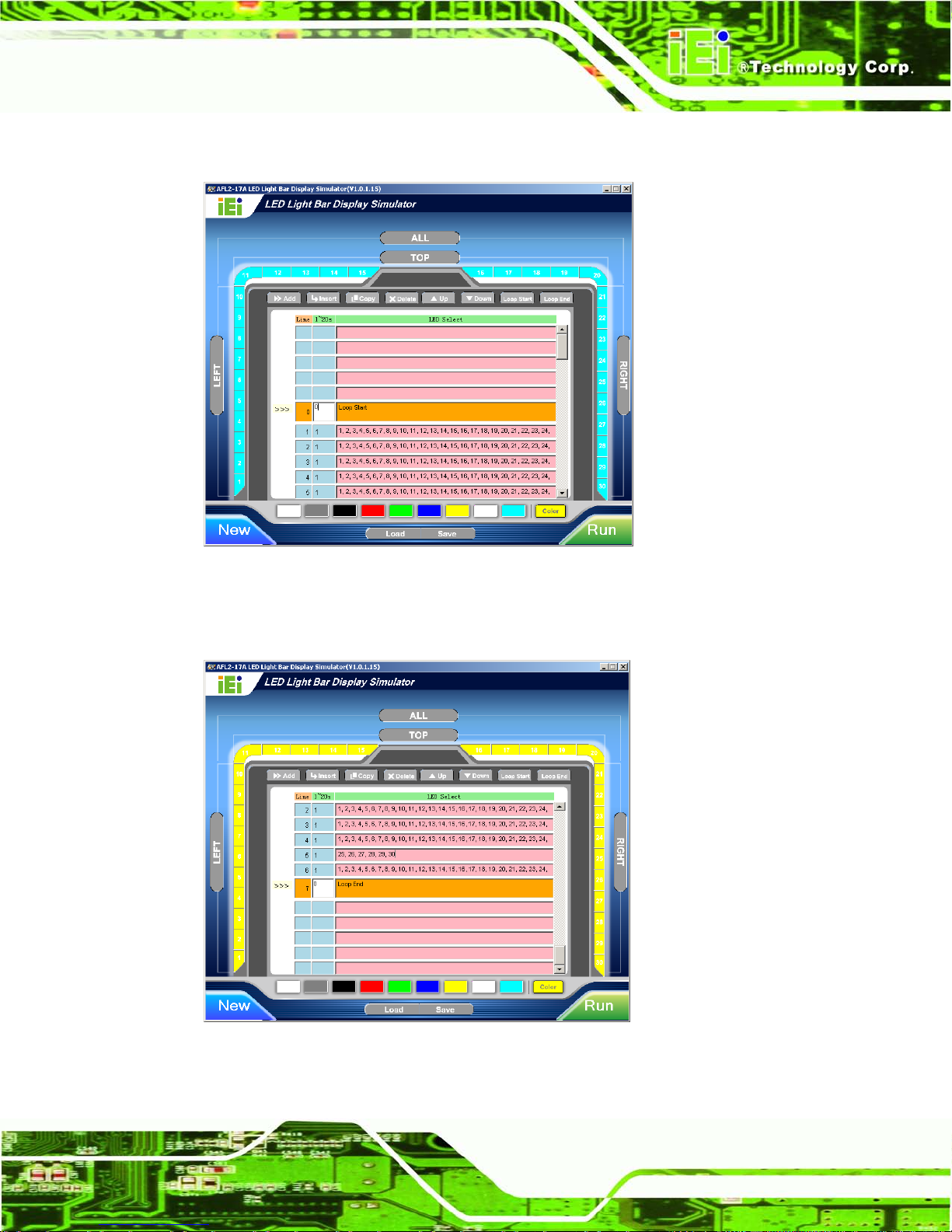
AFL2-17A/AB-H61
Page 23
Step 21: Press the Loop Start button to set loop start point.
Figure 2-13: Add Loop Start
Step 22: Press the Loop End button to set loop end point.
Figure 2-14: Add Loop End
Step 23: Press the Run button to simulate.
Page 44

AFL2-17A/AB-H61
Page 24
2.3 i E i LED Run
To configure the LED light bars t hrough a quick and easy way, please follow th e steps
below:
Step 1: Make sure the LED Bar driver is properly installed. See Section 9.11.
Step 2: Double click the LED-RUN.exe icon
to open the LED RUN
software, as shown in Figure 2-15.
Figure 2-15: iEi LED RUN Software
Step 3: The LED light bars start to dash in a preset mode.
2.4 LED Control API
2.4.1 Introduction
This chapter aims to explain how to use LED Light Bar Control API, and support API
version is V1.0.0.7. Due LED Light Bar driver only has x86 version, this API could be used
in the Windows 2000/XP(x86)/2003/7(x86) environments.
2.4.1.1 Programming Language Support
The iEi LED Light Bar Control application provides an interface to driver with:
Microsoft Visual C/C++
Microsoft Visual Basic
Other programming systems that can access functions into DLL's
2.4.1.2 Applica tion Content
The iEi LED Light Bar Control application includes the following files:
Page 45

AFL2-17A/AB-H61
Page 25
IBS_LEDCTRL.dll
IBS_LEDCTRL.lib
IBS_LEDCTRL.h
2.4.2 LED Control API Functions
2.4.2.1 LIGHTBAR_Drive rInit
Syntax: PACSM_LIGHTBAR_CTRL STD_HANDLE LIGHTBAR_DriverInit(void)
Parameters: NONE
Return value: Return a Handle from LED driver.
Remarks: Call this function to initial and start the LED Driver and retur n a Ha ndle fro m LED
driver.
2.4.2.2 LIGHTBAR_DriverUninit
Syntax: PACSM_LIGHTBAR_CTRL STD_Void LIGHTBAR_DriverUninit(HANDLE hDev)
Parameters: hDev [IN] – Handle be released.
Return value: True if success.
Remarks: Call this function to stop and uninitialized the LED Driver and to release resource of
Handle.
2.4.2.3 LIGHTBAR_De viceIn it
Syntax: PACSM_LIGHTBAR_CTRL STD_BOOLEN LIGHTBAR_DeviceInit(HANDLE hDev)
Parameters: hDev [IN] – Input Handle.
Return value: True if success.
Remarks: Call this function to initial the LED IC.
Page 46

AFL2-17A/AB-H61
Page 26
2.4.2.4 LIGHTBAR_DeviceClos e
Syntax: PACSM_LIGHTBAR_CTRL STD_BOOLEN LIGHTBAR_DeviceClose(HANDLE hDev)
Parameters: hDev [IN] – Input Handle.
Return value: True if success.
Remarks: Call this function to turn off LED IC.
2.4.2.5 LIGHTBAR_Brightness_Single
Syntax: PACSM_LIGHTBAR_CTRL STD_BOOLEN LIGHTBAR_Brightness_Single(
HANDLE hDev,
PLED_COLOR_INFO Brightness_Step,
int INFO_Size)
Parameters: hDev [IN] – Input Handle.
Brightness_Step [IN] –Point to structures buffer s to write. (see Section 2.4.3)
INFO_Size [IN] – describe the data structure array size.
Return value: True if success.
Remarks: Write data to LED IC on I2C bus via drivers. This function creates data structures
include the target LED IC address and Brightness information to send to LED IC via
LED Driver.
2.4.2.6 LIGHTBAR_BLNK_Settings
Syntax: PACSM_LIGHTBAR_CTRL STD_BOOLEN LIGHTBAR_BLNK_Settings(
HANDLE hDev,
PLED_BLNK_SET LED_Blinking_ Set)
Parameters: hDev [IN] – Input Handle.
LED_Blinking_Set [IN] –Point to structures buffers to write. (see Section 2.4.3)
Page 47

AFL2-17A/AB-H61
Page 27
Return value: True if success.
Remarks: This function is used to set LED IC Blinking modes via drivers.
2.4.2.7 LIGHTBAR_BLNK_Type
Syntax: PACSM_LIGHTBAR_CTRL STD_BOOLEN LIGHTBAR_BLNK_Type(
HANDLE hDev,
PLED_BLNK_TYPE Blinking_Type)
Parameters: hDev [IN] – Input Handle.
Brightness_Step [IN] –Point to structures buffers to write. (see Section 2.4.3)
Return value: True if success.
Remarks: This function is used to turn on/off LED IC blinking control via drivers.
2.4.2.8 LIGHTBAR_LED_ModeSet
Syntax: PACSM_LIGHTBAR_CTRL STD_BOOLEN LIGHTBAR_LED_ModeSet (
HANDLE hDev,
PLED_MODE_SETTINGS LED_Mode_Settings)
Parameters: hDev [IN] – Input Handle.
LED_Mode_Settings [IN] –Point to structures buffers to write. (see Section 2.4.3)
Return value: True if success.
Remarks: This function is used to set each LED operation mode on LED IC via drivers.
Page 48

AFL2-17A/AB-H61
Page 28
2.4.3 Structures
2.4.3.1 _LED_COLOR_INFO
Syntax: typedef struct _L E D_COLOR_I N FO {
LED_INFO LED_Info;
int R_LE V EL;
int G_LEV EL;
int B_LEV EL;
}LED_COLOR_INFO, *PLED_COLOR_INFO;
Parameters:
R_LEVEL、G_LEVEL、B_LEVEL [int] - Store the Brightness Level information for
R, G and B LED. The brightness level was from 0 to 7.
LED_Info [structure] - The LED IC address was stored in Main_Addr on the I2c
bus, and LED List number are stored in R_LN、G_LN and B_LN parameters:
typedef struct _LED_INFO {
UCHAR Main_Addr; //Main address
UCHAR R_LN; //Red list number
UCHAR G_LN; //Green list number
UCHAR B_LN; //B lue li s t numb e r
} LED_INFO, *PL ED_INFO ;
Remarks: This s tr uc ture has included essential information to set LED IC.
2.4.3.2 _LED_BLNK_SET
Syntax: typedef struct _LED_BLNK_SET{
UCHAR Main_Addr; //Main address
BYTE BLNK_DutCyc; //Duty Cycle
BYTE BLNK_Freq; //Blink ing Frequency
}LED_BLNK_SET, *PLED_BLNK_SET;
Parameters:
Main_Addr [UCHAR] - IC Address on I2C bus.
BLNK_DutCyc [BYTE] - Duty Cycle of LED blinking. Duty cycle = (0
~ 255)/256 = x%。
BLNK_Freq [BYTE] -Frequency of LED blinking. 0x00 = (41ms,
Page 49

AFL2-17A/AB-H61
Page 29
frequency 24H z),0xFF = (1 0.73s),Frequency = [(0~255) + 1]/24=
x(second),Ex:300ms = (7 + 1) / 24 ≒ 0.333s。
Remarks: This structure has used to store the blinking duty c ycle and freque ncy of LED IC.
Please attention one LED IC only has one duty cycle and frequency to be group
used, It means all LED has the same blink mode on a LED IC.
2.4.3.3 _LED_BLNK_SET
Syntax: typedef struct _LED_BLNK_TYPE{
UCHAR Main_Addr; //Main addr e ss
int BLNK_TYPE;
}LED_BLNK_TYPE, *PLED_BLNK_TYPE;
Parameters:
Main_Addr [UCHAR] – IC Address on I2C bus.
BLNK_Type [i nt] - T urn on/off blinking circuit on the LED IC. Defined
by:
#define LED_BLNK_ON 0
#define LED_BLNK_OFF 1
Remarks: This structure has used to turn on/off blinking cir c uit on the LED IC.
Page 50

AFL2-17A/AB-H61
Page 30
2.4.3.4 _LED_MODE_SETTINGS
Syntax: typedef stru c t _LED_MODE_ SETTING S {
UCHAR Main_Addr; //Main addr e ss
int LED_00;
int LED_01;
int LED_02;
int LED_03;
int LED_04;
int LED_05;
int LED_06;
int LED_07;
int LED_08;
int LED_09;
int LED_10;
int LED_11;
int LED_12;
int LED_13;
int LED_14;
}LED_MODE_SETTINGS, *PLED_M O DE_SETTINGS;
Parameters:
Main_Addr [UCHAR] – IC Add ress on I2C bus.
LED_00 ~ LED_15: Each LED operation mode, defined by:
#define LED_DispMode_OFF 0 //Turn OF F LED.
#define LED_DispMode_Gen 1 //General Mode
#define LED_DispMode_BLNK 2 //Blinking Mode
Remarks: This structure can decision operation mode for each LED.
2.4.4 Programming Example
2.4.4.1 Turn on LED - s ingle
{
//Define Data structure
PLED_PWM_INFO LEDCOLOR = (PLED_PWM_INFO)ma llo c (size o f(LED_PWM_INFO));
Page 51

AFL2-17A/AB-H61
Page 31
HANDLE hSMB_Dev = LIGHTBAR_DriverInit();//I nit S MB A PI dri v er and get dev ice Handle.
LIGHTBAR_DeviceInit(hSMB_ D e v);//Init Target device
//Set LED level information.
LEDCOLOR.R_LEVEL = 7;
LEDCOLOR.G _LEVEL = 7;
LEDCOLOR.B _LEVEL = 7;
//Set LED Address
LEDCOLOR.LED_Info.Main_A ddr = 0xC0 ;
LEDCOLOR.LE D_Info.R_L N = 0x00;
LEDCOLOR.LE D_Info.G_L N = 0x01;
LEDCOLOR.LED_Info.B_LN = 0x02;
If(LIGHTBAR_Brightness_Single(hSMB_Dev, LEDCOLOR, 1) == False){
//Error message
}
LIGHTBAR_DeviceClose(hSMB_Dev); //Close Device.
LIGHTBAR_DriverUninit(hSMB_Dev); //Close Driver Handle
delete LEDCOLOR;
}
2.4.4.2 Turn on LED - multiple
{
//Define Data structure
PLED_PWM_INFO LEDCOLOR = (PLED_PWM_INFO)ma llo c (size o f(LED_PWM_INFO) * 4);
HANDLE hSMB_Dev = LIGHTBAR_DriverInit();//I nit S MB A PI dri v er and get dev ice Handle.
LIGHTBAR_DeviceInit(hSMB_ D e v);//Init Target device
LEDCOLOR [0].LED_Info.Main_Addr = 0xD0;
LEDCOLOR [0].LED_Info.R_LN = 0x02;
LEDCOLOR [0].LED_Info.G_LN = 0x03;
LEDCOLOR [0].LED_Info.B_LN = 0x04;
LEDCOLOR [0].R_LEVEL = 7;
Page 52

AFL2-17A/AB-H61
Page 32
LEDCOLOR [0].G_LEVE L = 7;
LEDCOLOR [0].B_LEVE L = 7;
LEDCOLOR [1].LED_Info.Main_Addr = 0xD0;
LEDCOLOR [1].LED_Info.R_LN = 0x05;
LEDCOLOR [1].LED_Info.G_LN = 0x06;
LEDCOLOR [1].LED_Info.B_LN = 0x07;
LEDCOLOR [1].R_LEVEL = 7;
LEDCOLOR [1].G_LEVE L = 7;
LEDCOLOR [1].B_LEVE L = 7;
LEDCOLOR [2].LED_Info.Main_Addr = 0xD0;
LEDCOLOR [2].LED_Info.R_LN = 0x08;
LEDCOLOR [2].LED_Info.G_LN = 0x09;
LEDCOLOR [2].LED_Info.B_LN = 0x0a;
LEDCOLOR [2].R_LEVEL = 7;
LEDCOLOR [2].G_LEVE L = 7;
LEDCOLOR [2].B_LEVE L = 7;
LEDCOLOR [3].LED_Info.Main_Addr = 0xD0;
LEDCOLOR [3].LED_Info.R_LN = 0x0b;
LEDCOLOR [3].LED_Info.G_LN = 0x0c;
LEDCOLOR [3].LED_Info.B_LN = 0x0d;
LEDCOLOR [3].R_LEVEL = 7;
LEDCOLOR [3].G_LEVE L = 7;
LEDCOLOR [3].B_LEVE L = 7;
LEDCOLOR [4].LED_Info.Main_Addr = 0xD0;
LEDCOLOR [4].LED_Info.R_LN = 0x0e;
LEDCOLOR [4].LED_Info.G_LN = 0x0f;
LEDCOLOR [4].LED_Info.B_LN = 0x10;
LEDCOLOR [4].R_LEVEL = 7;
LEDCOLOR [4].G_LEVE L = 7;
LEDCOLOR [4].B_LEVE L = 7;
If(LIGHTBAR_Brightness_Single(hSMB_Dev, LEDCOLOR, 5) == False){
//Error message
}
Page 53

AFL2-17A/AB-H61
Page 33
LIGHTBAR_DeviceClose(hSMB_Dev); //Close Device.
LIGHTBAR_DriverUninit(hSMB_Dev); //Close Driver Handle
delete LEDCOLOR;
}
2.4.4.3 LE D Blink - 1
{
PLED_MODE_SETTINGS LED_ModeSet =
(PLED_MODE_SETTINGS)malloc(sizeof(LED_MODE_SETTINGS));
PLED_BLNK_SET LED_Blinking_Set = (P LED_BLNK_SET)malloc(sizeof(LED_BLNK_SET));
PLED_BLNK_TYPE LED_Blinking_Type =
(PLED_BLNK_TYPE)malloc(sizeof(LED_BLNK_TYPE));
// Set Structure: Set Broadcast address
LED_ModeSet.Main_Addr = 0xD0;
LED_Blinking_Set.Main_Addr = 0xD0;
LED_Blinking_Type.Main_Addr = 0xD0;
//Set Structure: Set blinking settings.
LED_Blinkin g_Set.BLNK _Freq = 0x07; //300ms
LED_Blinking_Set.BLNK_DutCyc = 0x80; //50:50
//Set Structure: Set each LED operation mode.
LED_ModeSet.LED_00 = LED_DispMode_BLNK; //R
LED_ModeSet.LED_01 = LED_DispMode_BLNK; //G
LED_ModeSet.LED_02 = LED_DispMode_BLNK; //B
LED_ModeSet.LED_03 = LED_DispMode_BLNK; //R
LED_ModeSet.LED_04 = LED_DispMode_BLNK; //G
LED_ModeSet.LED_05 = LED_DispMode_BLNK; //B
LED_ModeSet.LED_06 = LED_DispMode_BLNK; //R
LED_ModeSet.LED_07 = LED_DispMode_BLN K; //G
LED_ModeSet.LED_08 = LED_DispMode_BLNK; //B
LED_ModeSet.LED_09 = LED_DispMode_BLNK; //R
LED_ModeSet.LED_10 = LED_DispMode_BLNK; //G
LED_ModeSet.LED_11 = LED_DispMode_BLNK; //B
LED_ModeSet.LED_12 = LED_DispMode_BLNK; //R
LED_ModeSet.LED_13 = LED_DispMode_BLNK; //G
Page 54

AFL2-17A/AB-H61
Page 34
LED_ModeSet.LED_14 = LED_DispMode_BLNK; //B
LED_ModeSet.LED_15 = LED_DispMode_BLNK;
//Set Structure: Enable blinking of IC
LED_Blinking_Type.BLNK_TYPE = LED_BLNK_ON;
LIGHTBAR_BLNK_Settings (hSMB_ De v , LED_Bli nk ing_Set); //Set LED blinking
settings.
LIGHTBAR_LED_ModeSet(hSMB_Dev, LED_ModeSet) //Set LED Operation
Mode.
LIGHTBAR_BLNK_Type(hSMB_Dev, LED_Blinking_ Typ e ); //Enab le LE D B linking.
}
2.4.4.4 LE D Blink - 2
{
PLED_MODE_SETTINGS LED_Mode Set =
(PLED_MODE_SETTINGS)malloc(sizeof(LED_MODE_SETTINGS));
PLED_BLNK_SET LED_Blinking_Set = (P LED_BLNK_SET)malloc(sizeof(LED_BLNK_SET));
PLED_BLNK_TYPE LED_Blinking_Type =
(PLED_BLNK_TYPE)malloc(sizeof(LED_BLNK_TYPE));
// Set Structure: Set Broadcast address
LED_ModeSet.Main_Addr = 0xD0;
LED_Blinking_Set.Main_Addr = 0xD0;
LED_Blinking_Type.Main_Addr = 0xD0;
//Set Structure: Set blinking settings.
LED_Blinkin g_Set.BLNK _Freq = 0x07; //300ms
LED_Blinking_Set.BLNK_DutCyc = 0x80; //50:50
//Set Structure: Set each LED operation mode.
LED_ModeSet.LED_00 = LED_DispMode_Gen; //R
LED_ModeSet.LED_01 = LED_DispMode_Gen; //G
LED_ModeSet.LED_02 = LED_DispMode_Gen; //B
LED_ModeSet.LED_03 = LED_DispMode_BLNK; //R
LED_ModeSet.LED_04 = LED_DispMode_BLNK; //G
LED_ModeSet.LED_05 = LED_DispMode_BLNK; //B
Page 55

AFL2-17A/AB-H61
Page 35
LED_ModeSet.LED_06 = LED_DispMode_Gen; //R
LED_ModeSet.LED_07 = LED_DispMode_Gen; //G
LED_ModeSet.LED_08 = LED_DispMode_Gen; //B
LED_ModeSet.LED_09 = LED_DispMode_BLNK; //R
LED_ModeSet.LED_10 = LED_DispMode_BLNK; //G
LED_ModeSet.LED_11 = LED_DispMode_BLNK; //B
LED_ModeSet.LED_12 = LED_DispMode_Gen; //R
LED_ModeSet.LED_13 = LED_DispMode_Gen; //G
LED_ModeSet.LED_14 = LED_DispMode_Gen; //B
LED_ModeSet.LED_15 = LED_DispMode_BLNK;
//Set Structure: Enable blinking of IC
LED_Blinking_Type.BLNK_TYPE = LED_BLNK_ON;
LIGHTBAR_BLNK_Settings (hSMB_ De v , LED_Bli nk ing_Set); //Set LED blinking
settings.
LIGHTBAR_LED_ModeSet(hSMB_Dev, LED_ModeSet) //Set LED Operation
Mode.
LIGHTBAR_BLNK_Type(hSMB_Dev, LED_Blinking_Typ e ); //Enab l e LED B linking.
}
NOTE:
. The LED addresses are s ho wn belo w.
Page 56

AFL2-17A/AB-H61
Page 36
C8
C6
C4
ADDRESS
CA
DC
DE
LED_B_ListNumber = 04
LED_G_ListNumber = 03
LED_R_ListNumber = 02
LED_B_ListNumber = 0A
LED_G_ListNumber = 09
LED_R_ListNumber = 08
LED_B_ListNumber = 0D
LED_G_ListNumber = 0C
LED_R_ListNumber = 0B
LED_B_ListNumber = 10
LED_G_ListNumber = 0F
LED_R_ListNumber = 0E
LED_B_ListNumber = 07
LED_G_ListNumber = 06
LED_R_ListNumber = 05
LED_R_ListNumber = 0E
LED_G_ListNumber = 0F
LED_B_ListNumber = 10
LED_R_ListNumber = 08
LED_G_ListNumber = 09
LED_B_ListNumber = 0A
LED_R_ListNumber = 05
LED_G_ListNumber = 06
LED_B_ListNumber = 07
LED_R_ListNumber = 02
LED_G_ListNumber = 03
LED_B_ListNumber = 04
LED_R_ListNumber = 0B
LED_G_ListNumber = 0C
LED_B_ListNumber = 0D
LED_R_ListNumber = 02
LED_G_ListNumber = 03
LED_B_ListNumber = 04
LED_R_ListNumber = 05
LED_G_ListNumber = 06
LED_B_ListNumber = 07
LED_R_ListNumber = 08
LED_G_ListNumber = 09
LED_B_ListNumber = 0A
LED_R_ListNumber = 0B
LED_G_ListNumber = 0C
LED_B_ListNumber = 0D
LED_R_ListNumber = 0E
LED_G_ListNumber = 0F
LED_B_ListNumber = 10
LED_R_ListNumber = 0E
LED_G_ListNumber = 0F
LED_B_ListNumber = 10
LED_R_ListNumber = 08
LED_G_ListNumber = 09
LED_B_ListNumber = 0A
LED_R_ListNumber = 05
LED_G_ListNumber = 06
LED_B_ListNumber = 07
LED_R_ListNumber = 02
LED_G_ListNumber = 03
LED_B_ListNumber = 04
LED_R_ListNumber = 0B
LED_G_ListNumber = 0C
LED_B_ListNumber = 0D
Page 57

AFL2-17A/AB-H61
Page 37
3 Detailed Specifications
Chapter
3
Page 58
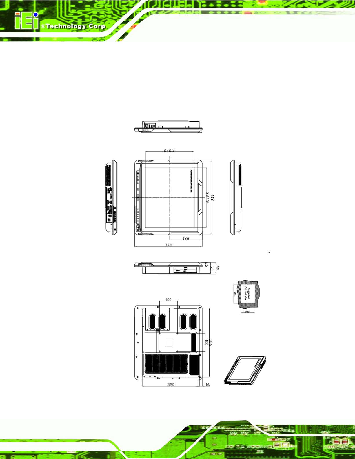
AFL2-17A/AB-H61
Page 38
3.1 Dimensions
The AFL2-17A/AB-H61 dimensions are shown below.
Width: 418.0 mm
Height: 378.0 mm
Depth: 65.0 mm
Figure 3-1: AFL2-17A/AB-H61 Dimensions (mm)
Page 59

AFL2-17A/AB-H61
Page 39
3.2 In te l® Core™ Desktop Processor
An Intel® 2nd generation Core™ desktop processor is ins ta lle d in t h e s yst em. The Sandy
Bridge CPU interfaces with the H61 chipset through a Direct Media Interf ace (DM I) and a
Flexible Display Interface (FDI).
3.3 Motherboard Components
The following sections describe some of the features on the motherboard.
3.3.1 Me mory Capacity
Two 204-pin 1066/1333 MHz dual-channe l DDR3 SDR AM SO-DIMMs supported (system
max. 16GB) in the AFL2-17A/AB-H61 and controlled by the Intel® Core™ desktop
processor installed on the internal motherboard.
3.3.2 Storage Capacity
The AFL2-17A/AB-H61 comes equipped with a 2.5” SATA 2.0 HDD drive ba y which can
be easily accessed by removing two screws on the HDD cover.
3.4 External Peripheral Interface Connectors
The following section describes the external peripheral interface connectors on the bottom
panel and left side panel of the system.
3.4.1 Se rial Port Connectors
The AFL2-17A/AB-H61 has three serial ports. COM1 and COM2 support only RS-232
serial communications . The other ser ial port (COM 3) can be conf igured as an RS-422 or
RS-485 serial port. Enabling COM devices to be powered through the COM port
eliminates unnecessary and messy cabling.
Page 60
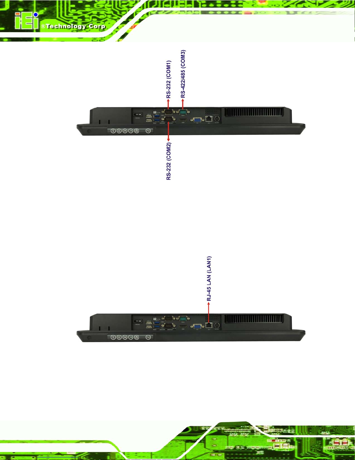
AFL2-17A/AB-H61
Page 40
Figure 3-2: Serial Ports
3.4.2 LAN Connectivity
The AFL2-17A/AB-H61 has one RJ-45 LAN connector on the bottom panel and one RJ-45
LAN connector on the left side panel.
Figure 3-3: RJ-45 Ethernet Connector (Bottom Panel)
Page 61
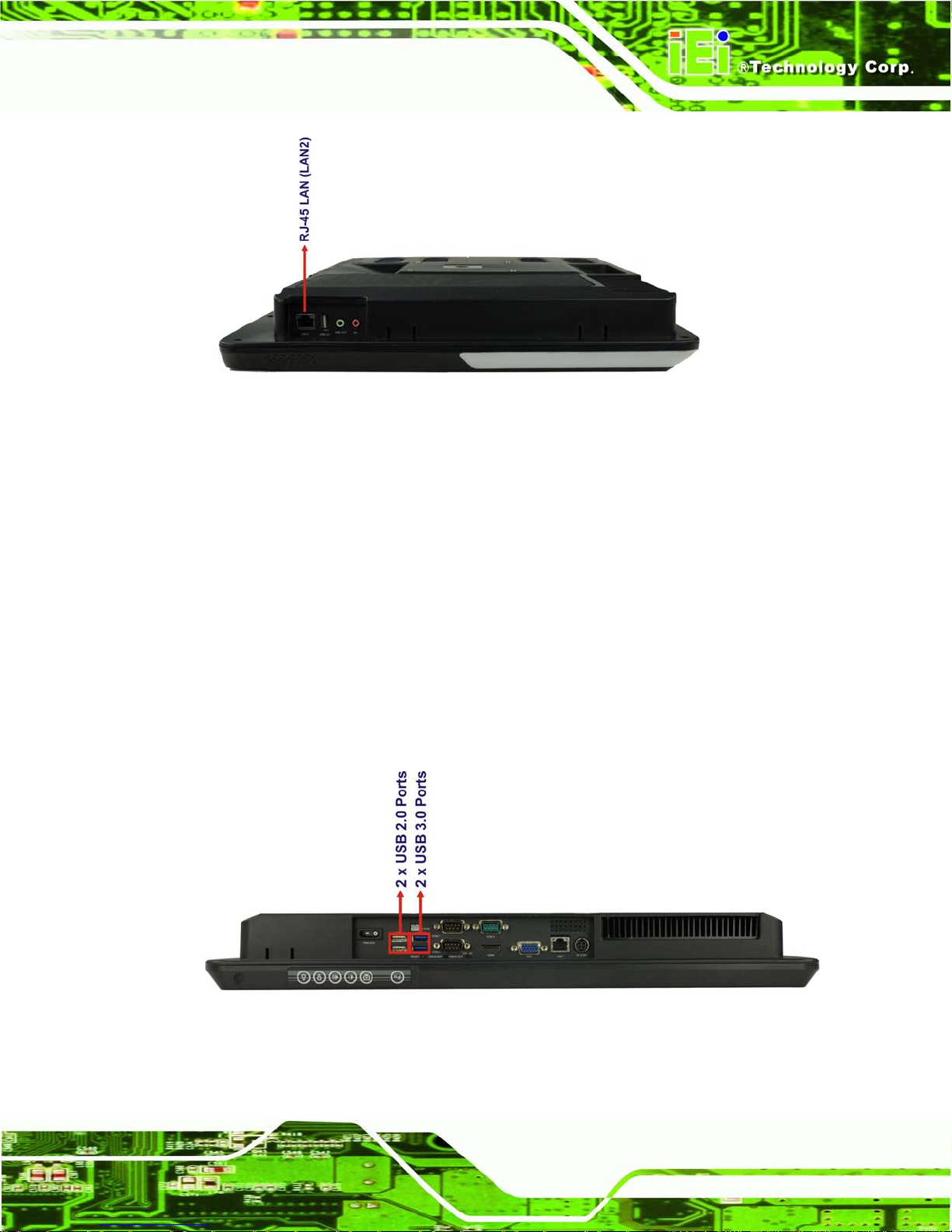
AFL2-17A/AB-H61
Page 41
Figure 3-4: RJ-45 Ethernet Connector (Left Side Panel)
The PCIe LAN from the Intel® H61 chipset of the AFL2-17A/AB-H61 is interfac ed to the
Realtek RTL8111E PCIe gigabit Ethernet (GbE) controllers. The RTL8111E controllers
are connected directly to the RJ-45 connectors and provide external GbE connectivity.
3.4.3 External USB Connectors
There are two USB 2.0 connectors and two US B 3.0 c onnect ors on the bo ttom panel and
one USB 2.0 connector on the left side panel of the AFL2-17A/AB-H61. All USB
connectors are full y compli ant with US B specif ication R evision 2. 0 and USB specif ication
Revision 1.1 and can be in t erf ac ed to both USB 1.1 and USB 2.0 com pliant de vices. Only
USB 3.0 connectors are compatible with USB 3.0 devices.
Figure 3-5: External USB Ports (Bottom Panel)
Page 62
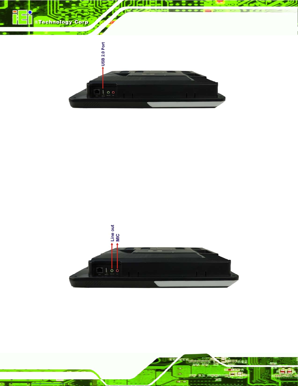
AFL2-17A/AB-H61
Page 42
Figure 3-6: External USB Ports (Left Side Panel)
3.5 Audio
3.5.1 Audio Codec Controller
The integrated HD Audio compliant audio controller on the Intel® H61 PCH is integrated to
a Realtek ALC892 audio codec. T he Realtek ALC892 is connected to two external aud io
jacks (Line out, MIC), wh ich are the n connec ted to c om pliant audio devices. The Realtek
ALC892 is a 7.1+2 channel high definition audio codec with ten DAC channels. It supports
7.1 sound playbac k and 2 channels of indep endent st ereo so und output . The a udio jacks
are shown in Figure 3-7.
Figure 3-7: Audio Jack
3.5.2 Stereo Speakers
Two internal 2 W stereo speakers on the sides of the AFL2-17A/AB-H61 are interfaced to
the system.
Page 63
AFL2-17A/AB-H61
Page 43
4 Unpacking
Chapter
4
Page 64

AFL2-17A/AB-H61
Page 44
4.1 Unpacking
To unpack the flat bezel panel PC, follow the steps below:
WARNING!
The front side LCD screen has a protective plastic cover stuck to the
screen. Only remove the plastic cover after the flat bezel panel PC has
been properly installed. This ensures the screen is protected during the
installation process.
Step 1: Use box cutters, a knife or a sharp pair of scissors that seals the top side of the
external (second) box.
Step 2: Open the external (second) box.
Step 3: Use box cutters, a knife or a sharp pair of scissors that seals the top side of the
internal (first) box.
Step 4: Lift the monitor out of the boxes.
Step 5: Remove both polystyrene ends, one from each side.
Step 6: Pull the plastic cover off the flat bezel panel PC.
Step 7: Make sure all the components listed in the packing list are present. Ste p 0:
4.1.1 Pack ing Lis t
The AFL2-17A/AB-H61 flat bezel panel PC is shipped with the following components:
Quantity Ite m Image
Standard
1 AFL2-17A/AB-H61 panel PC
Page 65

AFL2-17A/AB-H61
Page 45
1 Power adapter
(P/N: 63000-FSP120AAB-RS)
1 Power cord
(P/N: 32702-000401-100-RS)
1 Power transfer cord
(P/N: 32000-089400-RS)
1 Infrared remote controller
(P/N: 7Z000-SLPCB005-RS)
1 IO bracket
(P/N: 41013-0290C2-00-RS)
1 Temperature sensor cable
(P/N: 32133-004300-100-RS)
1 Pen
(P/N: 43125-0002C0-00-RS)
4 M3 screw pack
(P/N: 44013-030041-RS)
4 M4 screw pack
(P/N: 44033-040061-RS)
1 Utility CD
1 One Key Recovery C D
Optional
Page 66

AFL2-17A/AB-H61
Page 46
Panel Mounting Kit
(P/N: AFL2PK-17A)
Wall mounting kit
(P/N: AFLWK-19/AFLWK-19B)
Rack Mounting Kit
(P/N: AFL2RK-17A)
Arm
(P/N: ARM-31-RS)
Stand
(P/N:STAND-A19/STAND-B19/STAND-C19/
STAND-210-R11/STAND-A26-R11)
Hybrid Card Reader
(P/N: AFL2P-12AMSI-U-R10)
Magnetic Stripe Reader
(P/N: AFL2P-12AMSR-U-R10)
Slim DVD Burner
(P/N: 73400-AD7700S01-RS)
Bluetooth Module Kit
(P/N: AFL2-BT-KIT01-R11)
Page 67

AFL2-17A/AB-H61
Page 47
Trusted Platform Module (TPM)
(P/N: TPM-IN01-R11)
OS: Win CE 6.0 (DVD-ROM)
(P/N: AFL2-17A-H61-CE060-R10)
OS: Win XPE (DVD-ROM)
(P/N: AFL2-17A-H61-XPE-R10)
OS: Linux (DVD-ROM)
(P/N: AFL2-17A-H61-LNX-R10)
OS: Win 7 Embedded (DVD-ROM)
(P/N: AFL2-17A-H61-WES7P-R10
AFL2-17A-H61-WES7E-R10)
If any of these items are missing or damaged, contact the distributor or sales
representative imm ediately.
Page 68

AFL2-17A/AB-H61
Page 48
5 Installation
Chapter
5
Page 69

AFL2-17A/AB-H61
Page 49
5.1 Anti-static Precautions
WARNING:
Failure to take ESD precautions during the maintenance of the
AFL2-17A/AB-H61
may result in permanent damage to the
AFL2-17A/AB-H61 and severe injury to the user.
Electrostatic discharge (ESD) can cause serious damage to electronic components,
including the AFL2-17A/AB-H61. Dry climates are especially susceptible to ESD. It is
therefore critical that whenever the AFL2-17A/AB-H61 is acces sed int er na lly, or any other
electrical com ponent is handled, t he following anti-s tatic precautions are s trictly adhered
to.
Wear an anti-static wristband: - Wearing a simple anti-static wristband can
help to prevent ESD from damaging the board.
Self-grounding: - Before handling the board touch any grounded conducting
material. During the time the board is handled, frequently touch any
conducting materials that are connected to the ground.
Use an anti-static pad: - When configuring the AFL2-17A/AB-H61, place it
on an antic-static pad. This reduces the possibility of ESD damaging the
AFL2-17A/AB-H61.
Only handle the edges of the PCB: - When handling the PCB, hold the PCB
by the edges.
5.2 Installation Precautions
When installing the flat bezel pane l PC, please follow the precautions listed below:
Power turned off: When installing the flat bezel panel PC, make sure the
power is off. Failing to turn off the power may cause severe injury to the body
and/or damage to the system.
Certified Engineers: Only certified engineers should install and modify
onboard functionalities.
Page 70

AFL2-17A/AB-H61
Page 50
Anti-static Discharge: If a user open the rear panel of the flat bezel panel PC,
to configure the jumpers or plug in added peripheral devices, ground
themselves first and wear and anti-static wristband.
5.3 Ins tallation and Configuration Ste ps
The following installation steps must be followed.
Step 1: Unpack the flat bezel panel PC.
Step 2: Install the HDD.
Step 3: Install the K-type temperature sensor .
Step 4: Install the RFID reader (optional).
Step 5: Install the CD-ROM (optional).
Step 6: Configure the system.
Step 7: Connect peripheral devices to the flat bezel panel PC.
Step 8: Mount the flat bezel panel PC. Ste p 0:
5.4 HDD Ins tallation
WARNING:
Over-tightening back
cover screws will crack the plastic frame.
Maximum torque for cover screws is 5 kg-cm (0.36 lb-ft/0.49 Nm).
To install the HDD into the AFL2-17A/AB-H61, please follow the steps below:
Step 1: Remove two (2) retention screws from the HDD cover (Figure 5-1).
Page 71

AFL2-17A/AB-H61
Page 51
Figure 5-1: HDD Cover Retention Screws
Step 2: Remove the HDD cover from the device.
Step 3: Loosen the captive screw to release the HDD bracket from the chassis (Figure
5-2).
Figure 5-2: HDD Bracket Screw
Page 72

AFL2-17A/AB-H61
Page 52
Step 4: Slide the HDD bracket out of the device as shown (Figure 5-3).
Figure 5-3: Removing the HDD Bracket
Step 5: Insert an HDD into the bracket as shown (Figure 5-4).
Figure 5-4: Inserting the HDD
Page 73

AFL2-17A/AB-H61
Page 53
Step 6: Secure the HDD to the bracket using four (4) retention screws (two screws on
each side) (Figure 5-5).
Figure 5-5: Securing the HDD
Step 7: Slide the HDD module back into the device.
Step 8: Tighten the captive screw.
Step 9: Replace the HDD cover and secure it using two (2) retention screws. Step 0:
5.5 K-Typ e Temperature Sensor Ins tallation
The AFL2-17A/AB-H61 has a K-type connector on the external peripheral interface panel.
The K-type connector is connected to a K-type temperature sensor cable. The K-type
temperature sensor cable can be found in the packing list. To connect a K-type
temperature sensor cable to the AFL2-17A/AB-H61, please follow the instructions below.
Step 1: Locate the K-type connector. The location is shown in Chapter 1.
Step 2: Align the connector. Align the K-type temperature sensor cable with the K-type
connector on the AFL2-17A/AB-H61 . Make sure the orientation of the connector
is correct.
Page 74
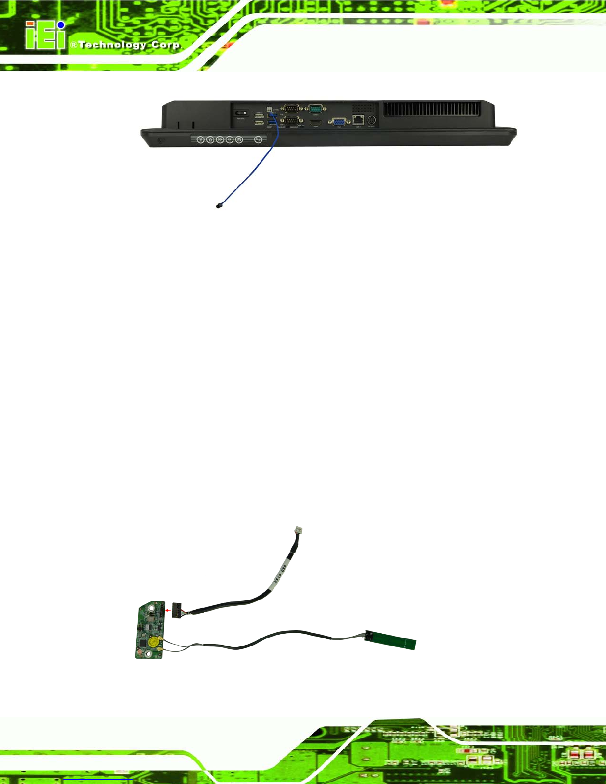
AFL2-17A/AB-H61
Page 54
Figure 5-6: Insert the K-type Temperature Sensor Cable
Step 3: Insert the K-type connector. Gently insert the K-type temperature sensor cable.
The connector should engage with a gentle push.
5.6 RFID Re ad er (Optional)
The AFL2-17A/AB-H61 series (selected models only) s uppor ts RFID reader functi on. T he
RFID reader is locat ed at the bottom of the screen. An optiona l Mifare 13. 56 MHz or EM
125 KHz RFID reader can be integrated in the system. All the data on the RFID tag can be
easily retrieved or upda ted through the reader to secure the data tr ansmission process
and increase efficienc y for certain ident it y group.
To install the RFID reader, follow the steps below.
Step 1: Connect the RFID USB cable to the USB connector on the RFID reader module.
(Figure 5-7)
Figure 5-7: Connect the RFID USB cable
Page 75
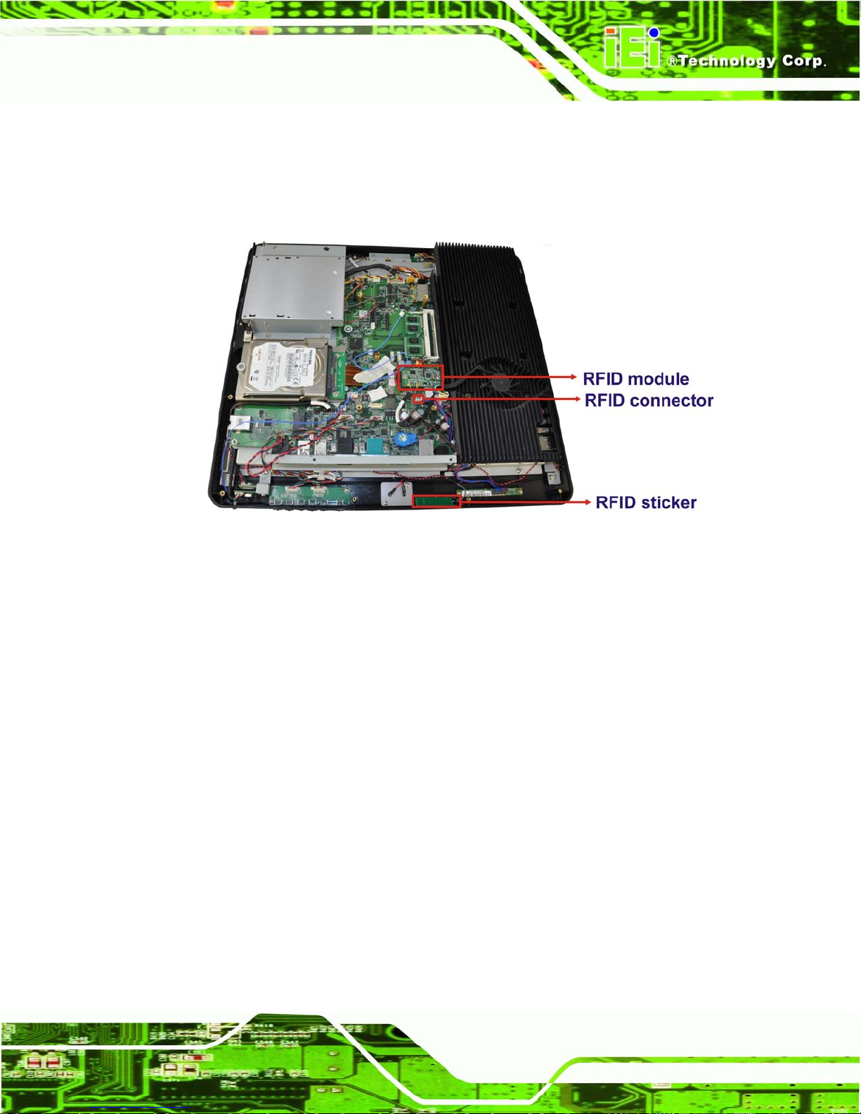
AFL2-17A/AB-H61
Page 55
Step 2: Connect the RFID connector of the RFID USB cable to the RFID connector on
the motherboard (RFID_USB1).
Step 3: Attach the sticker of the RFID module to the bottom of the panel.
Figure 5-8: Install the RFID module
Step 4: Secure the RFID module to the motherboard using two retention screws on
either side.
Step 5: Use the RFID reader to read a RFID card.
5.7 DVD-ROM Ins tallation (Optional)
To install a DVD-ROM, please follow the steps below.
Step 1: Remove four screws from the DVD-ROM cover (Figure 5-9).
Page 76

AFL2-17A/AB-H61
Page 56
Figure 5-9: DVD-ROM Cover
Step 2: Remove the DVD-ROM cover.
Step 3: Insert the DVD-ROM to the DVD-ROM bay. Attach the SATA cable to the
DVD-ROM and fasten the SATA cable screws (Figure 5-10).
Figure 5-10: Install the DVD-ROM
Page 77
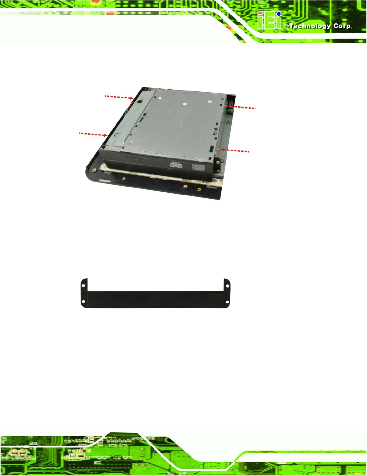
AFL2-17A/AB-H61
Page 57
Step 4: Secure the DVD-ROM to the DVD-ROM bracket using four screws (two screws
on each side) (Figure 5-11).
Figure 5-11: DVD-ROM Bracket Screws
Step 5: Install the new DVD-ROM cover and fasten four screws on the DVD-ROM cover.
The new DVD-ROM cover can be found in the packing list and is shown in
Figure 5-12.
Figure 5-12: DVD-ROM Cover
5.8 AT/ATX Mode Se lection
AT or AT X power mode can be us ed on the AFL2-17A/AB-H61. The selection is made
through an AT/ATX s witch l ocated on the bottom panel (Figure 5-13). To select AT mode
or ATX mode, follow the steps below.
Step 1: Locate the AT/ATX switch on the bottom panel (Figure 5-13).
Page 78
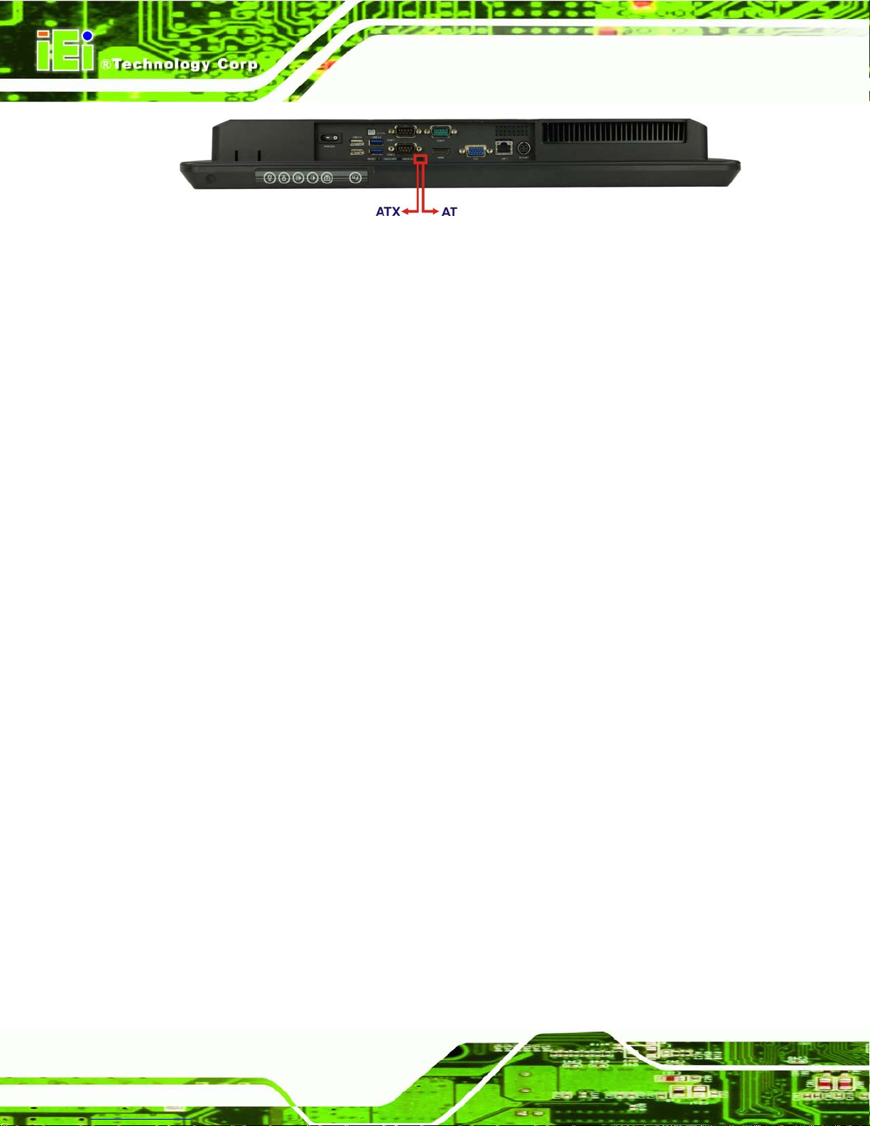
AFL2-17A/AB-H61
Page 58
Figure 5-13: AT/ATX Switch Locatio n
Step 2: Adjust the A T/A TX switch. Step 0:
5.8.1 AT Power Mode
With the AT mode selec ted, the po wer is control led by a centra l power un it rather than a
power switch. The AFL2-17A/AB-H61 pa nel PC turns o n automatically when the power is
connected. The AT mode benefits a production lin e to control multi ple panel PCs from a
central management center and other applications including:
ATM
Self-service kiosk
Plant environment monitoring system
Factory automation platform
Manufacturing shop flow
5.8.2 ATX Power Mode
With the ATX mode select ed, the AFL2-17A/AB-H61 panel PC goes in a standby mode
when it is turned of f . T he pane l PC c a n b e eas i ly tur n ed on v ia net wor k or a power switch
in standby mode. Remote power control is perfect f or advertising applications since the
broadcasting time for each panel PC can be set individually and controlled remotely. Other
possible application includes
Security surveillance
Point-of-Sale (POS)
Advertising terminal
5.9 Clear CMOS
If the AFL2-17A/AB-H61 fails to boot due to improper BIOS settings, the clear CMOS
switch clears the CMOS da ta and resets the s ystem BIOS infor mation. To do this , adjust
Page 79
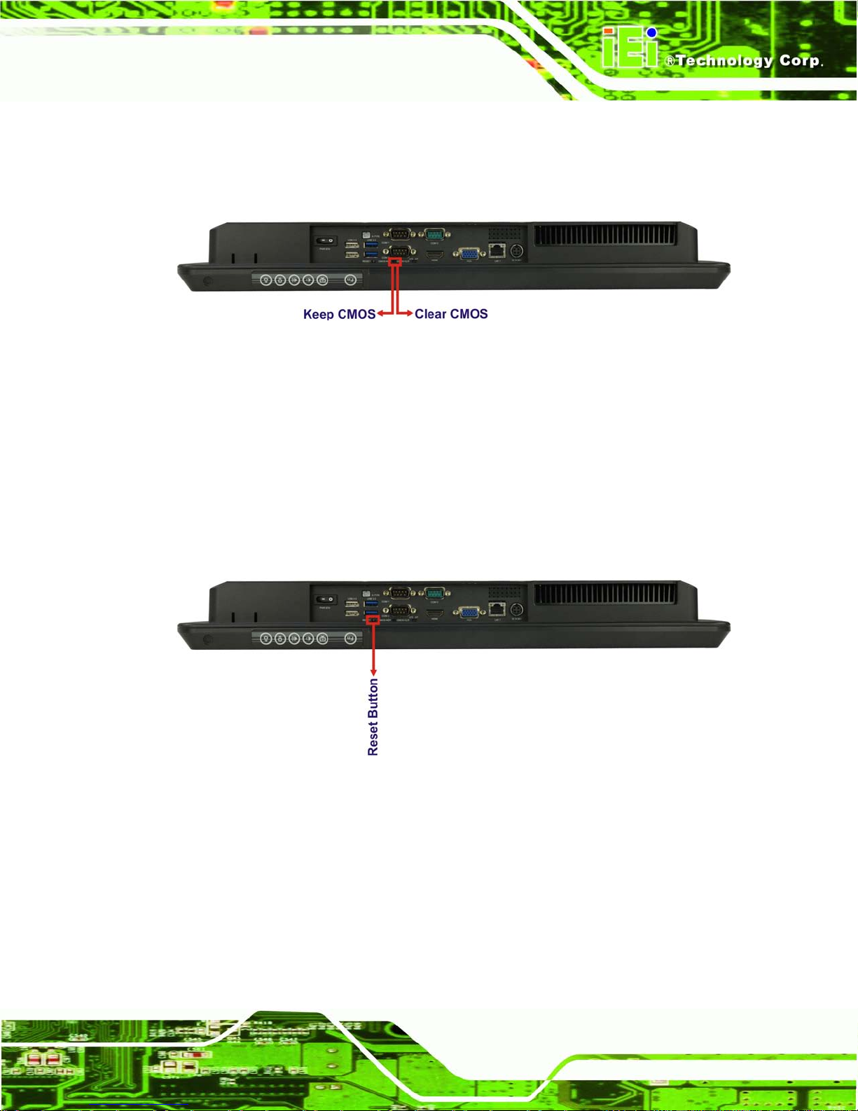
AFL2-17A/AB-H61
Page 59
the clear CMOS switch to clear CMOS m ode for a few seconds then r einstall the clear
CMOS switch back to keep CMOS mode.
Step 1: Locate the clear CMOS switch on the bottom panel (Figure 5-14).
Figure 5-14: Clear CMOS Switch Location
Step 2: Adjust the clear CMOS switch. Ste p 0:
5.10 Res et the System
The reset button en ables user to reboot the s ystem when the system is turned on. To
reboot the system, follow the steps below.
Step 1: Locate the reset button on the bottom panel (Figure 5-15).
Figure 5-15: Reset Button Location
Step 2: Press the reset button. Step 0:
5.11 Powering On th e System
To power on the system, follow the steps below:
Step 1: Locate the Function and Brightness Up function keys. See Section 1.2.1.1.
Page 80

AFL2-17A/AB-H61
Page 60
Step 2: Hold down the Function and Brightness Up buttons for three seconds to power
on the system. Step 0:
5.12 Po w ering Off the Syste m
To power off the system, follow the steps below:
Step 1: Locate the Function and Brightness Up function keys. See Section 1.2.1.1.
Step 2: Hold down the Function and Brightness Up buttons for six seconds to power off
the system. Ste p 0:
5.13 Mounting the Sys tem
WARNING!
When mounting the flat bezel panel PC onto an arm, onto the wall or onto a
panel, it is better to h av e m ore tha n o ne person to help with the i nstal lat ion
to make sure the pane l PC does not fall down and get damaged.
The four methods of mounting the AFL2-17A/AB-H61 are listed below.
Wall mounting
Panel mounting
Stand mounting
Arm mounting
The four mounting methods are described below.
5.13.1 Wall Mounting
To mount the flat bezel panel PC onto the wall, please follow the steps below.
Step 1: Select the location on the wall for the wall-mounting bracket.
Step 2: Carefully mark the locations of the four screw holes in the bracket on the wall.
Page 81

AFL2-17A/AB-H61
Page 61
Step 3: Drill four pilot holes at the marked locations on the wall for the bracket retention
screws.
Step 4: Align the wall-mounting bracket screw holes with the pilot holes.
Step 5: Secure the mounting-bracket to the wall by inserting the retention screws into
the four pilot holes and tightening them (Figure 5-16).
Figure 5-16: Wall-mounting Bracket
Page 82

AFL2-17A/AB-H61
Page 62
Step 6: Insert the four monitor mounting screws provided in the wall mount kit into the
four screw holes on the real panel of the flat bezel panel PC and tighten until the
screw shank is secured against the rear panel (Figure 5-17).
WARNING:
Please use the M4 scre ws prov ide d in t he wall mount kit for the rear panel.
If the screw is missing, the thread depth of the replacement screw should
be not more than 4 mm.
Step 7: Align the mounting screws on the monitor rear panel with the mounting holes on
the bracket.
Step 8: Carefully insert the screws through the holes and gently pull the monitor
downwards until the monitor rests securely in the slotted holes (Figure 5-17).
Ensure that all four of the mounting screws fit snugly into their respective slotted
holes.
NOTE:
In the diagram below the bracket is already installed on the wall.
Page 83

AFL2-17A/AB-H61
Page 63
Figure 5-17: Chassis Support Screws
Step 9: Secure the panel PC by fastening the retention screw of the wall-mounting
bracket. (Figure 5-18). Ste p 0:
Figure 5-18: Secure the Panel PC
Page 84

AFL2-17A/AB-H61
Page 64
5.13.2 Panel Mounting
To mount th e AFL2-17A/AB-H61 flat bezel panel PC into a pan el, p lease f ollo w the s teps
below.
Step 1: Select the position on the panel to mount the flat bezel panel PC.
Step 2: Cut out a section from the panel that corresponds to the rear panel dimensions
of the flat bezel panel PC. Take care that the panel section that is cut out is
smaller than the overall size of the frame that surrounds the flat bezel panel PC
but just large enough for the rear panel of the flat bezel panel PC to fit through
Step 3: Slide the flat bezel panel PC through the hole until the frame is flush against the
panel.
Step 4: Insert the panel mounting clamps into the pre-formed holes along the edges of
the chassis, behind the frame.
Step 5: Tighten the screws that pass through the panel mounting clamps until the plastic
caps at the front of all the screws are firmly secured to the panel (Figure 5-19).
Step 0:
Figure 5-19: Tighten the Panel Mounting Clamp Screws
Page 85

AFL2-17A/AB-H61
Page 65
5.13.3 Stand Mounting
To mount th e AFL2-17A/AB-H61 using the stand mounting kit, please follow the steps
below.
Step 1: Locate the screw holes on the rear of the AFL2-17A/AB-H61. This is where the
bracket will be attached. (Figure 5-20)
Figure 5-20: Mounting screw location
Step 2: Align the bracket with the screw holes.
Step 3: To secure the bracket to the AFL2-17A/AB-H61, insert the retention screws into
the screw holes and tighten them. Ste p 0:
5.13.4 Arm Mounting
The AFL2-17A/AB-H61 is VESA (Video El ectr onics Sta ndar ds As s ociat ion) compliant and
can be mounted on an arm with a 100mm interface pad. To mount the AFL2-17A/AB-H61
on an arm, please follow the steps below.
Step 1: The arm is a separately purchased item. Please correctly mount the arm onto
the surface it uses as a base. To do this, refer to the installation documentation
that came with the mounting arm.
Page 86

AFL2-17A/AB-H61
Page 66
NOTE:
When purchasing the arm please ensure that it is VESA compliant and that
the arm has a 100mm x 100mm interface pad. If the mountin g arm is not
VESA compliant it cannot be used to support the AFL2-17A/AB-H61 flat
bezel panel PC.
Step 2: Once the mounting arm has been firmly attached to the surface, lift the flat bezel
panel PC onto the interface pad of the mounting arm.
Step 3: Align the retention screw holes on the mounting arm interface with those in the
flat bezel panel PC (Figure 5-21).
Figure 5-21: Arm Mounting Retention Screw Holes
Step 4: Secure the flat bezel panel PC to the interface pad by inserting four retention
screws through the bottom of the mounting arm interface pad and into the flat
bezel panel PC. Ste p 0:
5.14 External Peripheral Device Connection
The following external peripheral devices can be connected to the external peripheral
interface connectors.
Page 87

AFL2-17A/AB-H61
Page 67
Audio devices
HDMI devices
RJ-45 Ethernet cable connector
Serial port devices
USB devices
VGA monitor
To install these devices, connect the corresponding cable connector from the actual
device to the corresponding AFL2-17A/AB-H61 external peripheral interface connector
making sure the pins are properly aligned.
5.14.1 Audio Connection
The audio jacks on the external audio connector enable the AFL2-17A/AB-H61 to be
connected to a stereo sound setup. To install the audio devices, follow the steps below.
Step 1: Identify the audio plugs. The plugs on your home theater system or speakers
may not match the colors on the rear panel. If audio plugs are plugged into the
wrong jacks, sound quality will be very bad.
Step 2: Plug the audio plugs into the audio jacks. Plug the audio plugs into the audio
jacks. If the plugs on your speakers are different, an adapter will need to be used
to plug them into the audio jacks.
Line Out port (Lime): Connects to a headphone or a speaker.
Microphone (Pink): Connects to a microphone.
Page 88

AFL2-17A/AB-H61
Page 68
Figure 5-22: Audio Connector
Step 3: Check audio clarity. Check that the sound is coming through the right speakers
by adjusting the balance front to rear and left to right.
5.14.2 HDMI Device Connection
The HDMI connector trans mits a digital signal to compati ble HDMI display devices such
as a TV or computer sc r een. T o c onnec t t he HD MI c a ble t o t he AFL2-17A/AB-H61, f o l l ow
the steps below.
Step 1: Locate the HDMI connector. The location is shown in Chapter 1.
Step 2: Align the connector. Align the HDMI connector with the HDMI port. Make sure
the orientation of the connector is correct.
Page 89

AFL2-17A/AB-H61
Page 69
Figure 5-23: HDMI Connection
Step 3: Insert the HDMI connector. Gently insert the HDMI connector. The connector
should engage with a gentle push. If the connector does not insert easily, check
again that the connector is aligned correctly, and that the connector is being
inserted with the right way up.
The pinouts of the HDMI connector is shown below.
Pin Description Pin Description
1 HDMI_TMDS_C_DATA2 2 GND
3 HDMI_TMDS_C_DATA2# 4 HDMI_TMDS_C_DATA1
5 GND 6 HDMI_TMDS_C_DATA1#
7 HDMI_TMDS_C_DATA0 8 GND
9 HDMI_TMDS_C_DATA0# 10 HDMI_TMDS_C_CLK
11 GND 12 HDMI_TMDS_C_CLK#
13 NC 14 NC
15 HDMI_DDC_SCLK 16 HDMI_DDC_SDATA
17 GND 18 +5V_HDMI
19 HDMI_HPD
Table 5-1: HDMI Pinouts
Page 90
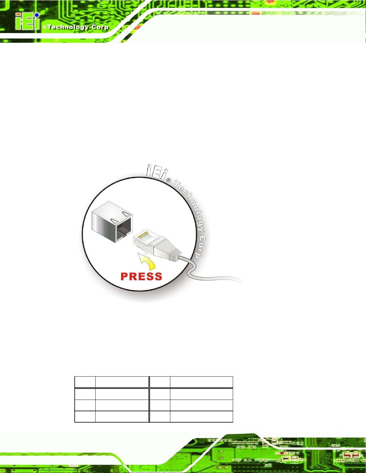
AFL2-17A/AB-H61
Page 70
5.14.3 LAN Connection
There are two external R J-45 LAN con nectors. The RJ -45 connector ena bles connecti on
to an external networ k. To connect a LAN cab le with an RJ-45 connec tor, please follow
the instructions below.
Step 1: Locate the RJ-45 connectors. The locations of the LAN connectors are shown
in Chapter 1.
Step 2: Align the connectors. Align the RJ-45 connector on the LAN cable with one of
the RJ-45 connectors on the AFL2-17A/AB-H61. See Figure 5-24.
Figure 5-24: LAN Connection
Step 3: Insert the LAN cable RJ-45 connector. Once aligned, gently insert the LAN
cable RJ-45 connector into the external interface.
The pinouts of the RJ-45 LAN connectors are shown below.
Pin Description Pin Description
1 LAN1_MDI0+ 2 LAN1_MDI03 LAN1_MDI1+ 4 LAN1_MDI15 GND 6 GND
Page 91

AFL2-17A/AB-H61
Page 71
Pin Description Pin Description
7 LAN1_MDI2+ 8 LAN1_MDI29 LAN1_MDI3+ 10 LAN1_MDI311 GND 12 GND
13 NC 14 NC
L1 LAN1_LINK100 L2 LAN1_LINK1000
L3 LAN1_ACT-1 L4 POWER
Table 5-2: LAN1 Pinouts
Pin Description Pin Description
1 LAN2_MDI0+ 2 LAN2_MDI03 LAN2_MDI1+ 4 LAN2_MDI15 GND 6 GND
7 LAN12_MDI2+ 8 LAN2_MDI29 LAN2_MDI3+ 10 LAN2_MDI311 GND 12 GND
13 NC 14 NC
L1 LAN12_LINK100 L2 LAN2_LINK1000
L3 LAN2_ACT-1 L4 POWER
Table 5-3: LAN2 Pinouts
5.14.4 Serial Device Connection
There are two external RS-232 DB-9 connectors and one RS-422/485 DB-9 connector for
serial device connection. Follow the steps below to connect a serial device to the
AFL2-17A/AB-H61.
Step 1: Locate the DB-9 connector. The locations of the DB-9 connectors are shown
in Chapter 1.
Step 2: Insert the serial connector. Insert the DB-9 connector of a serial device into
the DB-9 connector on the bottom panel. See Figure 5-25.
Page 92

AFL2-17A/AB-H61
Page 72
Figure 5-25: DB-9 Serial Port Connector
Step 3: Secure the connector. Secure the serial device connector to the external
interface by tightening the two retention screws on either side of the connector .
Step 0:
The pinouts of the RS-232 serial ports are shown below.
Pin Description Pin Description
1 NDCD1 2 NSIN1
3 NSOUT1 4 NDTR1
5 GND 6 NDSR1
7 NRTS1 8 NCTS1
9 XRI1 10 NDCD2
11 NSIN2 12 NSOUT2
13 NDTR2 14 GND
15 NDSR2 16 NRTS2
17 NCTS2 18 XRI2
Table 5-4: RS-232 Serial Port s Pinouts (COM1, COM2)
Page 93
AFL2-17A/AB-H61
Page 73
The pinouts of the RS-422/485 serial ports are shown below.
Pin Description Pin Description
1 RXD485+ 2 RXD485#
3 TXD485+ 4 TXD485#
Table 5-5: RS-422/485 Serial Port Pinouts (COM3)
5.14.5 USB Device Connection
NOTE:
User must install the USB 3.0 driver before connecting a USB device to
the system or else the system may not recognize the connected
device.
There are three USB 2.0 connectors and two USB 3.0 connectors on the
AFL2-17A/AB-H61. To connect a USB device, please follow the instructions below.
Step 1: Locate the USB connectors. The locations of the USB connectors are shown
in Chapter 1.
Step 2: Align the connectors. Align the USB device connector with one of the
connectors on the bottom panel. See Figure 5-26.
Page 94
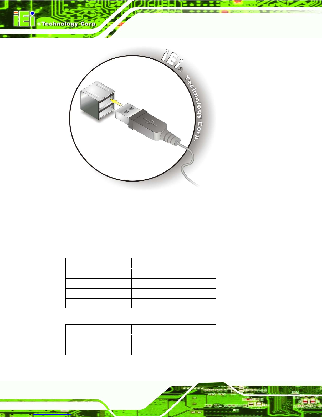
AFL2-17A/AB-H61
Page 74
Figure 5-26: USB Device Connection
Step 3: Insert the device connector. Once align ed, ge ntly insert the USB device
connector into the onboard connector. Step 0:
The pinouts of the USB 2.0 connectors are shown below.
Pin Description Pin Description
1 POWER 2 -DATA0
3 +DATA0 4 GND
5 POWER 6 -DATA1
7 +DATA1 8 GND
Table 5-6: USB 2.0 connectors Pinouts (bottom panel)
Pin Description Pin Description
1 POWER 2 -DATA2
3 +DATA2 4 USB20_GND
Table 5-7: USB 2.0 connectors Pinouts (left side panel)
Page 95
AFL2-17A/AB-H61
Page 75
The pinouts of the USB 3.0 connectors are shown below.
Step 1:
Pin Description Pin Description
1 USB3_PWR1 2 USB2P0_DM1_L
3 USB2P0_DP1_L 4 GND
5 USB3P0_RXDN1_L 6 USB3P0_RXDP1_L
7 GND 8 USB3P0_TXDN1_C_L
9 USB3P0_TXDP1_C_L 10 USB3_PWR2
11 USB2P0_DM2_L 12 USB2P0_DP2_L
13 GND 14 USB3P0_RXDN2_L
15 USB3P0_RXDP2_L 16 GND
17 USB3P0_TXDN2_C_L 18 USB3P0_TXDP2_C_L
Table 5-8: USB 3.0 connectors Pinouts
5.14.6 VGA Monitor Connection
The AFL2-17A/AB-H61 has a single fem ale DB-15 connector on the ex ternal peripheral
interface panel. The DB-15 connector is connec ted to a CR T or VGA monitor. To connect
a monitor to the AFL2-17A/AB-H61, please follow the instructions below.
Step 1: Locate the female DB-15 connector. The location of the female DB-15
connector is shown in Chapter 1.
Step 2: Align the VGA connector. Align the male DB-15 connector on the VGA screen
cable with the female DB-15 connector on the external peripheral interface.
Step 3: Insert the VGA connector. Once the connectors are properly aligned with the
insert the male connector from the VGA screen into the female connector on the
AFL2-17A/AB-H61. See Figure 5-27.
Page 96

AFL2-17A/AB-H61
Page 76
Figure 5-27: VGA Connector
Step 4: Secure the connector. Secure the DB-15 VGA connector from the VGA
monitor to the external interface by tightening the two retention screws on either
side of the connector.
The pinouts of the VGA connector is shown below.
Pin Description Pin Description
1 CRT_RED 2 CRT_GREEN
3 CRT_BLUE 4 NC
5 GND 6 GND
7 GND 8 GND
9 CRT_VCC 10 CRT_PLUG#
11 NC 12 CRT_DDC_DATA
13 CRT_HSYNC 14 CRT_VSYNC
15 CRT_DDC_CLK
Table 5-9: VGA Pinouts
Page 97

AFL2-17A/AB-H61
Page 77
Chapter
6
6 System Motherboard
Page 98

AFL2-17A/AB-H61
Page 78
6.1 Overview
This chapter details all the jumpers and connectors of the system motherboard.
6.1.1 Layout
The figures below show all the connectors and jumpers of the system motherboard..
Figure 6-1: Connectors and Jumpers (front)
Page 99

AFL2-17A/AB-H61
Page 79
Figure 6-2: Connectors and Jumpers (rear)
6.1.2 Peripheral Interface Connectors
The table below lists all the connectors on the board.
Connector Type Label
Auto-dimming connector 10-pin header JP7
Battery connector 2-pin wafer BAT2
BIOS programming connector 6-pin wafer JSPI1
Bluetooth connector 4-pin wafer BLUETOOTH1
CPU fan connector 4-pin wafer CPU_FAN1
DDR3 SO-DIMM slots DDR3 SO-DIMM slot DIMM1,
DIMM2
Debug port connector 9-pin wafer DEBUGCN1
Digital microphone connector 4-pin wafer DMIC1
Page 100

AFL2-17A/AB-H61
Page 80
Connector Type Label
EC debug connector 18-pin header CN15
EC programming connector 6-pin wafer JSPI2
Hotkey connector 9-pin wafer HOTKEYCN1
Hotkey LED connector 8-pin wafer HOTKEYLEDCN1
JSATA connector 20-pin connector JSATA3
K type thermocouple connector 2-pin wafer CN13, CN14
LVDS connector 30-pin crimp LVDS1
LVDS backlight inverter connector 6-pin wafer INVERTER1
LED connector 16-pin header LEDCN1
Light bar connector 6-pin wafer CN1, CN2,
CN3, CN4
LOGO LED connector 2-pin wafer LOGO_LED
Mini USB connector 4-pin wafer MINUSB1,
MINUSB2
PCIe Mini Card Slot PCIe mini card slot MINI_PCIE1,
MINI_PCIE2
Power button connector 2-pin wafer PW_BT1
RFID connector 4-pin wafer RFID_USB1
SATA 3Gb/s drive connector 7-pin SATA connector SATA1
SATA power connector 2-pin wafer CN8
Speaker connector 4-pin wafer SPK_CN13
Touch panel connector 9-pin wafer TS1
Touch panel connector 4-pin wafer TOUCH1
TPM connector 20-pin header TPM1
Web camera connector 4-pin wafer WEBCAMER1
AT/ATX switch switch AT/ATX2
Clear CMOS switch switch RTC_SW1
 Loading...