

IEI Technology AFL2-12A-HM65/PC-EM-R11, AFL2-12A-HM65/PC-MF-R11, AFL2-12A-HM65/PC-R11, AFL2-12A-HM65/R-EM-R11, AFL2-12A-HM65/R-MF-R11 User Manual
...Page 1

IEI Technology Corp.
User Manual
AFL2-12A-HM65 Series Panel PC
MODEL:
AFL2-12A-HM65 Series
Flat Bezel Panel PC with Intel® Sandy Bridge Mobile CPU,
TFT LCD, Wi-Fi, Touch Screen, RFID Reader, GbE LAN,
RS-232/422/485, Camera, RoHS
User Manual
Rev. 1.10 - 10 July, 2012
Page I
Page 2

Date Version Changes
AFL2-12A-HM65 Series Panel PC
Revision
10 July, 2012 1.10
8 December, 2011 1.00
Updated for R11 (remove second LAN function)
Initial release
Page II
Page 3

AFL2-12A-HM65 Series Panel PC
COPYRIGHT NOTICE
The information in this document is subject to change without prior notice in order to
improve reliability, design and function and does not represent a commitment on the part
of the manufacturer.
In no event will the manufacturer be liable for direct, indirect, special, incidental, or
consequential damages arising out of the use or inability to use the product or
documentation, even if advised of the possibility of such damages.
This document contains proprietary information protected by copyright. All rights are
Copyright
reserved. No part of this manual may be reproduced by any mechanical, electronic, or
other means in any form without prior written permission of the manufacturer.
TRADEMARKS
All registered trademarks and product names mentioned herein are used for identification
purposes only and may be trademarks and/or registered trademarks of their respective
owners.
Page III
Page 4

AFL2-12A-HM65 Series Panel PC
WARNING:
This equipment has been tested and found to comply with the limits for a Class A digital
device, pursuant to Part 15 of the FCC Rules. These limits are designed to provide
reasonable protection against harmful interference in a residential installation. This
equipment generates, uses and can radiate radio frequency energy and, if not installed
and used in accordance with the instructions, may cause harmful interference to radio
communications. However, there is no guarantee that interference will not occur in a
particular installation. If this equipment does cause harmful interference to radio or
television reception, which can be determined by turning the equipment off and on, the
user is encouraged to try to correct the interference by one or more of the following
measures:
Reorient or relocate the receiving antenna.
Increase the separation between the equipment and receiver.
Connect the equipment into an outlet on a circuit different from that to which
the receiver is connected.
Consult the dealer or an experienced radio/TV technician for help.
FCC Caution: Any changes or modifications not expressly approved by the party
responsible for compliance could void the user's authority to operate this equipment.
This device and its antenna(s) must not be co-located or operating in conjunction with any
other antenna or transmitter.
IMPORTANT NOTE:
For products available in the USA/Canada market, only channel 1~11 can be operated.
Selection of other channels is not possible.
This device complies with Part 15 of the FCC Rules. Operation is subject to the following
two conditions: (1) This device may not cause harmful interference, and (2) this device
Page IV
must accept any interference received, including interference that may cause undesired
operation.
Page 5

AFL2-12A-HM65 Series Panel PC
Table of Contents
1 INTRODUCTION.......................................................................................................... 1
1.1 AFL2-12A-HM65 FLAT BEZEL PANEL PC OVERVIEW............................................... 2
1.1.1 Model Variations................................................................................................ 3
1.1.2 Features ............................................................................................................. 3
1.1.3 Applications ....................................................................................................... 3
1.2 EXTERNAL OVERVIEW................................................................................................ 4
1.2.1 Front Panel........................................................................................................ 4
1.2.1.1 LED Indicators............................................................................................ 5
1.2.2 Rear Panel ......................................................................................................... 7
1.2.3 I/O Interface Panel ............................................................................................ 8
1.2.4 Top Panel and Side Panels................................................................................. 9
1.3 INTERNAL OVERVIEW............................................................................................... 10
1.4 SYSTEM SPECIFICATIONS.......................................................................................... 10
2 DETAILED SPECIFICATIONS ................................................................................ 13
2.1 DIMENSIONS............................................................................................................. 14
2.2 INTEL® SANDY BRIDGE MOBILE PROCESSOR.......................................................... 16
2.3 MOTHERBOARD COMPONENTS................................................................................. 16
2.3.1 Memory Support............................................................................................... 16
2.3.1.1 Installed Memory...................................................................................... 16
2.3.2 Storage Capacity.............................................................................................. 16
2.4 EXTERNAL PERIPHERAL INTERFACE CONNECTORS................................................... 16
2.4.1 Serial Port Connectors .................................................................................... 16
2.4.2 LAN Connectivity............................................................................................. 17
2.4.3 External USB Connectors................................................................................ 17
2.5 TOUCHSCREEN LCD................................................................................................. 18
2.5.1 Monitor ............................................................................................................ 18
2.5.2 Touch-Screen Module....................................................................................... 19
2.6 AUDIO...................................................................................................................... 19
2.6.1 Audio Codec Controller................................................................................... 19
2.6.2 Stereo Speakers ................................................................................................ 19
Page V
Page 6

2.7 SYSTEM POWER ....................................................................................................... 19
2.7.1 Power Mode..................................................................................................... 19
2.7.1.1 ATX Power Mode (Default)...................................................................... 20
2.7.1.2 AT Power Mode ........................................................................................ 20
2.7.2 Power Adapter................................................................................................. 20
3 UNPACKING............................................................................................................... 21
3.1 UNPACKING.............................................................................................................. 22
3.1.1 Packing List ..................................................................................................... 22
4 INSTALLATION ......................................................................................................... 26
4.1 ANTI-STATIC PRECAUTIONS...................................................................................... 27
4.2 INSTALLATION PRECAUTIONS ................................................................................... 27
4.3 INST ALLATION AND CONFIGURATION STEPS............................................................. 28
4.4 HDD INSTALLATION................................................................................................. 28
AFL2-12A-HM65 Series Panel PC
4.5 AT/ATX MODE SELECTION...................................................................................... 31
4.5.1 AT Power Mode................................................................................................ 32
4.5.2 ATX Power Mode............................................................................................. 32
4.6 POWERING ON THE SYSTEM..................................................................................... 33
4.7 POWERING OFF THE SYSTEM.................................................................................... 33
4.8 MOUNTING THE SYSTEM .......................................................................................... 33
4.8.1 Wall Mounting.................................................................................................. 34
4.8.2 Stand Mounting................................................................................................ 37
4.8.3 Arm Mounting .................................................................................................. 37
4.8.4 Cabinet and Rack Installation ......................................................................... 38
4.9 BOTTOM PANEL CONNECTORS ................................................................................. 41
4.9.1 LAN Connection............................................................................................... 41
4.9.2 Serial Device Connection ................................................................................ 41
4.9.2.1 DB-9 Serial Port Connection.................................................................... 42
4.9.2.2 RJ-45 Serial Port Connection.................................................................... 42
4.9.3 RS-422/485 Serial Port Connection................................................................. 44
4.9.4 USB Device Connection................................................................................... 46
4.9.5 HDMI Device Connection................................................................................ 47
5 SYSTEM MAINTENANCE ....................................................................................... 49
5.1 SYSTEM MAINTENANCE INTRODUCTION .................................................................. 50
Page VI
Page 7

AFL2-12A-HM65 Series Panel PC
5.2 ANTI-STATIC PRECAUTIONS...................................................................................... 50
5.3 TURN OFF THE POWER.............................................................................................. 51
5.4 OPENING THE SYSTEM.............................................................................................. 51
5.4.1 Removing the Back Cover................................................................................ 51
5.4.2 Removing the Internal Aluminum Cover.......................................................... 52
5.5 REPLACING COMPONENTS........................................................................................ 53
5.5.1 Memory Module Replacement ......................................................................... 53
5.5.2 WLAN Card Replacement................................................................................ 54
5.6 REINST ALLING THE COVERS..................................................................................... 57
6 AMI BIOS SETUP....................................................................................................... 58
6.1 INTRODUCTION......................................................................................................... 59
6.1.1 Starting Setup................................................................................................... 59
6.1.2 Using Setup...................................................................................................... 59
6.1.3 Getting Help..................................................................................................... 60
6.1.4 Unable to Reboot After Configuration Changes.............................................. 60
6.1.5 BIOS Menu Bar................................................................................................ 60
6.2 MAIN........................................................................................................................ 61
6.3 ADVANCED............................................................................................................... 62
6.3.1 ACPI Settings................................................................................................... 63
6.3.2 CPU Configuration.......................................................................................... 64
6.3.3 SATA Configuration ......................................................................................... 66
6.3.4 USB Configuration........................................................................................... 68
6.3.5 Super IO Configuration ................................................................................... 71
6.3.5.1 Serial Port n Configuration....................................................................... 72
6.3.6 H/W Monitor.................................................................................................... 73
6.3.6.1 Fan 1 Configuration.................................................................................. 74
6.3.7 Serial Port Console Redirection...................................................................... 75
6.4 IEI FEATURE ............................................................................................................. 77
6.5 CHIPSET ................................................................................................................... 78
6.5.1 NorthBridge Configuration.............................................................................. 79
6.5.1.1 Graphics Configuration............................................................................. 80
6.5.2 South Bridge Configuration............................................................................. 82
6.5.3 Graphics Configuration................................................................................... 84
6.6 BOOT........................................................................................................................ 87
Page VII
Page 8

6.7 SECURITY................................................................................................................. 89
6.8 SAVE & EXIT ............................................................................................................ 91
7 SOFTWARE DRIVERS.............................................................................................. 93
7.1 AVAILABLE SOFTWARE DRIVERS.............................................................................. 94
7.2 ST ARTING THE DRIVER PROGRAM ............................................................................ 94
7.3 CHIPSET DRIVER INSTALLATION............................................................................... 94
7.4 GRAPHICS DRIVER INSTALLATION............................................................................ 98
7.5 AUDIO DRIVER INSTA LLATION ............................................................................... 102
7.6 TOUCH SCREEN DRIVER......................................................................................... 104
7.6.1 Calibrating the Touch Screen......................................................................... 108
7.7 AMCAP DRIVER INSTALLATION ..............................................................................110
7.8 USB 3.0 DRIVER INSTALLATION .............................................................................112
A INTERFACE CONNECTORS .................................................................................115
AFL2-12A-HM65 Series Panel PC
A.1 PERIPHERAL INTERFACE CONNECTORS...................................................................116
B SAFETY PRECAUTIONS....................................................................................... 122
B.1 SAFETY PRECAUTIONS........................................................................................... 123
B.1.1 General Safety Precautions........................................................................... 123
B.1.2 CPU Temperature Warning ........................................................................... 124
B.1.3 Anti-static Precautions.................................................................................. 124
B.1.4 Product Disposal........................................................................................... 125
B.2 MAINTENANCE AND CLEANING PRECAUTIONS ...................................................... 125
B.2.1 Maintenance and Cleaning............................................................................ 125
B.2.2 Cleaning Tools............................................................................................... 126
C BIOS CONFIGURATION OPTIONS..................................................................... 127
C.1 BIOS CONFIGURATION OPTIONS ........................................................................... 128
D ONE KEY RECOVERY........................................................................................... 130
D.1 ONE KEY RECOVERY INTRODUCTION.................................................................... 131
D.1.1 System Requirement...................................................................................... 132
D.1.2 Supported Operating System......................................................................... 133
D.2 SETUP PROCEDURE FOR WINDOWS........................................................................ 134
D.2.1 Hardware and BIOS Setup............................................................................ 135
Page VIII
Page 9

AFL2-12A-HM65 Series Panel PC
D.2.2 Create Partitions........................................................................................... 135
D.2.3 Install Operating System, Drivers and Applications..................................... 139
D.2.4 Building the Recovery Partition.................................................................... 140
D.2.5 Create Factory Default Image...................................................................... 142
D.3 AUTO RECOVERY SETUP PROCEDURE.................................................................... 147
D.4 SETUP PROCEDURE FOR LINUX.............................................................................. 151
D.5 RECOVERY TOOL FUNCTIONS................................................................................ 155
D.5.1 Factory Restore............................................................................................. 156
D.5.2 Backup System............................................................................................... 157
D.5.3 Restore Your Last Backup ............................................................................. 158
D.5.4 Manual.......................................................................................................... 159
D.6 RESTORE SYSTEMS FROM A LINUX SERVER THROUGH LAN.................................. 160
D.6.1 Configure DHCP Server Settings.................................................................. 161
D.6.2 Configure TFTP Settings............................................................................... 162
D.6.3 Configure One Key Recovery Server Settings............................................... 163
D.6.4 Start the DHCP, TFTP and HTTP................................................................. 164
D.6.5 Create Shared Directory ............................................................................... 164
D.6.6 Setup a Client System for Auto Recovery...................................................... 165
D.7 OTHER INFORMATIO N............................................................................................ 168
D.7.1 Using AHCI Mode or ALi M5283 / VIA VT6421A Controller ...................... 168
D.7.2 System Memory Requirement........................................................................ 170
E WATCHDOG TIMER............................................................................................... 171
F HAZARDOUS MATERIALS DISCLOSURE........................................................ 174
F.1 HAZARDOUS MATERIAL DISCLOSURE TABLE FOR IPB PRODUCTS CERTIFIED AS ROHS
COMPLIANT UNDER 2002/95/EC WITHOUT MERCURY................................................ 175
Page IX
Page 10

AFL2-12A-HM65 Series Panel PC
List of Figures
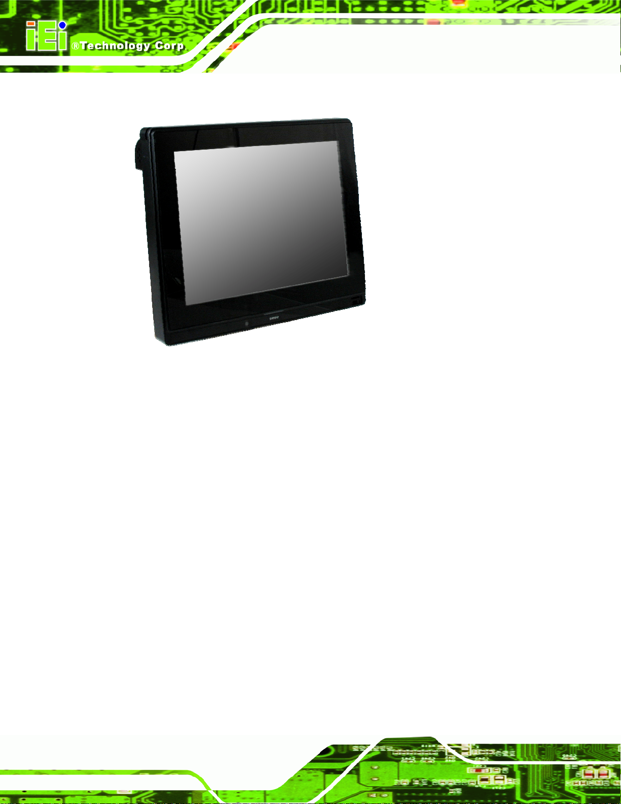
Figure 1-1: AFL2-12A-HM65 Flat Bezel Panel PC........................................................................2
Figure 1-2: AFL2-12A-HM65 Front View.......................................................................................4
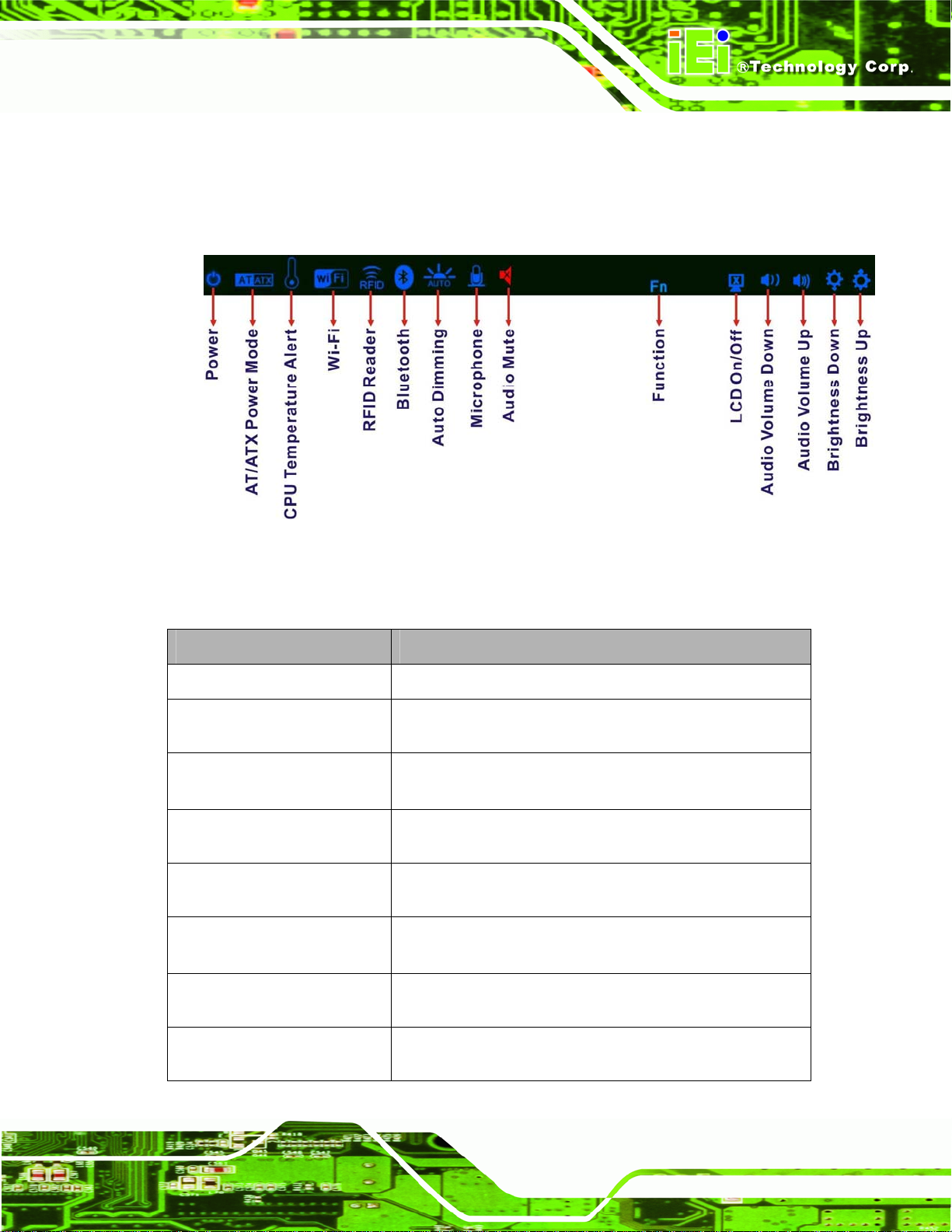
Figure 1-3: LED Indicators.............................................................................................................5
Figure 1-4: Function Keys .............................................................................................................6
Figure 1-5: AFL2-12A-HM65 Rear View ........................................................................................7
Figure 1-6: AFL2-12A-HM65 I/O Interface Panel..........................................................................9
Figure 1-7: Top Panel View............................................................................................................9
Figure 1-8: Side Panel Views.......................................................................................................10
Figure 2-1: AFL2-12A-HM65 Dimensions (mm) .........................................................................14
Figure 2-2: AFL2-12A-HM65 Dimensions (mm) cont.................................................................15
Figure 2-3: COM Ports..................................................................................................................17
Figure 2-4: RJ-45 Ethernet Connectors......................................................................................17
Figure 2-5: External USB Ports...................................................................................................18
Figure 2-6: LCD Screen................................................................................................................18
Figure 2-7: Audio Jack.................................................................................................................19
Figure 4-1: HDD Cover Retention Screws..................................................................................29
Figure 4-2: HDD Bracket Screw...................................................................................................29
Figure4-3: Removing the HDD Bracket ......................................................................................30
Figure 4-4: Inserting the HDD......................................................................................................30
Figure4-5: Securing the HDD.......................................................................................................31
Figure 4-6: AT/ATX Switch Location...........................................................................................32
Figure 4-7: Wall-mounting Bracket.............................................................................................34
Figure 4-8: Chassis Support Screws..........................................................................................36
Figure 4-9: Secure the Panel PC.................................................................................................36
Figure 4-10: Mounting screw location........................................................................................37
Figure 4-11: Arm Mounting Retention Screw Holes..................................................................38
Figure 4-12: The Rack/Cabinet Bracket......................................................................................39
Figure 4-13: Secure the Rack/Cabinet Bracket..........................................................................40
Figure 4-14: Install into a Rack/Cabinet .....................................................................................40
Figure 4-15: LAN Connection......................................................................................................41
Figure 4-16: DB-9 Serial Port Connector....................................................................................42
Page X
Page 11

AFL2-12A-HM65 Series Panel PC
Figure 4-17: Ethernet Connector.................................................................................................43
Figure 4-18: RJ-45 Serial Port Connector..................................................................................44
Figure 4-19: RS-422/485 Serial Port............................................................................................44
Figure 4-20: RS-422/485 Cable....................................................................................................45
Figure 4-21: DB-9 Connector.......................................................................................................45
Figure 4-22: USB Device Connection.........................................................................................47
Figure 4-23: HDMI Connection....................................................................................................48
Figure 5-1: Back Cover Retention Screws.................................................................................52
Figure 5-2: Internal Cover Retention Screws.............................................................................53
Figure 5-3: DDR SO-DIMM Module Installation..........................................................................54
Figure5-4: Removing the Antennas............................................................................................55
Figure5-5: Releasing the WLAN Card.........................................................................................55
Figure5-6: Removing the WLAN card.........................................................................................56
Figure5-7: Attaching the Antennas.............................................................................................57
Figure 7-1: Chipset Driver Screen...............................................................................................95
Figure 7-2: Chipset Driver Welcome Screen..............................................................................96
Figure 7-3: Chipset Driver License Agreement.........................................................................96
Figure 7-4: Chipset Driver Read Me File ....................................................................................97
Figure 7-5: Chipset Driver Setup Operations ............................................................................97
Figure 7-6: Chipset Driver Installation Finish Screen...............................................................98
Figure 7-7: Graphics Driver Read Me File..................................................................................99
Figure 7-8: Graphics Driver Setup Files Extracted ...................................................................99
Figure 7-9: Graphics Driver Welcome Screen........................................................................ 100
Figure 7-10: Graphics Driver License Agreement.................................................................. 100
Figure 7-11: Graphics Driver Read Me File............................................................................. 101
Figure 7-12: Graphics Driver Setup Operations..................................................................... 101
Figure 7-13: Graphics Driver Installation Finish Screen ....................................................... 102
Figure 7-14: Audio Driver Welcome Screen............................................................................ 103
Figure 7-15: Audio Driver Installation...................................................................................... 103
Figure 7-16: AC’97 Driver Installation Complete.................................................................... 104
Figure 7-17: Touch Screen Driver Welcome Screen.............................................................. 105
Figure 7-18: Touch Screen Driver License Agreement.......................................................... 105
Figure 7-19: Touch Screen Driver Choose Install Location.................................................. 106
Figure 7-20: Touch Screen Driver Installation Screen........................................................... 107
Figure 7-21: Touch Screen Driver Update Complete............................................................. 107
Page XI
Page 12

Figure 7-22: PenMount Monitor Icon....................................................................................... 108
Figure 7-23: PenMount Monitor Popup Menu......................................................................... 108
Figure 7-24: Configuration Screen........................................................................................... 109
Figure 7-25: Calibration Initiation Screen............................................................................... 109
Figure 7-26: Calibration Screen ............................................................................................... 110
Figure 7-27: AMCap Driver Welcome Screen ......................................................................... 111
Figure 7-28: AMCap Driver Choose Install Location.............................................................. 111
Figure 7-29: AMCap Driver Installation Complete.................................................................. 112
Figure 7-30: USB 3.0 Driver Welcome Screen........................................................................ 113
Figure 7-31: USB 3.0 Driver Choose Install Location ............................................................ 113
Figure 7-32: USB 3.0 Driver Choose Install Location ............................................................ 114
Figure 7-33: USB 3.0 Driver Installation Complete................................................................. 114
Figure D-1: IEI One Key Recovery Tool Menu........................................................................ 131
Figure D-2: Launching the Recovery Tool.............................................................................. 136
AFL2-12A-HM65 Series Panel PC
Figure D-3: Recovery Tool Setup Menu .................................................................................. 136
Figure D-4: Command Prompt ................................................................................................. 137
Figure D-5: Partition Creation Commands.............................................................................. 138
Figure D-6: Launching the Recovery Tool.............................................................................. 140
Figure D-7: Manual Recovery Environment for Windows..................................................... 140
Figure D-8: Building the Recovery Partition........................................................................... 141
Figure D-9: Press Any Key to Continue.................................................................................. 141
Figure D-10: Press F3 to Boot into Recovery Mode............................................................... 142
Figure D-11: Recovery Tool Menu ........................................................................................... 142
Figure D-12: About Symantec Ghost Window........................................................................ 143
Figure D-13: Symantec Ghost Path ......................................................................................... 143
Figure D-14: Select a Local Source Drive ............................................................................... 144
Figure D-15: Select a Source Partition from Basic Drive ...................................................... 144
Figure D-16: File Name to Copy Image to ............................................................................... 145
Figure D-17: Compress Image.................................................................................................. 145
Figure D-18: Image Creation Confirmation............................................................................. 146
Figure D-19: Image Creation Complete................................................................................... 146
Figure D-20: Image Creation Complete................................................................................... 146
Figure D-21: Press Any Key to Continue................................................................................ 147
Figure D-22: Auto Recovery Utility.......................................................................................... 148
Figure D-23: Launching the Recovery Tool............................................................................ 148
Page XII
Page 13

AFL2-12A-HM65 Series Panel PC
Figure D-24: Auto Recovery Environment for Windows ....................................................... 148
Figure D-25: Building the Auto Recovery Partition................................................................ 149
Figure D-26: Factory Default Image Confirmation ................................................................. 149
Figure D-27: Image Creation Complete................................................................................... 150
Figure D-28: Press any key to continue.................................................................................. 150
Figure D-29: Partitions for Linux.............................................................................................. 152
Figure D-30: Manual Recovery Environment for Linux ......................................................... 153
Figure D-31: Access menu.lst in Linux (Text Mode).............................................................. 154
Figure D-32: Recovery Tool Menu ........................................................................................... 154
Figure D-33: Recovery Tool Main Menu.................................................................................. 155
Figure D-34: Restore Factory Default...................................................................................... 156
Figure D-35: Recovery Complete Window.............................................................................. 157
Figure D-36: Backup System.................................................................................................... 157
Figure D-37: System Backup Complete Window ................................................................... 158
Figure D-38: Restore Backup................................................................................................... 158
Figure D-39: Restore System Backup Complete Window..................................................... 159
Figure D-40: Symantec Ghost Window ................................................................................... 159
Page XIII
Page 14

AFL2-12A-HM65 Series Panel PC
List of Tables
Table 1-1: AFL2-12A-HM65 Model Variations ..............................................................................3
Table 1-2: LED Indicators ..............................................................................................................6
Table 1-3: Function Key Descriptions..........................................................................................7
Table 1-4: System Specifications................................................................................................12
Table 4-1: Ethernet Connector Pinouts......................................................................................43
Table 4-2: RS-422/485 Serial Port Pinouts .................................................................................45
Table 4-3: DB-9 Connector Pinouts............................................................................................46
Table 6-1: BIOS Navigation Keys................................................................................................60
Page XIV
Page 15

AFL2-12A-HM65 Series Panel PC
Chapter
1
1 Introduction
Page 1
Page 16
AFL2-12A-HM65 Series Panel PC
1.1 AFL2-12A-HM65 Flat Bezel Panel PC Overview
Figure 1-1: AFL2-12A-HM65 Flat Bezel Panel PC
The AFL2-12A-HM65 is an Intel® Sandy Bridge Mobile CPU powered flat bezel panel PC
with a rich variety of functions and peripherals. The AFL2-12A-HM65 is designed for easy
and simplified integration into kiosk and point-of-sales (POS) applications.
An Intel® Sandy Bridge Mobile CPU coupled with an Intel® HM65 input/output controller
hub ensures optimal memory, graphics, and peripheral I/O support. The system comes
with 1.0 GB of preinstalled DDR3 SDRAM ensuring smooth data throughputs with reduced
bottlenecks and fast system ac cess.
Three serial ports, two external USB 2.0 ports and two external USB 3.0 ports ensure
simplified connectivity to a variety of external peripheral devices. Wi-Fi capabilities and the
RJ-45 Ethernet connector provide the system with smooth connection to an external LAN.
An optional MSR card reader can equip the syst em for scanning credit cards, ide ntification
cards, loyalty cards, gift cards, and more.
Page 2
Page 17
AFL2-12A-HM65 Series Panel PC
1.1.1 Model Variations
The model variations of the AFL2-12A-HM65 Series are listed below.
Model No. Touch Screen Type Optional Features
AFL2-12A-HM65/PC-EM-R11
AFL2-12A-HM65/PC-MF-R11
AFL2-12A-HM65/PC-R11
AFL2-12A-HM65/R-EM-R11
AFL2-12A-HM65/R-MF-R11
AFL2-12A-HM65/R-R11
Table 1-1: AFL2-12A-HM65 Model Variations
1.1.2 Features
The AFL2-12A-HM65 features are listed below:
12.1” 600 cd/m
Intel® Sandy Bridge Mobile CPU supported
Intel® HM65 chipset
1.0 GB 800 MHz DDR3 SO-DIMM preinstalled (4 GB maximum)
2
XGA LCD
Projective capacitive EM card reader
Projective capacitive MIFARE card reader
Projective capacitive N/A
5-Wire Resistive EM card reader
5-Wire Resistive MIFARE card reade r
5-Wire Resistive N/A
RFID module compatible with EM or MIFARE cards
Watchdog timer that triggers a system reset if the system hang s for some
IP 64 compliant front panel
AT or ATX power mode
5-Wire Resistive or Projected Capacitive type touch screen
RoHS compliance
Auto-dimming control
1.3 megapixel webcam
1.1.3 Applications
AFL2-12A-HM65 Series panel PCs are elegant, sophisticated systems that can be easily
implemented in commercial, industrial and corporate environments.
reason
Page 3
Page 18

1.2 External Overview
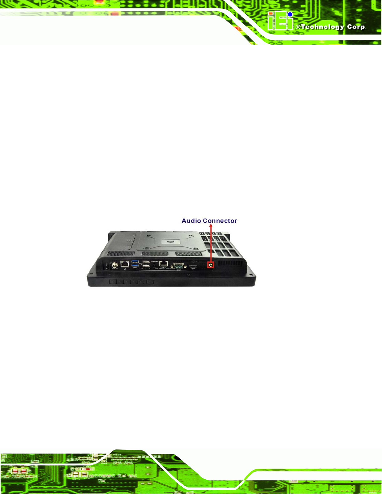
1.2.1 Front Panel
The front side of the AFL2-12A-HM65 is a flat bezel panel TFT LCD screen surrounded by
an ABS/PC plastic frame.
AFL2-12A-HM65 Series Panel PC
Page 4
Figure 1-2: AFL2-12A-HM65 Front View
Page 19
AFL2-12A-HM65 Series Panel PC
1.2.1.1 LED Indicators
There are fifteen LED indicator lights located along the front of the LCD screen (Figure
1-3).
Figure 1-3: LED Indicators
The descriptions of each LED indicator are listed below.
LED Indicator Description
Power
AT/ATX Mode
CPU Temperature Alert
Wi-Fi
RFID
Bluetooth
Auto-Dimming
Shows power on/off status.
Shows the power mode status. Controlled by the AT/ATX
power mode switch.
BLUE: CPU temperature is normal.
RED: CPU temperature is too high.
The Wi-Fi module is enabled or disabled. Controlled by the
BIOS. See Section
The optional RFID reader is enabled or disabled.
Controlled by the hot keys. See
The Bluetooth module is enabled or disabled.
Controlled by the BIOS. See Section
The auto-dimming function is enabled or disabled.
Controlled by the remote control
6.5.1.1
Table 1-3
6.5.1.1
Microphone
The microphone is enabled or disabled. Controlled by the
BIOS. See Section
6.5.1.1
Page 5
Page 20
LED Indicator Description
AFL2-12A-HM65 Series Panel PC
Audio Mute
Function
LCD On/Off
Audio Volume Down
Audio Volume Up
Brightness Down
Brightness Up
Table 1-2: LED Indicators
NOTE:
If the CPU temperature alert LED shows in red, the user must lower the
environments temperature or close some running applications to cool
Lights on when the audio is turned off. Controlled by the
hot keys. See
Shows the status of the function key below the LED
indicator. Blinks when the corresponding button is pushed.
Table 1-3
down the CPU.
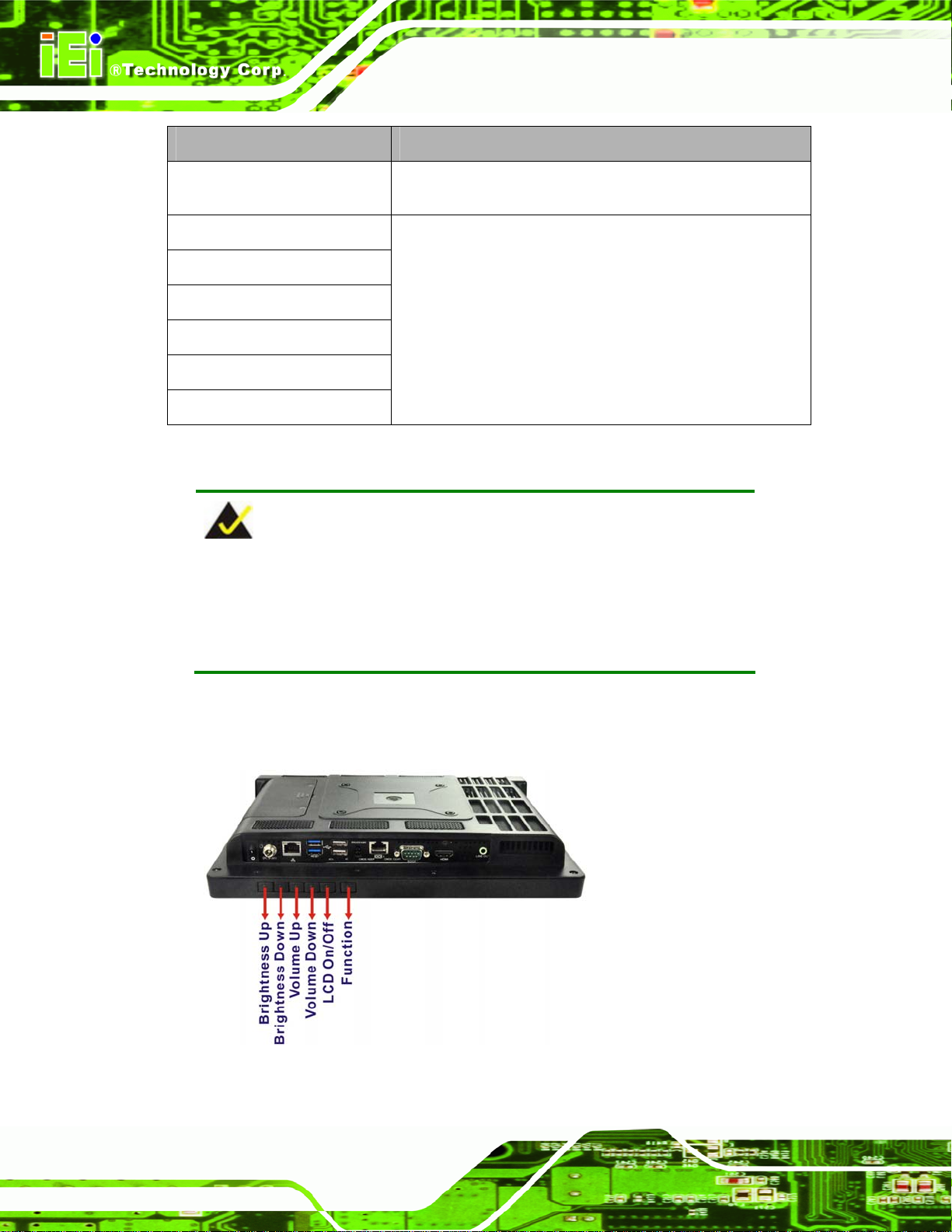
The corresponding Function Keys are located under the bottom right hand corner of the
LCD screen (
Figure 1-4).
Figure 1-4: Function Keys
Page 6
Page 21
AFL2-12A-HM65 Series Panel PC
The Function Keys are described in Table 1-3:
Key Combination Function Key Description
Fn + LCD On/Off
Fn + Audio Volume Down
Fn + Audio Volume Up
Fn + Brightness Down
Fn + Brightness Up
Table 1-3: Function Key Descriptions
RFID Enable/Disable
Audio Mute
Camera Enable/Disable
Mini USB / MicroSD Enable/Disable
Power On/Off
Note: To power on the system, hold down the Fn +
Brightness Up buttons for 3 seconds. To power down the
system, hold down the FN + Brightness Up buttons for six
seconds.
1.2.2 Rear Panel
The rear panel provides access to retention screw holes that support the wall mounting.
Refer to
Figure 1-5.
Figure 1-5: AFL2-12A-HM65 Rear View
Page 7
Page 22

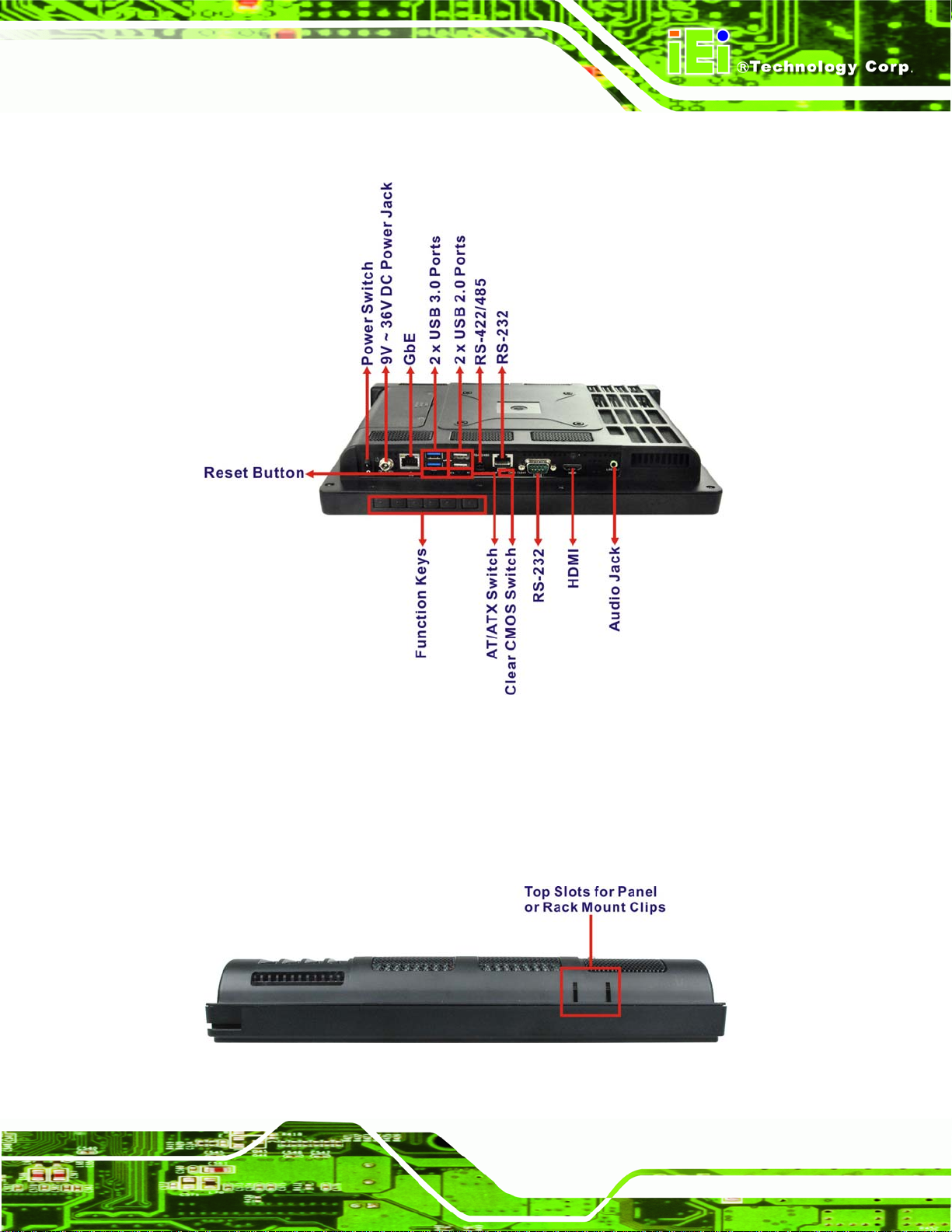
1.2.3 I/O Interface Panel
The I/O interface panel located on the bottom of the AFL2-12A-HM65 has the following
features:
1 x Audio jack
1 x 9V ~ 36V DC-IN power jack
1 x HDMI port
1 x RS-232 DB-9 connector
1 x RS-422/485 connector
1 x GbE connector
2 x USB 2.0 connectors
2 x USB 3.0 connectors
1 x Power switch
1 x Reset button
AFL2-12A-HM65 Series Panel PC
1 x Clear CMOS switch
1 x AT/ATX Switch
6 x Function Keys
Page 8
Page 23
AFL2-12A-HM65 Series Panel PC
The external I/O interface connector panel is shown in Figure 1-6.
Figure 1-6: AFL2-12A-HM65 I/O Interface Panel
1.2.4 Top Panel and Side Panels
The top panel and side panels of AFL2-12A-HM65 prov ide access to slots that su pport the
rack mount (
Figure 1-7: Top Panel View
Figure 1-7).
Page 9
Page 24
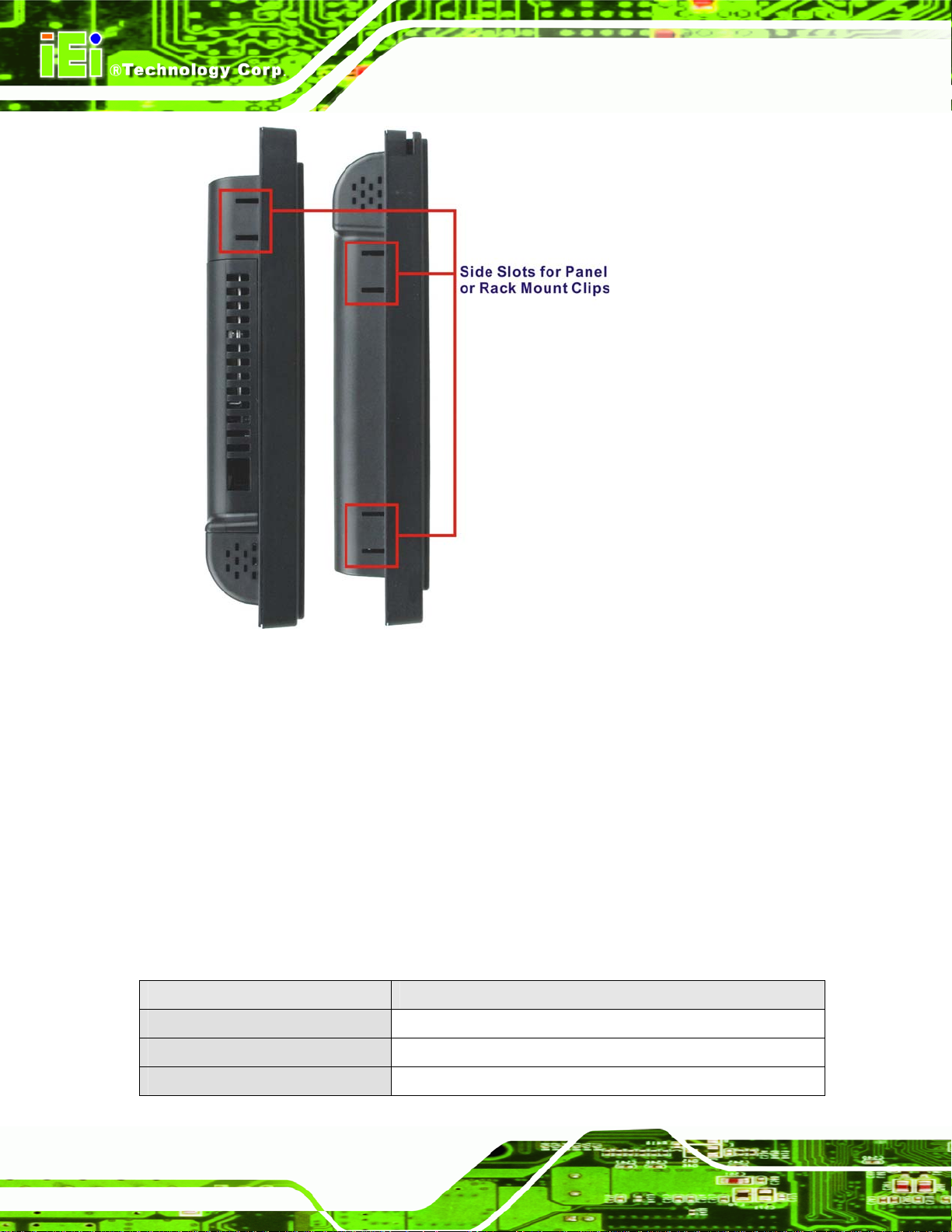
AFL2-12A-HM65 Series Panel PC
Figure 1-8: Side Panel Views
1.3 Internal Overview
The AFL2-12A-HM65 has the following components installed internally:
1 x Motherboard
1 x 1.0 GB 800 MHz DDR3 SO-DIMM
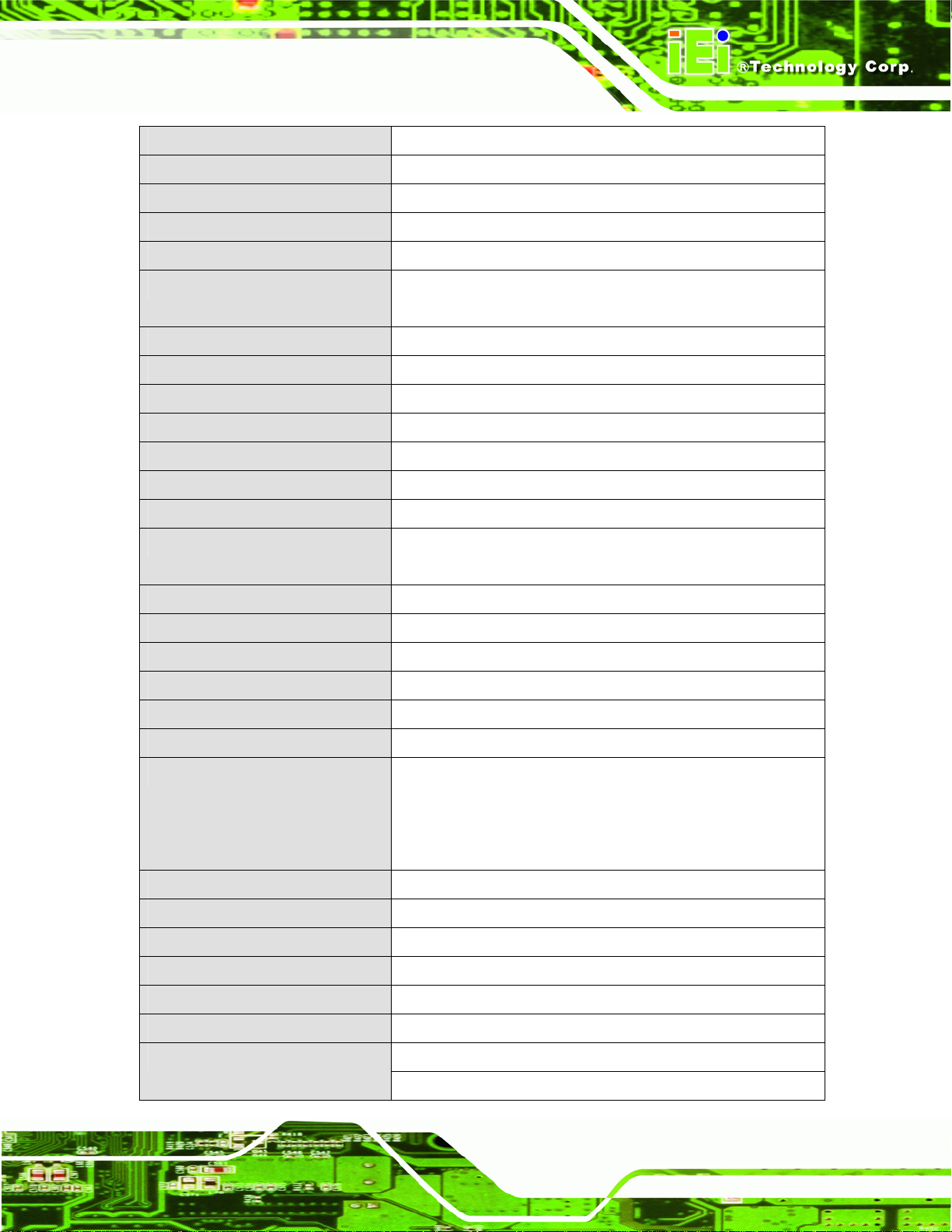
1.4 System Specifications
The technical specifications for the AFL2-12A-HM65 systems are listed in
Table 1-4.
Specification AFL2-12A-HM65
LCD Size 12.1”
Max. Resolution 1024 (W) x 768 (H)
Brightness (cd/m2) 600
Page 10
Page 25
AFL2-12A-HM65 Series Panel PC
Contrast Ratio 700:1
LCD Color 16.2M
Pixel Pitch (H x V) (mm) 0.240 (H) x 0.240 (V)
Viewing Angle (H-V) 176 / 176
Backlight MTBF (hr) 50,000
Touch Screen 5-Wire resistive type touchscreen (select models only)
Projected capacitive type touchscreen (select models only )
SBC Model AFL2MB-HM65
CPU Intel® Sandy Bridge Mobile CPU
Chipset Intel®HM65
Ethernet Realtek RTL8111E PCIe GbE controller supports ASF2.0
Memory One 204-pin DDR3 SO-DIMM slot pre-installed (4 GB system max.)
Expansion Mini PCIe slot for WiFi
Drive Bay One 2.5” SATA 3.0 HDD bay
SSD SATA SSD
One PCIe mini slot with SATA signal and IEI MiniDOM support
Watchdog Timer Software Programmable supports 1 sec. ~ 255 sec. system reset
Audio AMP 1.5 W + 1.5 W (built-in stereo speakers)
Wi-Fi Wi-Fi module 802.11 b/g/n
RFID EM or MIFARE card reader
MSR Module MSR card reader (Optional)
Construction Material ABS + PC plastic front frame
Mounting Wall
Rack
Stand
Arm (VESA 100 mm x 100 mm)
Front Panel Color Black
Net Weight 3.8 kg / 6.1 kg
Dimensions (W x H x D) (mm) 310 x 265 x 52.6
Operation Temperature -20ºC ~ 50ºC
Storage Temperature -20ºC ~ 60ºC
IP level IP 64 compliant front panel
90W Power Adapter
Input: 100V AC ~ 240V AC @ 50 / 60 Hz
Page 11
Page 26

Output: 19V DC
Power Requirement 9V ~ 36V DC
Power Consumption 51W
LED Functions Power / RFID / MIC / Auto-dimming / Wi-Fi / RFID device / AT/ATX
mode / Camera / Bluetooth / USB port / CPU temperature alert
AFL2-12A-HM65 Series Panel PC
I/O Ports and Switches
Table 1-4: System Specifications
1 x RS-232 (DB-9 connector)
1 x RS-232 (RJ-45 connector)
1 x RS-422/485 (4-pin box header)
1 x GbE LAN (RJ-45 connector)
2 x USB 2.0 connector
2 x USB 3.0 connector
1 x Mini USB 2.0 connector (on front panel)
1 x Audio jack (line-out)
1 x HDMI port
1 x SD card slot (on front panel)
1 x Reset button
1 x Power switch
1 x AT/ATX switch
1 x DC input jack
1 x Clear CMOS button
Page 12
Page 27

AFL2-12A-HM65 Series Panel PC
Chapter
2
2 Detailed Specifications
Page 13
Page 28

2.1 Dimensions
The AFL2-12A-HM65 dimensions are shown below.
Width: 310.0 mm
Height: 265.0 mm
Depth: 52.6 mm
AFL2-12A-HM65 Series Panel PC
Page 14
Figure 2-1: AFL2-12A-HM65 Dimensions (mm)
Page 29

AFL2-12A-HM65 Series Panel PC
Figure 2-2: AFL2-12A-HM65 Dimensions (mm) cont.
Page 15
Page 30

AFL2-12A-HM65 Series Panel PC
2.2 Intel® Sandy Bridge Mobile Processor
An Intel® Sandy Bridge Mobile processor is installed in the system. The Sandy Bridge
CPU interfaces with the HM65 chipset through a Direct Media Interface (DMI) with speed
of 5 GT/s and a Flexible Display Interface (FDI).
2.3 Motherboard Components
The following sections describe some of the features on the motherboard.
2.3.1 Memory Support
2.3.1.1 Installed Memory
One 204-pin 1.0 GB 800 MHz DDR3 SO-DIMM is installed in the AFL2-12A-HM65 and
controlled by the Intel® Sandy Bridge Mobile CPU installed on the internal motherboard.
2.3.2 Storage Capacity
The AFL2-12A-HM65 comes equipped with a 2.5” SATA 3.0 HDD drive bay which can be
easily accessed by removing two screws on the HDD cover.
2.4 External Peripheral Interface Connectors
The following section describes the external peripheral interface con nectors on the bottom
panel of the subsystem.
2.4.1 Serial Port Connectors
The AFL2-12A-HM65 has three serial ports. COM1 and CO M3 support o nly RS-232 seri al
communications. The other serial port (COM6) can be configured as an RS-422 or
RS-485 serial port. Enabling COM devices to be powered through the COM port
eliminates unnecessary and messy cabling.
Page 16
Page 31

AFL2-12A-HM65 Series Panel PC
Figure 2-3: COM Ports
2.4.2 LAN Connectivity
The AFL2-12A-HM65 has one RJ-45 LAN connector on the bottom panel.
Figure 2-4: RJ-45 Ethernet Connectors
The PCIe LAN from the Intel® HM65 chipset of the AFL2-12A-HM65 is interfaced to the
Realtek RTL8111E PCIe gigabit Ethernet (GbE) controllers. The RTL8111E controller is
connected directly to the RJ-45 connector on the bottom panel and provides external GbE
connectivity.
2.4.3 External USB Connectors
There are two USB 2.0 connectors and two USB 3.0 connectors on the bottom panel of
the AFL2-12A-HM65. All USB connectors are interfaced directly to the USB controllers on
the HM65 southbridge. All USB connectors are fully compliant with USB specification
Revision 2.0 and USB specification Revision 1.1 and can be interfaced to both USB 1.1
Page 17
Page 32
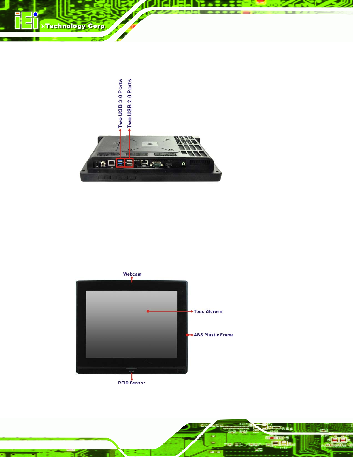
and USB 2.0 compliant devices. Only USB 3.0 connectors are compatible with USB 3.0
devices.
AFL2-12A-HM65 Series Panel PC
Figure 2-5: External USB Ports
2.5 Touchscreen LCD
2.5.1 Monitor
A 12.1” LCD screen is installed on the front of the AFL2-12A-HM65. The screen is shown
in
Figure 2-6 below.
Figure 2-6: LCD Screen
Page 18
Page 33
AFL2-12A-HM65 Series Panel PC
2.5.2 Touch-Screen Module
A controller for the touch screen is installed on the motherboard. The sensitive touch
screen is accurate, reliable and durable.
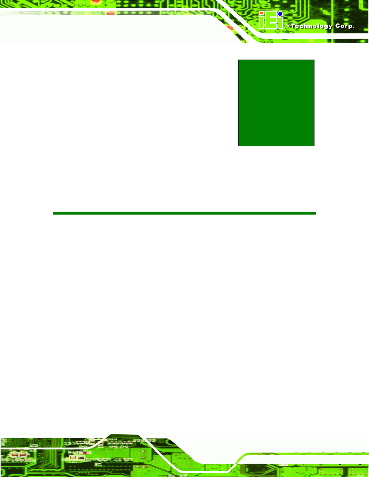
2.6 Audio
2.6.1 Audio Codec Controller
The integrated HD Audio compliant audio controller on the Intel® HM65 Southbridge is
integrated to a Realtek ALC888 audio codec. The Realtek ALC888 is connected to an
external audio jack, which is then connected to compliant audio devices. The Realtek
ALC888 is a 7.1+2 channel high definition audio codec with ten DAC channels. It supports
7.1 sound playback and 2 channels of independent stereo sound output. The audio
connector is shown in
Figure 2-7: Audio Jack
2.6.2 Stereo Speakers
Two internal 1.5 W stereo speakers on the sides of the AFL2-12A-HM65 are interfaced to
the system.
2.7 System Power
Figure 2-7.
2.7.1 Power Mode
The system can be run in the AT power mode or the ATX power mode. Both these power
modes are described below.
Page 19
Page 34

2.7.1.1 ATX Power Mode (Default)
With the ATX mode selected, the AFL2-12A-HM65 panel PC goes in a standby mode
when it is turned off. The panel PC can be easily turned on via network or a power switch
in standby mode. Remote power control is perfect for advertising applications since the
broadcasting time for each panel PC can be set individually and cont rolled remotely . Other
possible application includes
Security surveillance
Point-of-Sale (POS)
Advertising terminal
2.7.1.2 AT Power Mode
With the AT mode selected, the power is controlled by a central power unit rather than a
power switch. The AFL2-12A-HM65 panel PC turns on automatically when the power is
AFL2-12A-HM65 Series Panel PC
connected. The AT mode benefits a production line to control multiple panel PCs from a
central management center and other applications including:
ATM
Self-service kiosk
Plant environment monitoring system
Factory automation platform
Manufacturing shop flow
2.7.2 Power Adapter
The system is shipped with a 100 V to 240 V AC power adapter that has a maximum
power output of 65 W. The power adapter has a 19 V DC output connector.
Page 20
Page 35
AFL2-12A-HM65 Series Panel PC
Chapter
3
3 Unpacking
Page 21
Page 36
3.1 Unpacking
To unpack the flat bezel panel PC, follow the steps below:
WARNING!
The front side LCD screen has a protective plastic cover stuck to the
screen. Only remove the plastic cover after the flat bezel panel PC has
been properly installed. This ensures the screen is protected during the
installation process.
Step 1: Use box cutters, a knife or a sharp pair of scissors that seals the top side of the
external (second) box.
AFL2-12A-HM65 Series Panel PC
Step 2: Open the external (second) box.
Step 3: Use box cutters, a knife or a sharp pair of scissors that seals the top side of the
internal (first) box.
Step 4: Lift the monitor out of the boxes.
Step 5: Remove both polystyrene ends, one from each side.
Step 6: Pull the plastic cover off the flat bezel panel PC.
Step 7: Make sure all the components listed in the pa cking list are present. Step 0:
3.1.1 Packing List
The AFL2-12A-HM65 flat bezel panel PC is shipped with the following components:
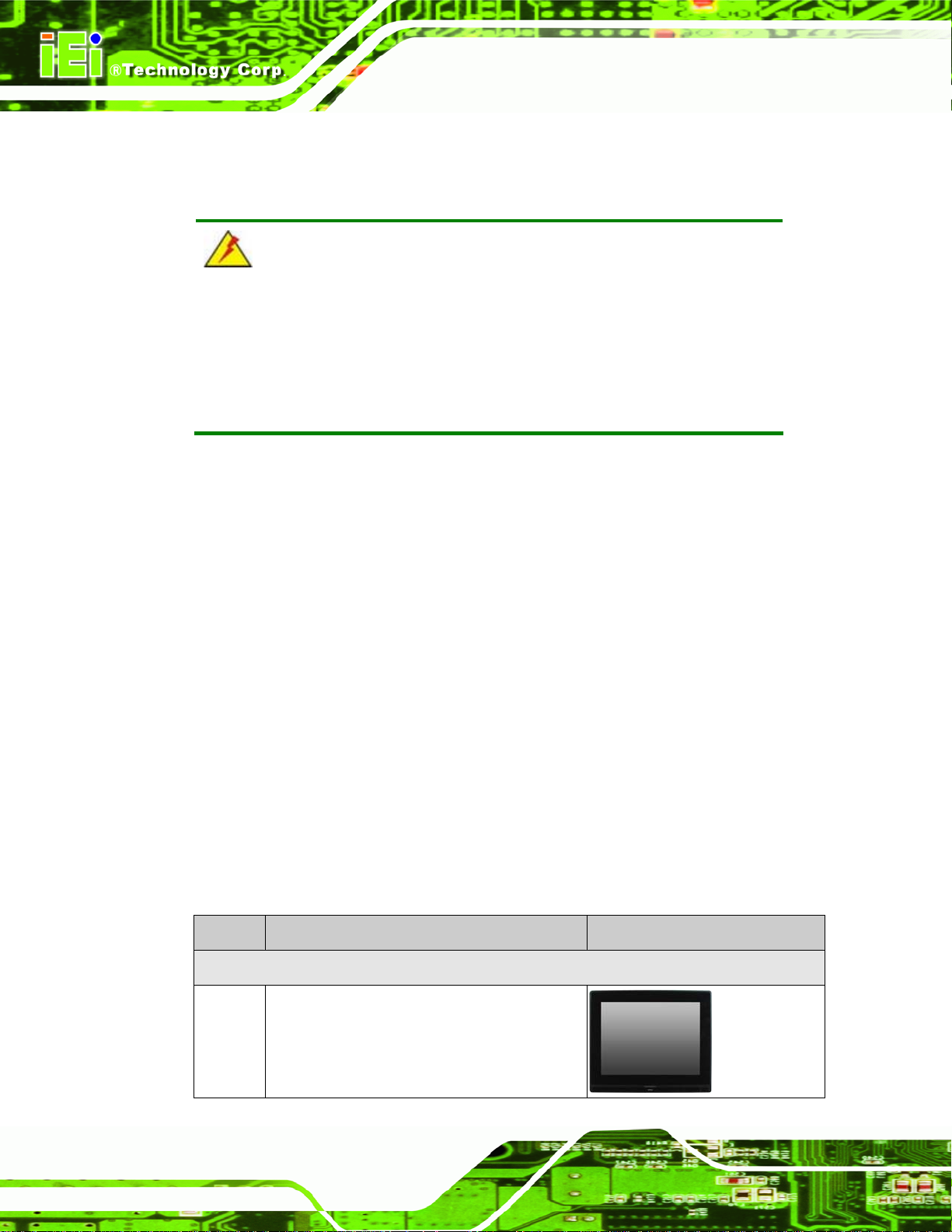
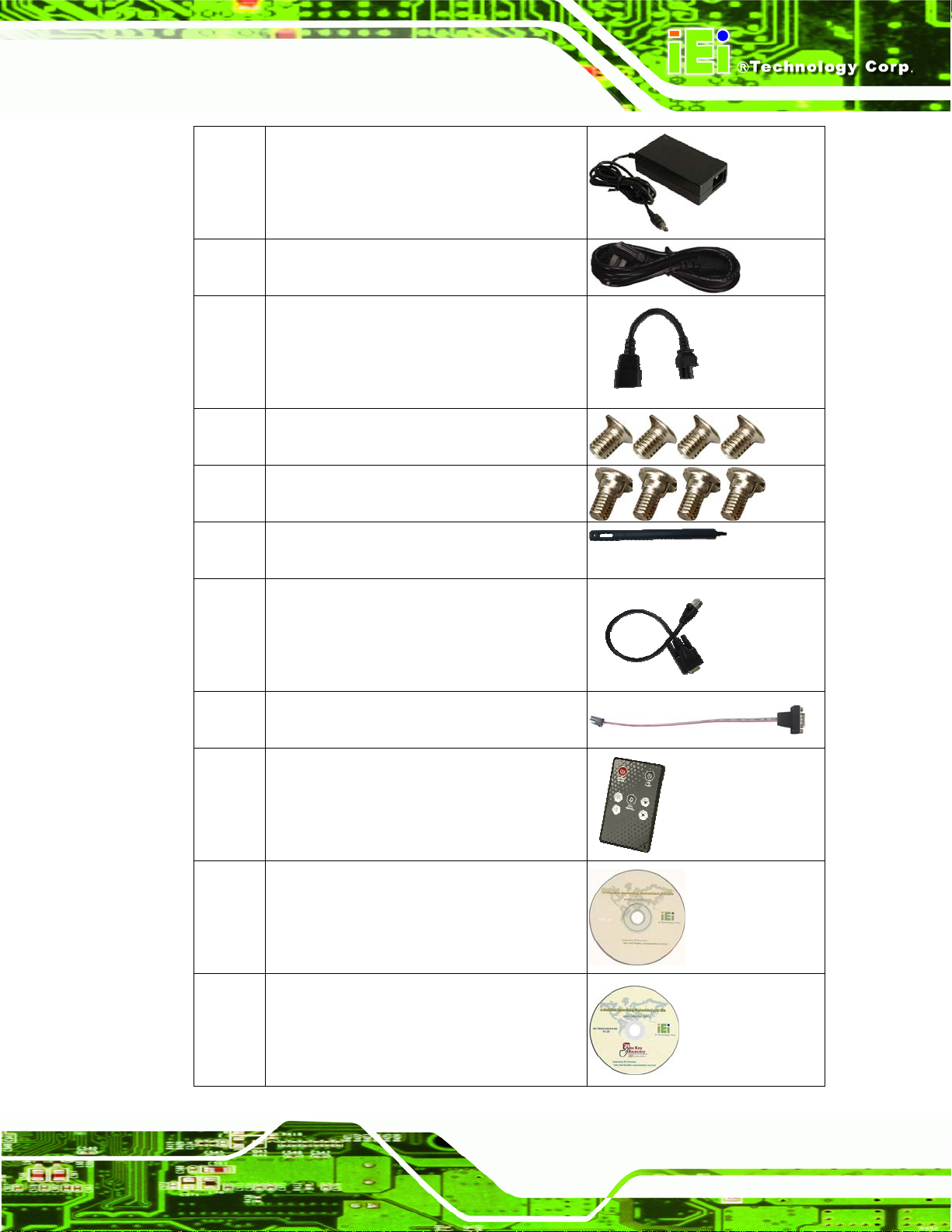
Quantity Item Image
Standard
Page 22
1 AFL2-12A-HM65 panel PC
Page 37
AFL2-12A-HM65 Series Panel PC
1 Power adapter
(P/N: 63040-010090-030-RS)
1 Power cord
(P/N: 32702-000401-100-RS)
1 Power transfer cord
(P/N: 32000-089400-RS)
4 M3 Screws Pack
(P/N: 44013-030041-RS)
4 M4 Screws Pack
(P/N: 44403-040061-RS)
1 Touch Pen
(P/N: 43125-0002C0-00-RS)
1 RJ-45 to DB-9 COM Port Cable
(P/N: 32005-000200-200-RS)
1 RS-422 cable
(P/N: 32205-002400-100-RS)
1 IR Remote Control
(P/N: 7Z000-SLPCB005-RS)
1 User manual CD and driver CD
1 One Key Recovery CD
(P/N: 7B000-000724-RS)
Page 23
Page 38
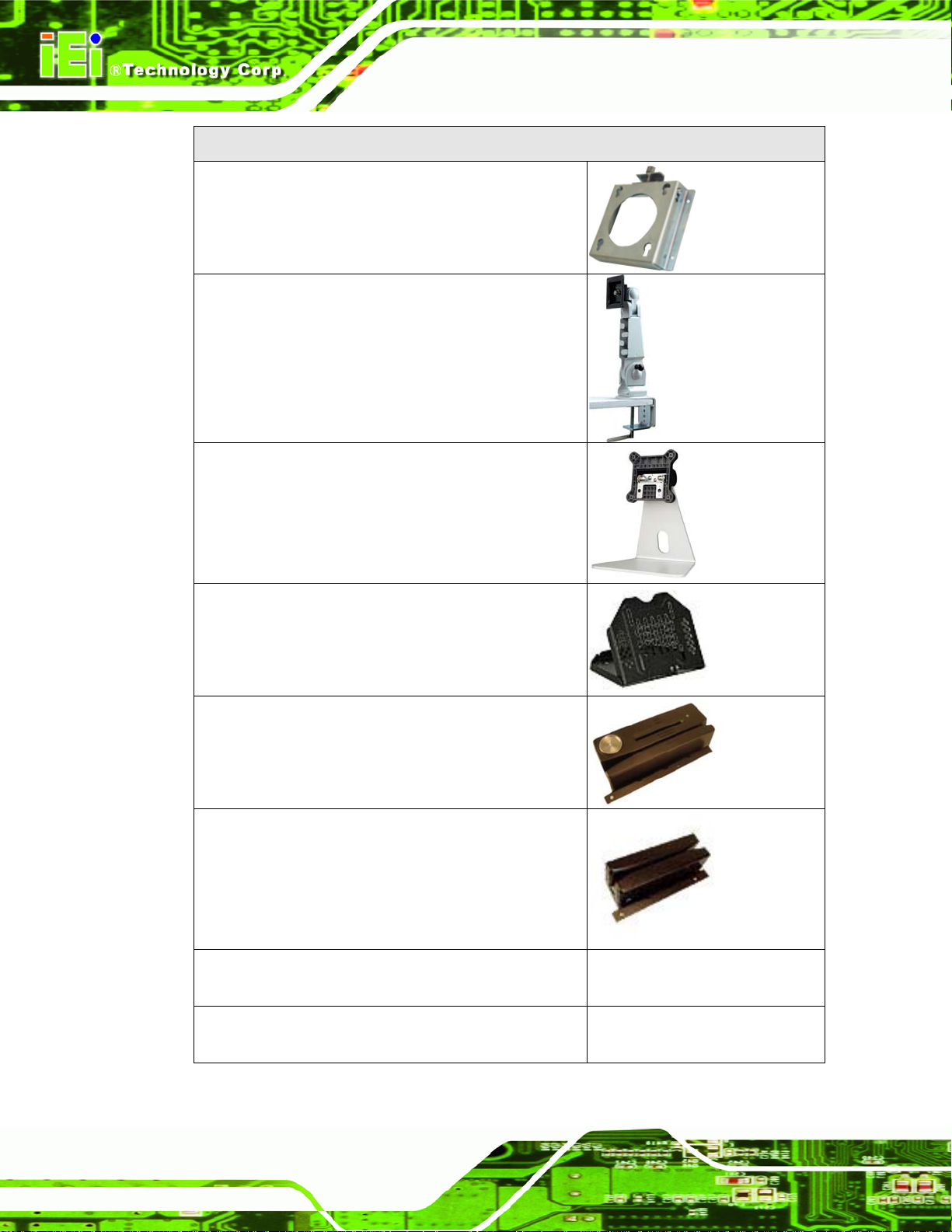
Optional
Wall mounting kit
(P/N: AFL WK-19/AFL WK-19B)
AFL2-12A-HM65 Series Panel PC
Arm
(P/N: ARM-11 -RS)
Stand
(P/N: STAND-A12)
V-Stand
(P/N: VSTAND-A12)
Hybrid Card Reader
(P/N: AFL2P-12AMSI-U-R10)
Magnetic Stripe Reader
(P/N: AFL2P-12AMSR-U-R10)
Rack Mounting Kit
(P/N: AFL2RK-12)
OS: Win CE 6.0 (128MB CF Card)
Page 24
(P/N: AFL2CF-12-HM65-CE060-128M-R10)
Page 39

AFL2-12A-HM65 Series Panel PC
OS: Win XPE (2GB CF Card)
(P/N: AFL2CF-12-HM65-XPE-2G-R10)
OS: Win XPE (4GB CF Card)
(P/N: AFL2CF-12-HM65-XPE-4G-R10)
OS: Linux (2GB CF Card)
(P/N: AFL2CF-12A-HM65-LNX-R10)
OS: Win 7 Embedded (4GB CF Card)
(P/N: AFL2CF-12-HM65-WES7P-4G-R10
AFL2CF-12-HM65-WES7E-4G-R10)
If any of these items are missing or damaged, contact the distributor or sales
representative immediately.
Page 25
Page 40

AFL2-12A-HM65 Series Panel PC
4 Installation
Chapter
4
Page 26
Page 41
AFL2-12A-HM65 Series Panel PC
4.1 Anti-static Precautions
WARNING:
Failure to take ESD precautions during the maintenance of the
AFL2-12A-HM65 may result in permanent damage to the
AFL2-12A-HM65 and severe injury to the user.
Electrostatic discharge (ESD) can cause serious damage to electronic components,
including the AFL2-12A-HM65. Dry climates are especially susceptible to ESD. It is
therefore critical that whenever the AFL2-12A-HM65 is accessed internally, or any other
electrical component is handled, the following anti-static precautions are strictly adhered
to.
Wear an anti-static wristband: - Wearing a simple anti-static wristband can
help to prevent ESD from damaging the board.
Self-grounding: - Before handling the board touch any grounded conducting
material. During the time the board is handled, frequently touch any
conducting materials that are connected to the ground.
Use an anti-static pad: - When configuring the AFL2-12A-HM65, place it on
an antic-static pad. This reduces the possibility of ESD damaging the
AFL2-12A-HM65.
Only handle the edges of the PCB: - When handling the PCB, hold the PCB
by the edges.
4.2 Installation Precautions
When installing the flat bezel panel PC, please follow the precautions listed below:
Power turned off: When installing the flat bezel panel PC, make sure the
power is off. Failing to turn off the power may cause severe injury to the body
and/or damage to the system.
Certified Engineers: Only certified engineers should install and modify
onboard functionalities.
Page 27
Page 42

Anti-static Discharge : If a user open the rear p anel of the flat bezel panel PC,
to configure the jumpers or plug in added peripheral devices, ground
themselves first and wear and anti-static wristband.
AFL2-12A-HM65 Series Panel PC
4.3 Installation and Configuration Steps
The following installation steps must be followed.
Step 1: Unpack the flat bezel panel PC
Step 2: Install an HDD
Step 3: Configure the system
Step 4: Connect peripheral devices to the bottom panel of the flat bezel panel PC
Step 5: Mount the flat bezel panel PC Step 0:
4.4 HDD Installation
WARNING:
Over-tightening back cover screws will crack the plastic frame.
Maximum torque for cover screws is 5 kg-cm (0.36 lb-ft/0.49 Nm).
To install the HDD into the AFL2-12A-HM65, please follow the steps below:
Step 1: Remove two (2) retention screws from the HDD cover (
Figure 4-1).
Page 28
Page 43

AFL2-12A-HM65 Series Panel PC
Figure 4-1: HDD Cover Retention Screws
Step 2: Remove the HDD cover from the device.
Step 3: Loosen the captive screw to release the HDD bracket from the chassis (
4-2).
Figure 4-2: HDD Bracket Screw
Figure
Page 29
Page 44

Step 4: Slide the HDD bracket out of the device as shown (Figureٛ 4-3).
AFL2-12A-HM65 Series Panel PC
Figure
Step 5: Insert an HDD into the bracket as shown (
ٛ 4-3: Removing the HDD Bracket
Figure 4-4).
Page 30
Figure 4-4: Inserting the HDD
Page 45

AFL2-12A-HM65 Series Panel PC
Step 6: Secure the HDD to the bracket using four (4) retention screws (two screws on
each side) (
Figure
Step 7: Slide the HDD module back into the device.
Step 8: Tighten the captive screw.
ٛ 4-5: Securing the HDD
Figureٛ 4-5).
Step 9: Replace the HDD cover and secure it using two (2) retention screws. Step 0:
4.5 AT/ATX Mode Selection
AT and ATX power modes can both be used on the AFL2-12A-HM65. The selection is
made through an AT/ATX switch located on the I/O panel (
or ATX mode, follow the steps below.
Step 1: Locate the AT/ATX switch on the I/O panel (
Figure 4-6). To select AT mode
Figure 4-6).
Page 31
Page 46

Figure 4-6: AT/ATX Switch Location
Step 2: Adjust the AT/ATX switch. Step 0:
4.5.1 AT Power Mode
With the AT mode selected, the power is controlled by a central power unit rather than a
AFL2-12A-HM65 Series Panel PC
power switch. The AFL2-12A-HM65 panel PC turns on automatically when the power is
connected. The AT mode benefits a production line to control multiple panel PCs from a
central management center and other applications including:
ATM
Self-service kiosk
Plant environment monitoring system
Factory automation platform
Manufacturing shop flow
4.5.2 ATX Power Mode
With the ATX mode selected, the AFL2-12A-HM65 panel PC goes in a standby mode
when it is turned off. The panel PC can be easily turned on via network or a power switch
in standby mode. Remote power control is perfect for advertising applications since the
broadcasting time for each panel PC can be set individually and cont rolled remotely . Other
possible application includes
Page 32
Security surveillance
Point-of-Sale (POS)
Advertising terminal
Page 47

AFL2-12A-HM65 Series Panel PC
4.6 Powering On the System
To power on the system, follow the steps below:
Step 1: Locate the Function and Brightness Up function keys. See Section
Step 2: Hold down the Function and Brightness Up buttons for three seconds to power
on the system. Step 0:
4.7 Powering Off the System
To power off the system, follow the steps below:
Step 1: Locate the Function and Brightness Up function keys. See Section
Step 2: Hold down the Function and Brightness Up buttons for six seconds to power off
the system. Step 0:
4.8 Mounting the System
WARNING!
1.2.1.1.
1.2.1.1.
When mounting the flat bezel panel PC onto an arm, onto the wall or onto a
panel, it is better to have more than one person to help with the installation
to make sure the panel PC does not fall down and get damaged.
The four methods of mounting the AFL2-12A-HM65 are listed below.
Wall mounting
Stand mounting
Arm mounting
Rack mounting
The four mounting methods are described below.
Page 33
Page 48
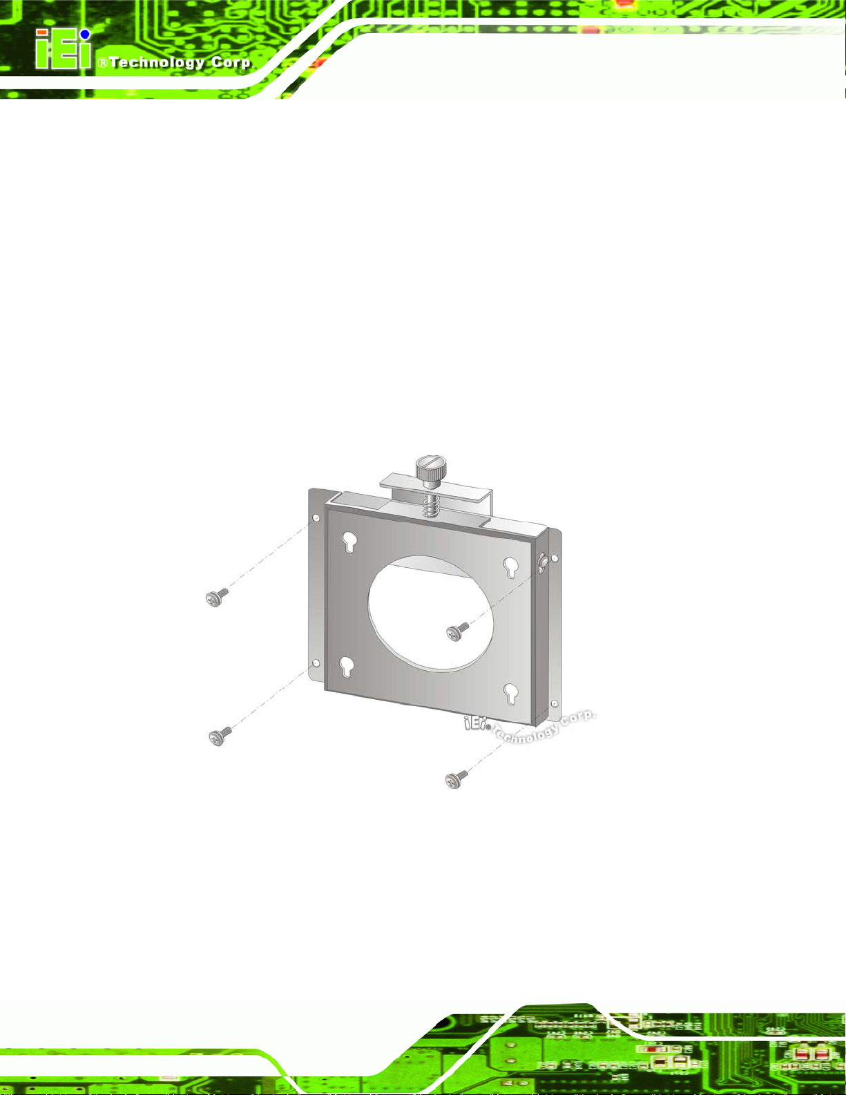
4.8.1 Wall Mounting
To mount the flat bezel panel PC onto the wall, please follow the steps below.
Step 1: Select the location on the wall for the wall-mounting bracket.
Step 2: Carefully mark the locations of the four screw holes in the bracket on the wall.
Step 3: Drill four pilot holes at the marked locations on the wall for the bracket retention
screws.
Step 4: Align the wall-mounting bracket screw holes with the pilot holes.
Step 5: Secure the mounting-bracket to the wall by inserting the retention screws into
AFL2-12A-HM65 Series Panel PC
the four pilot holes and tightening them (
Figure 4-7).
Figure 4-7: Wall-mounting Bracket
Page 34
Page 49
AFL2-12A-HM65 Series Panel PC
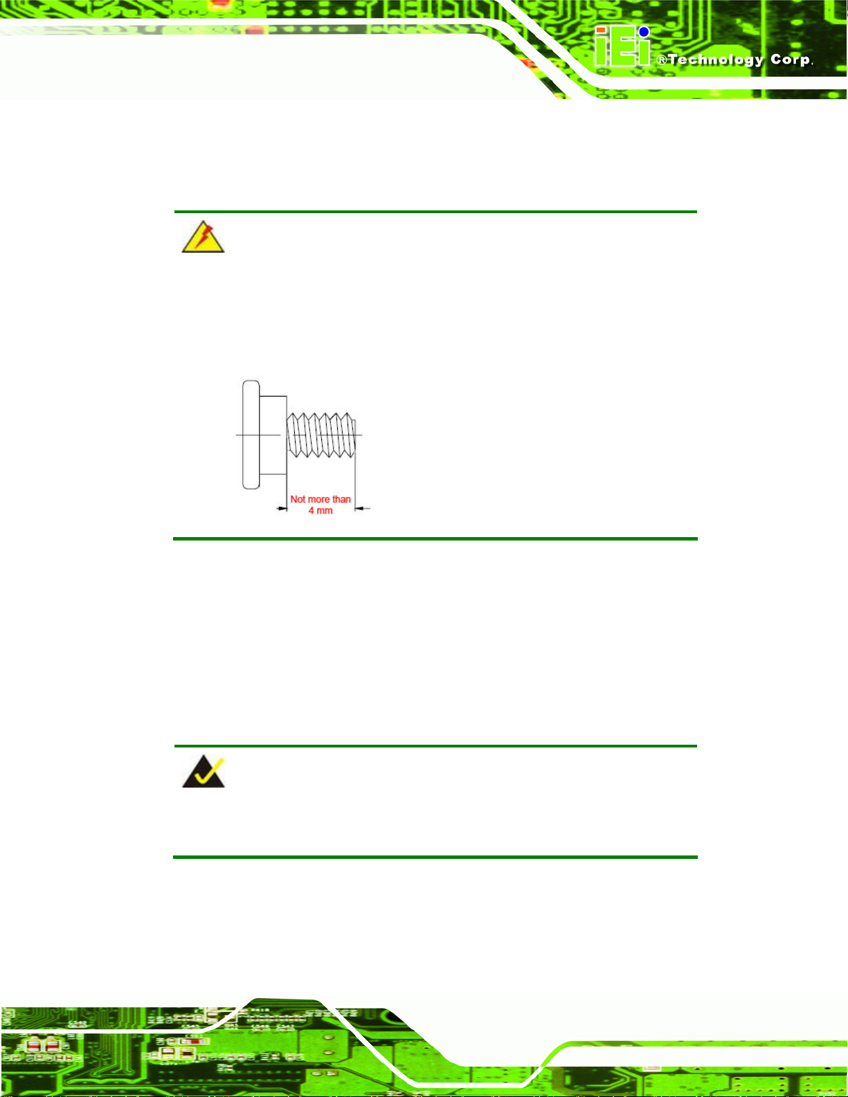
Step 6: Insert the four monitor mounting screws provided in the wall mount kit into the
four screw holes on the real panel of the flat bezel panel PC and tighten until the
screw shank is secured against the rear panel (
Figure 4-8).
WARNING:
Please use the M4 screws provided in the wall mount kit for the rear panel.
If the screw is missing, the thread depth of the replacement screw should
be not more than 4 mm.
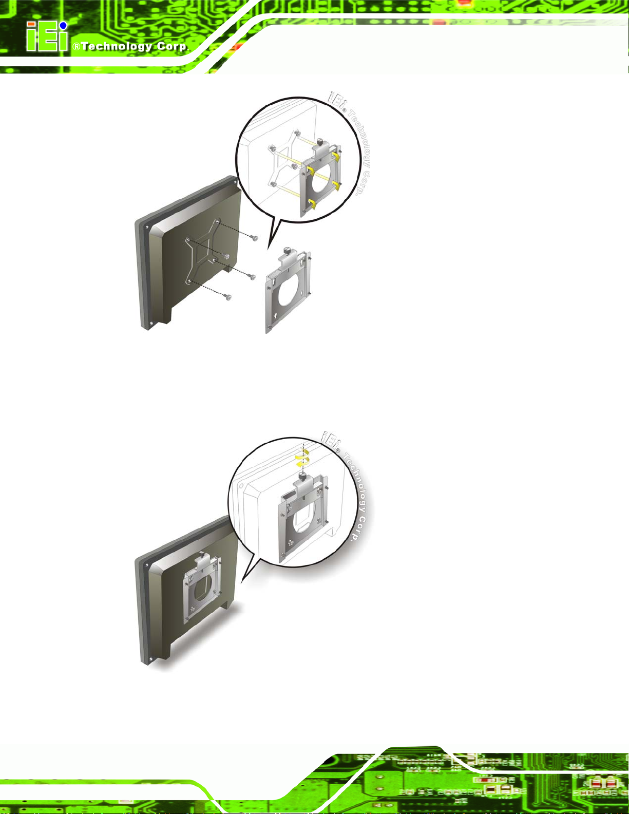
Step 7: Align the mounting screws on the monitor rear panel with the mounting holes on
the bracket.
Step 8: Carefully insert the screws through the holes and gently pull the monitor
downwards until the monitor rests securely in the slotted holes (
Ensure that all four of the mounting screws fit snuggly into their respective
slotted holes.
Figure 4-8).
NOTE:
In the diagram below the bracket is already installed on the wall.
Page 35
Page 50
AFL2-12A-HM65 Series Panel PC
Figure 4-8: Chassis Support Screws
Step 9: Secure the panel PC by fastening the retention screw of the wall-mounting
bracket. (
Figure 4-9).
Page 36
Figure 4-9: Secure the Panel PC
Page 51
AFL2-12A-HM65 Series Panel PC
4.8.2 Stand Mounting
To mount the AFL2-12A-HM65 using the stand mounting kit, please follow the steps
below.
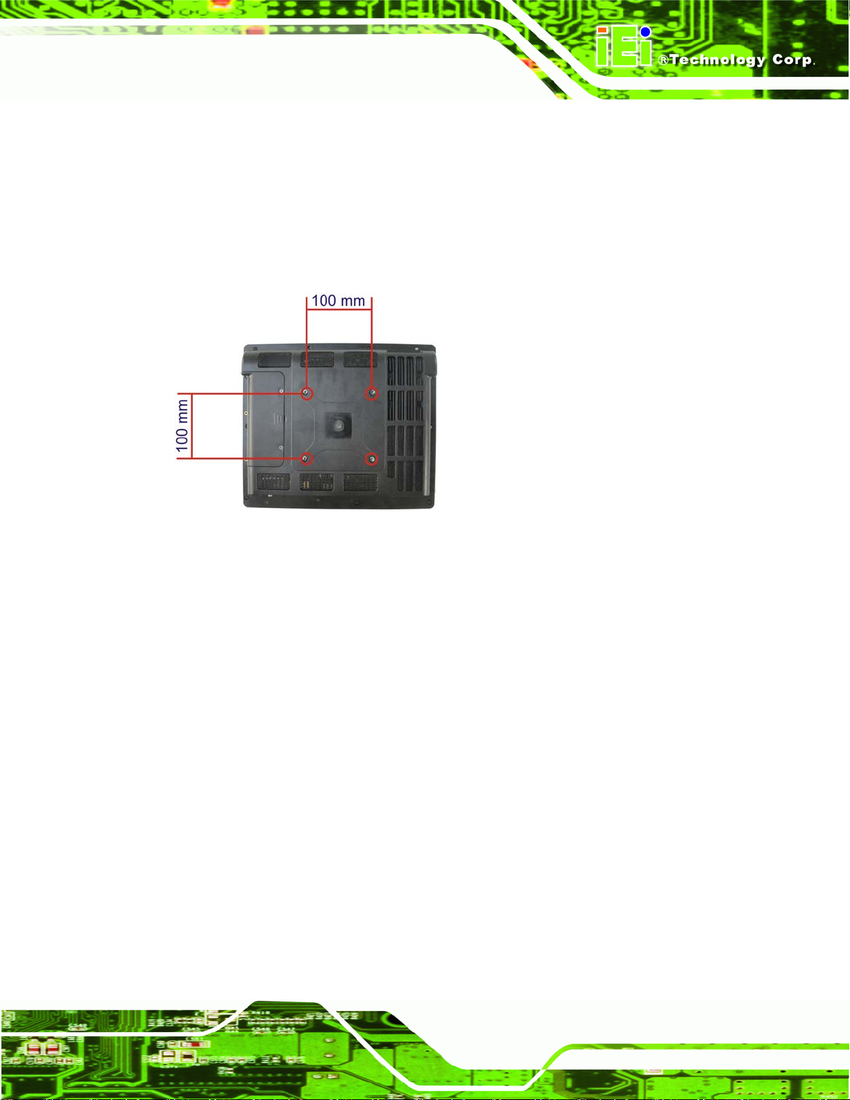
Step 1: Locate the screw holes on the rear of the AFL2-12A-HM65. This is where the
bracket will be attached. (
Figure 4-10)
Figure 4-10: Mounting screw location
Step 2: Align the bracket with the screw holes.
Step 3: To secure the bracket to the AFL2-12A-HM65, insert the retention screws into
the screw holes and tighten them.
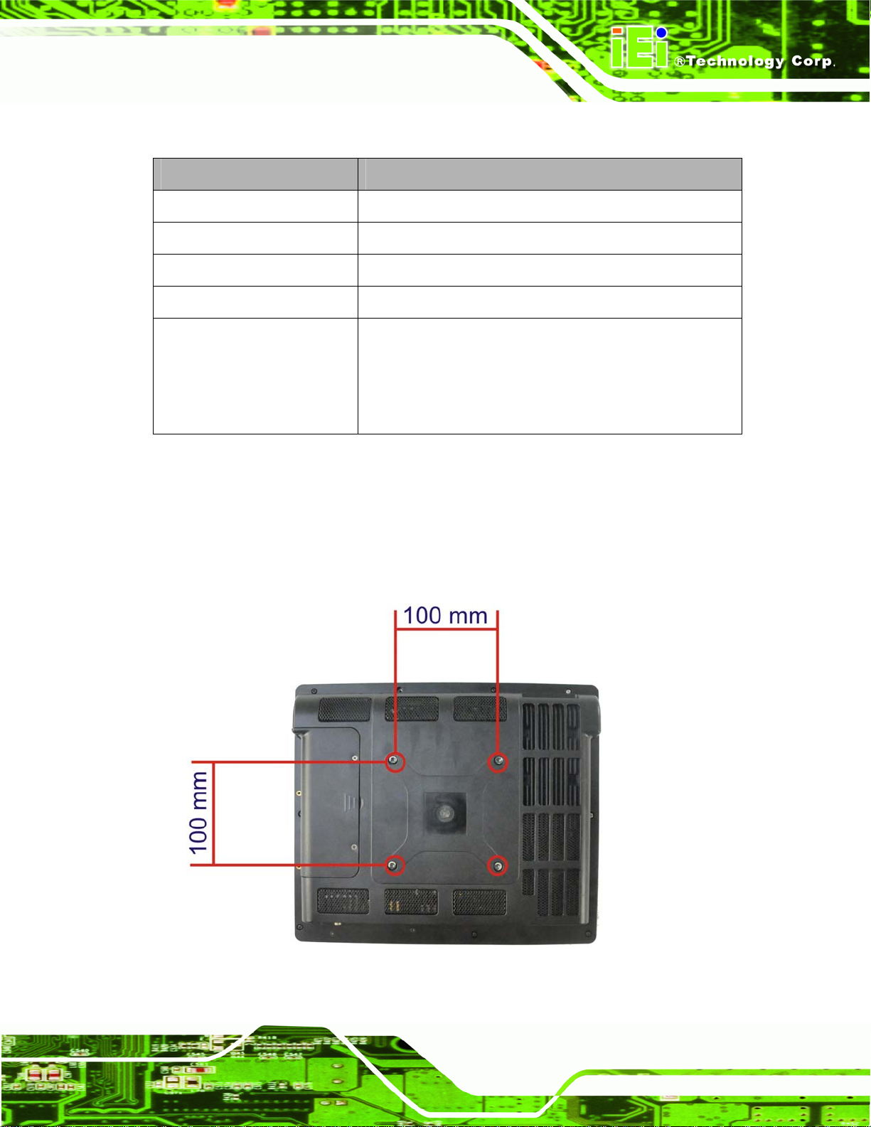
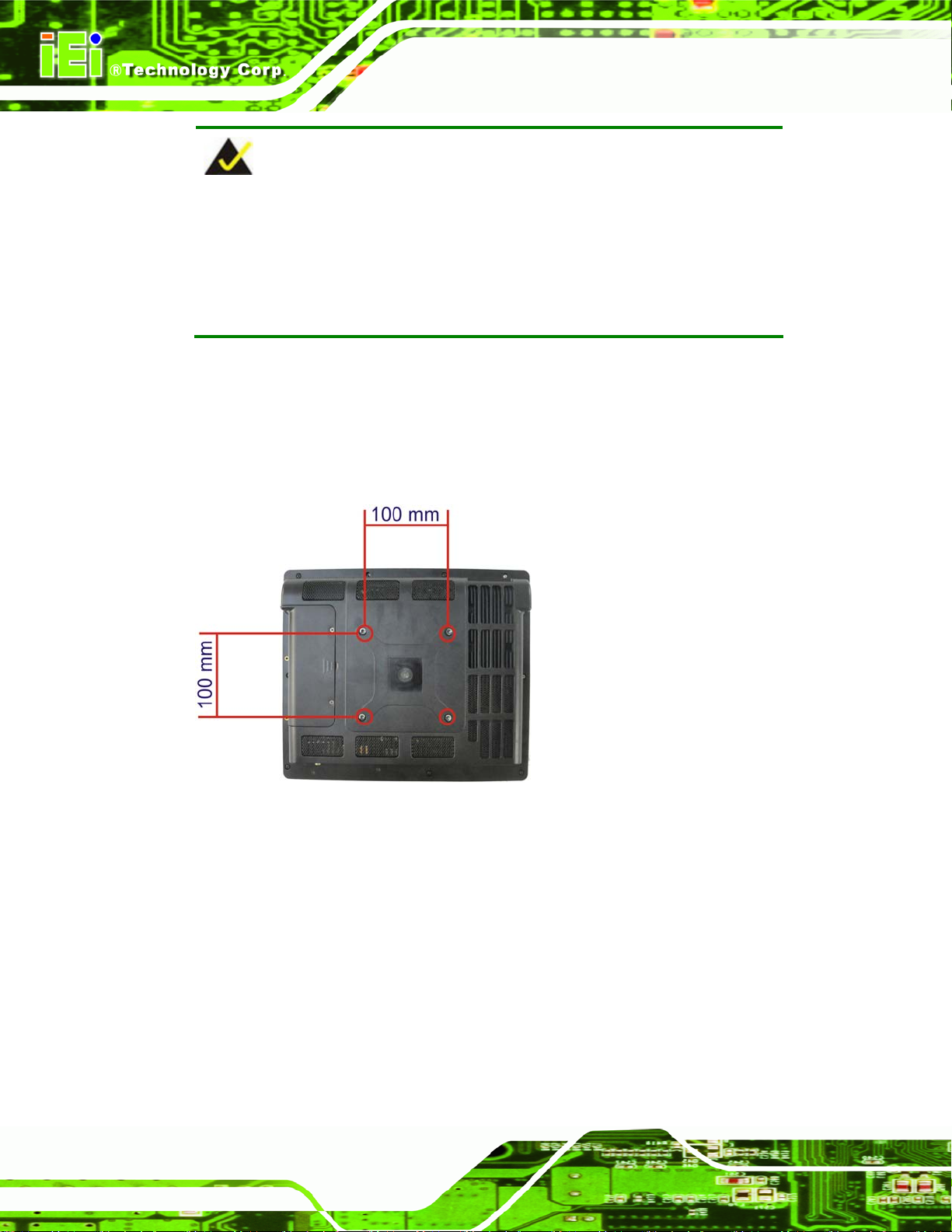
4.8.3 Arm Mounting
The AFL2-12A-HM65 is VESA (Video Electronics Standards Association) compliant and
can be mounted on an arm with a 100mm interface pad. To mount the AFL2-12A-HM65
on an arm, please follow the steps below.
Step 1: The arm is a separately purchased item. Please correctly mount the arm onto
the surface it uses as a base. To do this, refer to the installation documentation
that came with the mounting arm.
Page 37
Page 52
AFL2-12A-HM65 Series Panel PC
NOTE:
When purchasing the arm please ensure that it is VESA compliant and that
the arm has a 75 mm or 100 mm interface pad. If the mounting arm is not
VESA compliant it cannot be used to support the AFL2-12A-HM65 flat
bezel panel PC.
Step 2: Once the mounting arm has been firmly attached to the surfa ce, lif t the flat bezel
panel PC onto the interface pad of the mounting arm.
Step 3: Align the retention screw holes on the mounting arm interface with those in the
flat bezel panel PC (
Figure 4-11).
Figure 4-11: Arm Mounting Retention Screw Holes
Step 4: Secure the flat bezel panel PC to the interface pad by inserting four retention
screws through the bottom of the mounting arm interface pad and into the flat
bezel panel PC. Step 0:
4.8.4 Cabinet and Rack Installation
The AFL2-12A-HM65 flat bezel panel PC can be installed into a cabinet or rack. The
installation procedures are similar to the panel mounting installation. To do this, please
follow the steps below:
Page 38
Page 53
AFL2-12A-HM65 Series Panel PC
NOTE:
When purchasing the cabinet/rack installation bracket, make sure it is
compatible with both the AFL2-12A-HM65 flat bezel panel PC and the
rack/cabinet into which the AFL2-12A-HM65 is installed.
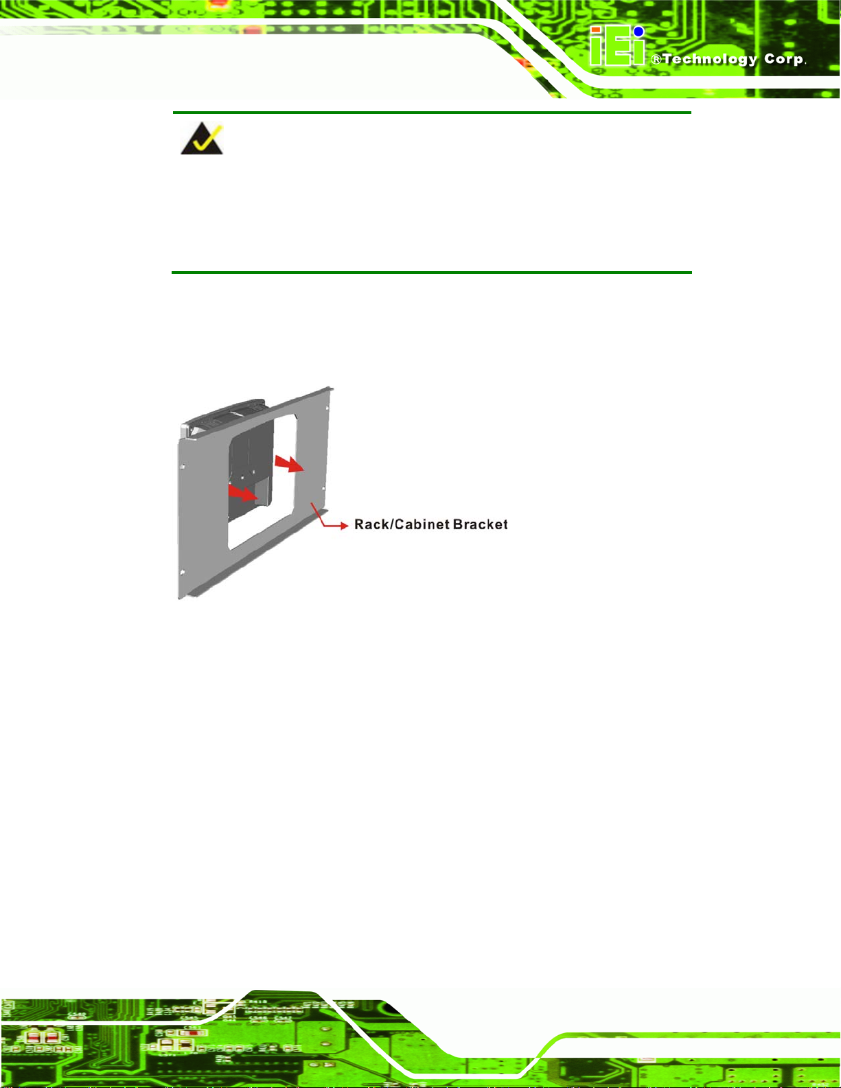
Step 1: Slide the rear chassis of the AFL2-12A-HM65 flat bezel panel PC through the
rack/cabinet bracket until the aluminum frame is flush against the front of the
bracket (
Figure 4-12).
Figure 4-12: The Rack/Cabinet Bracket
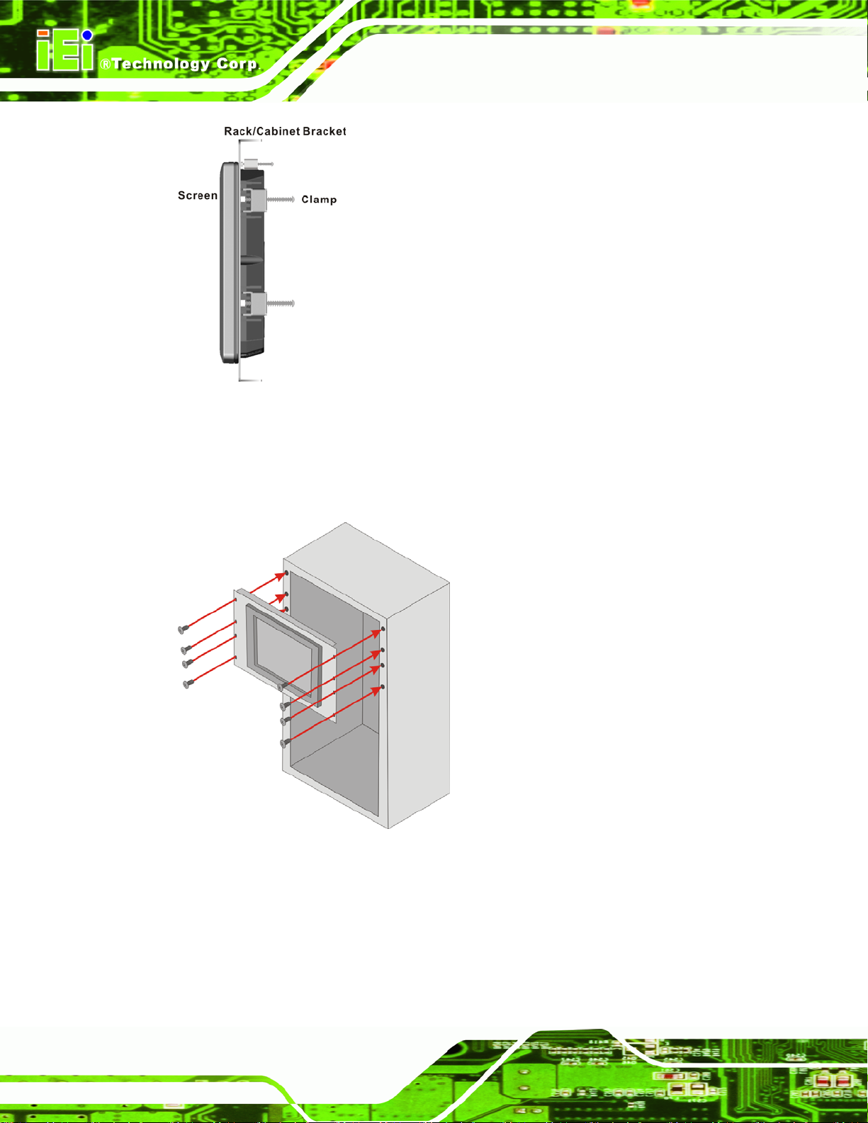
Step 2: Insert the rack mounting clamps into the pre-formed holes along the edges of
the flat bezel panel PC, behind the ABS/PC plastic frame. There are a total of 6
rack mounting clamps.
Step 3: Tighten the screws that pass through the rack mounting clamps until the plastic
caps at the front of all the screws are firmly secured to the bracket (
Figure 4-13).
Page 39
Page 54
AFL2-12A-HM65 Series Panel PC
Figure 4-13: Secure the Rack/Cabinet Bracket
Step 4: Slide the flat bezel panel PC with the attached rack/cabinet bracket into a rack or
cabinet (
Figure 4-14).
Page 40
Figure 4-14: Install into a Rack/Cabinet
Step 5: Once the flat bezel panel PC with the attached rack/cabinet bracket has been
properly inserted into the rack or cabinet, secure the front of the rack/cabinet
bracket to the front of the rack or cabinet (
Figure 4-14).
Page 55
AFL2-12A-HM65 Series Panel PC
4.9 Bottom Panel Connectors
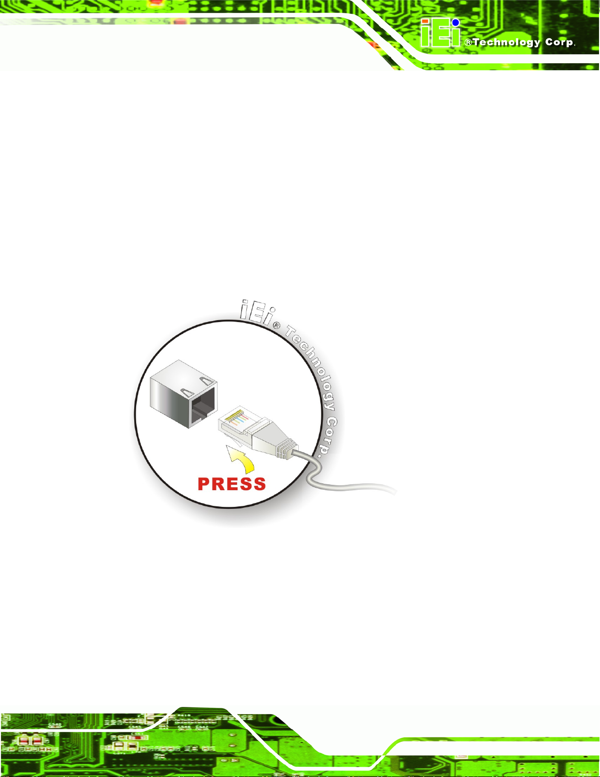
4.9.1 LAN Connection
There is one external RJ-45 LAN connector. The RJ-45 connector enables connection to
an external network. To connect a LAN cable with an RJ-45 connector, please follow the
instructions below.
Step 1: Locate the RJ-45 connector on the bottom panel of the AFL2-12A-HM65.
Step 2: Align the connector. Alig n the RJ-45 connector on the LAN cable with the
RJ-45 connectors on the bottom panel of the AFL2-12A-HM65. See
4-15.
Figure 4-15: LAN Connection
Figure
Step 3: Insert the LAN cable RJ-45 connector. Once aligned, gently insert the LAN
cable RJ-45 connector into the onboard RJ-45 connector. Step 0:
4.9.2 Serial Device Connection
The AFL2-12A-HM65 has one male DB-9 port connector and one RJ-45 serial port
connector on the I/O panel for serial device connection.
Page 41
Page 56
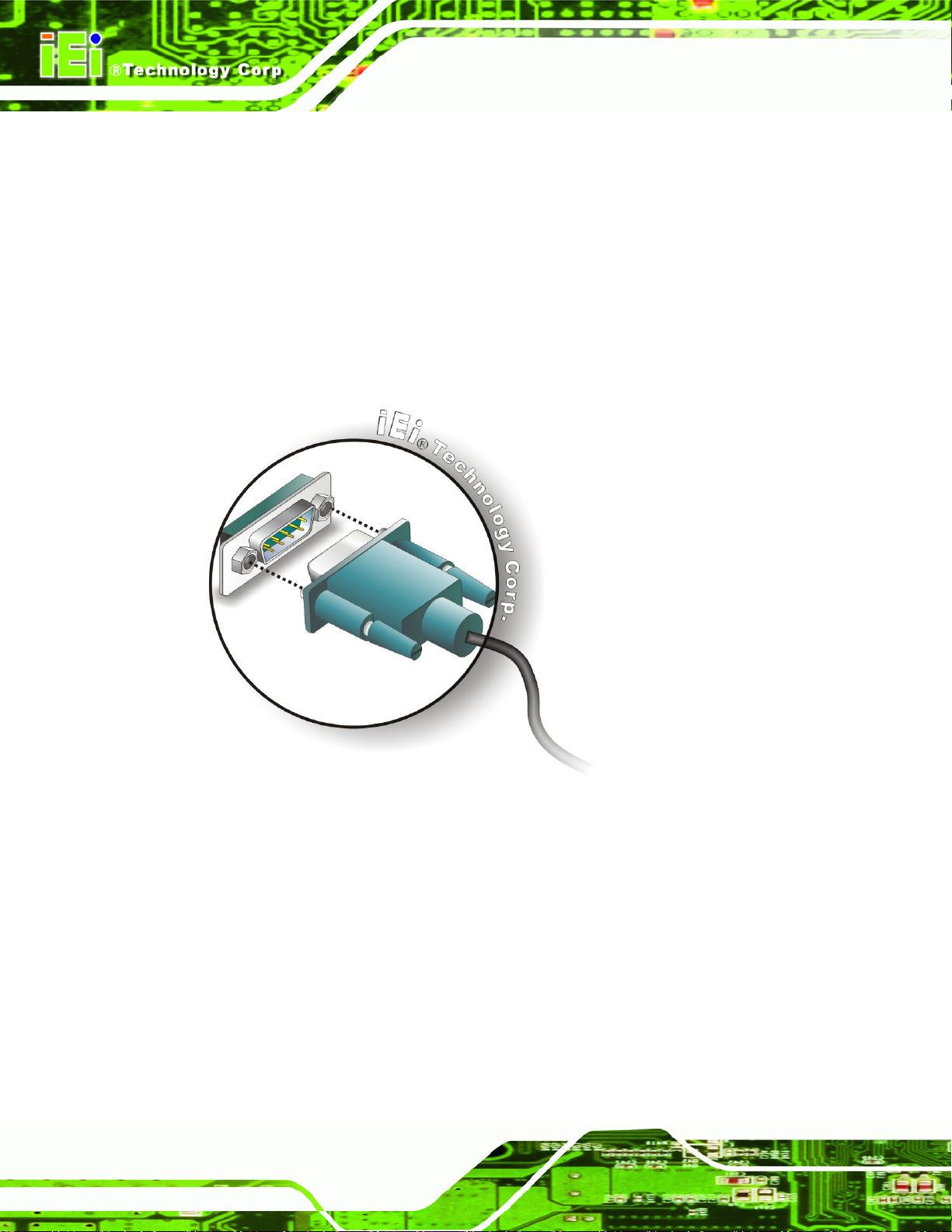
4.9.2.1 DB-9 Serial Port Connection
Follow the steps below to connect a serial device to the DB-9 connector of the
AFL2-12A-HM65 panel PC.
Step 1: Locate the DB-9 connector. The location of the DB-9 connector is shown in
Chapter 2.
Step 2: Insert the serial connector. Insert the DB-9 connector of a serial device into
AFL2-12A-HM65 Series Panel PC
the DB-9 connector on the bottom panel. See
Figure 4-16.
Figure 4-16: DB-9 Serial Port Connector
Step 3: Secure the connector. Secure the serial device connector to the external
interface by tightening the two retention screws on either side of the connector.
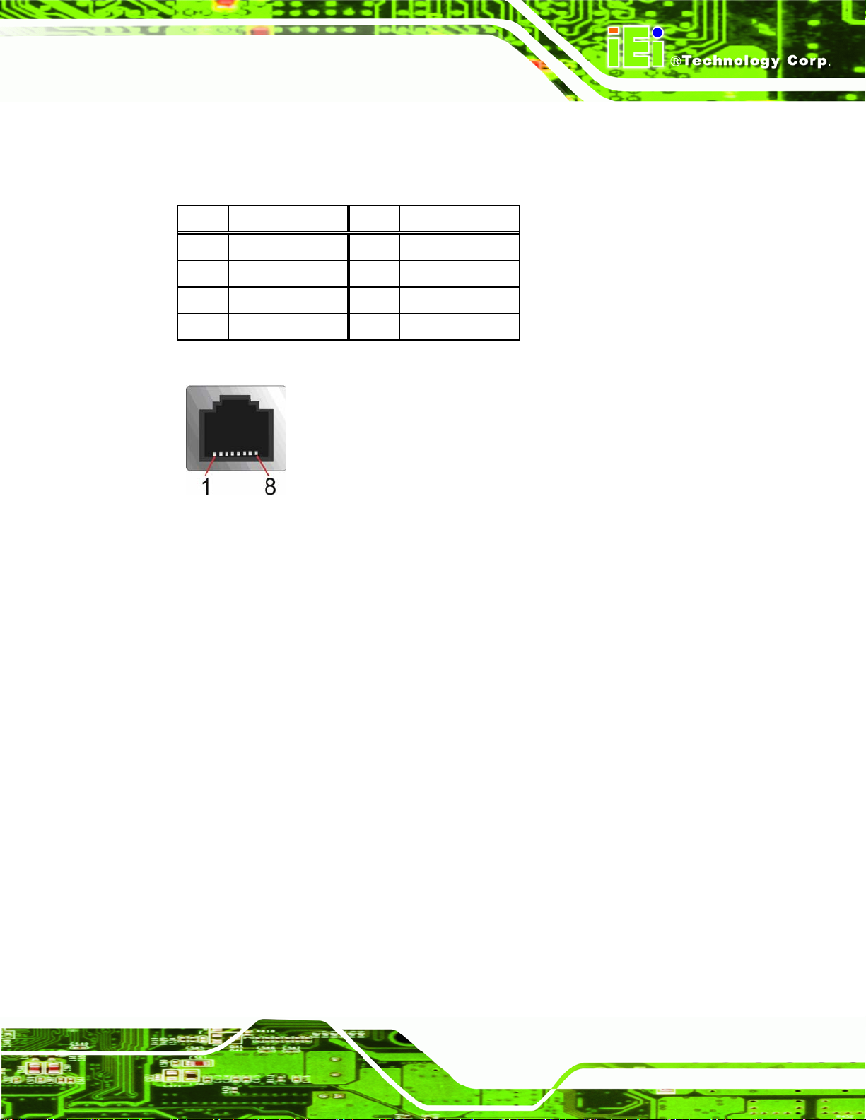
4.9.2.2 RJ-45 Serial Port Connection
CN Label: COM3
RJ-45
See Figure 4-17
Page 42
CN Type:
CN Location:
Step 0:
Page 57
AFL2-12A-HM65 Series Panel PC
See
CN Pinouts:
A 10/100/1000 Mb/s connection can be made to a Local Area Network.
Pin Description Pin Description
1 NDCD3 5 NTXD3
2 NDSR3 6 NCTS3
3 NRXD3 7 NDTR3
4 NRTS3 8 NRI3
Table 4-1
Table 4-1: Ethernet Connector Pinouts
Figure 4-17: Ethernet Connector
Follow the steps below to connect a serial device to the RJ-45 serial port connector of the
AFL2-12A-HM65 panel PC.
Step 1: Locate the RJ-45 serial port. The location of the RJ-45 serial port is shown in
Chapter 2.
Step 2: Connect the RJ-45 to COM port cable to the panel PC. Insert the RJ-45
connector end of cable into the RJ-45 serial port. See
Figure 4-18.
Step 3: Connect the serial device. Connect a serial device to the DB-9 connector end
of the cable. See
Figure 4-18.
Page 43
Page 58

AFL2-12A-HM65 Series Panel PC
Figure 4-18: RJ-45 Serial Port Connector
Step 4: Secure the connector. Secure the serial device connector to the external
interface by tightening the two retention screws on either side of the connector.
4.9.3 RS-422/485 Serial Port Connection
CN Label: COM6
CN Type:
CN Location:
CN Pinouts:
A RS-422/485 serial port device can be connected to the RS-422/485 serial port on the
bottom panel. The pinouts of the RS-422/485 serial port are shown below.
4-pin connector
Figure 4-19
See
Table 4-2 and Figure 4-20
See
Figure 4-19: RS-422/485 Serial Port
Step 0:
Page 44
Page 59

AFL2-12A-HM65 Series Panel PC
Pin RS-422 RS-485
1 RX+
2 RX-
3 TX+ DATA+
4 TX- DATA-
Table 4-2: RS-422/485 Serial Port Pinouts
To install the RS-422/485 devices, follow the steps below.
Step 1: Locate the RS-422/RS485 connector. The location of the RS-422/RS-485
connector is shown in
Figure 1-6.
Step 1: Connect the RS-422/485 connector to the RS-422/485 cable. The
RS-422/485 cable can be found in the packing list and is shown in
Figure 4-20.
Figure 4-20: RS-422/485 Cable
Step 2: Insert the serial connector. Insert the DB-9 connector of a serial device into
the DB-9 connector on the RS-422/485 cable.
Step 3: Secure the connector. Secure the serial device connector to the external
interface by tightening the two retention screws on either side of the connector.
The DB-9 connector pinouts are listed below. Step 0:
Figure 4-21: DB-9 Connector
Pin RS-422 RS-485
1 TX- DATA-
Page 45
Page 60

Pin RS-422 RS-485
2 TX+ DATA+
3 RX+
4 RX-
Table 4-3: DB-9 Connector Pinouts
4.9.4 USB Device Connection
NOTE:
User must install the USB 3.0 driver before connecting a USB device to
the system or else the system may not recognize the connected
device.
AFL2-12A-HM65 Series Panel PC
There are two USB 2.0 connectors and two USB 3.0 connectors. All connectors are
located on the bottom panel of the AFL2-12A-HM65. To connect a USB device, please
follow the instructions below.
Step 1: Locate the USB connectors. The locations of the USB connectors are shown
in Chapter 2.
Step 2: Align the connectors. Align the USB device connector with one of the
connectors on the bottom panel. See
Figure 4-22.
Page 46
Page 61

AFL2-12A-HM65 Series Panel PC
Figure 4-22: USB Device Connection
Step 3: Insert the device connector. Once aligned, gently insert the USB device
connector into the onboard connector. Step 0:
4.9.5 HDMI Device Connection
The HDMI connector transmits a digital signal to compatible HDMI display devices such
as a TV or computer screen. To connect the HDMI cable to the AFL2-12A-HM65, follow
the steps below.
Step 1: Locate the HDMI connector. The location is shown in Chapter 1.
Step 2: Align the connector. Alig n the HDMI connector with the HDMI port. Make sure
the orientation of the connector is correct.
Page 47
Page 62

Figure 4-23: HDMI Connection
Step 3: Insert the HDMI connector. Gently insert the HDMI connector. The connector
AFL2-12A-HM65 Series Panel PC
should engage with a gentle push. If the connector does not insert easily, check
again that the connector is aligned correctly, and that the connector is being
inserted with the right way up. Step 0:
Page 48
Page 63

AFL2-12A-HM65 Series Panel PC
Chapter
5
5 System Maintenance
Page 49
Page 64
AFL2-12A-HM65 Series Panel PC
5.1 System Maintenance Introduction
If the components of the AFL2-12A-HM65 fail they must be replaced. Components that
can be replaced include:
SO-DIMM module
WLAN Module
Please contact the system reseller or vendor to purchase the replacement parts. Back
cover removal instructions for the AFL2-12A-HM65 are described below.
5.2 Anti-static Precautions
WARNING:
Failure to take ESD precautions during the maintenance of the
AFL2-12A-HM65 may result in permanent damage to the
AFL2-12A-HM65 and severe injury to the user.
Electrostatic discharge (ESD) can cause serious damage to electronic components,
including the AFL2-12A-HM65. Dry climates are especially susceptible to ESD. It is
therefore critical that whenever the AFL2-12A-HM65 is accessed internally, or any other
electrical component is handled, the following anti-static precautions are strictly adhered
to.
Wear an anti-static wristband: - Wearing a simple anti-static wristband can
help to prevent ESD from damaging the board.
Self-grounding: - Before handling the board touch any grounded conducting
material. During the time the board is handled, frequently touch any
conducting materials that are connected to the ground.
Use an anti-static pad: - When configuring the AFL2-12A-HM65, place it on
Page 50
an antic-static pad. This reduces the possibility of ESD damaging the
AFL2-12A-HM65.
Only handle the edges of the PCB: - When handling the PCB, hold the PCB
by the edges.
Page 65
AFL2-12A-HM65 Series Panel PC
5.3 Turn off the Power
WARNING:
Failing to turn off the system before opening it can cause permanent
damage to the system and serious or fatal injury to the user.
Before any maintenance procedures are carried out on the system, make sure the system
is turned off.
To power off the system, follow the steps below:
Step 1: Locate the Function and Brightness Up function keys. See Section
Step 2: Hold down the Function and Brightness Up buttons for six seconds to power off
the system. Step 0:
5.4 Opening the System
5.4.1 Removing the Back Cover
WARNING:
Over-tightening back cover screws will crack the plastic frame.
Maximum torque for cover screws is 5 kg-cm (0.36 lb-ft/0.49 Nm).
To access the AFL2-12A-HM65 internally the back cover must be removed. To remove the
back cover, please follow th e steps below.
1.2.1.1.
Step 1: Follow all anti-static procedures. See Section
Step 2: Turn off the power. See Section
5.3.
5.2.
Page 51
Page 66
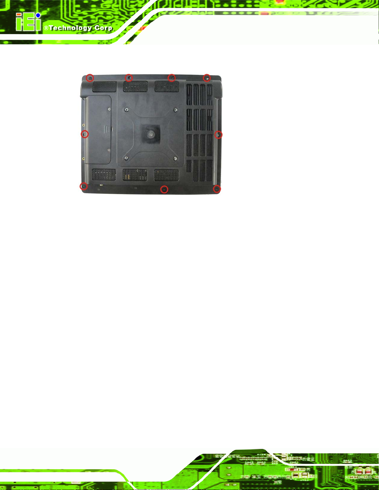
Step 3: Remove a total of nine (9) retention screws from the back cover (Figure 5-1).
AFL2-12A-HM65 Series Panel PC
Figure 5-1: Back Cover Retention Screws
Step 4: Carefully separate the back cover from the chassis and lift the cover clear of the
device Step 0:
5.4.2 Removing the Internal Aluminum Cover
To remove the internal aluminum cover, follow the steps below.
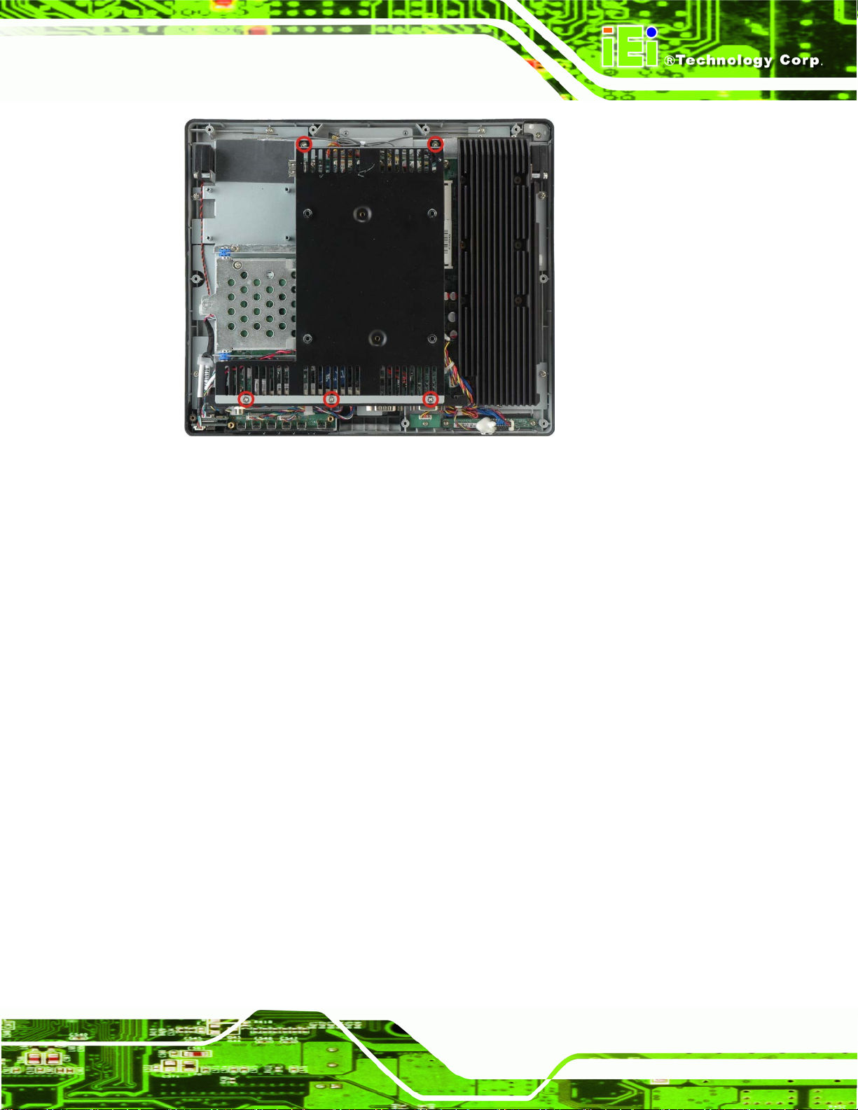
Step 1: Remove the six (6) retention screws securing the internal aluminum cover to the
chassis (Figure 5-2).
Page 52
Page 67
AFL2-12A-HM65 Series Panel PC
Figure 5-2: Internal Cover Retention Screws
Step 2: Lift the aluminum cover off the AFL2-12A-HM65. Step 0:
5.5 Replacing Components
5.5.1 Memory Module Replacement
The flat bezel panel PC is preinstalled with a 1.0 GB DDR3 memory module. If the
memory module fails, follow the instructions below to replace the memory module.
Step 1: Follow all anti-static procedures. See Section
Step 2: Turn off the power. See Section
Step 3: Remove the back cover. S ee Section
Step 4: Remove the internal aluminum back cover. See Section
Step 5: Locate the DDR3 SO-DIMM on the motherboard.
5.2.
5.3.
5.4.1 above.
5.4.2 above.
Step 6: Remove the DDR3 memory module by pulling both the spring retainer clips
outward from the socket.
Page 53
Page 68
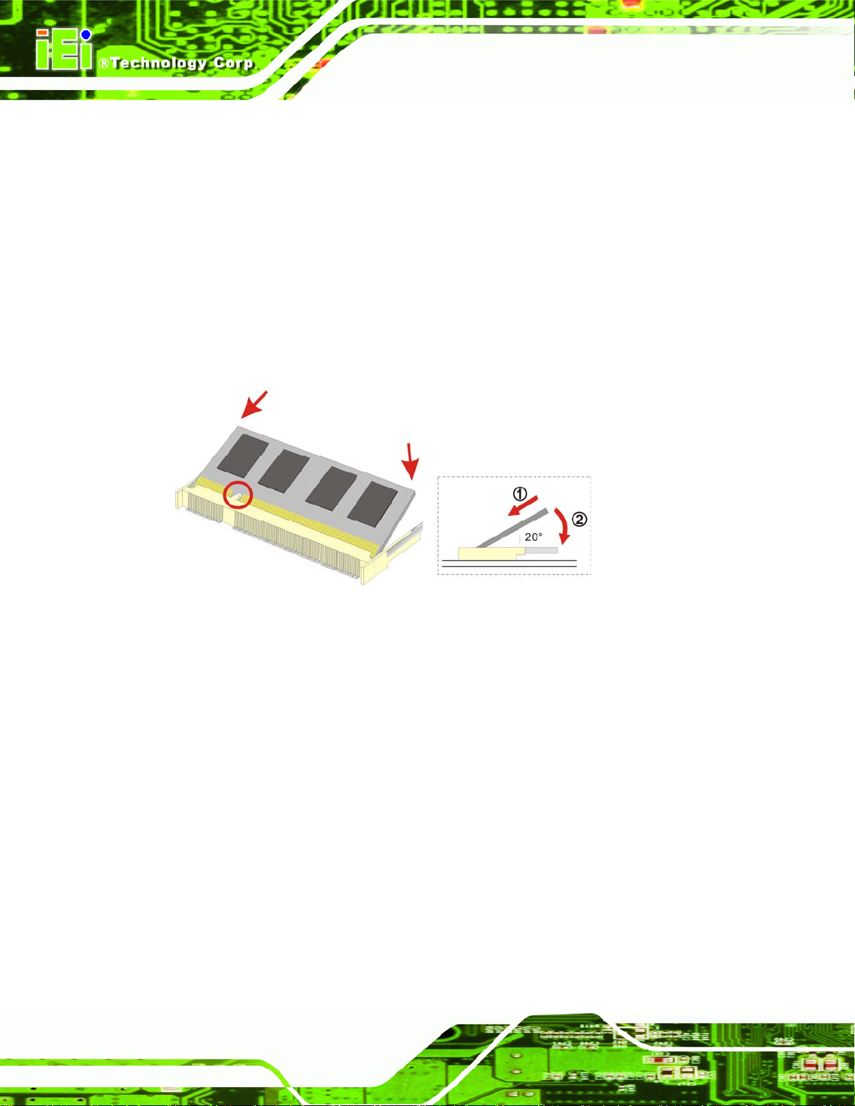
Step 7: Grasp the DDR3 memory module by the edges and carefully pull it out of the
socket.
Step 8: Install the new DDR3 memory module by pushing it into the socket at an angle
Figure 5-3).
(
Step 9: Gently pull the spring retainer clips of the SO-DIMM socket out and push the
AFL2-12A-HM65 Series Panel PC
rear of the DDR memory module down (
Step 10: Release the spring retainer clips on the SO-DIMM socket. They clip into place
and secure the DDR memory module in the socket.
Figure 5-3).
Figure 5-3: DDR SO-DIMM Module Installation
Step 11: Replace the internal aluminum cover and se cure it to the chassis using six (6)
retention screws.
Step 12: Replace the back cover and secure it using ni ne (9) previously removed
retention screws. Step 0:
5.5.2 WLAN Card Replacement
The AFL2-12A-HM65 has one WLAN card slot. To replace the WLAN card, follow the
instructions below.
Step 1: Follow all anti-static procedures. See Section
Step 2: Turn off the power. See Section
Step 3: Remove the back cover. S ee Section
Page 54
5.2.
5.3.
5.4.1.
Page 69
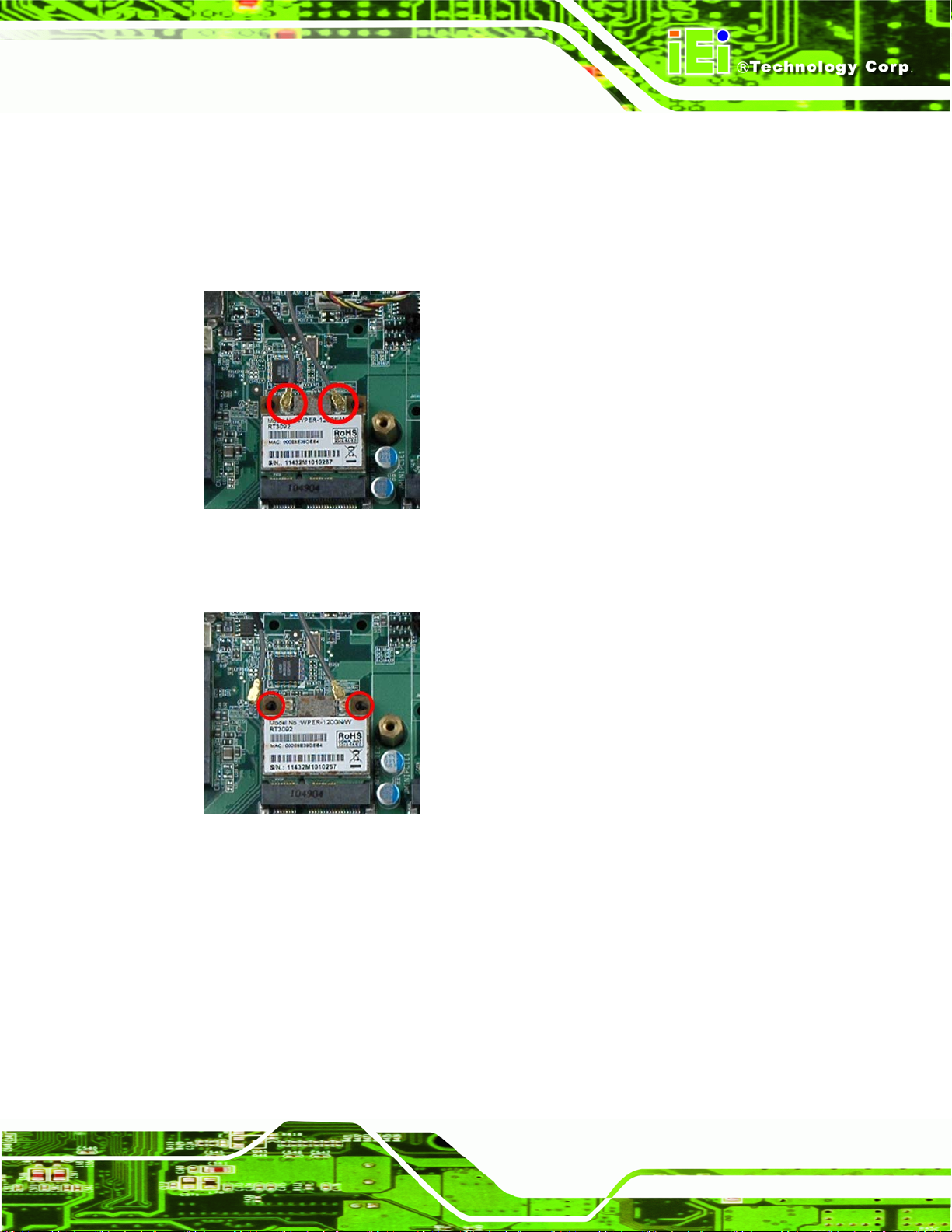
AFL2-12A-HM65 Series Panel PC
Step 4: Remove the internal aluminum back cover. See Section 5.4.2.
Step 5: Locate the WLAN card.
Step 6: Disconnect the main and auxiliary antennas on the WLAN module
Figureٛ 5-4).
(
Figure
Step 7: Push the two spring clips in to release the WLAN card.
Figure
ٛ 5-4: Removing the Antennas
ٛ 5-5: Releasing the WLAN Card
Page 55
Page 70
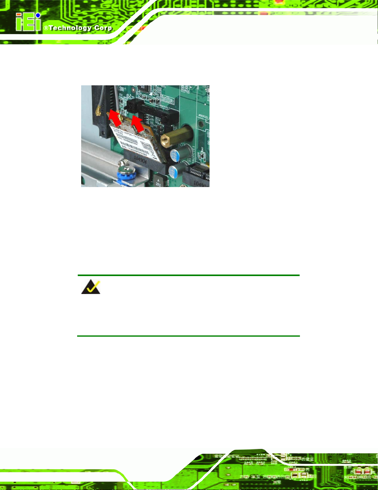
Step 8: Grasp the WLAN card by the edges and carefully pull it out of the socket
Figureٛ 5-6).
(
AFL2-12A-HM65 Series Panel PC
Figure
Step 9: Install a new WLAN card by inserting the card into the slot at an angle
Step 10: Push the WLAN card down until the spring retainer clips lock into place.
Step 11: Connect the main (1) and auxiliary (2) antennas. The main antenna is indicated
ٛ 5-6: Removing the WLAN card
with a strip of black electrical tape. See
Figureٛ 5-7.
NOTE:
To ensure the WLAN module functions correctly, please make sure the
WLAN antennas are attached in the proper configuration.
Page 56
Page 71
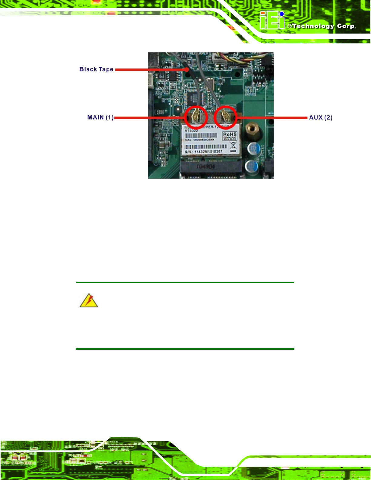
AFL2-12A-HM65 Series Panel PC
Figureٛ 5-7: Attaching the Antennas
Step 12: Replace the internal aluminum cover and se cure it to the chassis using six (6)
retention screws.
Step 13: Replace the back cover and secure it using ni ne (9) previously removed
retention screws. Step 0:
5.6 Reinstalling the Covers
WARNING:
Failing to reinstall the covers may result in permanent damage to the
system. Please make sure all coverings are properly installed.
When maintenance procedures are complete, please make sure all the covers are
replaced, including the following:
Aluminum internal cover
Plastic back cover
Plastic HDD cover
Page 57
Page 72

AFL2-12A-HM65 Series Panel PC
Chapter
6
6 AMI BIOS Setup
Page 58
Page 73
AFL2-12A-HM65 Series Panel PC
6.1 Introduction
A licensed copy of the BIOS is preprogrammed into the ROM BIOS. The BIOS setup
program allows users to modify the basic system configuration. This chapter describes
how to access the BIOS setup program and the configuration options that may be
changed.
6.1.1 Starting Setup
The UEFI BIOS is activated when the computer is turned on. The setup program can be
activated in one of two ways.
1. Press the
2. Press the
message appears on the screen. 0.
If the message disappears before the F2
try again.
F2 or DEL key as soon as the system is turned on or
F2 or DEL key when the “Press F2 to enter SETUP”
OR DEL key is pressed, restart the computer and
6.1.2 Using Setup
Use the arrow keys to highlight items, press ENTER to select, use the PageUp and
PageDown keys to change entries, press F1 for help and press E
keys are shown in the following table.
Key Function
Up arrow Move to the item above
Down arrow Move to the item below
Left arrow Move to the item on the left hand side
SC to quit. Navigation
Right arrow Move to the item on the right hand side
+ Increase the numeric value or make ch anges
- Decrease the numeric value or make changes
Page Up key Move to the next page
Page Dn key Move to the previous page
Page 59
Page 74

Esc key Main Menu – Quit and do n ot save ch anges into CMOS
F1 key General help, only for St atus Page Setup Menu and Option
F2 key Load previous values
F3 key Load optimized defaults
F4 key Save changes and Exit BIOS
Table 6-1: BIOS Navigation Keys
6.1.3 Getting Help
When F1 is pressed a small help window describing the appropriate keys to use and the
AFL2-12A-HM65 Series Panel PC
Status Page Setup Menu and Option Page Setup Menu -Exit current page and return to Main Menu
Page Setup Menu
possible selections for the highlighted item appears. To exit the Help Window press E
the F1 key again.
6.1.4 Unable to Reboot After Configuration Changes
If the computer cannot boot after changes to the system configuration are made, CMOS
defaults. Use the jumper described in Chapter 4.
6.1.5 BIOS Menu Bar
The menu bar on top of the BIOS screen has the following main items:
Main Changes the basic system configuration.
Advanced Changes the advanced system settings.
Chipset Changes the chipset settings
Boot Changes the system boot configuration.
Security Sets User and Supervisor Passwords.
Save & Exit Selects exit options and loads default settings
SC or
Page 60
The following sections completely describe the configuration options found in the menu
items at the top of the BIOS screen and listed above.
Page 75

AFL2-12A-HM65 Series Panel PC
6.2 Main
The Main BIOS menu (6BIOS Menu 1) appears when the BIOS Setup program is entered.
The Main menu gives an overview of the basic system information.
Aptio Setup Utility – Copyright (C) 2010 American Megatrends, Inc.
Main Advanced Chipset Boot Security Save & Exit
BIOS Information
BIOS Vendor American Megatrends
Core Version 4.6.4.0 0.15
Compliency UEFI 2.1
Project Version SC99AR14.ROM
Build Date and Time 11/01/2011 16:55:39
iWDD Vendor ICP
iWDD Version SC99ER13.bin
System Date [Mon 01/10/2011]
System Time [10:55:27]
Access Level Administrator
Version 2.10.1208. Copyright (C) 2010 American Megatrends, Inc.
Set the Date. Use Tab to
switch between Data
elements.
----------------------
ÅÆ
: Select Screen
↑ ↓: Select Item
Enter Select
+/-: Change Opt.
F1: General Help
F2: Previous Values
F3: Optimized Defaults
F4: Save & Exit
ESC: Exit
BIOS Menu 1: Main
Î System Overview
The System Overvie w lists a brief summary of different system components. Th e fields in
System Overview cannot be changed. The items shown in the system overview include:
BIOS Vendor: Installed BIOS vendor
Core Version: Current BIOS version
Compliency: Current BIOS compliant version
Project Version: The board version
Build Date and Time: Date the current BIOS version was made
Access Level: User access level
The System Overview field also has two user configurable fields:
Page 61
Page 76

Î System Date [xx/xx/xx]
Use the System Date option to set the system date. Manually enter the day, month and
year.
Î System Time [xx:xx:xx]
Use the System Time option to set the system time. Manually enter the hours, minutes
and seconds.
6.3 Advanced
Use the Advanced menu (6BIOS Menu 2) to configure the CPU and peripheral devices
through the following sub-menus:
WARNING:
AFL2-12A-HM65 Series Panel PC
Setting the wrong values in the sections below may cause the system
to malfunction. Make sure that the settings made are compatible with
the hardware.
ACPI Settings
CPU Configuration
SATA Configuration
USB Configuration
Super IO Configuration
H/W Monitor
Serial Port Console Redirection
iEi Feature
Page 62
Page 77

S
AFL2-12A-HM65 Series Panel PC
Aptio Setup Utility – Copyright (C) 2010 American Megatrends, Inc.
Main Advanced Chipset Boot Security Save & Exit
> ACPI Settings
> CPU Configuration
> SATA Configuration
> USB Configuration
> Super IO Configuration
> H/M Monitor
> Serial Port Console Redirection
> iEi Feature
Version 2.10.1208. Copyright (C) 2010 American Megatrends, Inc.
BIOS Menu 2: Advanced
System ACPI Parameters.
----------------------
ÅÆ
↑ ↓: Select Item
Enter Select
+/-: Change Opt.
F1: General Help
F2: Previous Values
F3: Optimized Defaults
F4: Save & Exit
ESC: Exit
: Select Screen
6.3.1 ACPI Settings
The ACPI Settings menu (6BIOS Menu 3) configures the Advanced Configuration and
Power Interface (ACPI) options.
Aptio Setup Utility – Copyright (C) 2010 American Megatrends, Inc.
Advanced
ACPI Settings
ACPI Sleep State [S3 (Suspend to RAM)]
Version 2.10.1208. Copyright (C) 2010 American Megatrends, Inc.
elect the highest ACPI
sleep state the system
will enter, when the
SUSPEND button is
pressed.
----------------------
ÅÆ
: Select Screen
↑ ↓: Select Item
Enter Select
+/-: Change Opt.
F1: General Help
F2: Previous Values
F3: Optimized Defaults
F4: Save & Exit
ESC: Exit
BIOS Menu 3: ACPI Configuration
Page 63
Page 78

Î ACPI Sleep State [S3 (Suspend to RAM)]
Use the ACPI Sleep State option to specify the sleep state the system enters when it is
not being used.
AFL2-12A-HM65 Series Panel PC
Î
Suspend Disabled
Î
S1 (CPU Stop
Clock)
Î
S3 (Suspend to
RAM)
DEFAULT
Suspend function disabled.
The system enters S1 (POS) sleep state. The
system appears off. The CPU is stopped; RAM is
refreshed; the system is running in a low power
mode.
The caches are flushed and the CPU is powered
off. Power to the RAM is maintained. The
computer returns slower to a working state, but
more power is saved.
6.3.2 CPU Configuration
Use the CPU Configuration menu (BIOS Menu 4) to view detailed CPU specifications
and configure the CPU.
Page 64
Page 79

a
AFL2-12A-HM65 Series Panel PC
Aptio Setup Utility – Copyright (C) 2010 American Megatrends, Inc.
Advanced
CPU Configuration
Intel(R) Core(TM) i5-2510E CPU @ 2.50GHz
Processor Stepping 206a7
Microcode Revision 17
Max Processor Speed 2500 MHz
Min Processor Speed 800 MHz
Processor Speed 2500 MHz
Processor Cores 2
Intel HT Technology Supported
EMT64 Supported
Hyper-threading [Enabled]
Intel Virtualization Technology [Disabled]
Version 2.10.1208. Copyright (C) 2010 American Megatrends, Inc.
Enabled for Windows XP
nd Linux (OS optimized
for Hyper-Threading
Technology) and Disabled
for other OS (OS not
optimized for
Hyper-Threading
Technology). When
Disabled only one thread
per enabled core is
enabled.
----------------------
ÅÆ
: Select Screen
↑ ↓: Select Item
Enter Select
+/-: Change Opt.
F1: General Help
F2: Previous Values
F3: Optimized Defaults
F4: Save & Exit
ESC: Exit
BIOS Menu 4: CPU Configuration
The CPU Configuration menu (
Processor Stepping: Lists the CPU processing stepping
Microcode Revision: Lists the microcode revision
Max Processor Speed: Lists the Max CPU processing speed
Min Processor Speed: Lists the Min CPU processing speed
Processor Speed: Lists the CPU processing speed
Processor Cores: Lists the number of the processor cores
Intel HT Technology: Indicates if Intel HT Technology is supported by the
CPU.
EMT64: Indicates if EM64T is supported by the CPU.
Î Hyper Threading Function [Enabled]
Use the Hyper Threading function to enable or disable the CPU hyper threading function.
BIOS Menu 4) lists the following CPU details:
Page 65
Page 80
AFL2-12A-HM65 Series Panel PC
Î
Disabled
Î
Enabled DEFAULT
Î Intel® Virtualization Technology [Disabled]
Use the Intel® Virtualization Technology option to enable or disable virtualization on the
system. When combined with third party software, Intel Virtualization technology allows
several OSes to run on the same system at the same time.
Î
Disabled DEFAULT
Î
Enabled
Disables the use of hyper threading technology
Enables the use of hyper threading technology
Disables the use of Intel Virtualization technology
Enables the use of Intel Virtualization technology
6.3.3 SATA Configuration
Use the IDE Configuration menu (BIOS Menu 5) to change and/or set the configuration
of the SATA devices installed in the system.
Aptio Setup Utility – Copyright (C) 2010 American Megatrends, Inc.
Advanced
SATA Controller(s) [Enhanced]
SATA Mode Selection [IDE]
Serial ATA Port 0 Empty
Software Preserve Unknown
Serial ATA Port 1 WDC WD1600BEVT (160.0
Software Preserve SUPPORTED
Version 2.10.1208. Copyright (C) 2010 American Megatrends, Inc.
Determines how SATA
controller(s) operate.
---------------------
ÅÆ
: Select Screen
↑ ↓: Select Item
Enter Select
+/-: Change Opt.
F1: General Help
F2: Previous Values
F3: Optimized Defaults
F4: Save & Exit
ESC: Exit
BIOS Menu 5: SATA Configuration
Î SA TA Controller(s) [Enhanced]
Use the SATA Controller(s) option to configure the SATA controller.
Page 66
Page 81

AFL2-12A-HM65 Series Panel PC
Î
Disabled
Î
Compatible
Î
Enhanced DEFAULT
Î SATA Mode Selection [IDE]
Use the SATA Mode Selection option to configure SATA devices as normal IDE devices.
Î
IDE DEFAULT
Î
AHCI
Disables the on-board SATA controller.
Configures the on-board SATA controller to be in
compatible mode. In this mode, a SATA channel will
replace one of the IDE channels. This mode supports
up to 6 storage devices.
Configures the on-board SATA controller to be in
Enhanced mode. In this mode, IDE channels and SATA
channels are separated.
Configures SATA devices as normal IDE device.
Configures SATA devices as AHCI device.
Page 67
Page 82
AFL2-12A-HM65 Series Panel PC
6.3.4 USB Configuration
Use the USB Configuration menu (BIOS Menu 6) to read USB configuration information
and configure the USB settings.
Aptio Setup Utility – Copyright (C) 2010 American Megatrends, Inc.
Advanced
USB Configuration
USB Devices:
1 Drive, 2 Keyboards, 2 Hubs
USB Support [Enabled]
Legacy USB Support [Enabled]
USB3.0 Support [Enabled]
XHCI Hand-off [Enabled]
EHCI Hand-off [Disabled]
Port 60/64 Emulation [Enabled]
USB hardware delays and time-outs:
USB transfer time-out [20 sec]
Device reset time-out [20 sec]
Device power-up delay [Auto]
Mass Storage Devices:
Generic STORAGE DEVICE 9454 [Auto]
Version 2.10.1208. Copyright (C) 2010 American Megatrends, Inc.
USB Support Parameters
---------------------
ÅÆ
: Select Screen
↑ ↓: Select Item
Enter Select
+/-: Change Opt.
F1: General Help
F2: Previous Values
F3: Optimized Defaults
F4: Save & Exit
ESC: Exit
BIOS Menu 6: USB Configuration
Î USB Devices
The USB Devices Enabled field lists the USB devices that are enabled on the system
Î USB Support [Enabled]
Use the USB Support BIOS option to enable USB support.
Î
Enabled DEFAULT
Î
Disabled
Î Legacy USB Support [Enabled]
Use the Legacy USB Support BIOS option to enable USB mouse and USB keyboard
support. Normally if this option is not enabled, any attached USB mouse or USB keyboard
USB support enabled
USB support disabled
Page 68
Page 83

AFL2-12A-HM65 Series Panel PC
does not become available until a USB compatible operating system is fully booted with all
USB drivers loaded. When this option is enabled, any attached USB mouse or USB
keyboard can control the system even when there is no USB driver loaded onto the
system.
Î
Enabled DEFAULT
Î
Disabled
Î
Auto
Î USB 3.0 Support [Enabled]
Use the USB 3.0 Support BIOS option to enable USB 3.0 support.
Î
Enabled DEFAULT
Î
Disabled
Î XHCI Hand-off [Enabled]
Use the XHCI Hand-off BIOS option to enable XHCI Hand-off support. This is a
workaround for OSes without XHCI hand-off support. The XHCI ownership change should
be claimed by the XHCI driver.
Legacy USB support enabled
Legacy USB support disabled
Legacy USB support disabled if no USB devices are
connected
USB 3.0 support enabled
USB 3.0 support disabled
Î
Enabled DEFAULT
Î
Disabled
Î EHCI Hand-off [Disabled]
Use the EHCI Hand-off BIOS option to enable EHCI Hand-off support. This is a
workaround for OSes without EHCI hand-off support. The EHCI ownership change should
be claimed by the EHCI driver.
Î
Enabled
Î
Disabled DEFAULT
XHCI Hand-off enabled
XHCI Hand-off disabled
EHCI Hand-off enabled
EHCI Hand-off disabled
Page 69
Page 84

Î Port 60/64 Emulation [Enabled]
Use the Port 60/64 Emulation BIOS option to enable Port 60-/64 Emulation support. This
should be enabled for complete USB keyboard legacy support for non-USB aware OSes.
AFL2-12A-HM65 Series Panel PC
Î
Enabled DEFAULT
Î
Disabled
Î USB transfer time-out [20 sec]
Use the USB transfer time-out BIOS option to configure the USB transfer timeout.
Î
1 sec
Î
5 sec
Î
10 sec
Î
20 sec DEFAULT
Î Device reset time-out [20 sec]
Use the Device reset time-out BIOS option to configure the device reset timeout.
Î
10 sec
Port 60-/64 Emulation enabled
Port 60-/64 Emulation disabled
Sets the USB transfer time-out to 1 second.
Sets the USB transfer time-out to 5 seconds.
Sets the USB transfer time-out to 10 seconds.
Sets the USB transfer time-out to 20 seconds.
Sets the Device reset time-out to 10 seconds.
Î
20 sec DEFAULT
Î
30 sec
Î
40 sec
Î Device power-up delay [Auto]
Use the Device power-up delay BIOS option to configure the device reset timeout.
Î
Auto DEFAULT
Î
Manual
Page 70
Sets the Device reset time-out to 20 seconds.
Sets the Device reset time-out to 30 seconds.
Sets the Device reset time-out to 40 seconds.
Device power-up delay function is automatic
Device power-up delay function is manual
Page 85
S
AFL2-12A-HM65 Series Panel PC
Î Generic Storage Device 9454 [Auto]
Use the Generic Storage Device 9454 BIOS option to configure the mass storage device.
Î
Auto DEFAULT
Sets the mass storage device to automatically detect
settings
6.3.5 Super IO Configuration
Use the Super IO Configuration menu (BIOS Menu 7) to set or change the
configurations for the FDD controllers, parallel ports and serial ports.
Aptio Setup Utility – Copyright (C) 2010 American Megatrends, Inc.
Advanced
Super IO Configuration
Super IO Chip Fintek F81866
> Serial Port 1 Configuration
> Serial Port 2 Configuration
> Serial Port 3 Configuration
> Serial Port 4 Configuration
> Serial Port 6 Configuration
Version 2.10.1208. Copyright (C) 2010 American Megatrends, Inc.
et Parameters of Serial
Port 1 (COMA)
---------------------
ÅÆ
: Select Screen
↑ ↓: Select Item
Enter Select
+/-: Change Opt.
F1: General Help
F2: Previous Values
F3: Optimized Defaults
F4: Save & Exit
ESC: Exit
BIOS Menu 7: Super IO Configuration
Page 71
Page 86
E
AFL2-12A-HM65 Series Panel PC
6.3.5.1 Serial Port n Configuration
Use the Serial Port n Configuration menu (BIOS Menu 8) to configure the serial port n.
Aptio Setup Utility – Copyright (C) 2010 American Megatrends, Inc.
Advanced
Serial Port 0 Configuration
Serial Port [Enabled]
Device Settings IO=3F8h; IRQ=4
Change Settings [Auto]
Version 2.10.1208. Copyright (C) 2010 American Megatrends, Inc.
nable or Disable Serial
Port (COM)
---------------------
ÅÆ
: Select Screen
↑ ↓: Select Item
Enter Select
+/-: Change Opt.
F1: General Help
F2: Previous Values
F3: Optimized Defaults
F4: Save & Exit
ESC: Exit
BIOS Menu 8: Serial Port n Configuration Menu
6.3.5.1.1 Serial Port 1 Configuration
Î Serial Port [Enabled]
Use the Serial Port option to enable or disable the serial port.
Î
Disabled
Î
Enabled DEFAULT
Î Change Settings [Auto]
Use the Change Settings option to change the serial port IO port address and interrupt
address.
Î
Auto DEFAULT
Disable the serial port
Enable the serial port
The serial port IO port address and interrupt address
are automatically detected.
Î
IO=3F8h;
IRQ=4
Page 72
Serial Port I/O port address is 3F8h and the interrupt
address is IRQ4
Page 87
AFL2-12A-HM65 Series Panel PC
Î
Î
IO=3F8h;
IRQ=3, 4
IO=2F8h;
IRQ=3, 4
Serial Port I/O port address is 3F8h and the interrupt
address is IRQ3, 4
Serial Port I/O port address is 2F8h and the interrupt
address is IRQ3, 4
6.3.6 H/W Monitor
The H/W Monitor menu (BIOS Menu 9) shows the operating temperature, fan speeds and
system voltages.
Aptio Setup Utility – Copyright (C) 2010 American Megatrends, Inc.
Advanced
PC Health Status
CPU Temperature :+64 C
SYS Temperature :+29 C
CPU FAN Speed :4643 RPM
VCC3V :+3.296 V
+Vcc_core :+1.064 V
+V5S :+5.067 V
+V12S :+11.968 V
+1.5V :+1.608 V
VSB3V :+3.296 V
VBAT :+3.168 V
5VSB :+5.112 V
> FAN 1 Configuration
Version 2.10.1208. Copyright (C) 2010 American Megatrends, Inc.
---------------------
ÅÆ
: Select Screen
↑ ↓: Select Item
Enter Select
+/-: Change Opt.
F1: General Help
F2: Previous Values
F3: Optimized Defaults
F4: Save & Exit
ESC: Exit
BIOS Menu 9: Hardware Health Configuration
Î PC Health Status
The following system parameters and values are shown. The system parameters that are
monitored are:
System Temperatures:
Fan Speeds:
o CPU Temperature
o System Temperature
o CPU Fan Speed
Page 73
Page 88
Voltages:
AFL2-12A-HM65 Series Panel PC
o VCC3V
o +Vcc_core
o +V5S
o +V12S
o +1.5V
o VSB3V
o VBAT
o 5VSB
6.3.6.1 Fan 1 Configuration
The Fan 1 Configuration submenu (BIOS Menu 9) allows user to configure the CPU
Smart fan settings.
Aptio Setup Utility – Copyright (C) 2010 American Megatrends, Inc.
Advanced
PC Health Status
CPU Smart Fan control [Auto Mode]
Temperature Of Start 80
Temperature Of Off 75
Start PWM 30
Slope (PWM duty) [4 (PWM duty)]
Version 2.10.1208. Copyright (C) 2010 American Megatrends, Inc.
---------------------
ÅÆ
: Select Screen
↑ ↓: Select Item
Enter Select
+/-: Change Opt.
F1: General Help
F2: Previous Values
F3: Optimized Defaults
F4: Save & Exit
ESC: Exit
BIOS Menu 10: Hardware Health Configuration
Î CPU Smart Fan control [Auto Mode]
Use the CPU Smart Fan control BIOS option to configure the CPU Smart Fan.
Î
Full Mode
Page 74
Fan is on all the time
Page 89

AFL2-12A-HM65 Series Panel PC
Î
Manual Mode by
PWM
Î
Auto Mode DEFAULT
Î Temperature of Start [80]
The Temperature of Start field allows user to set the starting temperature using the + an d
- keys.
Î Temperature of Off [75]
The Temperature of Off field allows user to set the off temperature using the + and –
keys.
The fan spins at the speed set in:
Fan PWM control
The fan adjusts its speed using these settings:
Temp. Limit of OFF
Temp. Limit of Start
Fan Start PWM
Slope PWM 1
Î Start PWM [30]
The Start PWM field allows user to set the start PWM speed using the + and – keys.
Î Slope (PWM duty) [4 (PWM duty)]
The Slope (PWM duty) field allows user to set the slope fan speed.
6.3.7 Serial Port Console Redirection
The Serial Port Console Redirection menu (BIOS Menu 11) allows the console
redirection options to be configured. Console redirection allows users to maintain a
system remotely by re-directing keyboard input and text output through the serial port.
Page 75
Page 90

Aptio Setup Utility – Copyright (C) 2010 American Megatrends, Inc.
Advanced
COM1
Console Redirection [Disabled]
> Console Redirection Settings
COM3
Console Redirection [Disabled]
> Console Redirection Settings
iAMT SOL
Version 2.10.1208. Copyright (C) 2010 American Megatrends, Inc.
BIOS Menu 11: Serial Port Console Redirection
Î Console Redirection [Disabled]
AFL2-12A-HM65 Series Panel PC
Console Redirection
Enable or Disable.
---------------------
ÅÆ
: Select Screen
↑ ↓: Select Item
Enter Select
+/-: Change Opt.
F1: General Help
F2: Previous Values
F3: Optimized Defaults
F4: Save & Exit
ESC: Exit
Use Console Redirection option to enable or disable the console redirection fun ction.
Î
Disabled DEFAULT
Î
Enabled
Disabled the console redirection function
Enabled the console redirection function
Page 76
Page 91
c
s
AFL2-12A-HM65 Series Panel PC
6.4 iEi Feature
Use the iEi Feature menu (BIOS Menu 12) to configure the auto recovery function.
Aptio Setup Utility – Copyright (C) 2010 American Megatrends, Inc.
Advanced
iEi Feature
Auto Recovery Function [Disabled]
Version 2.10.1208. Copyright (C) 2010 American Megatrends, Inc.
Auto Recovery Function
Reboot and recover
system automatically
within 10 min, when OS
rashes. Please install
Auto Recovery API
ervice before enabling
this function
---------------------
ÅÆ
: Select Screen
↑ ↓: Select Item
Enter Select
+/-: Change Opt.
F1: General Help
F2: Previous Values
F3: Optimized Defaults
F4: Save & Exit
ESC: Exit
BIOS Menu 12: iEi Feature
Î Auto Recovery Function [Disabled]
Use the Auto Recovery Function option to enable or disable auto recovery on the
system.
Î
Disabled DEFAULT
Î
Enabled
Auto Recovery Function support disabled
Auto Recovery Function support enabled
Page 77
Page 92

AFL2-12A-HM65 Series Panel PC
6.5 Chipset
Use the Chipset menu (BIOS Menu 13) to access the Northbridge and Southbridge
configuration menus
WARNING!
Setting the wrong values for the Chipset BIOS selections in the Chipset
BIOS menu may cause the system to malfunction.
Aptio Setup Utility – Copyright (C) 2010 American Megatrends, Inc.
Main Advanced Chipset Boot Security Save & Exit
> NorthBridge Configuration
> SouthBridge Configuration
NorthBridge Parameters
---------------------
ÅÆ
↑ ↓: Select Item
Enter Select
+/-: Change Opt.
F1: General Help
F2: Previous Values
F3: Optimized Defaults
F4: Save & Exit
ESC: Exit
: Select Screen
Page 78
Version 2.10.1208. Copyright (C) 2010 American Megatrends, Inc.
BIOS Menu 13: Chipset
Page 93

AFL2-12A-HM65 Series Panel PC
6.5.1 NorthBridge Configuration
Use the NorthBridge Configuration menu (BIOS Menu 14) to configure the northbridge
chipset.
Aptio Setup Utility – Copyright (C) 2010 American Megatrends, Inc.
Chipset
NorthBridge Configuration
Memory Information
Memory Frequency 1333 Mhz
Total Memory 1024 MB (DDR3)
DIMM#1 1024 MB (DDR3)
> Graphics Configuration
Version 2.10.1208. Copyright (C) 2010 American Megatrends, Inc.
Config Graphics
Settings.
---------------------
ÅÆ
: Select Screen
↑ ↓: Select Item
Enter Select
+/-: Change Opt.
F1: General Help
F2: Previous Values
F3: Optimized Defaults
F4: Save & Exit
ESC: Exit
BIOS Menu 14: Host Bridge Chipset Configuration
Page 79
Page 94

AFL2-12A-HM65 Series Panel PC
6.5.1.1 Graphics Configuration
The Graphics Configuration submenu (BIOS Menu 9) allows user to configure graphics
settings.
Aptio Setup Utility – Copyright (C) 2010 American Megatrends, Inc.
Advanced
Graphics Configuration
DVMT Pre-Allocated [64M]
DVMT Total Gfx Mem [MAX]
Boot Display Device [LFP]
LCD Panel Type [1024x768 18BIT]
Version 2.10.1208. Copyright (C) 2010 American Megatrends, Inc.
Select DVMT 5.0
Pre-Allocated (Fixed)
Graphics Memory size
used by the Internal
Graphics Device.
---------------------
ÅÆ
: Select Screen
↑ ↓: Select Item
Enter Select
+/-: Change Opt.
F1: General Help
F2: Previous Values
F3: Optimized Defaults
F4: Save & Exit
ESC: Exit
BIOS Menu 15: Hardware Health Configuration
Î DVMT Pre-Allocated [64M]
Use the DVMT Pre-Allocated BIOS option to configure the CPU Smart Fan.
Î
0M
Î
32M
Î
64M DEFAULT
Î
96M
Î
128M
Î
160M
Page 80
DVMT memory size set at 0 MB
DVMT memory size set at 32 MB
DVMT memory size set at 64 MB
DVMT memory size set at 96 MB
DVMT memory size set at 128 MB
DVMT memory size set at 160 MB
Page 95

AFL2-12A-HM65 Series Panel PC
Î
192M
Î
224M
Î
256M
Î
288M
Î
320M
Î
352M
Î
384M
Î
416M
Î
448M
Î
480M
Î
512M
Î DVMT Total Gfx Mem [MAX]
DVMT memory size set at 192 MB
DVMT memory size set at 224 MB
DVMT memory size set at 256 MB
DVMT memory size set at 288 MB
DVMT memory size set at 320 MB
DVMT memory size set at 352 MB
DVMT memory size set at 384 MB
DVMT memory size set at 416 MB
DVMT memory size set at 448 MB
DVMT memory size set at 480 MB
DVMT memory size set at 512 MB
Use the DVMT Total Gfx Mem BIOS option to configure the DVMT total graphics memory
size.
Î
128 M
Î
256 M
Î
MAX DEFAULT
Î Boot Display Device [LFP]
Use the Boot Display Device BIOS option to configure the boot display device.
Î
HDMI
Î
LFP DEFAULT
Î LCD Panel Type [1024x768 18BIT]
Use the LCD Panel Type BIOS option to configure the LCD panel type.
Sets the DVMT Total Gfx Mem size to 128 MB.
Sets the DVMT Total Gfx Mem size to 256 MB.
Sets the DVMT Total Gfx Mem size to maximum.
Sets the boot display device to HDMI
Sets the boot display device to LFP
Page 81
Page 96
E
AFL2-12A-HM65 Series Panel PC
Î
Î
Î
800x600
18BIT
1024x768
18BIT
1024x768
24BIT
DEFAULT
Sets the panel resolution at 800x600 (18-bit)
Sets the panel resolution at 1024x768 (18-bit)
Sets the panel resolution at 1024x7678 (24-bit)
6.5.2 South Bridge Configuration
Use the South Bridge Configuration menu (BIOS Menu 16) to configure the
southbridge chipset.
Aptio Setup Utility – Copyright (C) 2010 American Megatrends, Inc.
Chipset
SouthBridge Configuration
Auto Power Button Status [ON]
USB Controller [Enabled]
USB 3.0 Controller [Enabled]
Azalia [Enabled]
Azalia Internal HDMI Codec [Enabled]
WIFI Function [Enabled]
DMIC Function [Enabled]
BT Function [Enabled]
Auto Dimming Support [Enabled]
Power Saving Function [Disabled]
Version 2.10.1208. Copyright (C) 2010 American Megatrends, Inc.
nabled or Disabled USB
Controller
---------------------
ÅÆ
: Select Screen
↑ ↓: Select Item
Enter Select
+/-: Change Opt.
F1: General Help
F2: Previous Values
F3: Optimized Defaults
F4: Save & Exit
ESC: Exit
BIOS Menu 16: Southbridge Chipset Configuration
Î USB Function [Enabled]
Use the USB Function BIOS option to enable or disable USB function support.
Î
Disabled
Î
Enabled DEFAULT
Page 82
USB function support disabled
USB function support enabled
Page 97

AFL2-12A-HM65 Series Panel PC
Î USB 3.0 Controller [Enabled]
Use the USB 3.0 Controller BIOS option to enable or disable the USB 3.0 controller
Î
Disabled
Î
Enabled DEFAULT
Î Azalia [Enabled]
Use the Azalia option to enable or disable the High Definition Audio controller.
Î
Disabled
Î
Enabled DEFAULT
Î Azalia Internal HDMI Codec [Enabled]
Use the Azalia Internal HDMI Codec option to enable or disable the HDMI.
Î
Disabled
Î
Enabled DEFAULT
USB 3.0 controller disabled
USB 3.0 controller enabled
The onboard High Definition Audio controller is disabled
The onboard High Definition Audio controller
automatically detected and enabled
HDMI codec is disabled
HDMI codec automatically detected and enabled
Î WIFI Function [Enabled]
Use the WIFI Function option to enable or disable the Wi-Fi function.
Î
Disabled
Î
Enabled DEFAULT
Î DMIC Function [Enabled]
Use the DMIC Function option to enable or disable the DMIC function.
Î
Disabled
Î
Enabled DEFAULT
Wi-Fi function disabled
Wi-Fi function enabled
DMIC function disabled
DMIC function enabled
Page 83
Page 98

Î BT Function [Enabled]
Use the BT Function option to enable or disable the BT function.
AFL2-12A-HM65 Series Panel PC
Î
Disabled
Î
Enabled DEFAULT
Î Auto Dimming Support [Enabled]
Use the Auto Dimming Support option to enable or disable auto dimming support.
Î
Disabled
Î
Enabled DEFAULT
Î Power Saving Function [Disabled]
Use the Power Saving Function option to enable or disable the power saving function.
Î
Disabled DEFAULT
Î
Enabled
BT function disabled
BT function enabled
Auto dimming support disabled
Auto dimming support enabled
Power saving function disabled
Power saving function enabled
6.5.3 Graphics Configuration
Use the Graphics Configuration menu (BIOS Menu 17) to configure the video device
connected to the system.
Page 84
Page 99
AFL2-12A-HM65 Series Panel PC
Aptio Setup Utility – Copyright (C) 2010 American Megatrends, Inc.
Chipset
Graphics Configuration
DVMT Pre-Allocated [64M]
DVMT Total Gfx Mem [MAX]
Boot Display Device [HDMI]
Version 2.10.1208. Copyright (C) 2010 American Megatrends, Inc.
BIOS Menu 17: Graphics Configuration
The platform supports
only one dual-display
mode in legacy
environment (DOS) :
LVDS+CRT.
---------------------
ÅÆ
: Select Screen
↑ ↓: Select Item
Enter Select
+/-: Change Opt.
F1: General Help
F2: Previous Values
F3: Optimized Defaults
F4: Save & Exit
ESC: Exit
Î DVMT Pre-Allocated [64M]
Use the DVMT Pre-Allocated BIOS option to configure the CPU Smart Fan.
Î
0M
Î
32M
Î
64M DEFAULT
Î
96M
Î
128M
Î
160M
Î
192M
Î
224M
Î
256M
Î
288M
DVMT memory size set at 0 MB
DVMT memory size set at 32 MB
DVMT memory size set at 64 MB
DVMT memory size set at 96 MB
DVMT memory size set at 128 MB
DVMT memory size set at 160 MB
DVMT memory size set at 192 MB
DVMT memory size set at 224 MB
DVMT memory size set at 256 MB
DVMT memory size set at 288 MB
Î
320M
Î
352M
DVMT memory size set at 320 MB
DVMT memory size set at 352 MB
Page 85
Page 100

AFL2-12A-HM65 Series Panel PC
Î
384M
Î
416M
Î
448M
Î
480M
Î
512M
Î DVMT Total Gfx Mem [MAX]
Use the DVMT Total Gfx Mem BIOS option to configure the DVMT total graphics memory
size.
Î
128 M
Î
256 M
Î
MAX DEFAULT
DVMT memory size set at 384 MB
DVMT memory size set at 416 MB
DVMT memory size set at 448 MB
DVMT memory size set at 480 MB
DVMT memory size set at 512 MB
Sets the DVMT Total Gfx Mem size to 128 MB.
Sets the DVMT Total Gfx Mem size to 256 MB.
Sets the DVMT Total Gfx Mem size to maximum.
Î Boot Display Device [HDMI]
Use the Boot Display Device BIOS option to configure the boot display device.
Î
HDMI DEFAULT
Î
LFP
Sets the boot display device to HDMI
Sets the boot display device to LFP
Page 86
 Loading...