

Page 1

AFL-AM2 Panel PC
Page i
Page 2
AFL-AM2 Panel PC
Revision
Date Version Changes
June, 2008 1.00 Initial release
Page ii
Page 3

AFL-AM2 Panel PC
COPYRIGHT NOTICE
The information in this document is subject to change without prior notice in order to
improve reliability, design and function and does not represent a commitment on the part
of the manufacturer.
In no event will the manufacturer be liable for direct, indirect, special, incidental, or
consequential damages arising out of the use or inability to use the product or
documentation, even if advised of the possibility of such damages.
This document contains proprietary information protected by copyright. All rights are
Copyright
reserved. No part of this manual may be reproduced by any mechanical, electronic, or
other means in any form without prior written permission of the manufacturer.
TRADEMARKS
All registered trademarks and product names mentioned herein are used for identification
purposes only and may be trademarks and/or registered trademarks of their respective
owners.
Page iii
Page 4
AFL-AM2 Panel PC
Manual Conventions
WARNING!
Warnings appear where overlooked details may cause damage to the equipment or result
in personal injury. Warnings should be taken seriously. Warnings are easy to recognize.
The word “warning” is written as “WARNING,” both capitalized and bold and is followed by
text. The text is the warning message. A warning message is shown below:
WARNING:
This is an example of a warning message. Failure to adhere to warning
messages may result in permanent damage to the AFL-AM2 or
personal injury to the user. Please take warning messages seriously.
CAUTION!
Cautionary messages should also be heeded to help reduce the chance of losing data or
damaging the AFL-AM2. Cautions are easy to recognize. The word “caution” is written as
“CAUTION,” both capitalized and bold and is followed. The text is the cautionary
message. A caution message is shown below:
CAUTION:
This is an example of a caution message. Failure to adhere to cautions
messages may result in permanent damage to the AFL-AM2. Please
take caution messages seriously.
Page iv
Page 5

AFL-AM2 Panel PC
NOTE:
These messages inform the reader of essential but non-critical information. These
messages should be read carefully as any directions or instructions contained therein can
help avoid making mistakes. Notes are easy to recognize. The word “note” is written as
“NOTE,” both capitalized and bold and is followed by text. The text is the cautionary
message. A note message is shown below:
NOTE:
This is an example of a note message. Notes should always be read.
Notes contain critical information about the AFL-AM2. Please take note
messages seriously.
Page v
Page 6

AFL-AM2 Panel PC
Packing List
NOTE:
If any of the components listed in the checklist below are missing,
please do not proceed with the installation. Contact the IEI reseller or
vendor you purchased the AFL-AM2 from or contact an IEI sales
representative directly. To contact an IEI sales representative, please
send an email to
The items listed below should all be included in the AFL-AM2 package.
1 x Power cord
1 x Power adapter
1 x User Manual and driver CD
1 x Touch screen pen
1 x Panel mounting kit (optional)
1 x Wall mounting kit (optional)
1 x 128 MB CompactFlash® card with Windows CE 5.0 pre-installed
(optional)
1 x 128 MB CompactFlash® card with Windows Embedded CE 6.0
pre-installed (optional)
1 x 1.0 GB CompactFlash® card with Windows XPE pre-installed (optional)
Images of the above items are shown in Chapter 3.
sales@iei.com.tw.
Page vi
Page 7

AFL-AM2 Panel PC
Table of Contents
1 INTRODUCTION.......................................................................................................... 1
1.1 GENERAL OVERVIEW................................................................................................. 2
1.1.1 Model Variations................................................................................................ 2
1.1.2 Applications ....................................................................................................... 3
1.1.3 Standard Features.............................................................................................. 4
1.2 EXTERNAL OVERVIEW ............................................................................................... 4
1.2.1 Front Panel........................................................................................................ 5
1.2.2 Rear Panel ......................................................................................................... 6
1.2.3 Bottom Panel...................................................................................................... 6
1.3 INTERNAL OVERVIEW................................................................................................. 7
2 SPECIFICATIONS........................................................................................................ 9
2.1 INTRODUCTION ........................................................................................................ 10
2.2 SYSTEM SPECIFICATIONS.......................................................................................... 10
2.3 DIMENSIONS ............................................................................................................ 12
2.3.1 AFL-15B-AM2 Dimensions.............................................................................. 12
2.3.2 AFL-17B-AM2 Dimensions.............................................................................. 14
2.3.3 AFL-19B-AM2 Dimensions.............................................................................. 16
2.4 CPU SUPPORT.......................................................................................................... 17
2.5 SYSTEM CHIPSETS.................................................................................................... 18
2.5.1 ATi M690T Overview ....................................................................................... 18
2.5.2 ATi SB600 Overview........................................................................................ 19
2.6 GRAPHICS SUPPORT ................................................................................................. 19
2.6.1 Analog CRT Support........................................................................................ 19
2.6.2 LVDS Support .................................................................................................. 20
2.7 MEMORY.................................................................................................................. 20
2.8 STORAGE.................................................................................................................. 20
2.8.1 CompactFlash®................................................................................................ 21
2.8.2 SATA Hard Drive.............................................................................................. 21
2.9 BLUETOOTH MODULE.............................................................................................. 22
2.10 HSDPA MODULE (OPTIONAL)............................................................................... 23
Page vii
Page 8

AFL-AM2 Panel PC
2.11 WIRELESS LAN......................................................................................................24
2.12 GIGABIT ETHERNET ............................................................................................... 24
2.13 FRONT PANEL......................................................................................................... 25
2.13.1 Flat Screen..................................................................................................... 25
2.13.2 Touch Screen.................................................................................................. 25
2.14 OEM OPTIONS....................................................................................................... 26
3 INSTALLATION ......................................................................................................... 27
3.1 INSTALLATION PRECAUTIONS................................................................................... 28
3.2 PREINSTALLED COMPONENTS .................................................................................. 28
3.3 INST ALLATION AND CONFIGURATION STEPS............................................................. 29
3.4 UNPACKING.............................................................................................................. 29
3.4.1 Packing List ..................................................................................................... 30
3.5 COMPACTFLASH
®
CARD INSTALLATION................................................................... 31
3.6 HSDPA MODULE INSTALLATION ............................................................................. 32
3.7 HDD INSTALLATION ................................................................................................ 33
3.8 AT/A TX MODE SELECTION ..................................................................................... 36
3.8.1 AT Power Mode................................................................................................ 36
3.8.2 ATX Power Mode............................................................................................. 37
3.9 MOUNTING THE SYSTEM.......................................................................................... 37
3.9.1 Wall Mounting.................................................................................................. 38
3.9.2 Panel Mounting................................................................................................ 40
3.9.3 Arm Mounting .................................................................................................. 43
3.9.4 Cabinet and Rack Installation ......................................................................... 44
3.10 BOTTOM PANEL CONNECTORS ............................................................................... 47
3.10.1 LAN Connection............................................................................................. 47
3.10.2 Serial Device Connection .............................................................................. 48
3.10.3 USB Device Connection................................................................................. 49
3.10.4 VGA Monitor Connection .............................................................................. 50
4 SYSTEM MAINTENANCE ....................................................................................... 51
4.1 INTRODUCTION ........................................................................................................ 52
4.2 MOTHERBOARD REPLACEMENT............................................................................... 52
4.3 INTERNAL ALUMINUM COVER REMOVAL ................................................................. 52
4.4 CPU REPLACEMENT ................................................................................................ 53
Page viii
Page 9

AFL-AM2 Panel PC
4.4.1 Heatsink Removal ............................................................................................ 53
4.4.2 Socket AM2 CPU Installation.......................................................................... 55
4.5 MEMORY MODULE REPLACEMENT .......................................................................... 57
4.6 SERIAL PORT SETUP ................................................................................................. 58
4.7 JUMPER SETTINGS.................................................................................................... 59
4.7.1 AT /ATX Power Selection Jumper (J13) ........................................................... 60
4.7.2 Clear CMOS Jumper (J7)................................................................................ 60
4.7.3 CompactFlash® Master/Slave Setup (J6)......................................................... 60
4.7.4 COM1 and COM3 RI and Voltage Selection (J12).......................................... 61
4.7.5 COM2 RI and voltage selection (J3) ............................................................... 61
4.7.6 COM3 RS-232/422/485 Selection (J8)............................................................. 61
4.7.7 COM3 RS-422/485 Selection (J5).................................................................... 62
4.7.8 COM3 Terminator Setting (J10, J14)............................................................... 62
4.7.9 COM3 Mode Selection Jumper (J11)............................................................... 62
4.7.10 LCD Type Selection (PA_ID1) ....................................................................... 63
4.7.11 LCD Voltage Setup (J1).................................................................................. 63
4.7.12 Touch Panel Setup (J4) .................................................................................. 63
5 BIOS SETUP................................................................................................................ 65
5.1 INTRODUCTION ........................................................................................................ 66
5.1.1 Starting Setup................................................................................................... 66
5.1.2 Using Setup...................................................................................................... 66
5.1.3 Getting Help..................................................................................................... 67
5.1.4 Unable to Reboot After Configuration Changes.............................................. 67
5.1.5 BIOS Menu Bar................................................................................................ 67
5.2 MAIN ....................................................................................................................... 68
5.3 ADVANCED............................................................................................................... 69
5.3.1 CPU Configuration.......................................................................................... 71
5.3.2 IDE Configuration........................................................................................... 72
5.3.2.1 IDE Master, IDE Slave............................................................................. 74
5.3.3 Super IO Configuration.................................................................................... 79
5.3.4 Hardware Health Configuration...................................................................... 81
5.3.5 ACPI Configuration ......................................................................................... 85
5.3.6 Remote Access Configuration.......................................................................... 86
5.3.7 USB Configuration........................................................................................... 89
Page ix
Page 10

5.3.7.1 USB Mass Storage Device Configuration................................................. 90
5.4 PCI/PNP .................................................................................................................. 93
5.5 BOOT ....................................................................................................................... 95
5.5.1 Boot Settings Configuration............................................................................. 96
5.5.2 Boot Device Priority........................................................................................ 98
5.5.3 Hard Disk Drives............................................................................................. 98
5.5.4 Removable Drives............................................................................................ 99
5.6 SECURITY............................................................................................................... 101
5.7 CHIPSET ................................................................................................................. 102
5.7.1 Northbridge Chipset Configuration............................................................... 103
5.7.2 ECC Configuration........................................................................................ 104
5.7.3 Internal Graphics Configuration................................................................... 106
5.7.4 Southbridge Configuration ............................................................................ 108
5.8 POWER....................................................................................................................110
AFL-AM2 Panel PC
5.9 EXIT........................................................................................................................113
6 SOFTWARE DRIVERS.............................................................................................115
6.1 AVAILABLE SOFTWARE DRIVERS.............................................................................116
6.2 DRIVER CD AUTO-RUN...........................................................................................116
6.3 AMD SB600 CHIPSET DRIVER INSTALLATION........................................................118
6.4 BROADCOM LAN DRIVER (FOR GBE LAN) INSTALLATION .................................. 123
6.5 HD AUDIO KIT DRIVER INSTALLATION.................................................................. 127
6.5.1 BIOS Setup..................................................................................................... 127
6.5.2 Driver Installation ......................................................................................... 127
A SAFETY PRECAUTIONS....................................................................................... 133
A.1 SAFETY PRECAUTIONS .......................................................................................... 134
A.1.1 General Safety Precautions........................................................................... 134
A.1.2 Anti-static Precautions.................................................................................. 135
A.2 MAINTENANCE AND CLEANING PRECAUTIONS...................................................... 135
A.2.1 Maintenance and Cleaning............................................................................ 135
A.2.2 Cleaning Tools............................................................................................... 136
B BIOS CONFIGURATION OPTIONS..................................................................... 137
B.1 BIOS CONFIGURATION OPTIONS........................................................................... 138
Page x
Page 11

AFL-AM2 Panel PC
C TERMINOLOGY ..................................................................................................... 141
D SOFTWARE DRIVERS ........................................................................................... 145
D.1 REMOTE MANAGEMENT TOOL.............................................................................. 146
D.2 TOUCH PANEL DRIVER .......................................................................................... 146
D.2.1 Introduction................................................................................................... 146
D.2.2 Driver Installation......................................................................................... 146
D.2.3 Touch Panel Driver Configuration ............................................................... 150
E WATCHDOG TIMER............................................................................................... 151
F HAZARDOUS MATERIALS DISCLOSURE........................................................ 154
F.1 HAZARDOUS MATERIAL DISCLOSURE TABLE FOR IPB PRODUCTS CERTIFIED AS
ROHS COMPLIANT UNDER 2002/95/EC WITHOUT MERCURY..................................... 155
Page xi
Page 12

AFL-AM2 Panel PC
List of Figures
Figure 1-1: AFL-AM2.......................................................................................................................2
Figure 1-2: Front View....................................................................................................................5
Figure 1-3: Rear View.....................................................................................................................6
Figure 1-4: External Peripheral Connectors................................................................................7
Figure 1-5: Internal Overview........................................................................................................8
Figure 2-1: AFL-15B-AM2 Front Dimensions (units in mm).....................................................12
Figure 2-2: AFL-15B-AM2 Rear Dimensions (units in mm) ......................................................13
Figure 2-3: AFL-17B-AM2 Front Dimensions (units in mm).....................................................14
Figure 2-4: AFL-17B-AM2 Rear Dimensions (units in mm) ......................................................15
Figure 2-5: AFL-19B-AM2 Front Dimensions (units in mm).....................................................16
Figure 2-6: AFL-19B-AM2 Rear Dimensions (units in mm) ......................................................17
Figure 2-7: SO-DIMM Socket .......................................................................................................20
Figure 2-8: CompactFlash® Slot.................................................................................................21
Figure 2-9: SATA Hard Drive Slot ...............................................................................................22
Figure 2-10: Bluetooth Module....................................................................................................22
Figure 2-11: HSDPA Module........................................................................................................23
Figure 2-12: Wireless LAN Module .............................................................................................24
Figure 2-13: Ethernet....................................................................................................................24
Figure 3-1: Back Cover Retention Screws.................................................................................31
Figure 3-2: CF Card Location......................................................................................................32
Figure 3-3: Insert HSDPA module...............................................................................................33
Figure 3-4: HSDPA Antenna ........................................................................................................33
Figure 3-5: Aluminum Back Cover Retention Screws ..............................................................34
Figure 3-6: AFL-AM2 Hard Drive Bracket Retention Screws ...................................................34
Figure 3-7: Hard Drive Retention Screws...................................................................................35
Figure 3-8: Hard Drive Retention Screws...................................................................................35
Figure 3-9: AT/ATX Switch Location...........................................................................................36
Figure 3-10: Wall-mounting Bracket...........................................................................................38
Figure 3-11: Chassis Support Screws........................................................................................39
Figure 3-12: Secure the Panel PC...............................................................................................40
Page xii
Page 13

AFL-AM2 Panel PC
Figure 3-13: AFL-15B-AM2 Cutout Dimensions (units in mm).................................................41
Figure 3-14: AFL-17B-AM2 Cutout Dimensions (units in mm).................................................41
Figure 3-15: AFL-19B-AM2 Cutout Dimensions (units in mm).................................................42
Figure 3-16: Tighten the Panel Mounting Clamp Screws.........................................................43
Figure 3-17: Arm Mounting Retention Screw Holes..................................................................44
Figure 3-18: The Rack/Cabinet Bracket......................................................................................45
Figure 3-19: Secure the Rack/Cabinet Bracket..........................................................................46
Figure 3-20: Install into a Rack/Cabinet .....................................................................................46
Figure 3-21: LAN Connection......................................................................................................47
Figure 3-22: Serial Device Connector.........................................................................................48
Figure 3-23: USB Device Connection.........................................................................................49
Figure 3-24: VGA Connector .......................................................................................................50
Figure 4-1: AFL-19B-AM2 Aluminum Back Cover Retention Screws......................................53
Figure 4-2: System Fan Removal................................................................................................54
Figure 4-3: Heatsink Screws........................................................................................................54
Figure 4-4: CPU Heatsink.............................................................................................................55
Figure 4-5: Install the CPU...........................................................................................................56
Figure 4-6: SO-DIMM Socket Location .......................................................................................57
Figure 4-7: DDR2 SO-DIMM Module Installation........................................................................58
Figure 4-8: Serial Port Pin Location............................................................................................59
Figure 6-1: Introduction Screen............................................................................................... 117
Figure 6-2: Available Drivers.................................................................................................... 117
Figure 6-3: Chipset Driver Installation Program..................................................................... 118
Figure 6-4: Chipset Driver Installation Welcome Screen....................................................... 119
Figure 6-5: Chipset Driver Installation License Agreement.................................................. 119
Figure 6-6: Select Destination Folder...................................................................................... 120
Figure 6-7: Chipset Driver Installing Screen........................................................................... 120
Figure 6-8: Welcome Screen .................................................................................................... 121
Figure 6-9: Chipset Driver Readme File Information ............................................................. 121
Figure 6-10: Chipset Driver Installation Complete................................................................. 122
Figure 6-11: Setup Complete.................................................................................................... 123
Figure 6-12: Windows Control Panel....................................................................................... 123
Figure 6-13: System Icon.......................................................................................................... 124
Figure 6-14: Device Manager Tab ............................................................................................ 124
Figure 6-15: Device Manager List ............................................................................................ 125
Page xiii
Page 14

Figure 6-16: Search for Suitable Driver................................................................................... 125
Figure 6-17: Locate Driver Files............................................................................................... 126
Figure 6-18: Location Browsing Window................................................................................ 126
Figure 6-19: Select the Audio CODEC..................................................................................... 128
Figure 6-20: Locate the Setup Program Icon.......................................................................... 129
Figure 6-21: Preparing Setup Screen ...................................................................................... 129
Figure 6-22: InstallShield Wizard Welcome Screen............................................................... 130
Figure 6-23: Audio Driver Software Configuration................................................................. 130
Figure 6-24: Audio Driver Digital Signal.................................................................................. 131
Figure 6-25: Audio Driver Installation...................................................................................... 131
Figure 6-26: Restart the Computer .......................................................................................... 132
AFL-AM2 Panel PC
Page xiv
Page 15

AFL-AM2 Panel PC
List of Tables
Table 1-1: Model Variations...........................................................................................................3
Table 2-1: AFL-AM2 System Specifications...............................................................................11
Table 4-1: Serial Port Pinouts......................................................................................................58
Table 4-2: AT/ATX Power Selection Jumper..............................................................................60
Table 4-3: Clear CMOS Jumper Settings....................................................................................60
Table 4-4: CompactFlash® Master/Slave Setup........................................................................61
Table 4-5: COM1 and COM3 RI and Voltage Settings...............................................................61
Table 4-6: COM2 RI and Voltage Selection ................................................................................61
Table 4-7: COM3 RS-232/422/485 Selection...............................................................................62
Table 4-8: COM3 RS-422/485 Selection Jumper........................................................................62
Table 4-9: COM3 Terminator Setting ..........................................................................................62
Table 4-10: COM3 Mode Selection Jumper................................................................................62
Table 4-11: LCD Type Selection..................................................................................................63
Table 4-12: LCD Type Selection..................................................................................................63
Table 4-13: LCD Type Selection..................................................................................................64
Table 5-1: BIOS Navigation Keys................................................................................................67
Page xv
Page 16

AFL-AM2 Panel PC
BIOS Menus
BIOS Menu 1: Main.......................................................................................................................68
BIOS Menu 2: Advanced..............................................................................................................70
BIOS Menu 3: CPU Configuration...............................................................................................71
BIOS Menu 4: IDE Configuration.................................................................................................72
BIOS Menu 5: IDE Master and IDE Slave Configuration...........................................................74
BIOS Menu 6: Super IO Configuration........................................................................................79
BIOS Menu 7: Hardware Health Configuration..........................................................................81
BIOS Menu 8: ACPI Configuration..............................................................................................85
BIOS Menu 9: Remote Access Configuration [Advanced].......................................................86
BIOS Menu 10: USB Configuration.............................................................................................89
BIOS Menu 11: USB Mass Storage Device Configuration........................................................91
BIOS Menu 12: PCI/PnP Configuration.......................................................................................93
BIOS Menu 13: Boot.....................................................................................................................95
BIOS Menu 14: Boot Settings Configuration.............................................................................96
BIOS Menu 15: Boot Device Priority Settings ...........................................................................98
BIOS Menu 16: Hard Disk Drives ................................................................................................99
BIOS Menu 17: Removable Drives........................................................................................... 100
BIOS Menu 18: Security............................................................................................................ 101
BIOS Menu 19: Chipset............................................................................................................. 102
BIOS Menu 20:Northbridge Chipset Configuration................................................................ 103
BIOS Menu 21: ECC Configuration Chipset Configuration................................................... 104
BIOS Menu 22: Internal Graphics Configuration.................................................................... 106
BIOS Menu 23:Southbridge Chipset Configuration............................................................... 108
BIOS Menu 24:Power................................................................................................................. 110
BIOS Menu 25:Exit..................................................................................................................... 113
Page xvi
Page 17
AFL-AM2 Panel PC
Chapter
1
1 Introduction
Page 1
Page 18
1.1 General Overview
AFL-AM2 Panel PC
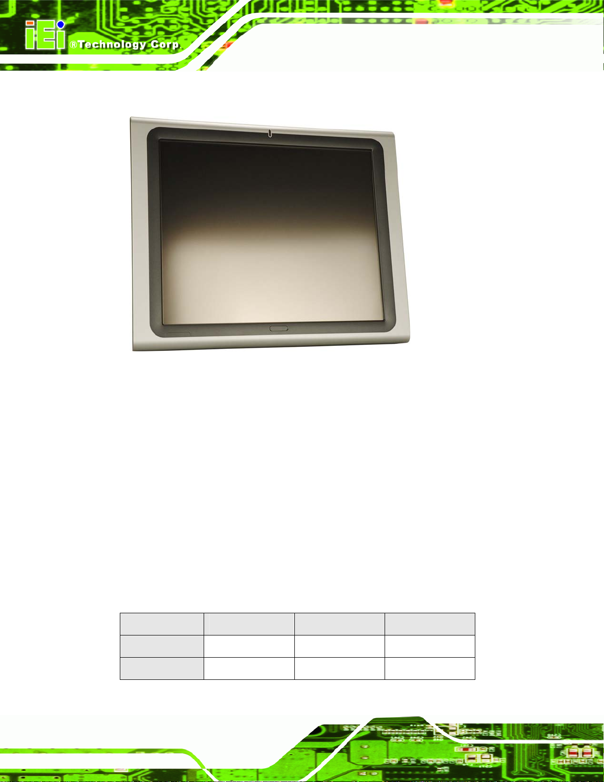
Figure 1-1: AFL-AM2
The AFL-AM2 flat panel PC is a flexible, multi-functional and powerful flat panel PC that
can be applied in diverse operational environments and implemented in multi-faceted
applications. The AFL-AM2 comes fully kitted with a high-performance motherboard and a
host of other peripheral interface connectors. The integrated wireless LAN module
provides a wireless connection to a network and the Bluetooth module ensures an
uninterrupted wireless connection to connected Bluetooth devices. The flexible AT/ATX
power mode selection allows the AFOLUX series to meet multiple application
requirements. The AFL-AM2 is designed for ease of use and easy installation.
1.1.1 Model Variations
The models of the AFL-AM2 series are listed in Table 1-1.
AFL-15B-AM2 AFL-17B-AM2 AFL-19B-AM2
Page 2
Brightness
LCD
350 cd/m2 300 cd/m2 300 cd/m2
15” 17” 19”
Page 19

AFL-AM2 Panel PC
Memory
Wireless
Bluetooth
Touchscreen
HSDPA
Table 1-1: Model Variations
AFL-15B-AM2 AFL-17B-AM2 AFL-19B-AM2
1.0 GB DDR2
Yes
Yes
Yes
Optional
1.1.2 Applications
The AFL-AM2 all-in-one panel PC is designed for multiple applications. Its durability and
strength makes it an ideal choice for public access computers. Some possible applications
include:
Vehicle Interior device
o Truck PC
o Logistic car PC
General computing
o PC based testing center
o Distance learning
Industrial applications
o Plant environment monitoring system
o Factory automation platform
o Manufacturing shop flow
o Equipment and device control
Home and building automation
o Digital surveillance system
o E-home platform
o Home IA control terminal
Self-Service Kiosk
o Receptionist kiosk in hotel and business premises
o Self registration terminal in hospital and airport
o Ticket vending machine for transportation use
Page 3
Page 20

1.1.3 Standard Features
Some of the standard features of the AFL-AM2 flat panel PC include:
Rugged mechanism design with ABS/PC case
IP 64 dustproof and waterproof front panel
1.0 GB DDR2 memory
Bluetooth connectivity
Wireless LAN
eSATA port
Dual 10/100/1000 Mb/s Ethernet support
Simplified installation process
RoHS compliance
1.2 External Overview
AFL-AM2 Panel PC
The AFL-AM2 is a flat panel PC. The monitor and all internal components are enclosed in
an aluminum chassis. An ABS/PC plastic cover surrounds the aluminum chassis. VESA
compliant screw holes in the rear panel allow the AFL-AM2 to be attached to any VESA
compliant mounting. The access panel at the bottom of the AFL-AM2 gives access to a
VGA port, four USB ports, an eSATA port, two Ethernet ports, an RS-232/422/485 port, an
RS-232 port, an audio jack, power input and power switch.
Page 4
Page 21

AFL-AM2 Panel PC
1.2.1 Front Panel
The front side of the AFL-AM2 is a flat panel TFT LCD screen surrounded by an ABS/PC
plastic frame.
Figure 1-2: Front View
Page 5
Page 22

1.2.2 Rear Panel
The rear panel provides access to retention screw holes that support the wall mounting.
AFL-AM2 Panel PC
Refer to
Figure 1-3: Rear View
Figure 1-3.
1.2.3 Bottom Panel
The bottom panel of the AFL-AM2 has the following I/O interfaces (Figure 1-4):
1 x External SATA port
1 x RS-232 serial port connector
1 x RS-232/422/485 serial port connector
1 x AC power adapter connector
2 x RJ-45 10/100/1000 Mb/s Ethernet connectors
4 x USB 2.0 connectors
1 x Power switch
1 x Reset switch
1 x VGA port
Page 6
Page 23

AFL-AM2 Panel PC
Figure 1-4: External Peripheral Connectors
1.3 Internal Overview
The AFL-AM2 includes the following parts inside the aluminum internal cover.
AMD Athlon™ 64 X2 dual-core processor
1.0 GB DDR2 SO-DIMM
Antennas
Backlight inverter
Bluetooth module
CompactFlash® disk (optional)
HSDPA module (optional)
Hard drive (optional)
Two speakers
Wireless LAN card
Page 7
Page 24

AFL-AM2 Panel PC
Figure 1-5: Internal Overview
Page 8
Page 25

AFL-AM2 Panel PC
Chapter
2
2 Specifications
Page 9
Page 26

2.1 Introduction
The AFL-AM2 flat panel PC has the following preinstalled components:
1 x Motherboard
1 x TFT LCD screen
1 x Touch screen panel
1 x Inverter
1 x Wireless LAN module
1 x DDR2 memory module
1 x Bluetooth module
1 x AT/ATX switch
2 x Speakers
2 x System fans
AFL-AM2 Panel PC
The technical specifications for the system, and some of these components, are shown in
the sections below.
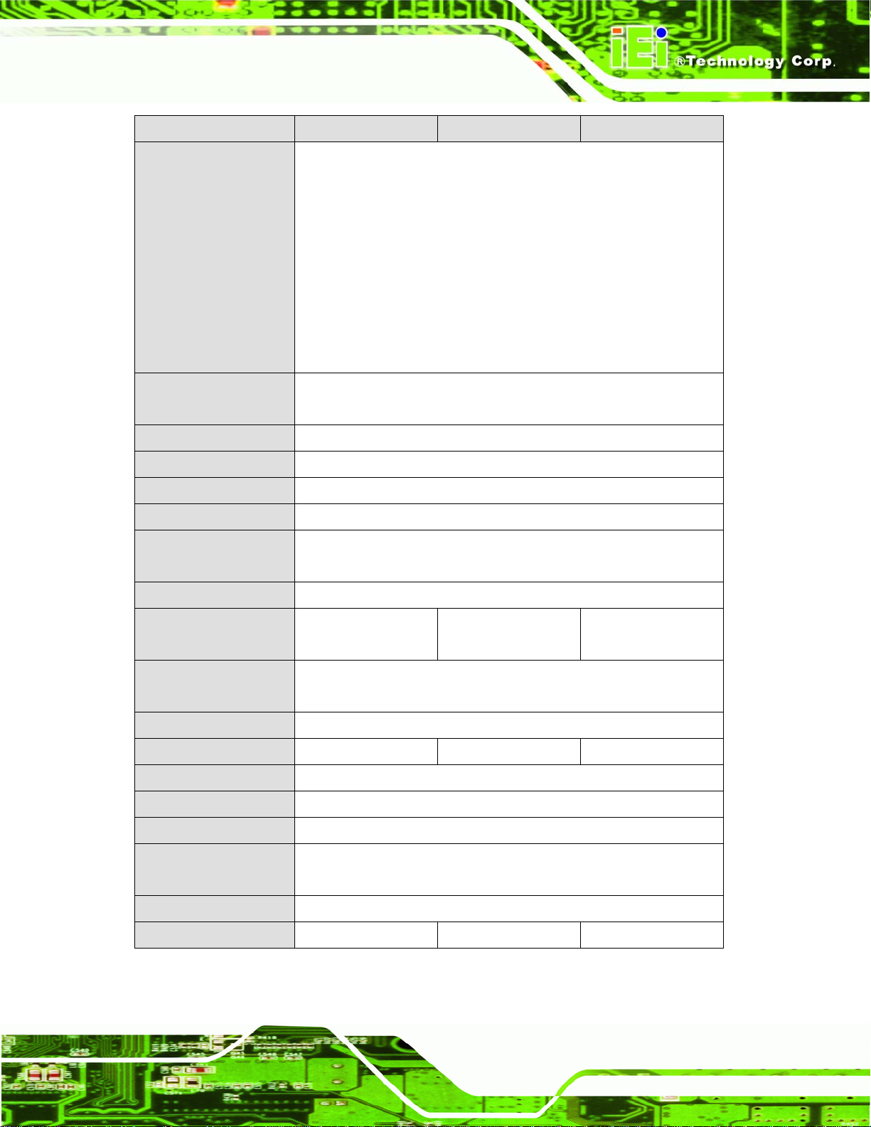
2.2 System Specifications
The technical specifications for the AFL-AM2 systems are listed in Table 2-1.
SPECIFICATION 15 inch 17 inch 19 inch
LCD Size 15” 17” 19”
Max Resolution 1024 x 768 1280 x 1024 1280 x 1024
Brightness (cd/m2) 350 300 300
Contrast Ratio 700:1 800:1 800:1
LCD Color 262K 16.7M 16.7M
Pixel Pitch (mm) 0.297 (H) x 0.297 (V) 0.264 (H) x 0.264 (V) 0.294 (H) x 0.294 (V)
Viewing Angle (H-V) 140 / 125 160 / 160 160 / 160
Backlight MTBF 50,000 hours
SBC Model AFLMB-690EAM2-R10
CPU AMD Athlon™ 64 X2 (up to 5200+)
Northbridge ATi M690T
Southbridge ATi SB600
Memory One 200-pin 1.0 GB dual-channel DDR2 SO-DIMM
Page 10
Page 27
AFL-AM2 Panel PC
SPECIFICATION 15 inch 17 inch 19 inch
I/O Ports 1 x Audio port
1 x eSATA port
1 x RS-232
1 x RS-232/422/485
2 x RJ-45
4 x USB 2.0
1 x Power switch
1 x Reset button
1 x VGA port
Storage 1 x 2.5” SATA
1 x CompactFlash® Type I/II
Speakers 2 x 3 W
Expansion 1 x PCIe Mini Wireless LAN Module
Construction Material ABS + PC Plastic front frame
LED Functions 1 x Power on/off LED
Mounting VESA MIS-D mount for panel, wall, rack (not for 19 inch model), stand
and arm mounting
Front Panel Color Silver
Dimensions
(W x H x D) (mm)
Operating
Temperature
Storage Temperature -20°C ~ 60°C
Net Weight 7.95 kg 10.0 kg 11.2 kg
IP Level IP 64
EMC CE, FCC, CCC, CB
Safety UL, CCC
Touch Screen Resistive Type 5 Wire
393.06 x 308.06 x
74.6
0°C ~ 40°C
(touch controller IC is on board and connected to COM4)
428 x 350 x 76 469.94 x 382.46 x
78.35
Power Input 12 V
Power Consumption 118 W 132 W 145 W
Table 2-1: AFL-AM2 System Specifications
Page 11
Page 28
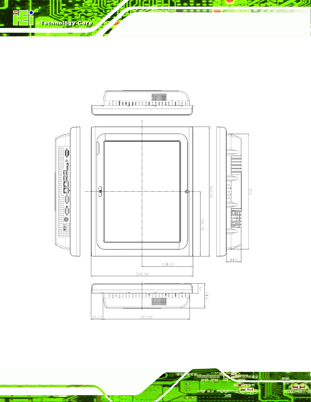
2.3 Dimensions
2.3.1 AFL-15B-AM2 Dimensions
The dimensions of the AFL-15B-AM2 flat panel PC are shown in Figure 2-1 below.
AFL-AM2 Panel PC
Page 12
Figure 2-1: AFL-15B-AM2 Front Dimensions (units in mm)
Page 29

AFL-AM2 Panel PC
Figure 2-2: AFL-15B-AM2 Rear Dimensions (units in mm)
Page 13
Page 30

2.3.2 AFL-17B-AM2 Dimensions
The dimensions of the AFL-17B-AM2 flat panel PC are shown in Figure 2-3 below.
AFL-AM2 Panel PC
Page 14
Figure 2-3: AFL-17B-AM2 Front Dimensions (units in mm)
Page 31

AFL-AM2 Panel PC
Figure 2-4: AFL-17B-AM2 Rear Dimensions (units in mm)
Page 15
Page 32

2.3.3 AFL-19B-AM2 Dimensions
The dimensions of the AFL-19B-AM2 flat panel PC are shown in Figure 2-3 below.
AFL-AM2 Panel PC
Page 16
Figure 2-5: AFL-19B-AM2 Front Dimensions (units in mm)
Page 33

AFL-AM2 Panel PC
Figure 2-6: AFL-19B-AM2 Rear Dimensions (units in mm)
2.4 CPU Support
The AFLMB-690EAM2-R10 motherboard comes with a socket AM2 CPU socket and
supports AMD Athlon™ 64 X2 Dual-Core processors up to 5200+.
Some of the specifications of these processors are listed below:
Two processing cores
True multitasking, allowing quick switching of programs
Cool’n’Quiet™ technology
Low power technologies
The AFL-AM2 supports the following AMD Socket AM2 processors
AMD Sempron™ processor
Page 17
Page 34

AMD Athlon™ 64 processor
AMD Athlon™ 64 X2 processor
2.5 System Chipsets
The AFLMB-690EAM2-R10 motherboard is comprised of an ATi M690T Northbridge
chipset and an ATi SB600 Southbridge chipset.
2.5.1 ATi M690T Overview
The M690T features an Integrated Graphics Processor (IGP) incorporated into the
Northbridge. The IGP supports a dedicated display cache (side-port) of up to 128 MB and
dynamic memory allocation scheme improves performance and reduces power. The
M690T uses shared system memory.
The AMD M690T has the following 2D acceleration features:
AFL-AM2 Panel PC
Optimized 128-bit engine, capable of processing four pixels per clock
Supports a maximum resolution of 2048 x 1536 @ 32bpp
Game acceleration including support for Microsoft's DirectDraw
The AMD M690T also has the following 3D acceleration features:
Full DirectX® 9.0 support
3D Texture support, including projective 3D textures
Anti-aliasing using multi-sampling algorithm with support for 2,4, and 6
samples
New generation rendering engine provides top 3D performance
Support for OpenGL format for Indirect Vertices in Vertex Walker
Motion video acceleration features on the AMD M690T include:
Enhanced MPEG-2 hardware decode acceleration
MPEG-4 decode support
Hardware acceleration for WMV9 playback
Page 18
Supports top quality DVD and time-shifted SDTV/HDTV television playback
with low CPU usage
Page 35

AFL-AM2 Panel PC
2.5.2 ATi SB600 Overview
The ATi SB600 Southbridge is connected to the Northbridge through the 1/2/4-lane A-Link
Xpress II interface which features high data transfer bandwidth. Some of the main features
of the SB600 are listed below:
Supports PCI rev 2.3 specifications
5 OHCI and 1 EHCI host controllers to support 10 USB ports (4 implemented)
SATA II AHCI controller with RAID 0, 1 and 10 support for 3.0 Gb/s SATA
drives
Single PATA channel with DMA support up to DMA-133
Audio link compliant with AC’97 rev 2.3
Two cascaded 8237 DMA controllers
2.6 Graphics Support
The ATi M690T Northbridge chipset has an integrated graphics engine that supports the
following display devices:
Analog CRT
Digital LVDS
2.6.1 Analog CRT Support
The VGA port is for connects a peripheral monitor to the AFL-AM2 system. A DB-15 VGA
connector on the external peripheral interface connector panel is interfaced to the ATi
M690T Northbridge. The ATi M690T supports analog CRT monitors with the following
features:
Supports max DAC frequency up to 400 MHz
24-bit RAMDAC support
DDC2B compliant
Up to 2048 x 1536 mode support
Page 19
Page 36

2.6.2 LVDS Support
The LVDS connector drives the built-in LCD panel. The 30-pin LVDS crimp connector is
connected to the Chrontel CH7308A chipset, which is connected to the M690T through
the SDVO interface.
18/24-bit outputs
Up to 140 megapixels per second
2.7 Memory
All processors supported by the AFL-AM2 have their own internal DDR2 memory
controller. The DDR2 controller has the following features:
Low-latency, high-bandwidth
800 MHz 128-bit DDR2 SDRAM controller
AFL-AM2 Panel PC
The DDR2 controller on the processor is interfaced to one SO-DIMM socket on the
AFL-AM2.
Figure 2-7: SO-DIMM Socket
2.8 Storage
There following storage options are available:
Supports one un-buffered DDR2 SO-DIMM
Each SO-DIMM has a maximum capacity of 1.0 GB
CompactFlash®
Page 20
SATA hard drive
Page 37

AFL-AM2 Panel PC
2.8.1 CompactFlash®
The CompactFlash® socket supports standard CompactFlash® Type I and
CompactFlash® Type II cards. The chipset flash interface is multiplexed with an IDE
interface and can be connected to an array of industry standard NAND Flash or NOR
Flash devices. The CompactFlash® slot location is shown below.
Figure 2-8: CompactFlash® Slot
2.8.2 SATA Hard Drive
The integrated SATA controller supports two SATA drives with independent DMA
operations. One SATA port is implemented internally for the internal 2.5” SATA hard drive.
The second SATA port is implemented on the external connector panel through an eSATA
connector. SATA controller specifications are listed below.
Supports two SATA drives
Supports 3.0 Gb/s data transfer speeds
Supports Serial ATA Specification, Revision 1.0a
Page 21
Page 38

Figure 2-9: SATA Hard Drive Slot
2.9 Bluetooth Module
The AFL-AM2 are all integrated with a Bluetooth module. The Bluetooth module enables
AFL-AM2 Panel PC
the transmission between various peripheral devices through a Bluetooth network.
Figure 2-10: Bluetooth Module
Bluetooth enabled peripheral devices include:
Headsets
Barcode readers
PDAs
Printers
Cell phones
Page 22
Keyboards and mice
Some of the major features of the Bluetooth module are listed below:
Bluetooth v2.0 compliant
Page 39

AFL-AM2 Panel PC
Uses 2.402 GHz – 2.480 GHz unlicensed ISM band
Class 2 output power (under 4 dBm)
USB 2.0 interface
2.10 HSDPA Module (Optional)
The HSDPA module is one of the OEM options for the AFL-AM2.
Figure 2-11: HSDPA Module
The HSDPA module connects to 3G and 3.5G cellular networks. The connectivity
provided by the HSDPA module allows the AFL-AM2 to connect through the Internet to
remote networks, allowing the AFL-AM2 to send and receive from wherever there is
cellular coverage.
Page 23
Page 40

2.11 Wireless LAN
The IEEE 802.11a/b/g compliant wireless module is pre-installed in the system and
provides wireless connectivity at up to 54 Mb/s. The wireless module is interfaced to the
system chipset through the USB interface in the PCIe Mini slot.
Figure 2-12: Wireless LAN Module
AFL-AM2 Panel PC
Some of the features of the wireless module are listed below.
Compliant with IEEE 802.11a, 802.11b and 802.11g standards
USB 2.0 interface (via the PCIe Mini slot)
VIA® Solomon VT6656 wireless LAN controller
2.12 Gigabit Ethernet
The Broadcom BCM5787M PCI Express (PCIe) GbE controller is a 10/100/1000BASE-T
Ethernet LAN controller. The BCM5787M combines a triple-speed IEEE 802.3 compliant
Media Access Controller (MAC) with a triple-speed Ethernet transceiver, a PCIe bus
interface, and an on-chip buffer memory.
Page 24
Figure 2-13: Ethernet
Some of the BCM5787 controller features are listed below:
Page 41

AFL-AM2 Panel PC
Integrated 10/100/1000BASE-T transceiver
Automatic MDI crossover function
PCIe v1.0a
10/100/1000BASE-T full/half-duplex MAC
Wake on LAN support meeting the ACPI requirements
Statistics for SNMP MIB II, Ethernet-like MIB, and Ethernet MIB (802.3z,
clause 30)
Serial EEPROM or serial flash support
JTAG support
2.13 Front Panel
The front panel of the AFL-AM2 consists of an LCD monitor and a touch screen panel.
2.13.1 Flat Screen
The AFL-AM2 comes with a TFT LCD monitor. The tough construction of the TFT monitor
allows the AFL-AM2 to withstand the conditions it is likely to be exposed to during regular
use. Some of the specifications of the TFT monitors are shown below:
Pixel pitch of 0.297 mm or less
700:1 contrast ratio or better
300 cd/m
8 msec optical response time or less
o
0
C to 50oC operating temperature
2
or greater
2.13.2 Touch Screen
The touch screen panel on the AFL-AM2 allows complete user interaction without the
need for a keyboard or mouse. Some of the features of the touch panel are listed below.
5-wire analog resistive type
78% transmission
Control chipset built onto the motherboard
-10
o
C to 50oC operating temperature
7 V maximum voltage
Page 25
Page 42

2.14 OEM Options
Some of the peripheral device connectors are not connected to any devices. These
connectors are reserved for OEM customizations. For a customized option, please contact
the vendor, reseller, or IEI sales representative.
AFL-AM2 Panel PC
Page 26
Page 43
AFL-AM2 Panel PC
Chapter
3
3 Installation
Page 27
Page 44

3.1 Installation Precautions
When installing the flat panel PC, please follow the precautions listed below:
Power turned off: When installing the flat panel PC, make sure the power is
off. Failing to turn off the power may cause severe injury to the body and/or
damage to the system.
Certified Engineers: Only certified engineers should install and modify
onboard functionalities.
Mounting: The flat panel PC is a heavy device. When mounting the system
onto a rack, panel, wall or arm please make sure that at least two people are
assisting with the procedure.
Anti-static Discharge: If a user open the rear panel of the flat panel PC, to
configure the jumpers or plug in added peripheral devices, ground themselves
first and wear an anti-static wristband.
AFL-AM2 Panel PC
3.2 Preinstalled Components
The following components are all preinstalled.
Motherboard
Backlight inverter
TFT LCD screen
1.0 GB DDR2 memory module
Resistive type touch screen panel
Wireless LAN module
Bluetooth module
AT/ATX power switch
Preinstalled OEM customizations may include the following.
CompactFlash® card with Windows XPE or Windows Embedded 5.0
Different DDR2 memory module
2.5” SATA hard disk drive
Page 28
HSDPA module
Installation of some of the components is described in the following sections.
Page 45

AFL-AM2 Panel PC
3.3 Installation and Configuration Steps
The following installation steps must be followed.
Step 1: Unpack the flat panel PC
Step 2: Install the CompactFlash® card (optional)
Step 3: Install the HSDPA module (optional)
Step 4: Install the hard drive (optional)
Step 5: Mount the flat panel PC
Step 6: Connect peripheral devices
Step 7: Configure the systemStep 0:
3.4 Unpacking
To unpack the flat panel PC, follow the steps below:
WARNING!
The front side LCD screen has a protective plastic cover stuck to the
screen. Only remove the plastic cover after the flat panel PC has been
properly installed. This ensures the screen is protected during the
installation process.
Step 1: Use box cutters, a knife or a sharp pair of scissors to cut the tape that seals the
top side of the external (second) box.
Step 2: Open the external (second) box.
Step 3: Use box cutters, a knife or a sharp pair of scissors to cut the tape that seals the
top side of the internal (first) box.
Step 4: Lift the monitor out of the boxes.
Page 29
Page 46

Step 5: Remove both polystyrene ends, one from each side.
Step 6: Pull the plastic cover off the flat panel PC.
Step 7: Make sure all the components listed in the packing list are present.
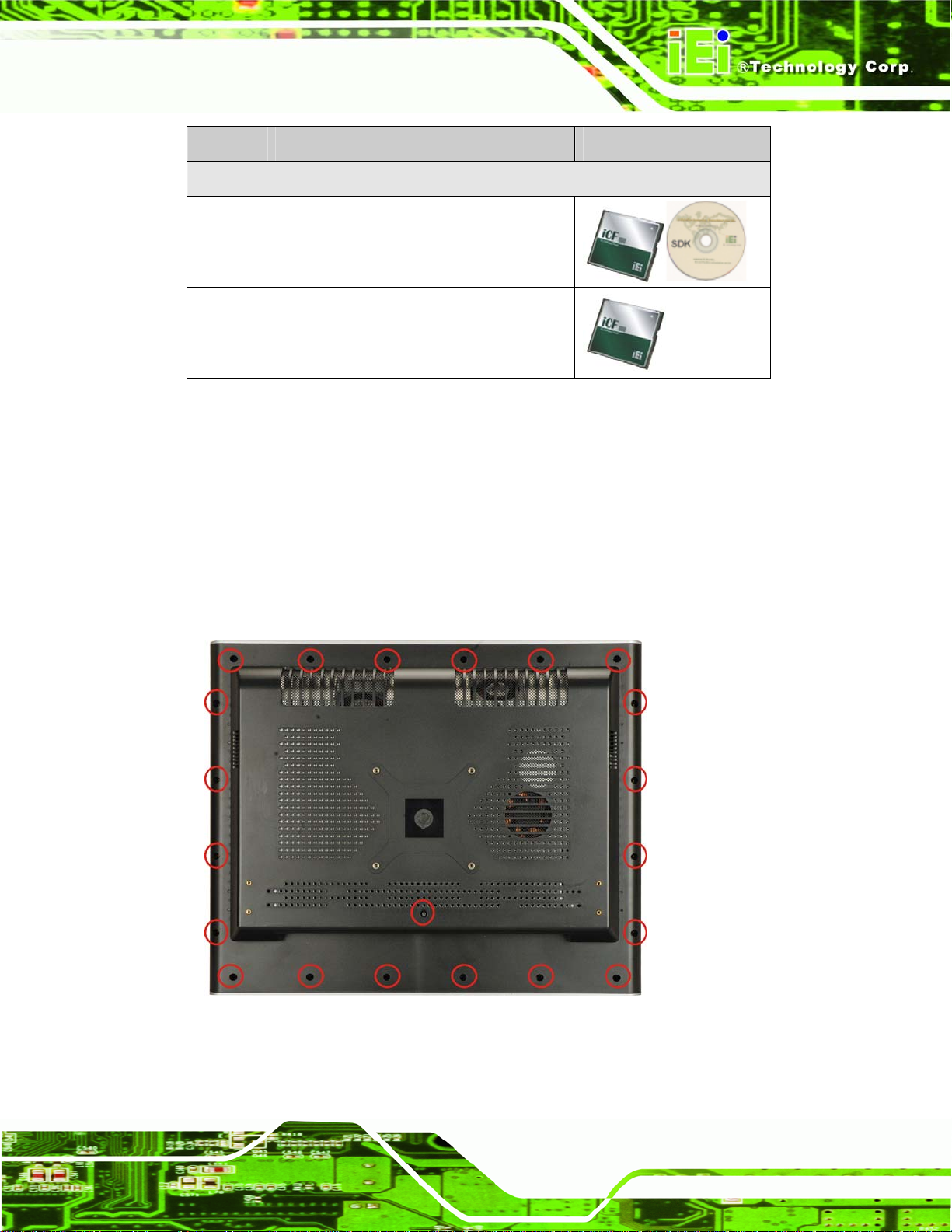
3.4.1 Packing List
The AFL-AM2 flat panel PC is shipped with the following components:
Quantity Item Image
Standard
1 AFL-AM2 panel PC
AFL-AM2 Panel PC
1 Power adapter
1 Power cord
1 User manual and driver CD
1 Touch pen
1 SATA cable
1 Screw kit
Page 30
Page 47
AFL-AM2 Panel PC
Quantity Item Image
Optional
1 128MB CompactFlash® card with
Windows CE 5.0 pre-installed and SDK
1 1GB CompactFlash® card with Windows
XPE pre-installed
If any of these items are missing or damaged, contact the distributor or sales
representative immediately.
3.5 CompactFlash® Card Installation
The AFL-AM2 has one CompactFlash® Type I/II slot inside the rear panel. To install the
CF card, follow the instructions below.
Step 1: Remove the retention screws (
Figure 3-1) and lift the cover off the flat panel PC.
Figure 3-1: Back Cover Retention Screws
Page 31
Page 48
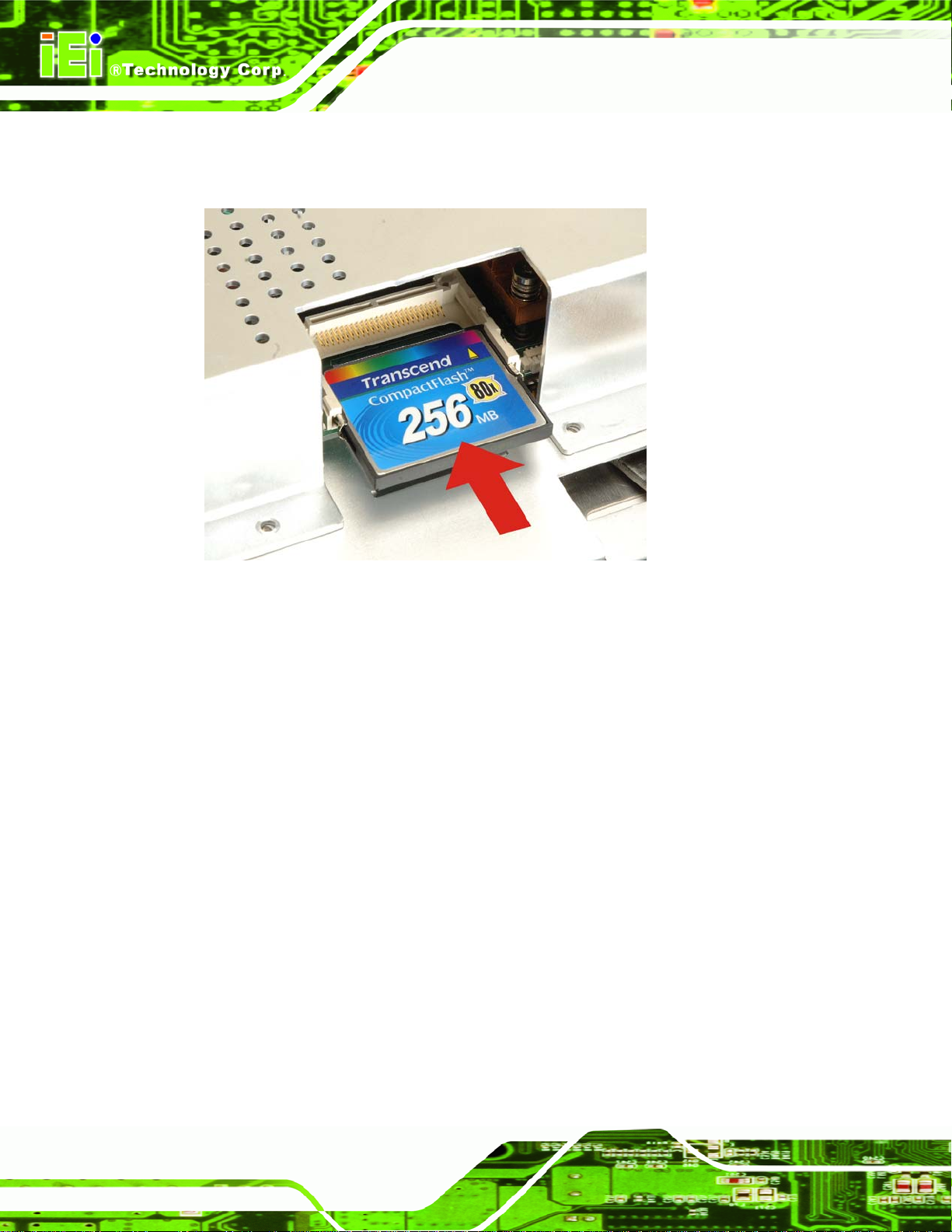
Step 2: Locate the CF slot. Align the CF card with the guides on the slot. Insert a CF
AFL-AM2 Panel PC
card into the slot (
Figure 3-2: CF Card Location
Figure 3-2).
Step 3: Replace the plastic back cover and fasten the retention screws. Step 0:
3.6 HSDPA Module Installation
The HSDPA module attaches to a USB type A receptacle located under the back cover of
the AFL-AM2. To install the HSDPA module, follow the instructions below.
Step 1: Remove the plastic back cover.
Step 2: Remove the aluminum cover.
Step 3: Locate the HSDPA USB socket.
Step 4: Line up the HSDPA module with the USB slot and insert.
Page 32
Page 49

AFL-AM2 Panel PC
Figure 3-3: Insert HSDPA module
Step 5: Open the antenna on the HSDPA module.
Figure 3-4: HSDPA Antenna
Step 6: Replace the plastic black cover.Step 0:
Software drivers for the HSDPA module are included with the HSDPA module.
3.7 HDD Installation
To install the hard drive, please follow the steps below:
Step 1: Disconnect the system power cable.
Step 2: Remove the plastic back cover. See Section
Step 3: Remove the eight round head retention screws and three flat head retention
screws securing the internal aluminum cover (
3.5 above.
Figure 3-5).
Page 33
Page 50

Figure 3-5: Aluminum Back Cover Retention Screws
AFL-AM2 Panel PC
Step 4: Lift the aluminum cover to remove.
Step 5: Remove the four HDD bracket retention screws (
bracket off the panel PC.
Figure 3-6: AFL-AM2 Hard Drive Bracket Retention Screws
Figure 3-6) and lift the HDD
Page 34
Step 6: Attach the hard drive to the hard drive bracket. To do this, align the four retention
screw holes on the hard drive with the screw holes on the hard drive bracket.
Page 51

AFL-AM2 Panel PC
Fasten four flat head retention screws to secure the hard drive to the bracket
Figure 3-7).
(
Figure 3-7: Hard Drive Retention Screws
Step 7: Reinstall the hard drive bracket. Slide the hard drive bracket into its original
position, making sure the SATA connectors on the hard drive connect with the
SATA connectors on the motherboard.
Figure 3-8: Hard Drive Retention Screws
Step 8: Fasten the hard drive bracket screws.
Page 35
Page 52

Step 9: Replace the aluminum back cover to the chassis.
Step 10: Replace the plastic back cover.Step 0:
3.8 AT/ATX Mode Selection
AT and ATX power modes can both be used on the AFL-AM2. The selection is made
through an AT/ATX switch on the aluminum chassis inside the plastic back cover
(
Figure 3-9). To select AT mode or ATX mode, follow the steps below.
AFL-AM2 Panel PC
Step 1: Remove the plastic back cover. See Section
Step 2: Locate the AT/ATX switch at the bottom right on the aluminum chassis
Figure 3-9).
(
Figure 3-9: AT/ATX Switch Location
Step 3: Adjust the AT/ATX switch.
3.5 above.
Step 4: Replace the plastic back cover.Step 0:
3.8.1 AT Power Mode
With the AT mode selected, the power is controlled by a central power unit rather than a
power switch. The AFL-AM2 panel PC turns on automatically when the power is
connected. The AT mode benefits a production line to control multiple panel PCs from a
central management center and other applications including:
ATM
Page 36
Page 53

AFL-AM2 Panel PC
Self-service kiosk
Plant environment monitoring system
Factory automation platform
Manufacturing shop flow
3.8.2 ATX Power Mode
With the ATX mode selected, the AFL-AM2 panel PC goes in a standby mode when it is
turned off. The panel PC can be easily turned on via network or a power switch in standby
mode. Remote power control is perfect for advertising applications since the broadcasting
time for each panel PC can be set individually and controlled remotely. Other possible
applications include:
Security surveillance
Point-of-Sale (POS)
Advertising terminal
3.9 Mounting the System
WARNING!
When mounting the flat panel PC onto an arm, onto the wall or onto a
panel, it is better to have more than one person to help with the
installation to make sure the panel PC does not fall down and get
damaged.
The four methods of mounting the AFL-AM2 are listed below.
Wall mounting
Panel mounting
Arm mounting
Rack mounting
The four mounting methods are described below.
Page 37
Page 54

3.9.1 Wall Mounting
To mount the flat panel PC onto the wall, please follow the steps below.
Step 1: Select the location on the wall for the wall-mounting bracket.
Step 2: Carefully mark the locations of the four brackets screw holes on the wall.
Step 3: Drill four pilot holes at the marked locations on the wall for the bracket retention
screws.
Step 4: Align the wall-mounting bracket screw holes with the pilot holes.
Step 5: Secure the mounting-bracket to the wall by inserting the retention screws into
AFL-AM2 Panel PC
the four pilot holes and tightening them (
Figure 3-10: Wall-mounting Bracket
Step 6: Insert the four monitor mounting screws provided in the wall mounting kit into the
Figure 3-10).
Page 38
four screw holes on the real panel of the flat panel PC and tighten until the screw
shank is secured against the rear panel (
Step 7: Align the mounting screws on the monitor rear panel with the mounting holes on
the bracket.
Figure 3-11).
Page 55

AFL-AM2 Panel PC
Step 8: Carefully insert the screws through the holes and gently pull the monitor
downwards until the monitor rests securely in the slotted holes (
Ensure that all four of the mounting screws fit snuggly into their respective
slotted holes.
Figure 3-11).
Figure 3-11: Chassis Support Screws
NOTE:
In the diagram below the bracket is already installed on the wall.
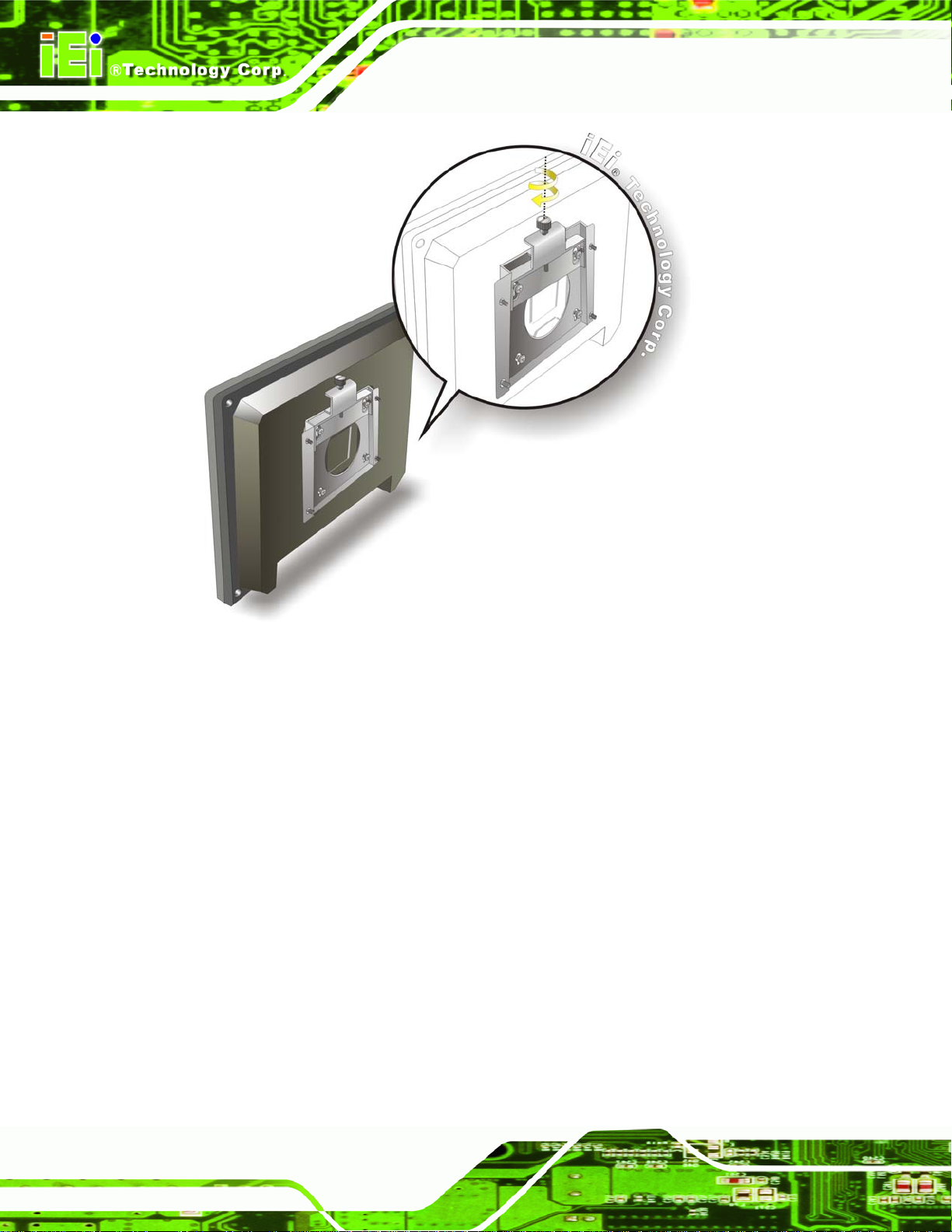
Step 9: Secure the panel PC by fastening the retention screw of the wall-mounting
bracket. (
Figure 3-12).Step 0:
Page 39
Page 56
AFL-AM2 Panel PC
Figure 3-12: Secure the Panel PC
3.9.2 Panel Mounting
To mount the AFL-AM2 flat panel PC into a panel, please follow the steps below.
Step 1: Select the position on the panel to mount the flat panel PC.
Step 2: Cut out a section from the panel that corresponds to the rear panel dimensions
of the flat panel PC. Take care that the panel section that is cut out is smaller
than the overall size of the metal frame that surrounds the flat panel PC but just
large enough for the rear panel of the flat panel PC to fit through (
Figure 3-14 and Figure 3-15).
Figure 3-13,
Page 40
Page 57

AFL-AM2 Panel PC
Figure 3-13: AFL-15B-AM2 Cutout Dimensions (units in mm)
Figure 3-14: AFL-17B-AM2 Cutout Dimensions (units in mm)
Page 41
Page 58

AFL-AM2 Panel PC
Figure 3-15: AFL-19B-AM2 Cutout Dimensions (units in mm)
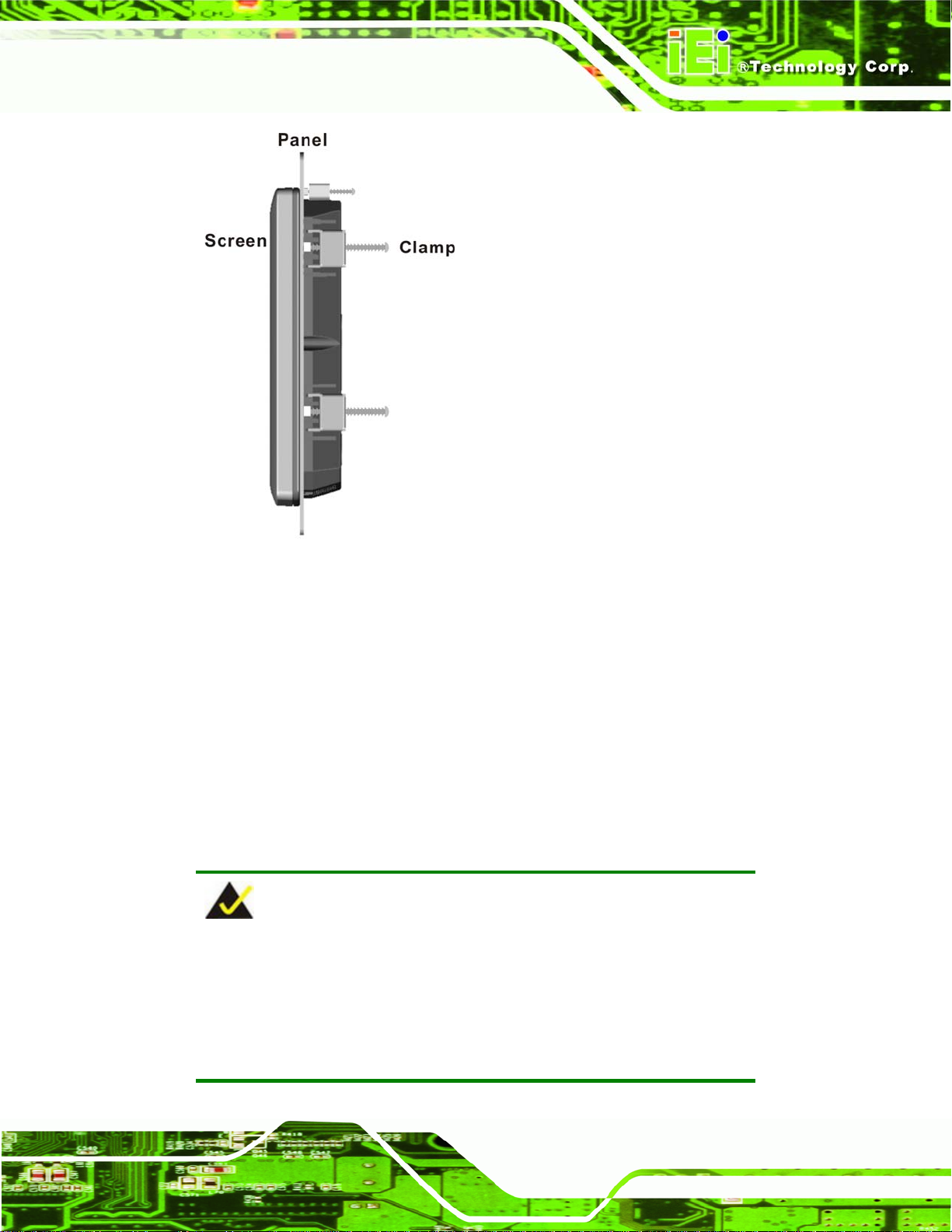
Step 3: Slide the flat panel PC through the hole until the aluminum frame is flush against
the panel.
Step 4: Insert the panel mounting clamps into the pre-formed holes along the edges of
the chassis, behind the aluminum frame.
Step 5: Tighten the screws that pass through the panel mounting clamps until the plastic
caps at the front of all the screws are firmly secured to the panel (
Figure 3-16).Step 0:
Page 42
Page 59
AFL-AM2 Panel PC
Figure 3-16: Tighten the Panel Mounting Clamp Screws
3.9.3 Arm Mounting
The AFL-AM2 is VESA (Video Electronics Standards Association) compliant and can be
mounted on an arm with a 100mm interface pad. To mount the AFL-AM2 on an arm,
please follow the steps below.
Step 1: The arm is a separately purchased item. Please correctly mount the arm onto
the surface it uses as a base. To do this, refer to the installation documentation
that came with the mounting arm.
NOTE:
When purchasing the arm please ensure that it is VESA compliant and
that the arm has a 100mm interface pad. If the mounting arm is not
VESA compliant it cannot be used to support the AFL-AM2 flat panel
PC.
Page 43
Page 60

Step 2: Once the mounting arm has been firmly attached to the surface, lift the flat panel
PC onto the interface pad of the mounting arm.
Step 3: Align the retention screw holes on the mounting arm interface with those in the
AFL-AM2 Panel PC
flat panel PC, as shown in
Figure 3-17: Arm Mounting Retention Screw Holes
Step 4: Secure the flat panel PC to the interface pad by inserting four retention screws
Figure 3-17.
through the bottom of the mounting arm interface pad and into the flat panel PC.
Step 0:
3.9.4 Cabinet and Rack Installation
The AFL-AM2 flat panel PC can be installed into a cabinet or rack. The installation
procedures are similar to the panel mounting installation. To do this, please follow the
steps below:
Page 44
Page 61

AFL-AM2 Panel PC
NOTE:
When purchasing the cabinet/rack installation bracket, make sure it is
compatible with both the AFL-AM2 flat panel PC and the rack/cabinet
into which the AFL-AM2 is installed.
Step 1: Slide the rear of the AFL-AM2 flat panel PC through the rack/cabinet bracket
until the aluminum frame is flush against the front of the bracket (
Figure 3-18: The Rack/Cabinet Bracket
Step 2: Insert the rack mounting clamps into the pre-formed holes along the edges of
the flat panel PC, behind the ABS/PC plastic frame.
Step 3: Tighten the screws that pass through the rack mounting clamps until the plastic
Figure 3-18).
caps at the front of all the screws are firmly secured to the bracket
Figure 3-19).
(
Page 45
Page 62

Figure 3-19: Secure the Rack/Cabinet Bracket
AFL-AM2 Panel PC
Step 4: Slide the flat panel PC with the attached rack/cabinet bracket into a rack or
cabinet (
Figure 3-20: Install into a Rack/Cabinet
Figure 3-20).
Page 46
Page 63

AFL-AM2 Panel PC
Step 5: Once the flat panel PC with the attached rack/cabinet bracket has been properly
inserted into the rack or cabinet, secure the front of the rack/cabinet bracket to
the front of the rack or cabinet (
3.10 Bottom Panel Connectors
All the external peripheral interface connectors are located at the bottom of the rear panel
on the AFL-AM2 panel PC.
3.10.1 LAN Connection
There are two external RJ-45 LAN connectors. The RJ-45 connectors enable connection
to an external network. To connect a LAN cable with an RJ-45 connector, please follow
the instructions below.
Step 1: Locate the RJ-45 connectors on the bottom panel of the AFL-AM2.
Step 2: Align the connectors. Align the RJ-45 connector on the LAN cable with one of
the RJ-45 connectors on the bottom panel of the AFL-AM2. See
Figure 3-20).Step 0:
Figure 3-21.
Figure 3-21: LAN Connection
Page 47
Page 64

Step 3: Insert the LAN cable RJ-45 connector. Once aligned, gently insert the LAN
cable RJ-45 connector into the onboard RJ-45 connector. Step 0:
3.10.2 Serial Device Connection
The AFL-AM2 has two single female DB-9 connectors on the bottom panel for a serial
device. Follow the steps below to connect a serial device to the AFL-AM2 panel PC.
Step 1: Locate the DB-9 connector. The location of the DB-9 connector is shown in
Chapter 2.
Step 2: Insert the serial connector. Insert the DB-9 connector of a serial device into
AFL-AM2 Panel PC
the DB-9 connector on the bottom panel. See
Figure 3-22.
Page 48
Figure 3-22: Serial Device Connector
Step 3: Secure the connector. Secure the serial device connector to the external
interface by tightening the two retention screws on either side of the connector.Step 0:
Page 65

AFL-AM2 Panel PC
3.10.3 USB Device Connection
There are four external USB 2.0 connectors. All connectors are perpendicular to the
AFL-AM2. To connect a USB 2.0 or USB 1.1 device, please follow the instructions below.
Step 1: Locate the USB connectors. The locations of the USB connectors are shown
in Chapter 2.
Step 2: Align the connectors. Align the USB device connector with one of the
connectors on the bottom panel. See
Figure 3-23.
Figure 3-23: USB Device Connection
Step 3: Insert the device connector. Once aligned, gently insert the USB device
connector into the onboard connector. Step 0:
Page 49
Page 66

3.10.4 VGA Monitor Connection
The AFL-AM2 has a single female DB-15 connector on the external peripheral interface
panel. The DB-15 connector is connected to a CRT or VGA monitor. To connect a monitor
to the AFL-AM2, please follow the instructions below.
Step 1: Locate the female DB-15 connector. The location of the female DB-15
connector is shown in Chapter 3.
Step 2: Align the VGA connector. Align the male DB-15 connector on the VGA screen
cable with the female DB-15 connector on the external peripheral interface.
Step 3: Insert the VGA connector. Once the connectors are properly aligned with the
insert the male connector from the VGA screen into the female connector on the
AFL-AM2 Panel PC
AFL-AM2. See
Figure 3-24: VGA Connector
Step 4: Secure the connector. Secure the DB-15 VGA connector from the VGA
monitor to the external interface by tightening the two retention screws on either
Figure 3-24.
Page 50
side of the connector. Step 0:
Page 67

AFL-AM2 Panel PC
4 System Maintenance
Chapter
4
Page 51
Page 68
4.1 Introduction
If the components of the AFL-AM2 fail they must be replaced, such as the wireless LAN
module or the motherboard. Please contact the system reseller or vendor to purchase the
replacement parts. Back cover removal instructions and jumper settings for the AFL-AM2
are described below.
4.2 Motherboard Replacement
A user cannot replace a motherboard. If the motherboard fails it must be shipped back to
IEI to be replaced. If the system motherboard has failed, please contact the system
vendor, reseller or an IEI sales person directly.
4.3 Internal Aluminum Cover Removal
AFL-AM2 Panel PC
WARNING!
T urn th e po wer off before remov ing the back cov er. Failing to do so
may lead to severe damage of AFL-AM2 and injury to the body.
WARNING!
Take antistatic precautions when working with internal
components. The interior of the AFL-AM2 contains very sensitive
electronic components. These components are easily damaged by
electrostatic discharge (ESD). Before working with the internal
components make sure all the anti-static precautions described earlier
have been observed.
To replace any of the following components,
Page 52
DDR2 memory module
Wireless LAN module
Inverter
Page 69

AFL-AM2 Panel PC
The internal aluminum back cover of the AFL-AM2 must be removed. To remove the
aluminum back cover, remove the retention screws indicated in the sections below.
Remove the following screws:
5 x Flat head screws
11 x Round head screws
Screw positions are indicated below (
Figure 4-1: AFL-19B-AM2 Aluminum Back Cover Retention Screws
Figure 4-1).
4.4 CPU Replacement
The CPU is preinstalled. If the CPU needs to be replaced because it fails or needs to be
upgraded, follow the instructions below to remove the heatsink and replace the CPU.
4.4.1 Heatsink Removal
Step 1: Remove the system fan holding the heatsink in place. Remove the two
screws and unclip the power cable to remove the system fan.
Page 53
Page 70

Figure 4-2: System Fan Removal
AFL-AM2 Panel PC
Step 2: Unclip the CPU fan cable and unscrew the CPU heatsink screws. Locate the
CPU fan power cable and detach it from the fan power wafer on the
motherboard. Unscrew the four retaining screws holding the CPU heatsink in
place. The heatsink screws are the four larger screws, it is not necessary to
undo the four smaller screws that hold the CPU fan in place.
Page 54
Figure 4-3: Heatsink Screws
Page 71
AFL-AM2 Panel PC
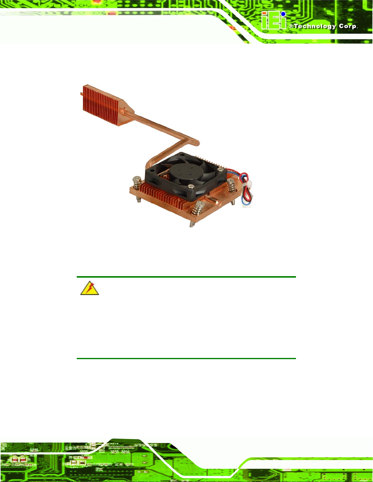
Step 3: Remove the heatsink from the motherboard. The figure below shows the
heatsink after removal. The CPU fan is still attached. Step 0:
Figure 4-4: CPU Heatsink
4.4.2 Socket AM2 CPU Installation
WARNING:
CPUs are expensive and sensitive components. When installing the
CPU please be careful not to damage it in anyway. Make sure the CPU
is installed properly and ensure the correct cooling kit is properly
installed.
To install a socket AM2 CPU onto the AFL-AM2, follow the steps below:
Page 55
Page 72

AFL-AM2 Panel PC
WARNING:
When handling the CPU, only hold it on the sides. DO NOT touch the
pins at the bottom of the CPU.
Step 1: Inspect the CPU socket. Make sure there are no bent pins and make sure the
socket contacts are free of foreign material. If any debris is found, remove it with
compressed air.
Step 2: Open the CPU socket lever. Disengage the load lever by moving the lever
slightly outward to clear the retention tab. Rotate the load lever to a fully open
position. See
Step 3: Orientate the CPU properly. Make sure the IHS (Integrated Heat Sink) side is
facing upward. See
Step 4: Correctly position the CPU. Match the Pin 1 mark with the cut edge on the
CPU socket. See
Figure 4-5.
Figure 4-5.
Figure 4-5.
Page 56
Figure 4-5: Install the CPU
Step 5: Insert the CPU. Gently insert the CPU into the socket. If the CPU pins are
properly aligned, the CPU should slide into the CPU socket smoothly
Page 73

AFL-AM2 Panel PC
Step 6: Close the CPU socket. Re-engage the load lever by pushing it back to its
original position. Secure the load lever under the retention tab on the side of
CPU socket. Step 0:
4.5 Memory Module Replacement
The flat panel PC is preinstalled with a 1.0 GB DDR2 memory module. If the memory
module fails, follow the instructions below to replace the memory module.
Step 1: Remove the back cover. See Section
Step 2: Remove the internal aluminum back cover. See Section
Step 3: Locate the DDR2 memory module on the motherboard of the flat panel PC
Figure 4-6).
(
Figure 4-6: SO-DIMM Socket Location
Step 4: Remove the DDR2 memory module by pulling both the spring retainer clips
outward from the socket.
Step 5: Grasp the DDR2 memory module by the edges and carefully pull it out of the
3.5 above.
4.3 above.
socket.
Step 6: Install the new DDR2 memory module by pushing it into the socket at an angle
Figure 4-7).
(
Step 7: Gently pull the spring retainer clips of the SO-DIMM socket out and push the
rear of the DDR2 memory module down (
Step 8: Release the spring retainer clips on the SO-DIMM socket. They clip into place
and secure the DDR2 memory module in the socket.Step 0:
Figure 4-7).
Page 57
Page 74

Figure 4-7: DDR2 SO-DIMM Module Installation
4.6 Serial Port Setup
CN Label: COM1 – RS-232
AFL-AM2 Panel PC
COM3 – RS-232/422/485
CN Type:
CN Pinouts:
DB9 connectors
Table 4-1 and Figure 4-8
See
COM1 supports RS-232. COM3 supports RS-232, RS-422 and RS-485. Pinouts for
RS-232, RS-422 and RS-485 are shown below (these apply to all serial ports).
PIN NO. RS-232 RS-422 RS-485
1 DCD TX- DATA2 RX TX+ DATA+
3 TX
4 DTR
5 GND
6 DSR TR-
7 RTS TR+
8 CTS
Page 58
9 RI
Table 4-1: Serial Port Pinouts
Page 75

AFL-AM2 Panel PC
Figure 4-8: Serial Port Pin Location
4.7 Jumper Settings
WARNING:
System damage can occur if the jumper settings are changed. The
jumpers should not be changed under normal conditions.
NOTE:
A jumper is a metal bridge that is
used to close an electrical circuit. It
consists of two metal pins and a small
metal clip (often protected by a plastic
cover) that slides over the pins to
connect them. To CLOSE/SHORT a
jumper means connecting the pins of
the jumper with the plastic clip and to
OPEN a jumper means removing the
plastic clip from a jumper.
The motherboard jumpers are listed below.
Jumper
4.7.1 AT/ATX Power Selection Jumper (J13)......................................... 60
4.7.2 Clear CMOS Jumper (J7) ............................................................. 60
4.7.3 CompactFlash
®
Master/Slave Setup (J6) .....................................60
Page 59
Page 76
4.7.4 COM1 and COM3 RI and Voltage Selection (J12) .......................61
4.7.5 COM2 RI and voltage selection (J3) ............................................. 61
4.7.6 COM3 RS-232/422/485 Selection (J8) .........................................61
4.7.7 COM3 RS-422/485 Selection (J5) ................................................62
4.7.8 COM3 Terminator Setting (J10, J14) ............................................62
4.7.9 COM3 Mode Selection Jumper (J11)............................................ 62
4.7.10 LCD Type Selection (PA_ID1)..................................................... 63
4.7.11 LCD Voltage Setup (J1)...............................................................63
4.7.12 Touch Panel Setup (J4)............................................................... 63
4.7.1 AT/ATX Pow er Selection Jumper (J13)
This jumper is connected to the AT/ATX selection switch on the rear of the AFL-AM2.
J13 Description
AFL-AM2 Panel PC
Closed ATX Power
Open AT Power
Table 4-2: AT/ATX Power Selection Jumper
4.7.2 Clear CMOS Jumper (J7)
The Clear CMOS jumper setting is used to reset the CMOS to default settings.
J7 Description
1-2 Normal Operation
2-3 Clear CMOS Setup
Table 4-3: Clear CMOS Jumper Settings
4.7.3 CompactFlash® Master/Slave Setup (J6)
This jumper setting should not be changed under normal conditions. The CompactFlash®
Master/Slave jumper selects the CompactFlash® slot as the IDE master or IDE slave.
Page 60
Page 77

AFL-AM2 Panel PC
J6 Description
Open Slave
Closed Master
Table 4-4: CompactFlash® Master/Slave Setup
4.7.4 COM1 and COM3 RI and Voltage Selection (J12)
The COM1 and COM2 pin-9 signal can be selected as 12V, 5V or Ring.
J12 Description
1-3 COM1 as 12 V
2-4 COM2 as 12 V
5-7 COM1 as 5 V
6-8 COM2 as 5 V
7-9 COM1 as RI
8-10 COM2 as RI
Table 4-5: COM1 and COM3 RI and Voltage Settings
4.7.5 COM2 RI and voltage selection (J3)
The COM2 pin-9 signal can be selected as 12V, 5V or Ring.
J3 Description
1-2 12 V
3-4 RI
5-6 5 V
Table 4-6: COM2 RI and Voltage Selection
4.7.6 COM3 RS-232/422/485 Selection (J8)
The COM3 RS-232/422/485 selection jumper sets serial port COM3 as RS-232, RS-422
or RS-485.
Page 61
Page 78

J8 Description
1-2 RS-232
3-4 RS-422
5-6 RS-485
Table 4-7: COM3 RS-232/422/485 Selection
4.7.7 COM3 RS-422/485 Selection (J5)
The COM3 RS-422/485 selection jumper sets serial port COM3 as RS-422 or RS-485.
J5 Description
1-3, 2-4 RS-422
3-5, 4-6 RS-485
Table 4-8: COM3 RS-422/485 Selection Jumper
AFL-AM2 Panel PC
4.7.8 COM3 Terminator Setting (J10, J14)
The COM3 terminator jumpers are for terminating an RS-422 or RS-485 setup. The
default setting is for both J10 and J14 to be open. To remedy transmission problems with
cables over 1.5 km in length, try settings J10 and J14 to closed.
J10 J14 Description
Open Open Normal operation
Closed Closed Use terminator
Table 4-9: COM3 Terminator Setting
4.7.9 COM3 Mode Selection Jumper (J11)
The COM3 pin header sets the COM3 serial port as RS-232 or RS-422/485.
J11 Description
1-2, 4-5, 7-8, 10-11 RS-232
Page 62
2-3, 5-6, 8-9, 11-12 RS-422/RS-485
Table 4-10: COM3 Mode Selection Jumper
Page 79

AFL-AM2 Panel PC
4.7.10 LCD Type Selection (PA_ID1)
This jumper should not be changed from factory settings. The LCD type jumper
selects what kind of LCD screen is being used in the system. This jumper is preset to
match the specifications of the built-in screen.
PA_ID1 Description
1-2, 9-10 1024 x 768 (18-bit)
3-4, 9-10 1024 x 768 (24-bit)
1-2, 3-4, 9-10 1280 x 1024 (36-bit)
5-6, 9-10 1280 x 1024 (48-bit)
1-2, 5-6, 9-10 1600 x 1200 (48-bit)
3-4, 5-6, 9-10 1600 x 1200 (36-bit)
1-2, 3-4, 5-6, 9-10 1366 x 768 (18-bit)
Table 4-11: LCD Type Selection
4.7.11 LCD Voltage Setup (J1)
This jumper should not be changed from factory settings. The LCD voltage jumper
selects the voltage for the LCD screen being used in the system.
J1 Description
1-2 3.3 V
3-4 5 V
5-6 12 V
Table 4-12: LCD Type Selection
4.7.12 Touch Panel Setup (J4)
This jumper should not be changed from factory settings. The touch panel setup
jumper is set for the included touch panel.
J4 Description
1-2 Default
Page 63
Page 80

J4 Description
3-4 SENSE
Table 4-13: LCD Type Selection
AFL-AM2 Panel PC
Page 64
Page 81

AFL-AM2 Panel PC
Chapter
5
5 BIOS Setup
Page 65
Page 82

5.1 Introduction
A licensed copy of AMI BIOS is preprogrammed into the ROM BIOS. The BIOS setup
program allows users to modify the basic system configuration. This chapter describes
how to access the BIOS setup program and the configuration options that may be
changed.
5.1.1 Starting Setup
The AMI BIOS is activated when the computer is turned on. The setup program can be
activated in one of two ways.
AFL-AM2 Panel PC
1. Press the D
2. Press the D
message appears on the screen. 0.
If the message disappears before the D
again.
ELETE key as soon as the system is turned on or
ELETE key when the “Press Del to enter SETUP”
ELETE key is pressed, restart the computer and try
5.1.2 Using Setup
Use the arrow keys to highlight items, press ENTER to select, use the PageUp and
PageDown keys to change entries, press F1 for help and press E
keys are shown in.
Key Function
Up arrow Move to previous item
Down arrow Move to next item
Left arrow Move to the item on the left hand side
SC to quit. Navigation
Page 66
Right arrow Move to the item on the right hand side
Esc key Main Menu – Quit and not save changes into CMOS
Status Page Setup Menu and Option Page Setup Menu --
Exit current page and return to Main Menu
Page Up key Increase the numeric value or make changes
Page Dn key Decrease the numeric value or make changes
Page 83

AFL-AM2 Panel PC
Key Function
F1 key General help, only for Status Page Setup Menu and Option
F2 /F3 key Change color from total 16 colors. F2 to select color
F10 key Save all the CMOS changes, only for Main Menu
Table 5-1: BIOS Navigation Keys
5.1.3 Getting Help
When F1 is pressed a small help window describing the appropriate keys to use and the
Page Setup Menu
forward.
possible selections for the highlighted item appears. To exit the Help Window press E
the F1 key again.
5.1.4 Unable to Reboot After Configuration Changes
If the computer cannot boot after changes to the system configuration is made, CMOS
defaults. Use the jumper described in Chapter 5.
5.1.5 BIOS Menu Bar
The menu bar on top of the BIOS screen has the following main items:
Main – Changes the basic system configuration
Advanced – Changes the advanced system settings
PCI/PnP – Changes the advanced PCI/PnP settings
Boot – Changes the system boot configuration
Security – Sets User and Supervisor passwords
Chipset – Changes the chipset settings
SC or
Power – Changes power management settings
Exit – Selects exit options and loads default settings
The following sections completely describe the configuration options found in the menu
items at the top of the BIOS screen and listed above.
Page 67
Page 84

5.2 Main
The Main BIOS menu (BIOS Menu 1) appears when the BIOS Setup program is entered.
The Main menu gives an overview of the basic system information.
AFL-AM2 Panel PC
BIOS Menu 1: Main
System Overview
The System Overvie w lists a brief summary of different system components. The fields in
System Overview cannot be changed. The items shown in the system overview include:
AMI BIOS: Displays auto-detected BIOS information
Processor: Displays auto-detected CPU specifications
Page 68
o Version: Current BIOS version
o Build Date: Date the current BIOS version was made
o ID: Installed BIOS ID
o Type: Names the currently installed processor
o Speed: Lists the processor speed
o Count: The number of CPUs on the motherboard
Page 85

AFL-AM2 Panel PC
System Memory: Displays the auto-detected system memory.
o Size: Lists memory size
The System Overview field also has two user configurable fields:
System Time [hh:mm:ss]
Use the System Time option to set the system time. Manually enter the hours, minutes
and seconds.
System Date [dd/mm/yyyy]
Use the System Date option to set the system date. Manually enter the day, month and
year.
5.3 Advanced
Use the Advanced menu to configure the CPU and peripheral devices through the
following sub-menus:
WARNING:
Setting the wrong values in the sections below may cause the system
to malfunction. Make sure that the settings made are compatible with
the hardware.
CPU Configuration .................................................................................71
IDE Configuration................................................................................... 72
Super IO Configuration ..........................................................................79
Hardware Health Configuration..............................................................81
ACPI Configuration ................................................................................ 85
Remote Access Configuration................................................................ 86
USB Configuration ................................................................................. 89
Page 69
Page 86
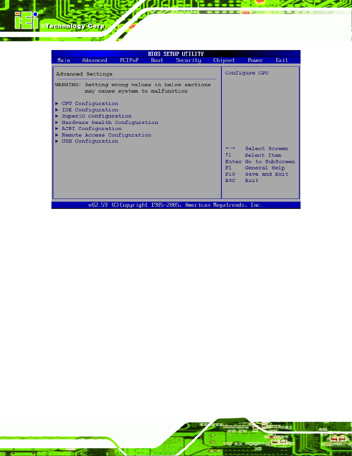
AFL-AM2 Panel PC
BIOS Menu 2: Advanced
Page 70
Page 87

AFL-AM2 Panel PC
5.3.1 CPU Configuration
Use the CPU Configuration menu (BIOS Menu 3) to view detailed CPU specifications and
configure the CPU.
BIOS Menu 3: CPU Configuration
The CPU Configuration menu (
Revision: Lists the CPU revision number
Cache L1: Lists the CPU L1 cache size
Cache L2: Lists the CPU L2 cache size
Speed: Lists the CPU processing speed
Current FSB Multiplier: Specifies how much the FSB is increased by
Maximum FSB Multiplier: Specifies the maximum the FSB can be increased
Able to Change Freq: Specifies the CPU frequency cannot be changed.
uCode Patch Level:
BIOS Menu 3) lists the following CPU details:
Page 71
Page 88

5.3.2 IDE Configuration
Use the IDE Configuration menu (BIOS Menu 4) to change and/or set the configuration
of the IDE devices installed in the system.
AFL-AM2 Panel PC
BIOS Menu 4: IDE Configuration
OnBoard PCI IDE Controller [Primary]
The OnBoard PCI IDE Controller BIOS option specifies the IDE channels used by the
onboard PCI IDE controller. The following configuration options are available.
Page 72
Disabled
Primary
Prevents the system from using the onboard IDE
Only allows the system to detect the Primary IDE
controller
channel, including both the Primary Master and Primary
Slave)
Page 89

AFL-AM2 Panel PC
IDE Master and IDE Slave
When entering setup, BIOS auto detects the presence of IDE devices. BIOS displays the
status of the auto detected IDE devices. The following IDE devices are detected and are
shown in the IDE Configuration menu:
Primary IDE Master
Primary IDE Slave
Secondary IDE Master
Secondary IDE Slave
Third IDE Master
Third IDE Slave
The IDE Configuration menu (
IDE devices installed in the system. If an IDE device is detected, and one of the above
listed four BIOS configuration options are selected, the IDE configuration options shown in
Section
5.3.2.1 appear.
BIOS Menu 4) allows changes to the configurations for the
Page 73
Page 90
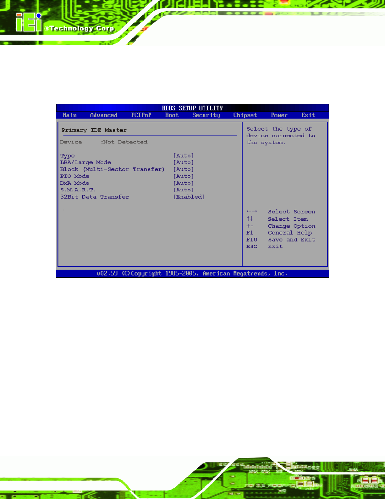
5.3.2.1 IDE Master, IDE Slave
Use the IDE Master and IDE Slave configuration menu to view both primary and
secondary IDE device details and configure the IDE devices connected to the system.
AFL-AM2 Panel PC
BIOS Menu 5: IDE Master and IDE Slave Configuration
Auto-Detected Drive Parameters
The “grayed-out” items in the left frame are IDE disk drive parameters automatically
detected from the firmware of the selected IDE disk drive. The drive parameters are listed
as follows:
Device: Lists the device type (e.g. hard disk, CD-ROM etc.)
Type: Indicates the type of devices a user can manually select
Vendor: Lists the device manufacturer
Size: List the storage capacity of the device.
LBA Mode: Indicates whether the LBA (Logical Block Addressing) is a
method of addressing data on a disk drive is supported or not.
Page 74
Page 91

AFL-AM2 Panel PC
Block Mode: Block mode boosts IDE drive performance by increasing the
amount of data transferred. Only 512 bytes of data can be transferred per
interrupt if block mode is not used. Block mode allows transfers of up to 64 KB
per interrupt.
PIO Mode: Indicates the PIO mode of the installed device.
Async DMA: Indicates the highest Asynchronous DMA Mode that is
supported.
Ultra DMA: Indicates the highest Synchronous DMA Mode that is supported.
S.M.A.R.T.: Indicates whether or not the Self-Monitoring Analysis and
Reporting Technology protocol is supported.
32Bit Data Transfer: Enables 32-bit data transfer.
Type [Auto]
Use the Type BIOS option select the type of device the AMIBIOS attempts to boot from
after the Power-On Self-Test (POST) is complete.
Not Installed
Auto DEFAULT
CD/DVD
ARMD
BIOS is prevented from searching for an IDE disk
drive on the specified channel.
The BIOS auto detects the IDE disk drive type
attached to the specified channel. This setting should
be used if an IDE hard disk drive is attached to the
specified channel.
The CD/DVD option specifies that an IDE CD-ROM
drive is attached to the specified IDE channel. The
BIOS does not attempt to search for other types of
IDE disk drives on the specified channel.
This option specifies an ATAPI Removable Media
Device. These include, but are not limited to:
ZIP
LS-120
Page 75
Page 92

LBA/Large Mode [Auto]
Use the LBA/Large Mode option to disable or enable BIOS to auto detects LBA (Logical
Block Addressing). LBA is a method of addressing data on a disk drive. In LBA mode, the
maximum drive capacity is 137 GB.
AFL-AM2 Panel PC
Disabled
Auto DEFAULT
Block (Multi Sector Transfer) [Auto]
Use the Block (Multi Sector Transfer) to disable or enable BIOS to auto detect if the
device supports multi-sector transfers.
Disabled
Auto DEFAULT
BIOS is prevented from using the LBA mode control on
the specified channel.
BIOS auto detects the LBA mode control on the specified
channel.
BIOS is prevented from using Multi-Sector Transfer on the
specified channel. The data to and from the device occurs
one sector at a time.
BIOS auto detects Multi-Sector Transfer support on the
drive on the specified channel. If supported the data
transfer to and from the device occurs multiple sectors at
a time.
PIO Mode [Auto]
Use the PIO Mode option to select the IDE PIO (Programmable I/O) mode program timing
cycles between the IDE drive and the programmable IDE controller. As the PIO mode
increases, the cycle time decreases.
Auto DEFAULT
0
1
2
Page 76
BIOS auto detects the PIO mode. Use this value if the IDE disk
drive support cannot be determined.
PIO mode 0 selected with a maximum transfer rate of 3.3 MB/s
PIO mode 1 selected with a maximum transfer rate of 5.2 MB/s
PIO mode 2 selected with a maximum transfer rate of 8.3 MB/s
Page 93

AFL-AM2 Panel PC
3
4
DMA Mode [Auto]
Use the DMA Mode BIOS selection to adjust the DMA mode options.
Auto DEFAULT
SWDMA0
SWDMA1
PIO mode 3 selected with a maximum transfer rate of 11.1 MB/s
PIO mode 4 selected with a maximum transfer rate of 16.6 MB/s
(This setting generally works with all hard disk drives
manufactured after 1999. For other disk drives, such as IDE
CD-ROM drives, check the specifications of the drive.)
BIOS auto detects the DMA mode. Use this value if the IDE
disk drive support cannot be determined.
Single Word DMA mode 0 selected with a maximum data
transfer rate of 2.1 MB/s
Single Word DMA mode 1 selected with a maximum data
transfer rate of 4.2 MB/s
SWDMA2
MWDMA0
MWDMA1
MWDMA2
UDMA1
UDMA1
UDMA2
Single Word DMA mode 2 selected with a maximum data
transfer rate of 8.3 MB/s
Multi Word DMA mode 0 selected with a maximum data
transfer rate of 4.2 MB/s
Multi Word DMA mode 1 selected with a maximum data
transfer rate of 13.3 MB/s
Multi Word DMA mode 2 selected with a maximum data
transfer rate of 16.6 MB/s
Ultra DMA mode 0 selected with a maximum data transfer
rate of 16.6MB/s
Ultra DMA mode 1 selected with a maximum data transfer
rate of 25 MB/s
Ultra DMA mode 2 selected with a maximum data transfer
rate of 33.3 MB/s
Page 77
Page 94

AFL-AM2 Panel PC
UDMA3
UDMA4
UDMA5
S.M.A.R.T [Auto]
Use the S.M.A.R.T option to auto-detect, disable or enable Self-Monitoring Analysis and
Reporting Technology (SMART) on the drive on the specified channel. S.M.A.R.T predicts
impending drive failures. The S.M.A.R.T BIOS option enables or disables this function.
Auto DEFAULT
Ultra DMA mode 3 selected with a maximum data transfer
rate of 44 MB/s (To use this mode, it is required that an
80-conductor ATA cable is used.)
Ultra DMA mode 4 selected with a maximum data transfer
rate of 66.6 MB/s (To use this mode, it is required that an
80-conductor ATA cable is used.)
Ultra DMA mode 5 selected with a maximum data transfer
rate of 100 MB/s (To use this mode, it is required that an
80-conductor ATA cable is used.)
BIOS auto detects HDD SMART support.
Disabled
Enabled
32Bit Data Transfer [Enabled]
Use the 32Bit Data Transfer BIOS option to enables or disable 32-bit data transfers.
Disabled
Enabled DEFAULT
Prevents BIOS from using the HDD SMART feature.
Allows BIOS to use the HDD SMART feature
Prevents the BIOS from using 32-bit data transfers.
Allows BIOS to use 32-bit data transfers on supported
hard disk drives.
Page 78
Page 95

AFL-AM2 Panel PC
5.3.3 Super IO Configuration
Use the Super IO Configuration menu (BIOS Menu 6) to set or change the
configurations for the FDD controllers, parallel ports and serial ports.
BIOS Menu 6: Super IO Configuration
Serial Port1 Address [3F8/IRQ4]
Use the Serial Port1 Address option to select the Serial Port 1 base address.
Disabled
3F8/IRQ4 DEFAULT
3E8/IRQ4
2E8/IRQ3
No base address is assigned to Serial Port 1
Serial Port 1 I/O port address is 3E8 and the interrupt
Serial Port 1 I/O port address is 2E8 and the interrupt
Serial Port 1 I/O port address is 3F8 and the interrupt
address is IRQ4
address is IRQ4
address is IRQ3
Page 79
Page 96

Serial Port2 Address [2F8/IRQ3]
Use the Serial Port2 Address option to select the Serial Port 2 base address.
AFL-AM2 Panel PC
Disabled
2F8/IRQ3 DEFAULT
3E8/IRQ4
2E8/IRQ3
Serial Port3 Address [3E8]
Use the Serial Port3 Address option to select the Serial Port 3 base address.
Disabled
3E8 DEFAULT
2E8
No base address is assigned to Serial Port 2
Serial Port 2 I/O port address is 3F8 and the interrupt
address is IRQ3
Serial Port 2 I/O port address is 3E8 and the interrupt
address is IRQ4
Serial Port 2 I/O port address is 2E8 and the interrupt
address is IRQ3
No base address is assigned to Serial Port 3
Serial Port 3 I/O port address is 3E8
Serial Port 3 I/O port address is 2E8
338
238
Select RS232 or RS422/485 [RS232]
Use the Select RS232 or RS422/485 option to select the communication protocol for
Serial Port 3.
RS232 DEFAULT
RS422/RS485
Serial Port4 Address [2E8]
Use the Serial Port4 Address option to select the Serial Port 4 base address.
Serial Port 3 I/O port address is 338
Serial Port 3 I/O port address is 238
RS-232 communication protocol is used on
Serial Port 3
RS-422 or RS-485 communication protocol is used on
Serial Port 3
Page 80
Page 97

AFL-AM2 Panel PC
Disabled
3E8
2E8 DEFAULT
338
238
No base address is assigned to Serial Port 4
Serial Port 4 I/O port address is 3E8
Serial Port 4 I/O port address is 2E8
Serial Port 4 I/O port address is 338
Serial Port 4 I/O port address is 238
5.3.4 Hardware Health Configuration
The Hardware Health Configuration menu (BIOS Menu 7) shows the operating
temperature, fan speeds and system voltages.
BIOS Menu 7: Hardware Health Configuration
The settings of the system fan and CPU fan can be adjusted. The two fan settings are:
FAN 1 Mode Setting
FAN 2 Mode Setting
Page 81
Page 98

FAN x Mode Setting [Automatic Mode]
Use the FAN x Mode Setting option to configure FAN x.
AFL-AM2 Panel PC
Full On Mode
Automatic mode D
PWM Manual mode
When the FAN x Mode Setting option is in the Automatic Mode, the following
parameters can be set.
Temperature x Limit of OFF
Temperature x Limit of Start
Fan x Start PWM
Slope PWM x
When the FAN x Mode Setting option is in the PWM Manual Mode, the following
parameters can be set.
Fan is on at full speed all the time
EFAULT
Pulse width modulation set manually
Fan is off when the temperature is low
enough. Parameters must be set by the
user.
Fan x PWM control
Temperature x Limit of OFF [000]
WARNING:
Setting this value too high may cause the fan to stop when the CPU is
at a high temperature and therefore cause the system to be damaged.
The Temperature x Limit of OFF option can only be set if the FAN x Mode Setting
option is set to Automatic Mode. Use the Temperature x Limit of OFF option to select
the CPU temperature at which the cooling fan should automatically turn off. To select a
value, select the Temperature x Limit of OFF option and enter a decimal number
between 000 and 127. The temperature range is specified below.
Page 82
Page 99

AFL-AM2 Panel PC
Minimum Value: 0°C
Maximum Value: 127°C
Temperature x Limit of St art [063]
WARNING:
Setting this value too high may cause the fan to start only when the
CPU is at a high temperature and therefore cause the system to be
damaged.
The Temperature x Limit of Start option can only be set if the Temperature x Mode
Setting option is set to Automatic Mode. Use the Temperature x Limit of Start option to
select the CPU temperature at which the cooling fan should automatically turn on. When
the fan starts, it rotates using the starting pulse width modulation (PWM) specified in the
Fan x Start PWM option below. To select a value, select the Temperature x Limit of
Start option and enter a decimal number between 000 and 127. The temperature range is
specified below.
Minimum Value: 0°C
Maximum Value: 127°C
Fan x Start PWM [002]
The Fan x Start PWM option can only be set if the FAN x Mode Setting option is set to
Automatic Mode. Use the Fan x Start PWM option to select the PWM mode the fan
starts to rotate with after the temperature specified in the Temperature x Limit of Start is
exceeded. The Super I/O chipset supports 128 PWM modes. To select a value, select the
Fan x Start PWM option and enter a decimal number between 000 and 127. The
temperature range is specified below.
PWM Minimum Mode: 0
PWM Maximum Mode: 127
Page 83
Page 100

Slope PWM x [1 PWM]
The Slope PWM x option can only be set if the FAN x Mode Setting option is set to
Automatic Mode. Use the Slope PWM x option to select the linear rate at which the PWM
mode increases with respect to an increase in temperature. A list of available options is
shown below:
0 PWM
1 PWM
2 PWM
4 PWM
8 PWM
16 PWM
32 PWM
64 PWM
AFL-AM2 Panel PC
The following system parameters and values are shown. The system parameters that are
monitored are:
System Temperatures: The following system temperatures are monitored
o CPU Temperature
o System Temperature 1
o System Temperature 2
Fan Speeds: The CPU cooling fan speed is monitored.
o CPU Fan Speed
o System Fan Speed
Voltages: The following system voltages are monitored
o CPU Core
o +1.20V
o +3.30V
o +5.0V
o +1.8V
o VBAT
Page 84
 Loading...