

Page 1
IEI Technology Corp.
User Manual
AFL-9652 series Flat Panel PC
MODEL:
AFL-9652 Series
All-in-one Flat Panel PC with Intel® Core2 Duo/Celeron® M,
Touch Screen, 802.11 a/b/g/n Wi-Fi, Bluetooth,
Two RJ-45 GbE, IP 64 Protection and iAMT Support
Rev. 1.02 – 2 October, 2009
Page I
Page 2
Date Version Changes
2 October, 2009 1.02 Added back cover screw torque warning
7 May, 2009 1.01 Modified jumper setting information
September, 2008 1.00 Initial release
Revision
Page II
Page 3

Copyright
COPYRIGHT NOTICE
The information in this document is subject to change without prior notice in order to
improve reliability, design and function and does not represent a commitment on the part
of the manufacturer.
In no event will the manufacturer be liable for direct, indirect, special, incidental, or
consequential damages arising out of the use or inability to use the product or
documentation, even if advised of the possibility of such damages.
This document contains proprietary information protected by copyright. All rights are
reserved. No part of this manual may be reproduced by any mechanical, electronic, or
other means in any form without prior written permission of the manufacturer.
TRADEMARKS
All registered trademarks and product names mentioned herein are used for identification
purposes only and may be trademarks and/or registered trademarks of their respective
owners.
Page III
Page 4
Manual Conventions
WARNING!
Warnings appear where overlooked details may cause damage to the equipment or result
in personal injury. Warnings should be taken seriously. Warnings are easy to recognize.
The word “warning” is written as “WARNING,” both capitalized and bold and is followed by
text. The text is the warning message. A warning message is shown below:
WARNING:
This is an example of a warning message. Failure to adhere to warning
messages may result in permanent damage to the AFL-9652 series or
personal injury to the user. Please take warning messages seriously.
CAUTION!
Cautionary messages should also be heeded to help reduce the chance of losing data or
damaging the AFL-9652 series. Cautions are easy to recognize. The word “caution” is
written as “CAUTION,” both capitalized and bold and is followed. The italicized text is the
cautionary message. A caution message is shown below:
CAUTION:
This is an example of a caution message. Failure to adhere to cautions
messages may result in permanent damage to the AFL-9652 series.
Page IV
Please take caution messages seriously.
Page 5
NOTE:
These messages inform the reader of essential but non-critical information. These
messages should be read carefully as any directions or instructions contained therein can
help avoid making mistakes. Notes are easy to recognize. The word “note” is written as
“NOTE,” both capitalized and bold and is followed by text. The text is the cautionary
message. A note message is shown below:
NOTE:
This is an example of a note message. Notes should always be read.
Notes contain critical information about the AFL-9652 series. Please
take note messages seriously.
Page V
Page 6
Packing List
NOTE:
If any of the components listed in the checklist below are missing,
please do not proceed with the installation. Contact the IEI reseller or
vendor you purchased the AFL-9652 series from or contact an IEI
sales representative directly. To contact an IEI sales representative,
please send an email to
The items listed below should all be included in the AFL-9652 series package.
1 x Power cord
1 x Power adapter
1 x User Manual and driver CD
1 x Touch screen pen
1 x eSATA cable
1 x Screw kit
1 x Panel mounting kit (optional)
1 x Wall mounting kit (optional)
1 x Rack mounting kit (optional)
1 x 128 MB CompactFlash® card with Windows CE 5.0 pre-installed
(optional)
1 x 128 MB CompactFlash® card with Windows Embedded CE 6.0
sales@iei.com.tw.
Page VI
pre-installed (optional)
1 x 1 GB CompactFlash® card with Windows XPE pre-installed (optional)
Images of the above items are shown in Chapter 3.
Page 7

Table of Contents
1 INTRODUCTION................................................................................................. 1
1.1 GENERAL OVERVIEW ................................................................................................. 2
1.1.1 Model Variations................................................................................................ 3
1.1.2 Standard Features.............................................................................................. 3
1.2 EXTERNAL OVERVIEW................................................................................................ 4
1.2.1 Front Panel........................................................................................................ 4
1.2.2 Rear Panel ......................................................................................................... 5
1.2.3 Bottom Panel...................................................................................................... 5
1.3 INTERNAL OVERVIEW................................................................................................. 6
1.4 SPECIFICATIONS ......................................................................................................... 7
1.4.1 Preinstalled Hardware Components.................................................................. 7
1.4.2 System Specifications......................................................................................... 8
2 SPECIFICATIONS............................................................................................. 10
2.1 DIMENSIONS..............................................................................................................11
2.1.1 AFL-15C-9652 Dimensions ..............................................................................11
2.1.2 AFL-17C-9652 Dimensions ............................................................................. 12
2.1.3 AFL-19C-9652 Dimensions ............................................................................. 13
2.2 INTEL® DESK-TOP PROCESSOR SUPPORT................................................................. 14
2.3 MOTHERBOARD COMPONENTS................................................................................. 15
2.3.1 Memory Support............................................................................................... 15
2.3.1.1 Installed Memory...................................................................................... 15
2.3.1.2 Additional Memory................................................................................... 15
2.3.2 Storage Capacity.............................................................................................. 15
2.4 EXTERNAL PERIPHERAL INTERFACE CONNECTORS................................................... 16
2.4.1 Serial Port Connectors .................................................................................... 16
2.4.2 LAN Connectivity............................................................................................. 16
2.4.3 External USB Connectors................................................................................ 17
2.4.4 eSATA Connectivity.......................................................................................... 17
2.5 AFOLUX AFL-9652 FRONT SIDE ........................................................................... 18
2.5.1 Monitor ............................................................................................................ 18
Page VII
Page 8

2.5.2 Touch-Screen Module....................................................................................... 18
2.6 GRAPHICS ................................................................................................................ 18
2.6.1 Intel® GME965 Integrated Graphics Media Accelerator 950......................... 18
2.6.2 Dual-Display.................................................................................................... 19
2.7 AUDIO...................................................................................................................... 19
2.7.1 High Definition Audio Controller.................................................................... 19
2.7.2 Stereo Speakers ................................................................................................ 19
2.8 SYSTEM POWER ....................................................................................................... 20
2.8.1 Power Mode..................................................................................................... 20
2.8.1.1 ATX Power Mode (Default)...................................................................... 20
2.8.1.2 AT Power Mode ........................................................................................ 21
2.8.2 Power Adapter................................................................................................. 21
2.8.3 Power Connector............................................................................................. 21
2.9 WIRELESS CONNECTIONS......................................................................................... 22
2.9.1 USB Bluetooth Module .................................................................................... 22
2.9.2 Wireless Ethernet ............................................................................................. 23
2.10 OPTIONAL MODULES.............................................................................................. 23
2.10.1 HSDPA Module (Optional) ............................................................................ 23
2.10.2 GPRS Module (Optional)............................................................................... 23
3 UNPACKING...................................................................................................... 24
3.1 UNPACKING.............................................................................................................. 25
3.1.1 Packing List ..................................................................................................... 25
4 INSTALLATION................................................................................................ 28
4.1 ANTI-STATIC PRECAUTIONS...................................................................................... 29
4.2 INSTALLATION PRECAUTIONS ................................................................................... 29
4.3 PREINSTALLED COMPONENTS................................................................................... 30
4.4 INST ALLATION AND CONFIGURATION STEPS............................................................. 30
4.5 CF CARD INSTALLATION .......................................................................................... 31
4.6 HDD INSTALLATION................................................................................................. 32
4.7 AT/ATX MODE SELECTION...................................................................................... 35
4.8 MOUNTING THE SYSTEM .......................................................................................... 36
4.8.1 Wall Mounting.................................................................................................. 36
4.8.2 Panel Mounting................................................................................................ 39
Page VIII
Page 9

4.8.3 Arm Mounting .................................................................................................. 42
4.8.4 Cabinet and Rack Installation ......................................................................... 43
4.9 BOTTOM PANEL CONNECTORS ................................................................................. 46
4.9.1 LAN Connection............................................................................................... 46
4.9.2 Serial Device Connection ................................................................................ 47
4.9.3 USB Device Connection................................................................................... 48
4.9.4 VGA Monitor Connection ................................................................................ 49
5 SYSTEM MAINTENANCE .............................................................................. 50
5.1 INTRODUCTION......................................................................................................... 51
5.2 MOTHERBOARD REPLACEMENT ............................................................................... 51
5.3 INTERNAL ALUMINUM COVER REMOVAL................................................................. 51
5.4 MEMORY MODULE REPLACEMENT........................................................................... 52
5.5 JUMPER SETTINGS .................................................................................................... 54
5.5.1 Clear CMOS Jumper (J_CMOS1)................................................................... 55
5.5.2 COM1 RI and Voltage Select (J10).................................................................. 55
5.5.3 COM3 RI and Voltage Select (J10).................................................................. 55
5.5.4 COM3 Mode Select.......................................................................................... 56
5.5.4.1 COM3 RS-422 and RS-485 Pinouts......................................................... 57
5.5.5 CompactFlash® Setup (J4).............................................................................. 57
6 AMI BIOS SETUP.............................................................................................. 58
6.1 INTRODUCTION......................................................................................................... 59
6.1.1 Starting Setup................................................................................................... 59
6.1.2 Using Setup...................................................................................................... 59
6.1.3 Getting Help..................................................................................................... 60
6.1.4 Unable to Reboot After Configuration Changes.............................................. 60
6.1.5 BIOS Menu Bar................................................................................................ 60
6.2 MAIN........................................................................................................................ 61
6.3 ADVANCED............................................................................................................... 62
6.3.1 CPU Configuration.......................................................................................... 63
6.3.2 IDE Configuration........................................................................................... 65
6.3.2.1 IDE Master, IDE Slave............................................................................. 66
6.3.3 Super IO Configuration ................................................................................... 71
6.3.4 Hardware Health Configuration...................................................................... 73
Page IX
Page 10

6.3.5 Intel AMT Configuration.................................................................................. 78
6.3.5.1 ME Subsystem Configuration ................................................................... 78
6.3.6 Intel Robson Configuration.............................................................................. 81
6.3.7 Remote Access Configuration.......................................................................... 82
6.3.8 USB Configuration........................................................................................... 85
6.3.9 Power Configuration ....................................................................................... 87
6.3.9.1 ACPI Configuration .................................................................................. 87
6.3.10 APM Configuration........................................................................................ 88
6.4 PCI/PNP................................................................................................................... 91
6.5 BOOT........................................................................................................................ 94
6.5.1 Boot Settings Configuration............................................................................. 95
6.5.2 Boot Device Priority........................................................................................ 97
6.6 SECURITY................................................................................................................. 98
6.7 CHIPSET ................................................................................................................... 99
6.7.1 North Bridge Configuration............................................................................. 99
6.7.2 South Bridge Configuration........................................................................... 102
6.8 EXIT....................................................................................................................... 103
7 SOFTWARE DRIVERS................................................................................... 105
7.1 AVAILABLE SOFTWARE DRIVERS............................................................................ 106
7.2 INTEL® CHIPSET DRIVER....................................................................................... 106
7.3 INTEL® GRAPHICS MEDIA ACCELERATOR DRIVER .................................................111
7.4 INTEL® 82566 GIGABIT LAN CONNECT DEVICE DRIVER.......................................116
7.5 INTEL® 82573 PCI EXPRESS GIGABIT ETHERNET CONTROLLER DRIVER .............. 123
7.6 REALTEK HD AUDIO DRIVER (ALC883) INSTALLATION ........................................ 132
7.6.1 BIOS Setup..................................................................................................... 132
7.6.2 Driver Installation ......................................................................................... 132
7.7 INTEL
®
MATRI X STORAGE MANAGER DRIVER INSTALLATION................................ 138
7.8 INTEL® ACTIVE MANAGEMENT TECHNOLOGY DRIVER INSTALLATION.................. 144
8 INTEL® AMT CONFIGURATION................................................................ 150
8.1 INTEL
8.2 INTEL
8.3 USING THE INTEL
®
AMT SETUP PROCEDURE ........................................................................... 151
®
MANAGEMENT ENGINE BIOS EXTENSION................................................. 152
®
AMT WEB INTERFACE............................................................. 157
A SYSTEM SPECIFICATIONS......................................................................... 160
Page X
Page 11

A.1 MOTHERBOARD SPECIFICATIONS........................................................................... 161
A.2 FLAT PANEL SCREEN SPECIFICATIONS ................................................................... 162
A.3 TOUCH SCREEN SPECIFICATIONS ........................................................................... 163
A.4 BLUETOOTH MODULE SPECIFICATIONS ................................................................. 163
A.5 OPTIONAL GPRS MODULE SPECIFICATIONS.......................................................... 164
A.6 WIRELESS LAN MODULE...................................................................................... 165
B SAFETY PRECAUTIONS............................................................................... 166
B.1 SAFETY PRECAUTIONS........................................................................................... 167
B.1.1 General Safety Precautions........................................................................... 167
B.1.2 Anti-static Precautions.................................................................................. 168
B.2 MAINTENANCE AND CLEANING PRECAUTIONS...................................................... 168
B.2.1 Maintenance and Cleaning............................................................................ 168
B.2.2 Cleaning Tools............................................................................................... 169
C BIOS CONFIGURATION OPTIONS ............................................................ 170
C.1 BIOS CONFIGURATION OPTIONS ........................................................................... 171
D WATCHDOG TIMER ..................................................................................... 175
E HAZARDOUS MATERIALS DISCLOSURE............................................... 178
E.1 HAZARDOUS MATERIAL DISCLOSURE TABLE FOR IPB PRODUCTS CERTIFIED AS
ROHS COMPLIANT UNDER 2002/95/EC WITHOUT MERCURY ..................................... 179
Page XI
Page 12

List of Figures
Figure 1-1: AFOLUX 9652 Series Touch Panel PC.....................................................2
Figure 1-2: Front View...................................................................................................4
Figure 1-3: AFL-9652 Rear View ..................................................................................5
Figure 1-4: AFL-9652 Bottom View..............................................................................6
Figure 1-5: Internal Overview.......................................................................................7
Figure 2-1: AFL-15C-9652 Dimensions (units in mm)..............................................11
Figure 2-2: AFL-17C-9652 Dimensions (units in mm)..............................................12
Figure 2-3: AFL-19C-9652 Dimensions (units in mm)..............................................13
Figure 2-4: CPU and CPU Fan....................................................................................14
Figure 2-5: Memory Module and Memory Socket....................................................15
Figure 2-6: COM Ports ................................................................................................16
Figure 2-7: RJ-45 Ethernet Connectors ....................................................................17
Figure 2-8: External USB Ports..................................................................................17
Figure 2-9: eSATA Connector....................................................................................17
Figure 2-10: LCD Screen ............................................................................................18
Figure 2-11: VGA Connector......................................................................................19
Figure 2-12: Audio Jack..............................................................................................19
Figure 2-13: Stereo Speakers.....................................................................................20
Figure 2-14: Power Connector...................................................................................21
Figure 2-15: Power Connector...................................................................................21
Figure 2-16: Bluetooth Module ..................................................................................22
Figure 2-17: Wireless LAN Module............................................................................23
Figure 4-1: Back Cover Retention Screws................................................................31
Figure 4-2: CF Card Location.....................................................................................31
Page XII
Figure 4-3: CF Card Installation.................................................................................32
Figure 4-4: Aluminum Back Cover Retention Screws.............................................33
Figure 4-5: System Fan Retention Screws ...............................................................33
Figure 4-6: AFL-9652 Hard Drive Bracket Retention Screws..................................34
Page 13

Figure 4-7: Hard Drive Retention Screws .................................................................34
Figure 4-8: Hard Drive Installed.................................................................................35
Figure 4-9: AT/ATX Switch Location.........................................................................35
Figure 4-10: Wall-mounting Bracket..........................................................................37
Figure 4-11: Chassis Support Screws.......................................................................38
Figure 4-12: Secure the Panel PC..............................................................................39
Figure 4-13: AFL-15C-9652 Cutout Dimensions (units in mm)...............................40
Figure 4-14: AFL-17C-9652 Cutout Dimensions (units in mm)...............................40
Figure 4-15: AFL-19C-9652 Cutout Dimensions (units in mm)...............................41
Figure 4-16: Tighten the Panel Mounting Clamp Screws........................................42
Figure 4-17: Arm Mounting Retention Screw Holes................................................43
Figure 4-18: The Rack/Cabinet Bracket ....................................................................44
Figure 4-19: Secure the Rack/Cabinet Bracket........................................................45
Figure 4-20: Install into a Rack/Cabinet....................................................................45
Figure 4-21: LAN Connection.....................................................................................46
Figure 4-22: Serial Device Connector .......................................................................47
Figure 4-23: USB Device Connection........................................................................48
Figure 4-24: VGA Connector......................................................................................49
Figure 5-1: Aluminum Back Cover Retention Screws.............................................52
Figure 5-2: SO-DIMM Socket Locations....................................................................53
Figure 5-3: DDR2 SO-DIMM Module Installation......................................................54
Figure 7-1: Intel® Chipset Driver Directory........................................................... 107
Figure 7-2: Intel® Chipset Driver Setup Icon......................................................... 107
Figure 7-3: Intel® Package Manager ...................................................................... 108
Figure 7-4: Intel® Setup Welcome Screen............................................................. 109
Figure 7-5: Intel® Chipset Driver License Agreement.......................................... 109
Figure 7-6: Readme File........................................................................................... 110
Figure 7-7: Intel® Chipset Driver Complete Installation Screen ......................... 111
Figure 7-8: Select the Operating System............................................................... 112
Figure 7-9: Intel® Driver Directory.......................................................................... 112
Figure 7-10: Intel® VGA Driver Setup Icon............................................................ 113
Figure 7-11: GMA Driver Readme File.................................................................... 114
Page XIII
Page 14

Figure 7-12: GMA Driver File Extraction................................................................ 114
Figure 7-13: GMA Driver Installation Welcome Screen........................................ 115
Figure 7-14: GMA Driver License Agreement........................................................ 115
Figure 7-15: GMA Driver Installing Notice............................................................. 116
Figure 7-16: GMA Driver Installation Complete .................................................... 116
Figure 7-17: Intel® 82566 Driver Directory Icon.................................................... 117
Figure 7-18: Intel® 82566 Operating System......................................................... 118
Figure 7-19: Select Operating System Type.......................................................... 119
Figure 7-20: Driver Directory................................................................................... 119
Figure 7-21: Intel® 82566 Device Driver Startup Icon .......................................... 120
Figure 7-22: Intel® 82566 Welcome Screen........................................................... 121
Figure 7-23: Intel® 82566 Driver License Agreement........................................... 121
Figure 7-24: Intel® 82566 Driver Setup Options.................................................... 122
Figure 7-25: Intel® 82566 Driver Installation Ready Window .............................. 122
Figure 7-26: Intel® 82566 Driver Installation Progress ........................................ 123
Figure 7-27: Intel® 82573 Driver Directory Icon.................................................... 124
Figure 7-28: Intel® 82573 Operating System......................................................... 125
Figure 7-29: Select Operating System Type.......................................................... 126
Figure 7-30: Driver Directory................................................................................... 126
Figure 7-31: Intel® 82573 Driver Startup Icon....................................................... 127
Figure 7-32: Intel® 82573 License Agreement ...................................................... 128
Figure 7-33: Intel® 82573 File Location Select...................................................... 128
Figure 7-34: Intel® 82573 Installation Files Extraction......................................... 129
Figure 7-35: Intel® PRO Network Connections window....................................... 129
Figure 7-36: Intel® PRO Network Connections Welcome.................................... 130
Figure 7-37: License Agreement............................................................................. 130
Figure 7-38: Setup Type .......................................................................................... 131
Figure 7-39: Intel® 82573 Driver Installation Progress ........................................ 131
Page XIV
Figure 7-40: Select the Audio CODEC.................................................................... 133
Figure 7-41: Select the OS....................................................................................... 134
Figure 7-42: Select the OS Version ........................................................................ 134
Figure 7-43: Locate the Setup Program Icon ........................................................ 135
Page 15

Figure 7-44: The InstallShield Wizard Starts......................................................... 135
Figure 7-45: Preparing Setup Screen..................................................................... 136
Figure 7-46: InstallShield Wizard Welcome Screen.............................................. 136
Figure 7-47: Audio Driver Software Configuration............................................... 137
Figure 7-48: Installation Wizard Updates the System .......................................... 137
Figure 7-49: Restart the Computer......................................................................... 138
Figure 7-50: SATA RAID Driver Installation Program........................................... 139
Figure 7-51: SATA RAID Setup Program Icon....................................................... 140
Figure 7-52: InstallShield Wizard Setup Screen.................................................... 140
Figure 7-53: Matrix Storage Manager Setup Screen............................................. 141
Figure 7-54: Matrix Storage Manager Welcome Screen....................................... 141
Figure 7-55: Matrix Storage Manager Warning Screen ........................................ 142
Figure 7-56: Matrix Storage Manager License Agreement................................... 142
Figure 7-57: Matrix Storage Manager Readme File............................................... 143
Figure 7-58: Matrix Storage Manager Setup Complete ........................................ 144
Figure 7-59: IAMT Driver Directory......................................................................... 145
Figure 7-60: IAMT Driver Installation Icon............................................................. 145
Figure 7-61: IAMT Welcome Screen....................................................................... 146
Figure 7-62: IAMT License Agreement................................................................... 146
Figure 7-63: IAMT Readme File............................................................................... 147
Figure 7-64: IAMT Setup Operations...................................................................... 147
Figure 7-65: Completed Installation....................................................................... 148
Figure 7-66: IAMT Driver Directory......................................................................... 148
Figure 7-67: HECI Driver Installation Icon ............................................................. 149
Figure 8-1: Intel® Active Management Technology Status Dialog ..................... 151
Figure 8-2: Intel® Current ME Password............................................................... 152
Figure 8-3: Change Intel® ME Password............................................................... 153
Figure 8-4: Verify New Password ........................................................................... 153
Figure 8-5: Intel® AMT Configuration .................................................................... 153
Figure 8-6: Provision Model.................................................................................... 154
Figure 8-7: Intel® AMT 2.0 Mode............................................................................. 154
Figure 8-8: Enterprise.............................................................................................. 155
Page XV
Page 16

Figure 8-9: Enable Network Interface..................................................................... 155
Figure 8-10: Exit ....................................................................................................... 156
Figure 8-11: Intel® AMT Web Address................................................................... 157
Figure 8-12: Intel® AMT Web Login Dialog ........................................................... 158
Figure 8-13: Intel® AMT Web Interface .................................................................. 159
Figure 8-14: Wireless LAN Module......................................................................... 165
Page XVI
Page 17

List of Tables
Table 1-1: Model Variations..........................................................................................3
Table 1-2: AFL-9652 series System Specifications ...................................................9
Table 5-1: Clear CMOS Jumper Settings ..................................................................55
Table 5-2: COM1 RI and Voltage Settings.................................................................55
Table 5-3: COM3 RI and Voltage Settings.................................................................55
Table 5-4: COM3 RS-422/485 Selection.....................................................................56
Table 5-5: COM3 Mode Selection...............................................................................56
Table 5-6: COM3 Mode Selection...............................................................................56
Table 5-7: RS-422 Pinouts..........................................................................................57
Table 5-8: RS-485 Pinouts..........................................................................................57
Table 5-9: CompactFlash® Master/Slave Selection.................................................57
Table 6-1: BIOS Navigation Keys...............................................................................60
Table 8-1: Motherboard Specifications.................................................................. 161
Table 8-2: TFT LCD Monitor Specifications........................................................... 162
Table 8-3: Touch Panel Specifications................................................................... 163
Table 8-4: Bluetooth Module Specifications ......................................................... 164
Table 8-5: GPRS Module Specifications................................................................ 165
Page XVII
Page 18

Page 19

Chapter
1
1 Introduction
Page 1
Page 20
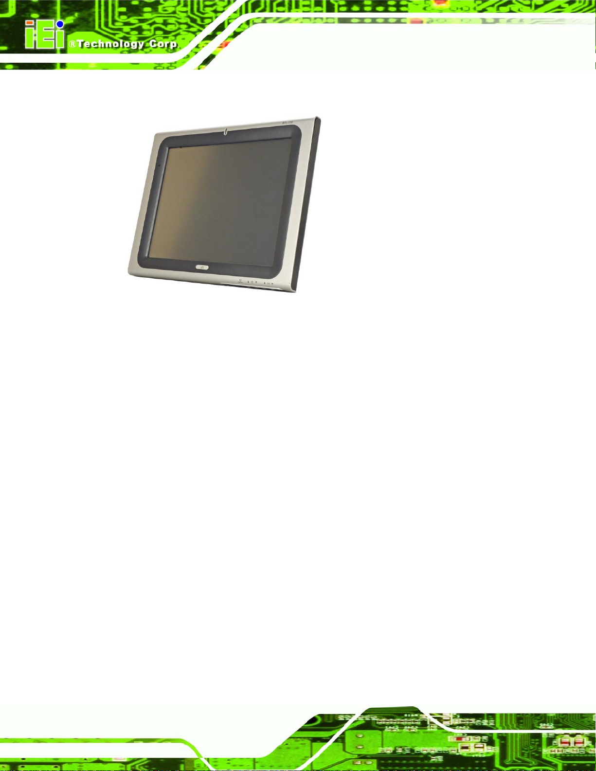
1.1 General Overview
Figure 1-1: AFOLUX 9652 Series Touch Panel PC
The AFL-15C-9652, AFL-17C-9652 and AFL-19C-9652 (AFL-9652 series) are Intel®
Core™2 Duo or Intel® Celeron® M powered flat panel PCs with a rich variety of functions
and peripherals. Both AFL-9652 models are designed for easy and simplified integration in
to multiple applications.
An Intel® GME965 graphics memory controller hub (GMCH) coupled with an Intel®
ICH8M input/output controller hub ensures optimal memory, graphics, and peripheral I/O
support. The system comes with 1.0 GB or 2.0 GB of preinstalled DDR2 SDRAM and
supports a maximum of 4.0 GB of DDR2 SDRAM ensuring smooth data throughputs with
reduced bottlenecks and fast system access.
Two serial ports and four external USB 2.0 ports ensure simplified connectivity to a variety
of external peripheral devices. A VGA connector enables connectivity to other monitors.
802.11 a/b/g/n Wi-Fi capabilities and two RJ-45 Ethernet connectors ensure smooth
connection of the system to an external LAN.
Page 2
Page 21
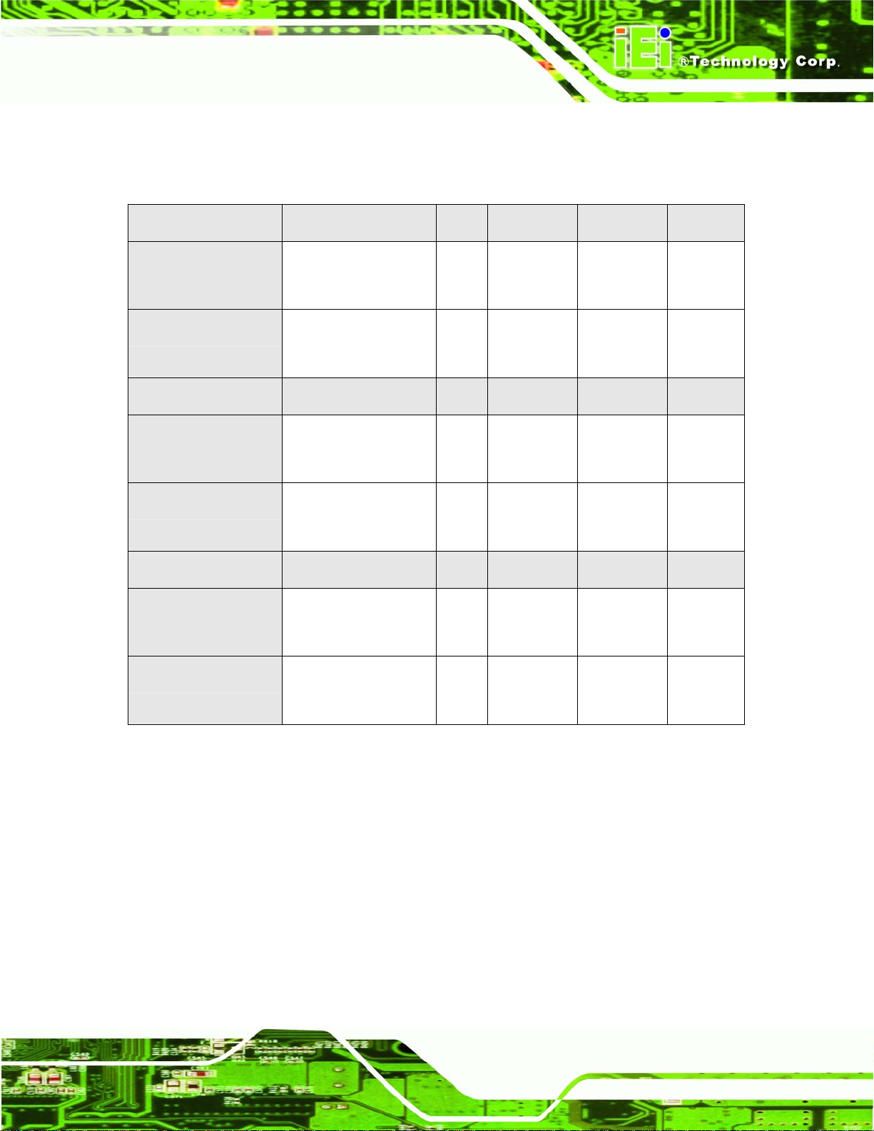
1.1.1 Model Variations
The models of AFL-9652 series are listed in Table 1-1.
AFL-15C-9652 CPU LCD Brightness Memory Wireless
-CM550/WT-R/1GB
2.0 GHz Intel®
15” 350 cd/m2 1 GB DDR2 Yes
Celeron® M (550)
-T7500/WT-R/2GB
2.2 GHz Intel® Core™2
15” 350 cd/m2 2 GB DDR2 Yes
Duo (T7500)
AFL-17C-9652 CPU LCD Brightness Memory Wireless
-CM550/WT-R/1GB
2.0 GHz Intel®
17” 300 cd/m2 1 GB DDR2 Yes
Celeron® M (550)
-T7500/WT-R/2GB
2.2 GHz Intel® Core™2
17” 300 cd/m2 2 GB DDR2 Yes
Duo (T7500)
AFL-19C-9652 CPU LCD Brightness Memory Wireless
-CM550/WT-R/1GB
2.0 GHz Intel®
19” 300 cd/m2 1 GB DDR2 Yes
Celeron® M (550)
-T7500/WT-R/2GB
2.2 GHz Intel® Core™2
Duo (T7500)
Table 1-1: Model Variations
1.1.2 Standard Features
Some of the standard features of the AFL-9652 series flat panel PC include:
Rugged mechanism design with ABS/PC case
IP 64 dustproof and waterproof front panel
1.0 GB / 2.0 GB DDR2 memory
802.11 a/b/g/n Wireless LAN
eSATA port
19” 300 cd/m2 2 GB DDR2 Yes
Page 3
Page 22

Dual 10/100/1000 Mbps Ethernet support
Bluetooth connectivity supported
Optional GPRS and HSDPA interfaces supported
Supports Intel® Active Management Technology (AMT) 2.5
Simplified installation process
RoHS compliance
1.2 External Overview
The AFL-9652 series is a flat panel PC. The monitor and all internal components are
enclosed in an aluminum chassis. An ABS/PC plastic cover surrounds the aluminum
chassis. VESA compliant screw holes in the rear panel allow the AFOLUX to be attached
to any VESA compliant mounting. The access panel at the bottom of the AFOLUX gives
access to a VGA port, four USB ports, an eSATA port, two Ethernet ports, a
RS-232/422/485 port, a RS-232 port, an audio jack, power input and power switch.
1.2.1 Front Panel
The front side of the AFL-9652 series is a flat panel TFT LCD screen surrounded by an
ABS/PC plastic frame.
Figure 1-2: Front View
Page 4
Page 23

1.2.2 Rear Panel
The rear panel provides access to retention screw holes that support the wall mounting.
Refer to
Figure 1-3.
Figure 1-3: AFL-9652 Rear View
1.2.3 Bottom Panel
The bottom panel of the AFL-9652 series has the following I/O interfaces (Figure 1-4):
1 x 12 V DC power input connector
1 x Audio jack
1 x AT/ATX switch
1 x eSATA port
1 x Power switch
1 x Reset button
1 x RS-232 serial port connector
1 x RS-232/422/485 serial port connector
2 x RJ-45 10/100/1000Mbps Ethernet connectors
4 x USB 2.0 connectors
1 x VGA port
Page 5
Page 24

Figure 1-4: AFL-9652 Bottom View
1.3 Internal Overview
The AFL-9652 includes the following parts inside the aluminum internal cover.
1.0 GB DDR2 SO-DIMM
Antennas
Backlight inverter
Bluetooth module
CompactFlash® disk (optional)
GPRS module (optional)
Hard drive (optional)
Two speakers
Wireless LAN card
Page 6
Page 25

Figure 1-5: Internal Overview
1.4 Specifications
1.4.1 Preinstalled Hardware Components
The AFL-9652 series flat panel PC has the following preinstalled components:
1 x Motherboard
1 x TFT LCD screen
1 x Touch screen panel
1 x Inverter
1 x Wireless LAN module
2 x DDR2 memory modules
1 x Bluetooth module
1 x AT/ATX switch
2 x Speakers
The technical specifications for the system, and some of these components, are shown in
the sections below.
Page 7
Page 26
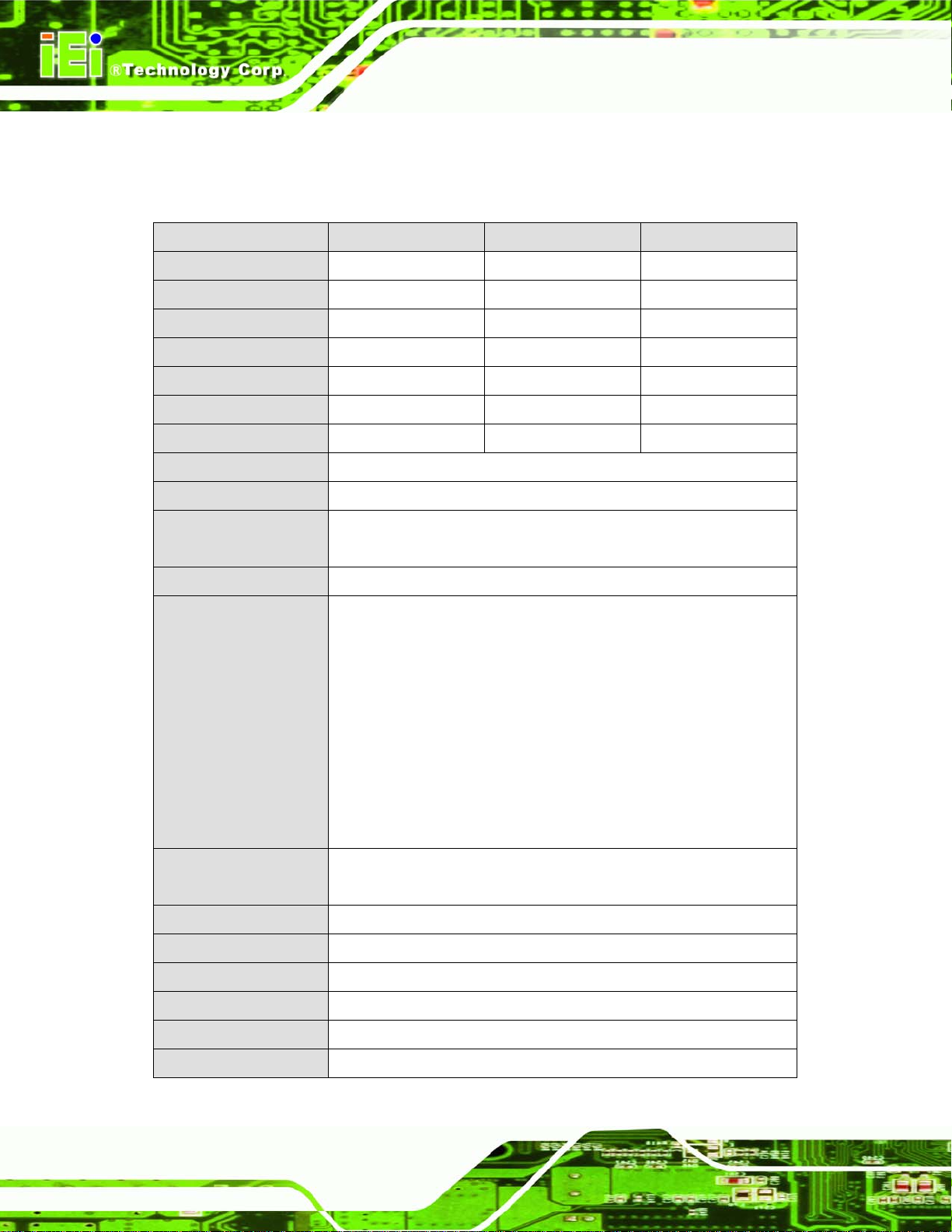
1.4.2 System Specifications
The technical specifications for the AFL-9652 series systems are listed in Table 1-2.
SPECIFICATION 15 inch 17 inch 19 inch
LCD Size 15” 17” 19”
Max Resolution 1024 x 768 1280 x 1024 1280 x 1024
Brightness (cd/m2) 350 300 300
Contrast Ratio 700:1 800:1 1000:1
LCD Color 262K 16.7M 16.7M
Pixel Pitch (mm) 0.297 (H) x 0.297 (V)
Viewing Angle (H-V) 140 / 125 160 / 160 178 / 178
Backlight MTBF 50,000 hours
SBC Model AFLMB-9652
CPU 2.0 GHz Intel® Celeron M 550 CPU or
2.20 GHz Intel® Core™2 Duo T7500 CPU
Memory One or two 200-pin 1.0 GB dual-channel DDR2 SO-DIMM
I/O Ports 1 x eSATA port
2 x RS-232
1 x RS-232/422/485
2 x RJ-45
4 x USB 2.0
1 x Power switch
1 x Reset button
1 x VGA port
1 x Audio
0.264 (H) x 0.264 (V) 0.294 (H) x 0.294 (V)
Storage 1 x 2.5” SATA
1 x CompactFlash® Type I/II
Speakers 2 x 3 W AMP
Expansion 1 x PCIe Mini Wireless LAN Module
Construction Material ABS + PC Plastic front frame
LED Functions 1 x Power on/off LED
Mounting VESA MIS-D mount for panel, wall, rack, stand and arm mounting
Front Panel Color Silver and black
Page 8
Page 27
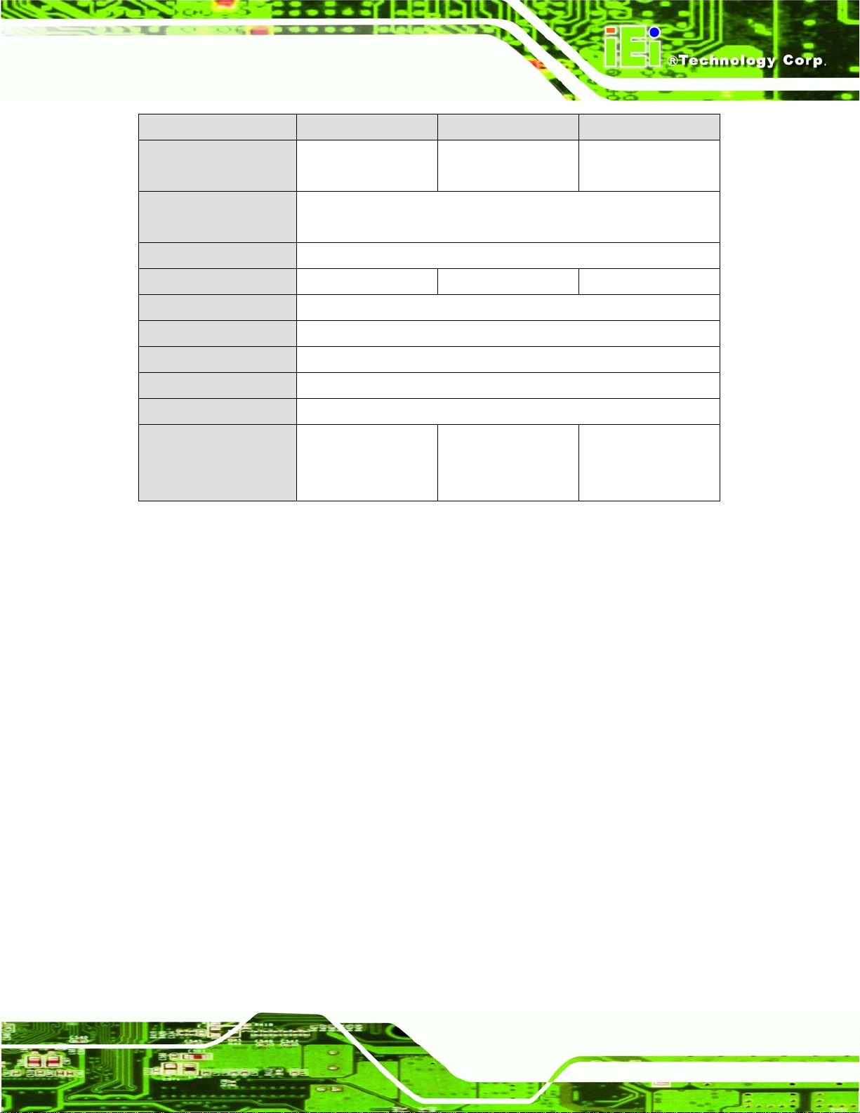
SPECIFICATION 15 inch 17 inch 19 inch
Dimensions (W x H x
D) (mm)
Operating
Temperature
Storage Temperature -20°C ~ 60°C
Net Weight 5.8 kg 5.8 kg 6.2 kg
IP Level IP 64
EMC CE, FCC, CCC
Safety UL, CB
Touch Screen Resistive Type 5 Wire (touch controller IC is on board)
Power Input 12 V DC
Power Consumption
(Intel® T7500, 2 GB
memory, 80 GB HDD)
393 x 308 x 74 428 x 350 x 76 470 x 383 x 78
0°C ~ 40°C (0°C ~ 45°C with CompactFlash® or SSD HDD)
80 W 86 W 88 W
Table 1-2: AFL-9652 series System Specifications
Page 9
Page 28

Chapter
2
2 Specifications
Page 10
Page 29
2.1 Dimensions
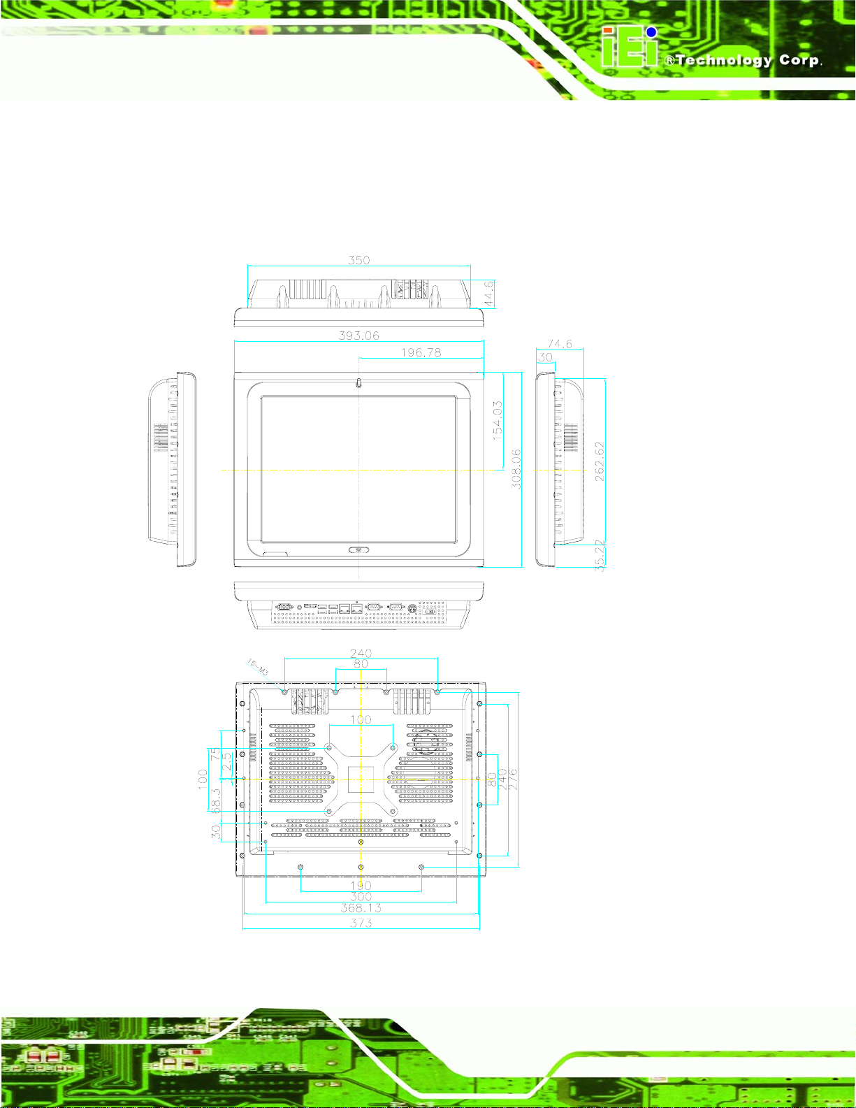
2.1.1 AFL-15C-9652 Dimensions
The dimensions of the AFL-15C-9652 flat panel PC are shown in Figure 2-1 below.
Figure 2-1: AFL-15C-9652 Dimensions (units in mm)
Page 11
Page 30
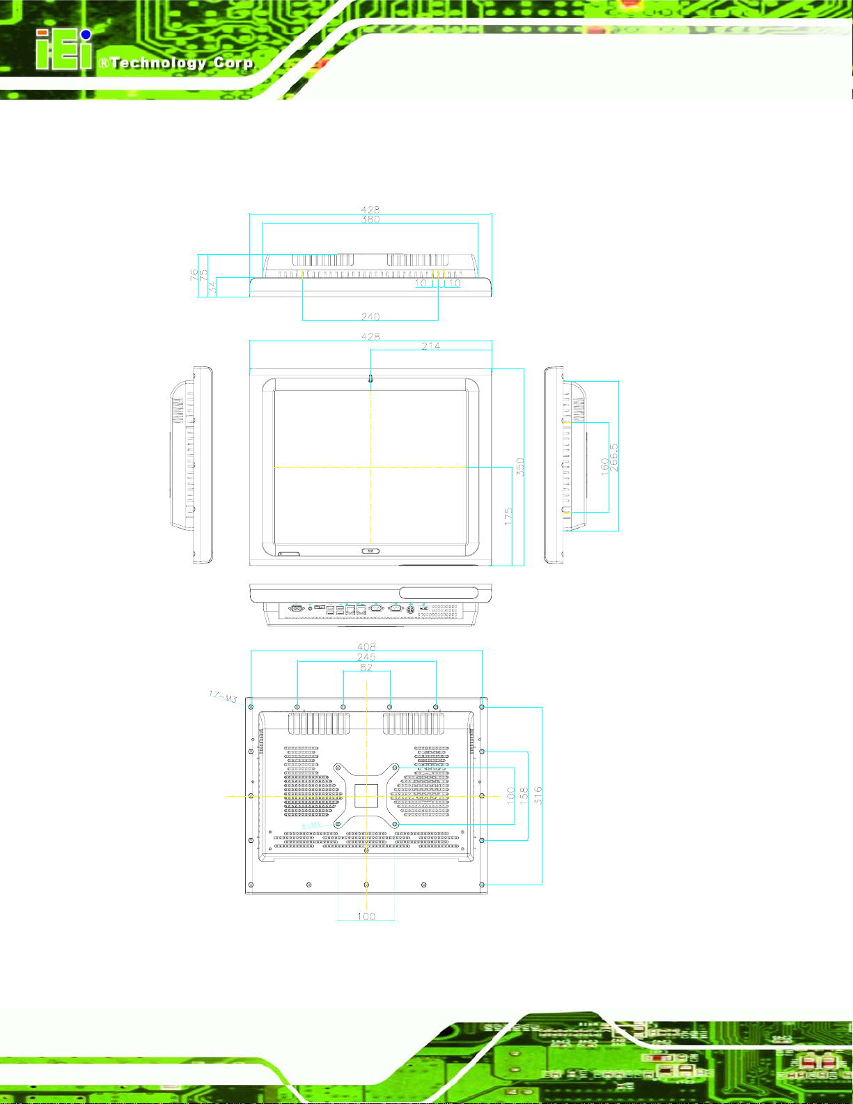
2.1.2 AFL-17C-9652 Dimensions
The dimensions of the AFL-17C-9652 flat panel PC are shown in Figure 2-2 below.
e SATA
Figure 2-2: AFL-17C-9652 Dimensions (units in mm)
Page 12
Page 31
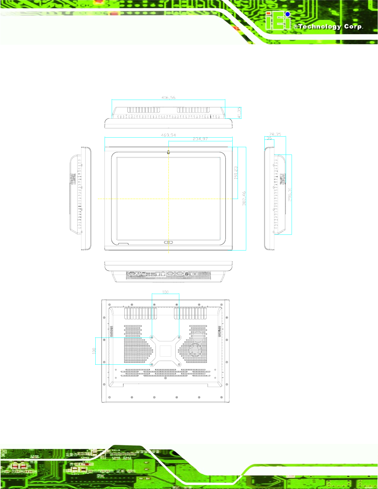
2.1.3 AFL-19C-9652 Dimensions
The dimensions of the AFL-19C-9652 flat panel PC are shown in Figure 2-2 below.
Figure 2-3: AFL-19C-9652 Dimensions (units in mm)
Page 13
Page 32
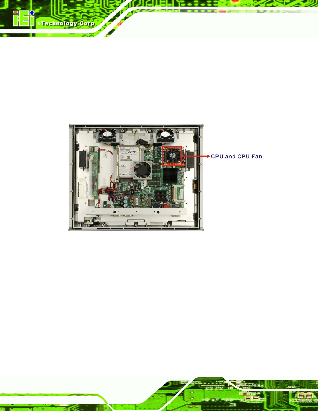
2.2 Intel® Desk-Top Processor Support
A T7500 Intel® Socket P Core™2 Duo or a 550 Intel® Socket P Celeron® M processor is
installed in the system. TheT7500 Intel® Core™2 Duo processor has a CPU speed of
2.2 GHz, a 800 MHz front side bus (FSB) and a 4.0 MB L2 cache. The 550 Intel®
Celeron® M processor has a CPU speed of 2.0 GHz, a 533 MHz front side bus (FSB) and
a 1.0 MB L2 cache. The processor is shown in
Figure 2-4 below.
Figure 2-4: CPU and CPU Fan
T7500 Intel® Socket P Core™2 Duo desktop processor supports the following Intel®
Page 14
features:
Dual Core
Intel® Wide Dynamic Execution
Intel® Intelligent Power Capability
Intel® Smart Memory Access
Intel® Advanced Smart Cache
Page 33

2.3 Motherboard Components
The following sections describe some of the features on the motherboard.
2.3.1 Memory Support
2.3.1.1 Installed Memory
Two 200-pin 1.0 GB or one 1.0 GB DDR2 SDRAM SO-DIMM are installed in the
AFL-9652 and controlled by the Intel® GME965 GMCH installed on the internal
motherboard.
Figure 2-5: Memory Module and Memory Socket
2.3.1.2 Additional Memory
The Intel® GME965 is capable of supporting two 200-pin 2.0 GB (max.) 400 MHz DDR2
SDRAM SO-DIMM (system max. 4.0 GB). If additional memory is required, please contact
an IEI sales representative and discuss the necessary system requirement.
2.3.2 Storage Capacity
The AFL-9652 comes with a SATA hard disk drive bay for a 2.5” HDD. The system can
also support an easily installed CompactFlash® Type II (CF Type II) memory disk.
Page 15
Page 34
2.4 External Peripheral Interface Connectors
The following section describes the external peripheral interface connectors on the rear
panel of the subsystem.
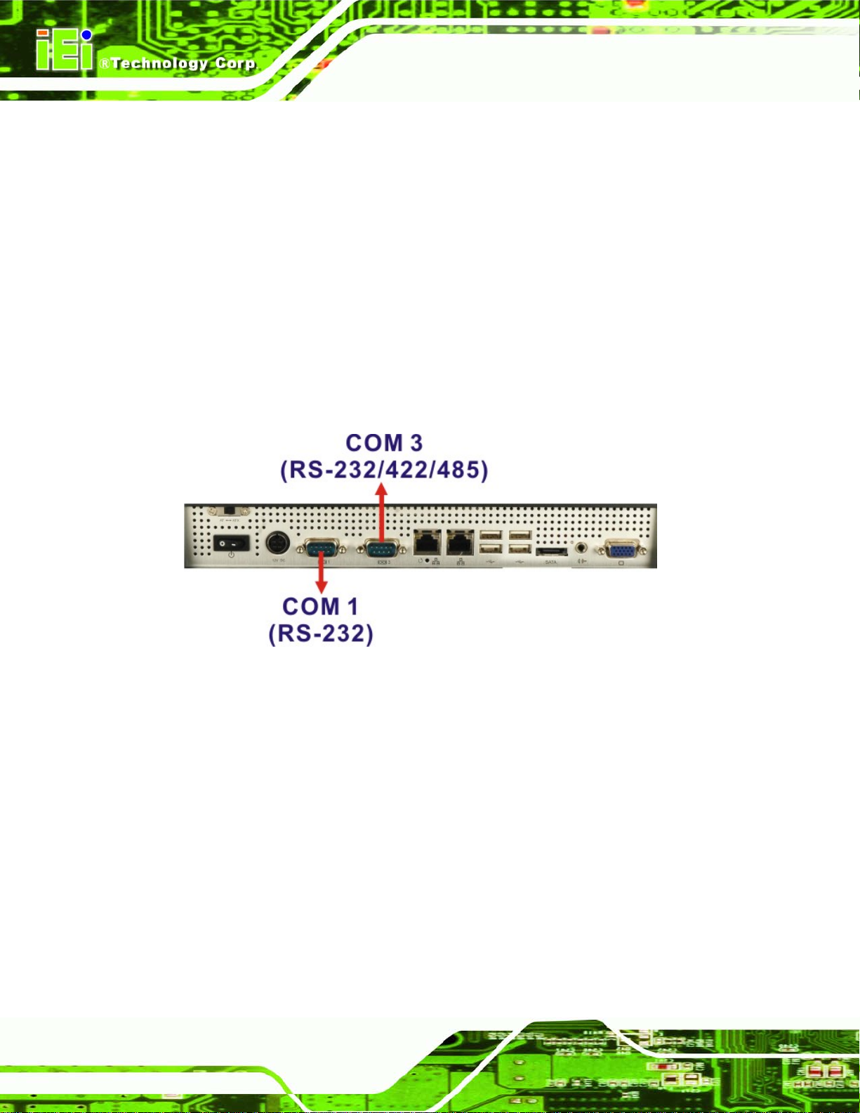
2.4.1 Serial Port Connectors
The AFL-9652 has two serial ports. The COM1 serial port is a RS-232 only port. The
COM3 serial port can be configured as a RS-232, RS-422 or an RS-485 serial port. Pin 9
on all ports can be set as the normal ring (RI) signal or can be designated as a 5 V or 12 V
power supply. The two serial ports (COM1 and COM3) are interfaced to the ITE IT8712
super IO, through the low pin count (LPC) bus to the ICH8M Southbridge.
Figure 2-6: COM Ports
There is one additional on-board serial port (COM2) which is connected to the touch
screen panel.
2.4.2 LAN Connectivity
The AFL-9652 series has two GbE connectors on the bottom panel. One of the external
RJ-45 Ethernet LAN connectors is interfaced to an Intel® 82566MM Gigabit LAN connect
device from the ICH8M Southbridge. The other RJ-45 Ethernet LAN connector is
interfaced directly to an Intel® 82573L PCIe GbE controller.
Page 16
Page 35

Figure 2-7: RJ-45 Ethernet Connectors
2.4.3 External USB Connectors
There are four USB 2.0 connectors on the bottom panel of the AFL-9652. All the USB 2.0
connectors are interfaced directly to the USB controllers on the ICH8M Southbridge. The
USB connectors are all fully compliant with USB specification Revision 2.0 and USB
specification Revision 1.1 and can be interfaced to both USB 1.1 and USB 2.0 compliant
devices.
Figure 2-8: External USB Ports
2.4.4 eSATA Connectivity
An external SATA connector on the bottom panel interfaces to ICH8M Southbridge on the
motherboard that connects through the serial ATA bus. The external SATA connector
supports one external SATA drive.
Figure 2-9: eSATA Connector
Page 17
Page 36

2.5 AFOLUX AFL-9652 Front Side
2.5.1 Monitor
A LCD screen is installed on the front of the AFL-9652 series and connected to the LVDS
connector on the motherboard. The screen is shown in
Figure 2-10 below.
Figure 2-10: LCD Screen
2.5.2 Touch-Screen Module
A controller for the 5-wire resistive touch screen is installed on the motherboard. The
sensitive touch screen is accurate, reliable and durable.
2.6 Graphics
2.6.1 Intel® GME965 Integrated Graphics Media Accelerator 950
The Intel® GME965 has the mobile Intel® Graphics Media Accelerator (GMA) X3100
integrated into the chipset and interfaced to the VGA connector. The Intel® GMA X3100,
with an integrated 300 MHz RAMDAC and hot plug CRT support, supports analog CRT
monitors up to QXGA.
Page 18
Page 37

Figure 2-11: VGA Connector
2.6.2 Dual-Display
The system supports dual display capabilities. An additional monitor can be connected to
the AFL-9652 series through the VGA connector described above.
2.7 Audio
2.7.1 High Definition Audio Controller
The integrated High Definition Audio compliant audio controller on the Intel® ICH8M
Southbridge is integrated to a RealTek ALC262 audio codec. The RealTek ALC262 is
connected to the external audio jack, which is then connected to compliant audio devices.
The RealTek ALC262 is a four-channel High Definition Audio codec with two 24-bit stereo
DACs and three 20-bit stereo ADCs. The codec and the audio connector are shown in
Figure 2-12.
Figure 2-12: Audio Jack
2.7.2 Stereo Speakers
Two stereo speakers on the both sides of the AFL-9652 are interfaced to the system
through a Philips TDA1517P integrated 3 W dual output amplifier.
Page 19
Page 38

Figure 2-13: Stereo Speakers
2.8 System Power
2.8.1 Power Mode
The system can be run in the AT power mode or the ATX power mode. Both these power
modes are described below.
2.8.1.1 ATX Power Mode (Default)
With the ATX mode selected, the AFOLUX AFL-9652 panel PC goes in a standby mode
when it is turned off. The panel PC can be easily turned on via network or a power switch
in standby mode. Remote power control is perfect for advertising applications since the
broadcasting time for each panel PC can be set individually and controlled remotely. Other
possible application includes
Security surveillance
Point-of-Sale (POS)
Advertising terminal
Page 20
Page 39
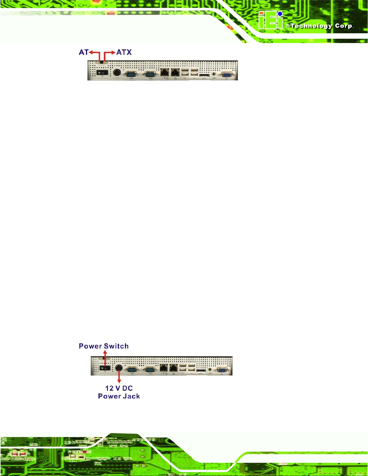
Figure 2-14: Power Connector
2.8.1.2 AT Power Mode
With the AT mode selected, the power is controlled by a central power unit rather than a
power switch. The AFOLUX AFL-9652 panel PC turns on automatically when the power is
connected. The AT mode benefits a production line to control multiple panel PCs from a
central management center and other applications including:
ATM
Self-service kiosk
Plant environment monitoring system
Factory automation platform
Manufacturing shop flow
2.8.2 Power Adapter
The system is shipped with a 90 V to 264 V AC power adapter that has a maximum power
output of 96 W. The power adapter has a 12 V DC output connectors.
2.8.3 Power Connector
The power connector is located on the bottom panel interface panel. A 12 V DC input
connector is a standard 4-pin power connector shown in
Figure 2-15 below.
Figure 2-15: Power Connector
Page 21
Page 40

2.9 Wireless Connections
The following section describes the wireless modules on the circuit.
2.9.1 USB Bluetooth Module
An integrated Bluetooth module is connected to ICH8M chipset through the USB bus. The
AFL-9652 Bluetooth module enables wireless communications between the AFL-9652
and various peripheral devices through a Bluetooth network. The peripheral devices may
include:
Headsets
Barcode readers
PDA
Printers
Cell phones
Keyboard and mouse
The Bluetooth module is shown in
the Bluetooth module are listed in the Appendix.
Figure 2-16 below and the technical specifications of
Page 22
Figure 2-16: Bluetooth Module
Page 41
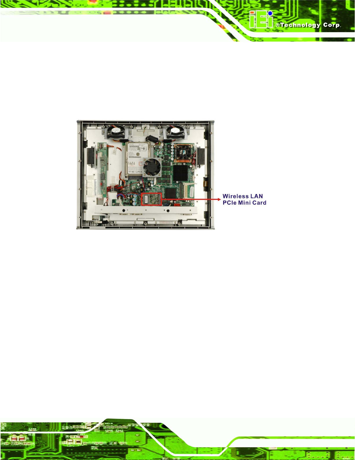
2.9.2 Wireless Ethernet
An integrated 802.11 a/b/g/n wireless LAN module and PIFA antenna on the AFL-9652
series ensure an uninterrupted wireless connection. PIFA antennas can receive
high-quality, uniform signals in any location from all directions without any signal
degradation or impedance and are the most efficient antennas on the market.
Figure 2-17: Wireless LAN Module
2.10 Optional Modules
The following sections describe the optional module available to the user.
2.10.1 HSDPA Module (Optional)
An optional HSDPA module can be integrated into the AFL-9652 and provide the 3.5G
mobile connectivity. The HSDPA module is one of the OEM options for the AFL-9652
series. The technical specifications of the HSDPA module are listed in the Appendix.
2.10.2 GPRS Module (Optional)
An optional GPRS module can be integrated into the AFL-9652 and provide the 2.5G
mobile connectivity. The GPRS module is one of the OEM options for the AFL-9652 series.
The technical specifications of the GPRS module are listed in the Appendix.
Page 23
Page 42

Chapter
3
3 Unpacking
Page 24
Page 43
3.1 Unpacking
To unpack the flat panel PC, follow the steps below:
WARNING!
The front side LCD screen has a protective plastic cover stuck to the
screen. Only remove the plastic cover after the flat panel PC has been
properly installed. This ensures the screen is protected during the
installation process.
Step 1: Use box cutters, a knife or a sharp pair of scissors that seals the top side of the
external (second) box.
Step 2: Open the external (second) box.
Step 3: Use box cutters, a knife or a sharp pair of scissors that seals the top side of the
internal (first) box.
Step 4: Lift the monitor out of the boxes.
Step 5: Remove both polystyrene ends, one from each side.
Step 6: Pull the plastic cover off the flat panel PC.
Step 7: Make sure all the components listed in the packing list are present. Step 0:
3.1.1 Packing List
The AFL-9652 flat panel PC is shipped with the following components:
Page 25
Page 44

Quantity Item Image
Standard
1 AFL-9652 series panel PC
1 Power adapter
1 Power cord
1 User manual CD and driver CD
1 Touch pen
1 eSATA cable
1 Screw kit
Optional
Wall mounting kit
Page 26
Panel mounting kit
Page 45

Quantity Item Image
128 MB CompactFlash® card with Windows CE 5.0
pre-installed
128 MB CompactFlash® card with Windows CE 6.0
pre-installed
1 GB CompactFlash® card with Windows XPE
pre-installed
If any of these items are missing or damaged, contact the distributor or sales
representative immediately.
Page 27
Page 46

Chapter
4
4 Installation
Page 28
Page 47

4.1 Anti-static Precautions
WARNING:
Failure to take ESD precautions during the maintenance of the
AFL-9652 may result in permanent damage to the AFL-9652 and
severe injury to the user.
Electrostatic discharge (ESD) can cause serious damage to electronic components,
including the AFL-9652. Dry climates are especially susceptible to ESD. It is therefore
critical that whenever the AFL-9652 is accessed internally, or any other electrical
component is handled, the following anti-static precautions are strictly adhered to.
Wear an anti-static wristband: - Wearing a simple anti-static wristband can
help to prevent ESD from damaging the board.
Self-grounding:- Before handling the board touch any grounded conducting
material. During the time the board is handled, frequently touch any
conducting materials that are connected to the ground.
Use an anti-static pad: - When configuring the AFL-9652, place it on an
antic-static pad. This reduces the possibility of ESD damaging the AFL-9652.
Only handle the edges of the PCB: - When handling the PCB, hold the PCB
by the edges.
4.2 Installation Precautions
When installing the flat panel PC, please follow the precautions listed below:
Power turned off: When installing the flat panel PC, make sure the power is
off. Failing to turn off the power may cause severe injury to the body and/or
damage to the system.
Certified Engineers: Only certified engineers should install and modify
onboard functionalities.
Mounting: The flat panel PC is a heavy device. When mounting the system
onto a rack, panel, wall or arm please make sure that at least two people are
Page 29
Page 48

assisting with the procedure.
Anti-static Discharge: If a user open the rear panel of the flat panel PC, to
configure the jumpers or plug in added peripheral devices, ground themselves
first and wear and anti-static wristband.
4.3 Preinstalled Components
The following components are all preinstalled.
Motherboard
Backlight inverter
TFT LCD screen
DDR2 memory modules
Resistive type touch screen panel
Wireless LAN module
Bluetooth module
AT/ATX power switch
Preinstalled OEM customizations may include the following.
Different DDR2 memory modules
2.5” SATA hard disk drive
GPRS / HSDPA module
Installation of some of the components is described in the following sections.
4.4 Installation and Configuration Steps
The following installation steps must be followed.
Step 1: Unpack the flat panel PC
Step 2: Install the CompactFlash® card (optional)
Page 30
Step 3: Install the GPRS (optional)
Step 4: Install the hard drive (optional)
Step 5: Mount the flat panel PC
Page 49

Step 6: Connect peripheral devices
Step 7: Configure the systemStep 0:
4.5 CF Card Installation
The AFL-9652 series has one CompactFlash® Type I/II slot inside the left side panel. To
install the CF card, follow the instructions below.
Step 1: Remove the retention screws (
Figure 4-1) and lift the cover off the flat panel PC.
Figure 4-1: Back Cover Retention Screws
Step 2: Locate the CF slot. Align the CF card with the guides on the slot (
Figure 4-2).
Figure 4-2: CF Card Location
Page 31
Page 50

Step 3: Insert a CF card into the slot (Figure 4-3).
Figure 4-3: CF Card Installation
Step 4: Replace the plastic back cover and fasten the retention screws. Step 0:
WARNING:
Over-tightening back cover screws will crack the plastic frame.
Maximum torque for cover screws is 5 kg-cm (0.36 lb-ft/0.49 Nm).
4.6 HDD Installation
To install the hard drive, please follow the steps below:
Step 1: Disconnect the system power cable.
Step 2: Remove the plastic back cover. See Section
Step 3: Remove the 10 round head retention screws and two flat head retention screws
securing the internal aluminum cover (
4.5 above.
Figure 4-4).
Page 32
Page 51

Figure 4-4: Aluminum Back Cover Retention Screws
Step 4: Lift the aluminum cover to remove.
Step 5: Remove the system fan on the top of the HDD bracket by removing the two
retention screws (
Figure 4-5).
Figure 4-5: System Fan Retention Screws
Step 6: Remove the remaining two HDD bracket retention screws (
the HDD bracket off the panel PC.
Figure 4-6) and lift
Page 33
Page 52

Figure 4-6: AFL-9652 Hard Drive Bracket Retention Screws
Step 7: Attach the hard drive to the hard drive bracket. To do this, align the four retention
screw holes on the hard drive with the screw holes on the hard drive bracket.
Fasten four flat head retention screws to secure the hard drive to the bracket
Figure 4-7).
(
Figure 4-7: Hard Drive Retention Screws
Step 8: Reinstall the hard drive bracket. Slide the hard drive bracket into its original
position, making sure the SATA connectors on the hard drive connect with the
Page 34
SATA connectors on the motherboard.
Step 9: Fasten the hard drive bracket screws (
Figure 4-8).
Page 53

Figure 4-8: Hard Drive Installed
Step 10: Replace the aluminum back cover to the chassis.
Step 11: Replace the plastic back cover.Step 0:
4.7 AT/ATX Mode Selection
AT and ATX power modes can both be used on the AFL-9652 series. The selection is
made through an AT/ATX switch on the bottom panel (
ATX mode, follow the steps below.
Step 1: Locate the AT/ATX switch on the bottom panel (
Figure 4-9: AT/ATX Switch Location
Step 2: The system is set to ATX mode by default. To change to the AT mode, just adjust
Figure 4-9). To select AT mode or
Figure 4-9).
the AT/ATX switch to AT mode.
Step 3: To switch from AT mode to ATX mode, please load BIOS default or clear
CMOS first. Then adjust the switch to ATX mode. Step 0:
Page 35
Page 54

NOTE:
To load BIOS default, please use the Load Optimal Defaults option of the
Exit menu in the BIOS (refer to Section
optimal default values for each of the parameters on the Setup menus. F9
key can be used for this operation.
4.8 Mounting the System
WARNING!
When mounting the flat panel PC onto an arm, onto the wall or onto a
panel, it is better to have more than one person to help with the installation
to make sure the panel PC does not fall down and get damaged.
The four methods of mounting the AFL-9652 series are listed below.
6.8 on page 103) to load the
Wall mounting
Panel mounting
Arm mounting
Rack mounting
The four mounting methods are described below.
4.8.1 Wall Mounting
To mount the flat panel PC onto the wall, please follow the steps below.
Step 1: Select the location on the wall for the wall-mounting bracket.
Page 36
Page 55
Step 2: Carefully mark the locations of the four brackets screw holes on the wall.
Step 3: Drill four pilot holes at the marked locations on the wall for the bracket retention
screws.
Step 4: Align the wall-mounting bracket screw holes with the pilot holes.
Step 5: Secure the mounting-bracket to the wall by inserting the retention screws into
the four pilot holes and tightening them (
Figure 4-10).
Figure 4-10: Wall-mounting Bracket
Step 6: Insert the four monitor mounting screws provided in the wall mounting kit into the
four screw holes on the real panel of the flat panel PC and tighten until the screw
shank is secured against the rear panel (
Step 7: Align the mounting screws on the monitor rear panel with the mounting holes on
the bracket.
Step 8: Carefully insert the screws through the holes and gently pull the monitor
downwards until the monitor rests securely in the slotted holes (
Ensure that all four of the mounting screws fit snuggly into their respective
slotted holes.
Figure 4-11).
Figure 4-11).
Page 37
Page 56

Figure 4-11: Chassis Support Screws
NOTE:
In the diagram below the bracket is already installed on the wall.
Step 9: Secure the panel PC by fastening the retention screw of the wall-mounting
bracket. (
Figure 4-12).Step 0:
Page 38
Page 57

Figure 4-12: Secure the Panel PC
4.8.2 Panel Mounting
To mount the AFL-9652 series flat panel PC into a panel, please follow the steps below.
Step 1: Select the position on the panel to mount the flat panel PC.
Step 2: Cut out a section from the panel that corresponds to the rear panel dimensions
of the flat panel PC. Take care that the panel section that is cut out is smaller
than the overall size of the metal frame that surrounds the flat panel PC but just
large enough for the rear panel of the flat panel PC to fit through (
Figure 4-14 and Figure 4-15).
Figure 4-13,
Page 39
Page 58
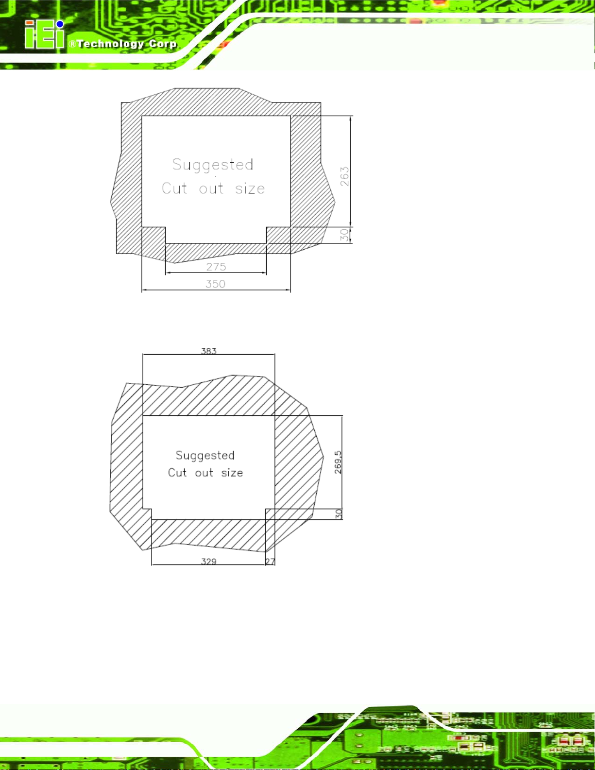
Figure 4-13: AFL-15C-9652 Cutout Dimensions (units in mm)
Figure 4-14: AFL-17C-9652 Cutout Dimensions (units in mm)
Page 40
Page 59
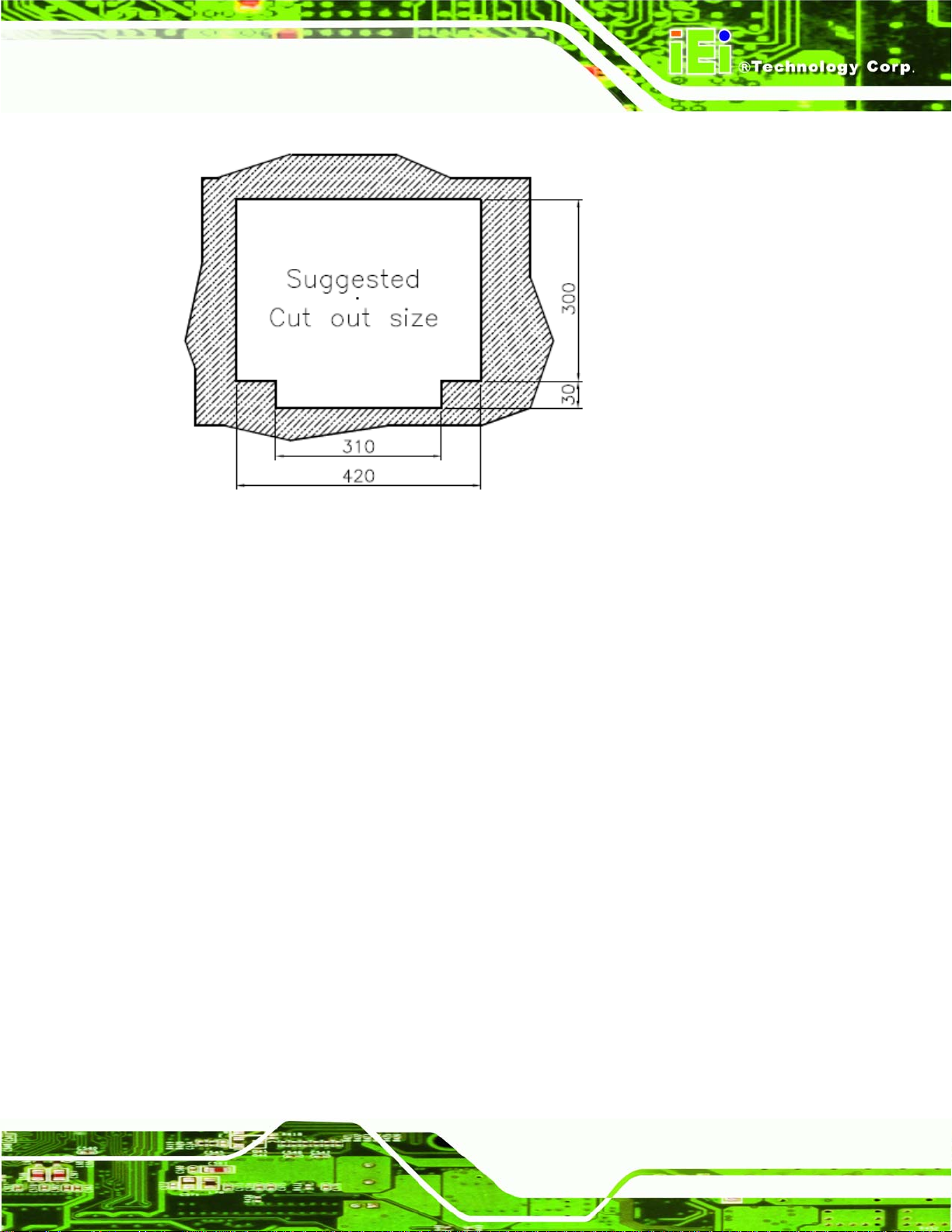
Figure 4-15: AFL-19C-9652 Cutout Dimensions (units in mm)
Step 3: Slide the flat panel PC through the hole until the plastic frame is flush against the
panel.
Step 4: Insert the panel mounting clamps into the pre-formed holes along the edges of
the chassis, behind the plastic frame.
Step 5: Tighten the screws that pass through the panel mounting clamps until the plastic
caps at the front of all the screws are firmly secured to the panel (
Step 0:
Figure 4-16).
Page 41
Page 60

Figure 4-16: Tighten the Panel Mounting Clamp Screws
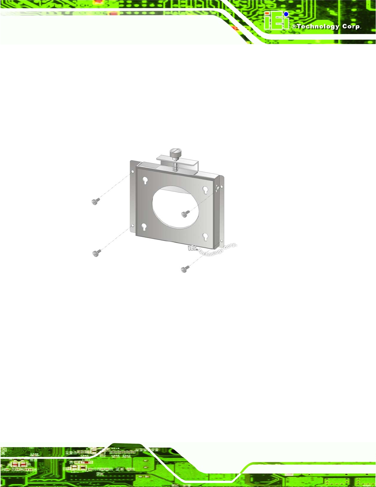
4.8.3 Arm Mounting
The AFL-9652 series is VESA (Video Electronics Standards Association) compliant and
can be mounted on an arm with a 100mm interface pad. To mount the AFL-9652 series on
an arm, please follow the steps below.
Step 1: The arm is a separately purchased item. Please correctly mount the arm onto
the surface it uses as a base. To do this, refer to the installation documentation
that came with the mounting arm.
NOTE:
When purchasing the arm please ensure that it is VESA compliant and that
Page 42
the arm has a 100 mm interface pad. If the mounting arm is not VESA
compliant it cannot be used to support the AFL-9652 series flat panel PC.
Page 61

Step 2: Once the mounting arm has been firmly attached to the surface, lift the flat panel
PC onto the interface pad of the mounting arm.
Step 3: Align the retention screw holes on the mounting arm interface with those in the
flat panel PC, as shown in
Figure 4-17.
Figure 4-17: Arm Mounting Retention Screw Holes
Step 4: Secure the flat panel PC to the interface pad by inserting four retention screws
through the bottom of the mounting arm interface pad and into the flat panel PC.
Step 0:
4.8.4 Cabinet and Rack Installation
The AFL-9652 series flat panel PC can be installed into a cabinet or rack. The installation
procedures are similar to the panel mounting installation. To do this, please follow the
steps below:
Page 43
Page 62
NOTE:
When purchasing the cabinet/rack installation bracket, make sure it is
compatible with both the AFL-9652 series flat panel PC and the
rack/cabinet into which the AFL-9652 series is installed.
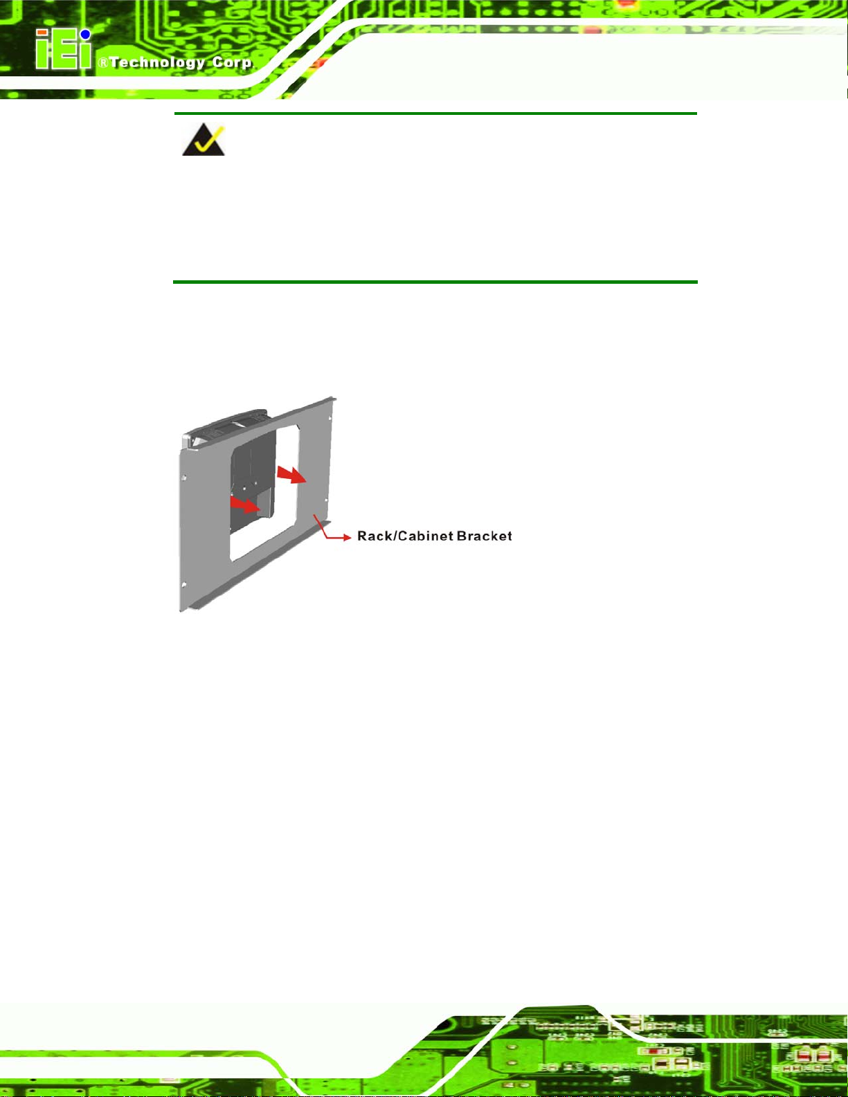
Step 1: Slide the rear of the AFL-9652 series flat panel PC through the rack/cabinet
bracket until the plastic frame is flush against the front of the bracket (
4-18).
Figure
Figure 4-18: The Rack/Cabinet Bracket
Step 2: Insert the rack mounting clamps into the pre-formed holes along the edges of
the flat panel PC, behind the ABS/PC plastic frame.
Page 44
Step 3: Tighten the screws that pass through the rack mounting clamps until the plastic
caps at the front of all the screws are firmly secured to the bracket (
Figure 4-19).
Page 63
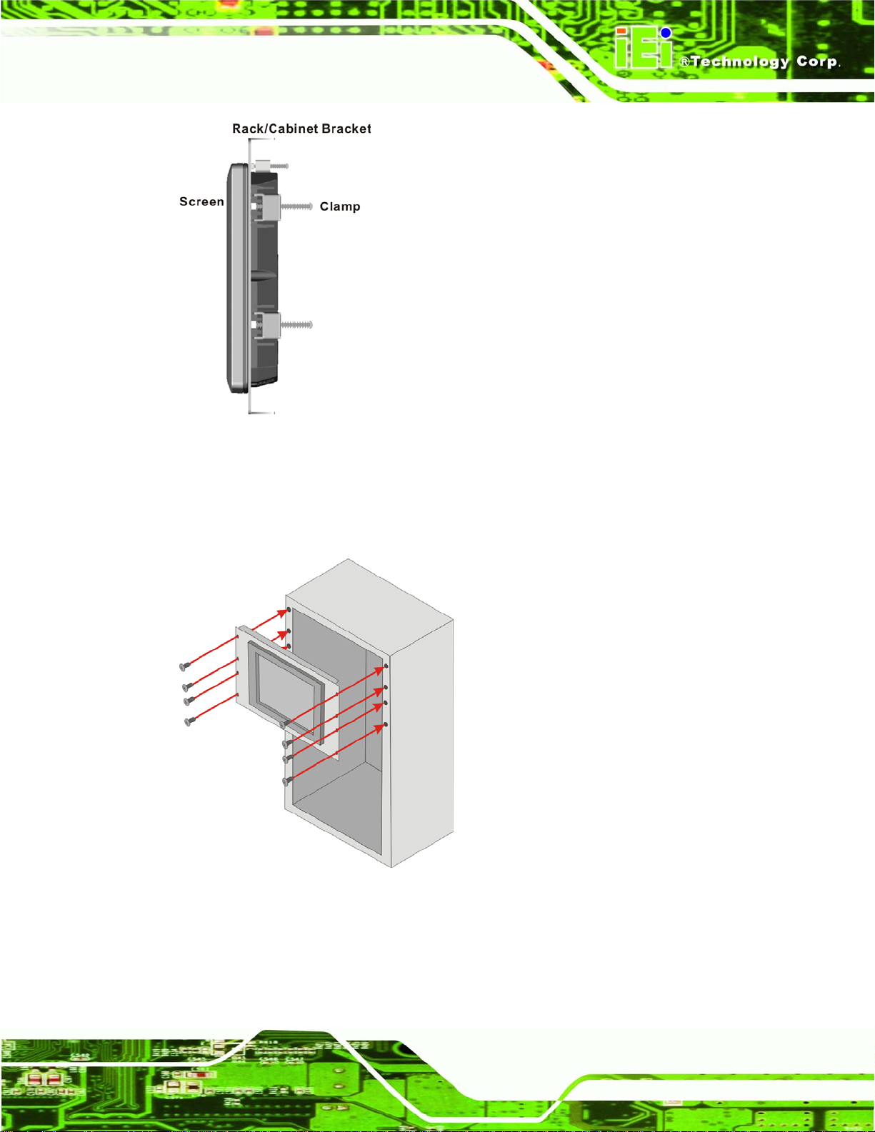
Figure 4-19: Secure the Rack/Cabinet Bracket
Step 4: Slide the flat panel PC with the attached rack/cabinet bracket into a rack or
cabinet (
Figure 4-20).
Figure 4-20: Install into a Rack/Cabinet
Page 45
Page 64
Step 5: Once the flat panel PC with the attached rack/cabinet bracket has been properly
inserted into the rack or cabinet, secure the front of the rack/cabinet bracket to
the front of the rack or cabinet (
4.9 Bottom Panel Connectors
All the external peripheral interface connectors are located at the bottom of the rear panel
on the AFL-9652 panel PC.
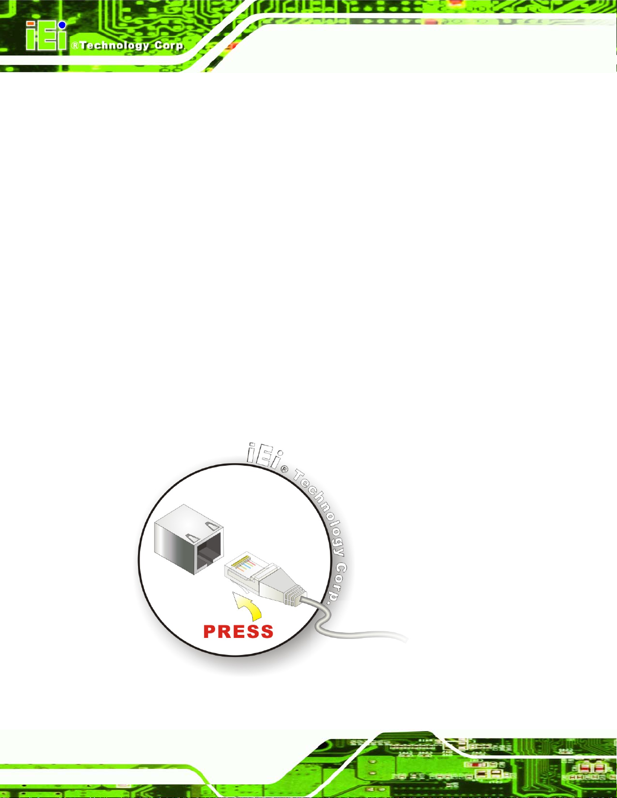
4.9.1 LAN Connection
There are two external RJ-45 LAN connectors. The RJ-45 connectors enable connection
to an external network. To connect a LAN cable with an RJ-45 connector, please follow
the instructions below.
Step 1: Locate the RJ-45 connectors on the bottom panel of the AFL-9652 Series.
Step 2: Align the connectors. Align the RJ-45 connector on the LAN cable with one of
the RJ-45 connectors on the bottom panel of the AFL-9652 series. See
4-21.
Figure 4-20).Step 0:
Figure
Page 46
Figure 4-21: LAN Connection
Page 65

Step 3: Insert the LAN cable RJ-45 connector. Once aligned, gently insert the LAN
cable RJ-45 connector into the onboard RJ-45 connector. Step 0:
4.9.2 Serial Device Connection
The AFL-9652 Series has two single female DB-9 connectors on the bottom panel for a
serial device. Follow the steps below to connect a serial device to the AFL-9652 Series
panel PC.
Step 1: Locate the DB-9 connector. The location of the DB-9 connector is shown in
Chapter 2.
Step 2: Insert the serial connector. Insert the DB-9 connector of a serial device into
the DB-9 connector on the bottom panel. See
Figure 4-22.
Figure 4-22: Serial Device Connector
Step 3: Secure the connector. Secure the serial device connector to the external
interface by tightening the two retention screws on either side of the connector.
Step 0:
Page 47
Page 66
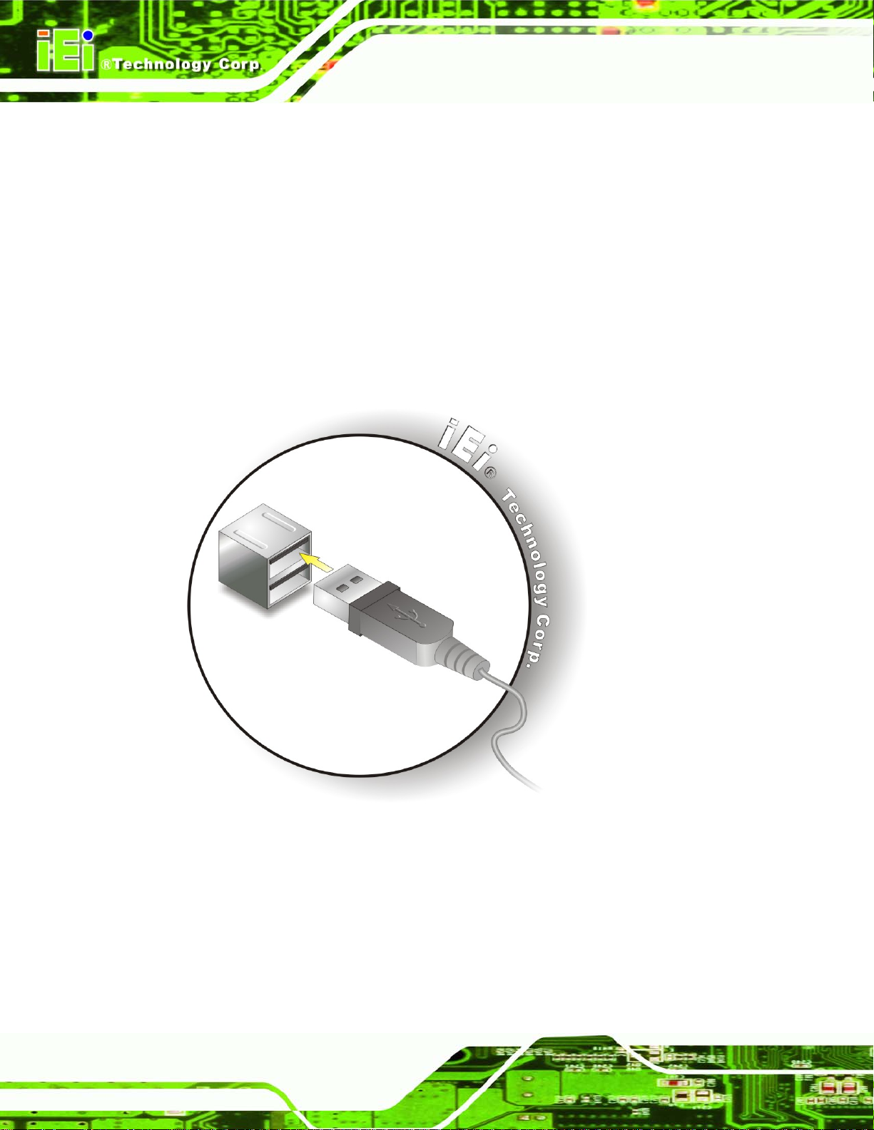
4.9.3 USB Device Connection
There are four external USB 2.0 connectors. All connectors are perpendicular to the
AFL-9652 series. To connect a USB 2.0 or USB 1.1 device, please follow the instructions
below.
Step 1: Locate the USB connectors. The locations of the USB connectors are shown
in Chapter 2.
Step 2: Align the connectors. Align the USB device connector with one of the
connectors on the bottom panel. See
Figure 4-23.
Page 48
Figure 4-23: USB Device Connection
Step 3: Insert the device connector. Once aligned, gently insert the USB device
connector into the onboard connector. Step 0:
Page 67
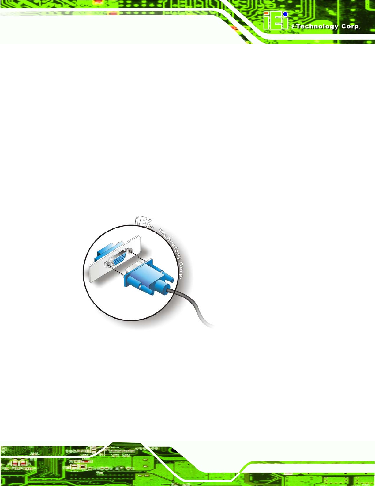
4.9.4 VGA Monitor Connection
The AFL-9652 has a single female DB-15 connector on the external peripheral interface
panel. The DB-15 connector is connected to a CRT or VGA monitor. To connect a monitor
to the AFL-9652, please follow the instructions below.
Step 1: Locate the female DB-15 connector. The location of the female DB-15
connector is shown in Chapter 3.
Step 2: Align the VGA connector. Align the male DB-15 connector on the VGA screen
cable with the female DB-15 connector on the external peripheral interface.
Step 3: Insert the VGA connector. Once the connectors are properly aligned with the
insert the male connector from the VGA screen into the female connector on the
AFL-9652. See
Figure 4-24.
Figure 4-24: VGA Connector
Step 4: Secure the connector. Secure the DB-15 VGA connector from the VGA
monitor to the external interface by tightening the two retention screws on either
side of the connector. Step 0:
Page 49
Page 68

Chapter
5
5 System Maintenance
Page 50
Page 69

5.1 Introduction
If the components of the AFL-9652 series fail they must be replaced, such as the wireless
LAN module or the motherboard. Please contact the system reseller or vendor to
purchase the replacement parts. Back cover removal instructions and jumper settings for
the AFL-9652 series are described below.
5.2 Motherboard Replacement
A user cannot replace a motherboard. If the motherboard fails it must be shipped back to
IEI to be replaced. If the system motherboard has failed, please contact the system vendor,
reseller or an IEI sales person directly.
5.3 Internal Aluminum Cover Removal
WARNING!
Turn the power off before removing the back cover. Failing to do so
may lead to severe damage of AFL-9652 series and injury to the body.
Over-tightening back cover screws will crack the plastic frame. Maximum
torque for cover screws is 5 kg-cm (0.36 lb-ft/0.49 Nm).
WARNING!
Take antistatic precautions when working with internal components.
The interior of the AFL-9652 series contains very sensitive electronic
components. These components are easily damaged by electrostatic
discharge (ESD). Before working with the internal components make sure
all the anti-static precautions described earlier have been observed.
Page 51
Page 70

To replace any of the following components,
DDR2 memory module
Wireless LAN module
Inverter
The internal aluminum back cover of the AFL-9652 series must be removed. To remove
the aluminum back cover, remove the retention screws indicated in the sections below.
Remove the following screws:
2 x Flat head screws
8 x Round head screws
Screw positions are indicated below (
Figure 5-1: Aluminum Back Cover Retention Screws
Figure 5-1).
5.4 Memory Module Replacement
Page 52
The flat panel PC is preinstalled with a DDR2 memory module. If the memory module fails,
follow the instructions below to replace the memory module.
Step 1: Remove the back cover. See Section
Step 2: Remove the internal aluminum back cover. See Section
4.5 above.
5.3 above.
Page 71

Step 3: Locate the DDR2 memory module on the motherboard of the flat panel PC
Figure 5-2).
(
Figure 5-2: SO-DIMM Socket Locations
Step 4: Remove the DDR2 memory module by pulling both the spring retainer clips
outward from the socket.
Step 5: Grasp the DDR2 memory module by the edges and carefully pull it out of the
socket.
Step 6: Install the new DDR2 memory module by pushing it into the socket at an angle
Figure 5-3).
(
Step 7: Gently pull the spring retainer clips of the SO-DIMM socket out and push the
rear of the DDR2 memory module down (
Step 8: Release the spring retainer clips on the SO-DIMM socket. They clip into place
and secure the DDR2 memory module in the socket.Step 0:
Figure 5-3).
Page 53
Page 72

Figure 5-3: DDR2 SO-DIMM Module Installation
5.5 Jumper Settings
NOTE:
A jumper is a metal bridge that is used to
close an electrical circuit. It consists of
two metal pins and a small metal clip
(often protected by a plastic cover) that
slides over the pins to connect them.
To CLOSE/SHORT a jumper means
connecting the pins of the jumper with
the plastic clip and to OPEN a jumper
means removing the plastic clip from a
jumper.
The six jumpers listed below are located on the motherboard and can be setup for
AFL-9652 series.
Jumper
Page 54
Clear CMOS jumper (J_CMOS1)
COM1 and COM3 RI and voltage select (J10)
COM3 RS-232/422/485 select (J9)
CompactFlash® setup (J4)
Page 73
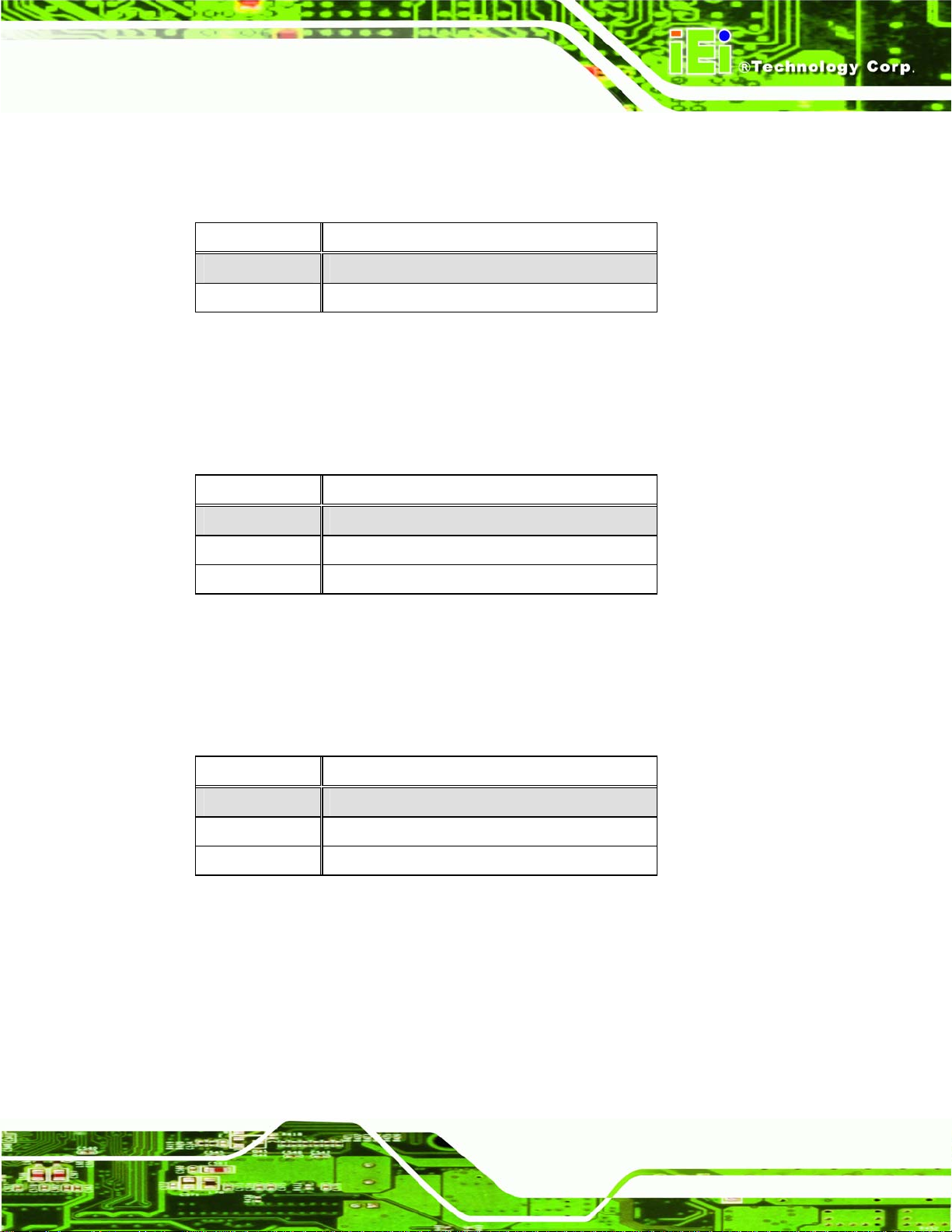
5.5.1 Clear CMOS Jumper (J_CMOS1)
The Clear CMOS jumper setting is used to reset the CMOS to default settings.
J_CMOS1 Description
1-2 Normal Operation
2-3 Clear CMOS Setup
Table 5-1: Clear CMOS Jumper Settings
5.5.2 COM1 RI and Voltage Select (J10)
The COM1 pin-9 signal can be selected as 12V, 5V or Ring.
J10 Description
7-9 Use for RI
3-5 5 V
1-3 12 V
Table 5-2: COM1 RI and Voltage Settings
5.5.3 COM3 RI and Voltage Select (J10)
The COM3 pin-9 signal can be selected as 12V, 5V or Ring.
J10 Description
8-10 Use for RI
4-6 5 V
2-4 12 V
Table 5-3: COM3 RI and Voltage Settings
Page 55
Page 74
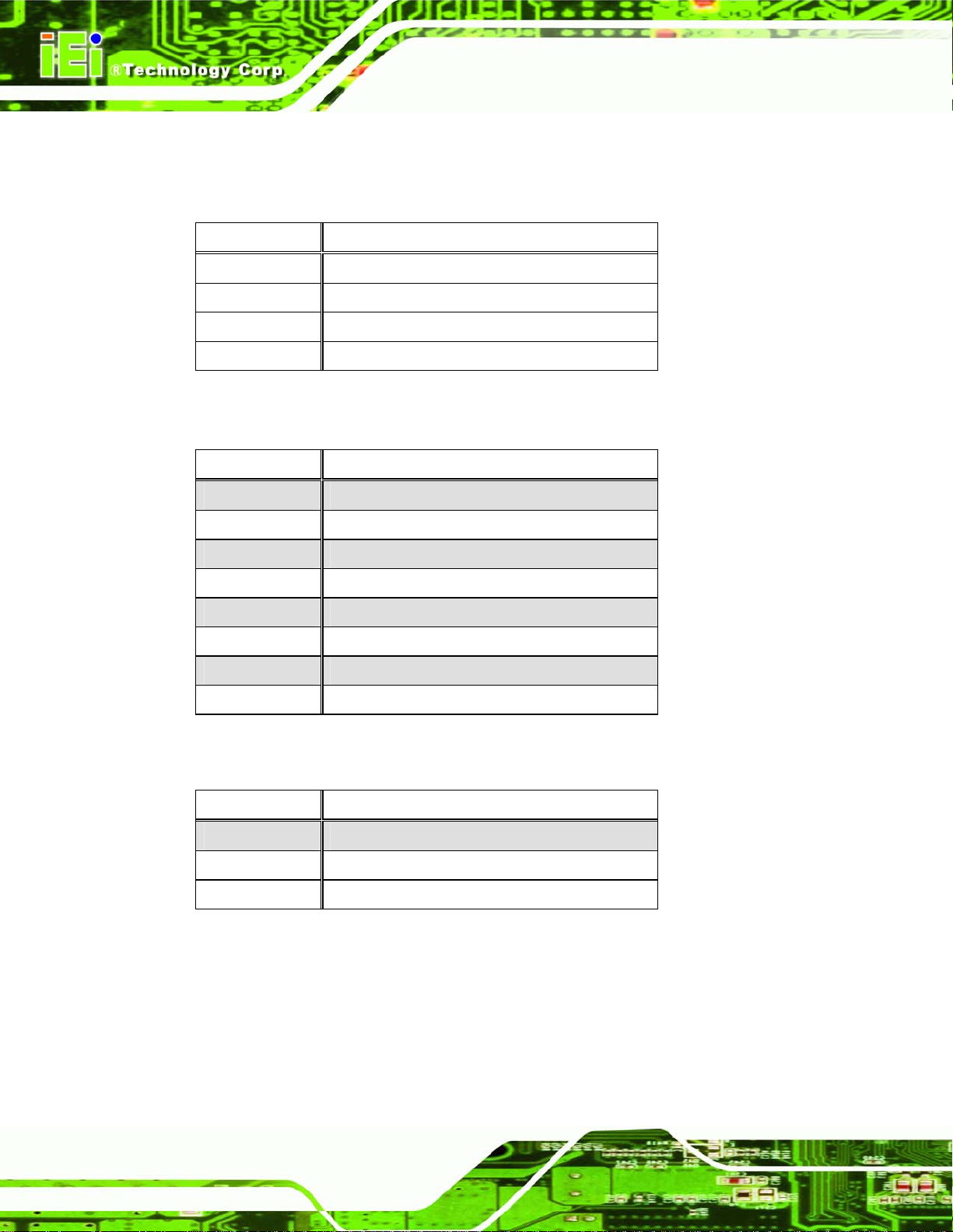
5.5.4 COM3 Mode Select
The following jumper selects RS-232, RS-422 or RS-485 mode for the COM3 serial port.
J7 Description
1-3 RS-422 TX-
3-5 RS-485 D2-4 RS-422 TX+
4-6 RS-485 D+
Table 5-4: COM3 RS-422/485 Selection
J8 Description
Short 1-2 DCD3 (RS-232)
Short 2-3 TX3- (RS-422/485)
Short 4-5 RXD3 (RS-232)
Short 5-6 TX3+ (RS-422/485)
Short 7-8 DSR3 (RS-232)
Short 8-9 RX3- (RS-422/485)
Short 10-11 RTS3 (RS-232)
Short 11-12 RX3+ (RS-422/485)
Table 5-5: COM3 Mode Selection
J9 Description
1-2 RS-232
3-4 RS-422
5-6 RS-485
Table 5-6: COM3 Mode Selection
Page 56
Page 75
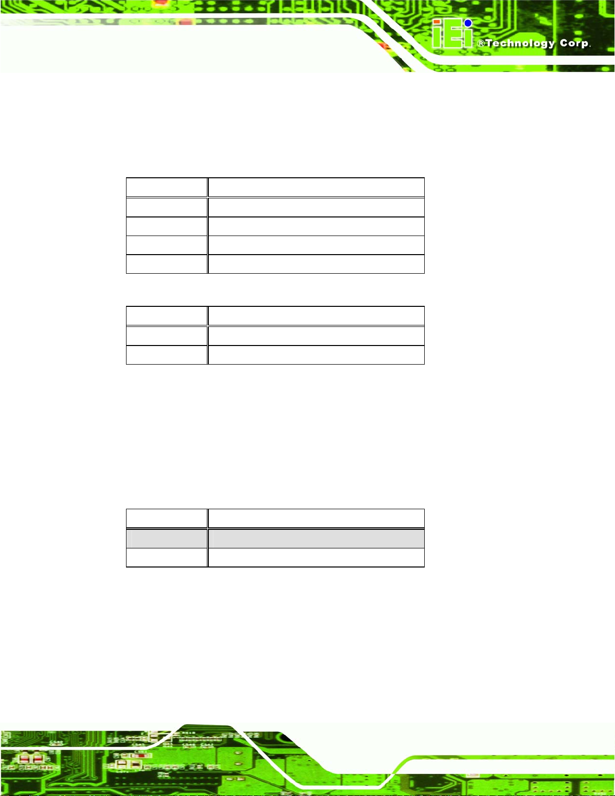
5.5.4.1 COM3 RS-422 and RS-485 Pinouts
The pinouts for RS-422 and RS-485 operation of external serial port COM 3 are detailed
below.
COM 3 RS-422 Description
Pin 1 TXPin 2 TX+
Pin 6 RXPin 7 RX+
Table 5-7: RS-422 Pinouts
COM 3 RS-485 Description
Pin 1 Data-
Pin 2 Data+
Table 5-8: RS-485 Pinouts
5.5.5 CompactFlash® Setup (J4)
The Master/Slave selection allows the CompactFlash® slot to be setup as either the IDE
master or the IDE slave. If no other IDE device is used in the system, then the setting does
not need to be changed.
J4 Description
Short Master
Open Slave
Table 5-9: CompactFlash® Master/Slave Selection
Page 57
Page 76

Chapter
6
6 AMI BIOS Setup
Page 58
Page 77
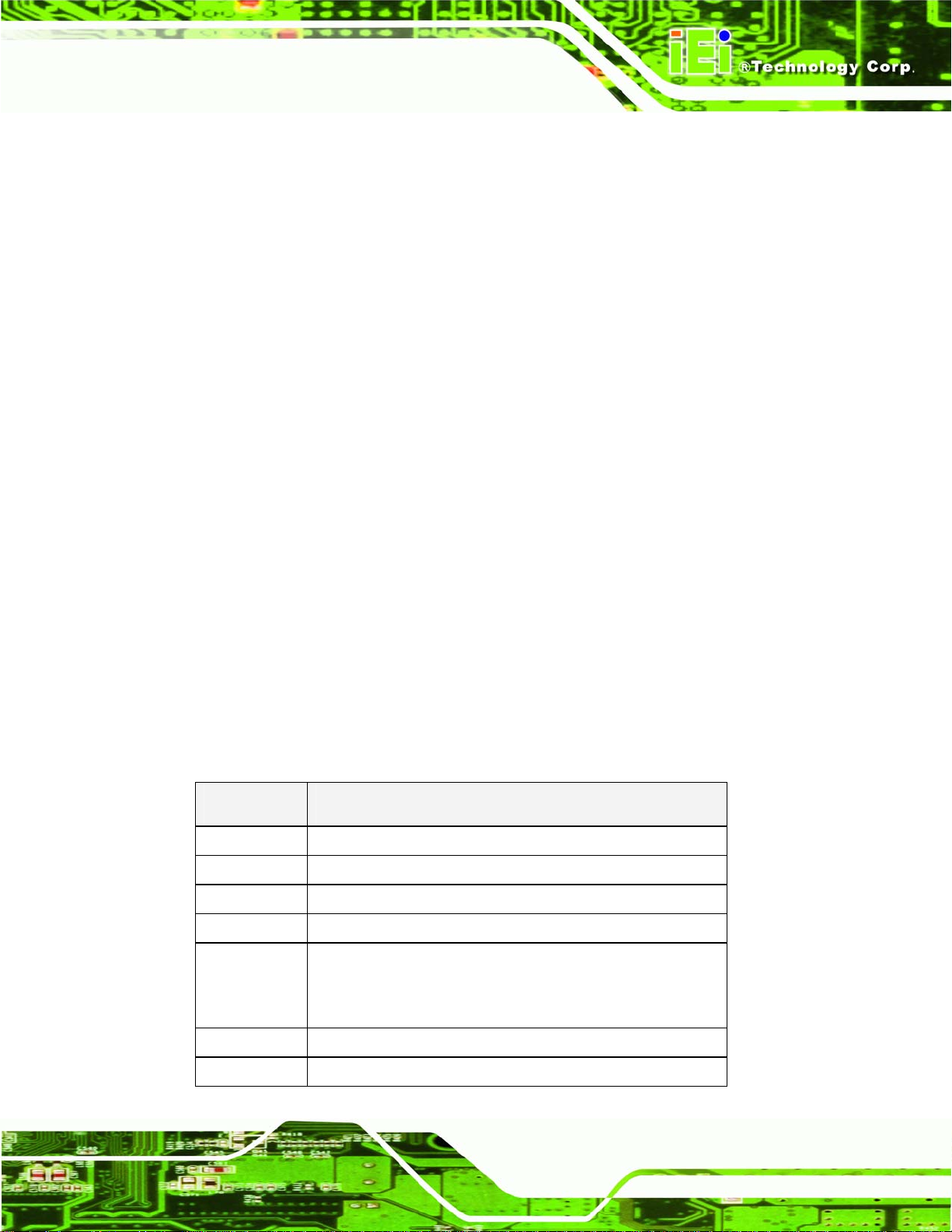
6.1 Introduction
A licensed copy of AMI BIOS is preprogrammed into the ROM BIOS. The BIOS setup
program allows users to modify the basic system configuration. This chapter describes
how to access the BIOS setup program and the configuration options that may be
changed.
6.1.1 Starting Setup
The AMI BIOS is activated when the computer is turned on. The setup program can be
activated in one of two ways.
1. Press the D
2. Press the D
message appears on the screen. 0.
If the message disappears before the D
again.
ELETE key as soon as the system is turned on or
ELETE key when the “Press Del to enter SETUP”
ELETE key is pressed, restart the computer and try
6.1.2 Using Setup
Use the arrow keys to highlight items, press ENTER to select, use the PageUp and
PageDown keys to change entries, press F1 for help and press E
keys are shown in.
Key Function
Up arrow Move to previous item
Down arrow Move to next item
Left arrow Move to the item on the left hand side
SC to quit. Navigation
Right arrow Move to the item on the right hand side
Esc key Main Menu – Quit and not save changes into CMOS
Status Page Setup Menu and Option Page Setup Menu --
Exit current page and return to Main Menu
Page Up key Increase the numeric value or make changes
Page Dn key Decrease the numeric value or make changes
Page 59
Page 78

F1 key General help, only for Status Page Setup Menu and Option
F2 /F3 key Change color from total 16 colors. F2 to select color
F10 key Save all the CMOS changes, only for Main Menu
Table 6-1: BIOS Navigation Keys
6.1.3 Getting Help
When F1 is pressed a small help window describing the appropriate keys to use and the
Page Setup Menu
forward.
possible selections for the highlighted item appears. To exit the Help Window press E
the F1 key again.
6.1.4 Unable to Reboot After Configuration Changes
If the computer cannot boot after changes to the system configuration is made, CMOS
defaults. Use the jumper described in Chapter 5 or disconnect the battery from the
connector.
6.1.5 BIOS Menu Bar
The menu bar on top of the BIOS screen has the following main items:
Main Changes the basic system configuration.
Advanced Changes the advanced system settings.
PCIPnP Changes the advanced PCI/PnP Settings
Boot Changes the system boot configuration.
Security Sets User and Supervisor Passwords.
SC or
Page 60
Chipset Changes the chipset settings.
Exit Selects exit options and loads default settings
The following sections completely describe the configuration options found in the menu
items at the top of the BIOS screen and listed above.
Page 79
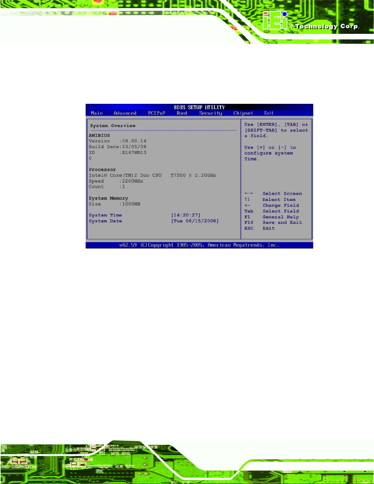
6.2 Main
The Main BIOS menu (BIOS Menu 1) appears when the BIOS Setup program is entered.
The Main menu gives an overview of the basic system information.
BIOS Menu 1: Main
System Overview
The System Overvie w lists a brief summary of different system components. The fields in
System Overview cannot be changed. The items shown in the system overview include:
AMI BIOS: Displays auto-detected BIOS information
o Version: Current BIOS version
o Build Date: Date the current BIOS version was made
o ID: Installed BIOS ID
Processor: Displays auto-detected CPU specifications
o Type: Names the currently installed processor
o Speed: Lists the processor speed
o Count: The number of CPUs on the motherboard
System Memory: Displays the auto-detected system memory.
Page 61
Page 80

o Size: Lists memory size
The System Overview field also has two user configurable fields:
System Time [xx:xx:xx]
Use the System Time option to set the system time. Manually enter the hours, minutes
and seconds.
System Date [xx/xx/xx]
Use the System Date option to set the system date. Manually enter the day, month and
year.
6.3 Advanced
Use the Advanced menu (BIOS Menu 2) to configure the CPU and peripheral devices
through the following sub-menus:
WARNING!
Setting the wrong values in the sections below may cause the system to
malfunction. Make sure that the settings made are compatible with the
hardware.
CPU Configuration (see Section 6.3.1)
IDE Configuration (see Section 6.3.2)
Super IO Configuration (see Section 6.3.3)
Hardware Health Configuration (see Section 6.3.4)
Intel AMT Configuration (see Section 6.3.5)
Intel Robson Configuration (see Section 6.3.6)
Remote Access Configuration (see Section 6.3.7)
Page 62
USB Configuration (see Section 6.3.8)
Power Configuration (see Section 6.3.9)
Page 81
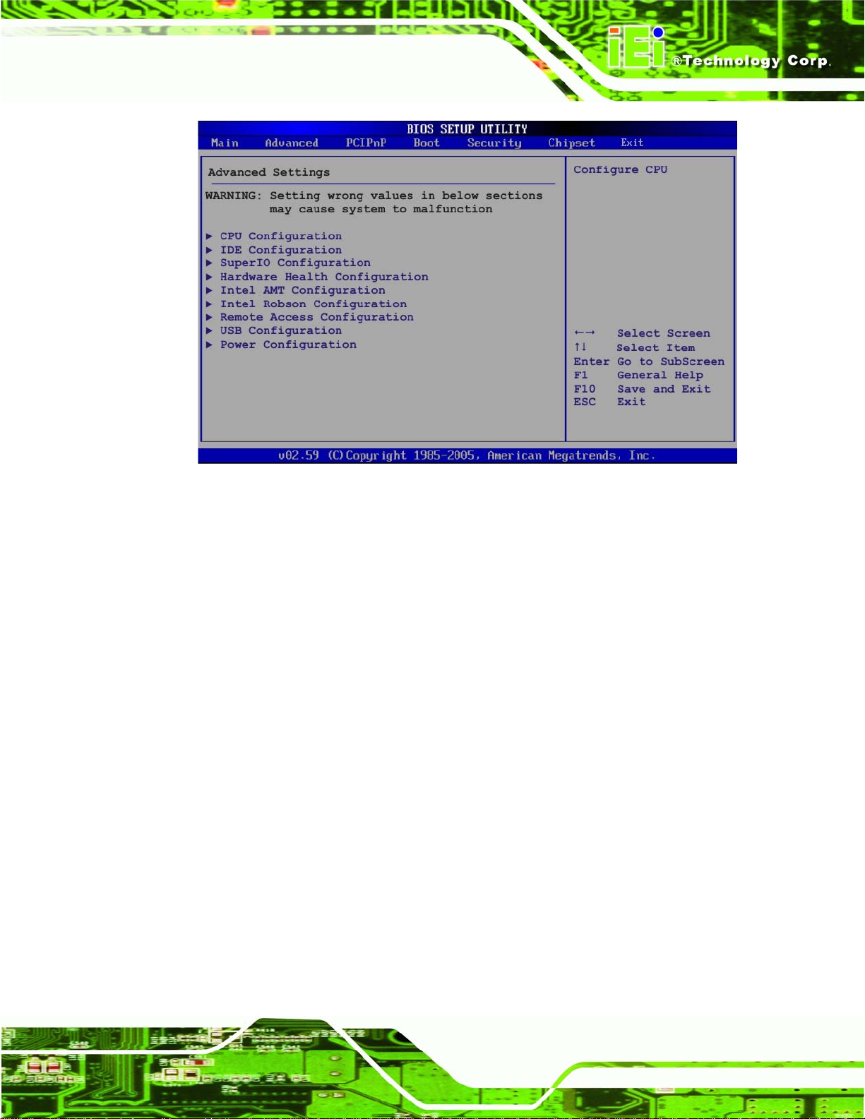
BIOS Menu 2: Advanced
6.3.1 CPU Configuration
Use the CPU Configuration menu (BIOS Menu 3) to view detailed CPU specifications
and configure the CPU.
Page 63
Page 82

BIOS Menu 3: CPU Configuration
The CPU Configuration menu (
Manufacturer: Lists the name of the CPU manufacturer
Brand String: Lists the brand name of the CPU being used
Frequency: Lists the CPU processing speed
FSB Speed: Lists the FSB speed
Cache L1: Lists the CPU L1 cache size
Cache L2: Lists the CPU L2 cache size
BIOS Menu 3) lists the following CPU details:
Intel (R) SpeedStep (tm) tech. [Enabled]
Use the Intel (R) SpeedStep (tm) tech. option to enable or disable GV3. GV3 technology
is a power-saving scheme where the OS optimizes overall power consumption by
dynamically changing CPU frequency based on demand.
Page 64
Disabled
Enabled D
Disables SpeedStep i.e. GV3
EFAULT
Enables SpeedStep i.e. GV3
Page 83

6.3.2 IDE Configuration
Use the IDE Configuration menu (BIOS Menu 4) to change and/or set the configuration
of the IDE devices installed in the system.
BIOS Menu 4: IDE Configuration
ATA/IDE Configurations [Compatible]
Use the ATA/IDE Configurations option to configure the ATA/IDE controller.
Disabled
Compatible DEFAULT
Enhanced
Disables the on-board ATA/IDE controller.
Configures the on-board ATA/IDE controller to be in
compatible mode. In this mode, a SATA channel will
replace one of the IDE channels. This mode supports up
to 4 storage devices.
Configures the on-board ATA/IDE controller to be in
Enhanced mode. In this mode, IDE channels and SATA
channels are separated. This mode supports up to 6
Page 65
Page 84

Legacy IDE Channels [SATA Only]
storage devices. Some legacy OS do not support this
mode.
SA TA Only DEFAULT
SA TA Pri., PATA Sec
PATA Only
IDE Master and IDE Slave
When entering setup, BIOS auto detects the presence of IDE devices. BIOS displays the
status of the auto detected IDE devices. The following IDE devices are detected and are
shown in the IDE Configuration menu:
Primary IDE Master
Primary IDE Slave
Secondary IDE Master
Secondary IDE Slave
Third IDE Master
Third IDE Slave
Page 66
Fourth IDE Master
Fourth IDE Slave
The IDE Configuration menu (
IDE devices installed in the system. If an IDE device is detected, and one of the above
listed four BIOS configuration options are selected, the IDE configuration options shown in
Section
6.3.2.1 appear.
BIOS Menu 4) allows changes to the configurations for the
6.3.2.1 IDE Master, IDE Slave
Use the IDE Master and IDE Slave configuration menu to view both primary and
secondary IDE device details and configure the IDE devices connected to the system.
Page 85

BIOS Menu 5: IDE Master and IDE Slave Configuration
Type [Auto]
Use the Type BIOS option select the type of device the AMIBIOS attempts to boot from
after the Power-On Self-Test (POST) is complete.
Not Installed
Auto DEFAULT
CD/DVD
BIOS is prevented from searching for an IDE disk
drive on the specified channel.
The BIOS auto detects the IDE disk drive type
attached to the specified channel. This setting should
be used if an IDE hard disk drive is attached to the
specified channel.
The CD/DVD option specifies that an IDE CD-ROM
drive is attached to the specified IDE channel. The
BIOS does not attempt to search for other types of
Page 67
Page 86

IDE disk drives on the specified channel.
ARMD
LBA/Large Mode [Auto]
Use the LBA/Large Mode option to disable or enable BIOS to auto detects LBA (Logical
Block Addressing). LBA is a method of addressing data on a disk drive. In LBA mode, the
maximum drive capacity is 137 GB.
Disabled
Auto DEFAULT
This option specifies an ATAPI Removable Media
Device. These include, but are not limited to:
ZIP
LS-120
BIOS is prevented from using the LBA mode control on
the specified channel.
BIOS auto detects the LBA mode control on the specified
channel.
Block (Multi Sector Transfer) [Auto]
Use the Block (Multi Sector Transfer) to disable or enable BIOS to auto detect if the
device supports multi-sector transfers.
Disabled
Auto DEFAULT
BIOS is prevented from using Multi-Sector Transfer on the
specified channel. The data to and from the device occurs
one sector at a time.
BIOS auto detects Multi-Sector Transfer support on the
drive on the specified channel. If supported the data
transfer to and from the device occurs multiple sectors at
a time.
Page 68
Page 87

PIO Mode [Auto]
Use the PIO Mode option to select the IDE PIO (Programmable I/O) mode program timing
cycles between the IDE drive and the programmable IDE controller. As the PIO mode
increases, the cycle time decreases.
Auto DEFAULT
0
1
2
3
4
DMA Mode [Auto]
PIO mode 0 selected with a maximum transfer rate of 3.3MBps
PIO mode 1 selected with a maximum transfer rate of 5.2MBps
PIO mode 2 selected with a maximum transfer rate of 8.3MBps
PIO mode 3 selected with a maximum transfer rate of 11.1MBps
PIO mode 4 selected with a maximum transfer rate of 16.6MBps
BIOS auto detects the PIO mode. Use this value if the IDE disk
drive support cannot be determined.
(This setting generally works with all hard disk drives
manufactured after 1999. For other disk drives, such as IDE
CD-ROM drives, check the specifications of the drive.)
Use the DMA Mode BIOS selection to adjust the DMA mode options.
Auto DEFAULT
SWDMA0
SWDMA1
SWDMA2
Single Word DMA mode 0 selected with a maximum data
Single Word DMA mode 1 selected with a maximum data
Single Word DMA mode 2 selected with a maximum data
BIOS auto detects the DMA mode. Use this value if the IDE
disk drive support cannot be determined.
transfer rate of 2.1MBps
transfer rate of 4.2MBps
transfer rate of 8.3MBps
Page 69
Page 88

MWDMA0
MWDMA1
MWDMA2
UDMA1
UDMA1
UDMA2
Multi Word DMA mode 0 selected with a maximum data
transfer rate of 4.2MBps
Multi Word DMA mode 1 selected with a maximum data
transfer rate of 13.3MBps
Multi Word DMA mode 2 selected with a maximum data
transfer rate of 16.6MBps
Ultra DMA mode 0 selected with a maximum data transfer
rate of 16.6MBps
Ultra DMA mode 1 selected with a maximum data transfer
rate of 25MBps
Ultra DMA mode 2 selected with a maximum data transfer
rate of 33.3MBps
UDMA3
UDMA4
UDMA5
S.M.A.R.T [Auto]
Use the S.M.A.R.T option to auto-detect, disable or enable Self-Monitoring Analysis and
Reporting Technology (SMART) on the drive on the specified channel. S.M.A.R.T predicts
Ultra DMA mode 3 selected with a maximum data transfer
rate of 44MBps (To use this mode, it is required that an
80-conductor ATA cable is used.)
Ultra DMA mode 4 selected with a maximum data transfer
rate of 66.6MBps (To use this mode, it is required that an
80-conductor ATA cable is used.)
Ultra DMA mode 5 selected with a maximum data transfer
rate of 99.9MBps (To use this mode, it is required that an
80-conductor ATA cable is used.)
Page 70
impending drive failures. The S.M.A.R.T BIOS option enables or disables this function.
Page 89

Auto DEFAULT
Disabled
Enabled
32Bit Data Transfer [Enabled]
Use the 32Bit Data Transfer BIOS option to enables or disable 32-bit data transfers.
Disabled
Enabled DEFAULT
Prevents BIOS from using the HDD SMART feature.
Allows BIOS to use the HDD SMART feature
Prevents the BIOS from using 32-bit data transfers.
BIOS auto detects HDD SMART support.
Allows BIOS to use 32-bit data transfers on supported
hard disk drives.
6.3.3 Super IO Configuration
Use the Super IO Configuration menu (BIOS Menu 6) to set or change the
configurations for the FDD controllers, parallel ports and serial ports.
BIOS Menu 6: Super IO Configuration
Page 71
Page 90

Serial Port1 Address [3F8/IRQ4]
Use the Serial Port1 Address option to select the Serial Port 1 base address.
Disabled
3F8/IRQ4 DEFAULT
3E8/IRQ4
2E8/IRQ3
Serial Port2 Address [2F8/IRQ3]
Use the Serial Port2 Address option to select the Serial Port 2 base address.
Disabled
2F8/IRQ3 DEFAULT
No base address is assigned to Serial Port 1
Serial Port 1 I/O port address is 3F8 and the interrupt
address is IRQ4
Serial Port 1 I/O port address is 3E8 and the interrupt
address is IRQ4
Serial Port 1 I/O port address is 2E8 and the interrupt
address is IRQ3
No base address is assigned to Serial Port 2
Serial Port 2 I/O port address is 3F8 and the interrupt
3E8/IRQ4
2E8/IRQ3
Serial Port3 Address [3E8]
Use the Serial Port3 Address option to select the base addresses for serial port 3
Page 72
Disabled
3F8
No base address is assigned to serial port 3
address is IRQ3
Serial Port 2 I/O port address is 3E8 and the interrupt
address is IRQ4
Serial Port 2 I/O port address is 2E8 and the interrupt
address is IRQ3
Serial port 3 I/O port address is 3F8
Page 91

2F8
3E8 DEFAULT
2E8
Serial Port3 IRQ [10]
Use the Serial Port3 IRQ option to select the interrupt address for serial port 3.
10 DEFAULT
Serial Port4 Address [2E8]
Use the Serial Port4 IRQ option to select the interrupt address for serial port 4.
Disabled
3F8
Serial port 3 I/O port address is 2F8
Serial port 3 I/O port address is 3E8
Serial port 3 I/O port address is 2E8
Serial port 3 IRQ address is 10
No base address is assigned to serial port 3
Serial port 4 I/O port address is 3F8
2F8
3E8
2E8 DEFAULT
Serial Port4 IRQ [10]
Use the Serial Port4 IRQ option to select the interrupt address for serial port 4.
10 DEFAULT
Serial port 4 I/O port address is 2F8
Serial port 4 I/O port address is 3E8
Serial port 4 I/O port address is 2E8
Serial port 4 IRQ address is 10
6.3.4 Hardware Health Configuration
The Hardware Health Configuration menu (BIOS Menu 7) shows the operating
temperature, fan speeds and system voltages.
Page 73
Page 92

BIOS Menu 7: Hardware Health Configuration
FAN Mode Setting [Full On Mode]
Use the FAN Mode Setting option to configure the CPU fan or system fans.
Full On Mode D
Automatic mode
PWM Manual mode
When the CPU FAN 1 Mode Setting option is in the Automatic Mode, the following
parameters can be set.
CPU Temp. Limit of OFF
EFAULT
Fan is on all the time
Fan is off when the temperature is low
enough. Parameters must be set by the
user.
Pulse width modulation set manually
Page 74
CPU Temp. Limit of Start
CPU Fan Start PWM
Slope PWM 1
Page 93
When the CPU FAN Mode Setting option is in the PWM Manual Mode, the following
parameters can be set.
CPU Fan PWM control
CPU Temp. Limit of OFF [000]
WARNING:
Setting this value too high may cause the fan to stop when the CPU is
at a high temperature and therefore cause the system to be damaged.
The CPU Temp. Limit of OFF option can only be set if the CPU FAN Mode Setting
option is set to Automatic Mode. Use the CPU Temp. Limit of OFF option to select the
CPU temperature at which the cooling fan should automatically turn off. To select a value,
select the CPU Temp. Limit of OFF option and enter a decimal number between 000 and
127. The temperature range is specified below.
Minimum Value: 0°C
Maximum Value: 127°C
CPU Temp. Limit of Start [020]
WARNING:
Setting this value too high may cause the fan to start only when the
CPU is at a high temperature and therefore cause the system to be
damaged.
The CPU Temp. Limit of Start option can only be set if the CPU FAN Mode Setting
option is set to Automatic Mode. Use the CPU Temp. Limit of Start option to select the
CPU temperature at which the cooling fan should automatically turn on. When the fan
Page 75
Page 94

starts, it rotates using the starting pulse width modulation (PWM) specified in the Fan 3
Start PWM option below. To select a value, select the CPU Temp. Limit of Start option
and enter a decimal number between 000 and 127. The temperature range is specified
below.
Minimum Value: 0°C
Maximum Value: 127°C
CPU Fan Start PWM [070]
The Fan 3 Start PWM option can only be set if the CPU FAN Mode Setting option is set
to Automatic Mode. Use the Fan 3 Start PWM option to select the PWM mode the fan
starts to rotate with after the temperature specified in the Temperature 3 Limit of Start is
exceeded. The Super I/O chipset supports 128 PWM modes. To select a value, select the
Fan 3 Start PWM option and enter a decimal number between 000 and 127. The
temperature range is specified below.
PWM Minimum Mode: 0
PWM Maximum Mode: 127
Slope PWM 1 [1 PWM]
The Slope PWM 1 option can only be set if the CPU FAN Mode Setting option is set to
Automatic Mode. Use the Slope PWM 1 option to select the linear rate at which the PWM
mode increases with respect to an increase in temperature. A list of available options is
shown below:
0 PWM
1 PWM
2 PWM
4 PWM
8 PWM
16 PWM
Page 76
32 PWM
64 PWM
Page 95

CPU Fan PWM Control [070]
The CPU Fan PWM Control option can only be set if the CPU FAN Mode Setting option
is set to Manual Mode. Use the CPU Fan PWM Control option to select PWM duty cycle
control. The PWM duty cycle specifies the width of the modulated pulse. A high value
ensures a wide pulse and a low value ensures a narrow pulse. To select a value, select
the CPU Fan PWM Control option and enter a decimal number between 000 and 127.
The PWM Duty Cycle control range is specified below.
PWM Minimum Mode: 0
PWM Maximum Mode: 127
The following system parameters and values are shown. The system parameters that are
monitored are:
System Temperatures: The following system temperatures are monitored
o CPU Temperature
o PWM Temperature
o System Temperature
Fan Speeds: The CPU cooling fan speed is monitored.
o CPU Fan1 Speed
o SYS_Fan1 Speed
o SYS_FAN2 Speed
Voltages: The following system voltages are monitored
o CPU Core
o +1.8V
o +3.30V
o +5.00V
o +12.0V
o +1.05V
o +1.5V
o +1.25V
o VBAT
Page 77
Page 96

6.3.5 Intel AMT Configuration
The Intel AMT Configuration menu (BIOS Menu 8) configures the Intel® Active
Management Technology (AMT) options.
BIOS Menu 8: Intel AMT Configuration
Intel AMT Support [Disabled]
Use the Intel AMT Support option to enable or disable the Intel AMT support.
Disabled DEFAULT
Enabled
The Intel® AMT function is disabled.
The Intel® AMT function is enabled.
6.3.5.1 ME Subsystem Configuration
The ME Subsystem Configuration menu (BIOS Menu 23) allows the AMT subsystem
(Management Engine, ME) and Host Embedded Controller Interface (HECI) driver options
to be configured.
Page 78
Page 97

BIOS Menu 9: Me Subsystem Configuration
BootBlock HECI Message [Enabled]
Use the BootBlock HECI Message option to enable or disable HECI message when
booting up the system.
Disabled
Enabled DEFAULT
HECI Message [Enabled]
Use the HECI Message BIOS option to enable or disable HECI message.
The HECI message is disabled when booting up the
system.
The HECI message is enabled when booting up the
system.
Disabled
The HECI message disabled.
Page 79
Page 98

Enabled DEFAULT
End Of Post S5 HECI Message [Enabled]
Use the End Of Post S5 HECI Message option to enable or disable HECI message when
the system is in the off (S5) state.
Disabled
Enabled DEFAULT
ME-HECI [Enabled]
The ME-HECI option is enabled by default and can not be changed.
ME-IDER [Disabled]
Use the ME-IDER option to enable or disable the IDE-Redirection (IDE-R) function on an
The HECI message is disabled when the system is off.
The HECI message enabled.
The HECI message enabled when the system is off.
AMT-capable system.
Disabled DEFAULT
Enabled
ME-KT [Disabled]
Use the ME-KT option to enable or disable the Keyboard and Text redirection (KT)
function on an AMT-capable system. KT is also known as Serial-Over-Lan (SOL).
Disabled DEFAULT
Enabled
The IDE-R function is disabled.
The IDE-R function allows an AMT-capable client system
to access IDE devices and load OS from a management
system. When an IDE-R session is established, the
virtual drives are shown in the system.
The KT function of the ME is disabled.
The KT function allows a management system to control
Page 80
an Intel® AMT client system remotely. The keyboard
Page 99

6.3.6 Intel Robson Configuration
The Intel Robson Configuration menu (BIOS Menu 10) allows the Intel® Robson
Technology option to be configured.
interface of a managed client system, such as BIOS
menu, is displayed through the management system.
BIOS Menu 10: Intel Robson Configuration
Intel Robson [Disabled]
Use the Intel Robson BIOS option to enable or disable the Intel® Robson Technology
feature. Intel® Robson, Intel® Turbo Memory, is a technology introduced by Intel® to
boost a computer startup process.
Disabled DEFAULT
Enabled
Disables the Intel® Robson feature
Enables the Intel® Robson feature
Page 81
Page 100
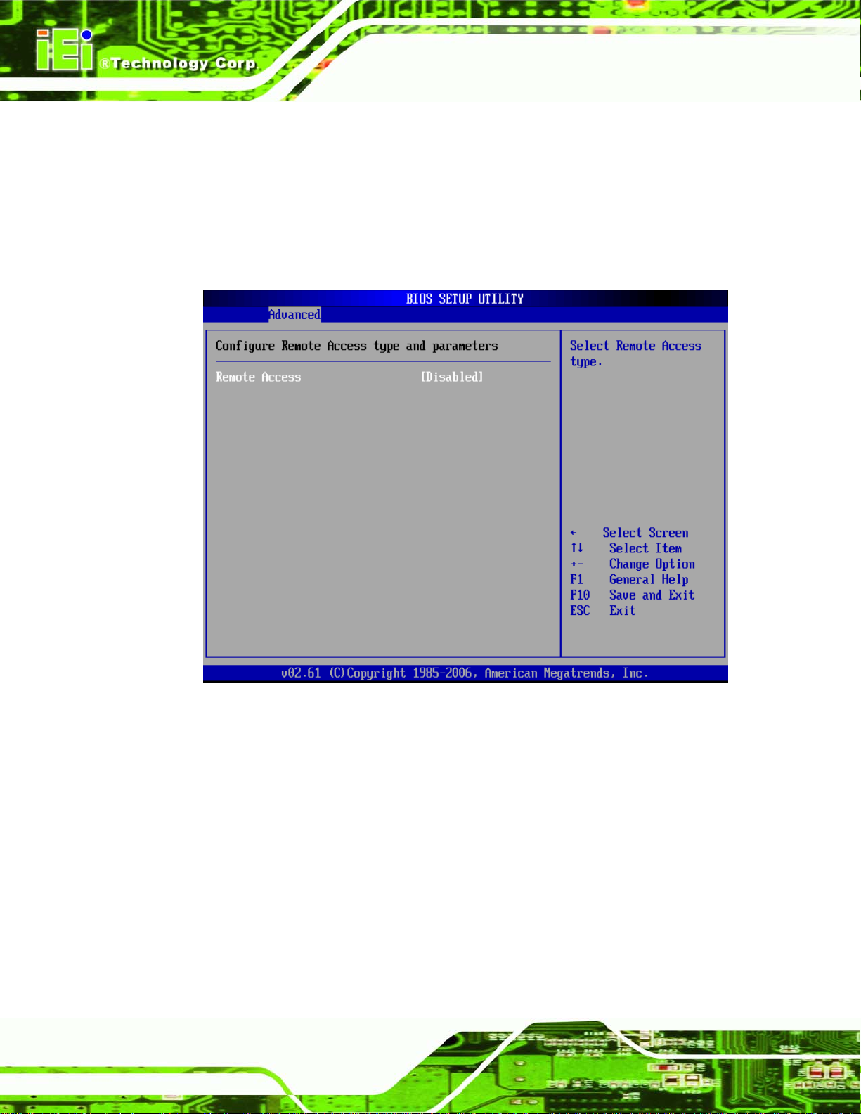
6.3.7 Remote Access Configuration
Use the Remote Access Configuration menu (BIOS Menu 11) to configure remote
access parameters. The Remote Access Configuration is an AMIBIOS feature and
allows a remote host running a terminal program to display and configure the BIOS
settings.
BIOS Menu 11: Remote Access Configuration [Advanced]
Remote Access [Disabled]
Use the Remote Access option to enable or disable access to the remote functionalities
of the system.
Disabled DEFAULT
Enabled
Page 82
Remote access is disabled.
Remote access configuration options shown below
appear:
 Loading...