

Page 1

IEI Technology Corp.
User Manual
AFL M Series LCD Monitor
MODEL:
AFOLUX M Series
7"~19" Multimedia Touch Monitor with Built-in Speakers,
VGA, Component, Composite, S-Video and DVI-D Input
IP 64 Protection
Rev. 1.12 – 10 March, 2011
Page i
Page 2

AFL M Series LCD Monitor
Revision
Date Version Changes
10 March, 2011 1.12 Updated Section 37.2 37-inch to 12.1-inch Driver
Installation and Configuration
29 September, 2009 1.11 Added screw torque warning
05 December, 2007 1.10 Added AFL-10M model information
Added USB touch screen feature to 7” to 12.1” models
Added USB touch screen models for 15” to 19” models
Added smartOSD function and smartOSD appendix
Added 7” to 12.1” model driver installation procedures
Added screen calibration procedures
30 June, 2007 1.00 Initial release
Page ii
Page 3

AFL M Series LCD Monitor
COPYRIGHT NOTICE
The information in this document is subject to change without prior notice in order to
improve reliability, design and function and does not represent a commitment on the part
of the manufacturer.
In no event will the manufacturer be liable for direct, indirect, special, incidental, or
consequential damages arising out of the use or inability to use the product or
documentation, even if advised of the possibility of such damages.
This document contains proprietary information protected by copyright. All rights are
Copyright
reserved. No part of this manual may be reproduced by any mechanical, electronic, or
other means in any form without prior written permission of the manufacturer.
TRADEMARKS
IBM PC is a registered trademark of International Business Machines Corporation. INTEL
is a registered trademark of INTEL Corporation. Other product names mentioned herein
are used for identification purposes only and may be trademarks and/or registered
trademarks of their respective owners.
Page iii
Page 4

AFL M Series LCD Monitor
Manual Conventions
WARNING!
Warnings appear where overlooked details may cause damage to the equipment or result
in personal injury. Warnings should be taken seriously. Warnings are easy to recognize.
The word “warning” is written as “WARNING,” both capitalized and bold and is followed by
text. The text is the warning message. A warning message is shown below:
WARNING:
This is an example of a warning message. Failure to adhere to warning
messages may result in permanent damage to the AFL series monitor
or personal injury to the user. Please take warning messages seriously.
CAUTION!
Cautionary messages should also be heeded to help reduce the chance of losing data or
damaging the AFL series monitor. Cautions are easy to recognize. The word “caution” is
written as “CAUTION,” both capitalized and bold and is followed. The italicized text is the
cautionary message. A caution message is shown below:
Page iv
Page 5

AFL M Series LCD Monitor
CAUTION:
This is an example of a caution message. Failure to adhere to cautions
messages may result in permanent damage to the AFL series monitor.
Please take caution messages seriously.
NOTE:
These messages inform the reader of essential but non-critical information. These
messages should be read carefully as any directions or instructions contained therein can
help avoid making mistakes. Notes are easy to recognize. The word “note” is written as
“NOTE,” both capitalized and bold and is followed by text. The text is the cautionary
message. A note message is shown below:
NOTE:
This is an example of a note message. Notes should always be read.
Notes contain critical information about the AFL series monitor. Please
take note messages seriously.
Page v
Page 6

AFL M Series LCD Monitor
Packing List
NOTE:
If any of the components listed in the checklist below are missing,
please do not proceed with the installation. Contact the IEI reseller or
vendor you purchased the AFL M series from or contact an IEI sales
representative directly. To contact an IEI sales representative, please
send an email to
The items listed below should all be included in the AFL M series package.
0sales@iei.com.tw.
z 1 x AFL M Series industrial LCD monitor
z 1 x Power adapter
z 1 x Power cord
z 1 x DVI cable
z 1 x VGA cable
z 1 x Component cable
z 1 x Audio cable
z 1 x User manual and driver CD
z 1 x Remote control
z 1 x Screw set
z 1 x Wire strain bands
z 1 x Touch Panel RS-232 Cable / Touch Pen / Driver CD-ROM (T-R
models only)
z 1 x Touch Panel USB Cable (for AFL-07M/T-R, AFL-08MH/T-R,
AFL-10M/T-R, and AFL-12M/T-R)
Images of the above items are shown in Chapter 383H383H5.3.3.
Page vi
Page 7

AFL M Series LCD Monitor
Table of Contents
1H1H1 INTRODUCTION.......................................................................................................... 384H384H1
2H2H1.1 AFL M SERIES LCD MONITOR OVERVIEW ................................................................ 385H385H3
3H3H1.1.1 Added Features .................................................................................................. 386H386H3
4H4H1.1.2 Standard Features.............................................................................................. 387H387H3
5H5H1.1.3 IEI smartOSD..................................................................................................... 388H388H4
6H6H1.1.4 Model Variations................................................................................................ 389H389H4
7H7H1.2 EXTERNAL OVERVIEW................................................................................................ 390H390H5
8H8H1.2.1 Front View.......................................................................................................... 391H391H5
9H9H1.2.2 Rear View........................................................................................................... 392H392H6
10H10H1.3 SERIES SPECIFICATIONS.............................................................................................. 393H393H7
11H11H1.4 CERTIFICATIONS......................................................................................................... 394H394H8
12H12H2 MECHANICAL OVERVIEW...................................................................................... 395H395H9
13H13H2.1 INTRODUCTION......................................................................................................... 396H396H10
14H14H2.2 FRONT VIEW ............................................................................................................ 397H397H10
15H15H2.3 BOTTOM PANEL........................................................................................................ 398H398H12
16H16H2.3.1 AFL-07M/08MH/10M/12M Connectors.......................................................... 399H399H12
17H17H2.3.2 AFL-15M/17M/19M Connectors...................................................................... 400H400H12
18H18H2.4 PHYSICAL DIMENSIONS............................................................................................ 401H401H13
19H19H2.4.1 General Physical Dimensions.......................................................................... 402H402H13
20H20H2.4.2 AFL-07M Physical Dimensions....................................................................... 403H403H15
21H21H2.4.3 AFL-08MH Physical Dimensions.................................................................... 404H404H16
22H22H2.4.4 AFL-10M Physical Dimensions....................................................................... 405H405H17
23H23H2.4.5 AFL-12M Physical Dimensions....................................................................... 406H406H18
24H24H2.4.6 AFL-15M Physical Dimensions....................................................................... 407H407H19
25H25H2.4.7 AFL-17M Physical Dimensions....................................................................... 408H408H20
26H26H2.4.8 AFL-19M Physical Dimensions....................................................................... 409H409H21
27H27H2.5 MOUNTING KITS ...................................................................................................... 410H410H22
28H28H2.6 MOUNTING OPTIONS................................................................................................ 411H411H22
29H29H2.6.1 Panel Mounting................................................................................................ 412H412H22
30H30H2.6.2 Rack and Cabinet Mounting ............................................................................ 413H413H23
Page vii
Page 8

31H31H2.6.3 Wall Mounting.................................................................................................. 414H414H23
32H32H2.6.4 Monitor Arm or Stand Mounting......................................................................415H415H24
33H33H3 LCD AND TOUCH PANEL SPECIFICATIONS..................................................... 416H416H25
34H34H3.1 LCD SPECIFICATIONS............................................................................................... 417H417H26
35H35H3.1.1 LCD Overview ................................................................................................. 418H418H26
36H36H3.1.2 AFL-07M LCD Specifications.......................................................................... 419H419H26
37H37H3.1.3 AFL-08MH LCD Specifications....................................................................... 420H420H27
38H38H3.1.4 AFL-10M LCD Specifications.......................................................................... 421H421H28
39H39H3.1.5 AFL-12M LCD Specifications.......................................................................... 422H422H29
40H40H3.1.6 AFL-15M LCD Specifications.......................................................................... 423H423H30
41H41H3.1.7 AFL-17M LCD Specifications.......................................................................... 424H424H31
42H42H3.1.8 AFL-19M LCD Specifications.......................................................................... 425H425H32
43H43H3.2 OPTIONAL TOUCH PANELS ....................................................................................... 426H426H33
44H44H3.2.1 Touch Panel Models......................................................................................... 427H427H33
AFL M Series LCD Monitor
45H45H3.2.2 Touch Panel Dimensions.................................................................................. 428H428H34
46H46H3.2.3 Touch Panel Specifications.............................................................................. 429H429H35
47H47H3.2.4 Touch Panel RS-232 Controller Specifications................................................ 430H430H36
48H48H3.2.5 Touch Panel USB Controller Specifications .................................................... 431H431H37
49H49H3.3 POWER ADAPTERS.................................................................................................... 432H432H38
50H50H4 AD BOARD................................................................................................................... 433H433H39
51H51H4.1 AV-9962 AD BOARD OVERVIEW.............................................................................. 434H434H40
52H52H4.1.1 AV-9962 AD Board Connectors ....................................................................... 435H435H41
53H53H4.1.2 AV-9962 AD Board Layout............................................................................... 436H436H42
54H54H4.1.3 AV-9962 Peripheral Interface Connectors....................................................... 437H437H42
55H55H4.1.4 AV-9962 Rear Panel Connectors..................................................................... 438H438H43
56H56H4.1.5 AV-9962 On-board Jumpers............................................................................. 439H439H43
57H57H4.2 AV-9962 INTERNAL PERIPHERAL CONNECTORS ....................................................... 440H440H44
58H58H4.2.1 Audio Output Connector.................................................................................. 441H441H44
59H59H4.2.2 Auto-Dimming Connector................................................................................ 442H442H45
60H60H4.2.3 Debug Port Connector..................................................................................... 443H443H46
61H61H4.2.4 OSD and LED Connector ................................................................................ 444H444H47
62H62H4.2.5 LED Indicator and Remote Sensor Connector ................................................ 445H445H48
63H63H4.2.6 Backlight Inverter Interface Connector........................................................... 446H446H49
Page viii
Page 9

AFL M Series LCD Monitor
64H64H4.2.7 IR Sensor Connector........................................................................................ 447H447H50
65H65H4.2.8 LVDS Signal Output Connector (AFL-08MH/10M/12M only)........................ 448H448H51
66H66H4.2.9 Power Output Connector................................................................................. 449H449H52
67H67H4.2.10 Remote Control Connector............................................................................ 450H450H53
68H68H4.2.11 TTL Signal Output Connector (AFL-07M Model Only)................................. 451H451H54
69H69H4.2.12 Touch Panel Connector.................................................................................. 452H452H55
70H70H4.3 AV-9962 ON-BOARD JUMPERS ................................................................................. 453H453H57
71H71H4.3.1 LCD Panel Voltage Select Jumper................................................................... 454H454H58
72H72H4.3.2 Touch Screen Select Jumper............................................................................. 455H455H58
73H73H4.4 AV-9962 EXTERNAL (REAR PANEL) CONNECTORS................................................... 456H456H59
74H74H4.4.1 Audio Jack........................................................................................................ 457H457H59
75H75H4.4.2 Component Video Connector ........................................................................... 458H458H60
76H76H4.4.3 Composite Video Connector............................................................................. 459H459H61
77H77H4.4.4 DC 12V Connector........................................................................................... 460H460H61
78H78H4.4.5 RS-232 Touch Panel Connector....................................................................... 461H461H62
79H79H4.4.6 S-Video Connector ........................................................................................... 462H462H62
80H80H4.4.7 USB Touch Panel Connector ........................................................................... 463H463H63
81H81H4.4.8 VGA Connector................................................................................................ 464H464H64
82H82H4.5 AV-6962 AD BOARD OVERVIEW.............................................................................. 465H465H65
83H83H4.5.1 AV-6962 AD Board Connectors ....................................................................... 466H466H66
84H84H4.5.2 AV-6962 AD Board Layout............................................................................... 467H467H67
85H85H4.5.3 AV-6962 Peripheral Interface Connectors....................................................... 468H468H68
86H86H4.5.4 AV-6962 Rear Panel Connectors..................................................................... 469H469H68
87H87H4.5.5 AV-6962 On-board Jumpers............................................................................. 470H470H69
88H88H4.6 AV-6962 INTERNAL PERIPHERAL CONNECTORS ....................................................... 471H471H70
89H89H4.6.1 Audio Output Connector.................................................................................. 472H472H70
90H90H4.6.2 Auto-Dimming Connector................................................................................ 473H473H71
91H91H4.6.3 Debug Port Connector..................................................................................... 474H474H71
92H92H4.6.4 Backlight Inverter Interface Connector........................................................... 475H475H72
93H93H4.6.5 IR Sensor Connector........................................................................................ 476H476H73
94H94H4.6.6 LVDS Signal Output Connector....................................................................... 477H477H74
95H95H4.6.7 OSD and LED Connector ................................................................................ 478H478H75
96H96H4.6.8 Power Input Connector.................................................................................... 479H479H76
97H97H4.6.9 Power Output Connector................................................................................. 480H480H77
98H98H4.6.10 Remote Control Connector............................................................................ 481H481H78
Page ix
Page 10

99H99H4.6.11 RS-232 Serial Port Connector........................................................................ 482H482H79
100H100H4.6.12 USB Connector .............................................................................................. 483H483H80
101H101H4.7 AV-6962 ON-BOARD JUMPERS ................................................................................. 484H484H81
102H102H4.7.1 LCD Panel Voltage Select Jumper................................................................... 485H485H82
103H103H4.8 AV-6962 EXTERNAL (REAR PANEL) CONNECTORS................................................... 486H486H83
104H104H4.8.1 Audio Jack........................................................................................................ 487H487H83
105H105H4.8.2 Component Video Connector ........................................................................... 488H488H84
106H106H4.8.3 Composite Video Connector............................................................................. 489H489H85
107H107H4.8.4 Digital Input Connector................................................................................... 490H490H86
108H108H4.8.5 DC 12V Connector........................................................................................... 491H491H87
109H109H4.8.6 RS-232 Touch Panel Connector....................................................................... 492H492H87
110H110H4.8.7 S-Video Connector ........................................................................................... 493H493H88
111H111H4.8.8 USB Touch Panel Connector ........................................................................... 494H494H89
112H112H4.8.9 VGA Connector................................................................................................ 495H495H89
AFL M Series LCD Monitor
113H113H5 INSTALLATION ......................................................................................................... 496H496H91
114H114H5.1 I ............................................................................................................................... 497H497H91
115H115H5.2 NSTALLATION PRECAUTIONS .................................................................................... 498H498H92
116H116H5.3 UNPACKING.............................................................................................................. 499H499H93
117H117H5.3.1 Packaging ........................................................................................................ 500H500H93
118H118H5.3.2 Unpacking Procedure ...................................................................................... 501H501H93
119H119H5.3.3 Packing List ..................................................................................................... 502H502H94
120H120H5.4 PRE-INSTALLATION PREPARATION ............................................................................ 503H503H96
121H121H5.4.1 Tools................................................................................................................. 504H504H96
122H122H5.5 CONNECTORS ........................................................................................................... 505H505H96
123H123H5.5.1 VGA Connector................................................................................................ 506H506H96
124H124H5.5.2 12V Power Connector...................................................................................... 507H507H97
125H125H5.5.3 DVI-D Connector (AFL-15M/17M/19M Models Only)................................... 508H508H97
126H126H5.5.4 Optional RS-232 Touch Panel Connector........................................................ 509H509H98
127H127H5.5.5 Optional USB Touch Panel Connector............................................................ 510H510H99
128H128H5.6 MOUNTING THE AFL SERIES INDUSTRIAL MONITOR................................................ 511H511H99
129H129H5.6.1 Mounting Kits................................................................................................. 512H512H100
130H130H5.6.2 Panel Mounting.............................................................................................. 513H513H100
131H131H5.6.2.1 Standard Panel Mounting........................................................................ 514H514H100
132H132H5.6.3 Wall Mounting................................................................................................ 515H515H103
Page x
Page 11

AFL M Series LCD Monitor
133H133H5.6.4 AFL-07M/08MH/10M/12M Wall Mounting................................................... 516H516H104
134H134H5.6.4.1 AFL-15M/17M/19M Wall Mounting...................................................... 517H517H106
135H135H5.6.5 Monitor Stand Installation............................................................................. 518H518H108
136H136H5.6.6 Arm Mounting ................................................................................................ 519H519H109
137H137H6 ON-SCREEN-DISPLAY (OSD) CONTROLS......................................................520H520H112
138H138H6.1 USER MODE OSD STRUCTURE................................................................................521H521H113
139H139H6.1.1 OSD Buttons....................................................................................................522H522H113
140H140H6.1.2 OSD Menu Structure.......................................................................................523H523H114
141H141H6.2 USING THE OSD......................................................................................................524H524H116
142H142H6.2.1 Image Menu ....................................................................................................525H525H116
143H143H6.2.2 Display Menu..................................................................................................526H526H117
144H144H6.2.3 PiP Menu.........................................................................................................527H527H118
145H145H6.2.4 Color Menu.....................................................................................................528H528H119
146H146H6.2.5 System Menu .................................................................................................. 529H529H120
147H147H6.2.5.1 OSD Configuration................................................................................. 530H530H121
148H148H6.2.5.2 Auto-Brightness (Auto-Dimming) Configuration................................... 531H531H122
149H149H6.3 REMOTE CONTOL................................................................................................... 532H532H123
150H150H7 SOFTWARE DRIVERS............................................................................................ 533H533H124
151H151H7.1 INTRODUCTION....................................................................................................... 534H534H125
152H152H7.2 7-INCH TO 12.1-INCH DRIVER INSTALLATION AND CONFIGURATION....................... 535H535H125
153H153H7.2.1 RS-232 or USB Touch Screen......................................................................... 536H536H125
154H154H7.2.2 7-inch to 12.1-inch Touch Panel Driver Installation..................................... 537H537H126
155H155H7.2.3 Change the Touch Screen Interface................................................................538H538H129
156H156H7.2.4 7-inch to 12.1-inch Touch Panel Driver Configuration................................. 539H539H130
157H157H7.3 15-INCH TO 19-INCH DRIVER INSTALLATION AND CONFIGURATION........................ 540H540H131
158H158H7.3.1 RS-232 or USB Touch Screen......................................................................... 541H541H131
159H159H7.3.2 15-inch to 19-inch Touch Panel Driver Installation...................................... 542H542H131
160H160H7.3.3 15-inch to 19-inch Touch Panel Driver Configuration.................................. 543H543H138
161H161H7.4 CALIBRATING THE TOUCH SCREEN......................................................................... 544H544H138
162H162H8 GASKET REPLACEMENT..................................................................................... 545H545H142
163H163H8.1 GASKET REPLACEMENT ......................................................................................... 546H546H143
164H164HA SAFETY PRECAUTIONS....................................................................................... 547H547H145
Page xi
Page 12

165H165HA.1 SAFETY PRECAUTIONS .......................................................................................... 548H548H146
166H166HA.1.1 General Safety Precautions........................................................................... 549H549H146
167H167HA.1.2 Anti-static Precautions.................................................................................. 550H550H147
168H168HA.2 MAINTENANCE AND CLEANING PRECAUTIONS...................................................... 551H551H147
169H169HA.2.1 Maintenance and Cleaning............................................................................ 552H552H147
170H170HA.2.2 Cleaning Tools............................................................................................... 553H553H148
171H171HB CERTIFICATIONS .................................................................................................. 554H554H149
172H172HB.1 ROHS COMPLIANT ................................................................................................ 555H555H150
173H173HB.2 IP 64 COMPLIANT FRONT PANEL ........................................................................... 556H556H150
174H174HC AUTO-DIMMING..................................................................................................... 557H557H151
175H175HC.1 AUTO-DIMMING CONFIGURATIONS........................................................................ 558H558H152
176H176HC.1.1 Default Settings............................................................................................. 559H559H152
177H177HC.1.2 OSD Control.................................................................................................. 560H560H153
AFL M Series LCD Monitor
178H178HD SMARTOSD.............................................................................................................. 561H561H154
179H179HD.1 IEI SMARTOSD QUICK INSTALLATION GUIDE ....................................................... 562H562H155
180H180HD.2 PRE-INSTALLATION NOTICE................................................................................... 563H563H155
181H181HD.3 SOFTWARE ILLUSTRATION ..................................................................................... 564H564H155
182H182HD.3.1 EDID Page.................................................................................................... 565H565H157
183H183HD.3.2 Image Page ................................................................................................... 566H566H158
184H184HD.3.3 Display Page (for analog signal).................................................................. 567H567H159
185H185HD.3.4 Color Page.................................................................................................... 568H568H160
186H186HD.3.5 PIP Page (For MDM/AFLUX series)........................................................... 569H569H161
187H187HD.3.6 System Page .................................................................................................. 570H570H162
188H188HD.3.7 User Page...................................................................................................... 571H571H163
189H189HD.3.8 About Page.................................................................................................... 572H572H164
190H190HD.4 INSTALL SOFTWARE............................................................................................... 573H573H164
191H191HD.5 SMARTOSD FAQ................................................................................................... 574H574H170
192H192HE HAZARDOUS MATERIALS DISCLOSURE ....................................................... 575H575H173
193H193HE.1 HAZARDOUS MATERIAL DISCLOSURE TABLE FOR IPB PRODUCTS CERTIFIED AS
ROHS COMPLIANT UNDER 2002/95/EC WITHOUT MERCURY ..................................... 576H576H174
Page xii
Page 13

AFL M Series LCD Monitor
194H194HFigure 1-1: AFL-12M Front View..................................................................................577H577H6
195H195HFigure 1-2: AFL-15M Front View..................................................................................578H578H6
196H196HFigure 1-3: AFL-12M Rear View ...................................................................................579H579H7
197H197HFigure 2-1: AFL-12M Front View................................................................................580H580H10
198H198HFigure 2-2: AFL-15M Front View................................................................................581H581H11
199H199HFigure 2-3: AFL-12M Bottom Panel View..................................................................582H582H13
200H200HFigure 2-4: AFL-15M Bottom Panel View..................................................................583H583H13
201H201HFigure 2-5: AFL-07M Physical Dimensions (millimeters)........................................584H584H15
202H202HFigure 2-6: AFL-08MH Physical Dimensions (millimeters) .....................................585H585H16
203H203HFigure 2-7: AFL-10M Physical Dimensions (millimeters)........................................586H586H17
List of Figures
204H204HFigure 2-8: AFL-12M Physical Dimensions (millimeters)........................................587H587H18
205H205HFigure 2-9: AFL-15M Physical Dimensions (millimeters)........................................588H588H19
206H206HFigure 2-10: AFL-17M Physical Dimensions (millimeters)......................................589H589H20
207H207HFigure 2-11: AFL-19M Physical Dimensions (millimeters)......................................590H590H21
208H208HFigure 2-12: Typical Wall Mounting...........................................................................591H591H24
209H209HFigure 4-1: AV-9962 AD Board Overview..................................................................592H592H40
210H210HFigure 4-2: AV-9962 Connector and Jumper Locations..........................................593H593H42
211H211HFigure 4-3: Audio Output Connector Location.........................................................594H594H45
212H212HFigure 4-4: Auto-dimming Connector Location.......................................................595H595H46
213H213HFigure 4-5: Debug Port Connector Location ............................................................596H596H47
214H214HFigure 4-6: OSD and LED Connector Location........................................................597H597H48
215H215HFigure 4-7: LED and Remote Sensor Connector Location......................................598H598H49
216H216HFigure 4-8: Backlight Inverter Connector Location.................................................599H599H50
217H217HFigure 4-9: IR Sensor Connector Location...............................................................600H600H51
218H218HFigure 4-10: LVDS Signal Output Connector Location ...........................................601H601H52
219H219HFigure 4-11: Power Output Connector Locations....................................................602H602H53
220H220HFigure 4-12: Remote Control Connector Location...................................................603H603H54
221H221HFigure 4-13: TTL Signal Output Connector Location ..............................................604H604H55
222H222HFigure 4-14: Touch Panel Connector Location........................................................605H605H56
223H223HFigure 4-15: Jumpers..................................................................................................606H606H57
224H224HFigure 4-16: AV-9962 Jumper Locations ..................................................................607H607H57
Page xiii
Page 14

225H225HFigure 4-17: AV-9962 External (Rear Panel) Connectors........................................608H608H59
226H226HFigure 4-18: Component Video Connector Pinout Locations ................................609H609H60
227H227HFigure 4-19: S-Video Connector Pinout Locations..................................................610H610H63
228H228HFigure 4-20: USB Touch Panel Connector................................................................611H611H64
229H229HFigure 4-21: VGA Connector Pinout Locations........................................................612H612H64
230H230HFigure 4-22: AV-6962 AD Board Overview................................................................613H613H65
231H231HFigure 4-23: AV-6962 Connector and Jumper Locations........................................614H614H67
232H232HFigure 4-24: Audio Output Connector Location.......................................................615H615H70
233H233HFigure 4-25: Auto-dimming Connector Location.....................................................616H616H71
234H234HFigure 4-26: Debug Port Connector Location ..........................................................617H617H72
235H235HFigure 4-27: Backlight Inverter Connector Location...............................................618H618H73
236H236HFigure 4-28: IR Sensor Connector Location.............................................................619H619H74
237H237HFigure 4-29: LVDS Signal Output Connector Location ...........................................620H620H75
238H238HFigure 4-30: OSD and LED Connector Location......................................................621H621H76
AFL M Series LCD Monitor
239H239HFigure 4-31: Power Output Connector Locations....................................................622H622H77
240H240HFigure 4-32: Power Input Connector Locations.......................................................623H623H78
241H241HFigure 4-33: Remote Control Connector Location...................................................624H624H79
242H242HFigure 4-34: RS-232 Serial Port Connector Location ..............................................625H625H80
243H243HFigure 4-35: USB Connector Location......................................................................626H626H81
244H244HFigure 4-36: Jumpers..................................................................................................627H627H81
245H245HFigure 4-37: Jumper Locations..................................................................................628H628H82
246H246HFigure 4-38: AV-6962 External (Bottom Panel) Connectors....................................629H629H83
247H247HFigure 4-39: Component Video Connector Pinout Locations ................................630H630H84
248H248HFigure 4-40: DVI-D Connector Pinout Locations......................................................631H631H86
249H249HFigure 4-41: S-Video Connector Pinout Locations..................................................632H632H88
250H250HFigure 4-42: USB Touch Panel Connector................................................................633H633H89
251H251HFigure 4-43: VGA Connector Pinout Locations........................................................634H634H90
252H252HFigure 5-1: VGA Connector........................................................................................635H635H97
253H253HFigure 5-2: 12V Power Connector..............................................................................636H636H97
254H254HFigure 5-3: DVI Connector..........................................................................................637H637H98
255H255HFigure 5-4: Optional RS-232 Touch Panel Connector .............................................638H638H98
256H256HFigure 5-5: USB Touch Panel Connector..................................................................639H639H99
257H257HFigure 5-6: AFL-07M Panel Opening ...................................................................... 640H640H101
258H258HFigure 5-7: AFL-08MH Panel Opening.................................................................... 641H641H101
259H259HFigure 5-8: AFL-12M Panel Opening ...................................................................... 642H642H101
Page xiv
Page 15

AFL M Series LCD Monitor
260H260HFigure 5-9: Insert the Monitor ................................................................................. 643H643H102
261H261HFigure 5-10: Tighten the Panel Mounting Clamp Screws (AFL-12M).................. 644H644H103
262H262HFigure 5-11: Wall-mounting Bracket....................................................................... 645H645H104
263H263HFigure 5-12: Chassis Support Screws.................................................................... 646H646H105
264H264HFigure 5-13: Secure the Monitor............................................................................. 647H647H106
265H265HFigure 5-14: Wall-mounting Bracket....................................................................... 648H648H107
266H266HFigure 5-15: Chassis Support Screws.................................................................... 649H649H108
267H267HFigure 5-16: Monitor Stand Mounting .................................................................... 650H650H109
268H268HFigure 5-17: AFL-07M/AFL-08MH Arm Mounting Retention Screw Holes.......... 651H651H110
269H269HFigure 5-18: AFL-10M/12M Arm Mounting Retention Screw Holes..................... 652H652H110
270H270HFigure 5-19: AFL-15M/17M/19M Arm Mounting Retention Screw Holes............. 653H653H111
271H271HFigure 6-1: OSD Control Buttons............................................................................ 654H654H113
272H272HFigure 6-2: Image Menu........................................................................................... 655H655H116
273H273HFigure 6-3: Display Menu......................................................................................... 656H656H117
274H274HFigure 6-4: PiP Menu................................................................................................ 657H657H118
275H275HFigure 6-5: Color Menu............................................................................................ 658H658H119
276H276HFigure 6-6: System Menu......................................................................................... 659H659H120
277H277HFigure 6-7: OSD Configuration ............................................................................... 660H660H121
278H278HFigure 6-8: Auto Brightness Configuration........................................................... 661H661H122
279H279HFigure 6-9: Remote Control..................................................................................... 662H662H123
280H280HFigure 7-1: Setup Icon.............................................................................................. 663H663H127
281H281HFigure 7-2: Welcome Screen................................................................................... 664H664H127
282H282HFigure 7-3: License Agreement............................................................................... 665H665H128
283H283HFigure 7-4: Initiate Install......................................................................................... 666H666H128
284H284HFigure 7-5: Installation Starts.................................................................................. 667H667H128
285H285HFigure 7-6: Finish Installation................................................................................. 668H668H129
286H286HFigure 7-7: Control Panel ........................................................................................ 669H669H130
287H287HFigure 7-8: Remove Touch Screen Driver ............................................................. 670H670H130
288H288HFigure 7-9: Driver CD Pop Up Screen..................................................................... 671H671H132
289H289HFigure 7-10: Install Shield Wizard Preparation...................................................... 672H672H133
290H290HFigure 7-11: Welcome Screen................................................................................. 673H673H133
291H291HFigure 7-12: Install PS/2 Interface Driver............................................................... 674H674H134
292H292HFigure 7-13: Install PS/2 Interface Driver............................................................... 675H675H135
293H293HFigure 7-14: Touch Monitor/USB Touch Controller Confirmation ...................... 676H676H135
294H294HFigure 7-15: Controller Installation Directory........................................................ 677H677H136
Page xv
Page 16

295H295HFigure 7-16: Program Icon Directory...................................................................... 678H678H137
296H296HFigure 7-17: Installing.............................................................................................. 679H679H137
297H297HFigure 7-18: Installation Complete ......................................................................... 680H680H138
298H298HFigure 7-19: PenMount Monitor Icon...................................................................... 681H681H139
299H299HFigure 7-20: PenMount Monitor Popup Menu ....................................................... 682H682H139
300H300HFigure 7-21: Configuration Screen......................................................................... 683H683H140
301H301HFigure 7-22: Calibration Initiation Screen.............................................................. 684H684H141
302H302HFigure 7-23: Calibration Screen.............................................................................. 685H685H141
303H303HFigure 8-1: Gasket Replacement ............................................................................ 686H686H143
AFL M Series LCD Monitor
Page xvi
Page 17

AFL M Series LCD Monitor
List of Tables
304H304HTable 1-1: AFL Series Model Variants ..........................................................................................687H687H5
305H305HTable 1-2: AFL M Series Specifications........................................................................................688H688H8
306H306HTable 2-1: General Physical Dimensions ...................................................................................689H689H14
307H307HTable 2-2: AFL Series Mounting Kits..........................................................................................690H690H22
308H308HTable 2-3: Panel Mounting Clamps.............................................................................................691H691H23
309H309HTable 2-4: Rack Mounting Holes.................................................................................................692H692H23
310H310HTable 3-1: AFL-07M LCD Specifications.....................................................................................693H693H27
311H311HTable 3-2: AFL-08MH LCD Specifications..................................................................................694H694H28
312H312HTable 3-3: AFL-10M LCD Specifications.....................................................................................695H695H28
313H313HTable 3-4: AFL-12M LCD Specifications.....................................................................................696H696H29
314H314HTable 3-5: AFL-15M LCD Specifications.....................................................................................697H697H30
315H315HTable 3-6: AFL-17M LCD Specifications.....................................................................................698H698H31
316H316HTable 3-7: AFL-19M LCD Specifications.....................................................................................699H699H32
317H317HTable 3-8: Touch Panel Models...................................................................................................700H700H33
318H318HTable 3-9: Touch Panel Dimensions (mm).................................................................................701H701H34
319H319HTable 3-10: Touch Panel Specifications.....................................................................................702H702H35
320H320HTable 3-11: Touch Panel RS-232 Controller Specifications .....................................................703H703H36
321H321HTable 3-12: Touch Panel USB Controller Specifications..........................................................704H704H37
322H322HTable 3-13: Power Adapter Specifications.................................................................................705H705H38
323H323HTable 4-1: AV-9962 Peripheral Interface Connectors................................................................706H706H43
324H324HTable 4-2: AV-9962 Rear Panel Connectors...............................................................................707H707H43
325H325HTable 4-3: AV-9962 On-board Jumpers ......................................................................................708H708H44
326H326HTable 4-4: Audio Output Connector Pinouts .............................................................................709H709H44
327H327HTable 4-5: Auto-dimming Connector Pinouts............................................................................710H710H45
328H328HTable 4-6: Debug Port Connector Pinouts.................................................................................711H711H46
329H329HTable 4-7: OSD and LED Connector Pinouts.............................................................................712H712H48
330H330HTable 4-8: LED and Remote Sensor Connector Pinouts ..........................................................713H713H48
331H331HTable 4-9: Backlight Inverter Connector Pinouts......................................................................714H714H49
332H332HTable 4-10: IR Sensor Connector Pinouts..................................................................................715H715H50
333H333HTable 4-11: LVDS Signal Output Connector Pinouts................................................................716H716H52
334H334HTable 4-12: Power Output Connector Pinouts (CN15)..............................................................717H717H52
Page xvii
Page 18

335H335HTable 4-13: Remote Control Connector Pinouts .......................................................................718H718H53
336H336HTable 4-14: TTL Signal Output Connector Pinouts...................................................................719H719H55
337H337HTable 4-15: Touch Panel Connector Pinouts.............................................................................720H720H56
338H338HTable 4-16: LCD Panel Voltage Select Jumper Settings...........................................................721H721H58
339H339HTable 4-17: LCD Panel Power Input Jumper Settings...............................................................722H722H58
340H340HTable 4-18: Audio Jack Pinouts ..................................................................................................723H723H60
341H341HTable 4-19: Component Video Connector Pinouts....................................................................724H724H60
342H342HTable 4-20: Composite Signal Input BNC Connector (J7) Pinouts..........................................725H725H61
343H343HTable 4-21: Composite Signal Input Connector (J6) Pinouts...................................................726H726H61
344H344HTable 4-22: DC 12V Connector Pinouts......................................................................................727H727H62
345H345HTable 4-23: RS-232 Touch Panel Connector Pinouts................................................................728H728H62
346H346HTable 4-24: S-Video Connector Pinouts.....................................................................................729H729H63
347H347HTable 4-25: USB Touch Panel Connector Pinouts ....................................................................730H730H63
348H348HTable 4-26: VGA Connector Pinouts...........................................................................................731H731H64
AFL M Series LCD Monitor
349H349HTable 4-27: AV-6962 Peripheral Interface Connectors..............................................................732H732H68
350H350HTable 4-28: AV-6962 Rear Panel Connectors.............................................................................733H733H69
351H351HTable 4-29: AV-6962 On-board Jumpers....................................................................................734H734H69
352H352HTable 4-30: Audio Output Connector Pinouts ...........................................................................735H735H70
353H353HTable 4-31: Auto-dimming Connector Pinouts..........................................................................736H736H71
354H354HTable 4-32: Debug Port Connector Pinouts...............................................................................737H737H72
355H355HTable 4-33: Backlight Inverter Connector Pinouts....................................................................738H738H73
356H356HTable 4-34: IR Sensor Connector Pinouts..................................................................................739H739H73
357H357HTable 4-35: LVDS Signal Output Connector Pinouts................................................................740H740H75
358H358HTable 4-36: OSD and LED Connector Pinouts...........................................................................741H741H76
359H359HTable 4-37: Power Output Connector Pinouts (CN15)..............................................................742H742H77
360H360HTable 4-38: Power Input Connector Pinouts (CN15).................................................................743H743H77
361H361HTable 4-39: Remote Control Connector Pinouts .......................................................................744H744H78
362H362HTable 4-40: RS-232 Serial Port Connector Pinouts...................................................................745H745H79
363H363HTable 4-41: USB Connector Pinouts...........................................................................................746H746H80
364H364HTable 4-42: LCD Panel Voltage Select Jumper Settings...........................................................747H747H82
365H365HTable 4-43: Audio Jack Pinouts ..................................................................................................748H748H84
366H366HTable 4-44: Component Video Connector Pinouts....................................................................749H749H84
367H367HTable 4-45: Composite Signal Input BNC Connector (J10) Pinouts........................................750H750H85
368H368HTable 4-46: Composite Signal Input Connector (J9) Pinouts...................................................751H751H85
369H369HTable 4-47: DVI-D Connector Pinouts.........................................................................................752H752H86
Page xviii
Page 19

AFL M Series LCD Monitor
370H370HTable 4-48: DC 12V Connector Pinouts......................................................................................753H753H87
371H371HTable 4-49: RS-232 Touch Panel Connector Pinouts................................................................754H754H88
372H372HTable 4-50: S-Video Connector Pinouts.....................................................................................755H755H88
373H373HTable 4-51: USB Touch Panel Connector Pinouts ....................................................................756H756H89
374H374HTable 4-52: VGA Connector Pinouts...........................................................................................757H757H90
375H375HTable 5-1: External Peripheral Interface Connectors................................................................758H758H96
376H376HTable 5-2: Optional RS-232 Touch Panel Connector Pinouts..................................................759H759H98
377H377HTable 5-3: USB Touch Panel Connector Pinouts ......................................................................760H760H99
378H378HTable 5-4: Mounting Kits........................................................................................................... 761H761H100
379H379HTable 5-5: AFL Series VESA Standard..................................................................................... 762H762H103
380H380HTable 6-1: OSD Menus............................................................................................................... 763H763H115
Page xix
Page 20

AFL M Series LCD Monitor
THIS PAGE IS INTENTIONALLY LEFT BLANK
Page xx
Page 21

PICOe-6612 5.25” CPU Card
Chapter
1
1 Introduction
Page 1
Page 22

PICOe-6612 5.25” CPU Card
Page 2
Page 23

PICOe-6612 5.25” CPU Card
1.1 AFL M Series LCD Monitor Overview
The AFL series industrial monitor is the latest member of IEI’s line of sophisticated LCD
designs, and it has been improved to be RoHS compliant. The AFL series is designed to
fit industrial automation, or any other applications that require minimum installation
space and flexible configuration. The flat front panel provides IP 64 protection, which
effectively wards off dust and water. Flexible analog or digital interfaces are provided for
ease of connection with a management computer. Resistive type touch panels are
optional. If remote/non-attentive control is preferred, RS-232 or USB interfaces can be
used with customized adapter cables.
1.1.1 Added Features
The following features have been added to the Revision 11 models described in this
manual:
7” to 12.1” models all have both RS-232 and USB touch screen options
integrated into a single system.
15” – 19” have both USB touch screen models and RS-232 touch screen
models.
New firmware for the IEI smartOSD function is integrated into all revision 11
(and above) AFOLUX monitors in the AFOLUX series.
1.1.2 Standard Features
Some of the features of the AFL series industrial monitor include:
7”/8.4”/10.4”/12.1”/15”/17”/19” TFT LCD
Picture in Picture (PiP) support
Fully functional OSD remote control
Built-in speakers
Multiple input interfaces including
o Analog VGA
o Audio line-in
o Component Video
o S-Video
o Composite
Page 3
Page 24

o DVI-D (AFL-15M/17M/19M models only)
Support wall/panel/rack/stand/arm mounting
Silver color
IP 64 compliant front panel
RoHS compliant
Integrated auto-dimming control sensor (AFL-15M/17M/19M models only)
Optional resistive type RS-232/USB touch panel
1.1.3 IEI smartOSD
IEI smartOSD is a proprietary On-Screen-Display (OSD) software solution from IEI that
enables easy monitor setting adjustments in a Windows environment. IEI smartOSD
delivers excellent performance and provides more flexibility for adjusting the monitor than
the typical OSD hardware solutions. smartOSD also allows monitor settings such as
brightness, contrast, screen position, size and color gain to be read and changed over a
PICOe-6612 5.25” CPU Card
normal video cable (VGA or DVI).
1.1.4 Model Variations
The AFL Series has sixteen models variations listed in 764H764HTable 1-1.
NOTE:
The smartOSD function is only supported by Revision 11 models and
above
Model Number LCD Size Max. Resolution Brightness Touch Screen
AFL-07M
AFL-07M/T-R
AFL-08MH
7” 800 x 480 350cd/m
7” 800 x 480 350cd/m
8.4” 800 x 600 450cd/m
2
No
2
Yes (USB or RS-232)
2
No
AFL-08MH/T-R
AFL-10M
Page 4
8.4” 800 x 600 450cd/m
10.4” 800 x 600 400cd/m
2
Yes (USB or RS-232)
2
No
Page 25

PICOe-6612 5.25” CPU Card
AFL-10M/T-R
AFL-12M
AFL-12M/T-R
AFL-15M
AFL-15M/T-R
AFL-15M-USB/T-R
AFL-17M
AFL-17M/T-R
AFL-17M-USB/T-R
AFL-19M
AFL-19M/T-R
10.4” 800 x 600 400cd/m
12.1” 1024 x 768 450cd/m
12.1” 1024 x 768 450cd/m
15” 1024 x 768 350cd/m
15” 1024 x 768 350cd/m
15” 1024 x 768 350cd/m
17” 1280 x 1024 300cd/m
17” 1280 x 1024 300cd/m
17” 1280 x 1024 300cd/m
19” 1280 x 1024 300cd/m
19” 1280 x 1024 300cd/m
2
Yes (USB or RS-232)
2
No
2
Yes (USB or RS-232)
2
No
2
Yes (RS-232 only)
2
Yes (USB only)
2
No
2
Yes (RS-232 only)
2
Yes (USB only)
2
No
2
Yes (RS-232 only)
AFL-19M-USB/T-R
19” 1280 x 1024 300cd/m
Table 1-1: AFL Series Model Variants
1.2 External Overview
The AFL series industrial monitors are durable devices that can be used in multiple
industrial environments. The following sections describe the physical layout of the AFL
series industrial monitors.
1.2.1 Front View
The front of the AFL series industrial monitor is a flat panel TFT LCD screen surrounded
by an ABS/PC plastic frame.
of AFL-12M and AFL-15M.
2
Yes (USB only)
765H765HFigure 1-1 and 766H766HFigure 1-2 shows the LCD monitor front view
Page 5
Page 26

PICOe-6612 5.25” CPU Card
Figure 1-1: AFL-12M Front View
Figure 1-2: AFL-15M Front View
1.2.2 Rear View
The rear panel features fan ventilation holes and four retention screw holes that support a
wall-mounting bracket. The AFL-12M retention screw holes are shown in
Page 6
767H767HFigure 1-3.
Page 27

PICOe-6612 5.25” CPU Card
Figure 1-3: AFL-12M Rear View
1.3 Series Specifications
768H768HTable 1-2 shows the AFL Series specifications.
Model AFL-07M AFL-08MH AFL-10M AFL-12M AFL-15M AFL-17M AFL-19M
LCD Size 7” 8.4" 10.4" 12.1" 15" 17" 19"
Input
Interface
Max.
Resolution
Brightness
(cd/m2)
Composite
YPbPr
S-Video
VGA
800x480 800x600 800x600 1024x768
350 450 400 450 350 300 300
Composite
YPbPr
S-Video
VGA
Composite
YPbPr
S-Video
VGA
Composite
YPbPr
S-Video
VGA
Composite
YPbPr
S-Video
VGA
DVI-D
1024x768 1280x1024 1280x1024
Composite
YPbPr
S-Video
VGA
DVI-D
Composite
YPbPr
S-Video
VGA
DVI-D
Contrast 400:1 500:1 500:1 700:1 400:1 800:1 800:1
LCD Color 262K 262K 262K 262K 262K 16.7M 16.7M
Pixel Pitch (mm) 0.1905 0.213 0.264 0.240 0.297 0.264 0.294
View Angle
(H / V)
Backlight MTBF
(Hrs)
Front Frame ABS/PC ABS/PC ABS/PC ABS/PC ABS/PC ABS/PC ABS/PC
140/100 120/100 120/100 160/160 120/100 160/160 160/160
50000 50000 50000 50000 50000 50000 50000
Page 7
Page 28

Chassis Aluminum Aluminum Aluminum Aluminum Aluminum Aluminum Aluminum
PICOe-6612 5.25” CPU Card
Audio In AMP 1.5W + AMP 1.5W (internal speaker)
Power Adapter 36W 36W 36W 36W 60W 60W 60W
AD Board AV-9962 AV-9962 AV-9962 AV-9962 AV-6962 AV-6962 AV-6962
Panel
Rack
Mounting
OSD function Yes Yes Yes Yes Yes Yes Yes
OSD Keypad No No No No Yes Yes Yes
IR Sensor Yes Yes Yes Yes Yes Yes Yes
Ambient Light
Sensor
Dimension
(WxHxD) (mm)
Wall
Stand
Arm
No NO No No Yes Yes Yes
226 x
140 x
40.18
Panel
Rack
Wall
Stand
Arm
233.86 x
183.86 x
41.09
Panel
Rack
Wall
Stand
Arm
276 x
227 x
50.7
Panel
Rack
Wall
Stand
Arm
304 x
246 x
49.5
Wall
Stand
Arm
393.06 x
308.06 x
61
AMP 3W + AMP 3W
(internal speaker)
Wall
Stand
Arm
428 x
350 x
65
Wall
Stand
Arm
469.94 x
382.46 x
67
Operating
Temperature
IP Level IP 64 IP 64 IP 64 IP 64 IP 64 IP 64 IP 64
N/G Weight 0.88kg 1.14kg 1.33kg 2.12kg 3.2kg 5.0kg 5.6kg
0°C ~50°C 0°C ~50°C 0°C ~50°C
0°C ~50°C 0°C ~50°C 0°C ~50°C 0°C ~50°C
Table 1-2: AFL M Series Specifications
1.4 Certifications
All AFL series industrial monitor models comply with the following international standards:
RoHS
IP 64
For a more detailed description of these standards, please refer to Sections
769H769HB.1 and 770H770HB.2.
Page 8
Page 29

PICOe-6612 5.25” CPU Card
Chapter
2
2 Mechanical Overview
Page 9
Page 30

2.1 Introduction
This chapter describes the general mechanical overview of the AFL series monitors
including front and rear panel, available interfaces and overall dimensions.
2.2 Front View
The front of the AFL series industrial monitor is a flat panel TFT LCD screen surrounded
by an ABS/PC plastic frame. The AFL series monitor also includes one sensor and one
LED on the front panel:
Infrared Sensor
This sensor receives the signal from the remote control.
Power LED lights up turned on in green when the LCD monitor is on.
771H771HFigure 2-1 shows the LCD monitor front view of AFL-12M.
PICOe-6612 5.25” CPU Card
Figure 2-1: AFL-12M Front View
Page 10
Page 31

PICOe-6612 5.25” CPU Card
A control button panel (OSD) with the following control buttons is located horizontally on
the bottom of the front frame of AFL-15M/17M/19M monitors:
LCD On/Off
Auto
Left
Up
Down
Right
Menu
The AFL-15M/17M/19M monitors also provide auto-dimming function and include:
Ambient Light Sensor
The ambient light sensor detects the brightness of the ambient environment
when the auto-dimming function is turned on.
Auto-Dimming LED
The auto-dimming LED lights up in red when the auto-dimming function is on.
772H772HFigure 2-2 shows the LCD monitor front view of AFL-15M.
Figure 2-2: AFL-15M Front View
Page 11
Page 32

2.3 Bottom Panel
All peripheral device connectors are located on the bottom panel of the AFL series
industrial monitor. The following sections describe the bottom panel variants and their
associated connectors.
2.3.1 AFL-07M/08MH/10M/12M Connectors
The following is a list of the bottom panel peripheral device connectors used on the
AFL-07M/08MH/10M/12M series industrial monitor.
12V power connector
Audio jack
Component video connector
Composite video connector
S-Video connector
PICOe-6612 5.25” CPU Card
VGA connector
RS-232 serial connector (T-R models only)
USB connector (T-R models only)
2.3.2 AFL-15M/17M/19M Connectors
The following is a list of the bottom panel peripheral device connectors used on the
AFL-15M/17M/19M series industrial monitor.
12V power connector
Audio jack
Component video connector
Composite BNC connector
DVI-D connector
S-Video connector
VGA connector
RS-232 serial connector (T-R models only)
USB connector (T-R models only)
773H773HFigure 2-3 shows the bottom panel of the AFL-12M monitor and 774H774HFigure 2-4 shows the
bottom panel of the AFL-15M monitor.
Page 12
Page 33

PICOe-6612 5.25” CPU Card
Figure 2-3: AFL-12M Bottom Panel View
Figure 2-4: AFL-15M Bottom Panel View
2.4 Physical Dimensions
The following sections describe the physical dimensions for the AFL series industrial
monitor.
2.4.1 General Physical Dimensions
General physical dimensions for the AFL series monitors are shown in 775H775HTable 2-1.
Page 13
Page 34

PICOe-6612 5.25” CPU Card
Model
Width
(mm)
AFL-07M 226.00 140.00 40.18
AFL-08MH 233.86 183.86 41.09
AFL-10M 276.00 227.00 50.70
AFL-12M 304.00 246.00 49.50
AFL-15M 393.04 308.06 61.00
AFL-17M 428.00 350.00 65.00
AFL-19M 469.94 382.46 66.85
Height
(mm)
Depth
(mm)
Table 2-1: General Physical Dimensions
Page 14
Page 35

PICOe-6612 5.25” CPU Card
2.4.2 AFL-07M Physical Dimensions
The physical dimensions of the AFL-07M are shown in 776H776HFigure 2-5.
Figure 2-5: AFL-07M Physical Dimensions (millimeters)
Page 15
Page 36

2.4.3 AFL-08MH Physical Dimensions
The physical dimensions of the AFL-08MH are shown in 777H777HFigure 2-6.
PICOe-6612 5.25” CPU Card
Figure 2-6: AFL-08MH Physical Dimensions (millimeters)
Page 16
Page 37

PICOe-6612 5.25” CPU Card
2.4.4 AFL-10M Physical Dimensions
The physical dimensions of the AFL-10M are shown in 778H778HFigure 2-7.
Figure 2-7: AFL-10M Physical Dimensions (millimeters)
Page 17
Page 38

2.4.5 AFL-12M Physical Dimensions
The physical dimensions of the AFL-12M are shown in 779H779HFigure 2-8.
PICOe-6612 5.25” CPU Card
Figure 2-8: AFL-12M Physical Dimensions (millimeters)
Page 18
Page 39

PICOe-6612 5.25” CPU Card
2.4.6 AFL-15M Physical Dimensions
The physical dimensions of the AFL-15M are shown in 780H780HFigure 2-9.
Figure 2-9: AFL-15M Physical Dimensions (millimeters)
Page 19
Page 40

2.4.7 AFL-17M Physical Dimensions
The physical dimensions of the AFL-17M are shown in 781H781HFigure 2-10.
PICOe-6612 5.25” CPU Card
Figure 2-10: AFL-17M Physical Dimensions (millimeters)
Page 20
Page 41

PICOe-6612 5.25” CPU Card
2.4.8 AFL-19M Physical Dimensions
The physical dimensions of the AFL-19M are shown in 782H782HFigure 2-11.
Figure 2-11: AFL-19M Physical Dimensions (millimeters)
Page 21
Page 42

2.5 Mounting Kits
The following sections describe the various optional mounting kits available for each
PICOe-6612 5.25” CPU Card
model of the AFL series industrial monitor. Refer to Section
783H783H5.6 for detailed instructions
on the different mounting methods for the monitors.
784H784HTable 2-2 lists the mounting kits available for the AFL series monitor.
AFL-07M AFL-08MH AFL-10M AFL-12M AFL-15M AFL-17M AFL-19M
Panel Mounting kits
Wall Mounting kits AFLWK-12 AFLWK-19
Rack Mounting Kits AFLRK-07 AFLRK-08 AFLRK-10 AFLRK-12 AFLRK-15 AFLRK-17 N/A
LCD Monitor Stand STAND-A08 STAND-A12 STAND-A19/STAND-B19
AFLPK-08 AFLPK-12 AFLPK-15 AFLPK-17 AFLPK-19
Table 2-2: AFL Series Mounting Kits
2.6 Mounting Options
Each AFL series industrial monitor has a number of mounting holes or slots located on the
back side of the ABS/PC frame or on the rear panel for mounting the monitor to a rack,
panel, wall, arm or stand. The following sections describe the various mounting methods
or each model of the AFL series industrial monitor.
2.6.1 Panel Mounting
AFL-07M, AFL-08MH, AFL-10M and AFL-12M models of the AFL series industrial monitor
have a series of mounting slots located on the top and bottom panel for mounting the
monitor to a panel.
785H785HTable 2-3 lists the number of mounting clamps required to mount the monitor to a panel.
Page 22
Page 43

PICOe-6612 5.25” CPU Card
Model Mounting Clamps
AFL-07M 4
AFL-08MH 6
AFL-10M 6
AFL-12M 6
Table 2-3: Panel Mounting Clamps
2.6.2 Rack and Cabinet Mounting
AFL-07M, AFL-08MH, AFL-10M and AFL-12M models of the AFL series industrial monitor
have a series of holes located on the rear of the top and bottom panel for securing the
monitor to the rack mounting kit.
786H786HTable 2-4 lists the number of holes each monitor has to secure the monitor to the rack
mounting kit.
Model Holes
AFL-07M 4
AFL-08MH 6
AFL-10M 6
AFL-12M 6
Table 2-4: Rack Mounting Holes
2.6.3 Wall Mounting
Each model of the AFL series industrial monitor has four holes located on the rear panel
for mounting the monitor to a wall.
787H787HFigure 2-12 shows the typical methods for wall mounting.
Page 23
Page 44

PICOe-6612 5.25” CPU Card
Figure 2-12: Typical Wall Mounting
2.6.4 Monitor Arm or Stand Mounting
The AFL series industrial monitor has four mounting holes which are compatible with
VESA FDMI (MIS-D 75 and/or MIS-D 100) and located on the rear panel for mounting the
monitor to a monitor arm or stand.
Page 24
Page 45

PICOe-6612 5.25” CPU Card
Chapter
3
3 LCD and Touch Panel
Specifications
Page 25
Page 46
3.1 LCD Specifications
3.1.1 LCD Overview
The AFL series industrial monitors use the following LCD panels.
AFL-07M: Data Image FG0700A1DSCWBGL1 7” WVGA TFT LCD
AFL-08MH: AUO G084SN05 8.4” SVGA TFT LCD
AFL-10M: TOSHIBA LTA104D182F 10.4" SVGA TFT LCD
AFL-12M: CMO G121X1-L01 12.1” XGA TFT LCD
AFL-15M: AUO G150XG01 15” XGA TFT LCD
AFL-17M: AUO M170EG01 17” SXGA TFT LCD
AFL-19M: AUO M190EG02 19” SXGA TFT LCD
Detailed specifications for the LCD screens are listed in the following sections.
PICOe-6612 5.25” CPU Card
3.1.2 AFL-07M LCD Specifications
788H788HTable 3-1 lists the LCD specifications of the AFL-07M.
Model AFL-07M
Size
MFR/Model Data Image FG0700A1DSCWBGL1
Resolution
Active Area (mm)
Pixel Pitch (mm)
Number of Colors
View Angle (H/V)
Brightness (cd/m2)
Contrast Ratio
Response Time (ms) (at 25C)
Power Consumption (W)
7”
WVGA (800 x 480)
152.4 x 91.44
0.1905
262K
140 / 100
350
400:1
15 (Tr)/20 (Tf)
2.7
Interface
Supply Voltage (V)
Backlight
Page 26
1ch TTL
3.3
1 CCFL
Page 47

PICOe-6612 5.25” CPU Card
Lamp Life (hrs)
Operating Temperature
Operating Humidity
Storage Temperature
Storage Humidity
Shock (Non-Operating) 100G, 6ms, Half-sine wave
Vibration (Non-Operating) 2.9G, 33.3~400Hz, Sine wave 15mins/axis, 3 direction
Table 3-1: AFL-07M LCD Specifications
3.1.3 AFL-08MH LCD Specifications
789H789HTable 3-2 lists the LCD specifications of the AFL-08MH.
Model AFL-08MH
Size
MFR/Model
50,000
0℃~+50℃
8%~95%RH
-20℃~+60℃
5%~90%RH
8.4”
AUO/G084SN05
Resolution
Active Area (mm)
Pixel Pitch (mm)
Number of Colors
Color Saturation (NTSC%)
View Angle (H/V)
Brightness (cd/m2)
Contrast Ratio
Response Time (ms) (at 25C)
Power Consumption (W)
Interface
Supply Voltage (V)
Backlight
Lamp Life (hrs)
Operating Temperature
SVGA (800 x 600)
170.4 x 127.8
0.213
262K
45
120 / 100
450
500:1
10 (Tr)/25 (Tf)
5.8
1ch LVDS
3.3
2 CCFL
50000
0℃~+50℃
Operating Humidity
8%~95%RH
Page 27
Page 48

PICOe-6612 5.25” CPU Card
Storage Temperature
Storage Humidity
Shock (Non-Operating)
Vibration (Non-Operating) 1.5G, 10~200~10Hz, Sine wave 30mins/axis, 3 direction
Table 3-2: AFL-08MH LCD Specifications
3.1.4 AFL-10M LCD Specifications
790H790HTable 3-3 lists the LCD specifications of the AFL-10M.
Model AFL-10M
Size 10.4”
MFR/Model TOSHIBA/LTA104D182F
Resolution SVGA (800 x 600)
Active Area (mm) 211.1 x 158.4
Pixel Pitch (mm) 0.264
-20℃~+60℃
5%~95%RH
50G, 20ms, Half-sine wave
Number of Colors 262 K
View Angle (H/V) 120/100
Brightness (cd/m2) 400
Contrast Ratio 500:1
Interface 1ch LVDS
Supply Voltage (V) 3.3
Backlight 2 CCFL
Lamp Life (hrs) 50000
Operating Temperature -10℃~+70℃
Storage Temperature -20℃~+80℃
Storage Humidity 10%~90%RH
Table 3-3: AFL-10M LCD Specifications
Page 28
Page 49

PICOe-6612 5.25” CPU Card
3.1.5 AFL-12M LCD Specifications
791H791HTable 3-4 lists the LCD specifications of the AFL-12M.
Model AFL-12M
Size 12.1”
MFR/Model CMO/G121X1-L01
Resolution XGA (1024 x 768)
Active Area (mm) 245.76 x 184.32
Pixel Pitch (mm) 0.240
Number of Colors 262K
View Angle (H/V) 160 / 160
Brightness (cd/m2) 450
Contrast Ratio 700:1
Response Time (ms) (at 25C) 6 (Tr)/17 (Tf)
Power Consumption (W) 4
Interface LVDS
Supply Voltage (V) 3.3
Backlight 2 CCFL
Lamp Life (hrs) 50000
Operating Temperature -30℃~+70℃
Operating Humidity 8%~95%RH
Storage Temperature -40℃~+80℃
Storage Humidity 5%~95%RH
Shock (Non-Operating) 220G, 2ms, Half-sine wave
Vibration (Non-Operating) 1.5G, 10~300Hz,
Sine wave 10mins/axis, 3 direction
Table 3-4: AFL-12M LCD Specifications
Page 29
Page 50

3.1.6 AFL-15M LCD Specifications
792H792HTable 3-5 lists the LCD specifications of the AFL-15M.
Model AFL-15M
Size 15"
MFR/Model AUO/G150XG01
Resolution XGA (1024 x 768)
Active Area (mm) 304.1 x 228.1
Pixel Pitch (mm) 0.297
Number of Colors 262K
View Angle (H/V) 120/100
Brightness (cd/m2) 350
Contrast Ratio 400:1
PICOe-6612 5.25” CPU Card
Response Time (ms) (at 25C) 16 (Tr+Tf)
Power Consumption (W) 11.5
Interface LVDS
Supply Voltage (V) 3.3
Backlight 2 CCFL
Lamp Life (hrs) 50000
Operating Temperature 0℃~+50℃
Operating Humidity 20%~85%RH
Storage Temperature -20℃~+60℃
Storage Humidity 5%~95%RH
Shock (Non-Operating) 50G, 20ms, Half-sine wave
Vibration (Non-Operating) 1.5G, 10~200Hz,
Sine wave 30mins/axis, 3 direction
Table 3-5: AFL-15M LCD Specifications
Page 30
Page 51

PICOe-6612 5.25” CPU Card
3.1.7 AFL-17M LCD Specifications
793H793HTable 3-6 lists the LCD specifications of the AFL-17M.
Model AFL-17M
Size
MFR/Model
Resolution
Active Area (mm)
Pixel Pitch (mm)
Number of Colors
View Angle (H/V)
Brightness (cd/m2)
Contrast Ratio
Response Time (ms) (at 25C)
Power Consumption (W)
Interface
Supply Voltage (V)
Backlight
Lamp Life (hrs)
17”
AUO/M170EG01
SXGA (1280 x 1024)
337.9 x 270.3
0.264
16.7M
160/160
300
800:1
5 (Tr+Tf)
25.8
2ch LVDS
5
4 CCFL
50,000
Operating Temperature 0℃~+50℃
Operating Humidity 5%~90%RH
Storage Temperature -20℃~+60℃
Storage Humidity 5%~90%RH
Shock (Non-Operating) 50G, 20ms, Half-sine wave
Vibration (Non-Operating) 1.5G, 10~200~10Hz,
Sine wave 30mins/axis, 3 direction
Table 3-6: AFL-17M LCD Specifications
Page 31
Page 52

3.1.8 AFL-19M LCD Specifications
794H794HTable 3-7 lists the LCD specifications of the AFL-19M.
Model AFL-19M
PICOe-6612 5.25” CPU Card
Size
MFR/Model
Resolution
Active Area (mm)
Pixel Pitch (mm)
Number of Colors
View Angle (H/V)
Brightness (cd/m2)
Contrast Ratio
Response Time (ms) (at 25C)
Power Consumption (W)
Interface
Supply Voltage (V)
Backlight
Lamp Life (hrs)
19”
AUO/M190EG02
SXGA (1280 x 1024)
376.32 x 301.06
0.294
16.7M
160 / 160
300
800:1
5 (Tr+Tf)
24.71
2ch LVDS
5
4 CCFL
50,000
Page 32
Operating Temperature 0℃~+50℃
Operating Humidity 5%~90%RH
Storage Temperature -20℃~+60℃
Storage Humidity 5%~90%RH
Shock (Non-Operating) 50G, 20ms, Half-sine wave
Vibration (Non-Operating) 1.5G, 10~200~10Hz,
Sine wave 30mins/axis, 3 direction
Table 3-7: AFL-19M LCD Specifications
Page 53

PICOe-6612 5.25” CPU Card
3.2 Optional Touch Panels
IEI offers optional touch panels for the AFL series industrial monitors with the following
features:
Small border customized design
All size touch panel design
Customized activation force and palm rejection
Customized optical characteristics
High reliability and durability in the field
3.2.1 Touch Panel Models
795H795HTable 3-8 lists the AFL series industrial monitors and their associated touch panels.
Model Touch Panel
AFL-19M PanJit 1190503A
AFL-17M PanJit 1171505A
AFL-15M PanJit 1150508B
AFL-12M PanJit 1121505B
AFL-10M PanJit 1104502A
AFL-08MH PanJit 1084403B
AFL-07M PanJit 1070404C
Table 3-8: Touch Panel Models
Page 33
Page 54

3.2.2 Touch Panel Dimensions
796H796HTable 3-9 shows the touch panel dimensions in millimeters.
Model: Dimension Width Length Thick
Dimensional Outline: 330 404.6 2.8
PICOe-6612 5.25” CPU Card
PanJit
1190503A
PanJit
1171505A
PanJit
1150508B
PanJit
1121505B
PanJit
1104502A
Viewing Area: 306.05 381.3 -
Active Area: 301.05 376.3 -
Key Area: 300.05 375.3 -
Dimensional Outline: 365 295.08 2.9
Viewing Area: 342.05 275.45 -
Active Area: 342.05 275.45 -
Key Area: 338.0 271.4 -
Dimensional Outline: 257.5 333.6 2.9
Viewing Area: 232.1 308.2 -
Active Area: 228.1 304.1 -
Dimensional Outline: 204 268 2.1
Viewing Area: 188 250 -
Active Area: 185 246 -
Dimensional Outline: 238.8 188.7 2.6
Viewing Area: 219.8 166.8 -
Active Area: 212.1 159.3 -
PanJit
1084403B
PanJit
1070404C
Dimensional Outline: 145.53 188.04 2.1
Viewing Area: 130.75 173.38 -
Active Area: 127.78 170.38 -
Dimensional Outline: 165.00 104.00 1.4
Viewing Area: 154.90 93.94 -
Active Area: 152.4 91.44 -
Table 3-9: Touch Panel Dimensions (mm)
Page 34
Page 55

PICOe-6612 5.25” CPU Card
3.2.3 Touch Panel Specifications
797H797HTable 3-10 lists the touch panel specifications.
Type Analog Resistive Type Touch Panel
Input Method Finger, Stylus or gloved hand
Wire Type 5-wire/4-wire
Maximum Voltage and Currant DC7V
Position Accuracy Less than 1.5%
Isolation ≥20M ohm
Resolution 4096 x 4096 dpi based on controller resolution
Activation Force Typical: less than 100g
Controller Interface RS-232 or USB 1.1
Optional: custom activation force and palm rejection
Light Transmission Anti-glare type: 78% - 90%
Temperature (Typical) Operating: -10°C to 60°C
Storage: -20°C to 70°C
Relative Humidity Operating: 20% to 90%RH
Storage: 20% to 90%RH
Electrostatic Protection Touch Panel: 30KV (Contact/Air)
Controller: 20KV (Contact/Air)
Surface Hardness 3H and above per LIS K5400
Life (Hitting) More than 10 million for 5-wire touch panel
Life (Drawing) More than 300 K alphabets for 5-wire touch panel
OS Compatibility Windows: XP/XP Embedded
Windows 2000
Windows ME
Windows 98 SE
Windows CE.Net 4.2 (x86 and ARM)
WHQL certified
Table 3-10: Touch Panel Specifications
Linux: Fedora Core I/II, Mandrake 10.0/10.1,
RedHat 9.0
Page 35
Page 56

PICOe-6612 5.25” CPU Card
3.2.4 Touch Panel RS-232 Controller Specifications
798H798HTable 3-11 lists the touch panel RS-232 controller specifications.
Circuit Board Dimension 20mm x 75mm (0.79inches x
2.95inches)----(5-Wire)
Power Requirements D.C.+5V (100mA typical, 50mV peak to peak
maximum ripple and noise)
Operating Temperature 0°C to 50°C
Storage Temperature -40°C to 80°C
Relative Humidity 95% at 60°C
Interface Bi-directional RS-232 serial communication
Protocol No parity, 8 data bits, 1 stop bit,
9600 baud (N,8,1,9600)
Resolution 2048x2048
Report Rate Max. 160 points/sec
Response Time Max. 35 ms
Attached Cable 6' shielded cable with 9-pin D-sub
connector
Regulatory Approvals FCC-B, CE, Unaffected by EMI from other
nearby CRTs and other display devices
EMI Unaffected by environmental EMI
Panel Resistance 5 wire resistive model: 50 ~ 200 ohm
Table 3-11: Touch Panel RS-232 Controller Specifications
Page 36
Page 57

PICOe-6612 5.25” CPU Card
3.2.5 Touch Panel USB Controller Specifications
799H799HTable 3-12 lists the touch panel USB controller specifications.
Circuit Board Dimension 20mm x 75mm (0.79inches x
2.95inches)----(5-Wire)
Power Requirements D.C.+5V (100mA typical, 50mV peak to peak
maximum ripple and noise)
Operating Temperature 0°C to 50°C
Storage Temperature -40°C to 80°C
Relative Humidity 95% at 60°C
Interface USB 1.1 Low Speed
Protocol No parity, 8 data bits, 1 stop bit,
9600 baud (N,8,1,9600)
Resolution 2048 x 2048
Report Rate Max. 160 points/sec
Response Time Max. 35 ms
Attached Cable 6' shielded cable with USB-A connector for USB
port
Regulatory Approvals FCC-B, CE, Unaffected by EMI from other nearby
CRTs and other display devices
EMI Unaffected by environmental EMI
Panel Resistance 5 wire resistive model: 50 ~ 200 ohm
Table 3-12: Touch Panel USB Controller Specifications
Page 37
Page 58

3.3 Power Adapters
800H800HTable 3-13 lists the AC/DC power adapter specifications.
PICOe-6612 5.25” CPU Card
Model AFL-07M, AFL-08MH, AFL-10M,
AFL-12M
Power 36 Watt AC/DC Adapter 60 Watt AC/DC Adapter
Output Voltage 12V 12V
Input Voltage Range 90-264VAC 90-264VAC
Input Frequency 47-63 Hz 47-63 Hz
Inrush Current 220V@100A 220V@100A
Hold-up Time 5mS 8mS
Leakage Current 3.5mA max. (at 240Vac 60Hz) 0.75mA max. (at 240Vac
Short Circuit Protection Continuous Continuous
Over-voltage Protection Yes Yes
MTBF 60000hrs 60000hrs
Efficiency 80% 80%
Operating Temperature 0°C ~40°C 0°C ~40°C
Storage Temperature -20°C ~65°C -20°C ~65°C
AFL-15M, AFL-17M, AFL-19M
60Hz)
Table 3-13: Power Adapter Specifications
Page 38
Page 59

PICOe-6612 5.25” CPU Card
Chapter
4
4 AD Board
Page 39
Page 60

4.1 AV-9962 AD Board Overview
The AFL-07M, AFL-08MH, AFL-10M and AFL-12M industrial monitors are preinstalled
with AV-9962 AD board to provide a wide variety of control interfaces. The following
sections describe the AV-9962 AD board in detail.
PICOe-6612 5.25” CPU Card
Figure 4-1: AV-9962 AD Board Overview
Page 40
Page 61

PICOe-6612 5.25” CPU Card
4.1.1 AV-9962 AD Board Connectors
The AV-9962 AD board has the following connectors on-board:
1 x Audio output connector
1 x Auto-dimming connector
1 x Debug port
1 x LED indicator and remote sensor connector
1 x Inverter interface connector
1 x IR sensor connector
1 x LVDS signal output connector (AFL-08MH/10M/12M only)
1 x OSD and LED connector
1 x Power output connector
1 x Remote control connector
1 x TTL signal output connector (AFL-07M only)
1 x Touch panel connector
The AV-9962 AD board has the following connectors on the board rear panel:
1 x Audio jack
1 x Component video connector
1 x Composite video connector
1 x Power input connector
1 x RS-232 connector
1 x S-Video connector
1 x USB connector
1 x VGA connector
The locations of the peripheral interface connectors for the AV-9962 AD board are shown
in Section
Section
801H801H4.1.2. A complete list of all the peripheral interface connectors can be seen in
802H802H4.1.3.
Page 41
Page 62

4.1.2 AV-9962 AD Board Layout
803H803HFigure 4-2 shows the on-board peripheral connectors and on-board jumpers.
PICOe-6612 5.25” CPU Card
Figure 4-2: AV-9962 Connector and Jumper Locations
4.1.3 AV-9962 Peripheral Interface Connectors
804H804HTable 4-1 shows a list of the peripheral interface connectors on the AV-9962 AD board.
Detailed descriptions of these connectors can be found in Section
Connector Type Label
Audio output connector 4-pin wafer connector CN11
Auto-dimming connector 6-pin wafer connector CN3
Debug port 3-pin wafer connector CN12
LED indicator and remote sensor connector 6-pin header CN16
Inverter interface connector 6-pin wafer connector CN9
805H805H4.2.
IR sensor connector 4-pin wafer connector CN10
LVDS signal output connector 30-pin connector CN7
Page 42
Page 63

PICOe-6612 5.25” CPU Card
(AFL-08MH/10M/12M only)
OSD and LED connector 16-pin wafer connector CN1
Power output connector 2-pin wafer connector CN15
Remote control connector 3-pin wafer connector CN4
TTL signal output connector (AFL-07M only) 40-pin connector CN8
Touch panel connector 9-pin wafer connector J10
Table 4-1: AV-9962 Peripheral Interface Connectors
4.1.4 AV-9962 Rear Panel Connectors
806H806HTable 4-2 lists the rear panel connectors on the AV-9962 AD board. Detailed descriptions
of these connectors can be found in Section
807H807H4.4.
Connector Type Label
Audio jack Audio jack J3
Component video signal input jack mini-DIN 7 component connector J2
Composite signal input jack Composite video connector J6, J7
Power input connector DC 12V Jack J4
RS-232 connector DB-9 female connector J9
S-Video signal input jack mini-DIN 4 S-Video connector J5
USB connector USB port J8
VGA connector D-sub 15-pin female connector J1
Table 4-2: AV-9962 Rear Panel Connectors
4.1.5 AV-9962 On-board Jumpers
808H808HTable 4-3 lists the on-board jumpers. A detailed description of these jumpers can be found
in Section
809H809H4.3.
Page 43
Page 64

PICOe-6612 5.25” CPU Card
Jumper Type Label
LCD Panel Voltage Select 6-pin header JP5
Touch screen select 2-pin header JP6
Table 4-3: AV-9962 On-board Jumpers
4.2 AV-9962 Internal Peripheral Connectors
Internal peripheral connectors on the AV-9962 AD board are only accessible when the
board is outside of the monitor. This section has complete descriptions of all the internal,
peripheral connectors on the AV-9962 AD board.
4.2.1 Audio Output Connector
CN Label: CN11
CN Type: 4-pin wafer connector
CN Pinouts:
CN Location:
810H810HTable 4-4
See
811H811HFigure 4-3
See
The audio output connector connects to two preinstalled speakers.
PIN DESCRIPTION
1 Audio_Output_Left
2 AGND
3 AGND
4 Audio_Output_Right
Table 4-4: Audio Output Connector Pinouts
Page 44
Page 65

PICOe-6612 5.25” CPU Card
Figure 4-3: Audio Output Connector Location
4.2.2 Auto-Dimming Connector
CN Label: CN3
CN Type: 6-pin wafer connector
CN Pinouts:
CN Location:
812H812HTable 4-5
See
813H813HFigure 4-4
See
The auto-dimming connector connects to an external auto-dimming sensor.
PIN DESCRIPTION
1 +3.3V
2 NC
3 GND
4 SCL
5 NC
6 SDA
Table 4-5: Auto-dimming Connector Pinouts
Page 45
Page 66

Figure 4-4: Auto-dimming Connector Location
4.2.3 Debug Port Connector
CN Label: CN12
PICOe-6612 5.25” CPU Card
CN Type: 3-pin wafer connector
CN Pinouts:
CN Location:
814H814HTable 4-6
See
815H815HFigure 4-5
See
Use the debug port connector to update the AD board BIOS.
PIN DESCRIPTION
1 RX
2 TX
3 GND
Table 4-6: Debug Port Connector Pinouts
Page 46
Page 67

PICOe-6612 5.25” CPU Card
Figure 4-5: Debug Port Connector Location
4.2.4 OSD and LED Connector
CN Label: CN1
CN Type: 16-pin wafer connector
CN Pinouts:
CN Location:
816H816HTable 4-7
See
817H817HFigure 4-6
See
The OSD and LED connector connects to an external OSD controller.
PIN DESCRIPTION
1 MENU/ENTER
2 DOWN
3 LEFT
4 UP
5 RIGHT
6 LED_SENSOR
7 SWAP
8 PIP
9 SOURCE
10 LCD ON/OFF
11 VIN1
12 VIN2
13 AUTO/EXIT
Page 47
Page 68

14 LED_RED
15 LED_GREEN
16 GND
PICOe-6612 5.25” CPU Card
Table 4-7: OSD and LED Connector Pinouts
Figure 4-6: OSD and LED Connector Location
4.2.5 LED Indicator and Remote Sensor Connector
CN Label: CN16
CN Type: 6-pin header
CN Pinouts:
See
818H818HTable 4-8
CN Location:
819H819HFigure 4-7
See
This connector connects to the LED indicator and remote sensor.
PIN DESCRIPTION
1 IR VCC
2 RED
3 IR OUT
4 GREEN
5 GND
6 GND
Table 4-8: LED and Remote Sensor Connector Pinouts
Page 48
Page 69

PICOe-6612 5.25” CPU Card
Figure 4-7: LED and Remote Sensor Connector Location
4.2.6 Backlight Inverter Interface Connector
CN Label: CN9
CN Type: 6-pin wafer connector
CN Pinouts:
CN Location:
820H820HTable 4-9
See
821H821HFigure 4-8
See
The Inverter connector connects to the LCD backlight. Using the BKLT_EN signal to
control the inverter status (ON/OFF) and the BKLT_ADJ signal to adjust brightness of
inverter by OSD brightness function. The OSD brightness function can control a PWM
input and variable DC voltage to minimize flickering (due to the interference between
panel timing and inverter’s AC timing), and adjust LCD back light brightness.
PIN DESCRIPTION
1 +12V
2 +12V
3 BKLT_EN
4 BKLT_ADJ
5 GND
6 GND
Table 4-9: Backlight Inverter Connector Pinouts
Page 49
Page 70

Figure 4-8: Backlight Inverter Connector Location
4.2.7 IR Sensor Connector
CN Label: CN10
PICOe-6612 5.25” CPU Card
CN Type: 4-pin wafer connector
CN Pinouts:
CN Location:
822H822HTable 4-10
See
823H823HFigure 4-9
See
The IR sensor connector connects to the body IR sensor.
PIN DESCRIPTION
1 +5V
2 38KHz
3 IRDET
4 GND
Table 4-10: IR Sensor Connector Pinouts
Page 50
Page 71

PICOe-6612 5.25” CPU Card
Figure 4-9: IR Sensor Connector Location
4.2.8 LVDS Signal Output Connector (AFL-08MH/10M/12M only)
CN Label: CN7
CN Type: 30-pin connector
CN Pinouts:
CN Location:
824H824HTable 4-11
See
825H825HFigure 4-10
See
Use the LVDS signal output connector to connect the LCD panel to a system.
PIN DESCRIPTION PIN DESCRIPTION
1 GND 2 GND
3 TXO3+ 4 TXO3-
5 TXOC+ 6 TXOC-
7 TXO2+ 8 TXO2-
9 TXO1+ 10 TXO1-
11 TXO0+ 12 TXO0-
13 GND 14 GND
15 TXE3+ 16 TXE3-
17 TXEC+ 18 TXEC-
19 TXE2+ 20 TXE2-
21 TXE1+ 22 TXE1-
23 TXE0+ 24 TXE0-
25 GND 26 GND
Page 51
Page 72

27 VDD 28 VDD
29 VDD 30 VDD
PICOe-6612 5.25” CPU Card
Table 4-11: LVDS Signal Output Connector Pinouts
Figure 4-10: LVDS Signal Output Connector Location
NOTE:
The supply voltage (3.3V (Default), 5V or 12V) can be selected via JP5.
4.2.9 Power Output Connector
CN Label: CN15
CN Type: 2-pin wafer connector
CN Pinouts:
CN Location:
The AV-9962 supports one 5V power output connector.
PIN DESCRIPTION
826H826HTable 4-12
See
827H827HFigure 4-11
See
1 +5V
2 GND
Table 4-12: Power Output Connector Pinouts (CN15)
Page 52
Page 73

PICOe-6612 5.25” CPU Card
Figure 4-11: Power Output Connector Locations
4.2.10 Remote Control Connector
CN Label: CN4
CN Type: 3-pin wafer connector
CN Pinouts:
CN Location:
The remote control connector supports remote control function.
PIN DESCRIPTION
1 GND
2 VCC
3 Remote Out
828H828HTable 4-13
See
829H829HFigure 4-12
See
Table 4-13: Remote Control Connector Pinouts
Page 53
Page 74

PICOe-6612 5.25” CPU Card
Figure 4-12: Remote Control Connector Location
4.2.11 TTL Signal Output Connector (AFL-07M Model Only)
CN Label: CN8
CN Type: 40-pin connector
CN Pinouts:
CN Location:
830H830HTable 4-14
See
831H831HFigure 4-13
See
Use the TTL signal output connector to connect the TTL LCD panel to a system.
PIN DESCRIPTION PIN DESCRIPTION
1 GND 2 GND
3 TTLDCLK 4 GND
5 GND 6 TTLR0
7 TTLR1 8 TTLR2
9 GND 10 TTLR3
11 TTLR4 12 TTLR5
13 GND 14 TTLG0
15 TTLG1 16 TTLG2
17 GND 18 TTLG3
19 TTLG4 20 TTLG5
21 GND 22 TTLB0
Page 54
Page 75

PICOe-6612 5.25” CPU Card
23 TTLB1 24 TTLB2
25 GND 26 TTLB3
27 TTLB4 28 TTLB5
29 GND 30 GND
31 GND 32 TTLDEN
33 TTLHS 34 VDD
35 VDD 36 VDD
37 VDD 38 TTLVS
39 GND 40 GND
Table 4-14: TTL Signal Output Connector Pinouts
Figure 4-13: TTL Signal Output Connector Location
4.2.12 Touch Panel Connector
CN Label: J10
CN Type: 9-pin wafer connector
CN Pinouts:
CN Location:
Use the touch panel connector to connect the optional touch panel to the AFL series
industrial monitor.
832H832HTable 4-15
See
833H833HFigure 4-14
See
Page 55
Page 76

PIN DESCRIPTION
1 X+
2 X3 Y+
4 SENSE
5 X+
6 X7 Y+
8 Y9 GND
PICOe-6612 5.25” CPU Card
Table 4-15: Touch Panel Connector Pinouts
Figure 4-14: Touch Panel Connector Location
Page 56
Page 77

p
p
PICOe-6612 5.25” CPU Card
4.3 AV-9962 On-board Jumpers
NOTE:
A jumper is a metal bridge used to close an
electrical circuit. It consists of two or three metal
ins and a small metal clip (often protected by a
lastic cover) that slides over the pins to
connect them. To CLOSE/SHORT a jumper
means connecting the pins of the jumper with
the plastic clip and to OPEN a jumper means
removing the plastic clip from a jumper.
The AV-9962 has two on-board jumpers (834H834HTable 4-3).
Figure 4-15: Jumpers
Figure 4-16: AV-9962 Jumper Locations
Page 57
Page 78

4.3.1 LCD Panel Voltage Select Jumper
Jumper Label: JP5
Jumper Type: 6-pin header
PICOe-6612 5.25” CPU Card
Jumper Location:
Jumper Settings:
835H835HFigure 4-16
See
836H836HTable 4-16
See
The JP5 jumper sets the voltage to the LCD panel.
JP5 Description
1-2 Panel Voltage select 3.3V (Default)
3-4 Panel Voltage select 5V
5-6 Panel Voltage select 12V
Table 4-16: LCD Panel Voltage Select Jumper Settings
4.3.2 Touch Screen Select Jumper
Jumper Label: JP6
Jumper Type: 2-pin header
Jumper Location:
837H837HFigure 4-16
See
Jumper Settings:
The JP4 jumper sets the touch screen type.
JP6 Description
Short 4-wire/8-wire touch screen (Default)
Open 5-wire touch screen
Table 4-17: LCD Panel Power Input Jumper Settings
Page 58
838H838HTable 4-17
See
Page 79

PICOe-6612 5.25” CPU Card
4.4 AV-9962 External (Rear Panel) Connectors
839H839HFigure 4-17 shows the AV-9962 external (rear panel) connectors. The peripheral
connectors on the back panel of the monitor can connect to external devices. The
peripheral connectors on the rear panel are:
1 x Audio jack
1 x Component video connector
1 x Composite video connector
1 x Power input connector
1 x RS-232 connector
1 x S-Video connector
1 x USB connector
1 x VGA connector
Figure 4-17: AV-9962 External (Rear Panel) Connectors
4.4.1 Audio Jack
CN Label: J3
CN Type: Audio jack
CN Pinouts:
CN Location:
Use the audio jack to connect audio input to the monitor.
PIN DESCRIPTION
1 AGND
2 Audio_Iutput_Left
3 AGND
840H840HTable 4-18
See
841H841HFigure 4-17
See
Page 59
Page 80

4 AGND
5 Audio_Iutput_Right
Table 4-18: Audio Jack Pinouts
4.4.2 Component Video Connector
CN Label: J2
CN Type: mini-DIN 7 component video connector
PICOe-6612 5.25” CPU Card
CN Pinouts:
CN Location:
842H842HTable 4-19
See
843H843HFigure 4-17 and 844H844HFigure 4-18
See
Use the mini-DIN 7 component video connector to connect to the system graphics
interface.
PIN DESCRIPTION PIN DESCRIPTION
1 VGND 5 VGND
2 Pb 6 Pr
3 VGND 7 VGND
4 Y
Table 4-19: Component Video Connector Pinouts
Figure 4-18: Component Video Connector Pinout Locations
Page 60
Page 81

PICOe-6612 5.25” CPU Card
4.4.3 Composite Video Connector
CN Label: J6, J7
CN Type: Composite video connector
CN Pinouts:
CN Location:
845H845HTable 4-20 and 846H846HTable 4-21
See
847H847HFigure 4-17
See
Use the composite video connector to connect to the system graphics interface.
PIN DESCRIPTION
1 VGND
2 CVBS-IN
Table 4-20: Composite Signal Input BNC Connector (J7) Pinouts
PIN DESCRIPTION
1 CVBS-IN
2 VGND
3 VGND
4 VGND
Table 4-21: Composite Signal Input Connector (J6) Pinouts
4.4.4 DC 12V Connector
CN Label: J4
CN Type: DC 12V Jack
CN Pinouts:
CN Location:
Use the DC 12V connector to power the monitor.
848H848HTable 4-22
See
849H849HFigure 4-17
See
Page 61
Page 82

PIN DESCRIPTION
1 GND
2 GND
3 +12V
Table 4-22: DC 12V Connector Pinouts
4.4.5 RS-232 Touch Panel Connector
CN Label: J9
CN Type: DB-9 female connector
PICOe-6612 5.25” CPU Card
CN Pinouts:
CN Location:
850H850HTable 4-23
See
851H851HFigure 4-17
See
Use the rear panel standard RS-232 DB-9 female touch panel connector to connect the
monitor to the system graphics interface.
PIN DESCRIPTION PIN DESCRIPTION
1 NRLSD 7 NRTS
2 NRX 8 NCTS
3 NTX 9 NRI
4 NDTR 10 GND
5 GND 11 GND
6 NDSR
Table 4-23: RS-232 Touch Panel Connector Pinouts
4.4.6 S-Video Connector
CN Label: J5
CN Type: mini-DIN 4 S-Video connector
CN Pinouts:
CN Location:
Page 62
852H852HTable 4-24
See
853H853HFigure 4-17 and 854H854HFigure 4-19
See
Page 83

PICOe-6612 5.25” CPU Card
Use the mini-DIN 4 S-Video connector to connect to the system graphics interface.
PIN DESCRIPTION
1 VGND
2 VGND
3 Y-IN
4 C-IN
Table 4-24: S-Video Connector Pinouts
Figure 4-19: S-Video Connector Pinout Locations
4.4.7 USB Touch Panel Connector
CN Label: J8
CN Type: USB port
CN Pinouts:
CN Location:
855H855HTable 4-25
See
856H856HFigure 4-17 and 857H857HFigure 4-20
See
Use the rear panel standard USB touch panel connector to connect the monitor to the
system graphics interface.
PIN DESCRIPTION
1 VSB_VCC
2 USB3 USB+
4 GND
Table 4-25: USB Touch Panel Connector Pinouts
Page 63
Page 84

Figure 4-20: USB Touch Panel Connector
4.4.8 VGA Connector
CN Label: J1
CN Type: D-sub 15 female connector
PICOe-6612 5.25” CPU Card
CN Pinouts:
CN Location:
858H858HTable 4-26
See
859H859HFigure 4-17 and 860H860HFigure 4-21
See
Use the standard D-sub 15-pin VGA connector to connect the monitor to a system.
PIN DESCRIPTION PIN DESCRIPTION
1 Red 9 No Connect
2 Green 10 Ground
3 Blue 11 No Connect
4 No Connect 12 DDC DAT
5 Ground 13 Horizontal Synchronization
6 Ground 14 Vertical Synchronization
7 Ground 15 DDC Clock
8 Ground
Table 4-26: VGA Connector Pinouts
Page 64
Figure 4-21: VGA Connector Pinout Locations
Page 85

PICOe-6612 5.25” CPU Card
4.5 AV-6962 AD Board Overview
The AFL-15M, AFL-17M and AFL-19M industrial monitors are preinstalled with AV-6962
AD board to provide a wide variety of control interfaces. The following sections describe
the AV-6962 AD board in detail.
Figure 4-22: AV-6962 AD Board Overview
Page 65
Page 86

4.5.1 AV-6962 AD Board Connectors
The AV-6962 AD board has the following connectors on-board:
1 x Audio output connector
1 x Auto-dimming connector
1 x Debug port
1 x Inverter interface connector
1 x IR sensor connector
1 x LVDS signal output connector
1 x OSD and LED connector
1 x Power input connector
1 x Power output connector
1 x Remote control connector
1 x RS-232 Serial Port connector
PICOe-6612 5.25” CPU Card
1 x USB connector
The AV-6962 AD board has the following connectors on the board rear panel:
1 x Audio jack
1 x Component video connector
1 x Composite video connector
1 x Digital input connector
1 x Power input connector
1 x RS-232 connector
1 x S-Video connector
1 x USB connector
1 x VGA connector
The locations of the peripheral interface connectors for the AV-6962 AD board are shown
in Section
Section
861H861H4.5.2. A complete list of all the peripheral interface connectors can be seen in
862H862H4.5.3.
Page 66
Page 87

PICOe-6612 5.25” CPU Card
4.5.2 AV-6962 AD Board Layout
863H863HFigure 4-23 shows the on-board peripheral connectors and on-board jumpers.
Figure 4-23: AV-6962 Connector and Jumper Locations
Page 67
Page 88

4.5.3 AV-6962 Peripheral Interface Connectors
864H864HTable 4-27 shows a list of the peripheral interface connectors on the AV-6962 AD board.
PICOe-6612 5.25” CPU Card
Detailed descriptions of these connectors can be found in Section
865H865H4.6.
Connector Type Label
Audio output connector 4-pin wafer connector CN11
Auto-dimming connector 6-pin wafer connector CN3
Debug port 3-pin wafer connector CN17
Inverter interface connector 6-pin wafer connector CN10
IR sensor connector 4-pin wafer connector CN9
LVDS signal output connector 30-pin connector CN7
OSD and LED connector 16-pin wafer connector CN1
Power input connector 2-pin wafer connector CN14
Power output connector 2-pin wafer connector CN15
Remote control connector 3-pin wafer connector CN6
Serial port connector (RS-232) 10-pin box header COM1
USB connector 4-pin wafer connector USB1
Table 4-27: AV-6962 Peripheral Interface Connectors
4.5.4 AV-6962 Rear Panel Connectors
866H866HTable 4-28 lists the rear panel connectors on the AV-6962 AD board. Detailed
descriptions of these connectors can be found in Section
Connector Type Label
Audio jack Audio jack J7
Component video signal input jack mini-DIN 7 component J2
867H867H4.8.
Page 68
Page 89

PICOe-6612 5.25” CPU Card
Composite signal input BNC jack Composite BNC connector J9, J10
Digital input connector DVI-D connector J3
Power input connector DC 12V Jack J4
RS-232 connector DB-9 female connector J5
S-Video signal input jack mini-DIN 4 S-Video connector J8
USB connector USB port J6
VGA connector D-sub 15-pin female connector J1
connector
Table 4-28: AV-6962 Rear Panel Connectors
4.5.5 AV-6962 On-board Jumpers
868H868HTable 4-29 lists the on-board jumper. A detailed description of the jumper can be found in
Section
869H869H4.7.
Jumper Type Label
LCD Panel Voltage Select 6-pin header JP5
Table 4-29: AV-6962 On-board Jumpers
Page 69
Page 90

PICOe-6612 5.25” CPU Card
4.6 AV-6962 Internal Peripheral Connectors
Internal peripheral connectors on the AV-6962 AD board are only accessible when the
board is outside of the monitor. This section has complete descriptions of all the internal,
peripheral connectors on the AV-6962 AD board.
4.6.1 Audio Output Connector
CN Label: CN11
CN Type: 4-pin wafer connector
CN Pinouts:
CN Location:
870H870HTable 4-30
See
871H871HFigure 4-24
See
The audio output connector connects to two preinstalled speakers.
PIN DESCRIPTION
1 Audio_Output_Left
2 AGND
3 AGND
4 Audio_Output_Right
Table 4-30: Audio Output Connector Pinouts
Figure 4-24: Audio Output Connector Location
Page 70
Page 91

PICOe-6612 5.25” CPU Card
4.6.2 Auto-Dimming Connector
CN Label: CN3
CN Type: 6-pin wafer connector
CN Pinouts:
CN Location:
872H872HTable 4-31
See
873H873HFigure 4-25
See
The auto-dimming connector connects to an external auto-dimming sensor.
PIN DESCRIPTION
1 +3.3V
2 NC
3 GND
4 SCL
5 NC
6 SDA
Table 4-31: Auto-dimming Connector Pinouts
Figure 4-25: Auto-dimming Connector Location
4.6.3 Debug Port Connector
CN Label: CN17
CN Type: 3-pin wafer connector
Page 71
Page 92

PICOe-6612 5.25” CPU Card
CN Pinouts:
CN Location:
874H874HTable 4-32
See
875H875HFigure 4-26
See
Use the debug port connector to update the AD board BIOS.
PIN DESCRIPTION
1 RX
2 TX
3 GND
Table 4-32: Debug Port Connector Pinouts
Figure 4-26: Debug Port Connector Location
4.6.4 Backlight Inverter Interface Connector
CN Label: CN10
CN Type: 6-pin wafer connector
CN Pinouts:
CN Location:
The Inverter connector connects to the LCD backlight. Using the BKLT_EN signal to
control the inverter status (ON/OFF) and the BKLT_ADJ signal to adjust brightness of
inverter by OSD brightness function. The OSD brightness function can control a PWM
input and variable DC voltage to minimize flickering (due to the interference between
panel timing and inverter’s AC timing), and adjust LCD back light brightness.
876H876HTable 4-33
See
877H877HFigure 4-27
See
Page 72
Page 93

PICOe-6612 5.25” CPU Card
PIN DESCRIPTION
1 +12V
2 +12V
3 BKLT_EN
4 BKLT_ADJ
5 GND
6 GND
Table 4-33: Backlight Inverter Connector Pinouts
Figure 4-27: Backlight Inverter Connector Location
4.6.5 IR Sensor Connector
CN Label: CN9
CN Type: 4-pin wafer connector
CN Pinouts:
CN Location:
The IR sensor connector connects to the body IR sensor.
PIN DESCRIPTION
1 +5V
2 38KHz
3 IRDET
878H878HTable 4-34
See
879H879HFigure 4-28
See
4 GND
Table 4-34: IR Sensor Connector Pinouts
Page 73
Page 94
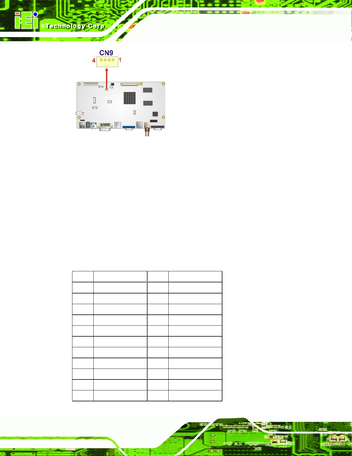
Figure 4-28: IR Sensor Connector Location
4.6.6 LVDS Signal Output Connector
CN Label: CN7
PICOe-6612 5.25” CPU Card
CN Type: 30-pin connector
CN Pinouts:
CN Location:
880H880HTable 4-35
See
881H881HFigure 4-29
See
Use the LVDS signal output connector to connect the LCD panel to a system.
PIN DESCRIPTION PIN DESCRIPTION
1 GND 2 GND
3 TXO3+ 4 TXO3-
5 TXOC+ 6 TXOC-
7 TXO2+ 8 TXO2-
9 TXO1+ 10 TXO1-
11 TXO0+ 12 TXO0-
13 GND 14 GND
15 TXE3+ 16 TXE3-
17 TXEC+ 18 TXEC-
19 TXE2+ 20 TXE2-
21 TXE1+ 22 TXE1-
Page 74
Page 95

PICOe-6612 5.25” CPU Card
23 TXE0+ 24 TXE0-
25 GND 26 GND
27 VDD 28 VDD
29 VDD 30 VDD
Table 4-35: LVDS Signal Output Connector Pinouts
Figure 4-29: LVDS Signal Output Connector Location
NOTE:
The supply voltage (3.3V (Default), 5V or 12V) can be selected via JP5.
4.6.7 OSD and LED Connector
CN Label: CN1
CN Type: 16-pin wafer connector
CN Pinouts:
CN Location:
882H882HTable 4-36
See
883H883HFigure 4-30
See
The OSD and LED connector connects to an external OSD controller.
PIN DESCRIPTION
1 MENU/ENTER
Page 75
Page 96

2 DOWN
3 LEFT
4 UP
5 RIGHT
6 LED_SENSOR
7 SWAP
8 PIP
9 SOURCE
10 LCD ON/OFF
11 VIN1
12 VIN2
13 AUTO/EXIT
14 LED_RED
15 LED_GREEN
PICOe-6612 5.25” CPU Card
16 GND
Table 4-36: OSD and LED Connector Pinouts
Figure 4-30: OSD and LED Connector Location
4.6.8 Power Input Connector
CN Label: CN14
CN Type: 2-pin wafer connector
CN Pinouts:
Page 76
884H884HTable 4-37
See
Page 97

PICOe-6612 5.25” CPU Card
CN Location:
885H885HFigure 4-31
See
The AV-6962 supports one 12V power input connector.
PIN DESCRIPTION
1 +12V Input
2 GND
Table 4-37: Power Output Connector Pinouts (CN15)
Figure 4-31: Power Output Connector Locations
4.6.9 Power Output Connector
CN Label: CN15
CN Type: 2-pin wafer connector
CN Pinouts:
886H886HTable 4-38
See
CN Location:
887H887HFigure 4-32
See
The AV-6962 supports one +5V power output connector.
PIN DESCRIPTION
1 +5V
2 GND
Table 4-38: Power Input Connector Pinouts (CN15)
Page 77
Page 98

Figure 4-32: Power Input Connector Locations
4.6.10 Remote Control Connector
CN Label: CN6
PICOe-6612 5.25” CPU Card
CN Type: 3-pin box header
CN Pinouts:
CN Location:
The remote control connector supports the remote control function.
PIN DESCRIPTION
1 GND
2 VCC
3 Remote Out
888H888HTable 4-39
See
889H889HFigure 4-33
See
Table 4-39: Remote Control Connector Pinouts
Page 78
Page 99

PICOe-6612 5.25” CPU Card
Figure 4-33: Remote Control Connector Location
4.6.11 RS-232 Serial Port Connector
CN Label: COM1
CN Type: 10-pin box header
CN Pinouts:
CN Location:
890H890HTable 4-40
See
891H891HFigure 4-34
See
The 10-pin serial port connector provides a second RS-232 serial communications
channel. The COM1 serial port connector can be connected to external RS-232 serial port
devices.
PIN DESCRIPTION PIN DESCRIPTION
1 NRLSD 6 NCTS
2 NDSR 7 NDTR
3 NRX 8 NRI
4 NRTS 9 GND
5 NTX 10 NC
Table 4-40: RS-232 Serial Port Connector Pinouts
Page 79
Page 100

Figure 4-34: RS-232 Serial Port Connector Location
4.6.12 USB Connector
CN Label: USB1
PICOe-6612 5.25” CPU Card
CN Type: 4-pin header
CN Pinouts:
CN Location:
892H892HTable 4-41
See
893H893HFigure 4-35
See
The 1x4 USB pin connectors each provide connectivity to one USB port. Additional
external USB ports are found on the rear panel. The USB port is used for USB touch
panel.
PIN DESCRIPTION
1 +5V
2 USB3 USB+
4 GND
Table 4-41: USB Connector Pinouts
Page 80
 Loading...