

Page 1

AFL-xxx-CX2 Panel PC
MODEL:
AFL-xxx-CX2
Panel PC with Touch Screen and VIA® EDEN CPU
Gigabit Ethernet, Four USB, Audio, RS-232/422/485, SATA
RoHS Compliant, IP 64 Protection
User Manual
Rev. 1.00 September, 2008
Page i
Page 2
AFL-xxx-CX2 Panel PC
Revision
Date Version Changes
September, 2008 1.00 Initial release
Page ii
Page 3

AFL-xxx-CX2 Panel PC
COPYRIGHT NOTICE
The information in this document is subject to change without prior notice in order to
improve reliability, design and function and does not represent a commitment on the part
of the manufacturer.
In no event will the manufacturer be liable for direct, indirect, special, incidental, or
consequential damages arising out of the use or inability to use the product or
documentation, even if advised of the possibility of such damages.
This document contains proprietary information protected by copyright. All rights are
Copyright
reserved. No part of this manual may be reproduced by any mechanical, electronic, or
other means in any form without prior written permission of the manufacturer.
TRADEMARKS
All registered trademarks and product names mentioned herein are used for identification
purposes only and may be trademarks and/or registered trademarks of their respective
owners.
Page iii
Page 4

AFL-xxx-CX2 Panel PC
Manual Conventions
WARNING!
Warnings appear where overlooked details may cause damage to the equipment or result
in personal injury. Warnings should be taken seriously. Warnings are easy to recognize.
The word “warning” is written as “WARNING,” both capitalized and bold and is followed by
text. The text is the warning message. A warning message is shown below:
WARNING:
This is an example of a warning message. Failure to adhere to warning
messages may result in permanent damage to the AFL-xxx-CX2 or
personal injury to the user. Please take warning messages seriously.
CAUTION!
Cautionary messages should also be heeded to help reduce the chance of losing data or
damaging the AFL-xxx-CX2. Cautions are easy to recognize. The word “caution” is written
as “CAUTION,” both capitalized and bold and is followed. The text is the cautionary
message. A caution message is shown below:
CAUTION:
This is an example of a caution message. Failure to adhere to cautions
messages may result in permanent damage to the AFL-xxx-CX2.
Please take caution messages seriously.
Page iv
Page 5

AFL-xxx-CX2 Panel PC
NOTE:
These messages inform the reader of essential but non-critical information. These
messages should be read carefully as any directions or instructions contained therein can
help avoid making mistakes. Notes are easy to recognize. The word “note” is written as
“NOTE,” both capitalized and bold and is followed by text. The text is the cautionary
message. A note message is shown below:
NOTE:
This is an example of a note message. Notes should always be read.
Notes contain critical information about the AFL-xxx-CX2. Please take
note messages seriously.
Page v
Page 6

AFL-xxx-CX2 Panel PC
Packing List
NOTE:
If any of the components listed in the checklist below are missing,
please do not proceed with the installation. Contact the IEI reseller or
vendor you purchased the AFL-xxx-CX2 from or contact an IEI sales
representative directly. To contact an IEI sales representative, please
send an email to
The items listed below should all be included in the AFL-xxx-CX2 package.
1 x AFL-xxx-CX2
1 x Power adapter
1 x Power cable
1 x External SATA cable
1 x Driver CD
1 x Bluetooth adapter driver CD
Images of the above items are shown in Chapter 3.
sales@iei.com.tw.
Page vi
Page 7

AFL-xxx-CX2 Panel PC
Table of Contents
1 INTRODUCTION.......................................................................................................... 1
1.1 OVERVIEW ................................................................................................................. 2
1.1.1 Model Variations................................................................................................ 3
1.1.2 Applications ....................................................................................................... 3
1.1.3 Standard Features.............................................................................................. 4
1.2 EXTERNAL OVERVIEW ............................................................................................... 4
1.2.1 General Description........................................................................................... 4
1.2.2 Front Panel........................................................................................................ 5
1.2.3 Rear Panel ......................................................................................................... 6
1.2.4 Bottom Panel...................................................................................................... 6
1.3 INTERNAL OVERVIEW................................................................................................. 7
1.4 SPECIFICATIONS ......................................................................................................... 8
1.4.1 Preinstalled Hardware Components.................................................................. 8
1.4.2 System Specifications......................................................................................... 9
1.4.3 Motherboard Specifications............................................................................. 10
1.4.4 Flat Panel Screen Specifications......................................................................11
1.4.4.1 AFL-07A-CX2...........................................................................................11
1.4.4.2 AFL-08AH-CX2........................................................................................11
1.4.4.3 AFL-10A-CX2.......................................................................................... 12
1.4.4.4 AFL-12B-CX2 .......................................................................................... 13
1.4.5 Touch Screen Specifications............................................................................. 13
1.4.6 Bluetooth Module Specifications ..................................................................... 14
1.4.7 Optional HSDPA Module Specifications.......................................................... 15
1.5 DIMENSIONS ............................................................................................................ 15
1.5.1 AFL-07A-CX2 Dimensions .............................................................................. 16
1.5.2 AFL-08AH-CX2 Dimensions............................................................................ 17
1.5.3 AFL-10A-CX2 Dimensions .............................................................................. 18
1.5.4 AFL-12B-CX2 Dimensions .............................................................................. 19
2 MOTHERBOARD....................................................................................................... 20
2.1 INTRODUCTION ........................................................................................................ 21
Page vii
Page 8

2.2 CPU SUPPORT.......................................................................................................... 21
2.3 SYSTEM CHIPSET ..................................................................................................... 21
2.4 GRAPHICS ................................................................................................................ 22
2.5 GIGABIT ETHERNET ................................................................................................. 22
2.6 MEMORY.................................................................................................................. 23
2.7 STORAGE.................................................................................................................. 24
2.7.1 CompactFlash®................................................................................................ 24
2.7.2 Hard Drive....................................................................................................... 25
2.8 BLUETOOTH MODULE.............................................................................................. 26
2.9 HSDPA MODULE (OPTIONAL)................................................................................. 27
2.10 WIRELESS LAN ..................................................................................................... 28
2.11 FRONT PANEL......................................................................................................... 28
2.11.1 LCD Screen .................................................................................................... 28
2.1 1.2 Touch Screen................................................................................................... 29
AFL-xxx-CX2 Panel PC
2.12 INTERNAL PERIPHERAL DEVICE CONNECTORS....................................................... 29
2.12.1 Touch Screen Connector ................................................................................ 30
2.12.2 GPIO Connector............................................................................................ 30
2.12.3 RFID Connector............................................................................................. 31
2.12.4 Front Panel Connectors................................................................................. 31
2.12.5 MCU Program Connector ............................................................................. 32
2.12.6 Keypad Connector ......................................................................................... 32
2.12.7 Backlight Connector ...................................................................................... 33
2.12.8 CPLD Connector ........................................................................................... 33
2.12.9 PS/2 Connector.............................................................................................. 34
2.12.10 VGA Connector............................................................................................ 34
2.12.11 Hard Drive Power Connector...................................................................... 35
2.12.12 CompactFlash® Connector......................................................................... 35
2.12.13 Primary IDE Connector............................................................................... 36
2.12.14 Audio Output Connector.............................................................................. 37
2.12.15 Microphone Input Connector....................................................................... 38
2.12.16 12 V Power Connector................................................................................. 38
2.12.17 COM2 RS-232/422/485 Serial Port Connector........................................... 39
2.12.18 COM1 RS-232 Serial Port Connector ......................................................... 39
2.12.19 Digital Microphone Input Connector .......................................................... 40
2.12.20 SATA Ports ................................................................................................... 40
Page viii
Page 9

AFL-xxx-CX2 Panel PC
2.12.21 Battery Connector........................................................................................ 41
2.12.22 LVDS Connector.......................................................................................... 42
2.12.23 CPU Fan Connector.................................................................................... 42
2.12.24 USB Connectors (Internal).......................................................................... 43
3 INSTALLATION ......................................................................................................... 44
3.1 INSTALLATION PRECAUTIONS................................................................................... 45
3.2 PREINSTALLED COMPONENTS .................................................................................. 45
3.3 INST ALLATION AND CONFIGURATION STEPS............................................................. 46
3.4 UNPACKING.............................................................................................................. 46
3.4.1 Packing List ..................................................................................................... 47
3.4.2 Optional Items.................................................................................................. 48
3.5 COMPACTFLASH
®
CARD INSTALLATION................................................................... 49
3.6 HARD DRIVE INSTALLATION .................................................................................... 50
3.7 AT/A TX MODE SELECTION ..................................................................................... 53
3.7.1 AT Power Mode................................................................................................ 54
3.7.2 ATX Power Mode............................................................................................. 54
3.8 MOUNTING THE SYSTEM.......................................................................................... 54
3.8.1 Wall Mounting.................................................................................................. 55
3.8.2 Arm Mounting .................................................................................................. 57
3.8.3 Panel Mounting................................................................................................ 59
3.8.4 Cabinet and Rack Installation ......................................................................... 62
3.9 BOTTOM PANEL CONNECTORS ................................................................................. 65
3.9.1 LAN Connection............................................................................................... 65
3.9.2 Serial Device Connection ................................................................................ 66
3.9.3 USB Device Connection................................................................................... 67
4 SYSTEM MAINTENANCE ....................................................................................... 68
4.1 SYSTEM MAINTENANCE INTRODUCTION.................................................................. 69
4.2 MOTHERBOARD REPLACEMENT............................................................................... 69
4.3 INTERNAL ALUMINUM COVER REMOVAL................................................................. 69
4.4 MEMORY MODULE REPLACEMENT .......................................................................... 72
4.5 JUMPER SETTINGS.................................................................................................... 74
4.5.1 AT/ATX Power Selection (JP18)...................................................................... 76
4.5.2 Clear CMOS (JP5)........................................................................................... 76
Page ix
Page 10

4.5.3 CompactFlash® Master/Slave Selection (JP8) ................................................ 76
4.5.4 COM1 Pin-9 Setting (JP6)............................................................................... 77
4.5.5 COM2 Settings................................................................................................. 77
4.5.5.1 COM2 Pin-9 Setting (JP6)........................................................................ 77
4.5.5.2 COM2 Mode Select (JP7)......................................................................... 77
4.5.5.3 COM2 RS-422/485 Select (JP15)............................................................. 78
4.5.5.4 Pin-12 Signal Setting (JP8)....................................................................... 78
4.5.6 LCD Voltage Selection (JP4) ........................................................................... 78
4.5.7 Panel Resolution (JP2).................................................................................... 79
4.5.8 Touch Panel Type (J1)...................................................................................... 79
5 BIOS SETUP................................................................................................................ 80
5.1 INTRODUCTION ........................................................................................................ 81
5.1.1 Starting Setup................................................................................................... 81
5.1.2 Using Setup...................................................................................................... 81
AFL-xxx-CX2 Panel PC
5.1.3 Getting Help..................................................................................................... 82
5.1.4 Unable to Reboot After Configuration Changes.............................................. 82
5.1.5 BIOS Menu Bar................................................................................................ 82
5.2 MAIN ....................................................................................................................... 83
5.3 ADVANCED............................................................................................................... 84
5.3.1 CPU Configuration.......................................................................................... 86
5.3.2 IDE Configuration........................................................................................... 87
5.3.2.1 IDE Master, IDE Slave............................................................................. 88
5.3.3 Super IO Configuration.................................................................................... 93
5.3.4 Remote Access Configuration.......................................................................... 95
5.3.5 USB Configuration........................................................................................... 98
5.3.5.1 USB Mass Storage Device Configuration............................................... 100
5.3.6 Power Configuration ..................................................................................... 102
5.3.6.1 ACPI Configuration ................................................................................ 103
5.3.6.2 APM Configuration................................................................................. 104
5.4 PCI/PNP ................................................................................................................ 106
5.5 BOOT ..................................................................................................................... 108
5.5.1 Boot Settings Configuration........................................................................... 109
5.5.2 Boot Device Priority.......................................................................................111
5.5.3 Hard Disk Drives............................................................................................112
Page x
Page 11

AFL-xxx-CX2 Panel PC
5.5.4 Removable Drives...........................................................................................113
5.6 SECURITY................................................................................................................114
5.7 CHIPSET ..................................................................................................................115
5.7.1 Northbridge Configuration.............................................................................116
5.7.2 Southbridge Configuration .............................................................................118
5.8 EXIT........................................................................................................................119
6 DRIVER INSTALLATION....................................................................................... 121
6.1 AVAILABLE SOFTWARE DRIVERS ............................................................................ 122
6.2 DRIVER CD AUTO-RUN.......................................................................................... 122
6.3 CHIPSET DRIVER.................................................................................................... 123
6.4 GRAPHICS DRIVER ................................................................................................. 127
6.5 GIGABIT ETHERNET DRIVER .................................................................................. 130
6.6 AUDIO DRIVER....................................................................................................... 134
6.6.1 BIOS Setup..................................................................................................... 134
6.6.2 Driver Installation ......................................................................................... 134
6.7 TOUCH PANEL DRIVER........................................................................................... 136
6.8 WIRELESS LAN MINI PCI CARD DRIVER.............................................................. 139
6.9 BLUETOOTH DRIVER.............................................................................................. 143
A BIOS OPTIONS ........................................................................................................ 149
B TERMINOLOGY...................................................................................................... 152
C DIGITAL I/O INTERFACE..................................................................................... 156
C.1 INTRODUCTION...................................................................................................... 157
C.2 DIO CONNECTOR PINOUTS ................................................................................... 157
C.3 ASSEMBLY LANGUAGE SAMPLES........................................................................... 158
C.3.1 Enable the DIO Input Function..................................................................... 158
C.3.2 Enable the DIO Output Function.................................................................. 158
D WA TCHDOG TIMER .............................................................................................. 159
E ADDRESS MAPPING .............................................................................................. 162
E.1 DIRECT MEMORY ACCESS (DMA)......................................................................... 163
E.2 INPUT/OUTPUT (IO)............................................................................................... 164
E.3 INTERRUPT REQUEST (IRQ)................................................................................... 166
E.4 MEMORY............................................................................................................... 167
Page xi
Page 12

F COMPATIBILITY..................................................................................................... 168
F.1 COMPATIBLE OPERATING SYSTEMS ........................................................................ 169
F.2 COMPATIBLE PROCESSORS ..................................................................................... 169
F.3 COMPATIBLE MEMORY MODULES.......................................................................... 170
G HAZARDOUS MATERIALS DISCLOSURE....................................................... 171
G.1 HAZARDOUS MATERIALS DISCLOSURE TABLE FOR IPB PRODUCTS CERTIFIED AS
ROHS COMPLIANT UNDER 2002/95/EC WITHOUT MERCURY..................................... 172
H AC'97 AUDIO CODEC ............................................................................................ 175
H.1 INTRODUCTION ..................................................................................................... 176
H.1.1 Accessing the AC’97 CODEC....................................................................... 176
H.1.2 Driver Installation......................................................................................... 176
H.2 SOUND EFFECT CONFIGURATION........................................................................... 177
H.2.1 Accessing the Sound Effects Manager.......................................................... 177
AFL-xxx-CX2 Panel PC
H.2.2 Sound Effect Manager Configuration Options ............................................. 178
Page xii
Page 13

AFL-xxx-CX2 Panel PC
List of Figures
Figure 1-1: AFL-xxx-CX2................................................................................................................2
Figure 1-2: Front View....................................................................................................................5
Figure 1-3: Rear View.....................................................................................................................6
Figure 1-4: Bottom View ................................................................................................................7
Figure 1-5: AFL-xxx-CX2 Internal Overview.................................................................................8
Figure 1-6: AFL-07A-CX2 Dimensions (units in mm)................................................................16
Figure 1-7: AFL-08AH-CX2 Dimensions (units in mm) .............................................................17
Figure 1-8: AFL-10A-CX2 Dimensions (units in mm)................................................................18
Figure 1-9: AFL-12B-CX2 Dimensions (units in mm)................................................................19
Figure 2-1: Gigabit Ethernet........................................................................................................23
Figure 2-2: Memory Module.........................................................................................................24
Figure 2-3: CompactFlash® Slot.................................................................................................25
Figure 2-4: Hard Drive Slot ..........................................................................................................25
Figure 2-5: External SATA Hard Drive........................................................................................26
Figure 2-6: Bluetooth Module......................................................................................................26
Figure 2-7: HSDPA Module..........................................................................................................27
Figure 2-8: Wireless LAN Module ...............................................................................................28
Figure 2-9: AFLMB-CX2-R10 Connector Overview ...................................................................29
Figure 3-1: AFL-07A-CX2 Cover Retention Screws...................................................................49
Figure 3-2: AFL-08AH-CX2 Cover Retention Screws................................................................49
Figure 3-3: AFL-10A-CX2 Cover Retention Screws...................................................................49
Figure 3-4: AFL-12B-CX2 Back Cover Retention Screws.........................................................50
Figure 3-5: CompactFlash® Card Slot Location........................................................................50
Figure 3-6: AFL-12B-CX2 Cover Retention Screws...................................................................51
Figure 3-7: AFL-12B-CX2 Bracket Retention Screws................................................................52
Figure 3-8: AFL-xxx-CX2 Hard Drive Retention Screws...........................................................52
Figure 3-9: AT/ATX Switch Location...........................................................................................53
Figure 3-10: Wall-mounting Bracket...........................................................................................55
Figure 3-11: Chassis Support Screws........................................................................................56
Figure 3-12: Secure the Panel PC...............................................................................................57
Page xiii
Page 14

Figure 3-13: Arm Mounting Screw Holes (AFL-07A-CX2 and AFL-08AH-CX2) ......................58
Figure 3-14: Arm Mounting Screw Holes (AFL-10A-CX2 and AFL-12B-CX2).........................59
Figure 3-15: AFL-07A-CX2 Panel Opening.................................................................................60
Figure 3-16: AFL-08AH-CX2 Panel Opening ..............................................................................60
Figure 3-17: AFL-10A-CX2 Panel Opening.................................................................................61
Figure 3-18: AFL-12B-CX2 Panel Opening.................................................................................61
Figure 3-19: Tighten the Panel Mounting Clamp Screws.........................................................62
Figure 3-20: The Rack/Cabinet Bracket......................................................................................63
Figure 3-21: Secure the Rack/Cabinet Bracket..........................................................................64
Figure 3-22: Install into a Rack/Cabinet .....................................................................................64
Figure 3-23: LAN Connection......................................................................................................65
Figure 3-24: Serial Device Connector.........................................................................................66
Figure 3-25: USB Device Connection.........................................................................................67
Figure 4-1: AFL-07A-CX2 Aluminum Back Cover Retention Screws......................................70
AFL-xxx-CX2 Panel PC
Figure 4-2: AFL-08AH-CX2 Aluminum Back Cover Retention Screws....................................71
Figure 4-3: AFL-10A-CX2 Aluminum Back Cover Retention Screws......................................71
Figure 4-4: AFL-12B-CX2 Aluminum Back Cover Retention Screws......................................72
Figure 4-5: Memory Module.........................................................................................................73
Figure 4-6: DDR2 SO-DIMM Module Installation........................................................................74
Figure 4-7: Jumper Locations.....................................................................................................75
Figure 6-1: Available Drivers.................................................................................................... 123
Figure 6-2: Chipset Driver Icon................................................................................................ 124
Figure 6-3: Chipset Driver Welcome Screen........................................................................... 124
Figure 6-4: Chipset Driver License Agreement...................................................................... 125
Figure 6-5: Chipset Driver List................................................................................................. 125
Figure 6-6: Chipset Driver List................................................................................................. 126
Figure 6-7: Chipset Driver Installed Drivers ........................................................................... 126
Figure 6-8: Chipset Driver Installed Drivers ........................................................................... 127
Figure 6-9: Graphics Driver Installation.................................................................................. 128
Figure 6-10: VGA Driver............................................................................................................ 129
Figure 6-11: Windows Control Panel....................................................................................... 130
Figure 6-12: System Icon.......................................................................................................... 131
Figure 6-13: System Properties................................................................................................ 131
Figure 6-14: Ethernet Controller .............................................................................................. 132
Figure 6-15: Hardware Update Wizard..................................................................................... 132
Page xiv
Page 15

AFL-xxx-CX2 Panel PC
Figure 6-16: Search for LAN Driver.......................................................................................... 133
Figure 6-17: LAN Driver Installation Complete....................................................................... 133
Figure 6-18: Select the Audio CODEC..................................................................................... 134
Figure 6-19: Audio Driver Installation...................................................................................... 135
Figure 6-20: Audio Driver Installation Windows..................................................................... 135
Figure 6-21: InstallShield Wizard Welcome Screen............................................................... 136
Figure 6-22: S-Video Patch Folder........................................................................................... 137
Figure 6-23: Access Startup Folder......................................................................................... 137
Figure 6-24: Start Touch Panel Driver Installation................................................................. 138
Figure 6-25: Windows Logo Testing........................................................................................ 138
Figure 6-26: Create Shortcut Wizard ....................................................................................... 139
Figure 6-27: Software Driver Folder......................................................................................... 140
Figure 6-28: 802.11g Wireless Mini PCI Card Welcome Screen............................................ 140
Figure 6-29: Configuration Tool Selection.............................................................................. 141
Figure 6-30: Optimization Mode............................................................................................... 141
Figure 6-31: Wireless Mini PCI Card Driver Installation Screen........................................... 142
Figure 6-32: InstallShield Wizard Complete Screen............................................................... 142
Figure 6-33: USB2.0 Window.................................................................................................... 143
Figure 6-34: Language Selection............................................................................................. 143
Figure 6-35: Bluetooth InstallShield Wizard........................................................................... 144
Figure 6-36: Bluesoleil License Agreement............................................................................ 144
Figure 6-37: Bluesoleil Custom Settings................................................................................. 145
Figure 6-38: USB 2.0 InstallShield Wizard Welcome Screen ................................................ 146
Figure 6-39: Ready to Install Bluetooth................................................................................... 147
Figure 6-40: USB 2.0 Driver Installed....................................................................................... 148
Page xv
Page 16

AFL-xxx-CX2 Panel PC
List of Tables
Table 1-1: Model Variations...........................................................................................................3
Table 1-2: System Specifications................................................................................................10
Table 1-3: Motherboard Specifications ......................................................................................11
Table 1-4: AFL-07A-CX2 TFT LCD Monitor Specifications.......................................................11
Table 1-5: AFL-08AH-CX2 TFT LCD Monitor Specifications ....................................................12
Table 1-6: AFL-10A-CX2 TFT LCD Monitor Specifications.......................................................12
Table 1-7: AFL-12B-CX2 TFT LCD Monitor Specifications.......................................................13
Table 1-8: Touch Panel Specifications.......................................................................................14
Table 1-9: Bluetooth Module Specifications..............................................................................15
Table 1-10: HSDPA Module Specifications................................................................................15
Table 2-1: Touch Screen Connector...........................................................................................30
Table 2-2: GPIO Connector..........................................................................................................31
Table 2-3: RFID Connector ..........................................................................................................31
Table 2-4: Front Panel Connectors.............................................................................................32
Table 2-5: MCU Program Connector...........................................................................................32
Table 2-6: Keypad Connector......................................................................................................33
Table 2-7: Backlight Connector...................................................................................................33
Table 2-8: CPLD Connector.........................................................................................................34
Table 2-9: PS/2 Connector...........................................................................................................34
Table 2-10: VGA Connector.........................................................................................................35
Table 2-11: Hard Drive Power Connector...................................................................................35
Table 2-12: CompactFlash® Connector.....................................................................................36
Table 2-13: Primary IDE Connector ............................................................................................37
Table 2-14: Audio Output Connector..........................................................................................38
Table 2-15: Microphone Input Connector ..................................................................................38
Table 2-16: 12 V Power Connector..............................................................................................39
Table 2-17: COM2 Serial Port Connector ...................................................................................39
Table 2-18: COM1 Serial Port Connector ...................................................................................40
Table 2-19: Digital Microphone Input Connector ......................................................................40
Table 2-20: SATA Connector.......................................................................................................41
Page xvi
Page 17

AFL-xxx-CX2 Panel PC
Table 2-21: Battery Connector ....................................................................................................41
Table 2-22: LVDS Connector.......................................................................................................42
Table 2-23: CPU Fan Connector..................................................................................................43
Table 2-24: USB Connectors.......................................................................................................43
Table 3-1: Packing List.................................................................................................................48
Table 3-2: Optional Items.............................................................................................................48
Table 4-1: AT/ATX Power Selection............................................................................................76
Table 4-2: Clear CMOS.................................................................................................................76
Table 4-3: CompactFlash® Master/Slave Selection..................................................................76
Table 4-4: COM1 Pin-9 Setting ....................................................................................................77
Table 4-5: COM2 Pin-9 Setting ....................................................................................................77
Table 4-6: COM2 Mode Select .....................................................................................................77
Table 4-7: COM2 Mode Select .....................................................................................................78
Table 4-8: COM2 Mode Select Jumper Settings........................................................................78
Table 4-9: LCD Voltage Setup Jumper Settings........................................................................79
Table 4-10: COM2 Mode Select Jumper Settings......................................................................79
Table 4-11: Touch Panel Type.....................................................................................................79
Table 5-1: BIOS Navigation Keys................................................................................................82
Page xvii
Page 18

AFL-xxx-CX2 Panel PC
BIOS Menus
BIOS Menu 1: Main.......................................................................................................................83
BIOS Menu 2: Advanced..............................................................................................................85
BIOS Menu 3: CPU Configuration...............................................................................................86
BIOS Menu 4: IDE Configuration.................................................................................................87
BIOS Menu 5: IDE Master and IDE Slave Configuration...........................................................88
BIOS Menu 6: Super IO Configuration........................................................................................93
BIOS Menu 7: Remote Access Configuration [Advanced].......................................................95
BIOS Menu 8: USB Configuration...............................................................................................98
BIOS Menu 9: USB Mass Storage Device Configuration....................................................... 100
BIOS Menu 10: Power Configuration....................................................................................... 102
BIOS Menu 11: ACPI Configuration......................................................................................... 103
BIOS Menu 12:Advanced Power Management Configuration.............................................. 104
BIOS Menu 13: PCI/PnP Configuration.................................................................................... 106
BIOS Menu 14: Boot.................................................................................................................. 108
BIOS Menu 15: Boot Settings Configuration.......................................................................... 109
BIOS Menu 16: Boot Device Priority Settings ........................................................................ 111
BIOS Menu 17: Hard Disk Drives ............................................................................................. 112
BIOS Menu 18: Removable Drives........................................................................................... 113
BIOS Menu 19: Security............................................................................................................ 114
BIOS Menu 20: Chipset............................................................................................................. 115
BIOS Menu 21:Northbridge Chipset Configuration................................................................ 116
BIOS Menu 22:Southbridge Chipset Configuration............................................................... 118
BIOS Menu 23:Exit..................................................................................................................... 119
Page xviii
Page 19

AFL-xxx-CX2 Panel PC
Chapter
1
1 Introduction
Page 1
Page 20

1.1 Overview
AFL-xxx-CX2 Panel PC
Figure 1-1: AFL-xxx-CX2
The AFL-xxx-CX2 is a fanless flat panel PC for in-car entertainment or logistics, digital
surveillance, self-service kiosks and home automation. The touch screen interface allows
the AFL-xxx-CX2 to be operated without a keyboard or mouse by simply pressing on the
screen. The AFL-xxx-CX2 comes with an energy efficient VIA EDEN ULV 1.0 GHz
processor and VIA CX700M system chipset, providing all of the features of an everyday
computer, with better energy efficiency.
Multiple forms of connectivity are included. Wireless LAN allows connection to a wireless
network. Gigabit Ethernet allows a 1 Gb/s connection to a wired network when speed is
needed more than the convenience of wireless. USB ports and Bluetooth allow connection
to peripheral devices like PDAs, Bluetooth headsets, Bluetooth GPS modules and any
other device supporting Bluetooth or USB. Finally, a RS-232 port and an RS-232/422/485
serial port allow customized output.
Page 2
Page 21

AFL-xxx-CX2 Panel PC
1.1.1 Model Variations
The AFL-xxx-CX2 models are listed in Table 1-1.
Model LCD CPU Memory Wireless LAN Touch screen
AFL-07A-CX2 7.0”
AFL-08AH-CX2 8.4”
AFL-10A-CX2 10.4”
AFL-12B-CX2 12.1”
Table 1-1: Model Variations
VIA®
Eden™
1.0 GHz
512 MB
DDR2
Yes
Yes
1.1.2 Applications
The AFL-xxx-CX2 all-in-one panel PC is designed for multiple applications. Its durability
and strength makes it an ideal choice for public access computers. Some possible
applications include:
Vehicle Interior device
o Truck PC
o Logistic car PC
o In-car entertainment
General computing
o PC based testing center
o Distance learning
Industrial applications
o Plant environment monitoring system
o Factory automation platform
o Manufacturing shop flow
o Equipment and device control
Home and building automation
o Digital surveillance system
o E-home platform
o Home IA control terminal
Self-Service Kiosk
o Receptionist kiosk in hotel and business premises
Page 3
Page 22

o Self registration terminal in hospital and airport
o Ticket vending machine for transportation use
1.1.3 Standard Features
Some of the standard features of the AFL-xxx-CX2 flat panel PC include:
VIA® Eden 1.0 GHz processor
Rugged mechanism design with ABS/PC case
IP 64 dustproof and waterproof front panel
One 512 MB DDR2 memory module pre-installed
AT/ATX power mode supported
Wireless LAN module and Bluetooth module integrated
Dual GbE LAN support
One CompactFlash® socket
AFL-xxx-CX2 Panel PC
HSDPA module (Optional, for AFL-10A -CX2 and AFL-12B-CX2)
Simple installation process
RoHS compliance
1.2 External Overview
1.2.1 General Description
The AFL-xxx-CX2 is a stylish flat panel PC that comprises of a screen, rear panel, and
bottom panel. An ABS/PC plastic front frame surrounds the front screen. The rear panel
provides screw holes for a wall-mounting bracket compliant with VESA FDMI standard.
The bottom panel provides access to external interface connectors that include Gigabit
LAN, USB 2.0 ports, external SATA connector, serial ports, reset button, power connector
and power switch.
Page 4
Page 23

AFL-xxx-CX2 Panel PC
1.2.2 Front Panel
The front side of the AFL-xxx-CX2 is a flat panel TFT LCD screen surrounded by an
ABS/PC plastic frame.
Figure 1-2: Front View
Page 5
Page 24

1.2.3 Rear Panel
The rear panel provides access to retention screw holes that support the wall mounting.
AFL-xxx-CX2 Panel PC
Refer to
Figure 1-3: Rear View
Figure 1-3.
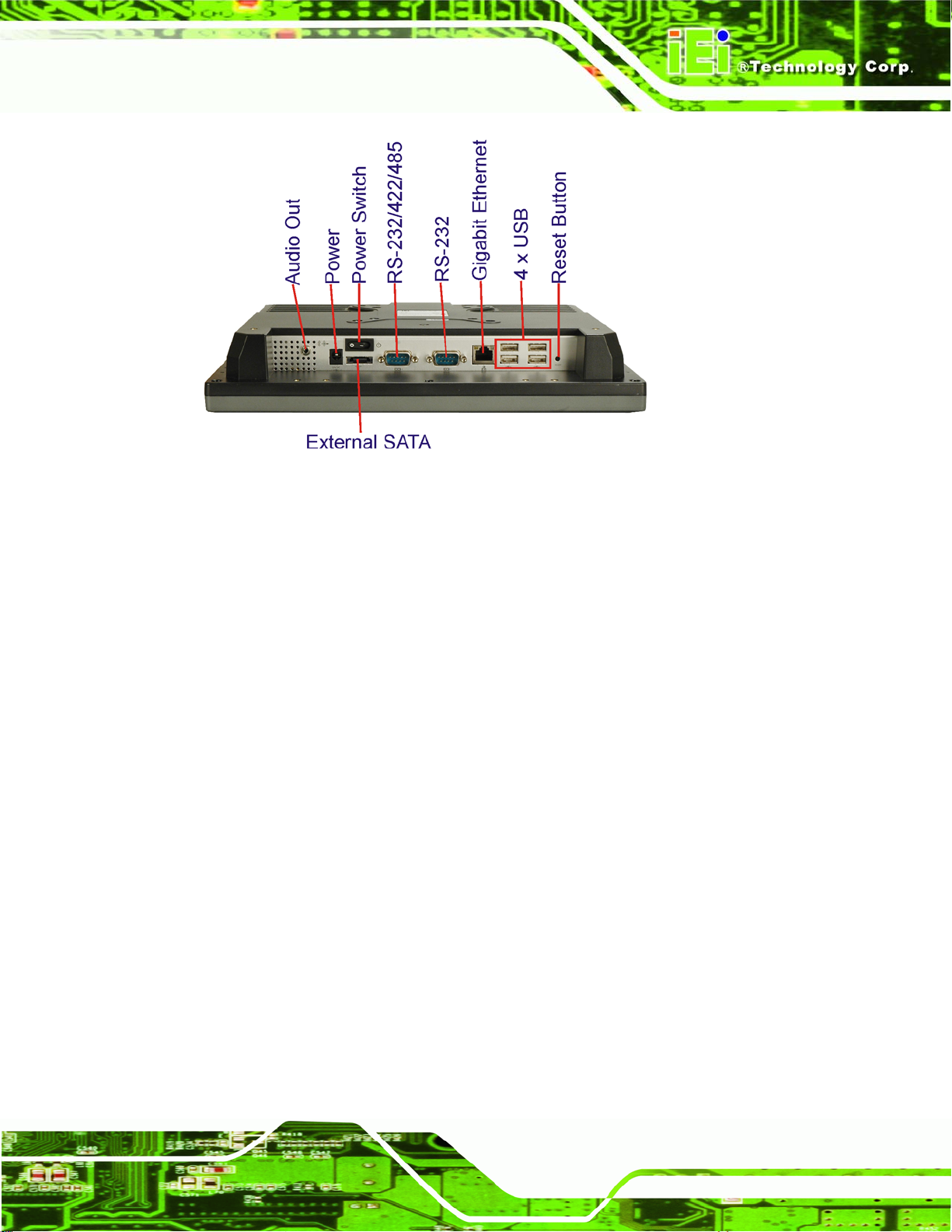
1.2.4 Bottom Panel
The bottom panel of the AFL-xxx-CX2 has the following I/O interfaces (Figure 1-4):
1 x Audio out
1 x External SATA conne ctor
4 x USB 2.0 connectors
1 x Power connector
1 x Power switch
1 x RS-232 serial port
1 x RS-232/422/485 serial port
1 x RJ-45 GbE connector
1 x Reset button
Page 6
Page 25
AFL-xxx-CX2 Panel PC
Figure 1-4: Bottom View
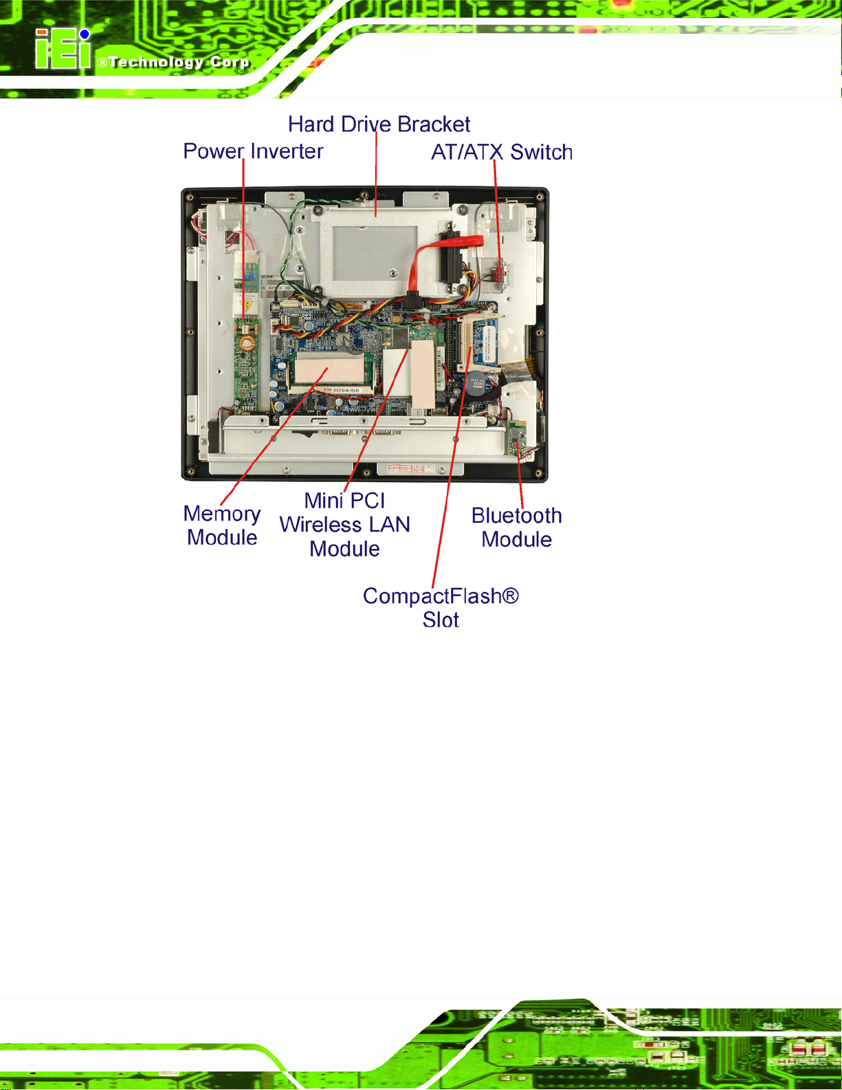
1.3 Internal Overview
The AFL-xxx-CX2 internal components are protected in an aluminum chassis inside the
plastic back cover. An AT/ATX switch i s located on the left of the aluminum chassis inside
the plastic cover. The motherboard, wireless LAN module, Bluetooth module and DDR2
memory module are installed on a metal sheet that protects the rear of the TFT LCD
screen (
screen and the motherboard.
Figure 1-5). Below the metal sheet is a circuit board that is connected to the
Page 7
Page 26
AFL-xxx-CX2 Panel PC
Figure 1-5: AFL-xxx-CX2 Internal Overview
1.4 Specifications
1.4.1 Preinstalled Hardware Components
The AFL-xxx-CX2 flat panel PC has the following preinstalled components:
1 x Motherboard
1 x TFT LCD screen
1 x Touch screen
1 x Inverter
1 x Wireless LAN module
1 x Bluetooth module
Page 8
Page 27
AFL-xxx-CX2 Panel PC
1 x DDR2 memory module
1 x AT/ATX swit ch
1 x HSDPA module (optional)
The technical specifications for some of these components and the system are shown in
the sections below.
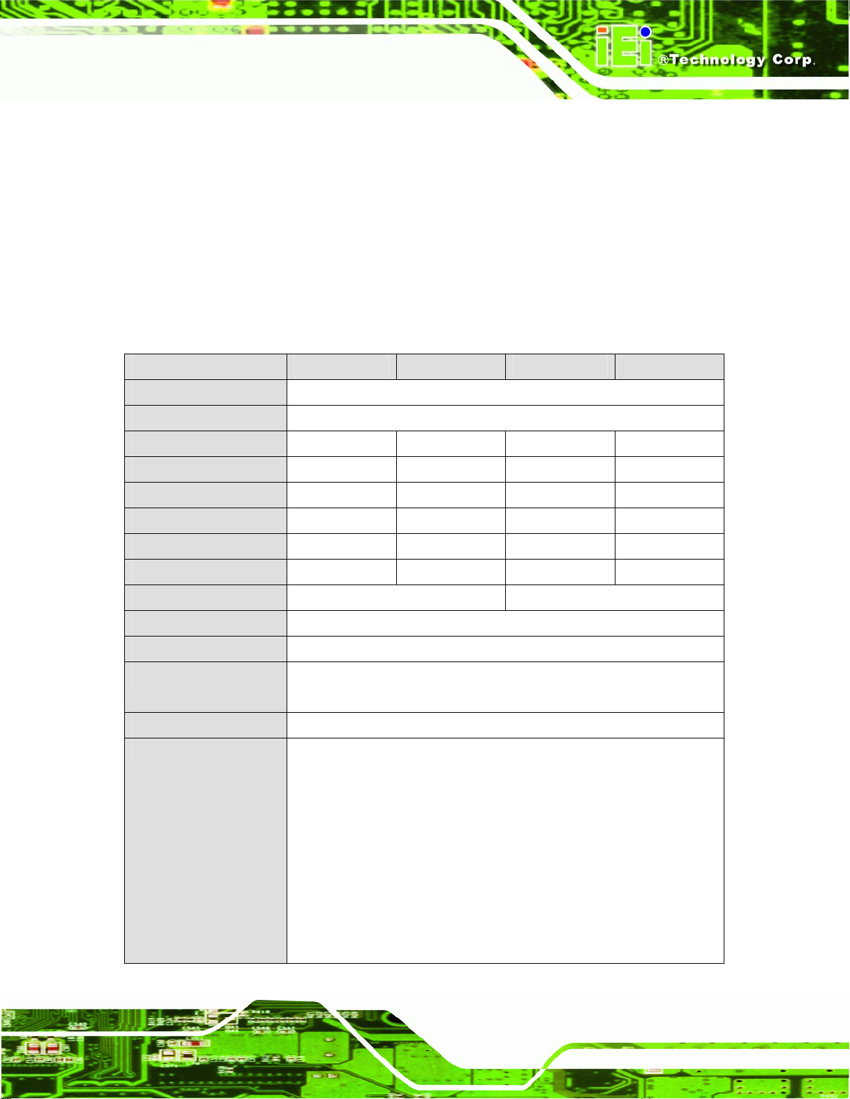
1.4.2 System Specifications
The technical specifications for the AFL-xxx-CX2 are listed in Table 1-2.
SPECIFICATION AFL-07A-CX2 AFL-08AH-CX2 AFL-10A-CX2 AFL-12B-CX2
Front Panel ABS/PC plastic front panel
Chassis Aluminum chassis
LCD Panel 7.0” 8.4” 10.4” 12.1”
Resolution 800 x 480 800 x 600 800 x 600 1024 x 768
Brightness (cd/m2) 350 450 400 400
Contrast Ratio 400:1 500:1 500:1 500:1
Viewing Angle (H-V) 140/100 120/100 120/100 120/100
Backlight MTBF 50000 50000 50000 50000
Touch Screen 4-wire resistive type 5-wire resistive type
SSD CompactFlash®
Audio AMP 1.5 W + AMP 1.5 W (internal speaker)
Extension 1 x Mini PCI (for wireless LAN module)
1 x Bluetooth module (USB interface, Bluetooth v2.0)
HSDPA Module Optional
I/O 1 x Audio out
4 x USB 2.0 ports
1 x Power switch
1 x Power input
1 x External SATA port
1 x RS-232 serial port
1 x RS-232/422/485 serial port
1 x Gigabit Ethernet port
1 x Reset button
Page 9
Page 28

SPECIFICATION AFL-07A-CX2 AFL-08AH-CX2 AFL-10A-CX2 AFL-12B-CX2
Power 12 V, 48 W DC power adapter 12 V, 60 W DC power adapter
Power Consumption 30 W 30 W 36 W 41 W
Mounting Feature Panel, Rack, Wall, Arm, Stand
Operating Temperature 0ºC ~45ºC
Storage Temperature -20ºC ~60ºC
Relative Humidity 10% ~ 80% RH, non-condensing
Dimension (W x H x D) 226 x 140 x 41 234 x 184 x 42 276 x 227 x 50.7 304 x 246 x 56
Net Weight 0.6 kg 0.8 kg 1.4 kg 1.8 kg
Front Panel Protection IP 64 compliant
Safety & EMI CE / FCC / EMC / CB
AFL-xxx-CX2 Panel PC
Table 1-2: System Specifications
1.4.3 Motherboard Specifications
The AFL-xxx-CX2 series come with an AFLMB-CX2-R10 motherboard. The technical
specifications of the motherboard are listed in
Specification AFLMB-CX2-R10
CPU VIA EDEN ULV 1.0 GHz
Chipset VIA CX700M
Display CRT integrated in CX700M
Supports panel resolution from VGA to UXGA (1600 x 1200)
Supports one Dual-Channel / two Single-Channel LVDS panel
Memory Supports one 200-pin 400/533 MHz DDR2 SDRAM SO-DIMM module
up to 1 GB
Extension One mini PCI slot
BIOS AMI BIOS
SSD CFII
Super I/O N/A for legacy free
Audio Realtek ALC888 (High Definition Audio)
LAN 10/100/1000 Base-T RTL8110SC
Table 1-3.
COM 1 x RS-232 serial port
Page 10
1 x RS-232/422/485 serial port
Page 29

AFL-xxx-CX2 Panel PC
Specification AFLMB-CX2-R10
IDE One 44-pin IDE connects to two IDE devices
Touch Screen Controller DMC9000
Power Supply DC 12 V In
Dimensions 102 mm x 186 mm
Table 1-3: Motherboard Specifications
1.4.4 Flat Panel Screen Specifications
The AFL-xxx-CX2 series come with a TFT LCD monitor at the front of the flat panel PC
(see
Figure 1-2). The specifications for the LCD monitor are shown below.
1.4.4.1 AFL-07A-CX2
SPECIFICATION AFL-07A-CX2
Model Data Image FG0700A1DSCWBGL1
Size 7”
Resolution 800 x 480
Active Area (mm) 152.4 x 91.44
Pixel Pitch (mm) 0.1905 x 0.1905
LCD Color 262K
View Angel (H/V) 140/100
Brightness (cd/m2) 350
Contrast Ratio 400:1
Supply Voltage (V) 3.3
Backlight 1 CCFL
Backlight MTBF (hrs.) 50000
Dimensions (WxHxD)(mm) 165 x 104 x 5.5
Table 1-4: AFL-07A-CX2 TFT LCD Monitor Specifications
1.4.4.2 AFL-08AH-CX2
SPECIFICATION AFL-08AH-CX2
Model AUO G084SN05
Page 11
Page 30

SPECIFICATION AFL-08AH-CX2
Size 8.4”
Resolution 800 x 600
Active Area (mm) 170.4 x 127.8
Pixel Pitch (mm) 0.213 x 0.213
LCD Color 262K
View Angel (H/V) 120/100
Brightness (cd/m2) 450
Contrast Ratio 500:1
Supply Voltage (V) 3.3 V
Backlight 2 CCFL
Backlight MTBF (hrs.) 50000
Dimensions (WxHxD)(mm) 165 x 104 x 5.5
AFL-xxx-CX2 Panel PC
Table 1-5: AFL-08AH-CX2 TFT LCD Monitor Specifications
1.4.4.3 AFL-10A-CX2
SPECIFICATION AFL-10A-CX2
Model Toshiba LTA104D182F
Size 10.4”
Resolution 800 x 600
Active Area (mm) 211.2 x 158.4
Pixel Pitch (mm) 0.264 x 0.264
LCD Color 262K
View Angel (H/V) 120/100
Brightness (cd/m2) 400
Contrast Ratio 500:1
Supply Voltage (V) 3.3 V
Backlight 2 CCFL
Backlight MTBF (hrs.) 50000
Dimensions (WxHxD)(mm) 242 x 178.45 x 13.2
Table 1-6: AFL-10A-CX2 TFT LCD Monitor Specifications
Page 12
Page 31
AFL-xxx-CX2 Panel PC
1.4.4.4 AFL-12B-CX2
SPECIFICATION AFL-12B-CX2
Model Toshiba LTA121C50F
Size 12.1”
Resolution 1024 x 768
Active Area (mm) 245.76 x 184.32
Pixel Pitch (mm) 0.24 x 0.24
LCD Color 262K
View Angle (H/V) 120/100
Brightness (cd/m2) 400
Contrast Ratio 500:1
Supply Voltage (V) 3.3 V
Backlight 2 CCFL
Backlight MTBF (hrs.) 50000
Dimensions (WxHxD)(mm) 278.3 x 209.0 x 12.0
Table 1-7: AFL-12B-CX2 TFT LCD Monitor Specifications
1.4.5 Touch Screen Specifications
The AFL-xxx-CX2 series come with an analog resistive type touch panel. Table 1-8 lists
the touch panel specifications.
SPECIFICATION AFL-07A-CX2 AFL-08AH-CX2 AFL-10A-CX2 AFL-12B-CX2
Model 75200-107040
4C-RS
Type Analog Resistive Type Touch Panel
Wire Type 4-wire 5-wire
Viewing Area (mm) 154.90 x 93.94 130.75 x 173.38 219.8 x 166.8 188.0 x 250.0
Active Area (mm) 152.40 x 91.44 127.78 x 170.38 212.1 x 159.3 185.0 x 246.0
Total Transmission 78%
75200-1084403B
-01-RS
75200-1104502
A-RS
75200-1121505
B-RS
Maximum Voltage DC 7 V
Connector Type FPC.
Operating Temperature -10°C ~ 60°C -10°C ~ 50°C
Page 13
Page 32

SPECIFICATION AFL-07A-CX2 AFL-08AH-CX2 AFL-10A-CX2 AFL-12B-CX2
Operating Humidity 20% ~ 90% RH
Storage Temperature -20°C ~ 70°C
Storage Humidity 20% ~ 90% RH
AFL-xxx-CX2 Panel PC
Dimensions 165 x 104 x 1.4 145.5 x 188 x 2.1 238.8x 188.7 x
2.6
204 x 268 x 2.1
Table 1-8: Touch Panel Specifications
1.4.6 Bluetooth Module Specifications
The AFL-xxx-CX2 series are all integrated with a Bluetooth module. The Bluetooth module
enables the transmission between various peripheral devices through a Bluetooth network.
The peripheral devices may include:
Headsets
Barcode readers
PDA
Printers
Cell phones
The technical specifications of the Bluetooth module are listed in
Table 1-9.
Page 14
Specification Bluetooth Module
Standard Bluetooth v2.0
Frequency Band 2.402GHz~2.480GHz unlicensed ISM band
Modulation Method GFSK for 1 Mb/s
π/4-DQPSK for 2 Mb/s
8-DPSK for 3 Mb/s
Spread Spectrum FHSS (Frequency Hopping Spread Spectrum)
RF Output Power Class 2 (under 4dBm)
Antenna Terminal 50 Ohms
DC Power DC 3.3 V or DC 5 V
I/O Interface USB 2.0 interface
Two GPIO Interface LED link indicator interface
Dimensions 35 mm x 11 mm
Page 33
AFL-xxx-CX2 Panel PC
Specification Bluetooth Module
Operating System Windows XP, Windows 2000, Windows 98SE, Windows Me
Table 1-9: Bluetooth Module Specifications
1.4.7 Optional HSDPA Module Specifications
The HSDPA module is one of the OEM options for the AFL-xxx-CX2 series. The technical
specifications of the HSDPA module are listed in
Specification
EDG/HSDPA/GSM Air Interface Quad-band operation GSM850, EGSM 900, DCS 1800, PCS
EHSDPA/HSDPA (PS) Feature
Set
HSDPA Module
1900
GSM Power Class 4 (2 W) for 850/900 bands
GSM Power Class 1 (1 W) for 1800/1900 bands
EDFE class E2 (+27dBm in 850/900 bands,
+26dBm in 1800/1900 bands)
GSM/HSDPA Rel ’97; PCS 1900 Rel ’98; EHSDPA Rel ’99
compliant
HSDPA Class 10, coding schemes 1-4
EDGE Class 10, Multi-slot classes 1-9
HSDPA/EHSDPA Class B type 1 MT
Link Adaptation
Incremental redundancy (IR)
Table 1-10.
USB Interface USB 2.0 +5 V DC
SIM Card Interface 3.0 V interface
Temperature -30°C ~ +65°C
Humidity Up to 95%, non-condensing
Dimensions 109.3 mm x 42.7 mm x 17.7 mm
Operating System Windows 2000/XP Home/XP Professional
Table 1-10: HSDPA Module Specifications
1.5 Dimensions
The dimensions of all the AFL-xxx-CX2 models are shown in the subsections below.
Page 15
Page 34

1.5.1 AFL-07A-CX2 Dimensions
The dimensions of the AFL-07A-CX2 are shown in Figure 1-8 below.
AFL-xxx-CX2 Panel PC
Page 16
Figure 1-6: AFL-07A-CX2 Dimensions (units in mm)
Page 35

AFL-xxx-CX2 Panel PC
1.5.2 AFL-08AH-CX2 Dimensions
The dimensions of the AFL-08AH-CX2 are shown in Figure 1-8 below.
Figure 1-7: AFL-08AH-CX2 Dimensions (units in mm)
Page 17
Page 36

1.5.3 AFL-10A-CX2 Dimensions
The dimensions of the AFL-10A-CX2 are shown in Figure 1-8 below.
AFL-xxx-CX2 Panel PC
Page 18
Figure 1-8: AFL-10A-CX2 Dimensions (units in mm)
Page 37

AFL-xxx-CX2 Panel PC
1.5.4 AFL-12B-CX2 Dimensions
The dimensions of the AFL-12B-CX2 are shown in Figure 1-9 below.
Figure 1-9: AFL-12B-CX2 Dimensions (units in mm)
Page 19
Page 38

AFL-xxx-CX2 Panel PC
Chapter
2
2 Motherboard
Page 20
Page 39

AFL-xxx-CX2 Panel PC
2.1 Introduction
The AFL-xxx-CX2 contains the AFLMB-CX2-R10 motherboard. The motherboard is the
heart of any computer and is responsible for transmitting, receiving and processing data
as well as driving the different onboard devices. This chapter gives a brief introduction to
the AFLMB-CX2-R10 motherboard.
2.2 CPU Support
The AFLMB-CX2-R10 motherboard comes with a preinstalled VIA EDEN ULV 1.0 GHz
CPU. The specifications of the EDEN processor are shown below.
1.0 GHz clock speed
Full x86 Operating System and software application compatibility
VIA V4 Bus up to 800 MHz FSB
16 pipeline stages
Efficiency enhanced 128 KB full-speed exclusive L2 cache with 32-way
associativity
Sophisticated branch prediction mechanism
MMX, SSE, SSE2 & SSE3 instruction sets
Full-speed FPU
IO/APIC support
90nm SOI (Silicon-on-Insulator) process technology
x86 processor die (30 mm
Compact VIA nanoBGA2 package (21 mm x 21 mm)
AES Encryption
Secure Hash SHA-1 and SHA-256
Two Quantum-based Random Number Generators
NX Execute Protection
2.3 System Chipset
The AFLMB-CX2-R10 motherboard has a preinstalled VIA CX700M system chipset. The
2
)
system chipset features are listed below.
533 MB/s Front Side Bus
Page 21
Page 40

Supports up to 2.0 GB DDR2 533/400 MHz or DDR 400/333/266 MHz
SDRAM
Integrated VIA UniChrome Pro Graphics
Chromotion™ video engine
MPEG-2 Decoder
Video De-blocking
Adaptive De-Interlace
DuoView+™
Optimized Unified memory Architecture (UMA)
200 MHz Graphics Engine Clock with separated 128-bit data p aths
128-bit 2D and 3D Graphics engine
Multi-configuration LVDS/DVI transmitter
Support for VIA Vinyl HD Audio
Serial ATA support for up to 2 devices
AFL-xxx-CX2 Panel PC
Parallel ATA133/100/6 6 support for up to 2 devices
Support for up to 6 USB 2.0 ports
2.4 Graphics
The VIA CX700M utilizes the VIA UniChrome™ Pro Integrated Graphics Processor (IGP)
ensuring optimal performance for all multimedia, entertainment, and productivity
applications. The graphics processor features are listed below.
With a 200 MHz 2D/3D graphics engine
128-bit data paths for pixel data flow
Texture/command access
Chromotion™ video engine raises the bar for digital entertainment support
MPEG-2, MPEG-4 and WMV9 decoding integrated
Flawless digital video playback with ultra-low CPU-utilization
Adaptive De-Interlacing and Video Deblocking advanced rend ering tools
Ensure clearer playback of digital content on all display devices
2.5 Gigabit Ethernet
A highly integrated and cost-effective single-chip, fast Realtek RTL8110SC GbE controller
is interfaced through first the PCI bus to the CPU and system chipset.
Page 22
Page 41

AFL-xxx-CX2 Panel PC
Figure 2-1: Gigabit Ethernet
The Realtek RTL8110SC controller provides 10 Mb/s, 100 Mb/s or 1000 Mb/s Ethernet
connectivity to the AFLMB-CX2-R10. Some of the Gigabit Ethernet controller
specifications are shown below.
Integrated 10/100/1000 transceiver
Auto-Negotiation with Next Page capability
Supports PCI rev.2.3, 32-bit, 33/66 MHz
Supports CLKRUNB and MiniPCI v1.0
Supports pair swap/polarity/skew correction
Crossover Detection & Auto-Correction
Wake-on-LAN and remote wake-up support
Microsoft® NDIS5 Checksum Offload (IP, TCP, UDP) and largesend offload
Supports Full Duplex flow control (IEEE 802.3x)
Fully compliant with IEEE 802.3, IEEE 802.3u, IEEE 802.3ab
Supports IEEE 802.1P Layer 2 Priority Encoding
Supports IEEE 802.1Q VLAN tagging
Serial EEPROM
3.3 V signaling, 5 V PCI I/O tolerant
Transmit/Receive FIFO (8K/64K) support
Supports power down/link down power saving
Supports PCI Message Signaled Interrupt (MSI)
2.6 Memory
support
The VIA CX700M in the AFL-xxx-CX2 contains an internal DDR2 controller. The DDR2
controller has the following features:
Low-latency, high-bandwidth
Page 23
Page 42

400 MHz or 533 MHz 128-bit DDR2 SDRAM controller
Supports one un-buffered DDR2 SO-DIMM
Each SO-DIMM has a maximum capacity of 1.0 GB
The DDR2 controller on the processor is interfaced to one SO-DIMM socket on the
AFL-xxx-CX2.
AFL-xxx-CX2 Panel PC
Figure 2-2: Memory Module
2.7 Storage
There following storage options are available:
CompactFlash®
SATA hard drive
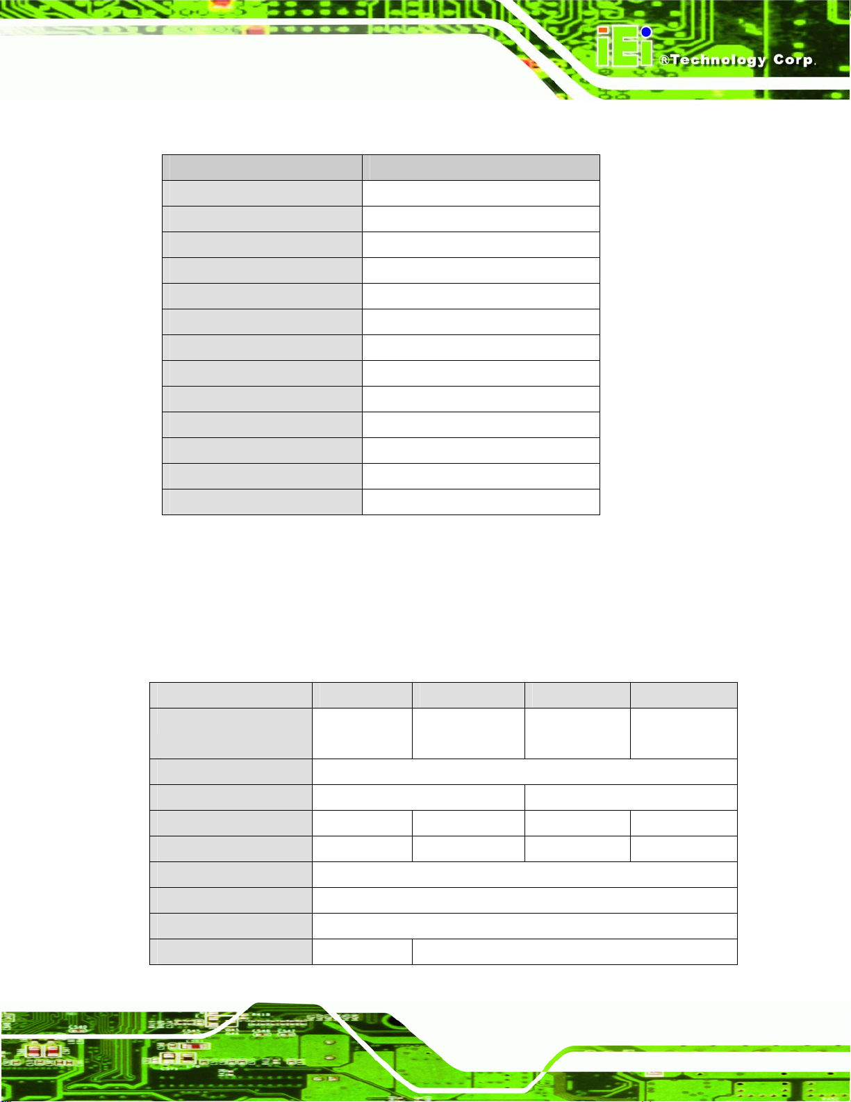
2.7.1 CompactFlash
The CompactFlash® socket supports standard CompactFlash® Type I and
CompactFlash® Type II cards. The chipset flash interface is multiplexed with an IDE
interface and can be connected to an array of industry standard NAND Flash or NOR
Flash devices. The CompactFlash® slot location is shown below.
®
Page 24
Page 43
AFL-xxx-CX2 Panel PC
Figure 2-3: CompactFlash® Slot
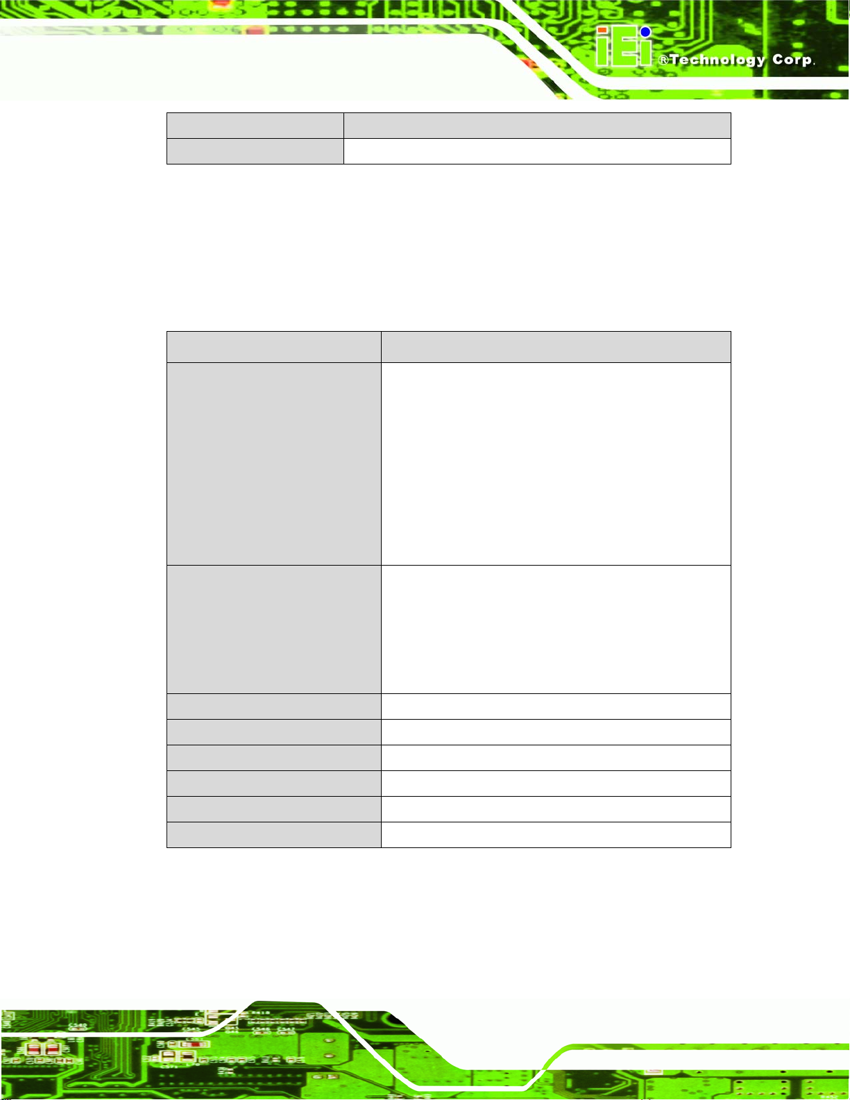
2.7.2 Hard Drive
The AFL-xxx-CX2 supports a single SATA or IDE hard drive. This hard drive is installed
internally and connected to the SATA port or IDE connector on the AFLMB-CX2-R10
motherboard. A second SATA connector is implemented externally through an eSATA
connector.
Figure 2-4: Hard Drive Slot
Page 25
Page 44
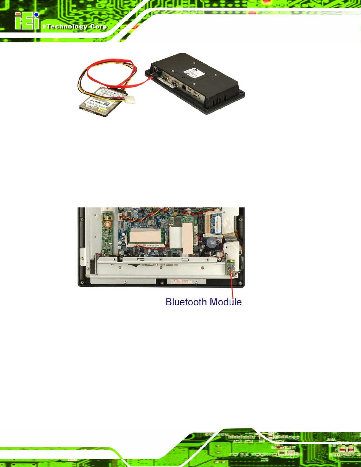
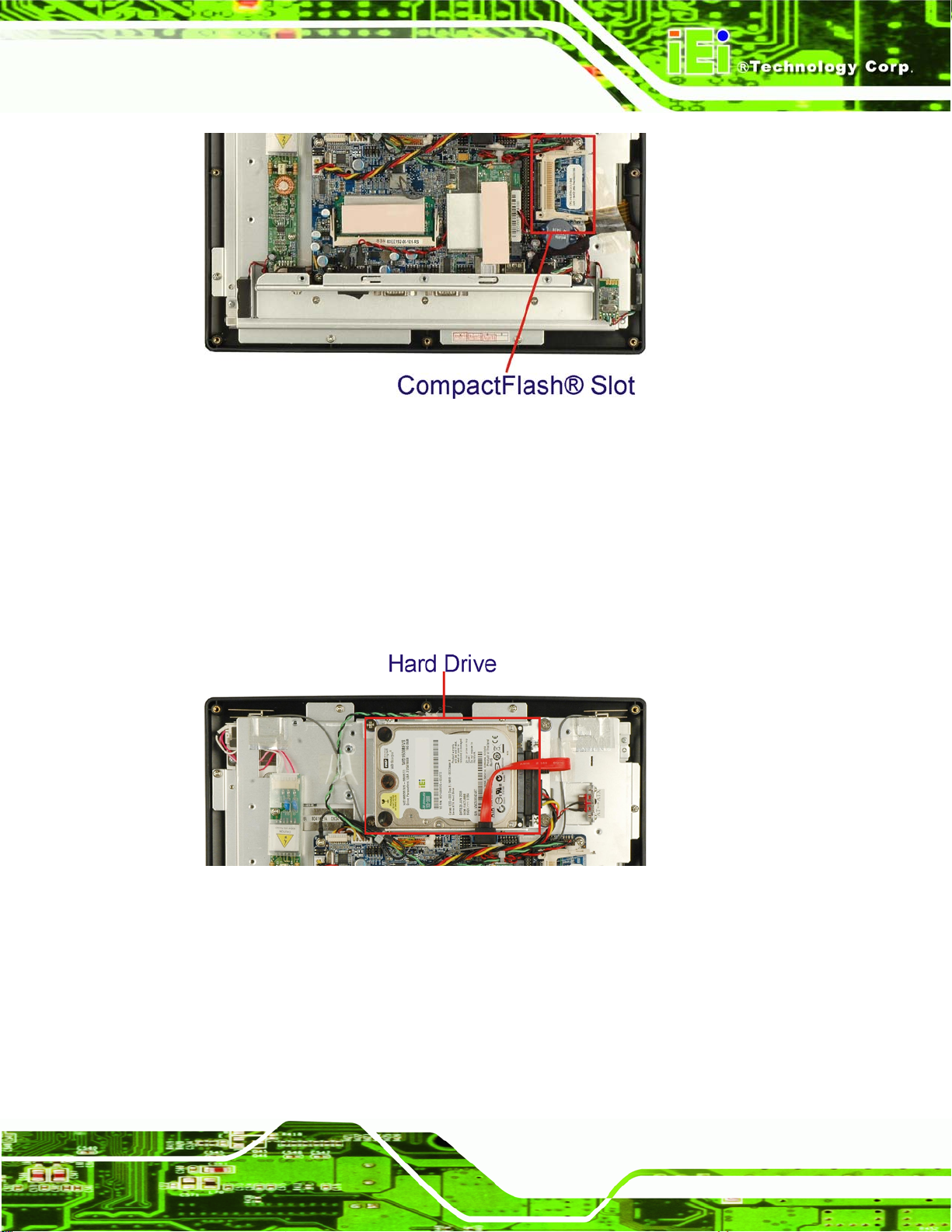
Figure 2-5: External SATA Hard Drive
2.8 Bluetooth Module
The AFL-xxx-CX2 are all integrated with a Bluetooth module. The Bluetooth module
enables the transmission between various peripheral devices through a Bluetooth
network.
AFL-xxx-CX2 Panel PC
Page 26
Figure 2-6: Bluetooth Module
Bluetooth enabled peripheral devices include:
Headsets
Barcode readers
PDAs
Printers
Cell phones
Keyboards and mice
Page 45

AFL-xxx-CX2 Panel PC
Some of the major features of the Bluetooth module are listed below:
Bluetooth v2.0 compliant
Uses 2.402 GHz – 2.480 GHz unlicensed ISM band
Class 2 output power (under 4 dBm)
USB 2.0 interface
2.9 HSDPA Module (Optional)
The HSDPA module is one of the OEM options for the AFL-10A-CX2 and AFL-12B-CX2.
Figure 2-7: HSDPA Module
The HSDPA module connects to 3G and 3.5G cellular networks. The connectivity
provided by the HSDPA module allows the AFL-xxx-CX2 to connect through the Internet
to remote networks, allowing the AFL-xxx-CX2 to send and receive from wherever there is
cellular coverage.
Page 27
Page 46

2.10 Wireless LAN
The IEEE 802.11a/b/g compliant wireless module is pre-installed in the system and
provides wireless connectivity at up to 54 Mb/s. The wireless module is interfaced to the
system chipset through the Mini PCI slot.
AFL-xxx-CX2 Panel PC
Figure 2-8: Wireless LAN Module
Some of the features of the wireless module are listed below.
Compliant with IEEE 802.11a, 802.11b and 802.11g standards
PCI interface (via the Mini PCI slot)
Ralink RT2561 wireless LAN controller
2.11 Front Panel
The front panel of the AFL-xxx-CX2 consists of an LCD monitor and a touch screen panel.
2.11.1 LCD Screen
The AFL-xxx-CX2 comes with a TFT LCD monitor. The tough construction of the TFT
monitor allows the AFL-xxx-CX2 to withstand the conditions it is likely to be exposed to
during regular use. Some of the specifications of the TFT monitors are shown below:
Page 28
Pixel pitch of 0.297 mm or less
700:1 contrast ratio or better
300 cd/m
2
or greater
Page 47

AFL-xxx-CX2 Panel PC
8 msec optical response time or less
o
0
C to 50oC operating temperature
2.11.2 Touch Screen
The touch screen panel on the AFL-xxx-CX2 allows complete user interaction without the
need for a keyboard or mouse. Some of the features of the touch panel are listed below.
5-wire analog resistive type
78% transmission
Control chipset built onto the motherboard
-10
7 V maximum voltage
o
C to 50oC operating temperature
2.12 Internal Peripheral Device Connectors
The peripheral device connectors listed below are located on the AFLMB-CX2-R10
motherboard.
Figure 2-9 shows the overview of the internal connectors.
1 x Audio connector
1 x Inverter connector
1 x LCD interface connector
1 x LED connector
1 x Power switch connector
1 x Touch screen connector
Figure 2-9: AFLMB-CX2-R10 Connector Overview
Page 29
Page 48

2.12.1 Touch Screen Connector
CN Label: JP1
AFL-xxx-CX2 Panel PC
CN Type:
CN Location:
CN Pinouts:
9-pin connector
Figure 2-9
See
Table 2-1
See
The touch screen connector connects to the touch screen on the front panel of the
AFL-xxx-CX2.
PIN DESCRIPTION
1 X+
2 X-
3 Y+
4 SENSE
5 X+
6 X-
7 Y+
8 Y-
9 GND
Table 2-1: Touch Screen Connector
2.12.2 GPIO Connector
CN Label: JP2
CN Type:
CN Location:
CN Pinouts:
The GPIO connector is connected to external devices and can be programmed for
external machine control. As standard, the GPIO connector is not used in the
AFL-xxx-CX2, but is still functional.
4-pin connector
Figure 2-9
See
Table 2-2
See
Page 30
Page 49

AFL-xxx-CX2 Panel PC
PIN DESCRIPTION
1 +5 V
2 GND
3 OUT0
4 INT0
Table 2-2: GPIO Connector
2.12.3 RFID Connector
CN Label: JP3
CN Type:
CN Location:
CN Pinouts:
10-pin connector
Figure 2-9
See
Table 2-3
See
The RFID connector can be connected to an RFID connector. As standard, the RFID
connector is not used in the AFL-xxx-CX2, but is still functional.
PIN DESCRIPTION PIN DESCRIPTION
1 +5 V 2 +5 V
3 GND 4 MCU_UR
5 RX 6 AUTO_CLK
7 TX 8 AUTO_DATA
9 GND 10 GND
Table 2-3: RFID Connector
2.12.4 Front Panel Connectors
CN Label: JP8
CN Type:
CN Location:
CN Pinouts:
10-pin connector (first 8 pins for front panel)
Figure 2-9
See
Table 2-4
See
Page 31
Page 50

The front panel connectors connect to the buttons and indicators on the front panel. These
include the power and reset buttons, and the hard drive and power LEDs.
PIN DESCRIPTION PIN DESCRIPTION
1 Power LED + 2 HDDLED+
3 Power LED - 4 HDDLED-
5 RESET_SW+ 6 PWRBT_SW+
7 RESET_SW- 8 PWRBT_SW-
Table 2-4: Front Panel Connectors
2.12.5 MCU Program Connector
CN Label: JP16
AFL-xxx-CX2 Panel PC
CN Type:
CN Location:
CN Pinouts:
12-pin connector (5 pins for MCU program connector)
Figure 2-9
See
Table 2-5
See
The MCU program connector is for MCU program control.
PIN DESCRIPTION
1 MCLR
3 +5 V
5 GND
7 ICSPCLK
9 ICSPDAT
Table 2-5: MCU Program Connector
2.12.6 Keypad Connector
Page 32
CN Label: JP16
CN Type:
CN Location:
CN Pinouts:
12-pin connector (6 pins for keypad connector)
See
See
Figure 2-9
Table 2-6
Page 51

AFL-xxx-CX2 Panel PC
The keypad connector connects to an numeric keypad for access control systems.
PIN DESCRIPTION
2 VOL+
4 VOL-
6 BRIGHT+
8 BRIGHT-
10 LCD ON_OFF
12 GND
Table 2-6: Keypad Connector
2.12.7 Backlight Connector
CN Label: CN1
CN Type:
CN Location:
CN Pinouts:
6-pin box header
Figure 2-9
See
Table 2-7
See
The backlight connector provides power for the LCD panel backlight.
PIN DESCRIPTION PIN DESCRIPTION
1 12 V 2 12 V
3 BLON 4 ADJ
5 GND 6 GND
Table 2-7: Backlight Connector
2.12.8 CPLD Connector
CN Label: CN2
CN Type:
6-pin connector
Figure 2-9
CN Location:
CN Pinouts:
See
See
Table 2-8
The CPLD connector connects to a complex programmable logic device.
Page 33
Page 52

PIN DESCRIPTION PIN DESCRIPTION
1 3.3 V 2 TDO
3 TDI 4 TMS
5 TCK 6 GND
Table 2-8: CPLD Connector
2.12.9 PS/2 Connector
CN Label: CN3
AFL-xxx-CX2 Panel PC
CN Type:
CN Location:
CN Pinouts:
6-pin box header
Figure 2-9
See
Table 2-9
See
The PS/2 connector can be connected to a PS/2 mouse and PS/2 keyboard.
PIN DESCRIPTION
1 VCC
2 MOUSE DATA
3 MOUSE CLK
4 KEYBOARD DATA
5 KEYBOARD CLK
6 GND
Table 2-9: PS/2 Connector
2.12.10 VGA Connector
Page 34
CN Label: CN5
CN Type:
CN Location:
CN Pinouts:
10-pin box header
Figure 2-9
See
Table 2-10
See
The VGA connector can connect to an external monitor.
Page 53

AFL-xxx-CX2 Panel PC
PIN DESCRIPTION PIN DESCRIPTION
1 RED 2 DDCDAT
3 GREEN 4 DDCCLK
5 BLUE 6 GND
7 VSYNC 8 GND
9 HSYNC 10 GND
Table 2-10: VGA Connector
2.12.11 Hard Drive Power Connector
CN Label: CN9
CN Type:
CN Location:
CN Pinouts:
4-pin box header
Figure 2-9
See
Table 2-11
See
The hard drive power connector provides power to an hard drive installed in the
AFL-xxx-CX2. The hard drive power connector is specifically intended to be used with an
installed SATA hard drive.
PIN DESCRIPTION PIN DESCRIPTION
1 +5 V 2 GND
3 GND 4 +12 V
Table 2-11: Hard Drive Power Connector
2.12.12 CompactFlash® Connector
CN Label: CN10
CN Type:
CN Location:
CN Pinouts:
CompactFlash® connector
Figure 2-9
See
Table 2-12
See
The CompactFlash® slot allows a Type I/II CompactFlash® card to be installed in the
AFL-xxx-CX2.
Page 35
Page 54

PIN DESCRIPTION PIN DESCRIPTION
1 GROUND 26 CARD DETECT1
2 D3 27 D11
3 D4 28 D12
4 D5 29 D13
5 D6 30 D14
6 D7 31 D15
7 CS1# 32 CS3#
8 N/C 33 N/C
9 N/C 34 IOR#
10 N/C 35 IOW#
11 N/C 36 PULL HIGH
12 N/C 37 IRQ15
13 VCC 38 VCC
AFL-xxx-CX2 Panel PC
14 N/C 39 MASTER/SLAVE
15 N/C 40 N/C
16 N/C 41 RESET#
17 N/C 42 IORDY
18 A2 43 N/C
19 A1 44 N/C
20 A0 45 ACTIVE#
21 D0 46 PDIAG#
22 D1 47 D8
23 D2 48 D9
24 N/C 49 D10
25 CARD DETECT2 50 GROUND
Table 2-12: CompactFlash® Connector
2.12.13 Primary IDE Connector
Page 36
CN Label: CN11
CN Type:
CN Location:
44-pin box header
Figure 2-9
See
Page 55
AFL-xxx-CX2 Panel PC
CN Pinouts:
The primary IDE connector connects to a hard drive. The primary IDE connector provides
power to the hard drive and the data connection.
PIN DESCRIPTION PIN DESCRIPTION
1 RESET# 2 GROUND
3 DATA 7 4 DATA 8
5 DATA 6 6 DATA 9
7 DATA 5 8 DATA 10
9 DATA 4 10 DATA 11
11 DATA 3 12 DATA 12
13 DATA 2 14 DATA 13
15 DATA 1 16 DATA 14
See
Table 2-13
17 DATA 0 18 DATA 15
19 GROUND 20 N/C
21 IDE DRQ 22 GROUND
23 IOW# 24 GROUND
25 IOR# 26 GROUND
27 IDE CHRDY 28 GROUND
29 IDE DACK 30 GROUND-DEFAULT
31 INTERRUPT 32 N/C
33 SA1 34 N/C
35 SA0 36 SA2
37 HDC CS0# 38 HDC CS1#
39 HDD ACTIVE# 40 GROUND
41 +5 V 42 +5 V
43 GND 44 N/C
Table 2-13: Primary IDE Connector
2.12.14 Audio Output Connector
CN Label: CN12
Page 37
Page 56

AFL-xxx-CX2 Panel PC
CN Type:
CN Location:
CN Pinouts:
4-pin connector
Figure 2-9
See
Table 2-14
See
The audio output connector connects to speakers.
PIN DESCRIPTION PIN DESCRIPTION
1 OUTL 2 GND
3 GND 4 OUTR
Table 2-14: Audio Output Connector
2.12.15 Microphone Input Connector
CN Label: CN13
CN Type:
CN Location:
4-pin connector
Figure 2-9
See
Table 2-15
CN Pinouts:
See
The microphone input connector connects to a microphone for audio input.
PIN DESCRIPTION PIN DESCRIPTION
1 INL 2 GND
3 GND 4 INR
Table 2-15: Microphone Input Connector
2.12.16 12 V Power Connector
CN Label: CN14
CN Type:
CN Location:
CN Pinouts:
3-pin box header
Figure 2-9
See
Table 2-16
See
Page 38
The 12 V power connector provides 12 V of power to connected devices.
Page 57

AFL-xxx-CX2 Panel PC
PIN DESCRIPTION
1 GND
2 GND
3 12 V
Table 2-16: 12 V Power Connector
2.12.17 COM2 RS-232/422/485 Serial Port Connector
CN Label: CN16
CN Type:
CN Location:
CN Pinouts:
DB-9 male
Figure 2-9
See
Table 2-17
See
The COM2 serial port connector provides an RS-232, RS-422 or RS-485 data connection
to an attached device.
PIN RS-232 mode RS-422 mode RS-485 mode
1 DCD2 TX- Data-
2 RX2 TX+ Data+
3 TX2
4 DTR2
5 GND
6 DSR2 RX-
7 RTS2 RX+
8 CTS2
9 RI2
Table 2-17: COM2 Serial Port Connector
2.12.18 COM1 RS-232 Serial Port Connector
CN Label: CN17
CN Type:
CN Location:
DB-9 male
Figure 2-9
See
Page 39
Page 58
See
CN Pinouts:
Table 2-18
AFL-xxx-CX2 Panel PC
The COM1 serial port connector provides an RS-232 data connection to attached devices.
PIN DESCRIPTION
1 DCD1
2 RX1
3 TX1
4 DTR1
5 GND
6 DSR1
7 RTS1
8 CTS1
9 RI1
Table 2-18: COM1 Serial Port Connector
2.12.19 Digital Microphone Input Connector
CN Label: DMIC_1
CN Type:
CN Location:
CN Pinouts:
The digital microphone input allows digital audio data to be collected.
PIN DESCRIPTION
1 MIC_CLK
2 MIC_DATA
3 GND
Table 2-19: Digital Microphone Input Connector
3-pin connector
Figure 2-9
See
Table 2-19
See
2.12.20 SATA Ports
CN Label: SATA1 and SATA2
Page 40
Page 59

AFL-xxx-CX2 Panel PC
CN Type:
CN Location:
CN Pinouts:
SATA conne ctor
Figure 2-9
See
Table 2-20
See
The SATA connectors connect to SATA hard drives and SATA CD-ROMs.
PIN DESCRIPTION
1 GND
2 TXP
3 TXN
4 GND
5 RXN
6 RXP
7 GND
Table 2-20: SATA Connector
2.12.21 Battery Connector
CN Label: BT1
CN Type:
CN Location:
CN Pinouts:
The battery connector connects to the system battery. The system battery provides power
to retain basic settings and the system clock.
PIN DESCRIPTION
1 +3.3 V
2 GND
Table 2-21: Battery Connector
2-pin box header
Figure 2-9
See
Table 2-21
See
Page 41
Page 60

2.12.22 LVDS Connector
CN Label: LVDS1
AFL-xxx-CX2 Panel PC
CN Type:
CN Location:
CN Pinouts:
30-pin crimp
Figure 2-9
See
Table 2-22
See
The LVDS connector connects to the LCD panel and provides the data for the display of
images on the screen.
PIN DESCRIPTION PIN DESCRIPTION
1 GND 2 GND
3 LDC3+ 4 LDC3-
5 LCLk1+ 6 LCLk1-
7 LDC2+ 8 LDC2-
9 LDC1+ 10 LDC1-
11 LDC0+ 12 LDC0-
13 GND 14 GND
15 LDC7+ 16 LDC7-
17 LCLK2+ 18 LCLK2-
19 LDC6+ 20 LDC6-
21 LDC5+ 22 LDC5-
23 LDC4+ 24 LDC4-
25 GND 26 GND
27 VDD 28 VDD
29 VDD 30 VDD
Table 2-22: LVDS Connector
2.12.23 CPU Fan Connector
CN Label: FAN1
CN Type:
CN Location:
3-pin wafer
Figure 2-9
See
Page 42
Page 61

AFL-xxx-CX2 Panel PC
See
CN Pinouts:
Table 2-23
The CPU fan connector connects to a cooling fan. The cooling fan is not implemented on
the AFL-xxx-CX2.
PIN DESCRIPTION
1 NC
2 +5 V
3 GND
Table 2-23: CPU Fan Connector
2.12.24 USB Connectors (Internal)
CN Label: USB3
CN Type:
CN Location:
CN Pinouts:
8-pin header
Figure 2-9
See
Table 2-24
See
The USB connectors connect to USB devices.
PIN DESCRIPTION PIN DESCRIPTION
1 FUSEVCC 5 FUSEVCC
2 FUSB0- 6 FUSB1-
3 FUSB0+ 7 FUSB1+
4 GND 8 GND
Table 2-24: USB Connectors
Page 43
Page 62
AFL-xxx-CX2 Panel PC
Chapter
3
3 Installation
Page 44
Page 63

AFL-xxx-CX2 Panel PC
3.1 Installation Precautions
When installing the flat panel PC, please follow the precautions listed below:
Power turned off: When installing the flat panel PC, make sure the power is
off. Failing to turn off the power may cause severe injury to the body and/or
damage to the system.
Certified Engineers: Only certified engineers should install a nd modify
onboard components.
Mounting: The flat panel PC is a heavy device. When mounting the system
onto a rack, panel, wall or arm please make sure that at least two people are
assisting with the procedure.
Anti-static Discharge: If a user opens the rear panel of the flat panel PC, to
configure the jumpers or plug in added peripheral devices, ground themselves
first and wear and anti-static wristband.
3.2 Preinstalled Components
The following components are all preinstalled.
Motherboard
TFT LCD screen
512 MB DDR2 memory module
Resistive type touch screen
Wireless LAN module
Bluetooth module
Power switch
Preinstalled OEM customizations may include the following.
Different DDR2 memory module
Hard disk drive
HSDPA m odule
Installation of some of the components is described in the following sections.
Page 45
Page 64

3.3 Installation and Configuration Steps
The following installation steps must be followed.
Step 1: Unpack the fl at panel PC
Step 2: Install CompactFlash® card
Step 3: Install HDD
Step 4: Mount the flat panel PC
Step 5: Connect peripheral devices to the bottom panel of the flat panel PC
Step 6: Configure the systemStep 0:
3.4 Unpacking
AFL-xxx-CX2 Panel PC
To unpack the flat panel PC, follow the steps below:
WARNING!
The front side LCD screen has a protective plastic cover stuck to the
screen. Only remove the plastic cover after the flat panel PC has been
properly installed. This ensures the screen is protected during the
installation process.
Step 1: Use box cutters, a knife or a sharp pair of scissors to cut the seals of the outer
box.
Step 2: Open the outer box.
Step 3: Open the inner box.
Step 4: Lift the monitor out of the boxes.
Page 46
Step 5: Remove both foam ends, one from each side.
Step 6: Pull the plastic cover off the flat panel PC.
Page 65
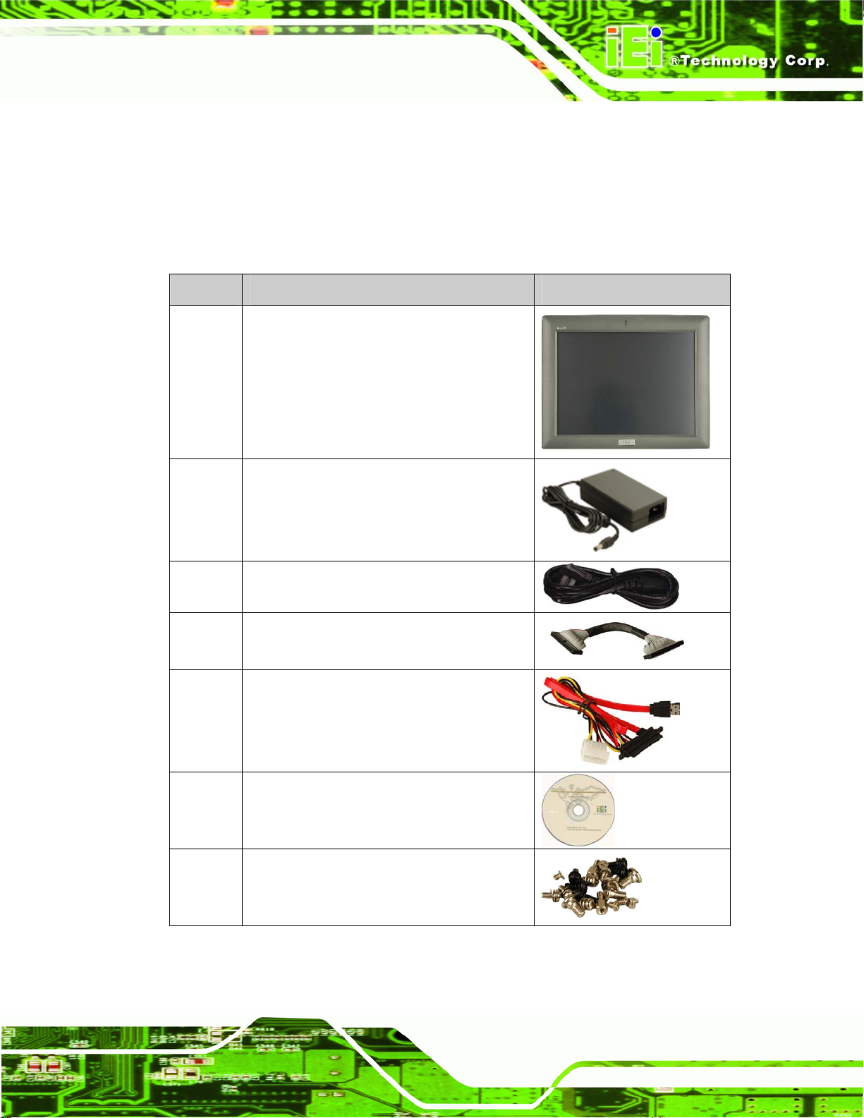
AFL-xxx-CX2 Panel PC
Step 7: Open the small box inside and make sure all the components listed in the
packing list are present. Step 0:
3.4.1 Packing List
The AFL-xxx-CX2 is shipped with the following components:
Quantity Item Image
1 AFL-xxx-CX2
1 48 W power adapter (AFL-07A-CX2 and
AFL-08AH-CX2)
60 W power adapter (AFL-10A-CX2 and
AFL-12B-CX2)
1 Power cord
1
1 eSATA cable
1 User manual CD and driver CD
1 Screw set
HDD cable (only AFL-12B -CX2)
Page 47
Page 66

Quantity Item Image
1 Touch pen
Table 3-1: Packing List
3.4.2 Optional Items
These optional extras are available for the AFL-xxx-CX2
Quantity Item Image
1 Wall mounting kit
AFL-xxx-CX2 Panel PC
4
(6)
1 Stand mounting kit
1 128 MB CompactFlash® card with Windows
1 1.0 GB CompactFlash® card with Windows
Panel mounting kit
(AFL-12B-CX2)
CE 5.0 pre-installed and SDK
XPE pre-installed
Page 48
Table 3-2: Optional Items
If any of these items are missing or damaged, contact the distributor or sales
representative immediately.
Page 67

AFL-xxx-CX2 Panel PC
3.5 CompactFlash® Card Installation
The AFL-xxx-CX2 has one CompactFlash® slot inside the rear panel. To install the
CompactFlash® card, follow the instructions below.
Step 1: Remove the retention screws (
Figure 3-4) and lift the plastic cover off the flat panel PC.
Figure 3-1: AFL-07A-CX2 Cover Retention Screws
Figure 3-1, Figure 3-2, Figure 3-3 and
Figure 3-2: AFL-08AH-CX2 Cover Retention Screws
Figure 3-3: AFL-10A-CX2 Cover Retention Screws
Page 49
Page 68
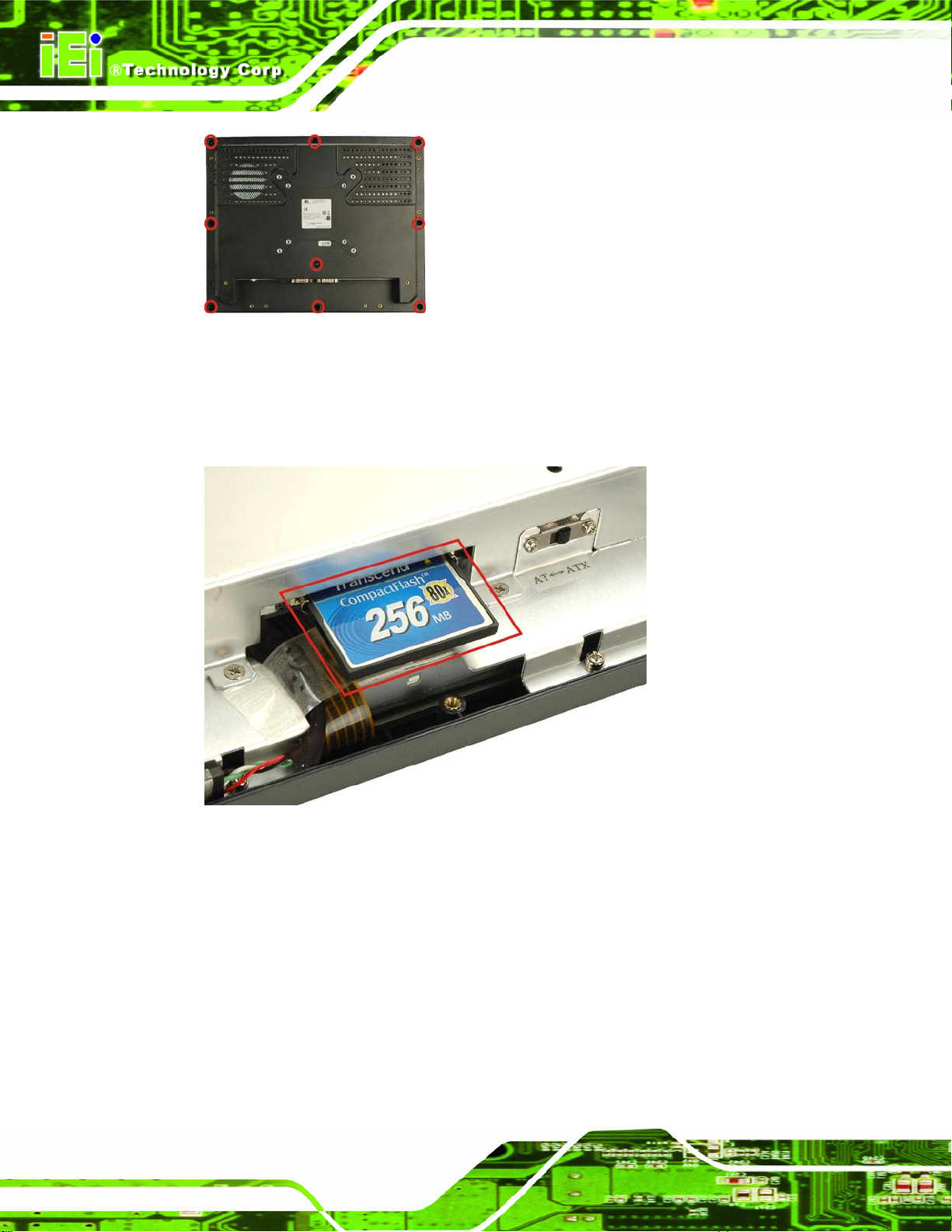
Figure 3-4: AFL-12B-CX2 Back Cover Retention Screws
Step 2: Locate the CompactFlash® card slot. Insert a CompactFlash® card into the slot
Figure 3-5).
(
AFL-xxx-CX2 Panel PC
Figure 3-5: CompactFlash® Card Slot Location
Step 3: Replace the plastic back cover. Once replaced, fasten the previously removed
retention screws. Step 0:
3.6 Hard Drive Installation
The AFL-12B-CX2 has space for a hard drive. To install the hard drive, please follow the
steps below:
Page 50
Page 69

AFL-xxx-CX2 Panel PC
Step 1: Remove the plastic back cover. See Section 3.5 above.
Step 2: Remove the retention screws securing the internal aluminum cover (
and lift the aluminum cover off the panel PC.
Figure 3-6: AFL-12B-CX2 Cover Retention Screws
Figure 3-6)
Step 3: Remove the four hard drive bracket retention screws (
hard drive bracket off the panel PC.
Figure 3-7) and lift the
Page 51
Page 70

Figure 3-7: AFL-12B-CX2 Bracket Retention Screws
AFL-xxx-CX2 Panel PC
Step 4: Attach the hard d rive bracket to the hard drive. To do this, align the four retention
screw holes in the both sides of the hard drive bracket with the retention screw
holes on the sides of the hard drive. Insert four retention screws into the hard
drive bracket (
Figure 3-8).
Page 52
Figure 3-8: AFL-xxx-CX2 Hard Drive Retention Screws
Step 5: Connect the SATA/IDE cable to the rear of hard drive.
Page 71

AFL-xxx-CX2 Panel PC
Step 6: Install the hard drive into the p anel PC by aligning the retention screw holes in
the hard drive brackets with the retention screw holes o n the chassis. Insert the
four retention screws.
Step 7: Replace the aluminum back cover to the chassis.
Step 8: Replace the plastic back cover. Step 0:
3.7 AT/ATX Mode Selection
AT and ATX power modes can both be used on the AFL-xxx-CX2. The selection is made
through an AT/ATX switch on the aluminum chassis inside the plastic back cover
(
Figure 3-9). To select AT mode or ATX mode, follow the steps below.
Step 1: Remove the plastic back cover. See Section
Step 2: Locate the AT/ATX switch on the aluminum chassis (
3.5 above.
Figure 3-9).
Figure 3-9: AT/ATX Switch Location
Step 3: Adjust the AT/ATX switch. Step 0:
Page 53
Page 72

3.7.1 AT Power Mode
With the AT mode selected, the power is controlled by a central power unit rather than a
power switch. The AFL-xxx-CX2 turns on automatically when the power is connected. The
AT mode benefits a production line to control multiple panel PCs from a central
management center and other applications including:
ATM
Self-service kiosk
Plant environment monitoring system
Factory automation platform
Manufacturing shop flow
3.7.2 ATX Power Mode
With the ATX mode selected, the AFL-xxx-CX2 goes in a standby mode when it is turned
AFL-xxx-CX2 Panel PC
off. The panel PC can be easily turned on via network or a power switch in standby mode.
Remote power control is perfect for advertising applications since the broadcasting time
for each panel PC can be set individually and controlled remotely. Other possible
application includes
Security surveillance
Point-of-Sale (POS)
Advertising terminal
3.8 Mounting the System
WARNING!
When mounting the flat panel PC onto an arm, onto the wall or onto a
panel, it is better to have more than one person to help with the
installation to make sure the panel PC does not fall down and get
damaged.
Page 54
The four methods of mounting the AFL-xxx-CX2 are listed below.
Page 73

AFL-xxx-CX2 Panel PC
Wall mounting
Stand/Arm mounting
The four mounting methods are described below.
3.8.1 Wall Mounting
To mount the flat panel PC onto the wall, please follow the steps below.
Step 1: Select the location on the wall for the wall-mounting bracket.
Step 2: Carefully mark the locations of the four brackets scre w holes on the wall.
Step 3: Drill four pilot holes at the marked locations on the wall for the bracket retention
screws.
Step 4: Align the wall-mounting bracket screw holes with the pilot holes.
Step 5: Secure the mounting-bracket to the wall by inserting the retentio n screws into
the four pilot holes and tightening them (
Figure 3-10: Wall-mounting Bracket
Figure 3-10).
Page 55
Page 74

Step 6: Insert the four monitor mounting screws provided in the wall mounting kit into the
four screw holes on the real panel of the flat panel PC and tighten until the screw
AFL-xxx-CX2 Panel PC
shank is secured against the rear panel (
Step 7: Align the mounting screws on the monitor rear panel with the mounting holes on
the bracket.
Step 8: Carefully insert the screws through the holes and gently pull the monitor
downwards until the monitor rests securely in the slotted holes (
Ensure that all four of the mounting screws fit snuggly into their respective
slotted holes.
Figure 3-11).
Figure 3-11).
Page 56
Figure 3-11: Chassis Support Screws
Page 75

AFL-xxx-CX2 Panel PC
NOTE:
In the diagram below the bracket is already installed on the wall.
Step 9: Secure the panel PC by fastening the retention screw of the wall-mounting
bracket. (
Figure 3-12).Step 0:
Figure 3-12: Secure the Panel PC
3.8.2 Arm Mounting
The AFL-xxx-CX2 is VESA (Video Electronics Standards Association) compliant and can
be mounted on an arm with a VESA compliant interface pad. To mount the AFL-xxx-CX2
series on an arm, please follow the steps below.
Page 57
Page 76

Step 1: The arm is a separately purchased item. Please correctly mount the arm onto
the surface it uses as a base. To do this, refer to the installation documentation
that came with the mounting arm.
AFL-xxx-CX2 Panel PC
NOTE:
When purchasing the arm please ensure that it is VESA compliant and
that the arm has the correct interface pad. If the mounting arm is not
VESA compliant it cannot be used to support the AFL-xxx-CX2.
Step 2: Once the mounting arm has been firmly att ached to the surfa ce, lif t the flat panel
PC onto the interface pad of the mounting arm.
Step 3: Align the retention screw holes on the mounting arm interface with those in the
flat panel PC. The AFL-xxx-CX2 arm mount retention screw holes are shown in
Figure 3-13 and Figure 3-14.
Figure 3-13: Arm Mounting Screw Holes (AFL-07A-CX2 and AFL-08AH-CX2)
Page 58
Page 77
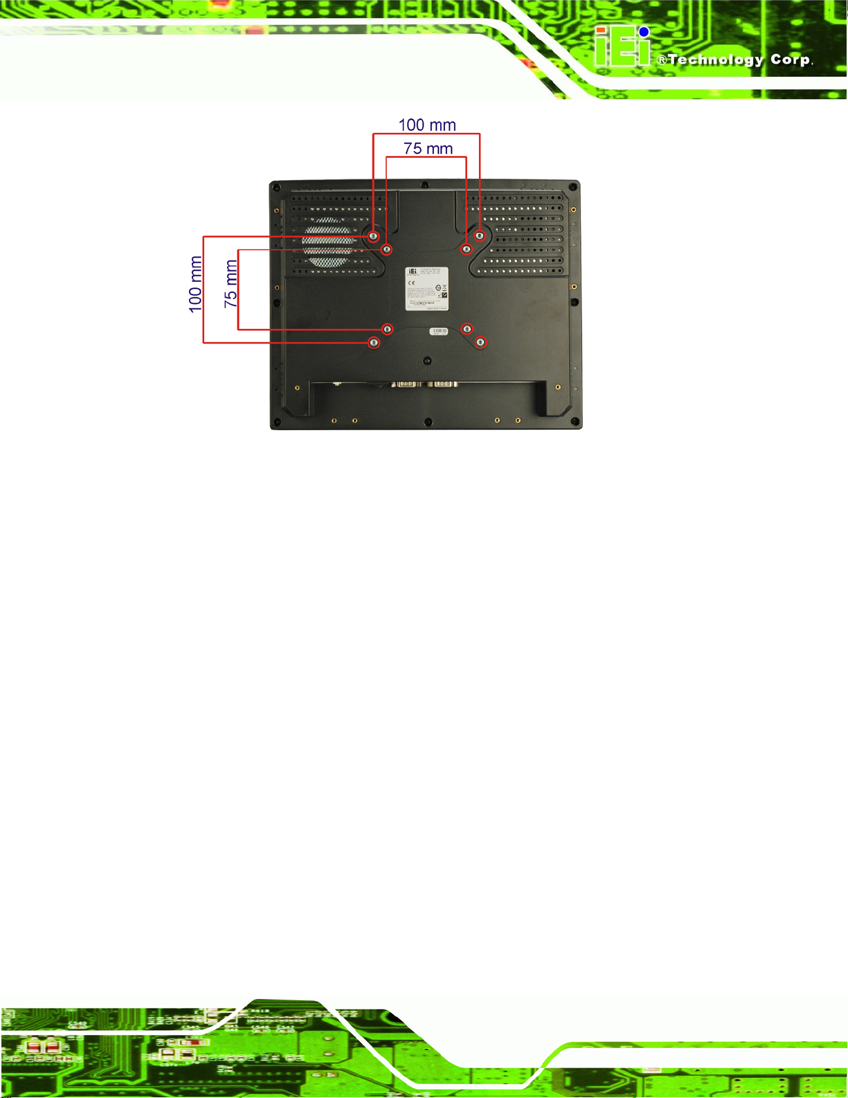
AFL-xxx-CX2 Panel PC
Figure 3-14: Arm Mounting Screw Holes (AFL-10A-CX2 and AFL-12B-CX2)
Step 4: Secure the flat panel PC to the interface pad by inserting four retention screws
through the bottom of the mounting arm interface pad and into the flat panel
PC.Step 0:
3.8.3 Panel Mounting
To mount the AFL-xxx-CX2 into a panel, please follow the steps below.
Step 1: Select the position on the panel to mou nt the flat panel PC.
Step 2: Cut out a section from the panel that corresponds to the rea r panel dimensions
of the flat panel PC. Take care that the panel section that is cut out is smaller
than the overall size of the metal frame that surrounds the flat panel PC but just
large enough for the rear panel of the flat panel PC to fit through (
Figure 3-18).
and
Figure 3-17
Page 59
Page 78
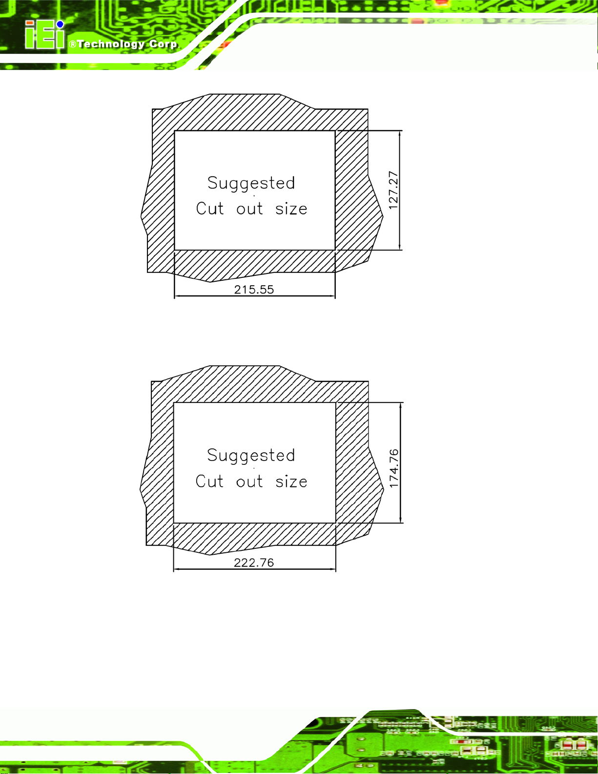
Figure 3-15: AFL-07A-CX2 Panel Opening
AFL-xxx-CX2 Panel PC
Figure 3-16: AFL-08AH-CX2 Panel Opening
Page 60
Page 79
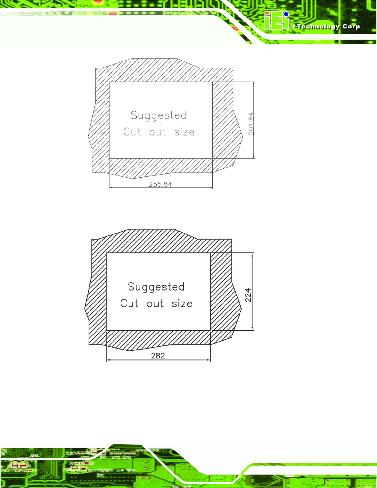
AFL-xxx-CX2 Panel PC
Figure 3-17: AFL-10A-CX2 Panel Opening
Figure 3-18: AFL-12B-CX2 Panel Opening
Step 3: Slide the flat panel PC through the hole until the aluminum frame is flush ag ainst
the panel.
Page 61
Page 80

Step 4: Insert the panel mounting clamps into the pre-formed holes along the edges of
the chassis, behind the aluminum frame. There are a total of 6 panel mounting
clamps for AFL-xxx-CX2.
Step 5: T ighten the screws that p a ss through the p anel moun ting clamp s until the plastic
AFL-xxx-CX2 Panel PC
caps at the front of all the screws are firmly secured to the panel (
Step 0:
Figure 3-19).
Figure 3-19: Tighten the Panel Mounting Clamp Screws
3.8.4 Cabinet and Rack Installation
The AFL-xxx-CX2 can be installed into a cabinet or rack. The installation procedures are
similar to the panel mounting installation. To do this, please follow the steps below:
Page 62
Page 81

AFL-xxx-CX2 Panel PC
NOTE:
When purchasing the cabinet/rack installation bracket, make sure it is
compatible with both the AFL-xxx-CX2 flat panel PC and the
rack/cabinet into which the AFL-xxx-CX2 is installed.
Step 1: Slide the rear chassis of the AFL-xxx-CX2 through the rack/cabinet bracket until
the aluminum frame is flush against the front of the bracket (
Figure 3-20: The Rack/Cabinet Bracket
Step 2: Insert the rack mounting clamp s into the pre-formed holes along the edges of
the flat panel PC, behind the ABS/PC plastic frame. There are a total of 6 rack
mounting clamps for the AFL-xxx-CX2.
Figure 3-20).
Step 3: Tighten the screws that pass through the rack mounting clamps until the plastic
caps at the front of all the screws are firmly secured to the bracket
Figure 3-21).
(
Page 63
Page 82

Figure 3-21: Secure the Rack/Cabinet Bracket
AFL-xxx-CX2 Panel PC
Step 4: Slide the flat panel PC with the att ach ed rack/cabinet bracket into a rack or
cabinet (
Figure 3-22: Install into a Rack/Cabinet
Figure 3-22).
Page 64
Page 83

AFL-xxx-CX2 Panel PC
Step 5: Once the flat panel PC with the attached rack/cabin et bracket has been p roperly
inserted into the rack or cabinet, secure the front of the rack/cabinet bracket to
the front of the rack or cabinet (
3.9 Bottom Panel Connectors
3.9.1 LAN Connection
There are two external RJ-45 LAN connectors. The RJ-45 connectors enable connection
to an external network. To connect a LAN cable with an RJ-45 connector, please follow
the instructions below.
Step 1: Locate the RJ-45 connectors on the bottom panel of the AFL-xxx-CX2 Series.
Step 2: Align the connectors. Align the RJ-45 conne ctor on the LAN cable with one of
the RJ-45 connectors on the bottom panel of the AFL-xxx-CX2. See
Figure 3-23.
Figure 3-22).Step 0:
Figure 3-23: LAN Connection
Step 3: Insert the LAN cable RJ-45 connector. Once aligned, gently insert the LAN
cable RJ-45 connector into the onboard RJ-45 connector. Step 0:
Page 65
Page 84

3.9.2 Serial Device Connection
The AFL-xxx-CX2 has two single female DB-9 connectors on the bottom panel for a serial
device. Follow the steps below to connect a serial device to the AFL-xxx-CX2 Series panel
PC.
Step 1: Locate the DB-9 connector. The location of the DB-9 connector is shown in
Chapter 2.
Step 2: Insert the serial connector. Insert the DB-9 connector of a serial device into
AFL-xxx-CX2 Panel PC
the DB-9 connector on the bottom panel. See
Figure 3-24.
Page 66
Figure 3-24: Serial Device Connector
Step 3: Secure the connector. Secure the serial device connector to the e xternal
interface by tightening the two retention screws on either side of the connector.
Step 0:
Page 85

AFL-xxx-CX2 Panel PC
3.9.3 USB Device Connection
There are four external USB 2.0 connectors. All connectors are perpendicular to the
AFL-xxx-CX2. To connect a USB 2.0 or USB 1.1 device, please follow the instructions
below.
Step 1: Located the USB connectors. The locations of the USB connectors are shown
in Chapter 2.
Step 2: Align the connectors. Align the USB device connect or with on e of the
connectors on the bottom panel. See
Figure 3-25.
Figure 3-25: USB Device Connection
Step 3: Insert the device connector. Once aligned, gently insert the USB device
connector into the onboard connector. Step 0:
Page 67
Page 86

AFL-xxx-CX2 Panel PC
Chapter
4
4 System Maintenance
Page 68
Page 87

AFL-xxx-CX2 Panel PC
4.1 System Maintenance Introduction
If the components of the AFL-xxx-CX2 fail they must be replaced, such as the wireless
LAN module or the motherboard. Please contact the system reseller or vendor to
purchase the replacement parts. Back cover removal instructions and jumper settings for
the AFL-xxx-CX2 are described below.
4.2 Motherboard Replacement
A user cannot replace a motherboard. If the motherboard fails it must be shipped back to
IEI to be replaced. If the system motherboard has failed, please contact the system vendor ,
reseller or an IEI sales person directly.
4.3 Internal Aluminum Cover Removal
WARNING!
Before removing the back cover, make sure the power if off. Failing to
do so may lead to severe damage of AFL-xxx-CX2 series and injury to
the body.
WARNING!
Please take antistatic precautions when working with the internal
components. The interior of the AFL-xxx-CX2 contains very sensitive
electronic components. These components are easily damaged by
electrostatic discharge (ESD). Before working with the internal
components make sure all the anti-static precautions described earlier
have been observed.
To replace any of the following components,
Motherboard
Page 69
Page 88
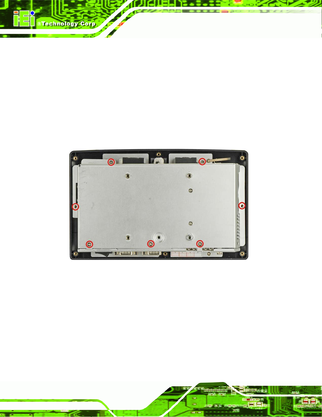
DDR2 memory module
Wireless LAN module
Bluetooth module
HSDPA m odule
Inverter
The internal aluminum back cover of the AFL-xxx-CX2 series must be removed. To
remove the aluminum back cover, please follow the steps below.
AFL-xxx-CX2 Panel PC
Step 1: Remove the retention screws securing the internal aluminum cover (
Figure 4-2, Figure 4-3 and Figure 4-4).
Figure 4-1: AFL-07A-CX2 Aluminum Back Cover Retention Screws
Figure 4-1,
Page 70
Page 89

AFL-xxx-CX2 Panel PC
Figure 4-2: AFL-08AH-CX2 Aluminum Back Cover Retention Screws
Figure 4-3: AFL-10A-CX2 Aluminum Back Cover Retention Screws
Page 71
Page 90
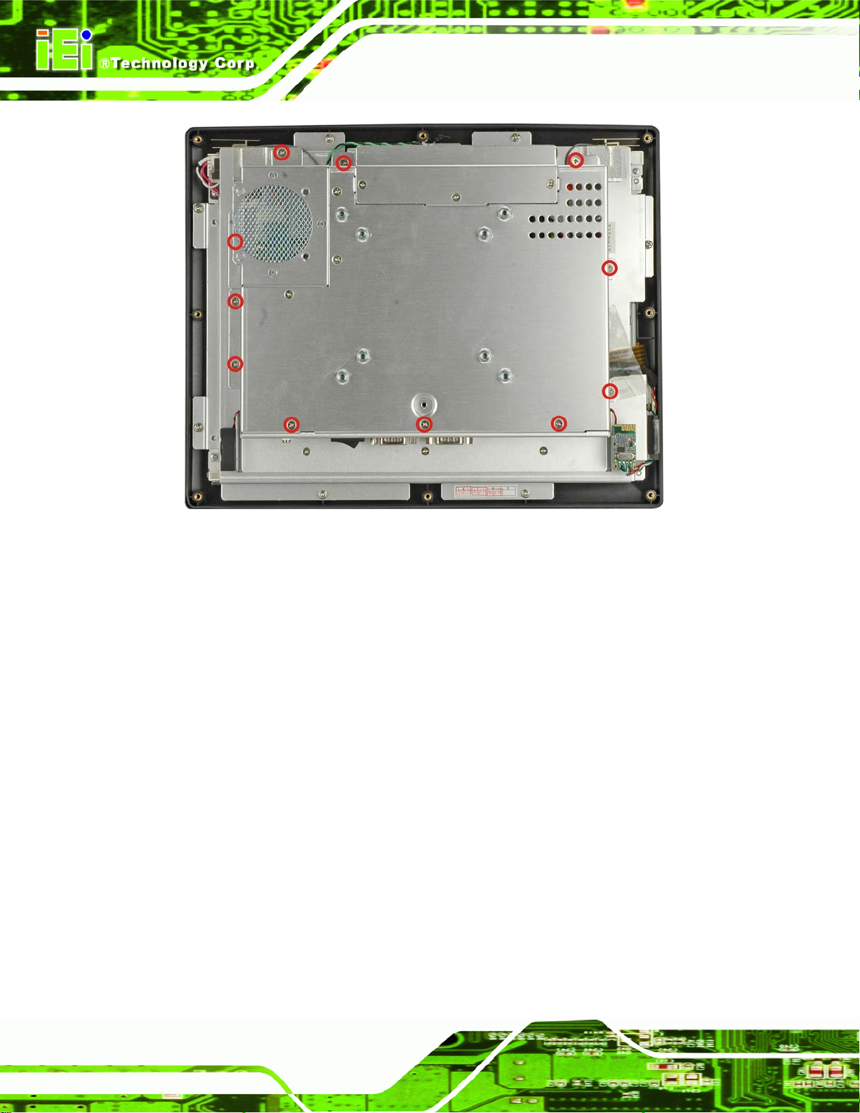
AFL-xxx-CX2 Panel PC
Figure 4-4: AFL-12B-CX2 Aluminum Back Cover Retention Screws
Step 2: Lift the aluminum cover off the AFL-xxx-CX2. The AT/ATX switch on the
aluminum cover is connected to the motherboard. Be careful when lifting the
cover off. Step 0:
4.4 Memory Module Replacement
The flat panel PC is preinstalled with a 512 MB DDR2 memory module. If the memory
module fails, follow the instructions below to replace the memory module.
Step 1: Remove the back cover. See Section
Step 2: Remove the internal aluminum back cover. See Section
Step 3: Locate the DDR2 memory module on the motherboard of the flat panel PC
Figure 4-5).
(
3.5 above.
4.3 above.
Page 72
Page 91

AFL-xxx-CX2 Panel PC
Figure 4-5: Memory Module
Step 4: Remove the thermal pa d off the memory module.
Step 5: Remove the DDR2 memory module by pulling both the spring retainer clips
outward from the socket.
Step 6: Grasp the DDR2 memory module by the edges and carefully pull it out of the
socket.
Step 7: Install the new DDR2 memory module by pushing it into the socket at an angle
Figure 4-6).
(
Step 8: Gently pull the spring retai ner clips of the SO-DIMM socket out and push the
rear of the DDR2 memory module down (
Step 9: Release the spring retainer clips on the SO-DIMM socket. They clip into place
and secure the DDR2 memory module in the socket.
Figure 4-6).
Page 73
Page 92

Figure 4-6: DDR2 SO-DIMM Module Installation
Step 10: Re-attach the thermal pad into the memory module. Step 0:
4.5 Jumper Settings
AFL-xxx-CX2 Panel PC
NOTE:
A jumper is a metal bridge that is
used to close an electrical circuit. It
consists of two metal pins and a small
metal clip (often protected by a plastic
cover) that slides over the pins to
connect them. To CLOSE/SHORT a
jumper means connecting the pins of
the jumper with the plastic clip and to
OPEN a jumper means removing the
plastic clip from a jumper.
The jumpers on the AFLMB-CX2-R10 are listed below.
4.5.1 AT/A TX Power Selection (JP18)...................................................76
4.5.2 Clear CMOS (JP5)........................................................................76
4.5.3 CompactFlash
®
Master/Slave Selection (JP8)..............................76
Jumper
Page 74
4.5.4 COM1 Pin-9 Setting (JP6) ............................................................77
Page 93

AFL-xxx-CX2 Panel PC
4.5.5 COM2 Settings..............................................................................77
4.5.6 LCD Voltage Selection (JP4) ........................................................78
4.5.7 Panel Resolution (JP2) .................................................................79
4.5.8 T ouch Panel Type (J1)..................................................................79
The jumper locations are shown in Figure 4-7.
Figure 4-7: Jumper Locations
Page 75
Page 94
4.5.1 AT/ATX Power Selection (JP18)
This jumper sets the power as using AT power or ATX power.
JP18 Description
1-2 closed ATX po wer
1-2 open AT power
Table 4-1: AT/ATX Power Selection
4.5.2 Clear CMOS (JP5)
The Clear CMOS jumper is for resetting the BIOS. To reset the BIOS, turn off the
computer, move the jumper to the “Clear CMOS setup” position, turn on the computer for
5 seconds, turn off, then set the jumper to the normal position. The BIOS is then returned
to default settings.
AFL-xxx-CX2 Panel PC
JP5 DESCRIPTION
1-2 Normal operation
2-3 Clear CMOS setup
Table 4-2: Clear CMOS
4.5.3 CompactFlash® Master/Slave Selection (JP8)
This jumper sets the CompactFlash® disk as the IDE master or the IDE slave. The
CompactFlash® master/slave jumper is a part of jumper JP8, only the pins relating to this
setting are covered.
JP8 Description
9-10 Open Master
9-10 Closed Slave
Table 4-3: CompactFlash® Master/Slave Selection
Page 76
Page 95
AFL-xxx-CX2 Panel PC
4.5.4 COM1 Pin-9 Setting (JP6)
Pin 9 on serial port COM1 can be set to provide 5 V or 12 V of power, or as the ring
indicator.
JP6 Description
1-3 12 V
3-5 5 V
7-9 RI
Table 4-4: COM1 Pin-9 Setting
4.5.5 COM2 Settings
The following jumpers are used to set up the COM2 serial port.
4.5.5.1 COM2 Pin-9 Setting (JP6)
Pin 9 on serial port COM2 can be set to provide 5 V or 12 V of power, or as the ring
indicator.
JP6 Description
2-4 12 V
4-6 5 V
8-10 RI
Table 4-5: COM2 Pin-9 Setting
4.5.5.2 COM2 Mode Select (JP7)
The COM2 can be selected as RS-232, RS-422 or RS-485.
JP7 Description
1-2, 3-4 RS-232
1-2, 5-6 RS-422
7-8 RS-485
Table 4-6: COM2 Mode Select
Page 77
Page 96
4.5.5.3 COM2 RS-422/485 Select (JP15)
This jumper sets COM2 as either RS-422 or RS-485. This jumper should be set in
conjunction with the other COM2 jumpers.
JP15 Description
1-2, 3-4 RS-422
3-4, 5-6 RS-485
Table 4-7: COM2 Mode Select
4.5.5.4 Pin-12 Signal Setting (JP8)
The Pin-12 signal setting sets the signal type used on pin 12.
JP8 Description
AFL-xxx-CX2 Panel PC
1-2, 4-5, 7-8, 10-11 RS-232
2-3, 5-6, 8-9, 11-12 RS-422/485
Table 4-8: COM2 Mode Select Jumper Settings
4.5.6 LCD Voltage Selection (JP4)
WARNING!
Do not change this voltage. This voltage has been preset and is
compatible with the currently installed LCD screen. Changing this
jumper setting may cause damage to the system.
The LCD Voltage Setup jumper sets the voltage for the LCD screen. This setting MUST
NOT be changed.
Page 78
Page 97

AFL-xxx-CX2 Panel PC
JP4 DESCRIPTION
1-2 +3.3 V
2-3 +5 V
Table 4-9: LCD Voltage Setup Jumper Settings
4.5.7 Panel Resolution (JP2)
This jumper selects the video resolution. This pin header is shared with the GPIO
connector. Only the settings relevant to panel resolution selection are shown here.
JP2 Description
5-6, 7-8, 9-10 640 x 480, 18-bit
7-8, 9-10 800 x 600, 18-bit
5-6, 9-10 1024 x 768, 18-bit
9-10 1280 x 1024, 36-bit
5-6, 7-8 800 x 480, 18-bit
7-8 1024 x 768, 24-bit
5-6 1280 x 1024, 48-bit
Open 1280 x 800, 18-bit
Table 4-10: COM2 Mode Select Jumper Settings
4.5.8 Touch Panel Type (J1)
The touch panel type selects whether the connected touch panel is a 4-wire or 5-wire
touch panel.
J1 DESCRIPTION
1-2 5-wire
3-4 4-wire
Table 4-11: Touch Panel Type
Page 79
Page 98

AFL-xxx-CX2 Panel PC
Chapter
5
5 BIOS Setup
Page 80
Page 99
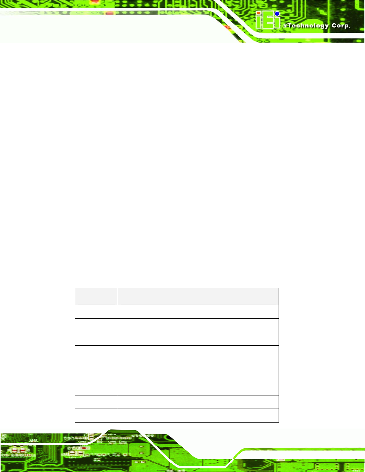
AFL-xxx-CX2 Panel PC
5.1 Introduction
A licensed copy of AMI BIOS is preprogrammed into the ROM BIOS. The BIOS setup
program allows users to modify the basic system configuration. This chapter describes
how to access the BIOS setup program and the configuration options that may be
changed.
5.1.1 Starting Setup
The AMI BIOS is activated when the computer is turned on. The setup program can be
activated in one of two ways.
1. Press the D
2. Press the D
message appears on the screen. 0.
If the message disappears before the D
again.
ELETE key as soon as the system is turned on or
ELETE key when the “Press Del to enter SETUP”
ELETE key is pressed, restart the computer and try
5.1.2 Using Setup
Use the arrow keys to highlight items, press ENTER to select, use the PageUp and
PageDown keys to change entries, press F1 for help and press E
keys are shown in.
Key Function
Up arrow Move to previous item
Down arrow Move to next item
Left arrow Move to the item on the left hand side
SC to quit. Navigation
Right arrow Move to the item on the right hand side
Esc key Main Menu – Quit and not save changes into CMOS
Status Page Setup Menu and Option Page Setup Menu --
Exit current page and return to Main Menu
Page Up key Increase the numeric value or make changes
Page Dn key Decrease the numeric value or make changes
Page 81
Page 100

Key Function
F1 key General help, only for St atus Page Setup Menu and Option
F2 /F3 key Change color from total 16 colors. F2 to select color
F10 key Save all the CMOS changes, only for Main Menu
Table 5-1: BIOS Navigation Keys
5.1.3 Getting Help
When F1 is pressed a small help window describing the appropriate keys to use and the
AFL-xxx-CX2 Panel PC
Page Setup Menu
forward.
possible selections for the highlighted item appears. To exit the Help Window press E
the F1 key again.
5.1.4 Unable to Reboot After Configuration Changes
If the computer cannot boot after changes to the system configuration is made, CMOS
defaults. Use the jumper described in Chapter 4, Section
4.5.
5.1.5 BIOS Menu Bar
The menu bar on top of the BIOS screen has the following main items:
Main Changes the basic system configuration.
Advanced Changes the advanced system settings.
PCIPnP Changes the advanced PCI/PnP Settings
Boot Changes the system boot configuration.
Security Sets User and Supervisor Passwords.
Chipset Changes the chipset settings.
SC or
Page 82
Exit Selects exit options and loads default settings
The following sections completely describe the configuration options found in the menu
items at the top of the BIOS screen and listed above.
 Loading...