

Page 1

232iLM Keypad Installation and Programming Instructions
Note: This product is designed to be installed and serviced b y security and lock industry professionals.
Specifications
Case Dimensions:
1
6
/2”L x 13/4”W x 11/8”D
Electrical:
Voltage: 5-12VDC (reader)
12-24VAC/DC (controller)
Current (max): 120mA
Relay Contacts:
Main Relay (controller): 2A
Aux Relays (controller): 1A
Bell Relay:
Form A; 1 Amp @ 30VDC;
500mA @ 125VAC
Environmental:
-20 º F to 130° F
Description:
Features
● Vandal Resist ant Case
● Sealed for Indoor or Outdoor Applications
● LED's for Relay Status Indication
● Bell Output
● Surface Mount
● Illuminated Hardened Keys
● Rated for Greater than One Million Key Cycles
Applications
● Low to Medium/Heavy Traffic Areas
● Rough Service Environments
● Mullion Frame Mounting
● Dimly Lit Areas
Wire Harness Configuration:
The 232iLM Access Control unit consists of two pieces: an
SSWiLM keypad front end and a 232 Access Control
Module. IEI's Door-Gard Series SSWiLM keypad combines
elegant looks with a mullion mount design in a rugged,
vandal resistant case, which you can use for almost any
application. The SSWiLM has hardened backlit keys
designed to perform in medium to high traffic areas and in
rough duty environments. The electronics are also
conformal coated, which makes the keypad suitable for
indoor or outdoor applications.
Basic Operation:
To gain access through the door enter your code (1-6 digits)
followed by the * key on the keypad.
Packing List:
(1) SSWiLM Keypad
(1) IEI 232 Controller
(1) Eight-Conductor Wire Harness
(4) Three-Conductor Wire Harness
(1) Controller Hardware Pack
(1) Mullion Hardware Pack
5
(1)
/64” Allen Wrench
(1) Anti-Oxidant Grease Pack
(1) Installation/Programming Manual
(1) Self-Contained Access Control Programming Guide
Pin Wire Color Signal Name
1 Red Power (+)
2 Black Power (-)
3 White/Black Data 0
4 White/Yellow Data 1
5 Blue Not Used
6 Brown Not Used
7 White Bell Relay Contact (A)
8 White Bell Relay Contact (B)
Wiring Requirements:
18 AWG – 1000 Ft.
20 AWG – 500 Ft.
22 AWG – 250 Ft.
Document # 6050800 Rev 1.1 1 of 12 www.ieib.com
Page 2

Keypad Installation Procedure:
Step 1: Drill through the back plate using a 11/64” bit. Use the template on the back page to accurately mark the mounting
holes before drilling. Then drill the mounting holes with a
9
/64” drill bit. Also drill the hole for the wires. This may
vary depending on the number of co nductors required.
Step 2: On the keypad end, strip back the insulator from the wire and tape the drain wire (shield) to the jacket. Now
connect the required wires to the 8-conductor wire harness provided. The wire harness plugs into the 8-position
connector on the keypad. At the other end of your wire run, strip back the insulator from the wire but do not
the drain wire to the jacket. The drain wire must
be connected to ground at the controller end. See the diagrams
tape
below.
Step 3: Finally mount the SSWiLM keypad onto the mounting surface using the provided screws. Do no over-tighten the
screws, which may result in damage.
Wiring the SSWiLM to an IEI 232 Access Control Module
The connection between the SSWiLM and the 232 Controller requires a 4-conductor, stranded wire with overall foil shield.
The 8-conductor wire harness from the keypad connects to connector P6 on the controller. Connect the wires, color to
color (red to red, black to black, white/black to white/black and white/yellow to white/yellow). Refer to the wire lengths on
the first page. As mentioned above, the drain wire must be attached to Ground on the controller si de, which is the Vterminal or negative of your power supply.
Document # 6050800 Rev 1.1 2 of 12 www.ieib.com
Page 3

Basic Access Control Using an Electromagnetic Lock (Maglock)
IEI recommends a
filtered and regulated
DC power supply.
If you aren't using door
contacts you must short
the white/orange and
white wires
Basic Access Control Using an Electric Door Strike
IEI recommends a
filtered and regulated
DC power supply.
If you aren't using door
contacts you must short
the white/orange and
white wires
Document # 6050800 Rev 1.1 3 of 12 www.ieib.com
Page 4

Integrated Access Control Wiring
IEI recommends a
filtered and regulated
DC power supply.
Wire Color Relay Connection
Gray Normally Closed
Blue Common
Green Normally Open
Document # 6050800 Rev 1.1 4 of 12 www.ieib.com
Page 5

Wiring the Bell Output to a Speaker:
The SSWiLM keypad has a built in bell button, which triggers a relay output when pressed. This relay is normally open
and the contact closes when triggered. You can use this relay output to trigger devices that require a momentary closure,
such as a doorbell. The relay output provides a dry contact, b ut you can run up to 24 VDC or 125 VAC through it for
devices that require power to operate. The diagram below shows these connections.
Keypad Mounting Height
Mounting height can vary depending on requirements. An appropriate range is typically between 48 and 52 inches on
center off the flo or.
Document # 6050800 Rev 1.1 5 of 12 www.ieib.com
Page 6
Programming the SSWiLM Keypad
The SSWiLM keypad has it's own local programming options. All user code s and other access control features are
programmed into the controller. Refer the Self-Contained Access Control Programming Guide for those features. The
programming options chart below shows all the programming commands available in the SSWiLM.
To program the SSWiLM you first must enter program mode. To enter program mode enter the following on the keypad:
099 # program code * (default program code is 6789).
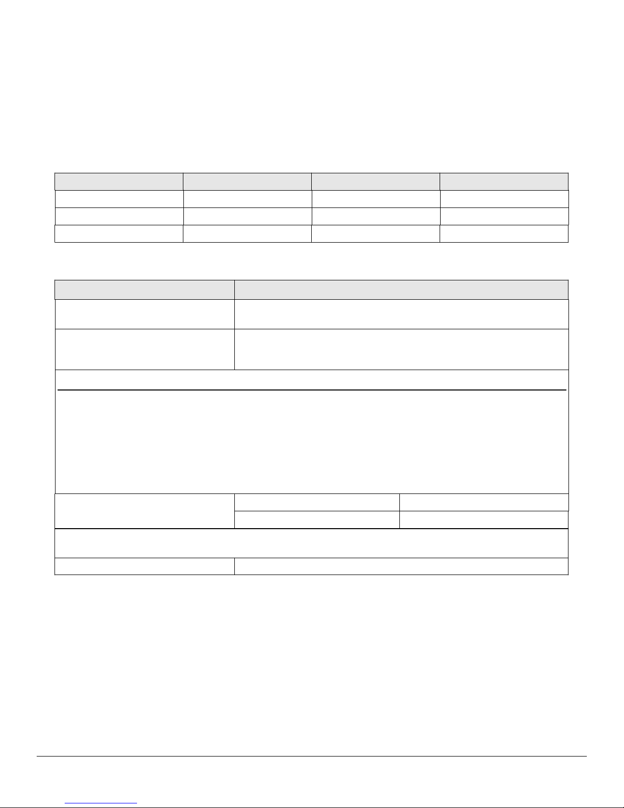
Keypad Default Settings
Option Default Setting Option Default Setting
Local Program Code 6789 Audio Keypress Feedback Enabled
Visual Keypress Feedback Enabled Door Bell Select Continuous
Keypad Illumination Enabled Keypad Dimming Enabled
Programming Options Chart
Command/Action Keys to Enter/Details
Command 90
Change Local Program Code
Command 91
Set/Clear Keypad Options (options
below, defaults in bold)
Option Clear Set
0 – Visual Keypress Feedback 0 = Disabled 1 = Enabled
1 – Audio Keypress Feedback 0 = Disabled 1 = Enabled
11 – Keypad Illumination 0 = Disabled 1 = Enabled
12 – Keypad Dimming 0 = Disabled (always bright) 1 = Enabled
13 – Door Bell Select 0 = Disabled 1 = Enabled
Command 92
Set Door Bell Duration
Command 96
Reset Keypad to Default Settings
Exit Program Mode Press the * Key
90 # 0 # 0 # new code * new code * (default = 6789)
91 # option # set/clear # **
92 # 4 # time # ** Set timed output (1 – 99 seconds)
92 # 4 # 0 # ** Set to continuous
96 # 0 # 0 # **
Testing the Keypad
After installing the keypad, IEI recommends that you perform the keypad self-test once a year, to ensure that the keypad
is working properly.
● To perform the self-test, with the unit powered up, press the following keys on the keypad: 7890#123456*
● If all 12 keypresses are accepted, the keypad enters self-test mode.
● The LEDs alternate three times followed by the sounder beeping three times.
● When finished the yellow LED starts flickering rapidly.
● Press * to clear.
Document # 6050800 Rev 1.1 6 of 12 www.ieib.com
Page 7

LED Indications
LED State Description
Red Solid Door Locked
Green Solid Door Unlocked
Yellow Solid Programming Error
Yellow Flashing Slowly (single flash) Controller Program Mode
Yellow Flashing Slowly (double flash) Front End Program Mode
Yellow Momentary Flash Visual Keypress Feedback
Replacing the 232m (discontinued) with an 232iLM
The 232iLM is functionally equivalent to the 232m keypad, which was discontinued. It 's not, however, a direct physical
replacement. They are both two piece units, but they use a different control boards. It is not possible to replace just the
mullion keypad portion of the unit. You must replace the entire unit. Refer to the previous sections for wiring your new
232iLM unit.
Program Mode Loopback
If you've forgotten the local program code use the following loopback connection to enter program mode. Power down the
unit, short the wires in the configuration illustrated, then power the unit back up. The yellow LED should be flashing.
Now change your local program code or reset the unit. Power the keypad down and reconnected the wire harness in the
original configuration.
Document # 6050800 Rev 1.1 7 of 12 www.ieib.com
Page 8

Warranty
International Electronics Inc. (IEI) warrants its products to be free from defects in material and workmanship when they
have been installed in accordance with the manufacturer's instructions and have not been modified or tampered with. IEI
does not assume any responsibility for damage or injury to person or property due to improper care, storage, handling,
abuse, misuse, normal wear and tear, or an act of God.
IEI's sole responsibility is limited to the repair (at IEI's option) or the replacement of the defective product or part when
sent to IEI's facility (freight and insurance charges prepaid) after obtaining IEI's Return Material Authorization. IEI will
not be liable to the purchaser or any one else for incidental or cons equential damages arising from any defect in, or
malfunctio n of, its products.
Except as stated above, IEI makes no warranties, either expressed or implied, as to any matter whatsoever, including,
and without limitation to, the condition of its products, their merchantability, or fitness for any particular purpose.
International Electronics Inc.
427 Turnpike St.
Canton, MA 02021
Phone: 1-800-343-9502
Fax: 781-821-4443
Website: www.ieib.com
Document # 6050800 Rev 1.1 8 of 12 www.ieib.com
Page 9

PAGE LEFT BLANK INTENTIONALLY
Document # 6050800 Rev 1.1 9 of 12 www.ieib.com
Page 10

PAGE LEFT BLANK INTENTIONALLY
Document # 6050800 Rev 1.1 10 of 12 www.ieib.com
Page 11

PAGE LEFT BLANK INTENTIONALLY
Document # 6050800 Rev 1.1 11 of 12 www.ieib.com
Page 12
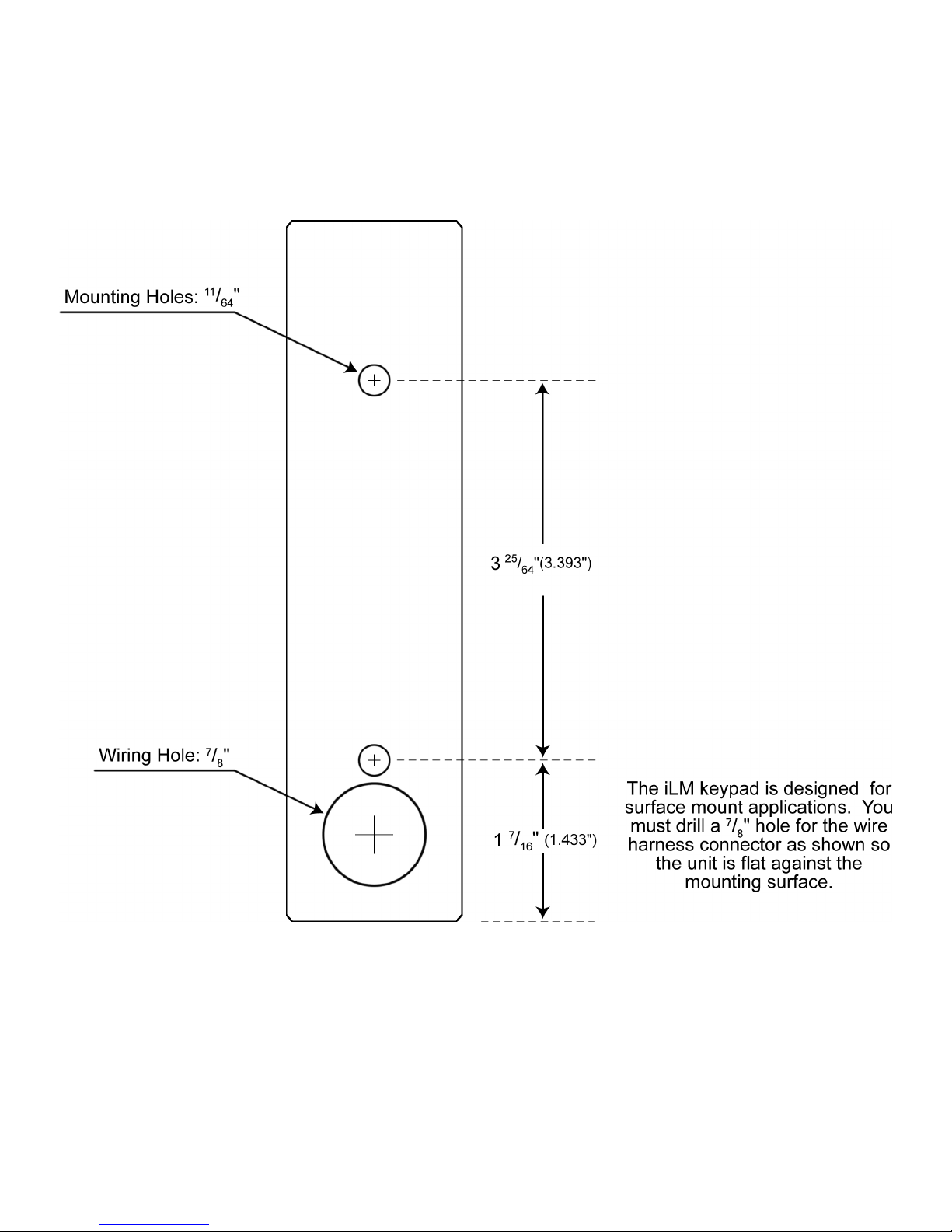
iLM Mounting Template
Document # 6050800 Rev 1.1 12 of 12 www.ieib.com
 Loading...