

Page 1

UPC-V315-NM70 Panel PC
Page i
MODEL:
Panel PC with Touch Screen and Intel® Celeron® Proces sor
Rev. 1.00 – 3 May, 2013
UPC-V315-NM70 Panel PC
IEI Technology Corp.
UPC-V315-NM70
847, GbE, Wireles s, RFID, Bluetooth, USB, Audio,
RS-232/422/485, Ro HS Compliant, IP 65 Protection
User Manual
Page 2
UPC-V315-NM70 Panel PC
Page ii
Date Version Changes
3 May, 2013 1.00 Initial release
Revision
Page 3

UPC-V315-NM70 Panel PC
Page iii
Copyright
COP YRIGHT NOTICE
The information in this document is subject to change without prior notice in order to
improve reliabilit y, design a nd functi on and d oes not r epresent a comm itment on the part
of the manufacturer.
In no event will the manufacturer be liable for direct, indirect, special, incidental, or
consequential damages arising out of the use or inability to use the product or
documentation, even if advised of the possibility of such damages.
This document contains proprietary information protected by copyright. All rights are
reserved. No part of this manual may be reproduced by any mechanical, e lectronic, or
other means in any form without prior written permission of the manufacturer.
TRADEMARKS
All registered tradem ark s and produc t nam es ment ioned here in are us ed for identif icatio n
purposes only and m ay be trademarks and/or registe red trademarks of their respec tive
owners.
Page 4

UPC-V315-NM70 Panel PC
Page iv
Table of Contents
1 INTRODUCTION .......................................................................................................... 1
1.1 OVERVIEW .................................................................................................................. 2
1.2 MODEL VARIATIONS ................................................................................................... 3
1.3 FEATURES ................................................................................................................... 3
1.4 EXTERNAL OVERVIEW ................................................................................................ 3
1.4.1 Front Panel ........................................................................................................ 3
1.4.1.1 LED Indicators ............................................................................................ 5
1.4.2 Bottom Panel ...................................................................................................... 6
1.4.3 Side Panels ......................................................................................................... 8
1.4.4 Rear Panel ......................................................................................................... 8
1.4.5 Frame (Function Keys) ...................................................................................... 9
1.5 DIMENSIONS ............................................................................................................. 10
1.6 SPECIFICATIONS ........................................................................................................ 11
2 UNPACKING ............................................................................................................... 14
2.1 UNPACKING .............................................................................................................. 15
2.2 PACKING LIST ........................................................................................................... 16
3 INSTALLATION ......................................................................................................... 18
3.1 ANTI-STATIC PRECAUTIONS ...................................................................................... 19
3.2 INSTALLATION PRECAUTIONS ................................................................................... 19
3.3 PREINSTALLED COMPONENTS ................................................................................... 20
3.4 SSD INSTALLATION .................................................................................................. 20
3.5 INTERNAL USB DEVICES INSTALLATION .................................................................. 22
3.6 MOUNTING THE SYSTEM .......................................................................................... 24
3.6.1 Arm Mounting .................................................................................................. 25
3.6.2 Stand Mounting ................................................................................................ 26
3.6.3 Wall Mounting .................................................................................................. 27
3.7 BOTTOM PANEL CONNECTORS .................................................................................. 29
3.7.1 External Peripheral Device Connection .......................................................... 29
3.7.2 ACC Mode Selection ........................................................................................ 31
Page 5

UPC-V315-NM70 Panel PC
Page v
3.7.3 AT/ATX Power Mode Selection ........................................................................ 31
3.7.4 Audio Connectors ............................................................................................. 32
3.7.5 CAN-bus Terminal Block .................................................................................. 32
3.7.6 HDMI Connector ............................................................................................. 32
3.7.7 LAN Connector ................................................................................................ 34
3.7.8 Power Input, 3-pin Terminal Block .................................................................. 35
3.7.9 Power Input, 4-pin DIN Connector ................................................................. 35
3.7.10 RJ-45 RS-232 Serial Port ............................................................................... 36
3.7.11 RJ-45 RS-422/485 Serial Port ........................................................................ 37
3.7.12 USB Connectors ............................................................................................. 39
3.7.13 VGA Connector .............................................................................................. 40
3.8 REDUNDANT POWER ................................................................................................ 43
3.8.1 ACC ON ........................................................................................................... 44
3.8.1.1 Boot-up ..................................................................................................... 44
3.8.1.2 Switch to Backup Power ........................................................................... 45
3.8.1.3 Shutdown .................................................................................................. 45
3.8.2 ACC OFF ......................................................................................................... 46
3.8.2.1 Boot-up ..................................................................................................... 46
3.8.2.2 Switch to Backup Power ........................................................................... 47
3.8.2.3 Shutdown .................................................................................................. 48
3.9 REMOTE CONTROL ................................................................................................... 49
4 BIOS .............................................................................................................................. 50
4.1 INTRODUCTION ......................................................................................................... 51
4.1.1 Starting Setup ................................................................................................... 51
4.1.2 Using Setup ...................................................................................................... 51
4.1.3 Getting Help ..................................................................................................... 52
4.1.4 Unable to Reboot after Configuration Changes .............................................. 52
4.1.5 BIOS Menu Bar ................................................................................................ 52
4.2 MAIN ........................................................................................................................ 53
4.3 ADVANCED ............................................................................................................... 54
4.3.1 ACPI Settings ................................................................................................... 55
4.3.2 RTC Wake Settings ........................................................................................... 56
4.3.3 CPU Configuration .......................................................................................... 57
4.3.4 SATA Configuration ......................................................................................... 59
Page 6

UPC-V315-NM70 Panel PC
Page vi
4.3.5 USB Configuration ........................................................................................... 60
4.3.6 F81866 Super IO Configuration ...................................................................... 61
4.3.6.1 Serial Port n Configuration ....................................................................... 62
4.3.7 H/W Monitor .................................................................................................... 65
4.3.8 Serial Port Console Redirection ...................................................................... 66
4.3.9 iEi Feature ....................................................................................................... 68
4.4 CHIPSET ................................................................................................................... 70
4.4.1 PCH-IO Configuration .................................................................................... 71
4.4.1.1 PCH Azalia Configuration ........................................................................ 73
4.4.2 System Agent (SA) Configuration .................................................................... 74
4.4.2.1 Graphics Configuration ............................................................................. 74
4.4.2.2 NB PCIe Configuration ............................................................................. 78
4.4.2.3 Memory Configuration ............................................................................. 79
4.5 BOOT ........................................................................................................................ 79
4.6 SECURITY ................................................................................................................. 82
4.7 SAVE & EXIT ............................................................................................................ 83
A BIOS MENU OPTIONS ............................................................................................. 85
B ONE KEY RECOVERY ............................................................................................. 88
B.1 ONE KEY RECOVERY INTRODUCTION ...................................................................... 89
B.1.1 System Requirement ......................................................................................... 90
B.1.2 Supported Operating System ........................................................................... 91
B.2 SETUP PROCEDURE FOR WINDOWS .......................................................................... 92
B.2.1 Hardware and BIOS Setup .............................................................................. 93
B.2.2 Create Partitions ............................................................................................. 93
B.2.3 Install Operating System, Drivers and Applications ....................................... 97
B.2.4 Building the Recovery Partition ...................................................................... 98
B.2.5 Create Factory Default Image ....................................................................... 100
B.3 AUTO RECOVERY SETUP PROCEDURE .................................................................... 105
B.4 SETUP PROCEDURE FOR LINUX .............................................................................. 109
B.5 RECOVERY TOOL FUNCTIONS ................................................................................. 113
B.5.1 Factory Restore .............................................................................................. 114
B.5.2 Backup System ................................................................................................ 115
B.5.3 Restore Your Last Backup ............................................................................... 116
B.5.4 Manual ............................................................................................................ 117
Page 7

UPC-V315-NM70 Panel PC
Page vii
B.6 RESTORE SYSTEMS FROM A LINUX SERVER THROUGH LAN ................................... 118
B.6.1 Configure DHCP Server Settings ................................................................... 119
B.6.2 Configure TFTP Settings ............................................................................... 120
B.6.3 Configure One Key Recovery Server Settings ............................................... 121
B.6.4 Start the DHCP, TFTP and HTTP ................................................................. 122
B.6.5 Create Shared Directory ................................................................................ 122
B.6.6 Setup a Client System for Auto Recovery ...................................................... 123
B.7 OTHER INFORMATION ............................................................................................ 126
B.7.1 Using AHCI Mode or ALi M5283 / VIA VT6421A Controller ....................... 126
B.7.2 System Memory Requirement ........................................................................ 128
C SAFETY PRECAUTIONS ....................................................................................... 129
C.1 SAFETY PRECAUTIONS ........................................................................................... 130
C.1.1 General Safety Precautions ........................................................................... 130
C.1.2 Anti-static Precautions .................................................................................. 131
C.1.3 Product Disposal ........................................................................................... 131
C.2 MAINTENANCE AND CLEANING PRECAUTIONS ...................................................... 132
C.2.1 Maintenance and Cleaning ........................................................................... 132
C.2.2 Cleaning T ools ............................................................................................... 133
D HAZARDOUS MATERIALS DISCLOSURE ....................................................... 134
D.1 HAZARDOUS MATERIAL DISCLOSURE TABLE FOR IPB PRODUCTS CERTIFIED AS
ROHS COMPLIANT UNDER 2002/95/EC WITHOUT MERCURY ..................................... 135
Page 8

UPC-V315-NM70 Panel PC
Page viii
List of Figures
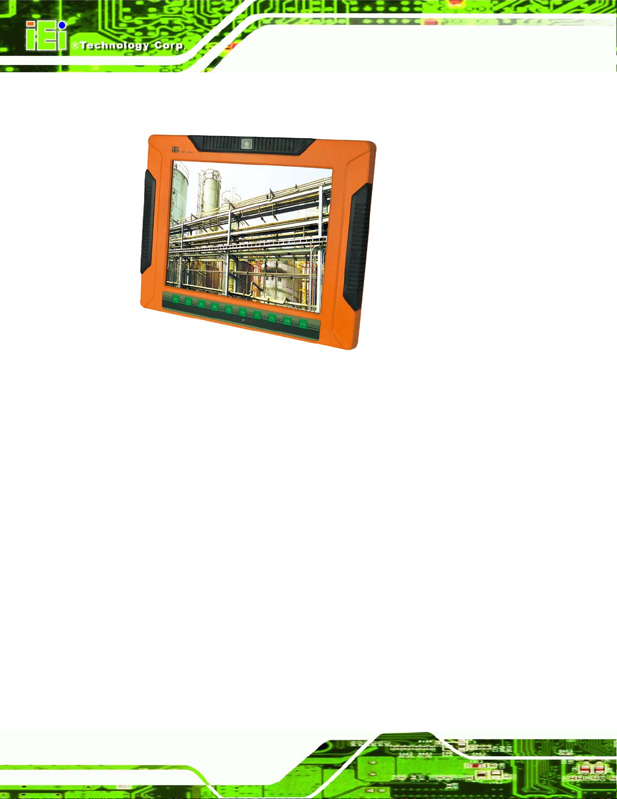
Figure 1-1: UPC-V315-NM70 Panel PC .......................................................................................... 2
Figure 1-2: Front View
Figure 1-3: LED Indicators
Figure 1-4: Bottom View
Figure 1-5: Left Side View
Figure 1-6: Right Side View
Figure 1-7: Rear View
Figure 1-8: Function Key Locations
Figure 1-9: UPC-V315-NM70 Dimensions (mm)
Figure 3-1: Remove the SSD Drive Bay Access Panel
Figure 3-2: Inserting the SSD
Figure 3-3: Securing the SSD
Figure 3-4: SSD Installation
Figure 3-5: Internal USB Port Cover Retention Screws
Figure 3-6: Internal USB Port Location
Figure 3-7: VESA Mount Retention Screw Holes
Figure 3-8: Mounting Brackets (Side Panels)
Figure 3-9: VESA Compliant Arm
.................................................................................................................... 4
............................................................................................................. 5
................................................................................................................ 7
.............................................................................................................. 8
........................................................................................................... 8
..................................................................................................................... 8
............................................................................................. 9
.........................................................................10
.............................................................21
......................................................................................................21
......................................................................................................22
.........................................................................................................22
............................................................23
......................................................................................23
......................................................................24
............................................................................25
................................................................................................25
Figure 3-10: VESA Compliant Stand
Figure 3-11: Wall-mounting Bracket
Figure 3-12: Chassis Support Screws
Figure 3-13: Secure the Panel PC
Figure 3-14: I/O Cover Retention Screws
Figure 3-15: External Peripheral Device Connection ................................................................30
Figure 3-16: Rubber Gasket Removal
Figure 3-17: Rubber Gasket and Cable
Figure 3-18: External Peripheral Device Connection Complete
Figure 3-19: ACC Mode Switch
Figure 3-20: AT/ATX Power Mode Switch
Figure 3-21: CAN-bus Terminal Block Pinouts
Figure 3-22: HDMI Connection
...........................................................................................26
...........................................................................................27
........................................................................................28
...............................................................................................29
...................................................................................30
.........................................................................................30
......................................................................................31
..............................................31
...................................................................................................31
..................................................................................32
..........................................................................32
....................................................................................................33
Page 9

UPC-V315-NM70 Panel PC
Page ix
Figure 3-23: LAN Connection ......................................................................................................34
Figure 3-24: RJ-45 Ethernet Connector
Figure 3-25: 3-pin Terminal Block Pinouts
Figure 3-26: Power Input Connector
Figure 3-27: RJ-45 RS-232 Serial Port Pinout Location
Figure 3-28: DB-9 Connector Pinout Location
Figure 3-29: RJ-45 RS-232 Serial Device Connection
Figure 3-30: RJ-45 RS-422/485 Serial Port Pinout Location
Figure 3-31: DB-9 Connector Pinout Location
Figure 3-32: RJ-45 RS-422/485 Serial Device Connection
Figure 3-33: USB Device Connection
Figure 3-34: VGA Connector
Figure 3-35: VGA Connector
Figure 3-36: Power Connectors
Figure 3-37: ACC On: AT Mode
Figure 3-38: ACC On: ATX Mode
Figure 3-39: ACC On: Switch Between PWR1 and PWR2
Figure 3-40: ACC On: Shutdown
......................................................................................34
................................................................................35
...........................................................................................36
............................................................36
..........................................................................36
...............................................................37
.....................................................38
..........................................................................38
........................................................39
.........................................................................................40
.......................................................................................................41
.......................................................................................................42
..................................................................................................43
...................................................................................................44
.................................................................................................44
........................................................45
.................................................................................................46
Figure 3-41: ACC Off: AT Mode
Figure 3-42: ACC Off: ATX Mode
Figure 3-43: ACC Off: Switch Between PWR1 and PWR2
Figure 3-44: ACC Off: Shutdown
Figure 3-45: Remote Control
Figure B-1: IEI One Key Recovery Tool Menu ...........................................................................89
Figure B-2: Launching the Recovery Tool
Figure B-3: Recovery Tool Setup Menu
Figure B-4: Command Prompt
Figure B-5: Partition Creation Commands
Figure B-6: Launching the Recovery Tool
Figure B-7: Manual Recovery Environment for Windows
Figure B-8: Building the Recovery Partition
Figure B-9: Press Any Key to Continue
Figure B-10: Press F3 to Boot into Recovery Mode
Figure B-11: Recovery Tool Menu
Figure B-12: About Symantec Ghost Window
...................................................................................................47
................................................................................................47
........................................................47
.................................................................................................48
.......................................................................................................49
.................................................................................94
.....................................................................................94
....................................................................................................95
.................................................................................96
.................................................................................98
........................................................98
..............................................................................99
.....................................................................................99
................................................................100
............................................................................................100
.........................................................................101
Page 10

UPC-V315-NM70 Panel PC
Page x
Figure B-13: Symantec Ghost Path ..........................................................................................101
Figure B-14: Select a Local Source Drive
Figure B-15: Select a Source Partition from Basic Drive
Figure B-16: File Name to Copy Image to
Figure B-17: Compress Image
Figure B-18: Image Creation Confirmation
Figure B-19: Image Creation Complete
Figure B-20: Image Creation Complete
Figure B-21: Press Any Key to Continue
Figure B-22: Auto Recovery Utility
Figure B-23: Launching the Recovery Tool
Figure B-24: Auto Recovery Environment for Windows
Figure B-25: Building the Auto Recovery Partition
Figure B-26: Factory Default Image Confirmation
Figure B-27: Image Creation Complete
Figure B-28: Press any key to continue
Figure B-29: Partitions for Linux
Figure B-30: Manual Recovery Environment for Linux
................................................................................102
.......................................................102
................................................................................103
...................................................................................................103
..............................................................................104
....................................................................................104
....................................................................................104
.................................................................................105
...........................................................................................106
.............................................................................106
........................................................106
.................................................................107
..................................................................107
....................................................................................108
...................................................................................108
...............................................................................................110
..........................................................111
Figure B-31: Access menu.lst in Linux (Text Mode)
Figure B-32: Recovery Tool Menu
Figure B-33: Recovery Tool Main Menu
Figure B-34: Restore Factory Default
Figure B-35: Recovery Complete Window
Figure B-36: Backup System
Figure B-37: System Backup Complete Window
Figure B-38: Restore Backup
Figure B-39: Restore System Backup Complete Window
Figure B-40: Symantec Ghost Window
...............................................................112
............................................................................................112
...................................................................................113
.......................................................................................114
...............................................................................115
.....................................................................................................115
....................................................................116
....................................................................................................116
......................................................117
....................................................................................117
Page 11

UPC-V315-NM70 Panel PC
Page xi
List of Tables
Table 1-1: LED Indicators .............................................................................................................. 6
Table 1-2: Function Keys
Table 1-3: System Specifications
Table 3-1: HDMI Pinouts
Table 3-2: LAN Pinouts
Table 3-3: RJ-45 Ethernet Connector LEDs
Table 3-4: RJ-45 RS-232 Serial Port Pinouts
Table 3-5: DB-9 Connector Pinouts
Table 3-6: RJ-45 RS-422/485 Serial Port Pinouts
Table 3-7: DB-9 Connector Pinouts
Table 3-8: USB Port Pinouts (USB 2.0)
Table 3-9: VGA Connector Pinouts
Table 4-1: BIOS Navigation Keys
............................................................................................................... 9
................................................................................................13
..............................................................................................................33
................................................................................................................35
...............................................................................35
.............................................................................36
............................................................................................37
......................................................................38
............................................................................................38
.......................................................................................40
.............................................................................................41
................................................................................................52
Page 12

UPC-V315-NM70 Pane l PC
Page 1
Chapter
1
1 Introduction
Page 13
UPC-V315-NM70 Pane l PC
Page 2
1.1 Overview
Figure 1-1: UPC-V315-NM70 Panel PC
The fanless UPC-V315-NM70 is Intel® Celeron® processor 847 powered panel PC with a
rich variety of func tions and peripherals . The UPC-V315-NM70 p anel PC is desi gned for
easy and simplified integration into various vehicle applications.
An Intel® NM70 express chipset ens ures optimal memory, graphic s, and peripheral I/O
support. The system comes with 2GB of preinstalled DDR3 SDRAM ensuring smooth data
throughputs with reduced bottlenecks and fast system access.
The redundant dual DC power input of the UPC-V315-NM70 increases the reliability of the
system and prevents data loss and system corruption from sudden power failure.
The CAN-bus interfac e allows the UPC-V315-NM70 to communication with vehicles. Four
serial ports and two ex ternal USB 2.0 ports ensure sim plified connectivity to a variety of
external peripheral devices. W i-Fi capabilities and dual RJ-45 GbE connectors ensure
smooth connection of the system to an external LAN.
Page 14
UPC-V315-NM70 Pane l PC
Page 3
1.2 Mode l Variations
The model numbers and model variations are listed below.
Model CPU
UPC-V315-NM70-C/R/2G-R10
1.3 Features
All the UPC-V315-NM70 models feature the following:
Intel Ivy Bridge mobile chipset (NM70)
15'' 400 nits 1024 x 768 LCD with LED backlight
Full IP 65 compliant die-casting aluminum chassis
PCIe mini card expansion
Dual-DC input, 9V ~ 36V and 10.5V ~ 36V, switch automatically
ACC power support
Dual-band 2.4/5GHz Wi-Fi 802.11 a/b/g/n 3T3R MIMO design
Reserved space for 3.75G / HSUPA USB dongle
Optional EM or Mifare RFID reader
Optional Bluetooth module
Built-in 2M pixels webcam with AF, AE and AWB capabilities
Intel® Celeron® Processor 847
CAN-bus interface with isolatio n
F1 ~ F10 function keys with customization options
1.4 Externa l Overview
The panel PC is a rectan gular c ubic str ucture tha t com prises of a scr een, rear p anel, t op
panel, bottom panel and two side panels (left and right). An aluminum frame surrounds the
front screen. The rear panel provides screw holes for a wall-mounting bracket, and an arm
mounting interface. The bottom panel provides access to external interface connectors.
1.4.1 Front Panel
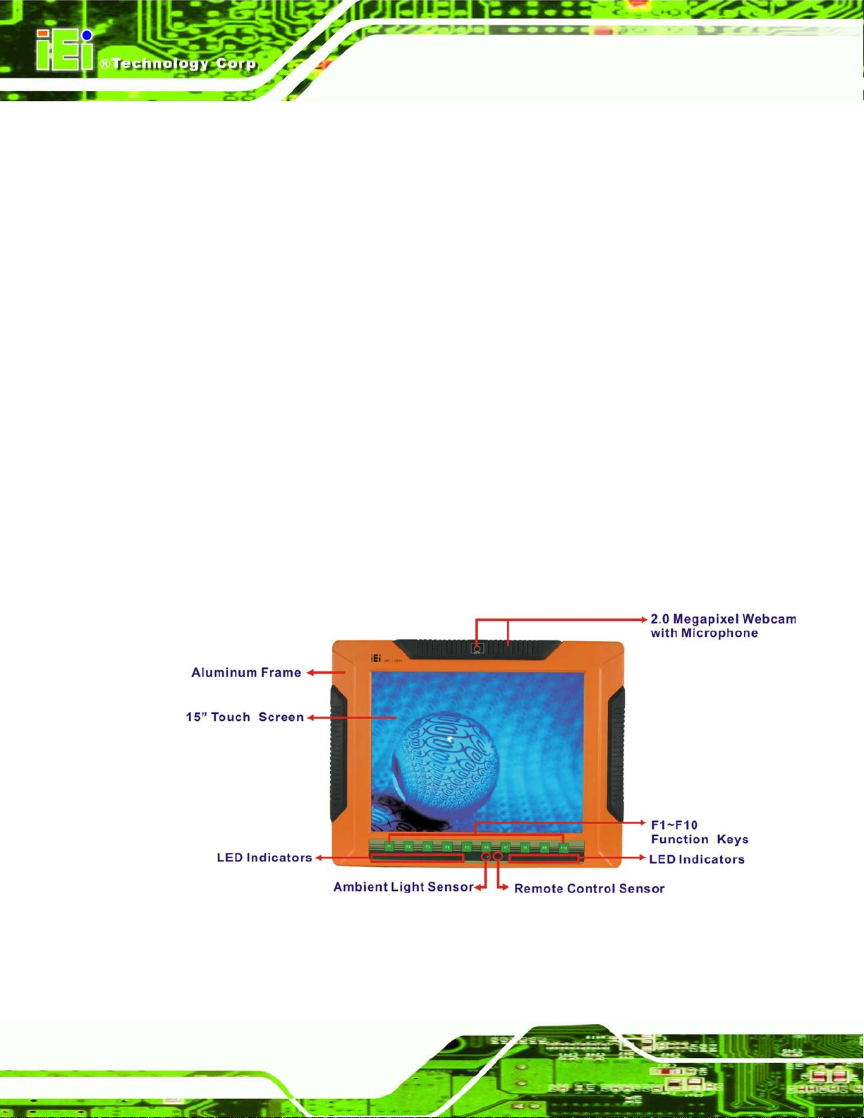
The front side of th e UPC-V315-NM70 is a flat panel TFT LCD screen surr ounded b y an
aluminum fram e. At the top of the front panel features one 2.0 megapixel webcam that
Page 15
UPC-V315-NM70 Pane l PC
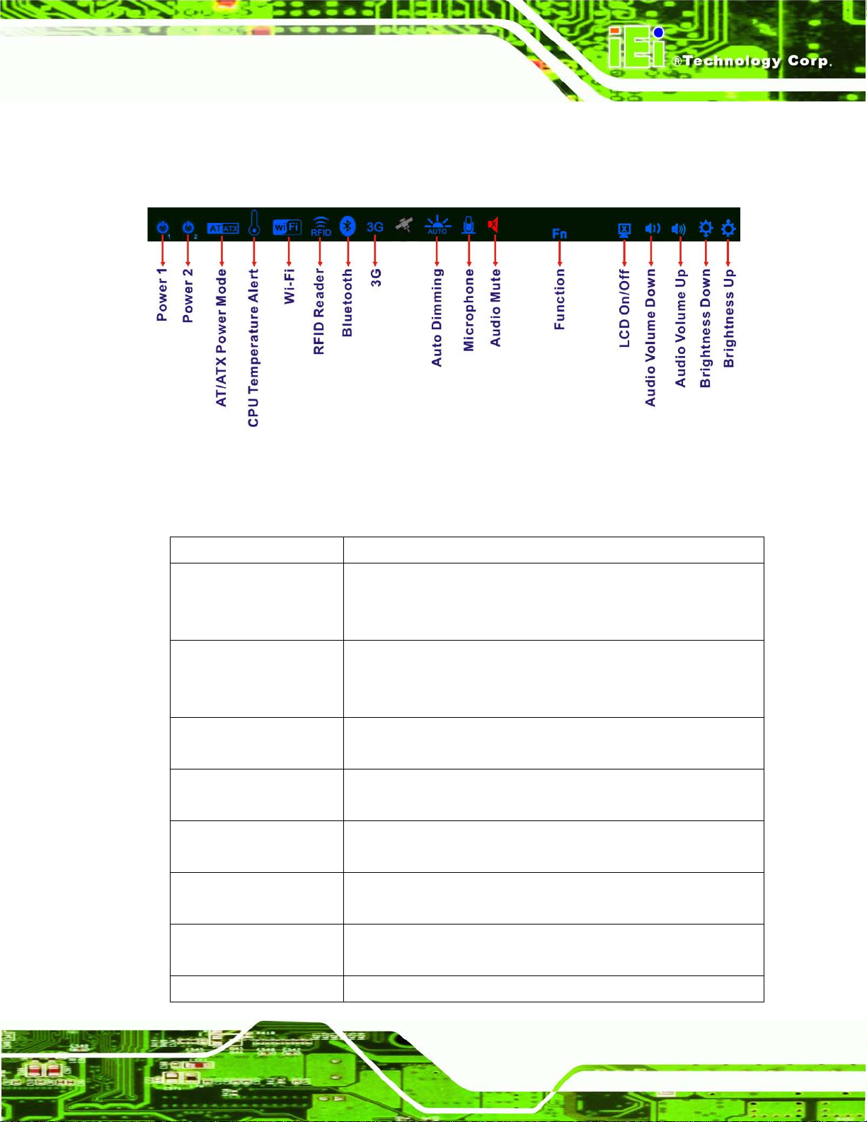
Page 4
supports auto-focus (AF), auto-exposure (AE) and a uto white balance (AWB). The front
panel also has following buttons, LED indicators and sensors:
Buttons: F1~F10 (same as the function key on the keyboard)
LEDs
o Power 1 LED
o Power 2 LED
o AT/ATX power mode LED
o CPU temperature alert LED
o Wi-Fi connection LED
o RFID LED
o Bluetooth LED
o 3G connection LED
o Auto dimming LED
o Microphone on/off LED
o Audio mute LED
Sensors
o Ambient light sensor
o Infrared remote control sensor
Figure 1-2: Front View
Page 16
UPC-V315-NM70 Pane l PC
Page 5
1.4.1.1 LED Indicators
The LED indicators on the front panel of the UPC-V315-NM70 are shown below.
Figure 1-3: LED Indicators
The descriptions of each LED indicator are listed be lo w.
LED Indicator Description
Power 1 Pulsing Orange: Power 1 is the main power and is in standby mode
Solid Orange: Power 1 is the second power and is in standby mode
Solid Blue: Power 1 is providing power to the system
Power 2 Pulsing Orange: Power 2 is the main power and is in standby mode
Solid Orange: Power 2 is the second power and is in standby mode
Solid Blue: Power 2 is providing power to the system
AT/ATX Power Mode Shows the power mode status. Controlled by the AT/ATX power mode
switch.
CPU Temperature Alert Blue: the CPU temperature is normal.
Red: the CPU temperature is too high.
Wi-Fi The Wi-Fi module is enabled or disabled. Controlled by the BIOS (see
Section 4.4.1).
RFID Reader The optional RFID reader is enabled or disabled.
Controlled by the hot keys (see Section 1.4.5).
Bluetooth The Bluetooth module is enabled or disabled .
3G The 3G module is enabled or disabled.
Controlled by the BIOS (see Section 4.4.1).
Page 17
UPC-V315-NM70 Pane l PC
Page 6
Controlled by the BI OS (see Section 4.4.1).
Auto Dimming The auto dimming function is enabled or disabled. Controlled by the
BIOS (4.4.1).
Microphone The microphone is enabled or disabled. Controlled by the BIOS
(Section 4.4.1).
Audio Mute Light on when the audio is turned off.
Controlled by the hot keys (see Section 1.4.5).
Function Shows the status of the function key below the LED indicator. Blinks
LCD on/off
Volume Down
Volume Up
Brightness Down
Brightness Up
Table 1-1: LED Indicators
CAUTION:
If the CPU temperature alert LED shows in red, the user must lower the
environment temperature or close some running applications to cool
down the CPU.
when the corresponding b utton is p us hed .
1.4.2 Bottom Panel
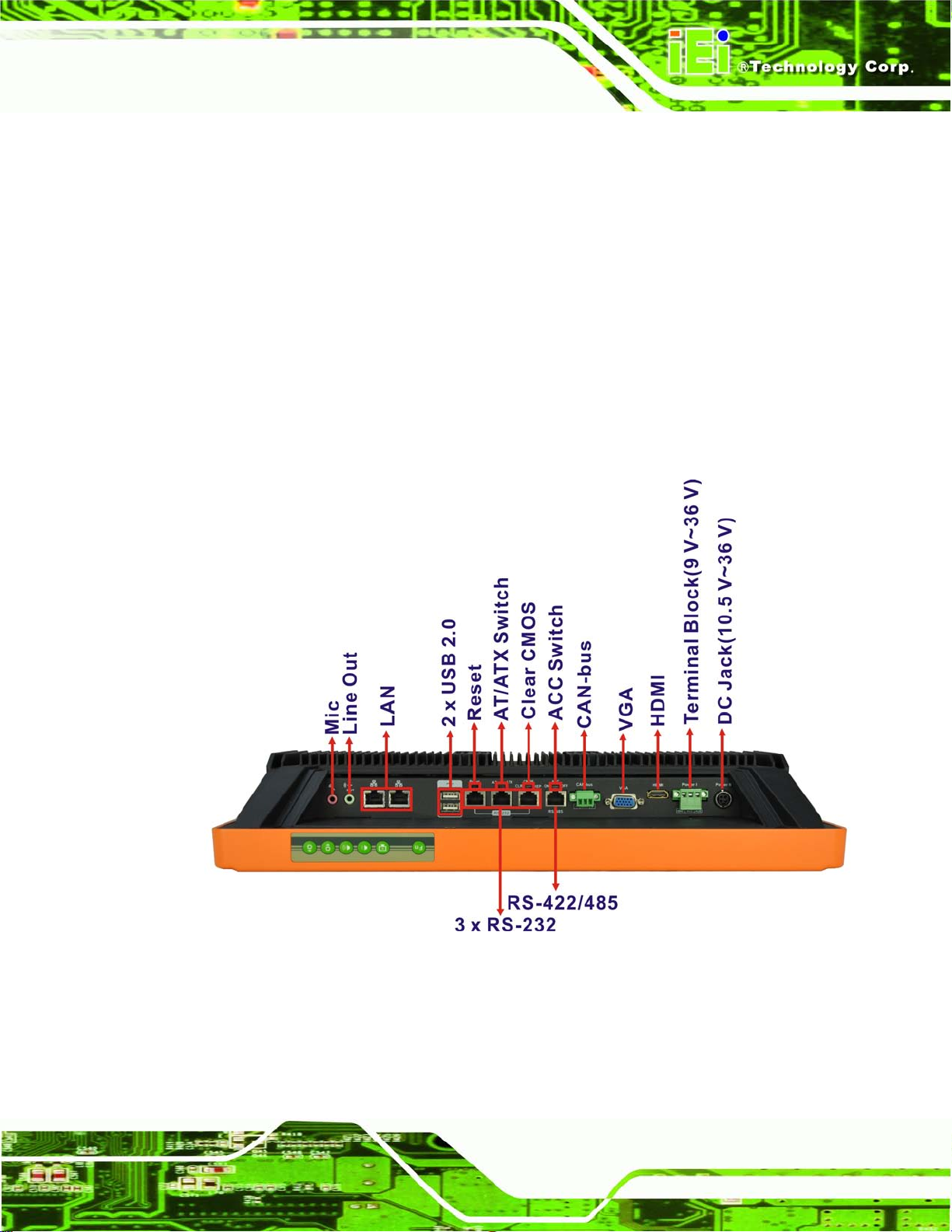
The following is a list of the bottom panel peripheral device connectors on the
UPC-V315-NM70.
1 x 9 V ~ 36 V DC power input terminal block (Power I)
1 x 10.5 V ~ 36 V DC power input connector (Power II)
2 x Audio jacks (Line out ,MIC)
1 x CAN bus connector
Page 18
UPC-V315-NM70 Pane l PC
Page 7
1 x HDMI connector
2 x RJ-45 GbE connectors
3 x RS-232 serial port connectors by RJ-45
1 x RS-422/485 serial port connector by RJ-45
2 x USB 2.0 connectors
1 x VGA connector
The bottom panel also includes the following switches and buttons:
1 x ACC on/off switch
1 x AT/ATX power mode switch
1 x Clear CMOS switch
1 x Reset button
Figure 1-4: Bottom View
Page 19
UPC-V315-NM70 Pane l PC
Page 8
1.4.3 Side Panels
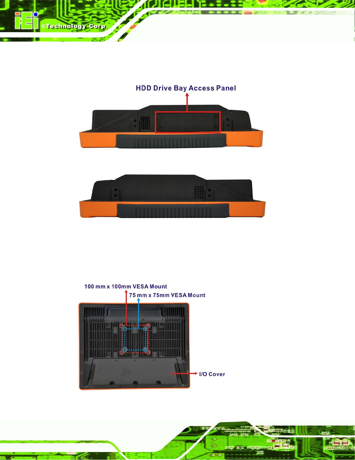
The left side panel of the panel PC provides access to the HDD dive bay. (Figure 1-5)
Figure 1-5: Left Side View
Figure 1-6: Right Side View
1.4.4 Rear Panel
The rear panel has retention screw holes that support a wall-mounting bracket.
Figure 1-7: Rear View
Page 20
UPC-V315-NM70 Pane l PC
Page 9
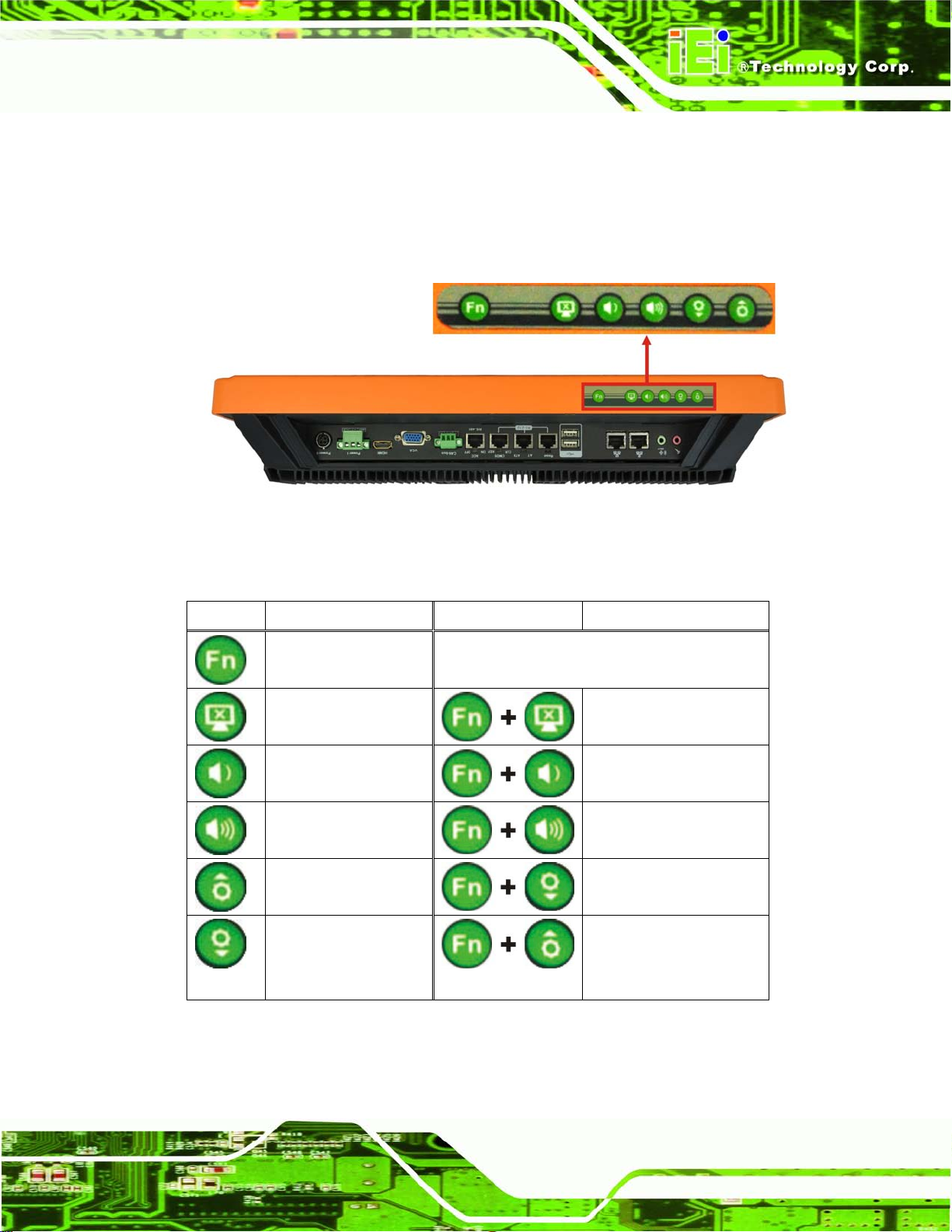
1.4.5 Frame (Function Keys)
An aluminum frame surrounds the TFT LCD screen. The aluminum frame of the
UPC-V315-NM70 contains several function keys that control audio volume, LCD
brightness and some other system components.
Figure 1-8: Function Key Locations
The following table describes the function of these function keys.
Buttons Function Buttons Function
Function
LCD on/off
Audio volume down
Audio volume up
Brightness up
Brightness down
Enable/Disable RFID
Mute audio
Enable/Disable
webcam
Enable/Disable
3G USB 2.0 port
Power on/off
(Turn on: press 3 seconds
Turn off: press 6 seconds)
Table 1-2: Function Keys
Page 21
UPC-V315-NM70 Pane l PC
Page 10
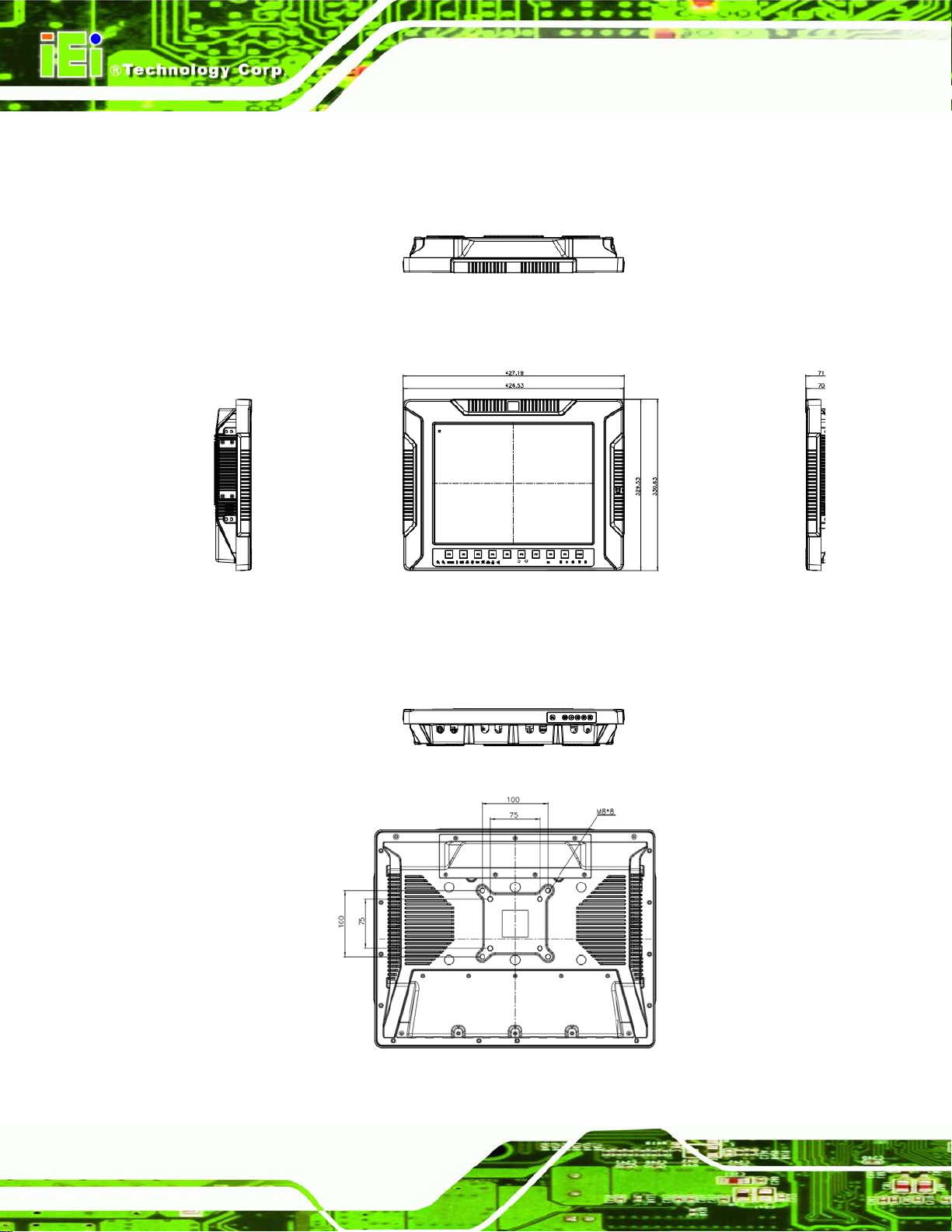
1.5 Dimensions
The dimensions of the UPC-V315-NM70 are shown in Figure 1-9 and listed below.
Figure 1-9: UPC-V315-NM70 Dimensions (mm)
Page 22
UPC-V315-NM70 Pane l PC
Page 11
1.6 Specifications
The technical specifications for the UPC-V315-NM70 system are listed in Table 1-3.
Specification
Display
LCD Size
Max. Resolution
Brightness (cd/m²)
Contrast Ratio
LCD Color
Pixel Pitch (mm)(HxV)
Viewing Angle (V/H)
Backlight MTBF (hrs)
Touch
Touch Screen
UPC-V315-NM70
15”
1024(W) x 768(H)
400
700:1
16.2 M
0.297(H) x 0.297(V)
125°/ 140°
50000
Resistive Type 5-Wire with RS-232 interface
Touch Controller
Motherboard
CPU
Chipset
RAM
Ethernet
Audio Codec
System
DMC 9000
Intel® Celeron® Processor 847
Mobile Intel® NM70 Express Chipset
Built in 1*2GB DDRIII memory
(System Max. 8GB: on board Max. 4GB, socket Max. 4GB)
Intel® 82579 PHY with Intel® iAMT 8.0 supported
Intel® 82583V PCIe controller
Realtek ALC892 HD audio codec
Page 23
UPC-V315-NM70 Pane l PC
Page 12
Audio
Camera
Connectivity
Wireless
Bluetooth
3G
Drive Bay
HDD Driver Bay
SSD
CD-ROM Driver Bay
System Cooling
AMP 3W + 3W (Internal Speaker)
2M Mega Pixels
IEEE 802.11a/b/g/n 3T3R module (WIFI-RT5393-DB-R10)
Bluetooth V2.0+EDR with USB interface (optional)
Reserved USB connector (Optional)
1 x 2.5” SATA SSD
mSATA
N/A
Fanless
Physical
Construction Material
Mounting
Front Panel Color
Dimension (WxHxD) (mm)
Net Weight
Environment
Operation Temperature
Storage Temperature
Operating Humidity
Shock
Vibration
Aluminium alloy
VESA 100mm x100mm or 75mm x 75mm with M8 screws
Orange (Paintone 15C)
427.19 x 330.63 x 71.6
7.97KG
-20°C ~60°C
-30°C ~70°C
5% ~90%, non-condensing
Half-sine wave shock 3G; 11ms; 3 shocks per axis
MIL-STD-810F 514.5C-1 (with CF card or SSD)
IP Rating
Full IP 65
Page 24
UPC-V315-NM70 Pane l PC
Page 13
Power
Adapter
Requirement
I/O Ports and Switches
90 W; 63040-010090-020-RS
Power1:9V~36V(+/-0.3V)
Power2:10.5V~36V(+/-0.3V)
3 x RS-232 (RJ-45)
1 x RS-422/485 (RJ-45)
1 x CAN-BUS
1 x VGA
1 x HDMI port
2 x GbE LAN
2 x USB 2.0
1 x Reset button
1 x Audio jack (Line out ,MIC)
1 x DC Jack (10.5 V ~36 V DC)
1 x Terminal block (9 V ~36 V DC)
1 x AT / ATX mode switch
1 x ACC on/off switch
1 x Clear CMOS switch
1 x Reset button
Table 1-3: System Specifications
Page 25

UPC-V315-NM70 Pane l PC
Page 14
Chapter
2
2 Unpacking
Page 26

UPC-V315-NM70 Pane l PC
Page 15
2.1 Unpacking
To unpack the panel PC, follow the steps below:
WARNING!
The front side LCD screen has a protective plastic cover stuck to the
screen. Only remove the plastic cover after the panel PC has been properly
installed. This ensures the screen is protected during the installation
process.
Step 1: Use box cutters, a knife or a sharp pair of scissors that seals the top side of the
external (second) box.
Step 2: Open the external (second) box.
Step 3: Use box cutters, a knife or a sharp pair of scissors that seals the top side of the
internal (first) box.
Step 4: Lift the monitor out of the boxes.
Step 5: Remove both polystyrene ends, one from each side.
Step 6: Pull the plastic cover off the panel PC.
Step 7: Make sure all the components listed in the packing list are present. Ste p 0:
Page 27
UPC-V315-NM70 Pane l PC
Page 16
2.2 Pack i ng List
The UPC-V315-NM70 panel PC is shipped with the following components:
Quantity Item Imag e
1 UPC-V315-NM70 panel PC
1 Power adapter
(P/N: 63040-010065-010-RS)
1 Power cord
(P/N: 32702-000401-100-RS)
1 Power transfer cord
(P/N: 32702-000300-100-RS)
4 RJ-45 to DB-9 COM port cable
(P/N: 32005-000200-200-RS)
1 Remote control
(P/N: 7Z000-SLPCB001-RS)
8 VESA mount screw (M8)
(P/N: 44325-080081-RS)
Page 28
UPC-V315-NM70 Pane l PC
Page 17
8 VESA mount screw (M4)
(P/N: 44005-040082-RS)
2 Mounting bracket (side panels)
(P/N: 41003-0382C2-00-RS)
1 Screw driver
(P/N: 45019-001004-00)
1 One Key Recover CD
1 Utility CD
If any of these items are missing or damaged, contact the distributor or sales
representative imm ediately.
Page 29

UPC-V315-NM70 Pane l PC
Page 18
Chapter
3
3 Ins ta llation
Page 30

UPC-V315-NM70 Pane l PC
Page 19
3.1 Anti-static Precautions
WARNING:
Failure to take ESD precautions during the maintenance of the EP
series may result in permanent damage to the EP se ries and severe
injury to the user.
Electrostatic discharge (ESD) can cause serious damage to electronic components,
including the UPC-V315-NM70. Dry climates are especially susceptible to ESD. It is
therefore critical tha t whenever the UPC-V315-NM70 is accessed internally, or any other
electrical component is handled, the fol lowing anti-static pr ecautions are strictl y adhered
to.
Wear an anti-static wristband: - Wearing a simple anti-static wristband can
help to prevent ESD from damaging the board.
Self-grounding: - Before handling the board touch any grounded conducting
material. During the time the board is handled, frequently touch any
conducting materials that are connected to the ground.
Use an anti-static pad: - When configuring the UPC-V315-NM70, place it on
an antic-static pad. This reduces the possibility of ESD damaging the
UPC-V315-NM70.
Only handle the edges of the PCB: - When handling the PCB, hold the PCB
by the edges.
3.2 Installation Precautions
When installing the panel PC, please follow the precautions lis te d belo w:
Power turned off: When installing the panel PC, make sure the power is off.
Failing to turn off the power may cause severe injury to the body and/or
damage to the system.
Certified Engineers: Only certified engineers should install and modify
onboard functionalities.
Anti-static Discharge: If a user open the rear panel of the panel PC, to
Page 31

UPC-V315-NM70 Pane l PC
Page 20
any components inside the
configure the jumpers or plug in added peripheral devices, ground themselves
first and wear and anti-static wristband.
3.3 Preinstalled Components
The following components are all preinstalled.
Motherboard
TFT LCD screen
DDR3 memory module
Resistive type touch screen
Stereo speakers
Wireless module
Webcam
CAUTION:
The UPC-V315-NM70 is an IP 65 com pliant panel PC. A user cannot
open the rear cover and install
UPC-V315-NM70. Doing so ma y compromise the s ystem’s waterproof
performance. To install co mponents in the s ystem, pleas e contact the
system vendor, reseller or an IEI sales person directly.
3.4 SSD Ins tallation
To install the SSD into the UPC-V315-NM70, please follow the steps below:
Step 1: Locate the SSD drive bay access panel. The SSD drive bay access panel is
located on the left side panel of the UPC-V315-NM70.
Step 2: Remove the SSD drive bay access panel by removing the four retention
screws.
Page 32

UPC-V315-NM70 Pane l PC
Page 21
with the
to remove the screws on the
NOTE:
Please use the screw driver that comes
UPC-V315-NM70
chassis.
Figure 3-1: Remove the SSD Drive Bay Access Panel
Step 3: Insert the SSD into the bracket as shown.
Figure 3-2: Inserting the SSD
Step 4: Secure the SSD to the bracket using four retention screws.
Page 33

UPC-V315-NM70 Pane l PC
Page 22
Figure 3-3: Securing the SSD
Step 5: Install the SSD. Correctly align the SSD bracket with the system and insert the
SSD bracket into the system.
Figure 3-4: SSD Installation
Step 6: Reinstall the SSD drive bay access panel. Ste p 0:
3.5 Internal USB Devices Ins tallation
The UPC-V315-NM70 has one int ernal USB 2.0 port inside the chas sis. This USB port is
reserved for the 3G USB dongle. To instal l the 3G USB dongle, follow the ins tructions
below.
Page 34

UPC-V315-NM70 Pane l PC
Page 23
Step 1: Remove the internal USB port cover by removing the seven retention screws.
Figure 3-5: Internal USB Port Cover Retention Screws
Step 2: Remove the internal USB port cover and locate the internal USB port.
Figure 3-6: Internal USB Port Locati o n
Step 3: Install the USB dongle. Correctly align the USB dongle with the connector and
insert the USB dongle i nto t he connector.
Step 4: Reinstall the internal USB port cover. S t ep 0:
Page 35

UPC-V315-NM70 Pane l PC
Page 24
3.6 Mounting the System
WARNING:
When mounting the panel PC onto an arm or onto the wall, it is better
to have more than one person to help with the installation to make sure
the panel PC does not fall down and get damaged.
The panel PC is VESA (Video Electronics Stand ards Association) compliant and can be
mounted on an arm, a stand or a bracket with a 100 mm/75 mm interface pad. M8 and M4
mounting screws can b oth be used for VESA mount. The VESA m ount retention screw
holes of the UPC-V315-NM70 are shown i n Figure 3-7.
Figure 3-7: VESA Mount Retention Screw Holes
To enhance the stability, the user can use the m ountin g brack ets , which are shipped with
the UPC-V315-NM70 a nd can be attached on bot h side panels. An additional mounting
device is required for the mounting brackets.
Page 36

UPC-V315-NM70 Pane l PC
Page 25
Figure 3-8: Mounting Brackets (Side Panels)
NOTE:
When mounting the UPC-V315-NM70 on a vehicle, it is recommended
to use the M8 mountin g screws on the real panel. A special mounting
bracket is required for M8 mounting screw. Please contac t IEI f or more
information.
The following installation options are available:
Arm mounting
Stand mounting
The mounting methods are described below.
Wall mounting
3.6.1 Arm Mounting
The UPC-V315-NM70 can be installed on any arm that supports the standard VESA
mounting interface. An example arm is shown below.
Figure 3-9: VESA Compliant Arm
Page 37

UPC-V315-NM70 Pane l PC
Page 26
the arm supports standard VESA mounting. The
To install the UPC-V315-NM70 on the arm, follow the directions below.
NOTE:
Make sure
UPC-V315-NM70 uses a VESA mounting to attach to the arm.
Step 1: The arm is purchased separately. Follow the instructions in the arm's user
manual to securely attach the arm to the wall.
Step 2: Once the mounting arm has been firmly attached to the surface, lift the panel PC
onto the interface pad of the mounting arm.
Step 3: Align the retention screw holes on the mounting arm interface with those in the
panel PC. The arm mount retention screw holes are shown in Figure 3-7.
Step 4: Secure the flat panel PC to the interface pad by inserting four retention screws
through the bottom of the mounting arm interface pad and into the flat panel PC.
Step 0:
3.6.2 Stand Mounting
The UPC-V315-NM70 can be installed on any stand that supports the standard VESA
mounting interface. An example stand is shown below.
Figure 3-10: VESA Compliant Stand
To install the UPC-V315-NM70 on the stand, follow the directions below.
Page 38

UPC-V315-NM70 Pane l PC
Page 27
Step 1: Locate the screw holes on the rear of the UPC-V315-NM70. This is where the
stand bracket will be attached. The stand mount retention screw holes are
shown in Figure 3-7.
Step 2: Align the bracket with the screw holes.
Step 3: Insert the retention screws into the screw holes to secure the bracket to the
UPC-V315-NM70. St ep 0:
3.6.3 Wall Mounting
To mount the panel PC onto the wall, please follow the steps be low.
Step 1: Select the location on the wall for the wall-m ounting br acket.
Step 2: Carefully mark the locations of the four brackets screw holes on the wall.
Step 3: Drill four pilot holes at the marked locations on the wall for the bracket retention
screws.
Step 4: Align the wall-mounting bracket screw holes with the pilot holes.
Step 5: Secure the mounting-bracket to the wall by inserting the retention screws into
the four pilot holes and tightening them (Figure 3-11).
Figure 3-11: Wall-mounting Bracket
Page 39

UPC-V315-NM70 Pane l PC
Page 28
Step 6: Insert the four monitor mounting screws provided in the wall mounting kit into the
four screw holes on the real panel of the flat panel PC and tighten until the screw
shank is secured against the rear panel (Figure 3-12).
Step 7: Align the mounting screws on the monitor rear panel with the mounting holes on
the bracket.
Step 8: Carefully insert the screws through the holes and gently pull the monitor
downwards until the monitor rests securely in the slotted holes (Figure 3-12).
Ensure that all four of the mounting screws fit snuggly into their respective
slotted holes.
Figure 3-12: Chassis Support Screws
NOTE:
In the diagram below the bracket is already installed on the wall.
Page 40

UPC-V315-NM70 Pane l PC
Page 29
Step 9: Secure the panel PC by fastening the retention screw of the wall-mounting
bracket. (Figure 3-13).
Figure 3-13: Secure the Panel PC
3.7 Bottom Panel Connectors
The bott om panel of the UPC-V315-NM70 contains I/O connectors, switches an d a reset
button. These connectors are protected by an I/O cover. Detailed descriptions of the
connectors can be found in the subsections below.
3.7.1 External Peripheral Device Connection
To install external peripheral devices to the UPC-V315-NM70, please follow the steps
below.
Step 1: Remove the I/O cover by removing the ten retention screws as shown in Figure
3-14.
Page 41

UPC-V315-NM70 Pane l PC
Page 30
Figure 3-14: I/O Cover Retention Screws
Step 2: Connect the cable from the external peripheral device to the corresponding
connector of the UPC-V315-NM70 (Figure 3-15).
Figure 3-15: External Peripheral Device Connection
Step 3: Take out a rubber gasket from the I/O cover (Figure 3-16).
Figure 3-16: Rubber Gasket Removal
Step 4: Remove some rubber rings from the gasket to make the gasket fit perfectly to
the size of the cable (Figure 3-17).
Page 42

UPC-V315-NM70 Pane l PC
Page 31
Figure 3-17: Rubber Gasket and Cable
Step 5: Repeat steps to other connected cables.
Step 6: Install the I/O cover and make sure each rubber gasket snaps into place tightly.
Step 7: Secure the I/O cover by the previously removed retention screws.
Figure 3-18: External Peripheral Device Connection Complete
3.7.2 ACC Mode Selection
The ACC mode can be turned on or off. The setting is made through the ACC mode switch
on the bottom panel as shown below.
Figure 3-19: ACC Mode Switch
3.7.3 AT/ATX Power Mode Selection
The UPC-V315-NM70 supports both AT and ATX power modes. The setting can be made
through the AT/ATX power mode switch on the bottom panel as shown below.
Page 43

UPC-V315-NM70 Pane l PC
Page 32
Figure 3-20: AT/AT X Power Mode Switch
3.7.4 Audio Connectors
The audio jacks connect to external audio devices.
Microphone (Pink): Connects a microphone.
Line Out port (Green): Connects to a headphone or a speaker. With
multi-channel configurations, this port can also connect to front speakers.
3.7.5 CAN-bus Terminal Block
There is one 3-pin CAN-bus terminal block. The pinouts are shown in Figure 3-21
Figure 3-21: CAN-bus Terminal Block Pinouts
3.7.6 HDMI Connector
The HDMI connector trans mits a digital signal to compati ble HDMI display devices such
as a TV or computer s creen. To connec t the HDMI ca ble to the UPC-V315-NM70, follo w
the steps below.
Step 1: Locate the HDMI connector. The location is shown in Chapter 1.
Step 2: Align the connector. Align the HDMI connector with the HDMI port. Make sure
the orientation of the connector is correct.
Page 44

UPC-V315-NM70 Pane l PC
Page 33
Figure 3-22: HDMI Connection
Step 3: Insert the HDMI connector. Gently insert the HDMI connector. The connector
should engage with a gentle push. If the connector does not insert easily, check
again that the connector is aligned correctly, and that the connector is being
inserted with the right way up.
The pinouts of the HDMI connector is shown below.
Pin Description Pin Description
1 HDMI_DATA2 2 GND
3 HDMI_DATA2# 4 HDMI_DATA1
5 GND 6 HDMI_DATA1#
7 HDMI_DATA2 8 GND
9 HDMI_DATA2# 10 HDMI_CLK
11 GND 12 HDMI_CLK#
13 NC 14 NC
15 HDMI_SCL 16 HDMI_SDA
17 GND 18 +5V
19 HDMI_HPD
Table 3-1: HDMI Pinouts
Page 45

UPC-V315-NM70 Pane l PC
Page 34
3.7.7 LAN Connector
To connect the UPC-V315-NM70 to a network through the RJ-45 LAN c onnector, follow
the steps below.
Step 1: Locate the RJ-45 connector. The location of the RJ-45 connectors is shown in
Figure 1-4.
Step 2: Align the connectors. Align the RJ-45 connector on the LAN cable with one of
the RJ-45 connectors on the UPC-V315-NM70. Se e Figure 3-23.
Figure 3-23: LAN Connection
Step 3: Insert the LAN cable RJ-45 connector. Once aligned, gently insert the LAN
cable RJ-45 connector into the on-board RJ-45 connector.
Figure 3-24: RJ-45 Ethernet Connector
Page 46

UPC-V315-NM70 Pane l PC
Page 35
The pinouts of the RJ-45 LAN connector is shown below.
Pin Description Pin Description
1 MDI0+ 2 MDI03 MDI1+ 4 MDI15 MDI2+ 6 MDI27 MDI3+ 8 MDI3-
Table 3-2: LAN Pinouts
The RJ-45 Ethernet connector has two status LEDs, one green and one yellow. See
Figure 3-24.
LED Description LED Description
A on: linke d
blinking: data is being sent/received
Table 3-3: RJ-45 Ethernet Connector LEDs
3.7.8 Power Input, 3-pin Terminal Block
The power connect or connects the le ads of a 9V~36V DC power su pply into t he t erminal
block. Make sure t hat the po wer and ground wires are att ached to th e correct so ckets of
the connector.
B off: 10 Mb/s
green: 100 Mb/s
orange: 1000 Mb/s
Figure 3-25: 3-pin Terminal Block Pinouts
3.7.9 Power Input, 4-pin DIN Connector
The power connector connects to the 10.5 V ~ 36 V DC power adapter.
Page 47

UPC-V315-NM70 Pane l PC
Page 36
Figure 3-26: Power Input Connector
3.7.10 RJ-45 RS -232 Serial Port
RS-232 serial port devices can be attached to the RJ-45 RS-232 serial ports on the
bottom panel. The pinouts of the RJ-45 RS-232 serial port is shown below.
Figure 3-27: RJ-45 RS-232 Serial Port Pinout Location
Pin Description Pin Description
1 RI 5 RTS
2 DTR 6 RX
3. CTS 7 DSR
4. TX 8 DCD
Table 3-4: RJ-45 RS-232 Ser ial Po rt Pinouts
Figure 3-28: DB-9 Connector Pinout Location
Pin Description Pin Description
1 DCD 6 DSR
2 RX 7 RTS
Page 48

UPC-V315-NM70 Pane l PC
Page 37
Pin Description Pin Description
3 TX 8 CTS
4 DTR 9 RI
5 GND
Table 3-5: DB-9 Connector Pinouts
To install the RS-232 devices, follow the steps below.
Step 1: Locate the RJ-45 RS-232 connector. The location of the RJ-45 RS-232
connector is shown in Figure 1-4.
Step 2: Insert the RJ-45 connector. Insert the RJ-45 connector on the RJ-45 to DB-9
COM port cable to the RJ-45 RS-232 connector on the UPC-V315-NM70. See
Figure 3-29.
Figure 3-29: RJ-45 RS-232 Serial Devi ce Connection
Step 3: Insert the serial connector. Insert the DB-9 connector of a serial device into
Step 4: Secure the connector. Secure the serial device connector to the external
3.7.11 RJ-45 RS-422/485 Serial Port
A RS-422/485 serial port device can be connected to the RS-422/485 s erial port on the
bottom panel. The pinouts of the RS-422/485 serial port is shown below.
the DB-9 connector on the RJ-45 to DB-9 COM port cable.
interface by tightening the two retention screws on either side of the connector.
Page 49

UPC-V315-NM70 Pane l PC
Page 38
Figure 3-30: RJ-45 RS-422/485 Serial Port Pinout Location
Pin Description Pin Description
1 N/A 5 N/A
2 TXD485# 6 RXD485#
3. N/A 7 N/A
4. TXD485+ 8 RXD485+
Table 3-6: RJ-45 RS-422/485 Serial Port Pinouts
Figure 3-31: DB-9 Connector Pinout Location
Pin Description (RS-422) Description (RS-485)
1 RXD422+ N/A
2 RXD422# N/A
3 TXD422+ TXD485+
4 TXD422# TXD485#
5 N/A N/A
6 N/A N/A
7 N/A N/A
8 N/A N/A
9 N/A N/A
Table 3-7: DB-9 Connector Pinouts
To install the RS-422/485 devices, follow the steps below.
Page 50

UPC-V315-NM70 Pane l PC
Page 39
Step 5: Locate the RJ-45 RS-422/485 connector. The location of the RJ-45
RS-422/485 connector is shown in Figure 1-4.
Step 6: Insert the RJ-45 connector. Insert the RJ-45 connector on the RJ-45 to DB-9
COM port cable to the RJ-45 RS-422/485 connector on the UPC-V315-NM70.
See Figure 3-29.
Figure 3-32: RJ-45 RS-422/485 Serial Device Connection
Step 7: Insert the serial connector. Insert the DB-9 connector of a serial device into
the DB-9 connector on the RJ-45 to DB-9 COM port cable.
Step 8: Secure the connector. Secure the serial device connector to the external
interface by tightening the two retention screws on either side of the connector.
3.7.12 US B Connectors
The USB ports are for att aching USB p eripheral devices to the system. To install a USB
device, follow the steps below.
Step 1: Locate the USB connectors. The locations of the USB connectors are shown
in Figure 1-4.
Step 2: Align the connectors. Align the USB device connector with one of the
connectors. See Figure 3-33.
Page 51

UPC-V315-NM70 Pane l PC
Page 40
Figure 3-33: USB Device Connection
Step 3: Insert the device connector. Once align ed, ge ntly insert the USB device
connector into the on-board connector.
The pinouts of the USB ports are shown below.
Pin Description Pin Description
1 +5V 5 +5V
2 USB_PN0 6 USB_PN1
3 USB_PP0 7 USB_PP1
4 GND 8 GND
Table 3-8: USB Port Pinouts (USB 2.0)
3.7.13 VGA Connector
The VGA connector connects to a m onitor that accepts VGA video in put. The pinouts of
the VGA connector is shown below.
Page 52

UPC-V315-NM70 Pane l PC
Page 41
Figure 3-34: VGA Connector
Pin Description Pin Description
1 RED 2 GREEN
3 BLUE 4 NC
5 GND 6 GND
7 GND 8 GND
9 VCC / NC 10 GND
11 NC 12 DDC DA T
13 HSYNC 14 VSYNC
15 DDCCLK
Table 3-9: VGA Connector Pinouts
To connect the UPC-V315-NM70 to a monitor that ac cepts VGA video input, follo w the
steps below,
Step 1: Locate the female DB-15 connector. The location of the female DB-15
connector is shown in Figure 1-4.
Step 2: Align the VGA connector. Align the male DB-15 connector on the VGA screen
cable with the female DB-15 connector on the external peripheral interface.
Step 3: Insert the VGA connector. Once the connectors are properly aligned with the
insert the male connector from the VGA screen into the female connector on the
UPC-V315-NM70. See Figure 3-35.
Page 53

UPC-V315-NM70 Pane l PC
Page 42
Figure 3-35: VGA Connector
CAUTION:
It is suggested that not to open the rear cover and replace any
components. If the components fail, it must be shipped b ack to IEI to
be replaced. If the system has failed, please contact the system
vendor, reseller or an IEI sales person directly.
Page 54

UPC-V315-NM70 Pane l PC
Page 43
3.8 Redundant Power
The UPC-V315-NM70 is a system that s upports redundant power. The redundant power
input increases the reliability of the system while preventing data loss and system
corruption from sudden power failure. The system can instantly and uninterruptedly switch
to the second power input when the main power is unavailable or in low voltage capacity.
There are two power connectors on the bottom panel. Power 1 connector is a 3-pin
terminal block that s upports ACC On signal. Power 2 connector is a DIN con nector that
can directly connect to a power adapter. The supported power input voltages are:
Power 1 (Terminal block): 9 V (+/-0.3 V) ~ 36 V
Power 2 (DC jack): 10. 5 V (+/-0.3 V) ~ 36 V
Figure 3-36: Power Connectors
When the system is in ACC On mode, the main power input is from the Power 1 connector.
When the system is in ACC Off mode, the main power input is from the Power 2 connector.
The ACC on/off mode is selected by the ACC on/off switch on the bottom panel.
(Figure 3-19).
The following sections describe ho w redundant power works in ACC On mode and A CC
Off mode.
Page 55

UPC-V315-NM70 Pane l PC
Page 44
3.8.1 AC C ON
The ACC On mode is des igned for vehicle applicatio ns. W hen the UPC-V315-NM70 is in
ACC On mode, the main po wer input is the Power 1 connector a nd the backup power is
from the Power 2 connector.
3.8.1.1 Boot-up
When both power con nectors are connec ted to the power source wit h over 9 V, the two
NOTE:
In ACC On mode, t he Po wer 1 co nnector m ust c onnect to the ACC on
signal to be able to control system power.
power LEDs on the front panel rem ain off until the ACC ON signal jumps from low to
high. The user can choose AT power mode or AT X power mode to cont rol the system .
The following flow diagrams show the boot-up process and the LED status in AT and ATX
power modes.
Figure 3-37: ACC O n: AT Mode
Figure 3-38: ACC O n: ATX Mode
Page 56

UPC-V315-NM70 Pane l PC
Page 45
3.8.1.2 Switch to Backup Power
During operation, s ystem power will switch f rom Power 1 to Power 2 automatically when
the following situations occur:
Power 1 < 9V and Power 2 > 10.5V
Power 1 > 9V, but the ACC ON signal jump from high to low
Power 1 is unplugged and Power 2 > 10.5V
The following flow diagram shows how the power is switched between Power 1 and
Power 2 and their LED statuses.
Figure 3-39: ACC On: Switch Between PWR1 and PWR2
3.8.1.3 Shutdown
The system will shutdown in the following situations:
Power 1 < 9V and Power 2 < 10.5V
Power 1 > 9V, Power 2 < 10.5V and ACC ON signal jump from high to low
Press buttons for 6 seconds
The following flow diagram shows the system shutdown process and the LED statuses.
Page 57

UPC-V315-NM70 Pane l PC
Page 46
Figure 3-40: ACC On: Shutdown
NOTE:
To turn on the system in ATX power mode, press the
button for three seconds. Press these t wo buttons for six seconds to
turn off the system.
3.8.2 AC C OFF
When the UPC-V315-NM70 is in ACC Off mode, the main power input is the Power 2
connector and the backup power is from the Power 1 connector.
3.8.2.1 Boot-up
When both power con nectors are connec ted to the power source with over 9 V, the two
power LEDs on the f ront panel turn on. The user can choose AT power mode or ATX
power mode to control the system. The following flow diagrams show the boot-up process
and the LED status in AT and ATX power modes.
Page 58

UPC-V315-NM70 Pane l PC
Page 47
Figure 3-41: ACC Off: AT Mode
Figure 3-42: ACC Off: AT X Mode
3.8.2.2 Switch to Backup Power
During operation, system power switches from Power 2 to Power 1 automatically when the
following situations occur:
Power 2 < 10.5V and Power 1 > 9V
Power 2 is unplugged and Power 1 > 9V
The following flow diagram shows how the power is switched between Power 2 and
Power 1 and their LED statuses.
Figure 3-43: ACC Off: Switch Between PWR1 and PWR2
Page 59

UPC-V315-NM70 Pane l PC
Page 48
3.8.2.3 Shutdown
The system will shutdown in the following situations:
Power 2 < 10.5V and Power 1 < 9V
Press
The following flow diagram shows the system shutdown process and the LED statuses.
Figure 3-44: ACC Off: Shutdown
buttons for 6 seconds
NOTE:
The power LED turns of f when the po wer cable is unplugged from the
system.
Page 60

UPC-V315-NM70 Pane l PC
Page 49
3.9 Remote Control
The UPC-V315-NM70 comes with a remote control for eas y configuration. Figure 3-45
shows the remote control and its function keys.
Figure 3-45: Remote Control
System On/Off: Press this button to turn the UPC-V315-NM70 on or off.
LCD On/Off. Press this button to turn the LCD monitor on or off.
Auto-Dimming. Press this button to turn the auto-dimming function on or off.
Brightness. Use these control buttons to adjust the brightness of the LCD
screen.
Volume. Press these buttons to adj us t the audio vo lu me level.
Page 61

UPC-V315-NM70 Pane l PC
Page 50
Chapter
4
4 BIOS
Page 62

UPC-V315-NM70 Pane l PC
Page 51
4.1 Introduction
The BIOS is programmed onto the BIOS chip. The BIOS setup program allows changes to
certain system settings. This chapter outlines the options that can be changed.
4.1.1 Starting Se tup
The UEFI BIOS is activate d when the computer is turned on. The setup program c an be
activated in one of two ways.
1. Press the DEL or F2 key as soon as the system is turned on or
2. Press the DEL or F2 key when the “Press DEL or F2 to enter SETUP”
message appears on the screen.
If the message disappears before the DEL or F2 key is pressed, restart the computer and
try again.
4.1.2 Using S etup
Use the arrow keys to highlight items, press ENTER to select, use the PageUp and
PageDown keys to c hange entries, press F1 for help and press E
keys are shown in.
Key Function
Up arrow Move to previous item
Down arrow Move to next item
Left arrow Move to the item on the left hand side
Right arrow Move to the item on the right hand side
+ Increase the numeric value or make changes
- Decrease the numeric value or make changes
Page Up key Move to the previous page
Page Dn key Move to the next page
SC to quit. Navigation
Page 63

UPC-V315-NM70 Pane l PC
Page 52
Key Function
Esc key Main Menu – Quit and not save changes into CMOS
F1 General help, only for Status Page Setup Menu and Option
F2 Load previous values
F3 Load optimized defaults
F4 Save changes and Exit BIOS
Table 4-1: BIOS Navigation Keys
4.1.3 Get t ing Help
Status Page Setup Menu and Option Page Setup Menu -Exit current page and return to Main Menu
Page Setup Menu
When F1 is pressed a sm all help windo w describing the a ppropriate k eys to use and th e
possible selections for the highlighted item appears. To exit the Help Window press E
the F1 key again.
4.1.4 Una ble to Reboot after Configuration Changes
If the computer cannot boot after changes to the system configuration is made, CMOS
defaults. Use the jumper described in Chapter 4.
4.1.5 BIOS Me n u Bar
The menu bar on top of the BIOS screen has the following main items:
Main – Changes the basic system configuration.
Advanced – Changes the advanced system settings.
Chipset – Changes the chipset settings.
Boot – Changes the system boot configuration.
Security – Sets User and Supervisor Passwords.
SC or
Save & Exit – Selects exit options and loads default settings
The following secti ons completely describe the configuration options found in the menu
items at the top of the BIOS screen and listed above.
Page 64

UPC-V315-NM70 Pane l PC
Page 53
Aptio Setup Utility – Copyright (C) 2012 American Megatrends, Inc.
Main
Advanced
Chipset
Boot
Security
Save & Exit
Access Level Administrator
Version 2.15.1229. Copyright (C) 2012 American Megatrends, Inc.
4.2 Ma in
The Main BIOS menu (BIOS Menu 1) appears when the BIOS Setup program is entered.
The Main menu gives an overview of the basic system information.
BIOS Information
BIOS Vendor American Megatrends
Core Version 4.6.5.3
Compliancy UEFI 2.3; PI 1.2
Project Version SE81AR10.ROM
Build Date and Time 04/12/2013 13:47:22
IWDD Vender ICP
IWDD Version SE81ER10.BIN
Processor Information
Name SandyBridge
Brand String Intel(R) Celeron(R) CPU
Frequency 1100 MHz
Processor ID 206a7
Stepping D2
Number of Processors 2Core(s) / 2Thread(s)
Microcode Revision 28
GT Info GT2 (800 MHz)
IGFX VBIOS Version 2137
Memory RC Version 1.2.2.0
Total Memory 2048 MB (DDR3)
Memory Frequency 1333 MHz
PCH Information
Name PantherPoint
Stepping 04/C1
LAN PHY Revision C0
ME FW Version 8.1.0.1248
ME Firmware SKU 1.5MB
SPI Clock Frequency
DOFR Support Supported
Read Status Clock Frequnecy 33 MHz
Write Status Clock Frequnecy 33 MHz
Fast Read Status Clock Frequnecy 33 MHz
System Date [Mon 04/22/2013]
System Time [15:10:27]
Set the Date. Use Tab to
switch between Data
elements.
----------------------
: Select Screen
↑ ↓: Select Item
Enter: Select
+/-: Change Opt.
F1: General Help
F2: Previous Values
F3: Optimized Defaults
F4: Save & Exit
ESC: Exit
BIOS Menu 1: Main
Page 65

UPC-V315-NM70 Pane l PC
Page 54
System Overview
The system overview lists a brief s ummary of the BIOS. T he fields in s ystem overview
cannot be changed. The items shown in the system overview include:
BIOS Information
IWDD Information
Processor Information
Memory Information
PCH Information
ME Information
SPI Clock Frequency
The Main menu has two user configurable fields:
System Date [xx/xx/xx]
Use the System Date option to set the system date. Manuall y enter the day, m onth and
year.
System Time [xx:xx:xx]
Use the System Time option to set the s ystem time. Manuall y enter the hours, minutes
and seconds.
4.3 Advanced
Use the Advanced menu (BIOS Menu 2) to configure the CPU and peripheral devices
through the following sub-menus:
WARNING!
Setting the wrong values in the sections below m ay cause the s ystem
to malfunction. Mak e sure that the settings m ade are compatible with
the hardware.
Page 66

UPC-V315-NM70 Pane l PC
Page 55
Aptio Setup Utility – Copyright (C) 2012 American Megatrends, Inc.
Main
Advanced
Chipset
Boot
Security
Save & Exit
ESC: Exit
Version 2.15.1229. Copyright (C) 2012 American Megatrends, Inc.
Aptio Setup Utility – Copyright (C) 2012 American Megatrends, Inc.
Advanced
ESC: Exit
Version 2.15.1229. Copyright (C) 2012 American Megatrends, Inc.
> ACPI Settings
> RTC Wake Settings
> CPU Configuration
> SATA Configuration
> USB Configuration
> F81866 Super IO Configuration
> F81866 H/M Monitor
> Serial Port Console Redirection
> iEi Feature
BIOS Menu 2: Advanced
4.3.1 ACP I Settings
The ACPI Settings menu (BIOS Menu 3) configures the Advanced Configuration and
Power Interface (ACPI) options.
System ACPI Parameters
----------------------
: Select Screen
↑ ↓: Select Item
Enter: Select
+/-: Change Opt.
F1: General Help
F2: Previous Values
F3: Optimized Defaults
F4: Save & Exit
ACPI Settings
ACPI Sleep State [S1 (CPU Stop Clock)]
BIOS Menu 3: ACPI Configuration
Select ACPI sleep state
the system will enter
when the SUSPEND button
is pressed.
----------------------
: Select Screen
↑ ↓: Select Item
Enter: Select
+/-: Change Opt.
F1: General Help
F2: Previous Values
F3: Optimized Defaults
F4: Save & Exit
Page 67

UPC-V315-NM70 Pane l PC
Page 56
CPU Stop
3 (Suspend to
. Power to the RAM is maintained. The
Aptio Setup Utility – Copyright (C) 2012 American Megatrends, Inc.
Advanced
ESC: Exit
Version 2.15.1229. Copyright (C) 2012 American Megatrends, Inc.
ACPI Sleep State [S1 (CPU Stop Clock)]
Use the ACPI Sleep State option to specif y the sleep state th e system enters when it is
not being used.
S1 (
Clock)
S
RAM)
DEFAULT
The system enters S1 (POS) sleep state. The
system appears off. The CPU is stopped; RAM is
refreshed; the system is running in a low power
mode.
The caches are flushed and the C PU is pow ered
off
computer returns slower to a working state, but
more power is saved.
4.3.2 RTC Wake Settings
The RTC Wake Settings menu (BIOS Menu 4) enables the system to wake at the
specified time.
Wake system with Fixed Time [Disabled]
Enable or disable System
wake on alarm event. When
enabled, System will
wake on the
date::hr::min::sec
specified
----------------------
: Select Screen
↑ ↓: Select Item
Enter: Select
+/-: Change Opt.
F1: General Help
F2: Previous Values
F3: Optimized Defaults
F4: Save & Exit
BIOS Menu 4: RTC Wake Settings
Page 68

UPC-V315-NM70 Pane l PC
Page 57
every day at the specified time. Besides, the
Wake s ystem with Fixed Time [Dis abled]
Use the Wake system w ith Fixed Time option to enable or disa ble the s ystem wake on
alarm event.
Disabled D
Enabled
EFAULT
4.3.3 CP U Configuration
The real time clock (RTC) cannot generate a wak e
event
If selected, the Wake up every da y option appears
allowing you to enable to disable the system to wake
following options appear with values that can be
selected:
Wake up date
Wake up hour
Wake up minute
Wake up second
After setting the alarm, the computer turns itself on
from a suspend state when the alarm goes off.
Use the CPU Configuration menu (BIOS Menu 5) to view det ailed C PU spec if ic at ions or
enable the Intel Virtualization Technology.
Page 69

UPC-V315-NM70 Pane l PC
Page 58
Aptio Setup Utility – Copyright (C) 2012 American Megatrends, Inc.
Advanced
Version 2.15.1229. Copyright (C) 2012 American Megatrends, Inc.
CPU Configuration
Intel(R) Celeron(R) CPU 847 @ 1.10GHz
CPU Signature 206a7
Microcode Patch 28
Max CPU Speed 1100 MHz
Min CPU Speed 800 MHz
CPU Speed 1100 MHz
Processor Cores 2
Intel HT Technology Not Supported
Intel VT-x Technology Supported
Intel SMX Technology Not Supported
64-bit Supported
L1 Data Cache 32 kB x 2
L1 Code Cache 32 kB x 2
L2 Cache 256 kB x 2
L3 Cache 2048 kB
Intel Virtualization Technology [Disabled]
BIOS Menu 5: CPU Configuration
When enabled, a VMM can
utilize the additional
hardware capabilities
provided by Vanderpool
Technology
----------------------
: Select Screen
↑ ↓: Select Item
Enter: Select
+/-: Change Opt.
F1: General Help
F2: Previous Values
F3: Optimized Defaults
F4: Save & Exit
ESC: Exit
Intel Virtualization Technology [Disabled]
Use the Intel Virtualization Technology option to enable or disable virtualization on the
system. When com bined with third par ty software, Intel® Virt ualization tec hnolog y allows
several OSs to run on the same system at the same time.
Disabled DEFAULT
Enabled
Disables Intel Virtualization
Technology.
Enables Intel Virtualization Technology.
Page 70

UPC-V315-NM70 Pane l PC
Page 59
Aptio Setup Utility – Copyright (C) 2012 American Megatrends, Inc.
Advanced
Version 2.15.1229. Copyright (C) 2012 American Megatrends, Inc.
4.3.4 S ATA Configuration
Use the SATA Configuration menu (BIOS Menu 6) to change and/or set the
configuration of the SATA devices installed in the system.
SATA Mode Selection [IDE]
Serial ATA Port 1 Empty
BIOS Menu 6: SATA Configuration
SATA Mode Selection [IDE]
Use the SATA Mode Selection option to configure SATA devices as normal IDE devices.
IDE DEFAULT
Configures SATA devices as normal IDE device.
Determines how SATA
controller(s) operate.
---------------------
: Select Screen
↑ ↓: Select Item
Enter: Select
+/-: Change Opt.
F1: General Help
F2: Previous Values
F3: Optimized Defaults
F4: Save & Exit
ESC: Exit
AHCI
Configures SATA devices as AHCI device.
Page 71

UPC-V315-NM70 Pane l PC
Page 60
Aptio Setup Utility – Copyright (C) 2012 American Megatrends, Inc.
Advanced
ESC: Exit
Version 2.15.1229. Copyright (C) 2012 American Megatrends, Inc.
4.3.5 USB Configuration
Use the USB Configuration menu (BIOS Menu 7) to read USB configurati on inf ormation
and configure the USB settings.
USB Configuration
USB Devices:
1 Keyboard, 2 Hubs
Legacy USB Support [Enabled]
BIOS Menu 7: USB Configuration
USB Devices
Enables Legacy USB
support. AUTO option
disables legacy support
if no USB devices are
connected. DISABLE
option will keep USB
devices available only
for EFI applications.
---------------------
: Select Screen
↑ ↓: Select Item
Enter: Select
+/-: Change Opt.
F1: General Help
F2: Previous Values
F3: Optimized Defaults
F4: Save & Exit
The USB Devices field lists the USB devices that are enabled on the system
Legacy USB Support [Enabled]
Use the Legacy USB Support BIO S option to enable USB m ouse and USB keyboard
support. Normally if this option is not enabled, any attached USB mouse or USB keyboard
does not become available until a USB compatible operating system is fully booted with all
USB drivers loaded. When this option is enabled, any attached USB mouse or USB
keyboard can control the system even when there is no USB driver loaded onto the
system.
Enabled DEFAULT
Legacy USB support enabled
Page 72

UPC-V315-NM70 Pane l PC
Page 61
Aptio Setup Utility – Copyright (C) 2012 American Megatrends, Inc.
Advanced
Version 2.15.1229. Copyright (C) 2012 American Megatrends, Inc.
Disabled
Auto
Legacy USB support disabled
Legacy USB support disa bled if no USB de vices are
connected
4.3.6 F81866 S u pe r IO Configuration
Use the F81866 Super IO Configuration menu (BIOS Menu 8) to set or change the
configurations for the parallel ports and serial ports.
F81866 Super IO Configuration
F81866 Super IO Chip F81866
> Serial Port 1 Configuration
> Serial Port 2 Configuration
> Serial Port 3 Configuration
> Serial Port 4 Configuration
Set Parameters of Serial
Port 1 (COMA)
---------------------
: Select Screen
↑ ↓: Select Item
Enter: Select
+/-: Change Opt.
F1: General Help
F2: Previous Values
F3: Optimized Defaults
F4: Save & Exit
ESC: Exit
BIOS Menu 8: F81866 Super IO Configuration
Page 73

UPC-V315-NM70 Pane l PC
Page 62
Aptio Setup Utility – Copyright (C) 2012 American Megatrends, Inc.
Advanced
ESC: Exit
Version 2.15.1229. Copyright (C) 2012 American Megatrends, Inc.
4.3.6.1 Serial Po r t n Configuration
Use the Serial Port n Configuration menu (BIOS Menu 9) to configure the serial port n.
Serial Port n Configuration
Serial Port [Enabled]
Device Settings IO=3F8h; IRQ=4
Change Settings [Auto]
BIOS Menu 9: Serial Port n Configuration Menu
4.3.6.1.1 Serial Port 1 Configuration
Serial Port [Enabled]
Use the Serial Port option to enable or disable the serial port.
Enable or Disable Serial
Port (COM)
---------------------
: Select Screen
↑ ↓: Select Item
Enter: Select
+/-: Change Opt.
F1: General Help
F2: Previous Values
F3: Optimized Defaults
F4: Save & Exit
Disabled
Enabled DEFAULT
Change Settings [Au to]
Use the Change Settings option to c hange the serial port IO port address and interrupt
address.
Auto DEFAULT
IO=3F8h;
IRQ=4
Disable the serial port
Enable the serial port
The serial port IO port address and interrupt address
are automatically detected.
Serial Port I/O port address is 3F8h and the interrupt
address is IRQ4
Page 74

UPC-V315-NM70 Pane l PC
Page 63
IO=3F8h;
IRQ=3, 4
IO=2F8h;
IRQ=3, 4
4.3.6.1.2 Serial Port 2 Configuration
Serial Port [Enabled]
Use the Serial Port option to enable or disable the serial port.
Disabled
Enabled DEFAULT
Change Settings [Au to]
Use the Change Settings option to c hange the serial port IO port address and interrupt
Serial Port I/O port address is 3F8h and the interrupt
address is IRQ3, 4
Serial Port I/O port address is 2F8h and the interrupt
address is IRQ3, 4
Disable the serial port
Enable the serial port
address.
Auto DEFAULT
IO=2F8h;
IRQ=3
IO=3F8h;
IRQ=3, 4
IO=2F8h;
IRQ=3, 4
4.3.6.1.3 Serial Port 3 Configuration
Serial Port [Enabled]
Use the Serial Port option to enable or disable the serial port.
The serial port IO port address and interrupt address
are automatically detected.
Serial Port I/O port address is 2F8h and the interrupt
address is IRQ3
Serial Port I/O port address is 3F8h and the interrupt
address is IRQ3, 4
Serial Port I/O port address is 2F8h and the interrupt
address is IRQ3, 4
Disabled
Disable the serial port
Page 75

UPC-V315-NM70 Pane l PC
Page 64
Enabled DEFAULT
Change Settings [Au to]
Use the Change Settings option to c hange the serial port IO port address and interrupt
address.
Auto DEFAULT
IO=2E0h;
IRQ=5
IO=2E0h;
IRQ=5, 7
IO=2E8h;
IRQ=5, 7
Enable the serial port
The serial port IO port address and interrupt address
are automatically detected.
Serial Port I/O port address is 2E0h and the interrupt
address is IRQ5
Serial Port I/O port address is 2E0h and the interrupt
address is IRQ5, 7
Serial Port I/O port address is 2E8h and the interrupt
address is IRQ5, 7
4.3.6.1.4 Serial Port 4 Configuration
Serial Port [Enabled]
Use the Serial Port option to enable or disable the serial port.
Disabled
Enabled DEFAULT
Change Settings [Au to]
Use the Change Settings option to c hange the serial port IO port address and interrupt
address.
Auto DEFAULT
IO=2E8h;
IRQ=7
Disable the serial port
Enable the serial port
The serial port IO port address and interrupt address
are automatically detected.
Serial Port I/O port address is 2E8h and the interrupt
address is IRQ7
Page 76

UPC-V315-NM70 Pane l PC
Page 65
Aptio Setup Utility – Copyright (C) 2012 American Megatrends, Inc.
Advanced
Version 2.15.1229. Copyright (C) 2012 American Megatrends, Inc.
IO=2E0h;
IRQ=5, 7
IO=2E8h;
IRQ=5, 7
Serial Port I/O port address is 2E0h and the interrupt
address is IRQ5, 7
Serial Port I/O port address is 2E8h and the interrupt
address is IRQ5, 7
4.3.7 H/W Monitor
The H/W Monitor menu (BIOS Menu 10) shows the operating tem perature, fan speeds
and system voltages.
PC Health Status
CPU Temperature :+50 C
Accuracy: 1.(-5~+10)degree around 100 degree
2.(-10~+15)degree around 50 degree
System Temperature :+41 C
V_CORE :+0.808 V
V_5S :+5.129 V
V_12S :+11.968 V
V_1.5V :+1.600 V
VSB5V :+5.136 V
VCC3V :+3.344 V
VSB3V :+3.360 V
VBAT :+3.296 V
---------------------
: Select Screen
↑ ↓: Select Item
Enter Select
F1 General Help
F2 Previous Values
F3 Optimized Defaults
F4 Save
ESC Exit
BIOS Menu 10: Hardware Health Configuration
PC Hea lth S ta tus
The following system param eters and va lues ar e sho wn. T he s ystem param eters that ar e
monitored are:
Temperatures:
o CPU Temperature
o System Temperature
Voltages:
o V_CORE
Page 77

UPC-V315-NM70 Pane l PC
Page 66
Aptio Setup Utility – Copyright (C) 2012 American Megatrends, Inc.
Advanced
Version 2.15.1229. Copyright (C) 2012 American Megatrends, Inc.
o V_5S
o V_12S
o V_1.5V
o VSB5V
o VCC3V
o VSB3V
4.3.8 Serial Port Console Redirection
The Serial Port Console Redirection menu (BIOS Menu 11) allows the console
redirection options to be configured. Console redirection allows users to maintain a
system remotely by re-directing keyboard input and text output through the serial port.
COM1
Console Redirection [Disabled]
> Console Redirection Settings
COM2
Console Redirection [Disabled]
> Console Redirection Settings
COM3
Console Redirection [Disabled]
> Console Redirection Settings
COM4
Console Redirection [Disabled]
> Console Redirection Settings
BIOS Menu 11: Serial Port Console Redirection
Console Redirection [Disabled]
Use Console Redirection option to enable or disable the console redirection function.
Console Redirection
Enable or Disable
---------------------
: Select Screen
↑ ↓: Select Item
Enter: Select
+/-: Change Opt.
F1: General Help
F2: Previous Values
F3: Optimized Defaults
F4: Save & Exit
ESC: Exit
Disabled DEFAULT
Enabled
Disabled the console redirection function
Enabled the console redirection function
Page 78

UPC-V315-NM70 Pane l PC
Page 67
Term in al Typ e [ANS I]
Use the Terminal Type option to specify the remote terminal type.
VT100
VT100+
VT-UTF8
ANSI DEFAULT
Bits per second [115200]
Use the Bits per second option to specif y the ser ial p ort tr ansm iss ion spe ed. The speed
must match the other side. Long or noisy lines may require lower speeds.
9600
19200
38400
57600
115200 DEFAULT
The target terminal type is VT100
The target terminal type is VT100+
The target terminal type is VT-UTF8
The target terminal type is ANSI
Sets the serial port transmission speed at 9600.
Sets the serial port transmission speed at 19200.
Sets the serial port transmission speed at 38400.
Sets the serial port transmission speed at 57600.
Sets the serial port transmission speed at 115200.
Data Bits [8]
Use the Data Bits option to specify the number of data bits.
Parity [None]
Use the Parity option to specify the parity bit that can be sent with the data bits for
detecting the transmiss ion errors .
7
8 DEFAULT
None DEFAULT
Sets the data bits at 7.
Sets the data bits at 8.
No parity bit is sent with the data bits.
Page 79

UPC-V315-NM70 Pane l PC
Page 68
Even
Odd
Mark
Space
Stop Bits [1]
Use the Stop Bits o ption to specif y the num ber of stop bits us ed to indicate t he end of a
serial data packet. Communication with slow devices may require more than 1 stop bit.
1 DEFAULT
2
The parity bit is 0 if the nu mber of ones in the data
bits is even.
The parity bit is 0 if the nu mber of ones in the data
bits is odd.
The parity bit is always 1. This option does not
provide error detection.
The parity bit is always 0. This option does not
provide error detection.
Sets the number of stop bits at 1.
Sets the number of stop bits at 2.
4.3.9 iEi Featur e
Use the iEi Feature menu (BIOS Menu 12) to configure One Key Recovery function.
Page 80

UPC-V315-NM70 Pane l PC
Page 69
Aptio Setup Utility – Copyright (C) 2012 American Megatrends, Inc.
Advanced
ESC: Exit
Version 2.15.1229. Copyright (C) 2012 American Megatrends, Inc.
iEi Feature
Auto Recovery Function [Disabled]
BIOS Menu 12: iEi Feature
Au to Recovery Function [Disabled]
Auto Recovery Function
Reboot and recover
system automatically
within 10 min, when OS
crashes. Please install
Auto Recovery API
service before enabling
this function.
---------------------
: Select Screen
↑ ↓: Select Item
Enter: Select
+/-: Change Opt.
F1: General Help
F2: Previous Values
F3: Optimized Defaults
F4: Save & Exit
Use the Auto Recovery Function BIOS option to e nable or disable the auto recovery
function of the IEI One Key Recovery.
Disabled DEFAULT
Enabled
Auto recovery function disabled
Auto recovery function enabled
Page 81

UPC-V315-NM70 Pane l PC
Page 70
Aptio Setup Utility – Copyright (C) 2012 American Megatrends, Inc.
Main
Advanced
Chipset
Boot
Security
Save & Exit
Version 2.15.1229. Copyright (C) 2012 American Megatrends, Inc.
4.4 Chipset
Use the Chipset menu (BIOS Menu 13) to access the PCH IO and System Agent (SA)
configuration menus.
WARNING!
Setting the wrong values for the Chipset BIOS selections in the Chipset
BIOS menu may cause the system to malfunction.
> PCH-IO Configuration
> System Agent (SA) Configuration
BIOS Menu 13: Chipset
PCH Parameters
---------------------
: Select Screen
↑ ↓: Select Item
Enter: Select
+/-: Change Opt.
F1: General Help
F2: Previous Values
F3: Optimized Defaults
F4: Save & Exit
ESC: Exit
Page 82

UPC-V315-NM70 Pane l PC
Page 71
Aptio Setup Utility – Copyright (C) 2012 American Megatrends, Inc.
Chipset
Version 2.15.1229. Copyright (C) 2012 American Megatrends, Inc.
4.4.1 PCH-IO Configuration
Use the PCH-IO Configuration menu (BIOS Menu 14) to configure the PCH parameters.
Auto Power Button Status [Disabled (AT)]
> PCH Azalia Configuration
WIFI Support [Enabled]
Bluetooth Support [Disabled]
3G Support [Disabled]
GPS Support [Disabled]
MIC Support [Enabled]
Auto Dimming Support [Disabled]
Power Saving Function [Disabled]
BIOS Menu 14: PCH-IO Configuration
WIFI Support [Enabled]
Use the WIFI Support option to enable or disable the Wi-Fi function.
Enabled DEFAULT
Enables Wi-Fi function
PCH Azalia Configuration
Settings.
---------------------
: Select Screen
↑ ↓: Select Item
Enter: Select
+/-: Change Opt.
F1: General Help
F2: Previous Values
F3: Optimized Defaults
F4: Save & Exit
ESC: Exit
Disabled
Bluetooth Support [Dis abled]
Use the Bluetooth Support option to enable or disable the Bluetooth function.
Enabled
Disabled DEFAULT
3G Support [Disabled]
Use the 3G Support option to enable or disable the 3G connection.
Enabled
Disables Wi-Fi function
Enables Bluetooth function
Disables Bluetooth function
Enables 3G connection
Page 83

UPC-V315-NM70 Pane l PC
Page 72
Disabled DEFAULT
GPS Support [Dis abled]
Use the GPS Support option to enable or disable the GPS function.
Enabled
Disabled DEFAULT
MIC Support [Enabled]
Use the MIC Support option to enable or disable the microphone.
Enabled DEFAULT
Disabled
Au to Dimming Support [Disabled]
Disables 3G connection
Enables GPS function
Disables GPS function
Enables microphone
Disables microphone
Use the Auto Dimming Support option to enable or disable the auto dimming function.
Enabled
Disabled DEFAULT
Power Saving Function [Disabled]
Use the Power Saving Function BIOS option to enable or disable the power saving
function.
Enabled
Disabled DEFAULT
Enables auto dimming function
Disables auto dimming function
Power saving function is enabled. It will reduc e power
consumption when the system is off.
Power saving function is disabled.
Page 84

UPC-V315-NM70 Pane l PC
Page 73
Aptio Setup Utility – Copyright (C) 2012 American Megatrends, Inc.
Main
Advanced
Chipset
Boot
Security
Save & Exit
Version 2.15.1229. Copyright (C) 2012 American Megatrends, Inc.
The onboard High Definition Audio controller
4.4.1.1 PCH Azalia Configuration
Use the PCH Azalia Configuration m enu (BIOS Menu 15) to configure the PCH Azal ia
settings.
PCH Azalia Configuration
Azalia [Enabled]
Azalia internal HDMI codec [Enabled]
BIOS Menu 15: PCH Azalia Configuration Menu
Azalia [Enabled]
Use the Azalia option to enable or disable the High Definition Audio controller.
Disabled
The onboard High Definition Audio controller is disabled
Enabling/Disabling HD
Audio controller.
---------------------
: Select Screen
↑ ↓: Select Item
Enter: Select
+/-: Change Opt.
F1: General Help
F2: Previous Values
F3: Optimized Defaults
F4: Save & Exit
ESC: Exit
Enabled DEFAULT
Azalia inte rnal HDMI codec [Enabled]
Use the Azalia internal H D MI codec option to enable or dis ab le th e i nterna l HDMI codec
for High Definition Audio.
Disabled
Enabled DEFAULT
automatically detected and enab led
Disables the internal HDMI codec for High Definition Audio
Enables the internal HDMI codec for High Definition Audio
Page 85

UPC-V315-NM70 Pane l PC
Page 74
Aptio Setup Utility – Copyright (C) 2012 American Megatrends, Inc.
Chipset
Version 2.15.1229. Copyright (C) 2012 American Megatrends, Inc.
4.4.2 System Agent (SA) Configuration
Use the System Agent (SA) Configuration menu (BIOS Menu 16) to configure the
System Agent (SA) parameters.
> Graphics Configuration
> NB PCIe Configuration
> Memory Configuration
BIOS Menu 16: System Agent (SA) Configuration
4.4.2.1 Graphics Configuration
Use the Graphics Configuration (BIOS Menu 17) menu to configur e the video device
connected to the system.
Config Graphics Settings
---------------------
: Select Screen
↑ ↓: Select Item
Enter: Select
+/-: Change Opt.
F1: General Help
F2: Previous Values
F3: Optimized Defaults
F4: Save & Exit
ESC: Exit
Page 86

UPC-V315-NM70 Pane l PC
Page 75
Aptio Setup Utility – Copyright (C) 2012 American Megatrends, Inc.
Chipset
ESC: Exit
Version 2.15.1229. Copyright (C) 2012 American Megatrends, Inc.
Graphics Configuration
Primary Display [Auto]
DVMT Pre-Allocated [256M]
DVMT Total Gfx Mem [MAX]
> LCD Control
BIOS Menu 17: Graphics Configuration
Primary Dis play [Auto]
Use the Primary Display option to select the primary graphics controller the system uses.
The following options are available:
Select DVMT 5.0
Pre-Allocated (Fixed)
Graphics Memory size
used by the Internal
Graphics Device.
----------------------
: Select Screen
↑ ↓: Select Item
Enter: Select
+/-: Change Opt.
F1: General Help
F2: Previous Values
F3: Optimized Defaults
F4: Save & Exit
Auto Default
IGFX
PEG
PCI
SG
DVMT P re -Allocated [256M]
Use the DVMT Pre-Allocated option to set the amount of system memory allocated to the
integrated graphics pr ocessor when the system boot s. The system memory alloc ated c an
then only be used as gra phics memory, and is no longer available to a pplications or the
operating system. Configuration options are listed below:
32M
64M
128M
256M Default
512M
Page 87

UPC-V315-NM70 Pane l PC
Page 76
Aptio Setup Utility – Copyright (C) 2012 American Megatrends, Inc.
Chipset
ESC: Exit
Version 2.15.1229. Copyright (C) 2012 American Megatrends, Inc.
DVMT Total Gfx Me m [ M A X]
Use the DVMT Total Gf x M em option to select DVMT5.0 total gr aphic m em ory size used
by the internal graphic device. The following options are available:
128M
256M
MAX Default
4.4.2.1.1 LCD Control
LCD Control
Primary IGFX Boot Display [VBIOS Default]
LCD Panel Type [VBIOS Default]
Backlight Control [Inverted]
BIOS Menu 18: LCD Control
Select the Video Device
which will be activated
during POST. This has no
effect if external
graphics present.
Secondary boot display
selection will appear
based on your selection.
VGA modes will be
supported only on
primary display.
----------------------
: Select Screen
↑ ↓: Select Item
Enter: Select
+/-: Change Opt.
F1: General Help
F2: Previous Values
F3: Optimized Defaults
F4: Save & Exit
Primary IGFX Boot Dis play [VBIOS ]
Use the Primary IGFX Boot Display option to select the display device used by the
system when it boots. Configurati on opt ions ar e listed bel o w.
VBIOS
CRT
HDMI
LVDS
DEFAULT
Page 88

UPC-V315-NM70 Pane l PC
Page 77
LCD Panel Type [VBIOS ]
Use the LCD Panel Type opt ion to se lect the type of flat panel c onnected to the system .
Configuration options are listed below.
VBIOS D
640x480 LVDS
800x600 LVDS
1024x768 LVDS1
1280x1024 LVDS
1400x1050(RB) LVDS1
1400x1050 LVDS2
1600x1200 LVDS
1366x768 LVDS
1680x1050 LVDS
1920x1200 LVDS
1440x900 LVDS
1600x900 LVDS
1024x768 LVDS2
1280x800 LVDS
1920x1080 LVDS
2048x1536 LVDS
EFAULT
Backlight Control [In verte d ]
Use the Backlight Control option to select the backlight control mode.
Inverted DEFAULT
Normal
Brightest at low voltage level
Brightest at high voltage level
Page 89

UPC-V315-NM70 Pane l PC
Page 78
Aptio Setup Utility – Copyright (C) 2012 American Megatrends, Inc.
Chipset
ESC: Exit
Version 2.15.1229. Copyright (C) 2012 American Megatrends, Inc.
4.4.2.2 NB PCIe Configuration
NB PCIe Configuration
PEG0 Not Present
PEG0 – Gen X [Auto]
BIOS Menu 19: NB PCIe Configuration
PEG0 – Gen X [Auto]
Use the PEG0 – Gen X option to select the support type of the PCI Express (PEG)
controller. The following options are available:
Auto Default
Configure PEG0 B0:D1:F0
Gen1-Gen3
----------------------
: Select Screen
↑ ↓: Select Item
Enter: Select
+/-: Change Opt.
F1: General Help
F2: Previous Values
F3: Optimized Defaults
F4: Save & Exit
Gen1
Gen2
Gen3
Page 90

UPC-V315-NM70 Pane l PC
Page 79
Aptio Setup Utility – Copyright (C) 2012 American Megatrends, Inc.
Chipset
Version 2.15.1229. Copyright (C) 2012 American Megatrends, Inc.
Aptio Setup Utility – Copyright (C) 2012 American Megatrends, Inc.
Main
Advanced
Chipset
Boot
Security
Save & Exit
ESC: Exit
Version 2.15.1229. Copyright (C) 2012 American Megatrends, Inc.
4.4.2.3 Mem ory Configuration
Use the Memory Configuration submenu (BIOS Menu 20) to view memory information.
Memory Information
Memory Frequency 1333 MHz
Total Memory 2048 MB(DDR3)
Memory Slot Not Present
Onboard Memory 2048 MB(DDR3)
BIOS Menu 20: Memory Configuration
4.5 Boot
Use the Boot menu (BIOS Menu 21) to configure system boot options.
---------------------
: Select Screen
↑ ↓: Select Item
Enter: Select
+/-: Change Opt.
F1: General Help
F2: Previous Values
F3: Optimized Defaults
F4: Save & Exit
ESC: Exit
Boot Configuration
Bootup NumLock State [On]
Quiet Boot [Enabled]
Launch PXE OpROM [Disabled]
Option ROM Messages [Keep Current]
UEFI Boot [Disabled]
Boot Option Priorities
BIOS Menu 21: Boot
Select the keyboard
NumLock state
---------------------
: Select Screen
↑ ↓: Select Item
Enter: Select
+/-: Change Opt.
F1: General Help
F2: Previous Values
F3: Optimized Defaults
F4: Save & Exit
Page 91

UPC-V315-NM70 Pane l PC
Page 80
Does not enable the keyboard Number Lock
Bootup NumLock State [On]
Use the Bootup NumLock State BIOS option to specify if the number lock s etting must
be modified during boot up.
On DEFAULT
Off
Quiet Boot [Enabled]
Use the Quiet Boot BIOS option to select the screen display when the system boots.
Allows the Number Lock on the keyboard to be
enabled automatically when the computer system
boots up. This allows the immediate use of the
10-key numeric k eypad located on the right side of
the keyboard. To confirm this, the Number Lock LED
light on the keyboard is lit.
automatically. To use the 10-keys on the keyboard,
press the Number Lock key located on the upper
left-hand corner of the 10-key pad. The Number
Lock LED on the keyboard lights up when the
Number Lock is engaged.
Disabled
Enabled DEFAULT
Launch PXE OpROM [Disabled]
Use the Launch PXE OpROM option to ena ble or dis able boot opt ion for legac y network
devices.
Disabled DEFAULT
Enabled
Option ROM Messages [Keep Current]
Use the Option ROM Messages option to set the Option ROM display mode.
Normal POST messages displayed
OEM Logo displayed instead of POST messages
Ignore all PXE Option ROMs
Load PXE Option ROMs.
Page 92

UPC-V315-NM70 Pane l PC
Page 81
Force
BIOS
Keep
Current
UEFI Boot [Dis abled]
Use the UEFI Boot option to enable or disable to boot from the UEFI devices.
Enabled
Disabled DEFAULT
Boot Option Priority
Use the Boot Option Priority function to set the system boot sequence from the available
devices. The drive seq uence also depends o n the boot sequence in the indi vidual dev ice
section.
DEFAULT
Sets display mode to force BIOS.
Sets display mode to current.
Boot from UEFI devices is enabled.
Boot from UEFI devices is disabled.
Page 93

UPC-V315-NM70 Pane l PC
Page 82
Aptio Setup Utility – Copyright (C) 2012 American Megatrends, Inc.
Main
Advanced
Chipset
Boot
Security
Save & Exit
Version 2.15.1229. Copyright (C) 2012 American Megatrends, Inc.
4.6 Security
Use the Security menu (BIOS Menu 22) to set system and user passwords.
Password Description
If ONLY the Administrator’s password is set,
then this only limits access to Setup and is
only asked for when entering Setup.
If ONLY the User’s password is set, then this
is a power on password and must be entered to
boot or enter Setup. In Setup the User will
have Administrator rights.
The password length must be
in the following range:
Minimum length 3
Maximum length 20
Administrator Password
User Password
BIOS Menu 22: Security
Administrator Password
Use the Administrator Password to set or change a administrator password.
Set Administrator
Password
---------------------
: Select Screen
↑ ↓: Select Item
Enter: Select
+/-: Change Opt.
F1: General Help
F2: Previous Values
F3: Optimized Defaults
F4: Save & Exit
ESC: Exit
User Password
Use the User Password to set or change a user password.
Page 94

UPC-V315-NM70 Pane l PC
Page 83
Aptio Setup Utility – Copyright (C) 2012 American Megatrends, Inc.
Main
Advanced
Chipset
Boot
Security
Save & Exit
ESC: Exit
Version 2.15.1229. Copyright (C) 2012 American Megatrends, Inc.
4.7 Save & Exit
Use the Safe & Exit menu (BIOS Menu 23) to load default BIOS values, optim al failsafe
values and to save configuration changes.
Save Changes and Reset
Discard Changes and Reset
Restore Defaults
Save as User Defaults
Restore User Defaults
BIOS Menu 23: Save & Exit
Save Changes and Reset
Use the Save Changes and Reset option to save the changes made to the BIOS options
Exit the system after
saving the changes.
---------------------
: Select Screen
↑ ↓: Select Item
Enter: Select
+/-: Change Opt.
F1: General Help
F2: Previous Values
F3: Optimized Defaults
F4: Save & Exit
and reset the system.
Discard Changes and Reset
Use the Discard Changes and Reset option to exit the system without saving the
changes made to the BIOS configuration setup program.
Restore Defaults
Use the Restore Defaults option to load the optimal default values for each of the
parameters on the Setup menus. F3 key can be used for this operation.
Page 95

UPC-V315-NM70 Pane l PC
Page 84
Save as User Defaults
Use the Save as User Defaults option to save the changes done so far as user defaults.
Restore User Defaults
Use the Restore User Defaults option to restore the user defaults to all the setup options.
Page 96

UPC-V315-NM70 Pane l PC
Page 85
Appendix
A
A BIOS Menu Options
Page 97

UPC-V315-NM70 Pane l PC
Page 86
System Overview .................................................................................................................54
System Date [xx/xx/xx] ........................................................................................................54
System Time [xx:xx:xx] .......................................................................................................54
ACPI Sleep State [S1 (CPU Stop Clock)] ...........................................................................56
Wake system with Fixed Time [Disabled] ..........................................................................57
Intel Virtualization Technology [Disabled] ........................................................................58
SATA Mode Selection [IDE] ................................................................................................59
USB Devices .........................................................................................................................60
Legacy USB Support [Enabled] ..........................................................................................60
Serial Port [Enabled] ............................................................................................................62
Change Settings [Auto] .......................................................................................................62
Serial Port [Enabled] ............................................................................................................63
Change Settings [Auto] .......................................................................................................63
Serial Port [Enabled] ............................................................................................................63
Change Settings [Auto] .......................................................................................................64
Serial Port [Enabled] ............................................................................................................64
Change Settings [Auto] .......................................................................................................64
PC Health Status ..................................................................................................................65
Console Redirection [Disabled] ..........................................................................................66
Terminal Type [ANSI] ...........................................................................................................67
Bits per second [115200] .....................................................................................................67
Data Bits [8] ..........................................................................................................................67
Parity [None] .........................................................................................................................67
Stop Bits [1] ..........................................................................................................................68
Auto Recovery Function [Disabled] ...................................................................................69
WIFI Support [Enabled] .......................................................................................................71
Bluetooth Support [Disabled] .............................................................................................71
3G Support [Disabled] .........................................................................................................71
GPS Suppo rt [Disabled] ......................................................................................................72
MIC Support [Enabled] ........................................................................................................72
Auto Dimming Support [Disabled] .....................................................................................72
Power Saving Function [Disabled] .....................................................................................72
Azalia [Enabled] ...................................................................................................................73
Azalia internal HDMI codec [Enabled] ...............................................................................73
Page 98

UPC-V315-NM70 Pane l PC
Page 87
Primary Display [Auto] ........................................................................................................75
DVMT Pre-Allocated [256M] ................................................................................................75
DVMT Total Gfx Mem [MAX] ................................................................................................76
Primary IGFX Boot Display [VBIOS] ..................................................................................76
LCD Panel Type [VBIOS] .....................................................................................................77
Backlight Control [Inverted] ................................................................................................77
PEG0 – Gen X [Auto] ...........................................................................................................78
Bootup NumLock State [On] ...............................................................................................80
Quiet Boot [Enabled] ...........................................................................................................80
Launch PXE OpROM [Disabled] .........................................................................................80
Option ROM Messages [Keep Current] .............................................................................80
UEFI Boot [Disabled] ...........................................................................................................81
Boot Option Priority .............................................................................................................81
Administrator Password .....................................................................................................82
User Passwo rd .....................................................................................................................82
Save Changes and Reset ....................................................................................................83
Discard Changes and Reset ...............................................................................................83
Restore Defaults ..................................................................................................................83
Save as User Defaults .........................................................................................................84
Restore User Defaults .........................................................................................................84
Page 99

UPC-V315-NM70 Pane l PC
Page 88
Appendix
B
B One Key Recovery
Page 100

UPC-V315-NM70 Pane l PC
Page 89
B.1 One Key Recovery Introduction
The IEI one key recover y is an easy-to-use front end for the Norton Ghost s ystem backup
and recovery tool. This too l provides quick and eas y shortcut s for creati ng a back up and
reverting to that backup or reverting to the factory default settings.
NOTE:
The latest One Key Recovery software provides an auto recovery
function that allows a system running Microsoft Windows OS to
automatically restore f rom the fac tory default im age after encounterin g
a Blue Screen of Death (BSoD) or a hang for around 10 minutes.
Please refer to Section B.3 for the detailed setup procedure.
The IEI One Key Recovery tool menu is shown below.
Figure B-1: IEI One Key Recovery Tool Menu
Prior to using the IEI One Key Recovery tool (as shown in Figure B-1) to backup or
restore
Windows
1. Hardware and BIOS setup (see Section
2. Create partitions (see Section B.2.2)
3. Install operating system, drivers and system applications (see Section B.2.3)
system, five set up pr ocedur es are re quire d.
B.2.1)
4. Build the recovery partition (see Section B.2.4)
5. Create factory default image (see Section B.2.5)
 Loading...