

Page 1
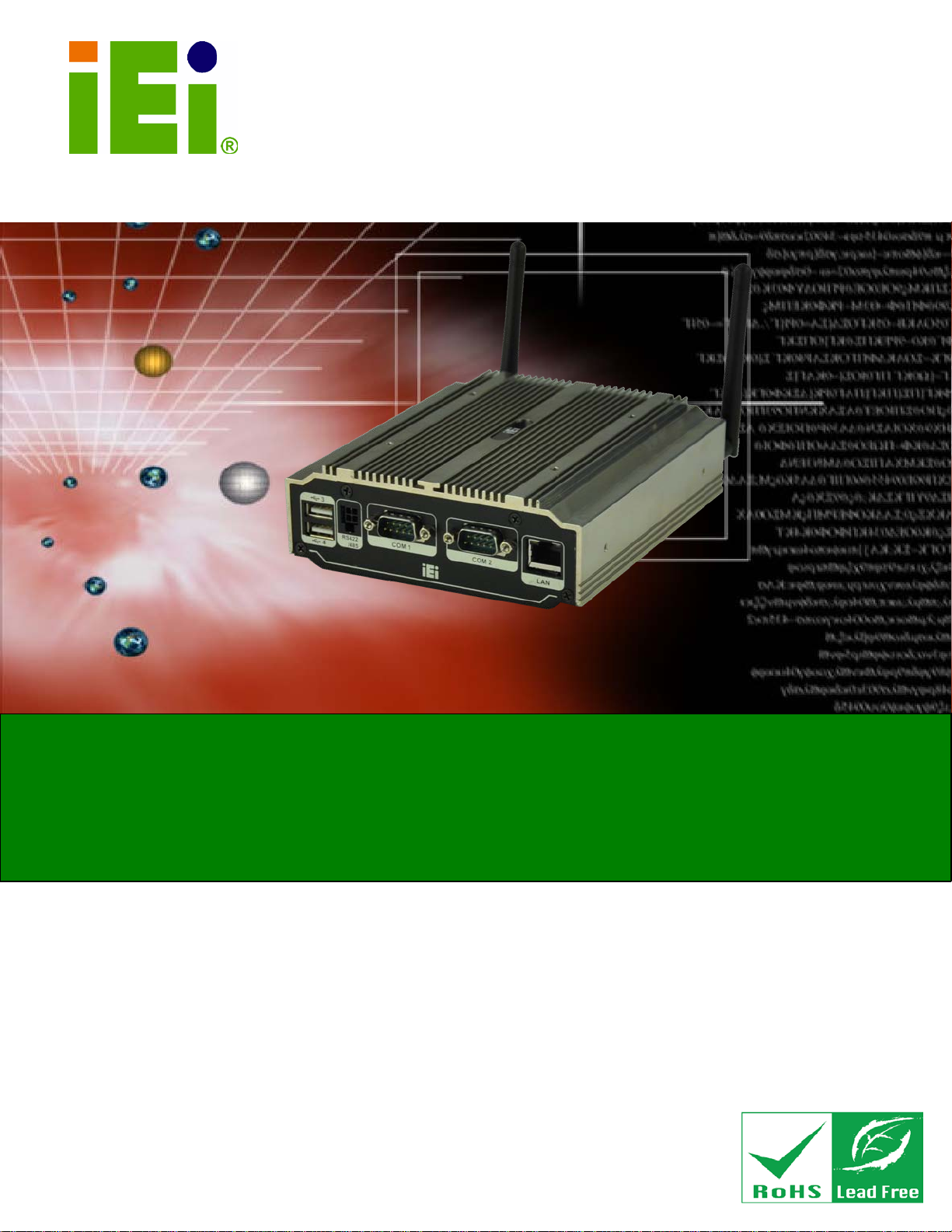
uIBX-210-CV-N2600 Embedded Sys tem
Page i
MODEL:
Fanless Embedded Sys tem with Intel® Atom™ N2600
Rev. 1.01 – 28 Fe brua r y 2013
,
IEI Technolog y Corp.
uIBX-210-CV-N2600 Series
DC 1.6GHz, Intel® NM10 chips et, Pre-installed 2GB DDR3
memory, VGA, HDMI, GbE, Four USB 2. 0,
Three COM and RoHS C ompliant
Us er Manual
Page 2

uIBX-210-CV-N2600 Embedded Sys tem
Page ii
Date Version Changes
28 February 2013 1.01 Update Section 2.3: Packing List
27 December 2012 1.00 Initial release
Revision
Page 3

uIBX-210-CV-N2600 Embedded Sys tem
Page iii
Copyright
COP YRIGHT NOTICE
The information in this document is subject to change without prior notice in order to
improve reliabilit y, design a nd functi on and d oes not r epresent a com mitm ent on the part
of the manufacturer.
In no event will the manufacturer be liable for direct, indirect, special, incidental, or
consequential damages arising out of the use or inability to use the product or
documentation, even if advised of the possibility of such damages.
This document contains proprietary information protected by copyright. All rights are
reserved. No part of this manual may be reproduced by any mechanica l, electronic, or
other means in any form without prior written permission of the manufacturer.
TRADEMARKS
All registered tradem ark s and produc t nam es ment ioned here in are us ed for identif icatio n
purposes only and m ay be trademarks and/or registe red trademarks of their respect ive
owners.
Page 4

uIBX-210-CV-N2600 Embedded Sys tem
Page iv
Ta ble of Con tents
1 INTRODUCTION .......................................................................................................... 1
1.1 OVERVIEW .................................................................................................................. 2
1.2 MODEL VARIATIONS ................................................................................................... 2
1.3 FEATURES ................................................................................................................... 3
1.4 TECHNICAL SPECIFICATIONS ...................................................................................... 3
1.5 FRONT PANEL ............................................................................................................. 5
1.6 REAR PANEL ............................................................................................................... 5
1.7 DIMENSIONS ............................................................................................................... 7
2 UNPACKING ................................................................................................................. 8
2.1 ANTI-STATIC PRECAUTIONS ........................................................................................ 9
2.2 UNPACKING PRECAUTIONS ......................................................................................... 9
2.3 PACKING LIST ........................................................................................................... 10
3 INSTALLATION .......................................................................................................... 11
3.1 INSTALLATION PRECAUTIONS ................................................................................... 12
3.2 INST ALLATION AND CONFIGURATION STEPS ............................................................. 12
3.3 WI-FI ANTENNA INSTALLATION (WI-FI MODEL ONLY) ............................................ 12
3.4 AT/ATX MODE SELECTION ...................................................................................... 13
3.4.1 AT Power Mode ................................................................................................ 14
3.4.2 ATX Power Mode ............................................................................................. 14
3.5 RESET THE SYSTEM .................................................................................................. 14
3.6 POWERING ON THE SYSTEM ..................................................................................... 15
3.7 MOUNT THE SYSTEM ................................................................................................ 15
3.7.1 Wall Mount ....................................................................................................... 16
3.7.2 VESA mount 75 ................................................................................................ 18
3.7.3 VESA mount 100 .............................................................................................. 21
3.8 EXTERNAL PERIPHERAL INTERFACE CONNECTORS ................................................... 23
3.8.1 Audio Connection ............................................................................................. 25
3.8.2 HDMI Device Connection ................................................................................ 26
3.8.3 LAN Connection ............................................................................................... 27
Page 5

uIBX-210-CV-N2600 Embedded Sys tem
Page v
3.8.4 RS-232Serial Port Connection ......................................................................... 28
3.8.5 RS-422/485 Serial Port Connection ................................................................. 29
3.8.6 USB Device Connection ................................................................................... 30
3.8.7 VGA Monitor Connection ................................................................................ 31
4 SYSTEM MOTHERBOARD ..................................................................................... 32
4.1 OVERVIEW ................................................................................................................ 33
4.1.1 Layout .............................................................................................................. 33
4.2 INTERNAL PERIPHERAL CONNECTORS ...................................................................... 33
4.2.1 Battery Connector (BAT1) ............................................................................... 34
4.2.2 BIOS Programming Connector (SPI1) ............................................................ 34
4.2.3 Debug port Connector (DEBUGCN1) ............................................................. 34
4.2.4 HDD LED Connector (HDDLED1) ................................................................. 35
4.2.5 JSATA Connector (JSATA2) ............................................................................. 35
4.2.6 Power LED Connector (PWRLED1) ............................................................... 35
4.2.7 USB 2.0 Connector (USB4_5) ......................................................................... 36
4.2.8 SATA Connector (S_ATA1) ............................................................................... 36
4.2.9 SATA Power Connector (CN1) ......................................................................... 36
4.3 EXTERNAL INTERFACE PANEL CONNECTORS ............................................................ 37
4.3.1 Audio Jack (JAUDIO1) .................................................................................... 37
4.3.2 Ethernet Connector (LAN1) ............................................................................. 37
4.3.3 HDMI Connector (HDMI1) ............................................................................. 38
4.3.4 Power Connector (DC_JACK1) ...................................................................... 38
4.3.5 RS-232 Serial Ports (COM1, COM2) .............................................................. 38
4.3.6 RS-422/485 Serial Port (COM3) ..................................................................... 39
4.3.7 USB 2.0 Connectors (USB0_1) ........................................................................ 39
4.3.8 USB 2.0 Connector (USB23) ........................................................................... 39
4.3.9 VGA Connector (VGA1) ................................................................................... 39
4.4 JUMPER SETTINGS .................................................................................................... 40
4.4.1 AT/ATX Mode Select Jumper (J_AUTOPWR1) ............................................... 40
5 SYSTEM MAINTENANCE ....................................................................................... 41
5.1 SYSTEM MAINTENANCE INTRODUCTION .................................................................. 42
5.2 ANTI-STATIC PRECAUTIONS ...................................................................................... 42
5.3 TURN OFF THE POWER .............................................................................................. 43
Page 6

uIBX-210-CV-N2600 Embedded Sys tem
Page vi
5.4 REPLACING COMPONENTS ........................................................................................ 43
5.4.1 Hard Disk Drive (HDD) Replacement ............................................................. 43
5.4.2 Memory Module Replacement ......................................................................... 46
5.4.3 WLAN Card Replacement ................................................................................ 47
6 BIOS .............................................................................................................................. 50
6.1 INTRODUCTION ......................................................................................................... 51
6.1.1 Starting Setup ................................................................................................... 51
6.1.2 Using Setup ...................................................................................................... 51
6.1.3 Getting Help ..................................................................................................... 52
6.1.4 Unable to Reboot after Configuration Changes .............................................. 52
6.1.5 BIOS Menu Bar ................................................................................................ 52
6.2 MAIN ........................................................................................................................ 53
6.3 ADVANCED ............................................................................................................... 54
6.3.1 ACPI Configuration ......................................................................................... 54
6.3.2 RTC Wake Settings ........................................................................................... 55
6.3.3 CPU Configuration .......................................................................................... 57
6.3.4 SATA Configuration ......................................................................................... 58
6.3.5 USB Configuration ........................................................................................... 59
6.3.6 F81866 Super IO Configuration ...................................................................... 60
6.3.6.1 Serial Port n Configuration ....................................................................... 61
6.3.7 F81866 H/W Monitor ....................................................................................... 64
6.3.8 Serial Port Console Redirection ...................................................................... 65
6.3.8.1 Console Redirection Settings .................................................................... 66
6.4 IEI FEATURE ............................................................................................................. 68
6.5 CHIPSET ................................................................................................................... 69
6.5.1 Host Bridge Configuration .............................................................................. 70
6.5.1.1 Intel IGD Configuration ............................................................................ 70
6.5.2 Southbridge Configuration .............................................................................. 71
6.6 BOOT ........................................................................................................................ 72
6.7 SECURITY ................................................................................................................. 75
6.7.1 HDD Security Configuration ........................................................................... 76
6.8 SAVE & EXIT ............................................................................................................ 77
7 SOFTWARE DRIVERS .............................................................................................. 79
Page 7

uIBX-210-CV-N2600 Embedded Sys tem
Page vii
7.1 AVAILABLE SOFTWARE DRIVERS .............................................................................. 80
7.2 STARTING THE DRIVER PROGRAM ............................................................................ 80
7.3 CHIPSET DRIVER INSTALLATION ............................................................................... 81
7.4 GRAPHIC DRIVER INSTALLATION .............................................................................. 85
7.5 LAN DRIVER INSTALLATION .................................................................................... 88
7.6 AUDIO DRIVER INSTALLATION ................................................................................. 92
A SAFETY PRECAUTIONS ......................................................................................... 95
A.1 SAFETY PRECAUTIONS ............................................................................................ 96
A.1.1 General Safety Precautions ............................................................................. 96
A.1.2 Anti-static Precautions .................................................................................... 97
A.1.3 Product Disposal ............................................................................................. 98
A.2 MAINTENANCE AND CLEANING PRECAUTIONS ........................................................ 98
A.2.1 Maintenance and Cleaning .............................................................................. 98
A.2.2 Cleaning T ools ................................................................................................. 99
B BIOS MENU OPTIONS ........................................................................................... 100
C ONE KEY RECOVERY ........................................................................................... 103
C.1 ONE KEY RECOVERY INTRODUCTION .................................................................... 104
C.1.1 System Requirement ...................................................................................... 105
C.1.2 Supported Operating System ......................................................................... 106
C.2 SETUP PROCEDURE FOR WINDOWS ........................................................................ 107
C.2.1 Hardware and BIOS Setup ............................................................................ 108
C.2.2 Create Partitions ........................................................................................... 108
C.2.3 Install Operating System, Drivers and Applications ...................................... 112
C.2.4 Building the Recovery Partition ..................................................................... 113
C.2.5 Create Factory Default Image ....................................................................... 115
C.3 AUTO RECOVERY SETUP PROCEDURE .................................................................... 120
C.4 SETUP PROCEDURE FOR LINUX .............................................................................. 125
C.5 RECOVERY TOOL FUNCTIONS ................................................................................ 128
C.5.1 Factory Restore ............................................................................................. 129
C.5.2 Backup System ............................................................................................... 130
C.5.3 Restore Your Last Backup .............................................................................. 131
C.5.4 Manual .......................................................................................................... 132
C.6 RESTORE SYSTEMS FROM A LINUX SERVER THROUGH LAN .................................. 133
Page 8

uIBX-210-CV-N2600 Embedded Sys tem
Page viii
C.6.1 Configure DHCP Server Settings .................................................................. 134
C.6.2 Configure TFTP Settings ............................................................................... 135
C.6.3 Configure One Key Recovery Server Settings ............................................... 136
C.6.4 Start the DHCP, TFTP and HTTP ................................................................. 137
C.6.5 Create Shared Directory ................................................................................ 137
C.6.6 Setup a Client System for Auto Recovery ...................................................... 138
C.7 OTHER INFORMATION ............................................................................................ 141
C.7.1 Using AHCI Mode or ALi M5283 / VIA VT6421A Controller ...................... 141
C.7.2 System Memory Requirement ........................................................................ 143
D WATCHDOG TIMER .............................................................................................. 144
E HAZARDOUS MATERIALS DISCLOSURE ....................................................... 147
E.1 HAZARDOUS MATERIALS DISCLOSURE TABLE FOR IPB PRODUCTS CERTIFIED AS
ROHS COMPLIANT UNDER 2002/95/EC WITHOUT MERCURY ..................................... 148
Page 9

uIBX-210-CV-N2600 Embedded Sys tem
Page ix
List of Figures
Figure 1-1: uIBX-210-CV-N2600 ..................................................................................................... 2
Figure 1-2: uIBX-210-CV-N2600 Front Panel
Figure 1-3: uIBX-210-CV-N2600 Rear Panel
Figure 1-4: Physical Dimensions (mm)
Figure 3-1: Wi-Fi Antenna Installation
Figure 3-2: AT/ATX Switch Location
Figure 3-3: Reset Button Location
Figure 3-4: Power Button Location
Figure 3-5: Wall-mounting Bracket
Figure 3-6: Chassis Support Screws
Figure 3-7: Secure the uIBX-210-CV-N2600
Figure 3–8: Panel PC (VESA 75 mm)
Figure 3–9: Mount Kit Installation
Figure 3–10: Slide the System
Figure 3–11: Mount Kit Screws
Figure 3–12: Stand Installation
Figure 3–13: Panel PC ( VESA 100 mm)
Figure 3–14: 100 mm to 75 mm Adapter
................................................................................ 5
................................................................................. 6
........................................................................................ 7
........................................................................................13
...........................................................................................13
..............................................................................................15
.............................................................................................15
.............................................................................................16
..........................................................................................17
...............................................................................18
..........................................................................................18
...............................................................................................19
.....................................................................................................19
...................................................................................................20
...................................................................................................20
......................................................................................21
....................................................................................21
Figure 3–15: Mount Kit Installation
Figure 3–16: Slide the System
Figure 3–17: Mount Kit Screws
Figure 3–18: Stand Installation
Figure 3-19: Peripheral Connectors (Front Panel)
Figure 3-20: Peripheral Connectors (Rear Panel)
Figure 3-21: Audio Connector
Figure 3-22: HDMI Connection
Figure 3-23: LAN Connection
Figure 3-24: DB-9 Serial Port Connector
Figure 3-25: RS-422/485 Cable
Figure 3-26: USB Device Connection
.............................................................................................22
.....................................................................................................22
...................................................................................................23
...................................................................................................23
....................................................................24
.....................................................................25
.....................................................................................................26
....................................................................................................27
......................................................................................................28
....................................................................................29
....................................................................................................30
.........................................................................................30
Page 10

uIBX-210-CV-N2600 Embedded Sys tem
Page x
Figure 3-27: VGA Connector .......................................................................................................31
Figure 4-1: System Motherboard
Figure 5-1: Retention Screws Removal
Figure 5-2: HDD Bracket Retention Screws
Figure 5-3: HDD Bracket
Figure 5-4: HDD Retention Screws
Figure 5-5: Remove the old HDD
Figure 5-6: uIBX-210-CV-N2600 SO-DIMM Socket Location
Figure 5-7: DDR3 SO-DIMM Module Installation
Figure 5-8: uIBX-210-CV-N2600 SO-DIMM Socket Location
Figure 5-9: Removing the Antennas
Figure 5-10: Releasing the WLAN Card
Figure 5-11: Removing the WLAN card
Figure 7-1: Drivers
Figure 7-2: Chipset Driver Screen
Figure 7-3: Chipset Driver Welcome Screen
Figure 7-4: Chipset Driver License Agreement
Figure 7-5: Chipset Driver Read Me File
................................................................................................33
......................................................................................43
...............................................................................44
..............................................................................................................44
.............................................................................................45
.................................................................................................45
.....................................................46
........................................................................47
.....................................................48
...........................................................................................48
......................................................................................49
......................................................................................49
........................................................................................................................81
...............................................................................................82
..............................................................................82
.........................................................................83
....................................................................................84
Figure 7-6: Chipset Driver Installation Finish Screen
Figure 7-7: VGA Driver Welcome Screen
Figure 7-8: VGA Driver License Agreement
Figure 7-9: VGA Driver Read Me File
Figure 7-10: VGA Driver Setup Operations
Figure 7-11: VGA Driver Installation Finish Screen
Figure 7-12: Windows Control Panel
Figure 7-13: System Control Panel
Figure 7-14: Device Manager List
Figure 7-15: Update Driver Software Window
Figure 7-16: Locate Driver Files
Figure 7-17: LAN Driver Installation
Figure 7-18: LAN Driver Installatio n Complete
Figure 7-19: Audio Driver Welcome Screen
Figure 7-20: Audio Driver Installation
Figure 7-21: Audio Driver Installation Complete
Figure C-1: IEI One Key Recovery Tool Menu
...............................................................84
...................................................................................85
...............................................................................86
..........................................................................................86
................................................................................87
..................................................................88
..........................................................................................88
.............................................................................................89
...............................................................................................90
...........................................................................91
..................................................................................................91
...........................................................................................92
..........................................................................92
...............................................................................93
.........................................................................................94
.......................................................................94
.........................................................................104
Page 11

uIBX-210-CV-N2600 Embedded Sys tem
Page xi
Figure C-2: Launching the Recovery Tool ...............................................................................109
Figure C-3: Recovery Tool Setup Menu
Figure C-4: Command Prompt
Figure C-5: Partition Creation Commands
Figure C-6: Launching the Recovery Tool
Figure C-7: Manual Recovery Environment fo r Windows
Figure C-8: Building the Recovery Partition
Figure C-9: Press Any Key to Continue
Figure C-10: Press F3 to Boot into Recovery Mode
Figure C-11: Recovery Tool Menu
Figure C-12: About Symantec Ghost Window
Figure C-13: Symantec Ghost Path
Figure C-14: Select a Local Source Drive
Figure C-15: Select a Source Partition from Basic Drive
Figure C-16: File Name to Copy Image to
Figure C-17: Compress Image
Figure C-18: Image Creation Confirmation
Figure C-19: Image Creation Complete
...................................................................................109
..................................................................................................110
...............................................................................111
...............................................................................113
......................................................113
............................................................................114
...................................................................................114
................................................................115
............................................................................................115
.........................................................................116
..........................................................................................116
................................................................................117
.......................................................117
................................................................................118
...................................................................................................118
..............................................................................119
....................................................................................119
Figure C-20: Image Creation Complete
Figure C-21: Press Any Key to Continue
Figure C-22: Auto Recovery Utility
Figure C-23: Launching the Recovery Tool
Figure C-24: Auto Recovery Environment for Windows
Figure C-25: Building the Auto Recovery Partition
Figure C-26: Factory Default Image Confirmation
Figure C-27: Image Creation Complete
Figure C-28: Press any key to continue
Figure C-29: Partitions for Linux
Figure C-30: Manual Recovery Environment for Linux
Figure C-31: Access menu.lst in Linux (Text Mode)
Figure C-32: Recovery Tool Menu
Figure C-33: Recovery Tool Main Menu
Figure C-34: Restore Factory Default
Figure C-35: Recovery Complete Window
Figure C-36: Backup System
....................................................................................119
.................................................................................120
...........................................................................................121
.............................................................................121
........................................................121
.................................................................122
..................................................................122
....................................................................................123
...................................................................................123
...............................................................................................125
..........................................................126
...............................................................127
............................................................................................127
...................................................................................128
.......................................................................................129
...............................................................................130
.....................................................................................................130
Page 12

uIBX-210-CV-N2600 Embedded Sys tem
Page xii
Figure C-37: System Backup Complete Window ....................................................................131
Figure C-38: Restore Backup
Figure C-39: Restore System Backup Complete Window
Figure C-40: Symantec Ghost Window
....................................................................................................131
......................................................132
....................................................................................132
Page 13

uIBX-210-CV-N2600 Embedded Sys tem
Page xiii
List of Tables
Table 1-1: Model Variations ........................................................................................................... 2
Table 1-2: Technical Specifications
Table 2-1: Package List Contents
Table 4-1: Peripheral Interface Connectors
Table 4-2: Battery Connector Pinouts (BAT1)
Table 4-3: BIOS Programming Connector Pinouts (SPI1)
Table 4-4: Debug port Connector Pinouts (DEBUGCN1)
Table 4-5: HDD LED Connector P inouts (HDDLED1)
Table 4-6: JSATA Connector Pinouts (JSATA2)
Table 4-7: Power LED Connector Pinouts (PWRLED1)
Table 4-8: USB 2.0 Connector Pinouts (USB4_5)
Table 4-9: SATA Connector Pino u ts (S_ATA1)
Table 4-10: SATA Power Connector Pinouts (CN1)
Table 4-11: Rear Panel Connectors
Table 4-12: Audio Jack Pinouts (JAUDIO1)
Table 4-13: Ethernet Connector Pinouts (LAN1)
Table 4-14: HDMI Connector (HDMI1) Pinouts
Table 4-15: Power Connector Pinouts (DC_JACK1)
.............................................................................................. 5
...............................................................................................10
...............................................................................34
...........................................................................34
........................................................34
..........................................................35
................................................................35
.......................................................................35
............................................................35
......................................................................36
.........................................................................36
..................................................................36
............................................................................................37
...............................................................................37
.......................................................................38
...........................................................................38
.................................................................38
Table 4-16: RS-232 Serial Ports Pinouts (COM1, COM2)
Table 4-17: RS-422/485 Serial Port Pinouts (COM3)
Table 4-18: USB 2.0 Connectors Pinouts (USB0_1)
Table 4-19: USB 2.0 Connector Pinouts (USB2_3)
Table 4-20: VGA Connector Pinouts (VGA1)
Table 4-21: Jumper
Table 4-22: AT/ATX Mode Select Jumper Settings (J_AUTOPWR1)
Table 6-1: BIOS Navigation Keys
..........................................................39
.................................................................39
..................................................................39
....................................................................39
.............................................................................40
.......................................................................................................................40
.......................................40
................................................................................................52
Page 14

uIBX-210-CV-N2600 Embedded Sys tem
Page 1
Chapter
1
1 Introduction
Page 15

uIBX-210-CV-N2600 Embedded Sys tem
Page 2
1.1 Overview
Figure 1-1: uIBX-210-CV-N2600
The uIBX-210-CV-N2600 embedded system is a fanless system with one VGA port and
one HDMI port for dua l display. It accepts a Intel® N2600 1.6GHz dual-c ore processor
and supports one 204-pin 800 MHz dual-chan nel D D R3 SDR AM SO-DIMM module up to
2 GB. The uIBX-210-CV-N2600 supports a 2.5” SATA HDD with up to 3 Gb/s data transfer
rate. Three serial ports and four external USB 2.0 ports ensure simplified connectivity to a
variety of external peripheral devices.
1.2 Model Variations
The model variations of the uIBX-210-CV-N2600 series are listed below.
Models CPU Wireless
uIBX-210-CV-N2600/2GB-R10 Intel® Atom™ N2600 N/A
UIBX-210W -CV-N2600/2GB-R10 Intel® Atom™ N2600 2T2R 8 02.11b/g/n
Table 1-1: Model Variations
Page 16

uIBX-210-CV-N2600 Embedded Sys tem
Page 3
1.3 Features
The uIBX-210-CV-N2600 features are listed below:
Slim and compact embedded system design with Intel® 3rd Gen Atom N2600
dual-core processor , Supports DDR3 memory (System Max. 2GB)
12V only single voltage design, supports AT/ATX power mode selection
Flexible VGA and HDMI with dual-display support
Support PCIe Mini card slot
Fully I/O with four USB, one VGA, one HDMI, three COM and audio
1.4 Technical Specifications
The uIBX-210-CV-N2600 technical specifications are listed in Table 1-2.
Chassis
Form Fac tor
Color
Dimensions
Chassis Construction
Motherboard
CPU
Chipset
BIOS
Memo ry
Chipset Graphics Engine
Expansion
Audio
Storage
uIBX
Silver
146.6mm x 132mm x 45.2mm
Aluminum Alloy , ABS
Intel® N2600 1.6GHz dual-core processor,
Intel® NM10
UEFI BIOS
2GB DDR3 800MHz (N2600 supports up to 2GB)
Intel® GMA 3600, 400 MHz core speed for N2600
1 x PCIe Mini card slot
Realtek ALC662 HD Audio codec
SATA
1 x 2.5'' SATA HDD
Page 17

uIBX-210-CV-N2600 Embedded Sys tem
Page 4
1 x VGA
2 x USB port
System Function
Dis play Output
Ethernet
Super I/O
Indicators
Front I/Os
Rear I/Os
Support HDMI, VGA for dual independent display
Display 1: Analog CRT up to 1920x1200 for Cedarview-D and
Cedarview-M, support CRT hot plug
Display 2: HDMI up to 1920 x 1200
1 x RJ-45 LAN by Realtek RTL8111E GbE
Fintek F81866
HDD LED / Power LED indicator
1 x HDMI
1 x Mic-in
1 x Line-out,
2 x USB port
2 x RS-232 (COM 1, COM 2)
Interior Expansions
Button & Switch
Power
Power Supply
Power Consumption
Reliability
Watchdog Timer
1 x RS-422/485 (COM 3)
1 x RJ-45 LAN
1 x PCIe Mini slot (reserved for Wi-Fi)
Reset switch
AT/ATX switch
Power Button
AT/ATX support
DC IN:12V/5A
Locking type DC-in jack on board (rear side)
+12V @ 1.57A (Intel R Atom N2600 dual Core 1.6GHz , DDR3 800
2GB memory)
Software programmable 1~255 sec. system reset
Page 18

uIBX-210-CV-N2600 Embedded Sys tem
Page 5
Hardware Monitor
Operating Temperature
Mounting
EMC/Safety
Supported OS
Table 1-2: Technical Specifications
Fintek F81865
0°C ~ 50°C with air flow
VESA 75
CE, FCC class A
Microsoft® WES7E
Microsoft® Windows® XP Embedded
Microsoft® CE 6.0
1.5 Front Panel
The front panel of the uIBX-210-CV-N2600 has the following features (Figure 1-2):
2 x RS-232 serial port connectors (COM1, COM2)
1 x RS-422/485 serial port connector (COM3)
1 x RJ-45 LAN connector
2 x USB 2.0 connectors
Figure 1-2: uIBX-210-CV-N2600 Front Panel
1.6 Rear Panel
The rear panel of the uIBX-210-CV-N2600 has the following features (Figure 1-3):
2 x Antenna connectors
Page 19

uIBX-210-CV-N2600 Embedded Sys tem
Page 6
1 x AT/ATX Switch
1 x HDD LED
1 x HDMI port
1 x Line out
1 x Mic
1 x Power button
1 x Power LED
1 x Reset button
2 x USB 2.0 connectors
1 x 12 V DC IN
1 x VGA port
Figure 1-3: uIBX-210-CV-N2600 Rear Pan e l
Page 20

uIBX-210-CV-N2600 Embedded Sys tem
Page 7
1.7 Dimensions
The physical dimensions are shown below:
Figure 1-4: Physical Dimensions (mm)
Page 21

uIBX-210-CV-N2600 Embedded Sys tem
Page 8
Chapter
2
2 Unpacking
Page 22

uIBX-210-CV-N2600 Embedded Sys tem
Page 9
2.1 Anti-static Precautions
WARNING:
Failure to take ESD precautions during installation may result in
permanent damage to the uIBX-210-CV-N2600 and severe injury to
the user.
Electrostatic discharge (ESD) can cause serious damage to electronic components,
including the uIBX-210-CV-N2600. Dry climates are especially susc eptible to ESD. It is
therefore critical that whenever the uIBX-210-CV-N2600 or any other electrical component
is handled, the following anti-static precautions are strictly adhered to.
Wear an anti-static wristband: Wearing a simple anti-static wristband can
help to prevent ESD from damaging the board.
Self-grounding: Before handling the board, touch any grounded conducting
material. During the time the board is handled, frequently touch any
conducting materials that are connected to the ground.
Use an anti-static pad: When configuring the uIBX-210-CV-N2600, place it
on an antic-static pad. This reduces the possibility of ESD damaging the
uIBX-210-CV-N2600.
2.2 Unpacking Precautions
When the uIBX-210-CV-N2600 is unpacked, please do the following:
Follow the anti-static precautions outlined in Section 2.1.
Make sure the packing box is facing upwards so the uIBX-210-CV-N2600
does not fall out of the box.
Make sure all the components shown in Section 2.3 are present.
Page 23

uIBX-210-CV-N2600 Embedded Sys tem
Page 10
2.3 Packing Lis t
NOTE:
If som e of the components listed in the checklist below are missing,
please do not proceed with the installation. Contact the IEI resel ler or
vendor you purchased the uIBX-210-CV-N2600 from or contac t an IEI
sales representative directly. To contact an IEI sales representative,
please send an email to
The uIBX-210-CV-N2600 is shipped with the following components:
Quantity Item and Part Number Imag e
1 uIBX-210-CV-N2600
1 1 x Adaptor 12V/5A
1 1 x Screw set
1 Utility CD
sales@iei.com.tw.
1 One Key Recovery CD
Table 2-1: Package List Contents
 Loading...