

Page 1

IEI Technology Corp.
User Manual
TANK-GM45 Embedded System
MODEL:
TANK-GM45
Wide Range Temperature Fanless Embedded System
with VGA, Gigabit Ethernet, Four USB,
RS-232/422/485, RoHS Compliant
Rev. 1.01 – 29 August 2011
Page i
Page 2
TANK-GM45 Embedded System
Revision
Date Version Changes
29 August 2011 1.01 Changed the supported processor from Intel® Core2
Duo P8600 to Intel® Core2 Duo P8400
15 June, 2010 1.00 Initial release
Page ii
Page 3

TANK-GM45 Embedded System
COPYRIGHT NOTICE
The information in this document is subject to change without prior notice in order to
improve reliability, design and function and does not represent a commitment on the part
of the manufacturer.
In no event will the manufacturer be liable for direct, indirect, special, incidental, or
consequential damages arising out of the use or inability to use the product or
documentation, even if advised of the possibility of such damages.
This document contains proprietary information protected by copyright. All rights are
Copyright
reserved. No part of this manual may be reproduced by any mechanical, electronic, or
other means in any form without prior written permission of the manufacturer.
TRADEMARKS
All registered trademarks and product names mentioned herein are used for identification
purposes only and may be trademarks and/or registered trademarks of their respective
owners.
Page iii
Page 4

TANK-GM45 Embedded System
Table of Contents
1 INTRODUCTION........................................................................................................... 1
1.1 OVERVIEW.................................................................................................................. 2
1.2 MODEL VARIATIONS ................................................................................................... 2
1.3 BENEFITS ................................................................................................................... 2
1.4 FEATURES................................................................................................................... 3
1.5 TECHNICAL SPECIFICATIONS ...................................................................................... 3
1.6 CONNECTOR PANEL.................................................................................................... 5
1.7 DIMENSIONS............................................................................................................... 6
2 UNPACKING .................................................................................................................. 7
2.1 ANTI-STATIC PRECAUTIONS........................................................................................ 8
2.2 UNPACKING PRECAUTIONS......................................................................................... 8
2.3 UNPACKING CHECKLIST ............................................................................................. 9
3 INSTALLATION........................................................................................................... 10
3.1 INSTALLATION PRECAUTIONS....................................................................................11
3.2 HARD DISK DRIVE (HDD) INSTALLATION.................................................................11
3.3 JUMPER SETTINGS .................................................................................................... 14
3.3.1 COM3 RS-422/485 Setup................................................................................. 15
3.4 EXTERNAL PERIPHERAL INTERFACE CONNECTORS................................................... 15
3.4.1 LAN Connectors............................................................................................... 16
3.4.2 Keyboard/Mouse Connector............................................................................ 18
3.4.3 Power Input...................................................................................................... 18
3.4.4 Remote Control Connector.............................................................................. 19
3.4.5 RS-232 Serial Port Connector......................................................................... 20
3.4.6 RS-422/485 Serial Port Connector.................................................................. 21
3.4.7 USB Connector ................................................................................................ 22
3.4.8 VGA Connector................................................................................................ 23
3.4.9 AT/ATX Power Mode Selection........................................................................ 25
4 BIOS.............................................................................................................................. 26
Page iv
Page 5

TANK-GM45 Embedded System
4.1 INTRODUCTION......................................................................................................... 27
4.1.1 Starting Setup................................................................................................... 27
4.1.2 Using Setup...................................................................................................... 27
4.1.3 Getting Help..................................................................................................... 28
4.1.4 Unable to Reboot After Configuration Changes.............................................. 28
4.1.5 BIOS Menu Bar................................................................................................ 28
4.2 MAIN........................................................................................................................ 29
4.3 ADVANCED............................................................................................................... 30
4.3.1 CPU Configuration.......................................................................................... 31
4.3.2 IDE Configuration........................................................................................... 32
4.3.2.1 SATA Channel........................................................................................... 34
4.3.3 Super IO Configuration ................................................................................... 38
4.3.4 Hardware Health Configuration...................................................................... 39
4.3.5 AHCI Configuration......................................................................................... 40
4.3.5.1 AHCI Port n.............................................................................................. 41
4.3.6 Remote Access Configuration.......................................................................... 42
4.3.7 USB Configuration........................................................................................... 45
4.3.8 Power Configuration........................................................................................ 46
4.4 PCI/PNP................................................................................................................... 47
4.5 BOOT........................................................................................................................ 49
4.5.1 Boot Settings Configuration............................................................................. 50
4.5.2 Boot Device Priority........................................................................................ 52
4.5.3 Hard Disk Drives............................................................................................. 53
4.6 SECURITY................................................................................................................. 53
4.7 CHIPSET ................................................................................................................... 54
4.7.1 Northbridge Configuration.............................................................................. 55
4.7.2 Southbridge Configuration .............................................................................. 56
4.8 EXIT......................................................................................................................... 57
A ONE KEY RECOVERY................................................................................................ 59
A.1 ONE KEY RECOVERY INTRODUCTION...................................................................... 60
A.1.1 System Requirement......................................................................................... 61
A.1.2 Supported Operating System........................................................................... 62
A.2 SETUP PROCEDURE FOR WINDOWS.......................................................................... 63
A.2.1 Hardware and BIOS Setup .............................................................................. 63
Page v
Page 6

A.2.2 Create Partitions............................................................................................. 64
A.2.3 Install Operating System, Drivers and Applications....................................... 67
A.2.4 Build-up Recovery Partition............................................................................ 68
A.2.5 Create Factory Default Image......................................................................... 70
A.3 SETUP PROCEDURE FOR LINUX................................................................................ 75
A.4 RECOVERY TOOL FUNCTIONS .................................................................................. 78
A.4.1 Factory Restore............................................................................................... 80
A.4.2 Backup System................................................................................................. 81
A.4.3 Restore Your Last Backup................................................................................ 82
A.4.4 Manual............................................................................................................. 83
A.5 OTHER INFORMATION.............................................................................................. 84
A.5.1 Using AHCI Mode or ALi M5283 / VIA VT6421A Controller......................... 84
A.5.2 System Memory Requirement .......................................................................... 86
B SAFETY PRECAUTIONS........................................................................................... 87
TANK-GM45 Embedded System
B.1 SAFETY PRECAUTIONS............................................................................................. 88
B.1.1 General Safety Precautions............................................................................. 88
B.1.2 Anti-static Precautions.................................................................................... 89
B.2 MAINTENANCE AND CLEANING PRECAUTIONS........................................................ 89
B.2.1 Maintenance and Cleaning.............................................................................. 89
B.2.2 Cleaning Tools................................................................................................. 90
C HAZARDOUS MATERIALS DISCLOSURE............................................................. 91
C.1 HAZARDOUS MATERIALS DISCLOSURE TABLE FOR IPB PRODUCTS CERTIFIED AS
ROHS COMPLIANT UNDER 2002/95/EC WITHOUT MERCURY ....................................... 92
Page vi
Page 7

TANK-GM45 Embedded System
List of Figures
Figure 1-1: TANK-GM45 .................................................................................................................2
Figure 1-2: TANK-GM45 Peripheral Connectors .........................................................................5
Figure 1-3: Physical Dimensions (millimeters)............................................................................6
Figure 3-1: Bottom Panel Retention Screws (Rear Panel) .......................................................11
Figure 3-2: Bottom Panel Retention Screws (Bottom Panel)...................................................12
Figure 3-3: Open the Bottom Panel ............................................................................................12
Figure 3-4: HDD Bracket Retention Screws...............................................................................13
Figure 3-5: HDD Retention Screws.............................................................................................13
Figure 3–6: HDD Installation........................................................................................................14
Figure 3-7: Peripheral Connectors (Rear)..................................................................................16
Figure 3-8: LAN Connection........................................................................................................17
Figure 3-9: RJ-45 Ethernet Connector........................................................................................17
Figure 3-10: PS/2 Keyboard/Mouse Connector.........................................................................18
Figure 3-11: Power Input Connector...........................................................................................19
Figure 3-12: Remote Control Terminal Block Pinout Location................................................19
Figure 3-13: Serial Device Connector.........................................................................................20
Figure 3-14: Serial Port Pinout Location....................................................................................21
Figure 3-15: Serial Port Pinout Location....................................................................................22
Figure 3-16: USB Device Connection.........................................................................................23
Figure 3-17: VGA Connector .......................................................................................................24
Figure 3-18: VGA Connector .......................................................................................................24
Figure 3-19: AT/ATX Switch.........................................................................................................25
Figure A-1: IEI One Key Recovery Tool Menu...........................................................................60
Figure A-2: Launching the Recovery Tool.................................................................................64
Figure A-3: Recovery Tool Setup Menu .....................................................................................65
Figure A-4: Command Mode........................................................................................................65
Figure A-5: Partition Creation Commands.................................................................................66
Figure A-6: Launching the Recovery Tool.................................................................................68
Figure A-7: System Configuration for Windows .......................................................................68
Figure A-8: Build-up Recovery Partition....................................................................................69
Page vii
Page 8

Figure A-9: Press any key to continue.......................................................................................69
Figure A-10: Press F3 to Boot into Recovery Mode..................................................................70
Figure A-11: Recovery Tool Menu ..............................................................................................70
Figure A-12: About Symantec Ghost Window...........................................................................71
Figure A-13: Symantec Ghost Path ............................................................................................71
Figure A-14: Select a Local Source Drive ..................................................................................72
Figure A-15: Select a Source Partition from Basic Drive .........................................................72
Figure A-16: File Name to Copy Image to ..................................................................................73
Figure A-17: Compress Image.....................................................................................................73
Figure A-18: Image Creation Confirmation................................................................................74
Figure A-19: Image Creation Process.........................................................................................74
Figure A-20: Image Creation Complete......................................................................................74
Figure A-21: Press Any Key to Continue...................................................................................75
Figure A-22: Partitions for Linux.................................................................................................76
TANK-GM45 Embedded System
Figure A-23: System Configuration for Linux............................................................................77
Figure A-24: Access menu.lst in Linux (Text Mode).................................................................77
Figure A-25: Recovery Tool Menu ..............................................................................................78
Figure A-26: Recovery Tool Main Menu.....................................................................................79
Figure A-27: Restore Factory Default.........................................................................................80
Figure A-28: Recovery Complete Window.................................................................................80
Figure A-29: Backup System.......................................................................................................81
Figure A-30: System Backup Complete Window ......................................................................81
Figure A-31: Restore Backup......................................................................................................82
Figure A-32: Restore System Backup Complete Window........................................................82
Figure A-33: Symantec Ghost Window ......................................................................................83
Page viii
Page 9

TANK-GM45 Embedded System
List of Tables
Table 1-1: TANK-GM45 Model Variations.....................................................................................2
Table 1-2: Technical Specifications..............................................................................................4
Table 2-1: Package List Contents.................................................................................................9
Table 3-1: COM3 RS-422/485 Setup............................................................................................15
Table 3-2: COM3 RS-422/485 Setup............................................................................................15
Table 3-3: COM3 RS-422/485 Setup............................................................................................15
Table 3-4: LAN Pinouts ................................................................................................................17
Table 3-5: RJ-45 Ethernet Connector LEDs...............................................................................18
Table 3-6: Power Input Pinouts...................................................................................................19
Table 3-7: Remote Control Terminal Block Pinouts..................................................................19
Table 3-8: COM1 Serial Port Pinouts..........................................................................................21
Table 3-9: RS-422 Pinouts ...........................................................................................................21
Table 3-10: RS-485 Pinouts .........................................................................................................22
Table 3-11: USB Port Pinouts......................................................................................................23
Table 3-12: VGA Connector Pinouts...........................................................................................25
Table 4-1: BIOS Navigation Keys................................................................................................28
Page ix
Page 10

Page 11

TANK-GM45 Embedded System
Chapter
1
1 Introduction
Page 1
Page 12
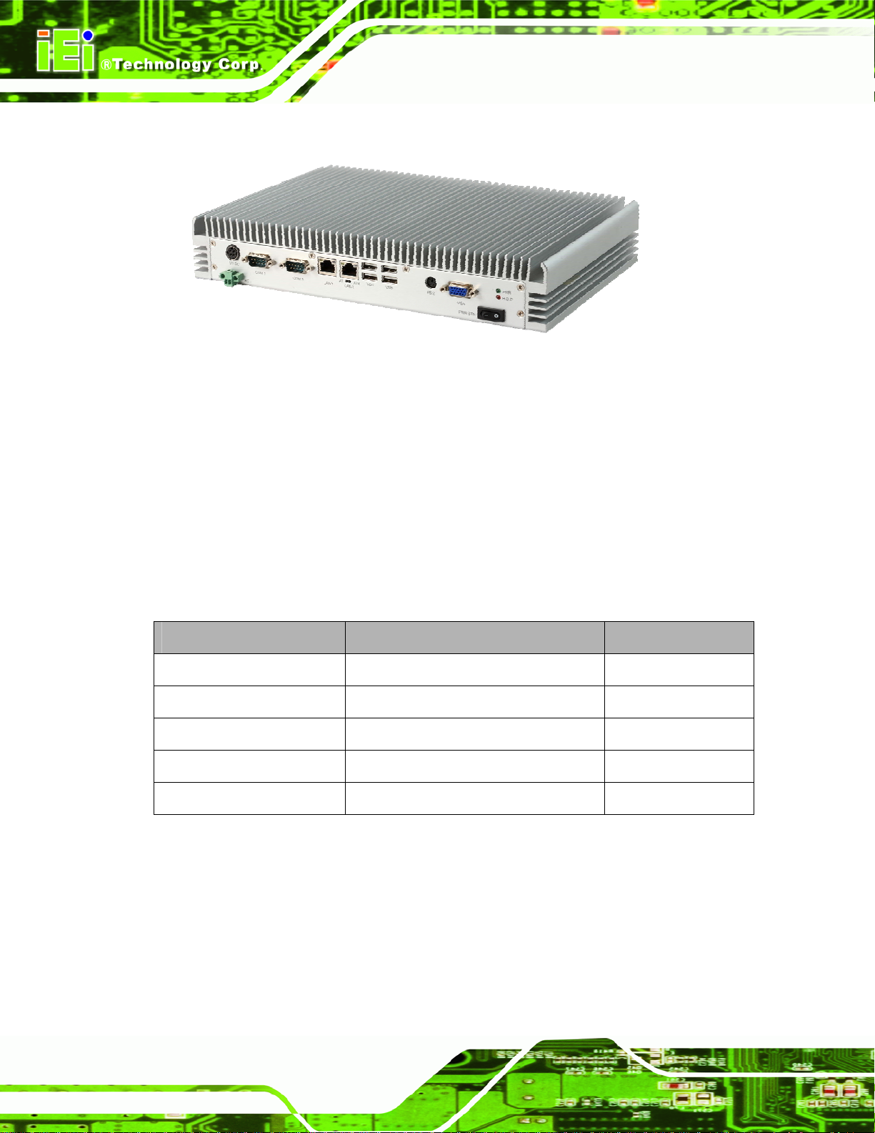
1.1 Overview
Figure 1-1: TANK-GM45
The TANK-GM45 Series embedded system is a fanless system for wide range
temperature environments. It is powered by the Intel® 45nm Core™2 Duo processor,
uses the Intel® GM45 chipset and has 2.0 GB of DDR2 memory. The TANK-GM45B in
this series is preinstalled with a 32 GB SATA Solid State Disk (SSD) with up to 3Gb/s data
TANK-GM45 Embedded System
transfer rate.
1.2 Model Variations
The model variations of the TANK-GM45 Series are listed below.
Model No. CPU Preinstalled SSD
TANK-GM45A-R10/P8400
TANK-GM45A-R10/CM575 2.0 GHz Intel® Celeron 575 --
TANK-GM45B-T9400
TANK-GM45B-P8400
TANK-GM45B-CM575 2.0 GHz Intel® Celeron 575 32 GB SATA SSD
Table 1-1: TANK-GM45 Model Variations
2.26 GHz Intel® Core2 Duo P8400
2.53 GHz Intel® Core2 Duo T9400
2.26 GHz Intel® Core2 Duo P8400
--
32 GB SATA SSD
32 GB SATA SSD
1.3 Benefits
Page 2
Some of the TANK-GM45 benefits include:
Wide range storage temperature for various environments.
Less downtime from overheating because there are not fans to fail
Page 13
TANK-GM45 Embedded System
Cost savings with low power consumption
1.4 Features
The TANK-GM45 features are listed below:
Intel® 45nm Core™2 Duo processor
2.0 GB of DDR2 SDRAM SO-DIMM preinstalled
One GPIO block terminal for remote control
Two Gigabit Ethernet ports
Four USB 2.0 ports
One RS-232 isolated serial port
One RS-422/485 isolated serial port
One VGA port
AT/ATX power mode supported
RoHS compliant
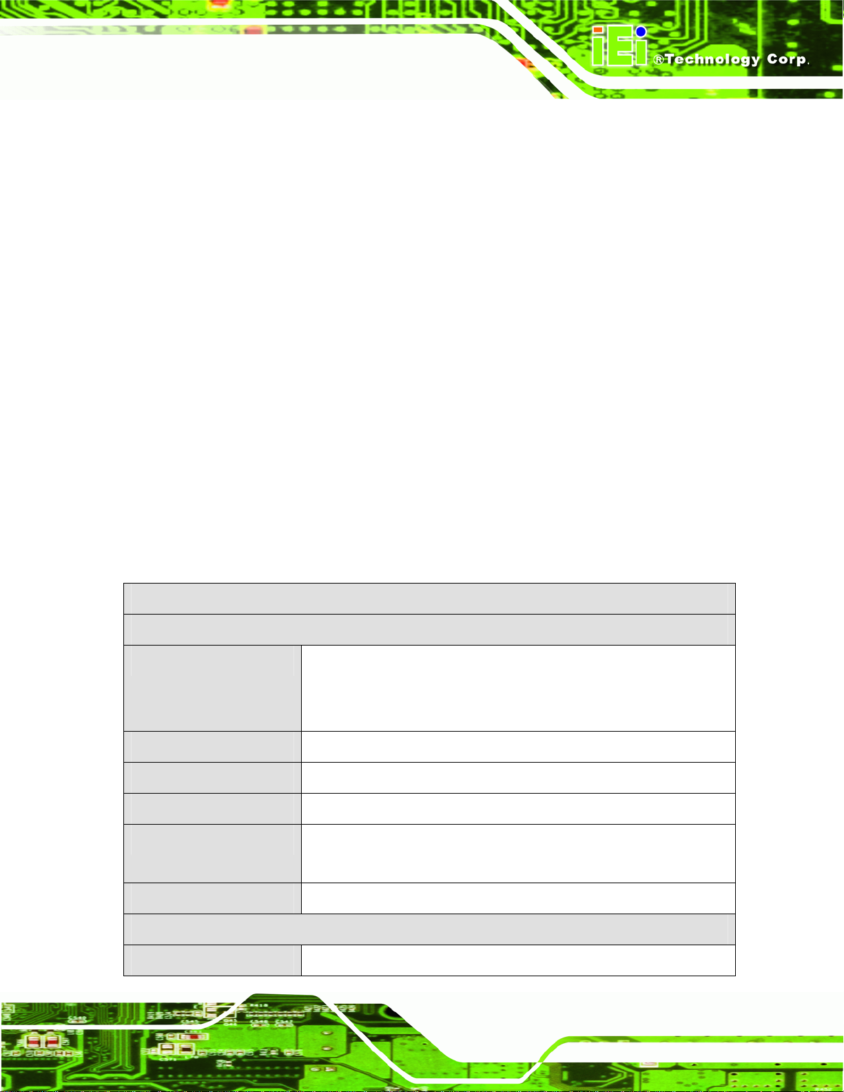
1.5 Technical Specifications
The TANK-GM45 technical specifications are listed in Table 1-2.
Specifications
System
Supported CPU
Memory
Real-time Clock
Watchdog Timer
Ethernet Controller
2.53 GHz Intel® Core2 Duo T9400 CPU,
2.26 GHz Intel® Core2 Duo P8400 CPU or
2.0 GHz Intel® Celeron 575 CPU
2.0 GB of DDR2 SO-DIMM preinstalled
Battery backup RTC
Software programmable supports 1~255 sec. system reset
One Intel® 82574L PCIe GbE Controller
One Intel® WG82567LM GbE PHY
Supported OS
I/O and Indicators
Ethernet
Windows® XP or Linux
2 x 10/100/1000 Mb/s
Page 3
Page 14
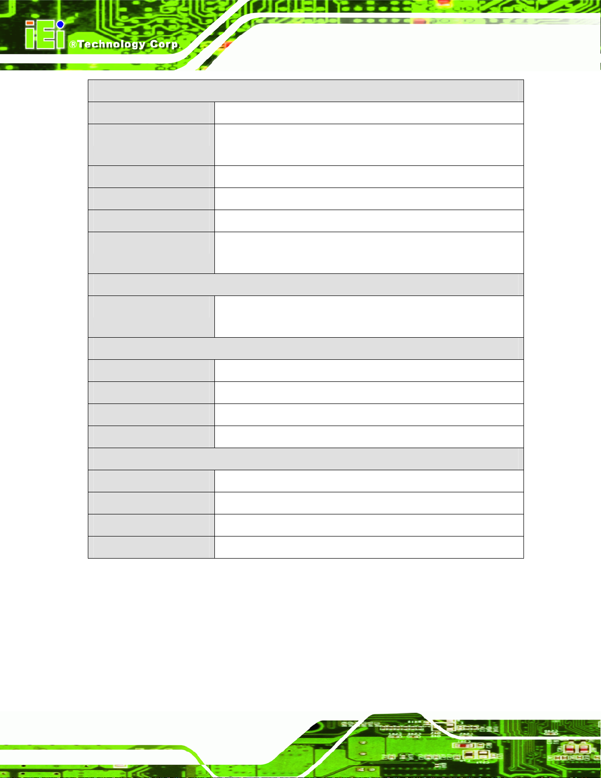
Specifications
TANK-GM45 Embedded System
Keyboard/Mouse
Serial Ports
USB Interfaces
VGA
GPIO
LED Indicator
Storage
SDD
Power
Power Supply
Power Consumption
One PS/2 keyboard/mouse connector
1 x RS-232 (isolated)
1 x RS-422/485 (isolated)
4 x USB 2.0 ports
One VGA port
One 2-pin terminal block for remote control
One power LED (green)
One HDD LED (red)
Support one 2.5” SATA HDD
(TANK-GM45B is preinstalled with one 32 GB SATA 3Gb/s SSD)
+12 V DC
45 W
Power Switch
Power Mode
Environmental and Mechanical
Operating Temperature
Storage Temperature
Color
Physical Dimensions
Table 1-2: Technical Specifications
One power switch
AT or ATX power mode (selectable by AT/ATX switch)
-20°C~70°C
-25°C~75°C
Silver
310 mm x 200 mm x 55 mm (W x D x H)
Page 4
Page 15
TANK-GM45 Embedded System
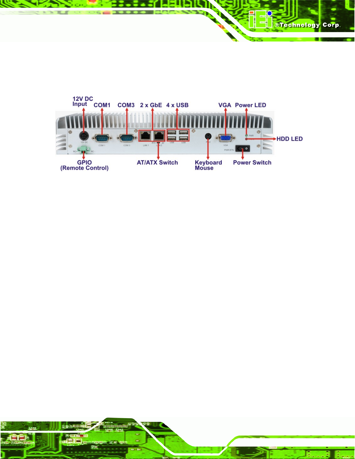
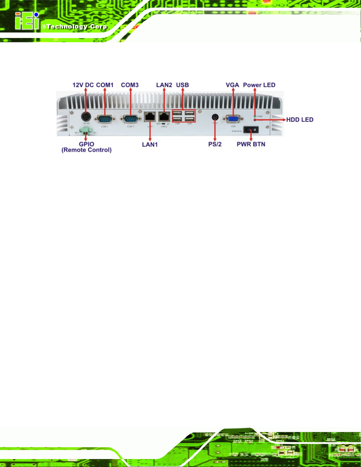
1.6 Connector Panel
All external peripheral interface connectors are located on the front panel of the
TANK-GM45 . The peripheral interface connectors are shown in
Figure 1-2: TANK-GM45 Peripheral Connectors
Connectors and buttons on the rear panel include the following.
1 x 12 V DC power input
1 x Power switch
1 x VGA output
Figure 1-2.
1 x RS-232 port isolated serial port
1 x RS-422/485 isolated serial port
4 x USB ports
2 x Gigabit Ethernet ports
1 x GPIO terminal block for remote control
1 x PS/2 keyboard/mouse connector
1 x Power LED
1 x HDD LED
1 x AT/ATX power switch
Page 5
Page 16
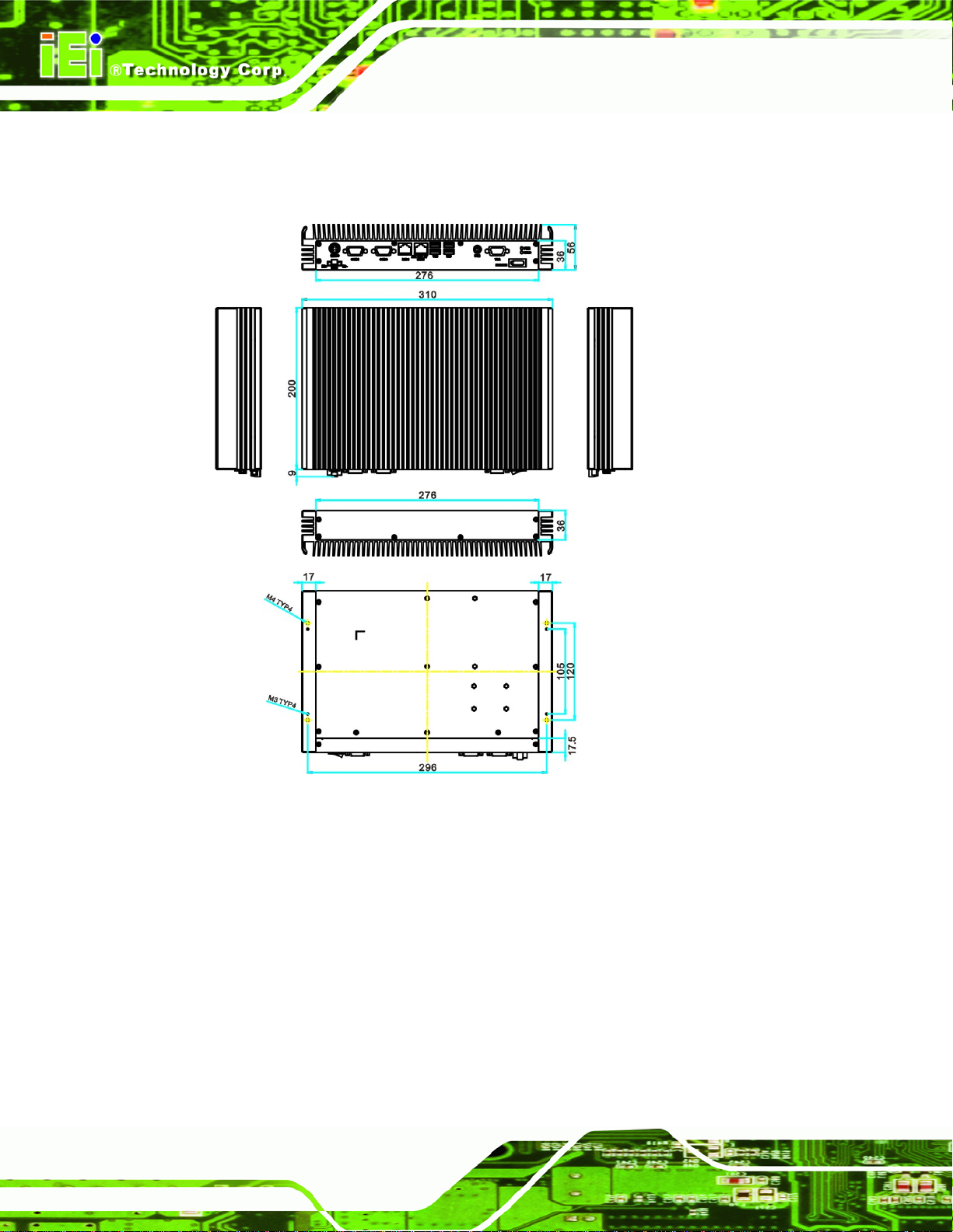
1.7 Dimensions
The physical dimensions are shown below:
TANK-GM45 Embedded System
Page 6
Figure 1-3: Physical Dimensions (millimeters)
Page 17

TANK-GM45 Embedded System
Chapter
2
2 Unpacking
Page 7
Page 18

2.1 Anti-static Precautions
WARNING:
Failure to take ESD precautions during installation may result in
permanent damage to the TANK-GM45 and severe injury to the user.
Electrostatic discharge (ESD) can cause serious damage to electronic components,
including the TANK-GM45. Dry climates are especially susceptible to ESD. It is therefore
critical that whenever the TANK-GM45 or any other electrical component is handled, the
following anti-static precautions are strictly adhered to.
Wear an anti-static wristband: Wearing a simple anti-static wristband can
help to prevent ESD from damaging the board.
TANK-GM45 Embedded System
Self-grounding: Before handling the board touch any grounded conducting
material. During the time the board is handled, frequently touch any
conducting materials that are connected to the ground.
Use an anti-static pad: When configuring the TANK-GM45, place it on an
antic-static pad. This reduces the possibility of ESD damaging the
TANK-G M45 .
2.2 Unpacking Precautions
When the TANK-GM45 is unpacked, please do the following:
Follow the anti-static precautions outlined in Section
Make sure the packing box is facing upwards so the TANK-GM45 does not fall
out of the box.
Make sure all the components shown in Section
2.1.
2.3 are present.
Page 8
Page 19
TANK-GM45 Embedded System
2.3 Unpacking Checklist
NOTE:
If some of the components listed in the checklist below are missing,
please do not proceed with the installation. Contact the IEI reseller or
vendor you purchased the TANK-GM45 from or contact an IEI sales
representative directly. To contact an IEI sales representative, please
send an email to
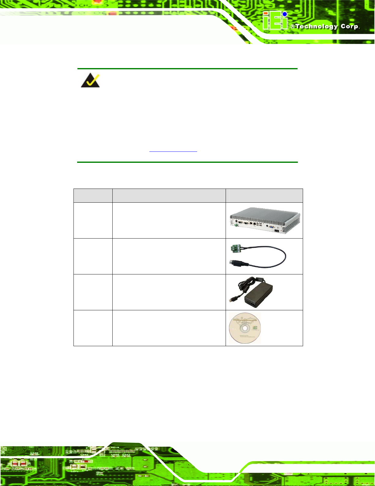
The TANK-GM45 is shipped with the following components:
Quantity Item and Part Number Image
1 TANK-GM45
1 DC input cable (with terminal block)
(TANK-GM45A only)
1 Power adapter (TANK-GM45B only)
1 User manual and driver CD
sales@iei.com.tw.
Table 2-1: Package List Contents
Page 9
Page 20

TANK-GM45 Embedded System
Chapter
3
3 Installation
Page 10
Page 21

TANK-GM45 Embedded System
3.1 Installation Precautions
During installation, be aware of the precautions below:
Read the user manual: The user manual provides a complete description of
the TANK-GM45, installation instructions and configuration options.
DANGER! Disconnect Power: Power to the TANK-GM45 must be
disconnected during the installation process, or before any attempt is made to
access the rear panel. Electric shock and personal injury might occur if the
rear panel of the TANK-GM45 is opened while the power cord is still
connected to an electrical outlet.
Qualified Personnel: The TANK-GM45 must be installed and operated only
by trained and qualified personnel. Maintenance, upgrades, or repairs may
only be carried out by qualified personnel who are familiar with the associated
dangers.
Air Circulation: Make sure there is sufficient air circulation when installing the
TANK-GM45. The TANK-GM45’s cooling vents must not be obstructed by any
objects. Blocking the vents can cause overheating of the TANK-GM45. Leave
at least 5 cm of clearance around the TANK-GM45 to prevent overheating.
Grounding: The TANK-GM45 should be properly grounded. The voltage
feeds must not be overloaded. Adjust the cabling and provide external
overcharge protection per the electrical values indicated on the label attached
to the back of the TANK-GM45.
3.2 Hard Disk Drive (HDD) Installation
To install the hard drive, please follow the steps below:
Step 1: Remove the bottom panel by removing 15 retention screws from the rear panel
Figure 3-1) and the bottom panel (Figure 3-2).
(
Figure 3-1: Bottom Panel Retention Screws (Rear Panel)
Page 11
Page 22
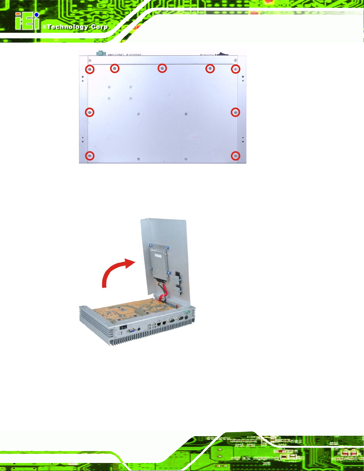
Figure 3-2: Bottom Panel Retention Screws (Bottom Panel)
Step 2: To prevent the internal SATA cable from damage, please open the bottom panel
TANK-GM45 Embedded System
as shown below.
Figure 3-3: Open the Bottom Panel
Page 12
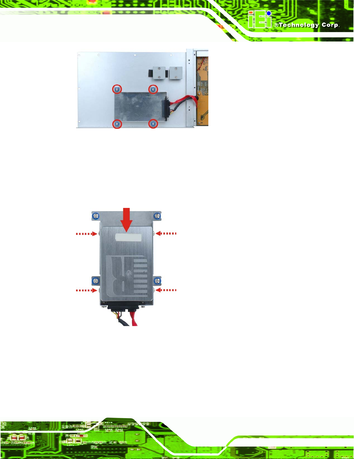
Step 3: Remove the four HDD bracket retention screws (
brackets out of the TANK-GM45.
Figure 3-4) and lift the HDD
Page 23
TANK-GM45 Embedded System
Figure 3-4: HDD Bracket Retention Screws
Step 4: Attach the HDD bracket to the HDD. Slide the HDD to connect the HDD to the
SATA connector. Secure the HDD with the HDD bracket by four retention screws
(
Figure 3-5).
Figure 3-5: HDD Retention Screws
Page 13
Page 24
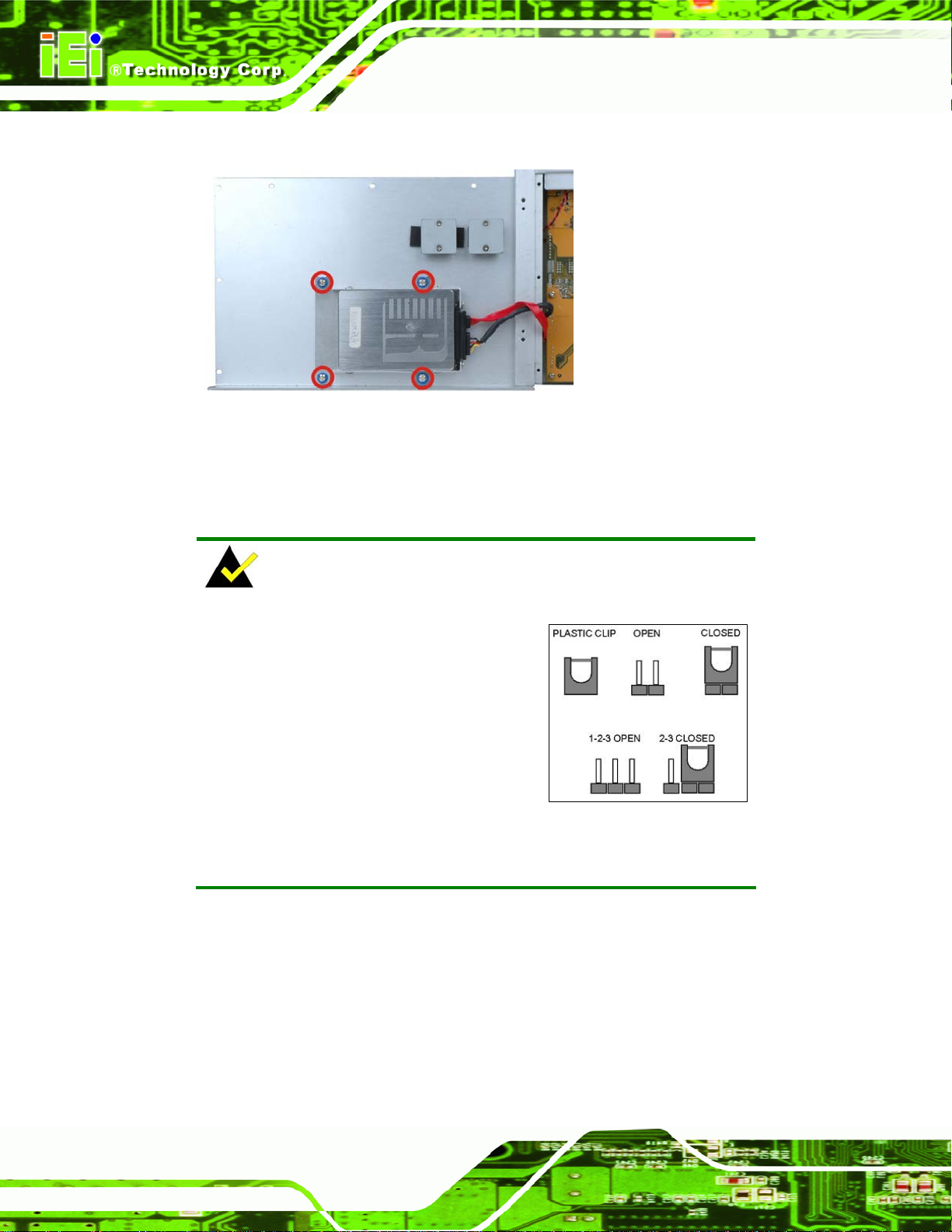
Step 5: Install the HDD bracket in the same position it was before.
Figure 3–6: HDD Installation
Step 6: Reinstall the bottom panel. Step 0:
3.3 Jumper Settings
TANK-GM45 Embedded System
NOTE:
A jumper is a metal bridge used to close
an electrical circuit. It consists of two or
three metal pins and a small metal clip
(often protected by a plastic cover) that
slides over the pins to connect them. To
CLOSE/SHORT a jumper means
connecting the pins of the jumper with
the plastic clip and to OPEN a jumper means removing the plastic clip
from a jumper.
To access jumper, please remove the bottom panel (refer to Section 3.2), 12
motherboard retention screws and six front panel retention screws. The motherboard
jumper is listed below.
COM3 RS-422/485 selection
Page 14
Page 25
TANK-GM45 Embedded System
3.3.1 COM3 RS-422/485 Setup
Jumper Label:
Jumper Type:
Jumper Settings:
This serial port can be set to use RS-422 or RS-485 communication methods. Set all the
jumpers to the same settings.
J5 Description
2-3, 5-6, 8-9, 11-12 RS-422/485 (Default)
Table 3-1: COM3 RS-422/485 Setup
J5, J9 and J10
Pin headers
Table 3-1, Table 3-2 and Table 3-3
See
J9 Description
3-4 RS-422 (Default)
5-6 RS-485
Table 3-2: COM3 RS-422/485 Setup
J10 Description
1-3, 2-4 RS-422 (Default)
3-5, 4-6 RS-485
Table 3-3: COM3 RS-422/485 Setup
3.4 External Peripheral Interface Connectors
The TANK-GM45 has the following connectors. Detailed descriptions of the connectors
can be found in the subsections below.
Ethernet
Keyboard/Mouse
Power button
Power input
GPIO for remote control
RS-232
Page 15
Page 26
RS-422/485
USB
TANK-GM45 Embedded System
VGA
Figure 3-7: Peripheral Connectors (Rear)
3.4.1 LAN Connectors
CN Label:
CN Type:
CN Location:
LAN1 and LAN2
RJ-45
Figure 3-7
See
Table 3-4
CN Pinouts:
The LAN connectors allow connection to an external network.
Step 1: Locate the RJ-45 connectors. The locations of the RJ-45 connectors are
shown above.
Step 2: Align the connectors. Align the RJ-45 connector on the LAN cable with one of
the RJ-45 connectors on the TANK-GM45. See
See
Figure 3-8.
Page 16
Page 27
TANK-GM45 Embedded System
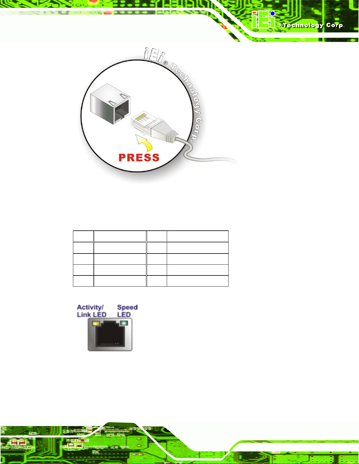
Figure 3-8: LAN Connection
Step 3: Insert the LAN cable RJ-45 connector. Once aligned, gently insert the LAN
cable RJ-45 connector into the on-board RJ-45 connector. Step 0:
Pin Description Pin Description
1 TRD1P0 5 TRD1P2
2 TRD1N0 6 TRD1N2
3. TRD1P1 7 TRD1P3
4. TRD1N1 8 TRD1N3
Table 3-4: LAN Pinouts
Figure 3-9: RJ-45 Ethernet Connector
The RJ-45 Ethernet connector has two status LEDs, one green and one yellow. The green
LED indicates activity on the port and the yellow LED indicates the port is linked. See
Table 3-5.
Page 17
Page 28

Activity/Link LED Speed LED
TANK-GM45 Embedded System
STATUS
Off No link Off 10 Mbps connection
Yellow Linked Green 100 Mbps connection
Blinking TX/RX activity Orange 1 Gbps connection
Table 3-5: RJ-45 Ethernet Connector LEDs
DESCRIPTION STATUS DESCRIPTION
3.4.2 Keyboard/Mouse Connector
CN Label: PS/2
CN Type:
CN Location:
CN Location:
The PS/2 connector connects to a keyboard and a mouse.
PS/2
Figure 3-7
See
Figure 3-10
See
Figure 3-10: PS/2 Keyboard/Mouse Connector
3.4.3 Power Input
CN Label: 12VDC
CN Type:
CN Location:
CN Pinouts:
The power connector connects to the 12 V DC power adapter.
Page 18
4-pin DIN connector
Figure 3-7
See
Figure 3-11
See
Page 29

TANK-GM45 Embedded System
Figure 3-11: Power Input Connector
Pin Description Pin Description
1 +12V 3 +12V
2 GND 4 GND
Table 3-6: Power Input Pinouts
3.4.4 Remote Control Connector
CN Label: GPIO (Remote Control)
CN Type:
CN Location:
CN Pinouts:
The GPIO terminal block connects to a remote control device. Users can control the
system power on/off by inputting high or low voltage into the terminal block.
2-pin terminal block
Figure 3-7
See
Table 3-7 and Figure 3-12
See
Turn off the system: more than 1 V input
Turn on the system: less than 0.5 V input
Pin Description
1 RC+
2 RC-
Table 3-7: Remote Control Terminal Block Pinouts
Figure 3-12: Remote Control Terminal Block Pinout Location
Page 19
Page 30
3.4.5 RS-232 Serial Port Connector
CN Label: COM1
TANK-GM45 Embedded System
CN Type:
CN Location:
CN Pinouts:
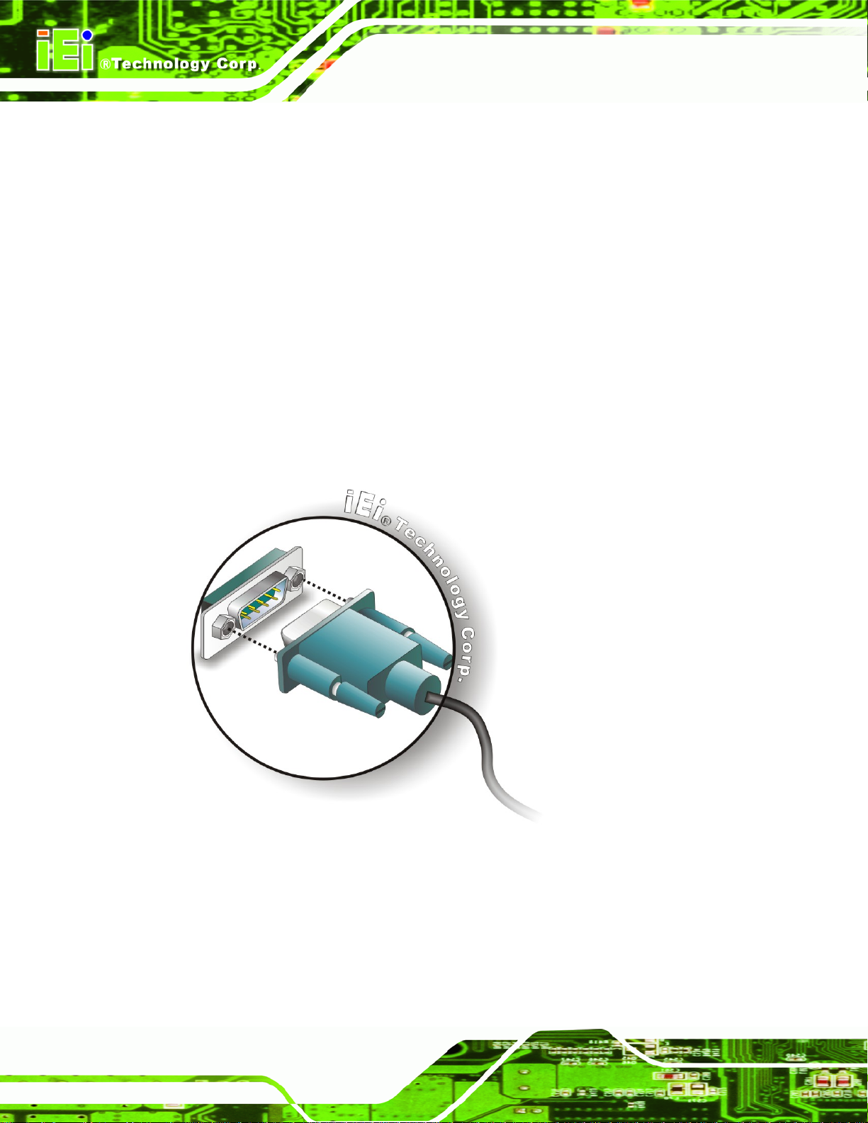
RS-232 serial port devices can be attached to the DB-9 ports on the rear panel.
Step 1: Locate the DB-9 connector. The location of the DB-9 connector is shown in
Figure 3-7.
Step 2: Insert the serial connector. Insert the DB-9 connector of a serial device into
the DB-9 connector on the external peripheral interface. See
DB-9 connectors
Figure 3-7
See
Table 3-8 and Figure 3-14
See
Figure 3-13.
Page 20
Figure 3-13: Serial Device Connector
Step 3: Secure the connector. Secure the serial device connector to the external
interface by tightening the two retention screws on either side of the connector.
Step 0:
Page 31

TANK-GM45 Embedded System
Pin Description Pin Description
1 DCD 6 DSR
2 RX 7 RTS
3 TX 8 CTS
4 DTR 9 RI
5 GND
Table 3-8: COM1 Serial Port Pinouts
Figure 3-14: Serial Port Pinout Location
3.4.6 RS-422/485 Serial Port Connector
CN Label: COM3
CN Type:
CN Location:
CN Pinouts:
DB-9 connectors
Figure 3-7
See
Table 3-9 and Table 3-10
See
RS-422/485 serial port devices can be attached to the DB-9 ports on the rear panel. The
COM3 serial port is a RS-422 serial port by default. To change to RS-485, please refer to
the jumper setting (Section
COM 3 RS-422 Description
Pin 1 TX-
Pin 2 TX+
Pin 6 RX-
Pin 7 RX+
3.3.1).
Table 3-9: RS-422 Pinouts
Page 21
Page 32

COM 3 RS-485 Description
Pin 1 DataPin 2 Data+
TANK-GM45 Embedded System
Table 3-10: RS-485 Pinouts
Figure 3-15: Serial Port Pinout Location
3.4.7 USB Connector
CN Label: USB
CN Type:
CN Location:
CN Pinouts:
USB port
Figure 3-7
See
Table 3-11
See
Page 22
The USB ports are for attaching USB peripheral devices to the system.
Step 1: Located the USB connectors. The locations of the USB connectors are shown
in Chapter 1.
Step 2: Align the connectors. Align the USB device connector with one of the
connectors. See
Figure 3-16.
Page 33

TANK-GM45 Embedded System
Figure 3-16: USB Device Connection
Step 3: Insert the device connector. Once aligned, gently insert the USB device
connector into the on-board connector. Step 0:
Pin Description Pin Description
1 VCC 5 VCC
2 DATA- 6 DATA3 DATA+ 7 DATA+
4 GROUND 8 GROUND
Table 3-11: USB Port Pinouts
3.4.8 VGA Connector
CN Label: VGA
CN Type:
15-pin Female
Figure 3-7
CN Location:
CN Pinouts:
See
Figure 3-18 and Table 3-12
See
Page 23
Page 34

The VGA connector connects to a monitor that accepts VGA video input.
Step 1: Locate the female DB-15 connector. The location of the female DB-15
connector is shown in Chapter 3.
Step 2: Align the VGA connector. Align the male DB-15 connector on the VGA screen
cable with the female DB-15 connector on the external peripheral interface.
Step 3: Insert the VGA connector. Once the connectors are properly aligned with the
insert the male connector from the VGA screen into the female connector on the
TANK-GM45 Embedded System
TANK-GM45. See
Figure 3-17: VGA Connector
Figure 3-17.Step 3:
Page 24
Figure 3-18: VGA Connector
Page 35

TANK-GM45 Embedded System
Pin Description Pin Description
1 RED 2 GREEN
3 BLUE 4 NC
5 GND 6 GND
7 GND 8 GND
9 VCC / NC 10 GND
11 NC 12 DDC DAT
13 HSYNC 14 VSYNC
15 DDCCLK
3.4.9 AT/ATX Power Mode Selection
The TANK-GM45 supports AT and ATX power modes. The setting can be made through
the AT/ATX switch on the external peripheral interface panel as shown below.
Figure 3-19: AT/ATX Switch
Table 3-12: VGA Connector Pinouts
Page 25
Page 36

TANK-GM45 Embedded System
Chapter
4
4 BIOS
Page 26
Page 37

TANK-GM45 Embedded System
4.1 Introduction
The BIOS is programmed onto the BIOS chip. The BIOS setup program allows changes to
certain system settings. This chapter outlines the options that can be changed.
4.1.1 Starting Setup
The AMI BIOS is activated when the computer is turned on. The setup program can be
activated in one of two ways.
1. Press the D
2. Press the D
appears on the screen. 0.
If the message disappears before the D
again.
ELETE key as soon as the system is turned on or
ELETE key when the “Press Del to enter SETUP” message
ELETE key is pressed, restart the computer and try
4.1.2 Using Setup
Use the arrow keys to highlight items, press ENTER to select, use the PageUp and
PageDown keys to change entries, press F1 for help and press E
keys are shown in.
Key Function
Up arrow Move to previous item
Down arrow Move to next item
Left arrow Move to the item on the left hand side
SC to quit. Navigation
Right arrow Move to the item on the right hand side
Esc key Main Menu – Quit and not save changes into CMOS
Status Page Setup Menu and Option Page Setup Menu --
Exit current page and return to Main Menu
Page Up key Increase the numeric value or make changes
Page Dn key Decrease the numeric value or make changes
F1 key General help, only for Status Page Setup Menu and Option
Page Setup Menu
Page 27
Page 38

Key Function
F2 /F3 key Change color from total 16 colors. F2 to select color
F10 key Save all the CMOS changes, only for Main Menu
Table 4-1: BIOS Navigation Keys
4.1.3 Getting Help
When F1 is pressed a small help window describing the appropriate keys to use and the
TANK-GM45 Embedded System
forward.
possible selections for the highlighted item appears. To exit the Help Window press E
the F1 key again.
4.1.4 Unable to Reboot After Configuration Changes
If the computer cannot boot after changes to the system configuration is made, CMOS
defaults. Use the jumper described in Chapter 2.
4.1.5 BIOS Menu Bar
The menu bar on top of the BIOS screen has the following main items:
Main – Changes the basic system configuration.
Advanced – Changes the advanced system settings.
PCIPnP – Changes the advanced PCI/PnP Settings
Boot – Changes the system boot configuration.
Security – Sets User and Supervisor Passwords.
Chipset – Changes the chipset settings.
SC or
Page 28
Exit – Selects exit options and loads default settings
The following sections completely describe the configuration options found in the menu
items at the top of the BIOS screen and listed above.
Page 39

TANK-GM45 Embedded System
4.2 Main
The Main BIOS menu (BIOS Menu 1) appears when the BIOS Setup program is entered.
The Main menu gives an overview of the basic system information.
BIOS SETUP UTILITY
Main Advanced PCIPNP Boot Security Chipset Exit
System Overview
⎯⎯⎯⎯⎯⎯⎯⎯⎯⎯⎯⎯⎯⎯⎯⎯⎯⎯⎯⎯⎯⎯⎯⎯⎯⎯⎯⎯⎯⎯⎯
AMIBIOS
Version :08.00.15
Build Date :01/15/10
ID: :SA11MR13
Processor
Intel(R) Core(TM)2 Duo CPU P8400 @ 2.26GHz
Speed :2400MHz
Count :1
System Memory
Size :2013MB
System Time [16:38:10]
System Time [Fri 02/15/2010]
v02.61 ©Copyright 1985-2006, American Megatrends, Inc.
Use [ENTER], [TAB] or
[SHIFT-TAB] to select a
field.
Use [+] or [-] to
configure system time.
ÅÆ
Select Screen
↑ ↓ Select Item
Enter Go to SubScreen
F1 General Help
F10 Save and Exit
ESC Exit
BIOS Menu 1: Main
System Overview
The System Overvie w lists a brief summary of different system components. The fields in
System Overview cannot be changed. The items shown in the system overview include:
AMI BIOS: Displays auto-detected BIOS information
o Version: Current BIOS version
o Build Date: Date the current BIOS version was made
o ID: Installed BIOS ID
Processor: Displays auto-detected CPU specifications
o Type: Names the currently installed processor
o Speed: Lists the processor speed
o Count: The number of CPUs on the motherboard
System Memory: Displays the auto-detected system memory.
o Size: Lists memory size
Page 29
Page 40

The System Overview field also has two user configurable fields:
System Time [xx:xx:xx]
Use the System Time option to set the system time. Manually enter the hours, minutes
and seconds.
System Date [xx/xx/xx]
Use the System Date option to set the system date. Manually enter the day, month and
year.
4.3 Advanced
Use the Advanced menu (BIOS Menu 2) to configure the CPU and peripheral devices
through the following sub-menus:
TANK-GM45 Embedded System
WARNING!
Setting the wrong values in the sections below may cause the system
to malfunction. Make sure that the settings made are compatible with
the hardware.
CPU Configuration (see Section
IDE Configuration (see Section
Super IO Configuration (see Section
Hardware Health Configuration (see Section
AHCI Configuration (see Section
Remote Access Configuration (see Section
USB Configuration (see Section
Power Configuration (see Section
4.3.1)
4.3.2)
4.3.3)
4.3.4)
4.3.5)
4.3.6)
4.3.7)
4.3.8)
Page 30
Page 41

TANK-GM45 Embedded System
BIOS SETUP UTILITY
Main Advanced PCIPNP Boot Security Chipset Exit
Advanced Settings
⎯⎯⎯⎯⎯⎯⎯⎯⎯⎯⎯⎯⎯⎯⎯⎯⎯⎯⎯⎯⎯⎯⎯⎯⎯⎯⎯⎯⎯⎯⎯
WARNING: Setting wrong values in below sections may cause
system to malfunction
> CPU Configuration
> IDE Configuration
> SuperIO Configuration
> Hardware Health Configuration
> AHCI Configuration
> Remote Access Configuration
> USB Configuration
> Power Configuration
v02.61 ©Copyright 1985-2006, American Megatrends, Inc.
BIOS Menu 2: Advanced
Configure CPU
ÅÆ
Select Screen
↑ ↓ Select Item
Enter Go to SubScreen
F1 General Help
F10 Save and Exit
ESC Exit
4.3.1 CPU Configuration
Use the CPU Configuration menu (BIOS Menu 3) to view detailed CPU specifications
and configure the CPU.
BIOS SETUP UTILITY
Main Advanced PCIPNP Boot Security Chipset Exit
Configure advanced CPU settings
Module Version:3F.15
⎯⎯⎯⎯⎯⎯⎯⎯⎯⎯⎯⎯⎯⎯⎯⎯⎯⎯⎯⎯⎯⎯⎯⎯⎯⎯⎯⎯⎯⎯⎯
Manufacturer: Intel
Intel(R) Core(TM)2 Duo CPU P8400 @ 2.26GHz
Frequency: 2.4GHz
FSB Speed: 1066MHz
Cache L1: 64 KB
Cache L2: 3072 KB
Ratio Actual Value:8.5
v02.61 ©Copyright 1985-2006, American Megatrends, Inc.
BIOS Menu 3: CPU Configuration
ÅÆ
Select Screen
↑ ↓ Select Item
Enter Go to SubScreen
F1 General Help
F10 Save and Exit
ESC Exit
The CPU Configuration menu (BIOS Menu 3) lists the following CPU details:
Manufacturer: Lists the name of the CPU manufacturer
Brand String: Lists the brand name of the CPU being used
Page 31
Page 42

Frequency: Lists the CPU processing speed
FSB Speed: Lists the FSB speed
Cache L1: Lists the CPU L1 cache size
Cache L2: Lists the CPU L2 cache size
TANK-GM45 Embedded System
4.3.2 IDE Configuration
Use the IDE Configuration menu (BIOS Menu 4) to change and/or set the configuration
of the IDE devices installed in the system.
BIOS SETUP UTILITY
Main Advanced PCIPNP Boot Security Chipset Exit
IDE Configuration
⎯⎯⎯⎯⎯⎯⎯⎯⎯⎯⎯⎯⎯⎯⎯⎯⎯⎯⎯⎯⎯⎯⎯⎯⎯⎯⎯⎯⎯⎯⎯
SATA#1 Configuration [Compatible]
Configure SATA#1 as [IDE]
> Primary IDE Master : [Not Detected]
> Primary IDE Slave : [Not Detected]
> Secondary IDE Master : [Not Detected]
> Secondary IDE Slave : [Not Detected]
> Third IDE Master : [Not Detected]
Disabled
Compatible
Enhanced
ÅÆ
Select Screen
↑ ↓ Select Item
Enter Go to SubScreen
F1 General Help
F10 Save and Exit
ESC Exit
v02.61 ©Copyright 1985-2006, American Megatrends, Inc.
BIOS Menu 4: IDE Configuration
Parallel ATA IDE devices
Displays the settings for all the IDE devices. The devices listed below are available.
Primary IDE Master
Primary IDE Slave
Secondary IDE Master
Secondary IDE Slave
Third IDE Master
Page 32
Page 43

TANK-GM45 Embedded System
SATA#1 Configuration [Compatible]
Use the SATA#1 Configuration option to configure the ATA/IDE controller.
Î
Disabled
Î
Compatible DEFAULT
Î
Enhanced
Configure SATA#1 as [IDE]
Use the Configure SATA#1 as option to configure SATA devices as normal IDE devices.
Î
IDE DEFAULT
Configures SATA devices as normal IDE device.
Disables the on-board ATA/IDE controller.
Configures the on-board ATA/IDE controller to be in
compatible mode. In this mode, a SATA channel will
replace one of the IDE channels. This mode supports
up to 4 storage devices.
Configures the on-board ATA/IDE controller to be in
Enhanced mode. In this mode, IDE channels and SATA
channels are separated. This mode supports up to 6
storage devices. Some legacy OS do not support this
mode.
Î
AHCI
Configures SATA devices as AHCI device.
Page 33
Page 44

S
TANK-GM45 Embedded System
4.3.2.1 SATA Channel
Sets the IDE configuration of the SATA channels.
BIOS SETUP UTILITY
Main Advanced PCIPNP Boot Security Chipset Exit
Primary IDE Master
⎯⎯⎯⎯⎯⎯⎯⎯⎯⎯⎯⎯⎯⎯⎯⎯⎯⎯⎯⎯⎯⎯⎯⎯⎯⎯⎯⎯⎯⎯⎯
Device :Not Detected
Type [Auto]
LBA/Large Mode [Auto]
Block (Multi-Sector Transfer) [Auto]
PIO Mode [Auto]
DMA Mode [Auto]
S.M.A.R.T. [Auto]
32Bit Data Transfer [Enabled]
elect the type of device
connected to the system
ÅÆ
Select Screen
↑ ↓ Select Item
Enter Go to SubScreen
F1 General Help
F10 Save and Exit
ESC Exit
v02.61 ©Copyright 1985-2006, American Megatrends, Inc.
BIOS Menu 5: IDE Master and IDE Slave Configuration
Type [Auto]
Use the Type BIOS option select the type of device the AMIBIOS attempts to boot from
after the Power-On Self-Test (POST) is complete.
Î
Not Installed
Î
Auto DEFAULT
Î
CD/DVD
BIOS is prevented from searching for an IDE disk
drive on the specified channel.
The BIOS auto detects the IDE disk drive type
attached to the specified channel. This setting should
be used if an IDE hard disk drive is attached to the
specified channel.
The CD/DVD option specifies that an IDE CD-ROM
drive is attached to the specified IDE channel. The
BIOS does not attempt to search for other types of
IDE disk drives on the specified channel.
Page 34
Page 45

TANK-GM45 Embedded System
Î
ARMD
LBA/Large Mode [Auto]
Use the LBA/Large Mode option to disable or enable BIOS to auto detects LBA (Logical
Block Addressing). LBA is a method of addressing data on a disk drive. In LBA mode, the
maximum drive capacity is 137 GB.
Î
Disabled
Î
Auto DEFAULT
Block (Multi Sector Transfer) [Auto]
This option specifies an ATAPI Removable Media
Device. These include, but are not limited to:
ZIP
LS-120
BIOS is prevented from using the LBA mode control on
the specified channel.
BIOS auto detects the LBA mode control on the specified
channel.
Use the Block (Multi Sector Transfer) to disable or enable BIOS to auto detect if the
device supports multi-sector transfers.
Î
Disabled
Î
Auto DEFAULT
PIO Mode [Auto]
Use the PIO Mode option to select the IDE PIO (Programmable I/O) mode program timing
cycles between the IDE drive and the programmable IDE controller. As the PIO mode
increases, the cycle time decreases.
BIOS is prevented from using Multi-Sector Transfer on the
specified channel. The data to and from the device occurs
one sector at a time.
BIOS auto detects Multi-Sector Transfer support on the
drive on the specified channel. If supported the data
transfer to and from the device occurs multiple sectors at
a time.
Page 35
Page 46

TANK-GM45 Embedded System
Î
Auto DEFAULT
Î
0
Î
1
Î
2
Î
3
Î
4
DMA Mode [Auto]
Use the DMA Mode BIOS selection to adjust the DMA mode options.
BIOS auto detects the PIO mode. Use this value if the IDE disk
drive support cannot be determined.
PIO mode 0 selected with a maximum transfer rate of 3.3 MB/s
PIO mode 1 selected with a maximum transfer rate of 5.2 MB/s
PIO mode 2 selected with a maximum transfer rate of 8.3 MB/s
PIO mode 3 selected with a maximum transfer rate of 11.1 MB/s
PIO mode 4 selected with a maximum transfer rate of 16.6 MB/s
(This setting generally works with all hard disk drives
manufactured after 1999. For other disk drives, such as IDE
CD-ROM drives, check the specifications of the drive.)
Î
Auto DEFAULT
Î
SWDMA0
Î
SWDMA1
Î
SWDMA2
Î
MWDMA0
Î
MWDMA1
Î
MWDMA2
BIOS auto detects the DMA mode. Use this value if the IDE
disk drive support cannot be determined.
Single Word DMA mode 0 selected with a maximum data
transfer rate of 2.1 MB/s
Single Word DMA mode 1 selected with a maximum data
transfer rate of 4.2 MB/s
Single Word DMA mode 2 selected with a maximum data
transfer rate of 8.3 MB/s
Multi Word DMA mode 0 selected with a maximum data
transfer rate of 4.2 MB/s
Multi Word DMA mode 1 selected with a maximum data
transfer rate of 13.3 MB/s
Multi Word DMA mode 2 selected with a maximum data
transfer rate of 16.6 MB/s
Page 36
Î
UDMA0
Ultra DMA mode 0 selected with a maximum data transfer
rate of 16.6 MB/s
Page 47

TANK-GM45 Embedded System
Î
UDMA1
Î
UDMA2
Î
UDMA3
Î
UDMA4
Î
UDMA5
S.M.A.R.T [Auto]
Ultra DMA mode 1 selected with a maximum data transfer
rate of 25 MB/s
Ultra DMA mode 2 selected with a maximum data transfer
rate of 33.3 MB/s
Ultra DMA mode 3 selected with a maximum data transfer
rate of 44 MB/s (To use this mode, it is required that an
80-conductor ATA cable is used.)
Ultra DMA mode 4 selected with a maximum data transfer
rate of 66.6 MB/s (To use this mode, it is required that an
80-conductor ATA cable is used.)
Ultra DMA mode 5 selected with a maximum data transfer
rate of 99.9 MB/s (To use this mode, it is required that an
80-conductor ATA cable is used.)
Use the S.M.A.R.T option to auto-detect, disable or enable Self-Monitoring Analysis and
Reporting Technology (SMART) on the drive on the specified channel. S.M.A.R.T predicts
impending drive failures. The S.M.A.R.T BIOS option enables or disables this function.
Î
Auto DEFAULT
Î
Disabled
Î
Enabled
32Bit Data Transfer [Ena bled]
Use the 32Bit Data Transfer BIOS option to enables or disable 32-bit data transfers.
Î
Disabled
Î
Enabled DEFAULT
BIOS auto detects HDD SMART support.
Prevents BIOS from using the HDD SMART feature.
Allows BIOS to use the HDD SMART feature
Prevents the BIOS from using 32-bit data transfers.
Allows BIOS to use 32-bit data transfers on supported
hard disk drives.
Page 37
Page 48

TANK-GM45 Embedded System
4.3.3 Super IO Configuration
Use the Super IO Configuration menu (BIOS Menu 6) to set or change the
configurations for the FDD controllers, parallel ports and serial ports.
BIOS SETUP UTILITY
Main Advanced PCIPNP Boot Security Chipset Exit
Configure Super I/O Chipset
⎯⎯⎯⎯⎯⎯⎯⎯⎯⎯⎯⎯⎯⎯⎯⎯⎯⎯⎯⎯⎯⎯⎯⎯⎯⎯⎯⎯⎯⎯⎯
Serial Port1 Address [3F8/IRQ4]
Serial Port3 Address [3E8]
Serial Port3 IRQ [10]
Select RS232 or RS422/RS485 [RS422/485]
Allows BIOS to select
Serial Port Base
Addresses
ÅÆ
Select Screen
↑ ↓ Select Item
Enter Go to SubScreen
F1 General Help
F10 Save and Exit
ESC Exit
v02.61 ©Copyright 1985-2006, American Megatrends, Inc.
BIOS Menu 6: Super IO Configuration
Serial Port1 Address [3F8/IRQ4]
Use the Serial Port1 Address option to select the Serial Port 1 base address.
Î
Disabled
Î
3F8/IRQ4 DEFAULT
Î
2F8/IRQ3
Î
3E8/IRQ4
Î
2E8/IRQ3
No base address is assigned to Serial Port 1
Serial Port 1 I/O port address is 3F8 and the interrupt
address is IRQ4
Serial Port 1 I/O port address is 2F8 and the interrupt
address is IRQ3
Serial Port 1 I/O port address is 3E8 and the interrupt
address is IRQ4
Serial Port 1 I/O port address is 2E8 and the interrupt
address is IRQ3
Page 38
Page 49

TANK-GM45 Embedded System
Serial Port3 Address [3E8]
Sets the port address of serial port 3.
Disabled
3E8
2E8
Serial Port3 IRQ [10]
Sets the interrupt request for serial port 3.
10 D
DEFAULT
EFAULT
4.3.4 Hardware Health Configuration
The Hardware Health Configuration menu (BIOS Menu 7) shows the operating
temperature, fan speeds and system voltages.
BIOS SETUP UTILITY
Main Advanced PCIPNP Boot Security Chipset Power Exit
Hardware Health Event Monitoring
⎯⎯⎯⎯⎯⎯⎯⎯⎯⎯⎯⎯⎯⎯⎯⎯⎯⎯⎯⎯⎯⎯⎯⎯⎯⎯⎯⎯⎯⎯⎯
CPU Temperature 1 :37ºC/98ºF
System Temperature 2 :32ºC/89ºF
PWM Temperature :39ºC/102ºF
CPU Core :1.120 V
+1.05V :1.040 V
+3.30V :3.312 V
+5.00V :5.187 V
+12.0V :11.968 V
+1.5V :1.456 V
+1.8V :1.792 V
+5VSB :5.187 V
VBAT :3.200 V
v02.61 ©Copyright 1985-2006, American Megatrends, Inc.
ÅÆ
Select Screen
↑ ↓ Select Item
Enter Go to SubScreen
F1 General Help
F10 Save and Exit
ESC Exit
BIOS Menu 7: Hardware Health Configuration
Page 39
Page 50

Hardware Health Monitoring
The following system parameters and values are shown. The system parameters that are
monitored are:
System Temperatures:
o CPU Temperature 1
o System Temperature 2
o PWM Temperature
Voltages:
o CPU Core
o +1.05V
o +3.30V
o +5.00V
o +12.0V
TANK-GM45 Embedded System
o +1.5V
o +1.8V
o +5VSB
o VBAT
4.3.5 AHCI Configuration
NOTE:
Advanced Host Controller Interface (AHCI) is a new programming
interface for SATA host controllers. AHCI systems do not have
master/slave designation for SATA devices, each device is treated as a
master, and hardware-assisted native command queuing.
Use the AHCI Settings menu (BIOS Menu 8) to report on the auto-detection of devices
connected to the onboard SATA drive connectors.
Page 40
Page 51

p
T
o
TANK-GM45 Embedded System
BIOS SETUP UTILITY
Main Advanced PCIPNP Boot Security Chipset Power Exit
AHCI Settings
⎯⎯⎯⎯⎯⎯⎯⎯⎯⎯⎯⎯⎯⎯⎯⎯⎯⎯⎯⎯⎯⎯⎯⎯⎯⎯⎯⎯⎯⎯⎯
> AHCI Port0 [Not Detected]
> AHCI Port1 [Not Detected]
v02.61 ©Copyright 1985-2006, American Megatrends, Inc.
BIOS Menu 8: AHCI Configuration
While entering setup
BIOS auto detects the
resence of IDE devices.
his displays the status
f auto detection of IDE
devices.
ÅÆ
Select Screen
↑ ↓ Select Item
Enter Go to SubScreen
F1 General Help
F10 Save and Exit
ESC Exit
AHCI Port n [Not Detected]
Use the AHCI Port n BIOS option to check what AHCI (Advanced Host Controller
Interface) devices are detected to a specified SATA drive connector. If a device is
detected, selecting the BIOS option, e.g. “AHCI Port 1” opens a new window.
4.3.5.1 AHCI Port n
Use the AHCI Port n configuration menu (BIOS Menu 9) to configure the drive connected
to SATA connector n.
Page 41
Page 52

S
BIOS SETUP UTILITY
Main Advanced PCIPNP Boot Security Chipset Power Exit
AHCI Port0
⎯⎯⎯⎯⎯⎯⎯⎯⎯⎯⎯⎯⎯⎯⎯⎯⎯⎯⎯⎯⎯⎯⎯⎯⎯⎯⎯⎯⎯⎯⎯
Device :Not Detected
⎯⎯⎯⎯⎯⎯⎯⎯⎯⎯⎯⎯⎯⎯⎯⎯⎯⎯⎯⎯⎯⎯⎯⎯⎯⎯⎯⎯⎯⎯⎯
SATA Port0 [Auto]
S.M.A.R.T. [Enabled]
v02.61 ©Copyright 1985-2006, American Megatrends, Inc.
BIOS Menu 9: AHCI Port n Configuration Menu
SATA Port n [Auto]
TANK-GM45 Embedded System
elect the type of device
connected to the system
ÅÆ
Select Screen
↑ ↓ Select Item
Enter Go to SubScreen
F1 General Help
F10 Save and Exit
ESC Exit
Use the SATA Port n option to enable the system to auto-detect the type of drive
connected to SATA drive connector n.
S.M.A.R.T [Enabled]
Use the S.M.A.R.T option to enable S.M.A.R.T (Self-Monitoring, Analysis, and Reporting
Technology) on the drive connected to SATA drive connector n.
Î
Enabled DEFAULT
Î
Disabled
S.M.A.R.T is enabled on the drive connected to SATA
drive connector n on the system
S.M.A.R.T is disabled on the drive connected to SATA
drive connector n on the system
4.3.6 Remote Access Configuration
Use the Remote Access Configuration menu (BIOS Menu 10) to configure remote
access parameters. The Remote Access Configuration is an AMIBIOS feature and
allows a remote host running a terminal program to display and configure the BIOS
settings.
Page 42
Page 53

TANK-GM45 Embedded System
BIOS SETUP UTILITY
Main Advanced PCIPNP Boot Security Chipset Exit
Configure Remote Access type and parameters
⎯⎯⎯⎯⎯⎯⎯⎯⎯⎯⎯⎯⎯⎯⎯⎯⎯⎯⎯⎯⎯⎯⎯⎯⎯⎯⎯⎯⎯⎯⎯
Remote Access [Disabled]
v02.61 ©Copyright 1985-2006, American Megatrends, Inc.
BIOS Menu 10: Remote Access Configuration
Remote Access [Disabled]
Select Remote Access
type.
ÅÆ
Select Screen
↑ ↓ Select Item
Enter Go to SubScreen
F1 General Help
F10 Save and Exit
ESC Exit
Use the Remote Access option to enable or disable access to the remote functionalities
of the system.
Î
Disabled DEFAULT
Î
Enabled
Serial Port Number [COM1]
Use the Serial Port Number option allows to select the serial port used for remote
access.
Remote access is disabled.
Remote access configuration options shown below
appear:
Serial Port Number
Serial Port Mode
Redirection after BIOS POST
Terminal Type
These configuration options are discussed below.
Î
COM1 DEFAULT
System is remotely accessed through COM1
Page 43
Page 54

NOTE: Make sure the selected COM port is enabled through the Super I/O configuration
menu.
Base Address, IRQ [3F8h,4]
The Base Address, IRQ option cannot be configured and only shows the interrupt
address of the serial port listed above.
Serial Port Mode [115200 8,n,1]
Use the Serial Port Mode option to select baud rate through which the console redirection
is made. The following configuration options are available
TANK-GM45 Embedded System
115200 8,n,1 D
57600 8,n,1
38400 8,n,1
19200 8,n,1
09600 8,n,1
EFAULT
NOTE:
Identical baud rate setting musts be set on the host (a management
computer running a terminal software) and the slave
Redirection After BIOS POST [Always]
Use the Redirection After BIOS POST option to specify when console redirection should
occur.
Î
Disabled
The console is not redirected after POST
Page 44
Î
Boot Loader
Î
Always DEFAULT
Redirection is active during POST and during Boot
Loader
Redirection is always active (Some OSes may not
work if set to Always)
Page 55

TANK-GM45 Embedded System
Terminal Type [ANSI]
Use the Terminal Type BIOS option to specify the remote terminal type.
Î
ANSI DEFAULT
Î
VT100
Î
VT-UTF8
The target terminal type is ANSI
The target terminal type is VT100
The target terminal type is VT-UTF8
4.3.7 USB Configuration
Use the USB Configuration menu (BIOS Menu 11) to read USB configuration information
and configure the USB settings.
BIOS SETUP UTILITY
Main Advanced PCIPNP Boot Security Chipset Exit
USB Configuration
⎯⎯⎯⎯⎯⎯⎯⎯⎯⎯⎯⎯⎯⎯⎯⎯⎯⎯⎯⎯⎯⎯⎯⎯⎯⎯⎯⎯⎯⎯⎯
Module Version – 2.24.3-13.4
USB Devices Enabled:
None
USB Functions [Enabled]
USB 2.0 Controller [Enabled]
Legacy USB Support [Enabled]
USB 2.0 Controller Mode [HiSpeed]
Disabled
Enabled
ÅÆ
Select Screen
↑ ↓ Select Item
Enter Go to SubScreen
F1 General Help
F10 Save and Exit
ESC Exit
v02.61 ©Copyright 1985-2006, American Megatrends, Inc.
BIOS Menu 11: USB Configuration
USB Function [Enabled]
When enabled, USB devices can be used in the USB slots.
Disabled
Enabled
Legacy USB Support [Enabled]
Use the Legacy USB Support BIOS option to enable USB mouse and USB keyboard
support.
DEFAULT
Page 45
Page 56

Normally if this option is not enabled, any attached USB mouse or USB keyboard does not
become available until a USB compatible operating system is fully booted with all USB
drivers loaded. When this option is enabled, any attached USB mouse or USB keyboard
can control the system even when there is no USB driver loaded onto the system.
TANK-GM45 Embedded System
Î
Disabled
Î
Enabled DEFAULT
Î
Auto
USB2.0 Controller Mode [HiSpeed]
Use the USB2.0 Controller Mode option to set the speed of the USB2.0 controller.
Î
FullSpeed
Î
HiSpeed DEFAULT
Legacy USB support disabled
Legacy USB support enabled
Legacy USB support disabled if no USB devices are
connected
The controller is capable of operating at 12 Mb/s
The controller is capable of operating at 480 Mb/s
4.3.8 Power Configuration
The Power Configuration menu (BIOS Menu 12) configures the power options.
BIOS SETUP UTILITY
Main Advanced PCIPNP Boot Security Chipset Power Exit
Power Supply Status [ATX]
ÅÆ
Select Screen
↑ ↓ Select Item
Enter Go to SubScreen
F1 General Help
F10 Save and Exit
ESC Exit
Page 46
v02.61 ©Copyright 1985-2006, American Megatrends, Inc.
BIOS Menu 12: Power Configuration
Page 57

TANK-GM45 Embedded System
Power Supply Status [ATX]
Shows the setting of the Power Selection Jumper.
4.4 PCI/PnP
Use the PCI/PnP menu (BIOS Menu 13) to configure advanced PCI and PnP settings.
WARNING!
Setting wrong values for the BIOS selections in the PCIPnP BIOS
menu may cause the system to malfunction.
BIOS SETUP UTILITY
Main Advanced PCIPNP Boot Security Chipset Exit
Advanced PCI/PnP Settings
⎯⎯⎯⎯⎯⎯⎯⎯⎯⎯⎯⎯⎯⎯⎯⎯⎯⎯⎯⎯⎯⎯⎯⎯⎯⎯⎯⎯⎯⎯⎯
WARNING: Setting wrong values in below sections
may cause system to malfunction
IRQ3 [Reserved]
IRQ4 [Reserved]
IRQ5 [Available]
IRQ7 [Available]
IRQ9 [Available]
IRQ10 [Available]
IRQ11 [Available]
IRQ14 [Available]
IRQ15 [Available]
DMA Channel 0 [Available]
DMA Channel 1 [Available]
DMA Channel 3 [Available]
DMA Channel 5 [Available]
DMA Channel 6 [Available]
DMA Channel 7 [Available]
Reserved Memory Size [Disabled]
v02.61 ©Copyright 1985-2006, American Megatrends, Inc.
Available: Specified
IRQ is available to be
used by PCI/PnP
devices.
Reserved: Specified
IRQ is reserved for
use by Legacy ISA
devices.
ÅÆ
Select Screen
↑ ↓ Select Item
Enter Go to SubScreen
F1 General Help
F10 Save and Exit
ESC Exit
BIOS Menu 13: PCI/PnP Configuration
Page 47
Page 58

IRQ# [Available]
Use the IRQ# address to specify what IRQs can be assigned to a particular peripheral
device.
TANK-GM45 Embedded System
Î
Available DEFAULT
Î
Reserved
Available IRQ addresses are:
IRQ3
IRQ4
IRQ5
IRQ7
IRQ9
IRQ10
IRQ 11
IRQ 14
IRQ 15
The specified IRQ is available to be used by
PCI/PnP devices
The specified IRQ is reserved for use by Legacy ISA
devices
DMA Channel# [Available]
Use the DMA Channel# option to assign a specific DMA channel to a particular PCI/PnP
device.
Î
Available DEFAULT
Î
Reserved
Available DMA Channels are:
DM Channel 0
DM Channel 1
DM Channel 3
Page 48
The specified DMA is available to be used by
PCI/PnP devices
The specified DMA is reserved for use by Legacy
ISA devices
Page 59

TANK-GM45 Embedded System
DM Channel 5
DM Channel 6
DM Channel 7
Reserv ed Memory Size [Disabled]
Use the Reserved Memory Size BIOS option to specify the amount of memory that
should be reserved for legacy ISA devices.
Î
Disabled DEFAULT
Î
16K
Î
32K
Î
64K
No memory block reserved for legacy ISA devices
16 KB reserved for legacy ISA devices
32 KB reserved for legacy ISA devices
54 KB reserved for legacy ISA devices
4.5 Boot
Use the Boot menu (BIOS Menu 14) to configure system boot options.
BIOS SETUP UTILITY
Main Advanced PCIPNP Boot Security Chipset Exit
Boot Settings
⎯⎯⎯⎯⎯⎯⎯⎯⎯⎯⎯⎯⎯⎯⎯⎯⎯⎯⎯⎯⎯⎯⎯⎯⎯⎯⎯⎯⎯⎯⎯
> Boot Settings Configuration
> Boot Device Priority
> Hard Disk Drives
Configure settings
during system boot.
ÅÆ
Select Screen
↑ ↓ Select Item
Enter Go to SubScreen
F1 General Help
F10 Save and Exit
ESC Exit
v02.61 ©Copyright 1985-2006, American Megatrends, Inc.
BIOS Menu 14: Boot
Page 49
Page 60

d
TANK-GM45 Embedded System
4.5.1 Boot Settings Configuration
Use the Boot Settings Configuration menu (BIOS Menu 15) to configure advanced
system boot options.
BIOS SETUP UTILITY
Main Advanced PCIPNP Boot Security Chipset Exit
Boot Settings Configuration
⎯⎯⎯⎯⎯⎯⎯⎯⎯⎯⎯⎯⎯⎯⎯⎯⎯⎯⎯⎯⎯⎯⎯⎯⎯⎯⎯⎯⎯⎯⎯
Quick Boot [Enabled]
Quiet Boot [Enabled]
AddOn ROM Display Mode [Force BIOS]
Bootup Num-Lock [On]
GbE LAN Boot [Disabled]
82574 LAN Boot [Disabled]
Allows BIOS to skip
certain tests while
booting. This will
ecrease the time needed
to boot the system.
ÅÆ
Select Screen
↑ ↓ Select Item
Enter Go to SubScreen
F1 General Help
F10 Save and Exit
ESC Exit
v02.61 ©Copyright 1985-2006, American Megatrends, Inc.
BIOS Menu 15: Boot Settings Configuration
Quick Boot [Enabled]
Use the Quick Boot BIOS option to make the computer speed up the boot process.
Î
Disabled
Î
Enabled DEFAULT
Quiet Boot [Enabled]
Use the Quiet Boot BIOS option to select the screen display when the system boots.
Î
Disabled
Î
Enabled DEFAULT
No POST procedures are skipped
Some POST procedures are skipped to decrease
the system boot time
Normal POST messages displayed
OEM Logo displayed instead of POST messages
Page 50
Page 61

TANK-GM45 Embedded System
AddOn ROM Display Mode [Force BIOS]
Use the AddOn ROM Display Mode option to allow add-on ROM (read-only memory)
messages to be displayed.
Î
Force BIOS DEFAULT
Î
Keep Current
Bootup Num -Lock [On]
Use the Bootup Num-Lock BIOS option to specify if the number lock setting must be
modified during boot up.
Î
Off
Î
On DEFAULT
Does not enable the keyboard Number Lock automatically. To
use the 10-keys on the keyboard, press the Number Lock key
located on the upper left-hand corner of the 10-key pad. The
Number Lock LED on the keyboard lights up when the Number
Lock is engaged.
Allows the Number Lock on the keyboard to be enabled
automatically when the computer system boots up. This allows
The system forces third party BIOS to display
during system boot.
The system displays normal information during
system boot.
GbE LAN Boot [ Disabled ]
Use the GbE LAN Boot option to enable the system to be booted from a remote system.
Î
Disabled DEFAULT
Î
Enabled
the immediate use of the 10-key numeric keypad located on
the right side of the keyboard. To confirm this, the Number
Lock LED light on the keyboard is lit.
Cannot be booted from a remote system through the
LAN
Can be booted from a remote system through the
LAN
Page 51
Page 62

TANK-GM45 Embedded System
4.5.2 Boot Device Priority
Use the Boot Device Priority menu (BIOS Menu 16) to specify the boot sequence from
the available devices. The drive sequence also depends on the boot sequence in the
individual device section.
BIOS SETUP UTILITY
Main Advanced PCIPNP Boot Security Chipset Exit
Boot Device Priority
⎯⎯⎯⎯⎯⎯⎯⎯⎯⎯⎯⎯⎯⎯⎯⎯⎯⎯⎯⎯⎯⎯⎯⎯⎯⎯⎯⎯⎯⎯⎯
> 1st Boot Device [1st Boot Device]
Specifies the boot
sequence from the
available devices.
ÅÆ
Select Screen
↑ ↓ Select Item
Enter Go to SubScreen
F1 General Help
F10 Save and Exit
ESC Exit
v02.61 ©Copyright 1985-2006, American Megatrends, Inc.
BIOS Menu 16: Boot Device Priority Settings
Page 52
Page 63

TANK-GM45 Embedded System
4.5.3 Hard Disk Drives
Use the Hard Disk Drives menu to specify the boot sequence of the available HDDs.
Only installed hard drives are shown.
BIOS SETUP UTILITY
Main Advanced PCIPNP Boot Security Chipset Exit
Hard Disk Drives
⎯⎯⎯⎯⎯⎯⎯⎯⎯⎯⎯⎯⎯⎯⎯⎯⎯⎯⎯⎯⎯⎯⎯⎯⎯⎯⎯⎯⎯⎯⎯
> 1st Drive [Hard Drive 1]
Specifies the boot
sequence from the
available devices.
ÅÆ
Select Screen
↑ ↓ Select Item
Enter Go to SubScreen
F1 General Help
F10 Save and Exit
ESC Exit
v02.61 ©Copyright 1985-2006, American Megatrends, Inc.
BIOS Menu 17: Hard Disk Drives
4.6 Security
Use the Security menu (BIOS Menu 18) to set system and user passwords.
BIOS SETUP UTILITY
Main Advanced PCIPNP Boot Security Chipset Exit
Security Settings
⎯⎯⎯⎯⎯⎯⎯⎯⎯⎯⎯⎯⎯⎯⎯⎯⎯⎯⎯⎯⎯⎯⎯⎯⎯⎯⎯⎯⎯⎯⎯
Supervisor Password :Not Installed
User Password :Not Installed
Change Supervisor Password
Change User Password
ÅÆ
Select Screen
↑ ↓ Select Item
Enter Go to SubScreen
F1 General Help
F10 Save and Exit
ESC Exit
v02.61 ©Copyright 1985-2006, American Megatrends, Inc.
BIOS Menu 18: Security
Page 53
Page 64

Change Supervisor Password
Use the Change Supervisor Password to set or change a supervisor password. The
default for this option is Not Installed. If a supervisor password must be installed, select
this field and enter the password. After the password has been added, Install appears
next to Change Supervisor Password.
Change User Password
Use the Change User Password to set or change a user password. The default for this
option is Not Installed. If a user password must be installed, select this field and enter the
password. After the password has been added, Install appears next to Change User
Password.
4.7 Chipset
TANK-GM45 Embedded System
Use the Chipset menu (BIOS Menu 19) to access the Northbridge and Southbridge
configuration menus
WARNING!
Setting the wrong values for the Chipset BIOS selections in the Chipset
BIOS menu may cause the system to malfunction.
Page 54
Page 65

TANK-GM45 Embedded System
BIOS SETUP UTILITY
Main Advanced PCIPNP Boot Security Chipset Exit
Advanced Chipset Settings
⎯⎯⎯⎯⎯⎯⎯⎯⎯⎯⎯⎯⎯⎯⎯⎯⎯⎯⎯⎯⎯⎯⎯⎯⎯⎯⎯⎯⎯⎯⎯
> North Bridge Configuration
> South Bridge Configuration
v02.61 ©Copyright 1985-2006, American Megatrends, Inc.
BIOS Menu 19: Chipset
Options for VIA® VX800
ÅÆ
Select Screen
↑ ↓ Select Item
Enter Go to SubScreen
F1 General Help
F10 Save and Exit
ESC Exit
4.7.1 Northbridge Configuration
Use the Northbridge Configuration configures the system chipset.
BIOS SETUP UTILITY
Main Advanced PCIPNP Boot Security Chipset Exit
North Bridge Configuration
⎯⎯⎯⎯⎯⎯⎯⎯⎯⎯⎯⎯⎯⎯⎯⎯⎯⎯⎯⎯⎯⎯⎯⎯⎯⎯⎯⎯⎯⎯⎯
Memory Hole [Disabled]
Internal Graphics Mode Select [Enabled, 32MB]
v02.61 ©Copyright 1985-2006, American Megatrends, Inc.
BIOS Menu 20:Northbridge Chipset Configuration
Memory Hole [Disabled]
Options
Disabled
15MB-16MB
ÅÆ
Select Screen
↑ ↓ Select Item
Enter Go to SubScreen
F1 General Help
F10 Save and Exit
ESC Exit
Use the Memory Hole option to reserve memory space between 15 MB and 16 MB for
ISA expansion cards that require a specified area of memory to work properly. If an older
Page 55
Page 66

S
ISA expansion card is used, please refer to the documentation that came with the card to
see if it is necessary to reserve the space.
TANK-GM45 Embedded System
Î
Disabled DEFAULT
Î
15 MB–16 MB
Internal Graphics Mode Select [Enable, 32MB]
Use the Internal Graphic Mode Select option to specify the amount of system memory
that can be used by the Internal graphics device.
Î
Disable
Î
Enable, 32MB DEFAULT
Î
Enable, 64MB
Î
Enable, 128MB
Memory is not reserved for ISA expansion cards
Between 15 MB and 16 MB of memory is reserved
for ISA expansion cards
32 MB of memory used by internal graphics device
64 MB of memory used by internal graphics device
128 MB of memory used by internal graphics
device
4.7.2 Southbridge Configuration
The Southbridge Configuration configures the system chipset.
BIOS SETUP UTILITY
Main Advanced PCIPNP Boot Security Chipset Exit
South Bridge Configuration
⎯⎯⎯⎯⎯⎯⎯⎯⎯⎯⎯⎯⎯⎯⎯⎯⎯⎯⎯⎯⎯⎯⎯⎯⎯⎯⎯⎯⎯⎯⎯
Restore on AC Power Loss [Last State]
Spread Spectrum Mode [Disabled]
v02.61 ©Copyright 1985-2006, American Megatrends, Inc.
BIOS Menu 21:Southbridge Chipset Configuration
Page 56
Caution:
elect AT/ATX to AT mode
will set this item to
Power On.
ÅÆ
Select Screen
↑ ↓ Select Item
Enter Go to SubScreen
F1 General Help
F10 Save and Exit
ESC Exit
Page 67

TANK-GM45 Embedded System
Restore on AC Power Loss [Last State]
Use the Restore on AC Power Loss BIOS option to specify what state the system
returns to if there is a sudden loss of power to the system.
Î
Power Off
Î
Power On
Î
Last State DEFAULT
Spread Spectrum [Disabled]
Use the Spread Spectrum option to reduce the EMI. Excess EMI is generated when the
system clock generator pulses have extreme values. Spreading the pulse spectrum
modulates changes in the extreme values from spikes to flat curves, thus reducing the
EMI. This benefit may in some cases be outweighed by problems with timing-critical
devices, such as a clock-sensitive SCSI device.
Î
Disabled DEFAULT
Î
Enabled
The system remains turned off
The system turns on
The system returns to its previous state. If it was on, it
turns itself on. If it was off, it remains off.
EMI not reduced
EMI reduced
4.8 Exit
Use the Exit menu (BIOS Menu 22) to load default BIOS values, optimal failsafe values
and to save configuration changes.
Page 57
Page 68

E
F
BIOS SETUP UTILITY
Main Advanced PCIPNP Boot Security Chipset Exit
Exit Options
⎯⎯⎯⎯⎯⎯⎯⎯⎯⎯⎯⎯⎯⎯⎯⎯⎯⎯⎯⎯⎯⎯⎯⎯⎯⎯⎯⎯⎯⎯⎯
Save Changes and Exit
Discard Changes and Exit
Discard Changes
Load Optimal Defaults
Load Failsafe Defaults
v02.61 ©Copyright 1985-2006, American Megatrends, Inc.
BIOS Menu 22:Exit
Save Changes and Exit
TANK-GM45 Embedded System
xit system setup after
saving the changes.
10 key can be used for
this operation
ÅÆ
Select Screen
↑ ↓ Select Item
Enter Go to SubScreen
F1 General Help
F10 Save and Exit
ESC Exit
Use the Save Changes and Exit option to save the changes made to the BIOS options
and to exit the BIOS configuration setup program.
Discard Changes and Exit
Use the Discard Changes and Exit option to exit the BIOS configuration setup program
without saving the changes made to the system.
Discard Changes
Use the Discard Changes option to discard the changes and remain in the BIOS
configuration setup program.
Load Optimal Defaults
Use the Load Optimal Defaults option to load the optimal default values for each of the
parameters on the Setup menus. F9 key can be used for this operation.
Load Failsafe Defaults
Use the Load Failsafe Defaults option to load failsafe default values for each of the
parameters on the Setup menus. F8 key can be used for this operation.
Page 58
Page 69

TANK-GM45 Embedded System
A One Key Recovery
Appendix
A
Page 59
Page 70

A.1 One Key Recovery Introduction
The IEI one key recovery is an easy-to-use front end for the Norton Ghost system backup
and recovery tool. The one key recovery provides quick and easy shortcuts for creating a
backup and reverting to that backup or for reverting to the factory default settings.
The IEI One Key Recovery tool menu is shown below.
TANK-GM45 Embedded System
Figure A-1: IEI One Key Recovery Tool Menu
Prior to using the IEI One Key Recovery tool (as shown in
restore Windows
1. Hardware and BIOS setup (see Section
2. Create partitions (see Section
system, five setup procedures are required.
73A.2.1)
73A.2.2)
3. Install operating system, drivers and system applications (see Section
4. Build-up recovery partition (see Section
5. Create factory default image (see Section
73A.2.4)
73A.2.5)
73Figure A-1) to backup or
73A.2.3)
After completing the five initial setup procedures as described above, users can access
the recovery tool by pressing <F3> while booting up the system. The detailed information
of each function is described in Section
73A.4.
NOTE:
Page 60
The initial setup procedures for Linux system are described in
Section
73A.3.
Page 71

TANK-GM45 Embedded System
A.1.1 System Requirement
NOTE:
The recovery CD can only be used with IEI products. The software will
fail to run and a warning message will appear when used on non-IEI
hardware.
To create the system backup, the main storage device must be split into two partitions
(three partitions for Linux). The first partition will be for the operating system, while the
second partition will be invisible to the operating system and contain the backup made by
the one key recovery software.
The partition created for recovery images must be big enough to contain both the factory
default image and the user backup image. The size must be calculated before creating the
partitions. Please take the following table as a reference when calculating the size of the
partition.
OS OS Image after Ghost Compression Ratio
Windows® 7 7 GB 5 GB 70%
Windows® XPE 776 MB 560 MB 70%
Windows® CE 6.0 36 MB 28 MB 77%
Page 61
Page 72

NOTE:
Specialized tools are required to change the partition size if the
operating system is already installed.
A.1.2 Supported Operating System
The recovery CD is compatible with both Microsoft Windows and Linux operating system
(OS). The supported OS versions are listed below.
Microsoft Windows
o Windows XP (Service Pack 2 or 3 required)
o Windows Vista
TANK-GM45 Embedded System
o Windows 7
o Windows CE 5.0
o Windows CE 6.0
o Windows XP Embedded
Linux
o Fedora Core 12 (Constantine)
o Fedora Core 11 (Leonidas)
o Fedora Core 10 (Cambridge)
o Fedora Core 8 (Werewolf)
o Fedora Core 7 (Moonshine)
o RedHat RHEL-5.4
o RedHat 9 (Ghirke)
o Ubuntu 8.10 (Intrepid)
o Ubuntu 7.10 (Gutsy)
o Ubuntu 6.10 (Edgy)
o Debian 5.0 (Lenny)
o Debian 4.0 (Etch)
Page 62
o SuSe 11.2
o SuSe 10.3
Page 73

TANK-GM45 Embedded System
NOTE:
Installing unsupported OS versions may cause the recovery tool to fail.
A.2 Setup Procedure for Windows
Prior to using the recovery tool to backup or restore Windows system, a few setup
procedures are required.
Step 1: Hardware and BIOS setup (see Section
Step 2: Create partitions (see Section
73A.2.2)
73A.2.1)
Step 3: Install operating system, drivers and system applications (see Section
Step 4: Build-up recovery partition (see Section
Step 5: Create factory default image (see Section
73A.2.4)
73A.2.5) Step 0:
The detailed descriptions are described in the following sections.
NOTE:
The setup procedures described below are for Microsoft Windows
operating system users. For Linux system, most setup procedures are
the same with Microsoft Windows except for several steps described in
Section
73A.3.
73A.2.3)
A.2.1 Hardware and BIOS Setup
Step 1: Make sure the system is powered off and unplugged.
Step 2: Install a hard drive or SSD in the system. An unformatted and unpartitioned disk
is recommended.
Step 3: Connect an optical disk drive to the system and insert the recovery CD.
Page 63
Page 74

Step 4: Turn on the system.
Step 5: Press the <DELETE> key as soon as the system is turned on to enter the BIOS.
Step 6: Select the connected optical disk drive as the 1
Device Priority Æ 1
Step 7: Save changes and restart the computer. Continue to the next section for
instructions on partitioning the internal storage. Step 0:
A.2.2 Create Partitions
To create the system backup, the main storage device must be split into two partitions
(three partitions for Linux). The first partition will be for the operating system, while the
second partition will be invisible to the operating system and contain the backup made by
the one key recovery software.
st
Boot Device).
TANK-GM45 Embedded System
st
boot device. (Boot Æ Boot
Step 1: Put the recovery CD in the optical drive of the system.
Step 2: Boot the system from recovery CD. When prompted, press any key to boot
from the recovery CD. It will take a while to launch the recovery tool. Please be
patient!
Page 64
Figure A-2: Launching the Recovery Tool
Page 75

TANK-GM45 Embedded System
Step 3: The recovery tool setup menu is shown as below.
Figure A-3: Recovery Tool Setup Menu
Step 4: Press <5> then <Enter>.
Figure A-4: Command Mode
Step 5: The command prompt window appears. Type the following commands (marked
in red) to create two partitions. One is for the OS installation; the other is for
saving recovery files and images which will be an invisible partition.
(Press <Enter> after entering each line below)
system32>diskpart
DISKPART>list vol
DISKPART>sel disk 0
DISKPART>create part pri size= ___
DISKPART>assign letter=N
DISKPART>create part pri size= ___
DISKPART>assign letter=F
DISKPART>exit
system32>format N: /fs:ntfs /q /y
Page 65
Page 76

system32>format F: /fs:ntfs /q /v:Recovery /y
system32>exit
TANK-GM45 Embedded System
Figure A-5: Partition Creation Commands
Page 66
Page 77

TANK-GM45 Embedded System
NOTE:
Use the following commands to check if the partitions were created
successfully.
Step 6: Press any key to exit the recovery tool and automatically reboot the system.
Please continue to the following procedure: Build-up Recovery Partition.Step 0:
A.2.3 Install Operating System, Drivers and Applications
Install the operating system onto the unlabelled partition. The partition labeled as
"Recovery" is for use by the system recovery tool and should not be used for installing the
operating system or any applications.
NOTE:
The operating system installation program may offer to reformat the
chosen partition. DO NOT format the partition again. The partition has
already been formatted and is ready for installing the new operating
system.
To install the operating system, insert the operating system installation CD into the optical
drive. Restart the computer and follow the installation instructions.
Page 67
Page 78

A.2.4 Build-up Recovery Partition
Step 1: Put the recover CD in the optical drive.
Step 2: Start the system.
Step 3: Boot the system from recovery CD. When prompted, press any key to boot
from the recovery CD. It will take a while to launch the recovery tool. Please be
patient!
TANK-GM45 Embedded System
Figure A-6: Launching the Recovery Tool
Step 4: When the recovery tool setup menu appears, press <2> then <Enter>.
Figure A-7: System Configuration for Windows
Step 5: The Symantec Ghost window appears and starts configuring the system to
build-up a recovery partition. In this process, the partition which is created for
Page 68
Page 79

TANK-GM45 Embedded System
recovery files in Section 73A.2.2 is hidden and the recovery tool is saved in this
partition.
Figure A-8: Build-up Recovery Partition
Step 6: After completing the system configuration, press any key in the following window
to reboot the system.
Figure A-9: Press any key to continue
Step 7: Eject the recovery CD. Step 0:
Page 69
Page 80

A.2.5 Create Factory Default Image
NOTE:
Before creating the factory default image, please configure the system
to a factory default environment, including driver and application
installations.
To create a factory default image, please follow the steps below.
TANK-GM45 Embedded System
Step 1: Turn on the system. When the following screen displays (
73Figure A-10), press
the <F3> key to access the recovery tool. The message will display for 10
seconds, please press F3 before the system boots into the operating system.
Figure A-10: Press F3 to Boot into Recovery Mode
Step 2: The recovery tool menu appears. Type <4> and press <Enter>. (
73Figure A-11)
Page 70
Figure A-11: Recovery Tool Menu
Step 3: The About Symantec Ghost window appears. Click OK button to continue.
Page 81

TANK-GM45 Embedded System
Figure A-12: About Symantec Ghost Window
Step 4: Use mouse to navigate to the option shown below (
Figure A-13: Symantec Ghost Path
Step 5: Select the local source drive (Drive 1) as shown in
73Figure A-13).
73Figure A-14. Then click OK.
Page 71
Page 82

TANK-GM45 Embedded System
Figure A-14: Select a Local Source Drive
Step 6: Select a source partition (Part 1) from basic drive as shown in
73Figure A-15.
Then click OK.
Figure A-15: Select a Source Partition from Basic Drive
Step 7: Select 1.2: [Recovery] NTFS drive and enter a file name called iei
73Figure A-16). Click Save. The factory default image will then be saved in the
(
selected recovery drive and named IEI.GHO.
Page 72
WARNING:
The file name of the factory default image must be iei.GHO.
Page 83

TANK-GM45 Embedded System
Figure A-16: File Name to Copy Image to
Step 8: When the Compress Image screen in
the image file smaller.
Figure A-17: Compress Image
73Figure A-17 prompts, click High to make
Page 73
Page 84

TANK-GM45 Embedded System
Step 9: The Proceed with partition image creation window appears, click Yes to
continue.
Figure A-18: Image Creation Confirmation
Step 10: The Symantec Ghost starts to create the factory default image (
73Figure A-19).
Figure A-19: Image Creation Process
Step 11: When the image creation completes, a screen prompts as shown in
Click Continue and close the Ghost window to exit the program.
74Figure A-20.
Page 74
Figure A-20: Image Creation Complete
Page 85

TANK-GM45 Embedded System
Step 12: The recovery tool main menu window is shown as below. Press any key to
reboot the system. Step 0:
Figure A-21: Press Any Key to Continue
A.3 Setup Procedure for Linux
The initial setup procedures for a Linux system are mostly the same with the procedure for
Microsoft Windows. Please follow the steps below to setup the recovery tool for Linux OS.
Step 1: Hardware and BIOS setup. Refer to Section
Step 2: Install Linux operating system. Make sure to install GRUB (v0.97 or earlier)
MBR type and Ext3 partition type. Leave enough space on the hard drive to
create the recover partition later.
74A.2.1.
NOTE:
If the Linux OS is not installed with GRUB (v0.97 or earlier) and Ext3,
the Symantec Ghost may not function properly.
While installing Linux OS, please create two partitions:
Partition 1: /
Partition 2: SWAP
Page 75
Page 86

TANK-GM45 Embedded System
NOTE:
Please reserve enough space for partition 3 for saving recovery
images.
Figure A-22: Partitions for Linux
Step 3: Create a recovery partition. Insert the recovery CD into the optical disk drive.
Follow Step 1 ~ Step 3 described in Section
74A.2.2. Then type the following
commands (marked in red) to create a partition for recovery images.
system32>diskpart
DISKPART>list vol
DISKPART>sel disk 0
DISKPART>create part pri size= ___
DISKPART>assign letter=N
DISKPART>exit
system32>format N: /fs:ntfs /q /v:Recovery /y
system32>exit
Step 4: Build-up recovery partition. Press any key to boot from the recovery CD. It will
take a while to launch the recovery tool. Please be patient. When the recovery
tool setup menu appears, type <3> and press <Enter> (
74Figure A-23). The
Page 76
Symantec Ghost window appears and starts configuring the system to build-up a
recovery partition. After completing the system configuration, press any key to
reboot the system. Eject the recovery CD.
Page 87

TANK-GM45 Embedded System
Figure A-23: System Configuration for Linux
Step 5: Access the recovery tool main menu by modifying the “menu.lst”. To first
access the recovery tool main menu, the menu.lst must be modified. In Linux
system, enter Administrator (root). When prompt appears, type:
cd /boot/grub
vi menu.lst
Figure A-24: Access menu.lst in Linux (Text Mode)
Step 6: Modify the menu.lst as shown below.
Page 77
Page 88

TANK-GM45 Embedded System
Step 7: The recovery tool menu appears. (
Figure A-25: Recovery Tool Menu
Step 8: Create a factory default image. Follow Step 2 ~ Step 12 described in Section
74A.2.5 to create a factory default image.
A.4 Recovery Tool Functions
After completing the initial setup procedures as described above, users can access the
recovery tool by pressing <F3> while booting up the system. The main menu of the
recovery tool is shown below.
74Figure A-25)
Page 78
Page 89

TANK-GM45 Embedded System
Figure A-26: Recovery Tool Main Menu
The recovery tool has several functions including:
1. Factory Restore: Restore the factory default image (iei.GHO) created in
Section
2. Backup system: Create a system backup image (iei_user.GHO) which will be
saved in the hidden partition.
3. Restore your last backup: Restore the last system backup image
4. Manual: Enter the Symantec Ghost window to configure manually.
5. Quit: Exit the recovery tool and restart the system.
74A.2.5.
WARNING:
Please do not turn off the system power during the process of system
recovery or backup.
WARNING:
All data in the system will be deleted during the system recovery.
Please backup the system files before restoring the system (either
Factory Restore or Restore Backup).
Page 79
Page 90

A.4.1 Factory Restore
To restore the factory default image, please follow the steps below.
Step 1: Type <1> and press <Enter> in the main menu.
Step 2: The Symantec Ghost window appears and starts to restore the factory default. A
factory default image called iei.GHO is created in the hidden Recovery partition.
TANK-GM45 Embedded System
Figure A-27: Restore Factory Default
Step 3: The screen is shown as in
reboot the system.
Figure A-28: Recovery Complete Window
74Figure A-28 when completed. Press any key to
Page 80
Page 91

TANK-GM45 Embedded System
A.4.2 Backup System
To backup the system, please follow the steps below.
Step 1: Type <2> and press <Enter> in the main menu.
Step 2: The Symantec Ghost window appears and starts to backup the system. A
backup image called iei_user.GHO is created in the hidden Recovery partition.
Figure A-29: Backup System
Step 3: The screen is shown as in
Press any key to reboot the system.
Figure A-30: System Backup Complete Window
74Figure A-30 when system backup is completed.
Page 81
Page 92

A.4.3 Restore Your Last Backup
To restore the last system backup, please follow the steps below.
Step 1: Type <3> and press <Enter> in the main menu.
Step 2: The Symantec Ghost window appears and starts to restore the last backup
image (iei_user.GHO).
TANK-GM45 Embedded System
Figure A-31: Restore Backup
Step 3: The screen is shown as in
Press any key to reboot the system.
Figure A-32: Restore System Backup Complete Window
74Figure A-32 when backup recovery is completed.
Page 82
Page 93

TANK-GM45 Embedded System
A.4.4 Manual
To restore the last system backup, please follow the steps below.
Step 1: Type <4> and press <Enter> in the main menu.
Step 2: The Symantec Ghost window appears. Use the Ghost program to backup or
recover the system manually.
Figure A-33: Symantec Ghost Window
Step 3: When backup or recovery is completed, press any key to reboot the system.
Step 0:
Page 83
Page 94

TANK-GM45 Embedded System
A.5 Other Information
A.5.1 Using AHCI Mode or ALi M5283 / VIA VT6421A Controller
When the system uses AHCI mode or some specific SATA controllers such as ALi M5283
or VIA VT6421A, the SATA RAID/AHCI driver must be installed before using one key
recovery. Please follow the steps below to install the SATA RAID/AHCI driver.
Step 1: Copy the SATA RAID/AHCI driver to a floppy disk and insert the floppy disk into
a USB floppy disk drive. The SATA RAID/AHCI driver must be especially
designed for the on-board SATA controller.
Step 2: Connect the USB floppy disk drive to the system.
Step 3: Insert the One Key Recovery CD into the system and boot the system from the
CD.
Step 4: When launching the recovery tool, press <F6>.
Page 84
Page 95

TANK-GM45 Embedded System
Step 5: When the following window appears, press <S> to select “Specify Additional
Device”.
Step 6: In the following window, select a SATA controller mode used in the system. Then
press <Enter>. The user can now start using the SATA HDD.
Page 85
Page 96

Step 7: After pressing <Enter>, the system will get into the recovery tool setup menu.
TANK-GM45 Embedded System
Continue to follow the setup procedure from Step 4 in Section
Partitions to finish the whole setup process. Step 0:
74A.2.2 Create
A.5.2 System Memory Requirement
To be able to access the recovery tool by pressing <F3> while booting up the system,
please make sure to have enough system memory. The minimum memory requirement is
listed below.
Using Award BIOS: 128 MB system memory
Using AMI BIOS: 512 MB system memory
Page 86
Page 97

TANK-GM45 Embedded System
B Safety Precautions
Appendix
B
Page 87
Page 98

B.1 Safety Precautions
WARNING:
The precautions outlined in this appendix should be strictly followed.
Failure to follow these precautions may result in permanent damage to
the TANK-GM45.
Please follow the safety precautions outlined in the sections that follow:
B.1.1 General Safety Precautions
Please ensure the following safety precautions are adhered to at all times.
TANK-GM45 Embedded System
Make sure the power is turned off and the power cord is disco nnected
when moving, installing or modifying the system.
Do not apply voltage levels that exceed the specified voltage range.
Doing so may cause fire and/or an electrical shock.
Electric shocks can occur if opened while still powered on.
Do not drop or insert any objects into the ventilation openings.
If considerable amounts of dust, water, or fluids enter the system, turn
off the power supply immediately, unplug the power cord, and contact the
system vendor.
DO NOT:
o Drop the system against a hard surface.
o Strike or exert excessive force onto the LCD panel.
o Touch any of the LCD panels with a sharp object
o In a site where the ambient temperature exceeds the rated temperature
Page 88
Page 99

TANK-GM45 Embedded System
B.1.2 Anti-static Precautions
WARNING:
Failure to take ESD precautions during the installation of the
TANK-GM45 may result in permanent damage to the TANK-GM45 and
severe injury to the user.
Electrostatic discharge (ESD) can cause serious damage to electronic components,
including the TANK-GM45. Dry climates are especially susceptible to ESD. It is therefore
critical that whenever the TANK-GM45 is opened and any of the electrical components are
handled, the following anti-static precautions are strictly adhered to.
Wear an anti-static wristband: Wearing a simple anti-static wristband can
help to prevent ESD from damaging any electrical component.
Self-grounding: Before handling any electrical component, touch any
grounded conducting material. During the time the electrical component is
handled, frequently touch any conducting materials that are connected to the
ground.
Use an anti-static pad: When configuring or working with an electrical
component, place it on an antic-static pad. This reduces the possibility of ESD
damage.
Only handle the edges of the electrical component: When handling the
electrical component, hold the electrical component by its edges.
B.2 Maintenance and Cleaning Precautions
When maintaining or cleaning the TANK-GM45, please follow the guidelines below.
B.2.1 Maintenance and Cleaning
Prior to cleaning any part or component of the TANK-GM45, please read the details
below.
The interior of the TANK-GM45 does not require cleaning. Keep fluids away
from the TANK-GM45 interior.
Page 89
Page 100

Be cautious of all small removable components when vacuuming the
TANK-G M45 .
Turn the TANK-GM45 off before cleaning the TANK-GM45.
Never drop any objects or liquids through the openings of the TANK-GM45.
Be cautious of any possible allergic reactions to solvents or chemicals used
when cleaning the TANK-GM45.
Avoid eating, drinking and smoking within vicinity of the TANK-GM45.
B.2.2 Cleaning Tools
Some components in the TANK-GM45 may only be cleaned using a product specifically
designed for the purpose. In such case, the product will be explicitly mentioned in the
cleaning tips. Below is a list of items to use when cleaning the TANK-GM45.
Cloth – Although paper towels or tissues can be used, a soft, clean piece of
TANK-GM45 Embedded System
cloth is recommended when cleaning the TANK-GM45.
Water or rubbing alcohol – A cloth moistened with water or rubbing alcohol
can be used to clean the TANK-GM45.
Using solvents – The use of solvents is not recommended when cleaning the
TANK-GM45 as they may damage the plastic parts.
Vacuum cleaner – Using a vacuum specifically designed for computers is
one of the best methods of cleaning the TANK-GM45. Dust and dirt can
restrict the airflow in the TANK-GM45 and cause its circuitry to corrode.
Cotton swabs - Cotton swaps moistened with rubbing alcohol or water are
excellent tools for wiping hard to reach areas.
Foam swabs - Whenever possible, it is best to use lint free swabs such as
foam swabs for cleaning.
Page 90
 Loading...