

Page 1
TANK-820 Emb edded System
Page i
MODEL:
Embedded System with 2nd Generation Intel® Core™ de sktop
RoHS Compliant
Rev. 1.00 – 12 Decem ber 2012
IEI Technology Corp.
TANK-820 Series
processor, VGA, DVI-I, Two Gigabit Ethernet,
Four USB 2.0, Two USB 3.0, RS-232/422/485,
User Manual
Page 2
TANK-820 Embedded Sys tem
Page ii
Date Version Changes
12 December 2012 1.00 Initial release
Revision
Page 3

TANK-820 Emb edded System
Page iii
Copyright
COP YRIGHT NOTICE
The information in this document is subject to change without prior notice in order to
improve reliabilit y, design a nd func tion and does not r epresent a com mitm ent on the par t
of the manufacturer.
In no event will the manufacturer be liable for direct, indirect, special, incidental, or
consequential damages arising out of the use or inability to use the product or
documentation, even if advised of the possibility of such damages.
This document contains proprietary information protected by copyright. All rights are
reserved. No part of this manual may be reproduced by any mechanical, e lectronic, or
other means in any form without prior written permission of the manufacturer.
TRADEMARKS
All registered tradem ark s and produc t nam es ment ioned here in are us ed for identif icatio n
purposes only and m ay be trademarks and/or registe red trademarks of their respec tive
owners.
Page 4

TANK-820 Embedded Sys tem
Page iv
Ta b le of Contents
1 INTRODUCTION .......................................................................................................... 1
1.1 OVERVIEW .................................................................................................................. 2
1.2 MODEL VARIATIONS ................................................................................................... 3
1.3 FEATURES ................................................................................................................... 3
1.4 TECHNICAL SPECIFICATIONS ...................................................................................... 3
1.5 FRONT PANEL ............................................................................................................. 6
1.6 REAR PANEL ............................................................................................................... 7
1.7 LED INDICATORS ....................................................................................................... 8
1.8 BACKPLANE OPTIONS ................................................................................................ 9
1.9 DIMENSIONS .............................................................................................................. 11
2 UNPACKING ............................................................................................................... 12
2.1 ANTI-STATIC PRECAUTIONS ...................................................................................... 13
2.2 UNPACKING PRECAUTIONS ....................................................................................... 13
2.3 UNPACKING CHECKLIST ........................................................................................... 14
3 INSTALLATION ......................................................................................................... 17
3.1 INSTALLATION PRECAUTIONS ................................................................................... 18
3.2 CF CARD INSTALLATION .......................................................................................... 18
3.3 HARD DISK DRIVE (HDD) INSTALLATION ................................................................ 20
3.4 SYSTEM FAN INSTALLATION ..................................................................................... 22
3.5 MOUNTING THE SYSTEM WITH MOUNTING BRACKETS ............................................ 23
3.6 FOOT PAD INSTALLATION ......................................................................................... 24
3.7 EXTERNAL PERIPHERAL INTERFACE CONNECTORS ................................................... 25
3.7.1 ACC Mode Selection ........................................................................................ 26
3.7.2 AT/ATX Power Mode Selection ........................................................................ 26
3.7.3 Audio Connector .............................................................................................. 27
3.7.4 CompactFlash® Type II ................................................................................... 27
3.7.5 Digital Input/Output Connector ....................................................................... 28
3.7.6 DVI Connector ................................................................................................. 28
3.7.7 LAN Connectors ............................................................................................... 29
Page 5

TANK-820 Emb edded System
Page v
3.7.8 Power Input, 3-pin Terminal Block .................................................................. 31
3.7.9 Power Input, 4-pin DIN Connector ................................................................. 31
3.7.10 RJ-45 RS-422/485 Serial Ports ...................................................................... 31
3.7.11 RS-232 Serial Port Connectors ...................................................................... 32
3.7.12 USB Connectors ............................................................................................. 33
3.7.13 VGA Connector .............................................................................................. 34
3.8 POWERING ON/OFF THE SYSTEM ............................................................................. 35
3.9 POWER ..................................................................................................................... 36
3.9.1 ACC ON ........................................................................................................... 37
3.9.1.1 Boot-up ..................................................................................................... 37
3.9.1.2 Shutdown .................................................................................................. 38
3.9.2 ACC OFF ......................................................................................................... 39
3.9.2.1 Boot-up ..................................................................................................... 39
3.9.2.2 Shutdown .................................................................................................. 40
4 SYSTEM MOTHERBOARD ..................................................................................... 41
4.1 OVERVIEW ................................................................................................................ 42
4.1.1 Layout .............................................................................................................. 42
4.2 INTERNAL PERIPHERAL CONNECTORS ...................................................................... 43
4.2.1 Battery Connector (BAT1) ............................................................................... 44
4.2.2 BIOS Programming Connector (SPI2) ............................................................ 44
4.2.3 CPU Fan Connector (CPU_FAN1) .................................................................. 44
4.2.4 EC Debug Connector (CN4) ............................................................................ 44
4.2.5 EC Programming Connector (JSPI1) .............................................................. 45
4.2.6 LED Connector (J2) ......................................................................................... 45
4.2.7 PCH Fan Connector (PCH_FAN) .................................................................... 45
4.2.8 SATA 3Gb/s Drive Connectors (SATA1) .......................................................... 46
4.2.9 SATA Power Connector (CN1) ......................................................................... 46
4.2.10 SMBus Connector (CN3) ............................................................................... 46
4.2.1 1 TPM Connector (TPM1) ................................................................................ 46
4.3 EXTERNAL INTERFACE PANEL CONNECTORS ............................................................ 47
4.3.1 Audio Jack (JAUDIO1) .................................................................................... 47
4.3.2 DIO connector (DIO1) ..................................................................................... 48
4.3.3 DVI Connector (DVI_1) ................................................................................... 48
4.3.4 Ethernet and USB2.0 Connectors (USBLAN1) ................................................ 49
Page 6

TANK-820 Embedded Sys tem
Page vi
4.3.5 Ethernet and USB2.0 Connectors (USBLAN2) ................................................ 49
4.3.6 Power Connector (PWR2) ............................................................................... 50
4.3.7 Power Connector (PWR1) ............................................................................... 50
4.3.8 RS-232 Serial Port Connector (COM1) ........................................................... 50
4.3.9 RS-232 Serial Port Connector (COM2) ........................................................... 50
4.3.10 RS-232 Serial Port Connector (COM7) ......................................................... 51
4.3.11 RS-232 Serial Port Connector (COM8) ......................................................... 51
4.3.12 RS-422/485 Serial Port Connectors (LANCOM3) ......................................... 51
4.3.13 USB 3.0 Connectors (USB3_12) .................................................................... 52
4.3.14 VGA Connector (VGA1) ................................................................................. 52
4.4 JUMPER SETTINGS .................................................................................................... 53
4.4.1 Clear CMOS Setup (J_CMOS2) ...................................................................... 53
5 BIOS .............................................................................................................................. 54
5.1 INTRODUCTION ......................................................................................................... 55
5.1.1 Starting Setup ................................................................................................... 55
5.1.2 Using Setup ...................................................................................................... 55
5.1.3 Getting Help ..................................................................................................... 56
5.1.4 Unable to Reboot After Configuration Changes .............................................. 56
5.1.5 BIOS Menu Bar ................................................................................................ 56
5.2 MAIN ........................................................................................................................ 57
5.3 ADVANCED ............................................................................................................... 58
5.3.1 ACPI Settings ................................................................................................... 59
5.3.2 RTC Wake Settings ........................................................................................... 60
5.3.3 T rusted Computing ........................................................................................... 61
5.3.4 CPU Configuration .......................................................................................... 62
5.3.4.1 CPU Information ....................................................................................... 63
5.3.5 SATA Configuration ......................................................................................... 65
5.3.6 USB Configuration ........................................................................................... 66
5.3.7 Secondary Super IO Configuration .................................................................. 67
5.3.7.1 Serial Port n Configuration ....................................................................... 68
5.3.8 F81866 Super IO Configuration ...................................................................... 70
5.3.8.1 Serial Port n Configuration ....................................................................... 71
5.3.9 F81866 H/W Monitor ....................................................................................... 77
5.3.9.1 Smart Fan Mode Configuration ................................................................ 78
Page 7

TANK-820 Emb edded System
Page vii
5.3.10 Serial Port Console Redirection .................................................................... 82
5.3.10.1 Console Redirection Settings .................................................................. 83
5.3.11 iEi Feature ...................................................................................................... 85
5.4 CHIPSET ................................................................................................................... 86
5.4.1 Northbridge Configuration .............................................................................. 87
5.4.1.1 Intel IGD SWSCI OpRegion .................................................................... 88
5.4.2 South Bridge Configuration ............................................................................. 89
5.5 BOOT ........................................................................................................................ 91
5.6 SECURITY ................................................................................................................. 92
5.7 EXIT ......................................................................................................................... 94
A ONE KEY RECOVERY ............................................................................................. 96
A.1 ONE KEY RECOVERY INTRODUCTION ...................................................................... 97
A.1.1 System Requirement ......................................................................................... 98
A.1.2 Supported Operating System ........................................................................... 99
A.2 SETUP PROCEDURE FOR WINDOWS ........................................................................ 100
A.2.1 Hardware and BIOS Setup ............................................................................ 101
A.2.2 Create Partitions ........................................................................................... 101
A.2.3 Install Operating System, Drivers and Applications ..................................... 105
A.2.4 Build-up Recovery Partition .......................................................................... 106
A.2.5 Create Factory Default Image ....................................................................... 108
A.3 AUTO RECOVERY SETUP PROCEDURE ..................................................................... 113
A.4 SETUP PROCEDURE FOR LINUX ............................................................................... 117
A.5 RECOVERY TOOL FUNCTIONS ................................................................................ 121
A.5.1 Factory Restore ............................................................................................. 122
A.5.2 Backup System ............................................................................................... 123
A.5.3 Restore Your Last Backup .............................................................................. 124
A.5.4 Manual ........................................................................................................... 125
A.6 RESTORE SYSTEMS FROM A LINUX SERVER THR OUGH LAN .................................. 126
A.6.1 Configure DHCP Server Settings .................................................................. 127
A.6.2 Configure TFTP Settings ............................................................................... 128
A.6.3 Configure One Key Recovery Server Settings ............................................... 129
A.6.4 Start the DHCP, TFTP and HTTP ................................................................. 130
A.6.5 Create Shared Directory ................................................................................ 130
A.6.6 Setup a Client System for Auto Recovery ...................................................... 131
Page 8

TANK-820 Embedded Sys tem
Page viii
A.7 OTHER INFORMATION ............................................................................................ 134
A.7.1 Using AHCI Mode or ALi M5283 / VIA VT6421A Controller ....................... 134
A.7.2 System Memory Requirement ........................................................................ 136
B SAFETY PRECAUTIONS ....................................................................................... 137
B.1 SAFETY PRECAUTIONS ........................................................................................... 138
B.1.1 General Safety Precautions ........................................................................... 138
B.1.2 Anti-static Precautions .................................................................................. 138
B.1.3 Product Disposal ........................................................................................... 139
B.2 MAINTENANCE AND CLEANING PRECAUTIONS ...................................................... 140
B.2.1 Maintenance and Cleaning ............................................................................ 140
B.2.2 Cleaning T ools ............................................................................................... 140
C HAZARDOUS MATERIALS DISCLOSURE ....................................................... 142
C.1 HAZARDOUS MATERIALS DISCLOSURE TABLE FOR IPB PRODUCTS CERTIFIED AS
ROHS COMPLIANT UNDER 2002/95/EC WITHOUT MERCURY ..................................... 143
Page 9

TANK-820 Emb edded System
Page ix
List of Figures
Figure 1-1: TANK-820 ..................................................................................................................... 2
Figure 1-2: TANK-820 Front Panel
Figure 1-3: TANK-820 Rear Panel
Figure 1-4: TANK-820 LED Indicators
Figure 1-5: HPE-3S6 (2P1E)
Figure 1-6: HPE-3S7 (1P2E)
Figure 1-7: Physical Dimensions (millimeters)
Figure 3-1: CF Card Socket
Figure 3-2: CF Card Socket Cover
Figure 3-3: CF Card Installation
Figure 3-4: Unscrew the Cover
Figure 3-5: Remove the Cover from TANK-820
Figure 3-6: HDD Installation
Figure 3-7: HDD Retention Screws
Figure 3-8: System Fan Installation
Figure 3-9: Mounting Bracket Retention Screws
Figure 3-10: Foot Pad Installatio n
Figure 3-11: ACC Mode Switch
................................................................................................ 6
................................................................................................. 7
........................................................................................... 8
........................................................................................................... 9
........................................................................................................... 9
..........................................................................11
.........................................................................................................19
..............................................................................................19
..................................................................................................20
....................................................................................................20
.........................................................................21
........................................................................................................21
.............................................................................................22
............................................................................................23
......................................................................24
...............................................................................................25
...................................................................................................26
Figure 3-12: AT/ATX Power Mode Switch
Figure 3-13: Audio Connector
Figure 3-14: DIO Connector
Figure 3-15: DVI Connector
Figure 3-16: LAN Connection ......................................................................................................30
Figure 3-17: RJ-45 Ethernet Connector
Figure 3-18: 3-pin Terminal Block
Figure 3-19: Power Input Connector
Figure 3-20: RJ-45 RS-422/485 Serial Device Connection
Figure 3-21: RJ-45 RS-422/485 Serial Port Connector
Figure 3-22: Serial Device Connector
Figure 3-23: DB-9 RS-232 Serial Port Connector
..................................................................................27
.....................................................................................................27
.........................................................................................................28
.........................................................................................................29
......................................................................................30
...............................................................................................31
...........................................................................................31
........................................................32
..............................................................32
.........................................................................................33
......................................................................33
Page 10

TANK-820 Embedded Sys tem
Page x
Figure 3-24: USB Device Connection .........................................................................................34
Figure 3-25: VGA Connector
Figure 3-26: VGA Connector
Figure 3-27: Power Button
Figure 3-28: Power Connectors
Figure 3-29: ACC On: AT Mode
Figure 3-30: AC C On: ATX Mode
Figure 3-31: ACC On: Shutdown
Figure 3-32: ACC Off: AT Mode
Figure 3-33: ACC Off: ATX Mode
Figure 3-34: ACC Off: Shutdown
Figure 4-1: System Motherboard (Front)
Figure 4-2: System Motherboard (Rear)
Figure A-1: IEI One Key Recovery Tool Menu
Figure A-2: Launching the Recovery Tool
Figure A-3: Recovery Tool Setup Menu
Figure A-4: Command Mode
Figure A-5: Partition Creation Commands
.......................................................................................................35
.......................................................................................................35
...........................................................................................................36
..................................................................................................37
...................................................................................................38
.................................................................................................38
.................................................................................................39
...................................................................................................39
................................................................................................40
.................................................................................................40
....................................................................................42
.....................................................................................43
...........................................................................97
...............................................................................102
...................................................................................102
......................................................................................................103
...............................................................................104
Figure A-6: Launching the Recovery Tool
Figure A-7: System Configuration for Windows
Figure A-8: Building the Recovery Partition
Figure A-9: Press Any Key to Continue
Figure A-10: Press F3 to Boot into Recovery Mode
Figure A-11: Recovery Tool Menu
Figure A-12: About Symantec Ghost Window
Figure A-13: Symantec Ghost Path
Figure A-14: Select a Local Source Drive
Figure A-15: Select a Source Partition from Basic Drive
Figure A-16: File Name to Copy Image to
Figure A-17: Compress Image
Figure A-18: Image Creation Confirmation
Figure A-19: Image Creation Process
Figure A-20: Image Creation Complete
Figure A-21: Press Any Key to Continue
Figure A-22: Auto Recovery Utility
...............................................................................106
.....................................................................106
............................................................................107
...................................................................................107
................................................................108
............................................................................................108
.........................................................................109
..........................................................................................109
................................................................................110
.......................................................110
................................................................................111
...................................................................................................111
..............................................................................112
.......................................................................................112
....................................................................................112
.................................................................................113
...........................................................................................114
Page 11

TANK-820 Emb edded System
Page xi
Figure A-23: Launching the Recovery Tool .............................................................................114
Figure A-24: Auto Recovery Environment for Windows
Figure A-25: Building the Auto Recovery Partition
Figure A-26: Factory Default Image Confirmation
Figure A-27: Image Creation Complete
Figure A-28: Press any key to continue
Figure A-29: Partitions for Linux
Figure A-30: Manual Recovery Environment for Linux
Figure A-31: Access menu.lst in Linux (Text Mode)
Figure A-32: Recovery Tool Menu
Figure A-33: Recovery Tool Main Menu
Figure A-34: Restore Factory Default
Figure A-35: Recovery Complete Window
Figure A-36: Backup System
Figure A-37: System Backup Complete Window
Figure A-38: Restore Backup
Figure A-39: Restore System Backup Complete Window
Figure A-40: Symantec Ghost Window
........................................................114
.................................................................115
..................................................................115
....................................................................................116
...................................................................................116
...............................................................................................118
..........................................................119
...............................................................120
............................................................................................120
...................................................................................121
.......................................................................................122
...............................................................................123
.....................................................................................................123
....................................................................124
....................................................................................................124
......................................................125
....................................................................................125
Page 12

TANK-820 Embedded Sys tem
Page xii
List of Tables
Table 1-1: TANK-820 Model Variations ......................................................................................... 3
Table 1-2: Technical Specifications
Table 1-3: LED Indicators Description
Table 1-4: Supported Signals
Table 1-5: Rated Voltage and Current
Table 3-1: RJ-45 Ethernet Connector LEDs
Table 3-2: Power LED Indicators Description
Table 4-1: Peripheral Interface Connectors
Table 4-2: Battery Connector Pinouts (BAT1)
Table 4-3: BIOS Programming Connector Pinouts (SPI2)
Table 4-4: CPU Fan Connector Pinouts (CPU_FAN1)
Table 4-5: EC Debug Connector Pinouts (CN4)
Table 4-6: EC Programming Connector Pinouts (JSPI1)
Table 4-7: LED Connector Pinouts (J2)
Table 4-8: PCH Fan Connector Pinouts (PCH_FAN)
Table 4-9: SATA 3Gb/s Drive Connectors Pinouts (SATA1)
Table 4-10: SATA Power Connector Pinouts (CN1)
Table 4-11: SMBus Connector Pinouts (CN3)
.............................................................................................. 5
.......................................................................................... 8
........................................................................................................ 9
........................................................................................10
...............................................................................30
............................................................................37
...............................................................................44
...........................................................................44
........................................................44
...............................................................44
.........................................................................45
..........................................................45
......................................................................................45
.................................................................45
....................................................46
..................................................................46
............................................................................46
Table 4-12: TPM Connector Pinouts (TPM1)
Table 4-13: Rear Panel Connectors
Table 4-14: Audio Jack Pinouts (AUDIO1)
Table 4-15: DIO connector Pinouts (DIO1)
Table 4-16: DVI Connector Pinouts (DVI_1)
Table 4-17: Ethernet and USB2.0 Connectors Pinouts (USBLAN1)
Table 4-18: Ethernet and USB2.0 Connectors Pinouts (USBLAN2)
Table 4-19: Power Connector Pinouts (PWR2)
Table 4-20: Power Connector Pinouts (PWR1)
Table 4-21: RS-232 Se rial Po rt Connector Pinouts (COM1)
Table 4-22: RS-232 Se rial Po rt Connector Pinouts (COM2)
Table 4-23: RS-232 Se rial Po rt Connector Pinouts (COM7)
..............................................................................47
............................................................................................47
.................................................................................48
.................................................................................48
...............................................................................49
........................................49
........................................50
..........................................................................50
..........................................................................50
.....................................................50
.....................................................51
.....................................................51
Page 13

TANK-820 Emb edded System
Page xiii
Table 4-24: RS-232 Se rial Po rt Connector Pinouts (COM8) .....................................................51
Table 4-25: RS-422/485 Serial Port Connectors Pinouts (LANCOM3)
Table 4-26: USB 3.0 Connectors Pinouts (USB3_12)
Table 4-27: VGA Connector Pinouts (VGA1)
Table 4-28: Jumper
Table 4-29: Clear CMOS Setup Jumper Settings (J_CMOS2)
Table 5-1: BIOS Navigation Keys
TANK-820
.....................................52
................................................................52
.............................................................................53
.......................................................................................................................53
..................................................53
................................................................................................56
Page 14

TANK-820 Emb edded System
Page 1
Chapter
1
1 Introduction
Page 15

TANK-820 Embedded Sys tem
Page 2
1.1 Overview
Figure 1-1: TANK-820
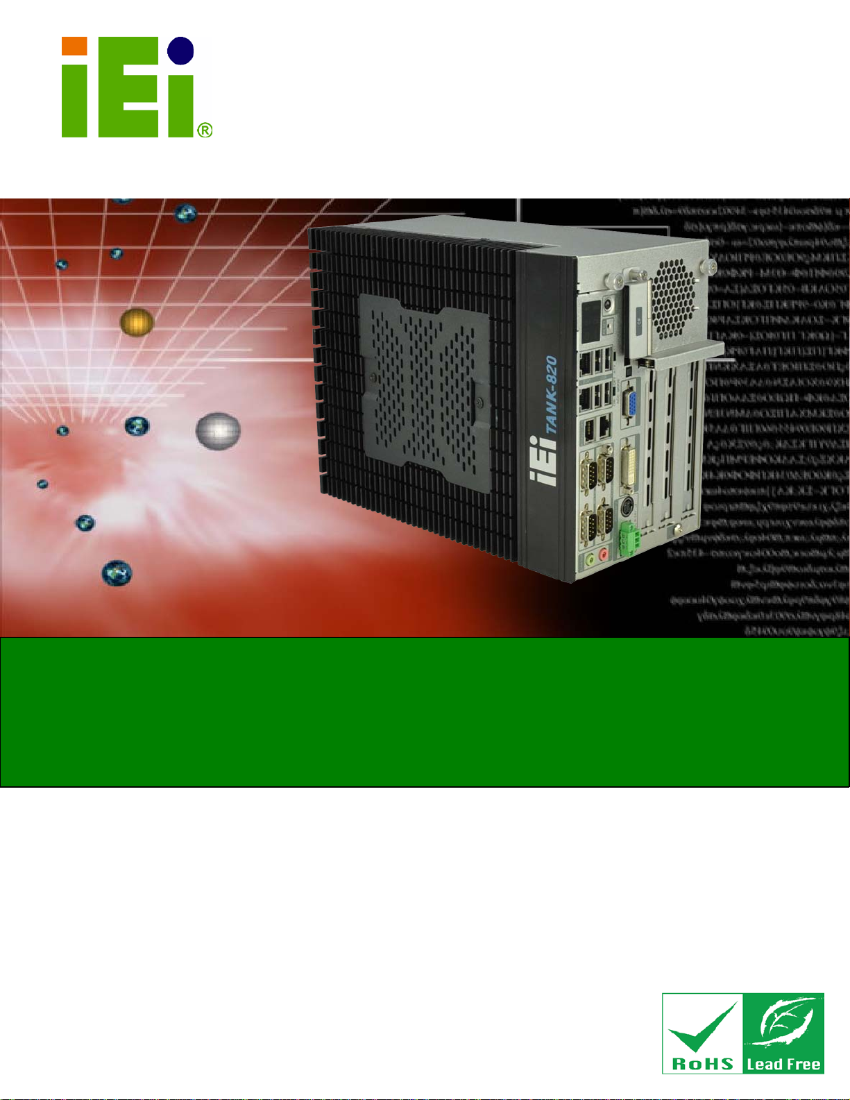
The TANK-820 is an embedded system for wide ran ge temperature environments. It is
powered by the 2nd Generation Intel® Core™ low power desktop processor, uses the
Intel® H61 chipset and has 2.0 GB of DDR3 memory on-board. The TANK-820 series
includes on e VGA port, one DVI-I port, two G bE LAN ports, four USB 2. 0 ports, two USB
3.0 ports, six RS-232 connectors and two RS-422/485 connectors.
Page 16

TANK-820 Emb edded System
Page 3
1.2 Mo del Variations
The model variations of the TANK-820 series are listed below.
Model No. CPU Expans ion Slots
TANK-820-H61/2GB
/2P1E-R10
TANK-820-H61/2GB
/1P2E-R10
Table 1-1: TANK-820 Model Variations
2nd Generation Intel® Core™
low power desktop processor
2nd Generation Intel® Core™
low power desktop processor
1.3 Features
The TANK-820 features are listed below:
2nd Generation Intel® Core™ low power desktop processors for TANK-820
On-board 2GB DDR3 memory and one DDR3 SO-DIMM slot (system max.
10GB) for TANK-820
Redundant dual wild range DC power support (TANK-820: 9 ~ 24 VDC)
Flexible PCI/PCIe expansion slots satisfy customized requirements
Rich I/O functions satisfy various applications
Two PCI slots
One PCIe x16 slot (PCIe x8 signal)
One PCI slot
One PCIe x4 slot (PCIe x1 signal)
One PCIe x16 slot (PCIe x8 signal)
Dual PCIe GbE LAN for high speed network applications
One CompactFlash® socket
1.4 Technical Specifications
The TANK-820 technical specifications are listed in Table 1-2.
Specifications
System
CPU
Chipset
Memo ry
2nd Generation Intel® Core™ low power desktop processor
Intel® H61
1 x 204-pin DDR3 SDRAM SO-DIMM slot (Max. to 10G)
On-board 2GB DDR3 memory
Page 17

TANK-820 Embedded Sys tem
Page 4
Specifications
Ethernet Controller
I/O and Indicators
Ethernet
RS-232
RS-422/RS-485
USB Interfaces
Display
Audio Connector
Digital I/O
Interior Expansions
Dual Realtek RTL8111E PCIe GbE controllers with ASF 2.0 support
2 x RJ-45 GbE ports
4 x RS-232 serial ports (DB-9)
2 x RS-232 serial ports (DB-9 with isolation)
2 x RS-422/485 serial ports (RJ-45)
4 x USB 2.0 ports on front side
2 x USB 3.0 ports on rear side
1 x VGA port (2048 x 1536 @ 75Hz)
1 x DVI-I port (1920 x 1080 @ 60Hz)
1 x Line-out port
1 x Mic-in port
1 x DB-9 port on rear side
Either one PCIe x8 (via PCIe x16 slot) and two PCI
LED Indicators
Storage
SATA
CompactFlash®
Power
Power Supply
or one PCIe x1 (via PCIe x4 slot), one PCIe x8 (via PCIe x16 slot)
and one PCI
AT power mode LED
ATX power mode LED
CPU temperature alert LED
HDD LED
Power 1 LED
Power 2 LED
2.5’’ SATA HDD bay
One CompactFlash® Type II socket
Redundant dual DC input
Terminal Block: 9 ~ 24V
DC Jack: 9 ~ 24V
Page 18

TANK-820 Emb edded System
Page 5
Specifications
Power Consumption
Environmental and Mechanical
Operating Temperature
Storage Temperature
Humidity
Mounting
Color
Chassis Construction
Phys ical Dimensions
Operating Shock
Operating Vibration
Weight (Net/Gross)
Safety & EMC
19V@3.5A (Intel® Core™ i3-2100 processor with 6GB DDR3
memory) without add-on card
-20°C ~ 60°C with air flow
-30°C~80°C
5% ~ 95%, non-condensing
Desktop, wall mount
Black C + Silve r
Extruded Aluminum Alloy
133 mm x 206 mm x 269 mm (W x H x D)
Half-sine wave shock 5G, 11ms, 3 axis
Meet MIL-STD-810F 514.5C-2 (with SSD)
4.2 Kg / 6.3 Kg
CE / FCC
Table 1-2: Technical Specifications
Page 19

TANK-820 Embedded Sys tem
Page 6
1.5 Front Panel
The front panel of the TANK-820 has the following features (Figure 1-2):
Figure 1-2: TANK-820 Front Panel
Connectors and buttons on the front panel include the following:
1 x 4-pin power DC jack for 9 V ~ 24 V power input
1 x Power terminal block for 9 V ~ 24 V power input
1 x Mic-in port (pink)
1 x Line-out port (green)
4 x RS-232 serial ports (DB-9)
2 x RS-422/485 serial ports (RJ-45)
2 x Gigabit Ethernet ports (RJ-45)
Page 20

TANK-820 Emb edded System
Page 7
4 x USB 2.0 ports
1 x Reset button
6 x LED indicators (Section 1.7)
1 x Power button
1 x CompactFlash® Type II socket
1 x VGA port
1 X DVI-I port
1 x To Ground
3 x Expansion slots
1 x ACC mode switch
1 x AT/ATX mode switch
1.6 Rear Panel
The rear panel of the TANK-820 has the following features (Figure 1-2):
Figure 1-3: TANK-820 Rear Panel
Connectors on the front panel include the following:
1 x DIO connector
2 x RS-232 serial ports (DB-9 with isolation)
2 x USB 3.0 ports
Page 21

TANK-820 Embedded Sys tem
Page 8
1.7 LED Indicators
There are several indicators on the rear panel of the TANK-820 as shown in Figure 1-4.
Figure 1-4: TANK-820 LED Indicators
The descriptions of each LED indicator are listed below.
LED Indicator Description
AT Power Mode
ATX Power Mode
Power 1
Power 2
HDD
CPU Temperature Alert
Table 1-3: LED Indicators Description
The current power mode status is A T mode.
Controlled by the AT/ATX power mode switch.
The current power mode status is ATX mode.
Controlled by the AT/ATX power mode switch.
Breathing orange: Standby mode.
Solid blue: Power-on mode.
Shows HDD status.
BLUE: CPU temperature is normal.
RED: CPU temperature is too high.
WARNING:
The CPU Temperature Alert LED turns red when the CPU temperature
is too high. If this situation occurs, lower the enviro nment tem perature
or close some running applications to cool down the CPU.
Page 22

TANK-820 Emb edded System
Page 9
1.8 Backplane Options
The backplane options of the TANK-820 are shown below.
Figure 1-5: HPE-3S6 (2P1E)
Figure 1-6: HPE-3S7 (1P2E)
The supported signals of the backplane slots are listed below.
Backplane Slot Signal
HPE-3S6 (2P1E)
HPE-3S7 (1P2E)
Table 1-4: Supported Signals
The rated voltage and current of the backplanes are listed below.
Rated Voltage Rated Current
+5 V 7 A
PCI PCI
PCIe x16 PCIe x8
PCI PCI
PCIe x4 PCIe x1
PCIe x16 PCIe x8
Page 23

TANK-820 Embedded Sys tem
Page 10
+12 V 3.75 A
-12 V 0.1 A
+3.3 V 8 A
Table 1-5: Rated Voltage and Current
WARNING:
The system default power is 120 W. The maximum total power of the
backplane to support expansion cards is 45 W. The power of the
selected expansion cards can not exceed the max. power (45 W),
otherwise, the system may be unstable.
NOTE:
When using an expansion card with high power consumption, it is
recommended to install an external power supply to the 12V power
input connector on the backplane.
Page 24

TANK-820 Emb edded System
Page 11
1.9 Dimensions
The physical dimensions are shown below:
Figure 1-7: Physical Dimensions (millimeters)
Page 25

TANK-820 Embedded Sys tem
Page 12
Chapter
2
2 Unpacking
Page 26

TANK-820 Emb edded System
Page 13
may result in
2.1 Anti-static Precautions
WARNING:
Failure to take ESD precautions during installation
permanent damage to the TANK-820 and severe injury to the user.
Electrostatic discharge (ESD) can cause serious damage to electronic components,
including the TANK-820. D ry climates are especially susceptible to E SD. It is therefore
critical that whenever the TANK-820 or any other electrical component is handled, the
following anti-static precautions are strictly adhered to.
Wear an anti-static wristband: Wearing a simple anti-static wristband can
help to prevent ESD from damaging the board.
Self-grounding: Before handling the board touch any grounded conducting
material. During the time the board is handled, frequently touch any
conducting materials that are connected to the ground.
Use an anti-static pad: When configuring the TANK-820, place it on an
antic-static pad. This reduces the possibility of ESD damaging the TANK-820.
2.2 Unpacking Precautions
When the TANK-820 is unpacked, please do the following:
Follow the anti-static precautions outlined in Section 2.1.
Make sure the packing box is facing upwards so the TANK-820 does not fall
out of the box.
Make sure all the components shown in Section 2.3 are present.
Page 27

TANK-820 Embedded Sys tem
Page 14
2.3 Unpacking Checklist
NOTE:
If some of the components listed in the checklist below are missing,
please do not proceed with the installation. Contact the IEI resel ler or
vendor you purchased the TANK-820 from or contact an IEI sales
representative direct ly. To contact an IEI s ales representati ve, please
send an email to
The TANK-820 is shipped with the following components:
Quantity Item and Part Number Im a g e
Standard
1 TANK-820
1 Power Adapter
(P/N: 63000-FSP120AAB-RS)
sales@iei.com.tw.
1 Power Cord
(P/N: 32702-000401-100-RS)
1 Power Transfer Cord
(P/N: 32702-000300-100-RS)
4 Mounting Bracket Screws
(P/N: 44033-040062-RS)
 Loading...