

Page 1

User Manual
TANK-800 Embedded System
MODEL:
TANK-800
Fanless Embedded System with Intel® Atom™ D525
Dual Core CPU, VGA, Two Gigabit Ethernet, Four USB,
RS-232/422/485, RoHS Compliant
Rev. 1.14 – 2 September, 2013
Page i
Page 2

TANK-800 Embedded System
Revision
Date Version Changes
2 September, 2013 1.14 Updated Section 3.4: System Fan Installation
2 April, 2013 1.13 Added the maximum dimensions of an expansion card in
Section
5 February, 2013 1.12 Updated the optional system fan P/N
10 May, 2012 1.11 Updated Section 1.7: Backplane Options
5 December, 2011 1.10 Updated Section 2.3: Unpacking Checklist
Updated Section
Updated Appendix A: One Key Recovery
3 November, 2011 1.00 Initial release
1.7
3.7.9: RJ-45 RS-422/485 Serial Ports
Page ii
Page 3

TANK-800 Embedded System
COPYRIGHT NOTICE
The information in this document is subject to change without prior notice in order to
improve reliability, design and function and does not represent a commitment on the part
of the manufacturer.
In no event will the manufacturer be liable for direct, indirect, special, incidental, or
consequential damages arising out of the use or inability to use the product or
documentation, even if advised of the possibility of such damages.
This document contains proprietary information protected by copyright. All rights are
Copyright
reserved. No part of this manual may be reproduced by any mechanical, electronic, or
other means in any form without prior written permission of the manufacturer.
TRADEMARKS
All registered trademarks and product names mentioned herein are used for identification
purposes only and may be trademarks and/or registered trademarks of their respective
owners.
Page iii
Page 4

TANK-800 Embedded System
WARNING
This device complies with Part 15 of the FCC Rules. Operation is subject to the following
two conditions:
(1) this device may not cause harmful interference, and(2) this device must accept any
interference received, including interference that may cause u ndesired operation.
NOTE: This equipment has been tested and found to comply with the limits for a Class
B digital device, pursuant to part 15 of the FCC Rules. These limits are designed to
provide reasonable protection against harmful interference in a residential installation.
This equipment generates, uses and can radiate radio frequency energy and, if not
installed and used in accordance with the instructions, may cause harmful interference
to radio communications.
However, there is no guarantee that interference will not occur in a particular
installation. If this equipment does cause harmful interference to radio or television
reception, which can be determined by turning the equipment off and on, the user is
encouraged to try to correct the interference by one or more of the following measures:
—
Reorient or relocate the receiving antenna.
—
Increase the separation between the equipment and receiver.
—
Connect the equipment into an outlet on a circuit different from that to which the
receiver is connected.
—
Consult the dealer or an experienced radio/ TV technician for help.
You are cautioned that any change or modifications to the equipment not expressly
approve by the party responsible for compliance could void your authority to operate
such equipment.
IMPORTANT NOTE:
FCC Radiation Exposure Statement:
This equipment complies with FCC radiation exposure limits set forth for an
uncontrolled environment. This equipment should be installed and operated with
minimum distance 20cm between the radiator & your body
Page iv
.
Page 5

TANK-800 Embedded System
Table of Contents
1 INTRODUCTION.......................................................................................................... 1
1.1 OVERVIEW.................................................................................................................. 2
1.2 MODEL VARIATIONS ................................................................................................... 3
1.3 FEATURE S................................................................................................................... 3
1.4 TECHNICAL SPECIFICATIONS ...................................................................................... 4
1.5 CONNECTOR PANEL.................................................................................................... 6
1.6 LED INDICATORS ....................................................................................................... 7
1.7 BACKPLANE OPTIONS ................................................................................................ 8
1.8 DIMENSIONS............................................................................................................. 10
2 UNPACKING................................................................................................................11
2.1 ANTI-STATIC PRECAUTIONS...................................................................................... 12
2.2 UNPACKING PRECAUTIONS....................................................................................... 12
2.3 UNPACKING CHECKLIST ........................................................................................... 13
3 INSTALLATION ......................................................................................................... 16
3.1 INSTALLATION PRECAUTIONS................................................................................... 17
3.2 CF CARD INSTALLATION .......................................................................................... 17
3.3 HARD DISK DRIVE (HDD) INSTALLATION................................................................ 19
3.4 SYSTEM FAN INSTALLATION..................................................................................... 22
3.5 PLUGGABLE DC-IN TERMINAL BLOCK INSTALLATION ............................................. 25
3.6 MOUNTING THE SYSTEM WITH MOUNTING BRACKETS ............................................ 26
3.7 EXTERNAL PERIPHERAL INTERFACE CONNECTORS................................................... 27
3.7.1 ACC Mode Selection ........................................................................................ 28
3.7.2 AT/ATX Power Mode Selection........................................................................ 28
3.7.3 Audio Connector .............................................................................................. 29
3.7.4 CompactFlash® Type II................................................................................... 29
3.7.5 Digital Input/Output Connector....................................................................... 29
3.7.6 LAN Connectors............................................................................................... 30
3.7.7 Power Input, 3-pin Terminal Block.................................................................. 32
3.7.8 Power Input, 4-pin DIN Connector ................................................................. 32
Page v
Page 6

3.7.9 RJ-45 RS-422/485 Serial Ports........................................................................ 33
3.7.10 RS-232 Serial Port Connectors...................................................................... 35
3.7.11 USB Connectors............................................................................................. 37
3.7.12 VGA Connector.............................................................................................. 38
3.8 POWERING ON/OFF THE SYSTEM ............................................................................. 40
3.9 REDUNDANT POWER ................................................................................................ 40
3.9.1 ACC ON ........................................................................................................... 41
3.9.1.1 Boot-up ..................................................................................................... 42
3.9.1.2 Switch to Backup Power........................................................................... 42
3.9.1.3 Shutdown .................................................................................................. 43
3.9.2 ACC OFF......................................................................................................... 44
3.9.2.1 Boot-up ..................................................................................................... 44
3.9.2.2 Switch to Backup Power........................................................................... 44
3.9.2.3 Shutdown .................................................................................................. 45
TANK-800 Embedded System
4 BIOS.............................................................................................................................. 46
4.1 INTRODUCTION......................................................................................................... 47
4.1.1 Starting Setup................................................................................................... 47
4.1.2 Using Setup...................................................................................................... 47
4.1.3 Getting Help..................................................................................................... 48
4.1.4 Unable to Reboot After Configuration Changes.............................................. 48
4.1.5 BIOS Menu Bar................................................................................................ 48
4.2 MAIN........................................................................................................................ 49
4.3 ADVANCED............................................................................................................... 50
4.3.1 ACPI Settings................................................................................................... 51
4.3.2 CPU Configuration.......................................................................................... 52
4.3.3 IDE Configuration........................................................................................... 53
4.3.4 USB Configuration........................................................................................... 55
4.3.5 Super IO Configuration ................................................................................... 56
4.3.5.1 Serial Port n Configuration....................................................................... 57
4.3.6 H/W Monitor.................................................................................................... 63
4.3.7 Serial Port Console Redirection...................................................................... 64
4.3.8 iEi Feature........................................................................................................ 66
4.4 CHIPSET ................................................................................................................... 67
4.4.1 Host Bridge Configuration .............................................................................. 68
Page vi
Page 7

TANK-800 Embedded System
4.4.2 South Bridge Configuration............................................................................. 68
4.4.3 Intel IGD SWSCI OpRegion............................................................................. 70
4.5 BOOT........................................................................................................................ 71
4.6 SECURITY................................................................................................................. 72
4.7 EXIT......................................................................................................................... 74
A ONE KEY RECOVERY............................................................................................. 76
A.1 ONE KEY RECOVERY INTRODUCTION...................................................................... 77
A.1.1 System Requirement......................................................................................... 78
A.1.2 Supported Operating System........................................................................... 79
A.2 SETUP PROCEDURE FOR WINDOWS.......................................................................... 80
A.2.1 Hardware and BIOS Setup .............................................................................. 81
A.2.2 Create Partitions............................................................................................. 81
A.2.3 Install Operating System, Drivers and Applications....................................... 85
A.2.4 Build-up Recovery Partition............................................................................ 86
A.2.5 Create Factory Default Image......................................................................... 88
A.3 AUTO RECOVERY SETUP PROCEDURE...................................................................... 93
A.4 SETUP PROCEDURE FOR LINUX................................................................................ 97
A.5 RECOVERY TOOL FUNCTIONS ................................................................................ 101
A.5.1 Factory Restore............................................................................................. 102
A.5.2 Backup System............................................................................................... 103
A.5.3 Restore Your Last Backup.............................................................................. 104
A.5.4 Manual........................................................................................................... 105
A.6 RESTORE SYSTEMS FROM A LINUX SERVER THROUGH LAN.................................. 106
A.6.1 Configure DHCP Server Settings.................................................................. 107
A.6.2 Configure TFTP Settings............................................................................... 108
A.6.3 Configure One Key Recovery Server Settings............................................... 109
A.6.4 Start the DHCP, TFTP and HTTP..................................................................110
A.6.5 Create Shared Directory.................................................................................110
A.6.6 Setup a Client System for Auto Recovery.......................................................111
A.7 OTHER INFORMATIO N.............................................................................................114
A.7.1 Using AHCI Mode or ALi M5283 / VIA VT6421A Controller........................114
A.7.2 System Memory Requirement .........................................................................116
B SAFETY PRECAUTIONS........................................................................................117
Page vii
Page 8

B.1 SAFETY PRECAUTIONS............................................................................................118
B.1.1 General Safety Precautions............................................................................118
B.1.2 Anti-static Precautions...................................................................................119
B.1.3 Product Disposal........................................................................................... 120
B.2 MAINTENANCE AND CLEANING PRECAUTIONS ...................................................... 120
B.2.1 Maintenance and Cleaning............................................................................ 120
B.2.2 Cleaning Tools............................................................................................... 121
C HAZARDOUS MATERIALS DISCLOSURE....................................................... 122
C.1 HAZARDOUS MATERIALS DISCLOSURE TABLE FOR IPB PRODUCTS CERTIFIED AS
ROHS COMPLIANT UNDER 2002/95/EC WITHOUT MERCURY ..................................... 123
TANK-800 Embedded System
Page viii
Page 9

TANK-800 Embedded System
List of Figures
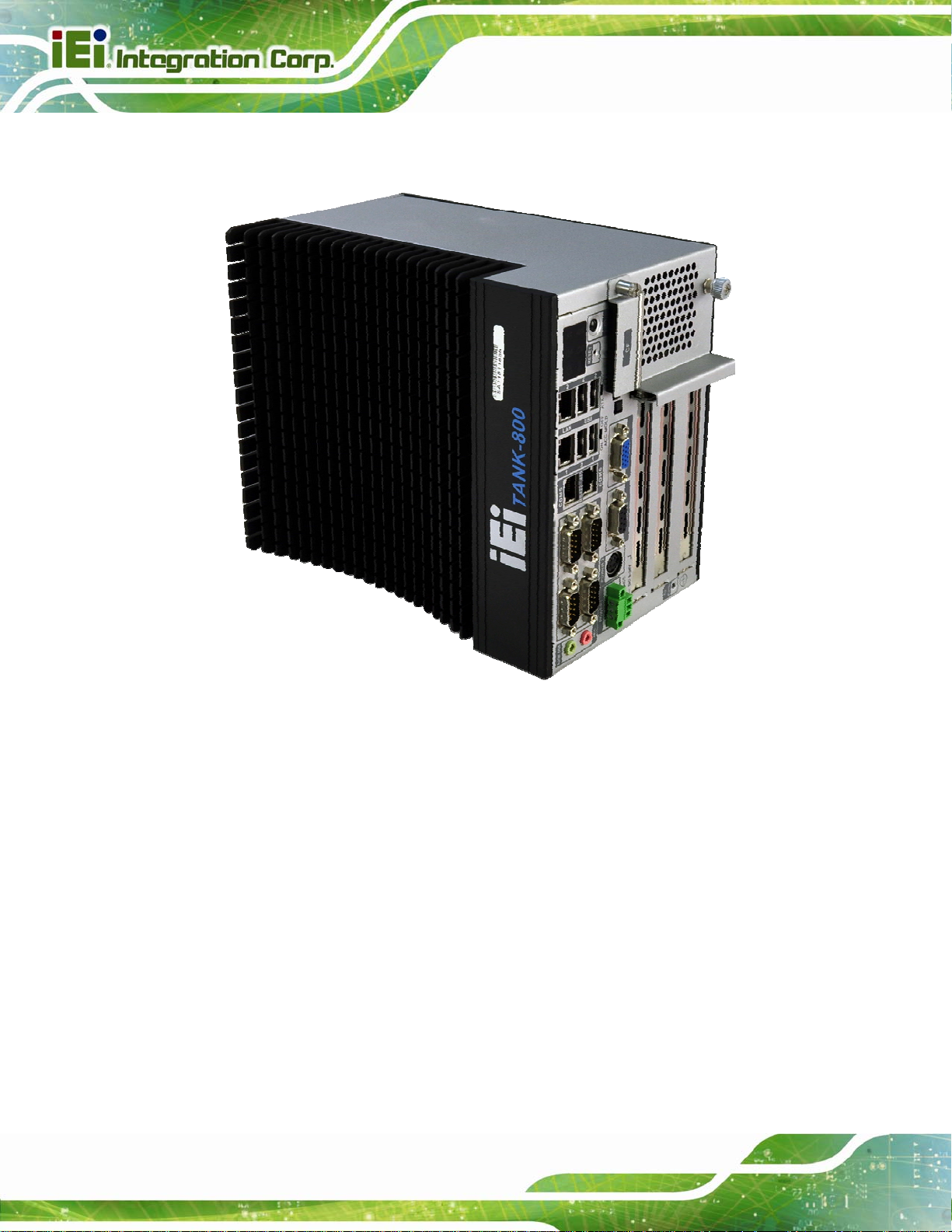
Figure 1-1: TANK-800.....................................................................................................................2
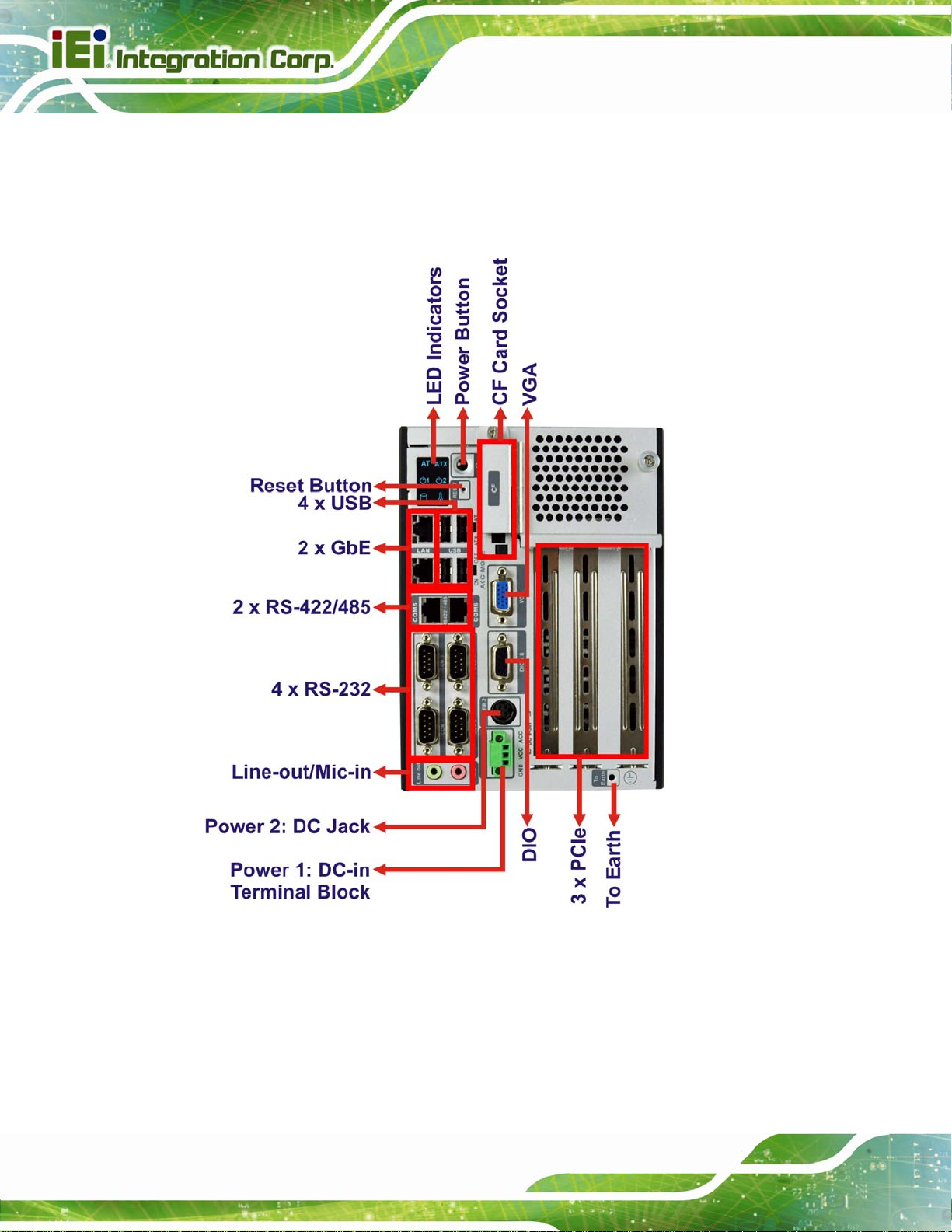
Figure 1-2: TANK-800 Peripheral Connectors.............................................................................6
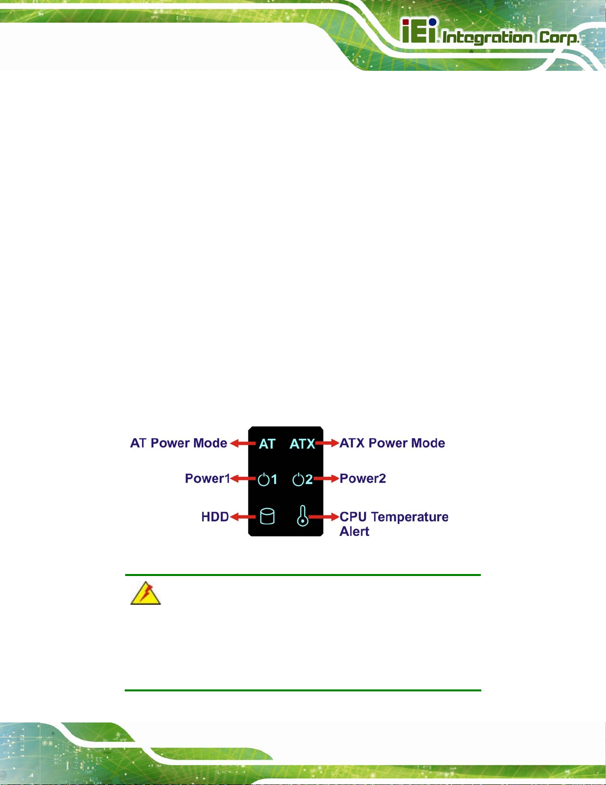
Figure 1-3: TANK-800 LED Indicators...........................................................................................7
Figure 1-4: TANK-800-D525/1GB/2P1E-R10 Backplane (HPE-3S6) ...........................................8
Figure 1-5: TANK-800-D525/1GB/1P2E-R10 Backplane (HPE-3S7) ...........................................8
Figure 1-6: Physical Dimensions (millimeters)..........................................................................10
Figure 3-1: CF Card Slot ..............................................................................................................18
Figure 3-2: CF Card Slot Cover...................................................................................................18
Figure 3-3: CF Card Installation..................................................................................................19
Figure 3-4: Unscrew the Cover....................................................................................................20
Figure 3-5: Remove the Cover from TANK-800.........................................................................20
Figure 3-6: HDD Installation ........................................................................................................21
Figure 3-7: HDD Retention Screws.............................................................................................21
Figure 3-8: Remove the HDD Bracket from the Cover..............................................................22
Figure 3-9: Remove the Fan Bracket from the Cover ...............................................................23
Figure 3-10: Remove the Temporary Retaining Bracket..........................................................23
Figure 3-11: Secure the System Fan to the Fan Bracket..........................................................24
Figure 3-12: Reinstall the Fan Bracket.......................................................................................24
Figure 3-13: Pluggable DC-in Terminal Block Installation .......................................................25
Figure 3-14: Mounting Bracket Retention Screws ....................................................................26
Figure 3-15: ACC Mode Switch ...................................................................................................28
Figure 3-16: AT/ATX Power Mode Switch ..................................................................................28
Figure 3-17: Audio Connector.....................................................................................................29
Figure 3-18: DIO Connector Pinout Location ............................................................................30
Figure 3-19: LAN Connection......................................................................................................31
Figure 3-20: RJ-45 Ethernet Connector......................................................................................31
Figure 3-21: 3-pin Terminal Block Pinout Location ..................................................................32
Figure 3-22: Power Input Connector...........................................................................................33
Figure 3-23: RJ-45 RS-422/485 Serial Device Connection........................................................34
Figure 3-24: RJ-45 RS-422/485 Serial Port Pinout Location.....................................................34
Page ix
Page 10

Figure 3-25: DB-9 Connector Pinout Location ..........................................................................35
Figure 3-26: Serial Device Connector.........................................................................................36
Figure 3-27: Serial Port Pinout Location....................................................................................36
Figure 3-28: USB Device Connection.........................................................................................37
Figure 3-29: VGA Connector .......................................................................................................39
Figure 3-30: VGA Connector .......................................................................................................39
Figure 3-31: Power Button...........................................................................................................40
Figure 3-32: Power Connectors ..................................................................................................41
Figure 3-33: ACC On: AT Mode...................................................................................................42
Figure 3-34: ACC On: ATX Mode.................................................................................................42
Figure 3-35: ACC On: Switch Between PWR1 and PWR2 ........................................................43
Figure 3-36: ACC On: Shutdown.................................................................................................43
Figure 3-37: ACC Off: AT Mode...................................................................................................44
Figure 3-38: ACC Off: ATX Mode ................................................................................................44
TANK-800 Embedded System
Figure 3-39: ACC Off: Switch Between PWR1 and PWR2........................................................45
Figure 3-40: ACC Off: Shutdown.................................................................................................45
Figure A-1: IEI One Key Recovery Tool Menu...........................................................................77
Figure A-2: Launching the Recovery Tool.................................................................................82
Figure A-3: Recovery Tool Setup Menu .....................................................................................82
Figure A-4: Command Mode........................................................................................................83
Figure A-5: Partition Creation Commands.................................................................................84
Figure A-6: Launching the Recovery Tool.................................................................................86
Figure A-7: System Configuration for Windows .......................................................................86
Figure A-8: Building the Recovery Partition..............................................................................87
Figure A-9: Press Any Key to Continue.....................................................................................87
Figure A-10: Press F3 to Boot into Recovery Mode..................................................................88
Figure A-11: Recovery Tool Menu ..............................................................................................88
Figure A-12: About Symantec Ghost Window...........................................................................89
Figure A-13: Symantec Ghost Path ............................................................................................89
Figure A-14: Select a Local Source Drive ..................................................................................90
Figure A-15: Select a Source Partition from Basic Drive .........................................................90
Figure A-16: File Name to Copy Image to ..................................................................................91
Figure A-17: Compress Image.....................................................................................................91
Figure A-18: Image Creation Confirmation................................................................................92
Figure A-19: Image Creation Process.........................................................................................92
Page x
Page 11

TANK-800 Embedded System
Figure A-20: Image Creation Complete......................................................................................92
Figure A-21: Press Any Key to Continue...................................................................................93
Figure A-22: Auto Recovery Utility.............................................................................................94
Figure A-23: Launching the Recovery Tool...............................................................................94
Figure A-24: Auto Recovery Environment for Windows ..........................................................94
Figure A-25: Building the Auto Recovery Partition...................................................................95
Figure A-26: Factory Default Image Confirmation ....................................................................95
Figure A-27: Image Creation Complete......................................................................................96
Figure A-28: Press any key to continue.....................................................................................96
Figure A-29: Partitions for Linux.................................................................................................98
Figure A-30: Manual Recovery Environment for Linux ............................................................99
Figure A-31: Access menu.lst in Linux (Text Mode).............................................................. 100
Figure A-32: Recovery Tool Menu ........................................................................................... 100
Figure A-33: Recovery Tool Main Menu.................................................................................. 101
Figure A-34: Restore Factory Default...................................................................................... 102
Figure A-35: Recovery Complete Window.............................................................................. 103
Figure A-36: Backup System.................................................................................................... 103
Figure A-37: System Backup Complete Window ................................................................... 104
Figure A-38: Restore Backup................................................................................................... 104
Figure A-39: Restore System Backup Complete Window..................................................... 105
Figure A-40: Symantec Ghost Window ................................................................................... 105
Page xi
Page 12

TANK-800 Embedded System
List of Tables
Table 1-1: TANK-800 Model Variations.........................................................................................3
Table 1-2: Technical Specifications..............................................................................................5
Table 1-3: Supported Signals........................................................................................................8
Table 1-4: Rated Voltage and Current ..........................................................................................9
Table 3-1: DIO Connector Pinouts..............................................................................................30
Table 3-2: LAN Pinouts ................................................................................................................31
Table 3-3: RJ-45 Ethernet Connector LEDs...............................................................................32
Table 3-4: Power Input Pinouts...................................................................................................33
Table 3-5: RJ-45 RS-422/485 Serial Port Pinouts ......................................................................34
Table 3-6: DB-9 Connector Pinouts............................................................................................35
Table 3-7: Serial Port Pinouts......................................................................................................36
Table 3-8: USB Port Pinouts........................................................................................................38
Table 3-9: VGA Connector Pinouts.............................................................................................39
Table 4-1: BIOS Navigation Keys................................................................................................48
TANK-800
Page xii
Page 13

TANK-800 Embedded System
Chapter
1
1 Introduction
Page 1
Page 14
1.1 Overview
TANK-800 Embedded System
Page 2
Figure 1-1: TANK-800
The TANK-800 Series embedded system is a fanless system for wide range temperature
environments. It is powered by the Intel® Atom D525 dual core processor, uses the
Intel® ICH8M chipset and has 1.0 GB of DDR3 memory. The TANK-800 Series includes
one VGA port, two PCIe GbE LAN, four USB 2.0 ports, and six COM ports.
Page 15

TANK-800 Embedded System
1.2 Model Variations
The model variations of the TANK-800 Series are listed below.
Model No. CPU Expansion Slots
TANK-800-D525/1GB/2P1E-R10
TANK-800-D525/1GB/1P2E-R10
Table 1-1: TANK-800 Model Variations
1.3 Features
The TANK-800 features are listed below:
Intel® Atom D525 1.8 GHz dual core processor
On-board 1.0 GB DDR3 memory
Redundant dual DC input
Flexible PCI/PCIe expansion slots
Two Gigabit Ethernet ports
Four USB 2.0 ports
Four RS-232 serial ports
Intel® Atom D525 1.8 GHz
dual core
Intel® Atom D525 1.8 GHz
dual core
Two PCI slots
One PCIe x16 slot
One PCI slot
One PCIe x4 slot
One PCIe x16 slot
Two RJ-45 RS-422/485 serial ports
One VGA port
One Line-out and one Mic-in audio jacks
One CompactFlash® Type II socket
AT/ATX power mode supported
RoHS compliant
Page 3
Page 16

1.4 Technical Specifications
The TANK-800 technical specifications are listed in Table 1-2.
Specifications
System
TANK-800 Embedded System
CPU
Chipset
Memory
Ethernet Controller
I/O and Indicators
Ethernet
RS-232
RS-422/RS-485
USB Interfaces
VGA
Audio Connector
1.8 GHz Intel® Atom D525 dual core CPU
Intel® ICH8M
On-board 1.0 GB DDR3 memory
1 x 204-pin 800 MHz DDR3 SDRAM SO-DIMM slot
(system max. 2.0 GB)
Dual Realtek RTL8111E PCIe GbE controllers with ASF 2.0 support
2 x RJ-45 GbE ports
4 x RS-232 serial ports (DB-9)
2 x RS-422/485 serial ports (RJ-45)
4 x USB 2.0 ports
1 x VGA port (2048x1536)
1 x Line-out port
1 x Mic-in port
Digital I/O
LED Indicators
Storage
SATA
CompactFlash®
Page 4
1 x DIO port (8 bits)
AT power mode LED
ATX power mode LED
CPU temperature alert LED
HDD LED
Power 1 LED
Power 2 LED
Support one 2.5” SATA HDD
One CompactFlash® Type II socket
Page 17

TANK-800 Embedded System
Specifications
Power
Power Supply
Power Consumption
Power Button
Power Mode
Environmental and Mechanical
Operating Temperature
Storage Temperature
Mounting
Color
Physical Dimensions
Table 1-2: Technical Specifications
Redundant dual DC input 9V~36V
Power 1 (terminal block): 9 V (+/-0.3 V) ~ 36 V
Power 2 (DC jack): 10.5 V (+/-0.3 V) ~ 36 V
33 W (without add-on card)
One power button
AT or ATX power mode (selectable by AT/ATX mode switch)
-20°C~70°C
-30°C~80°C
Desktop, wall mount
Black C + Silver
136 mm x 219 mm x 188 mm (W x D x H)
Page 5
Page 18
1.5 Connector Panel
All external peripheral interface connectors are located on the rear panel of the TANK-800.
TANK-800 Embedded System
The peripheral interface connectors are shown in
Figure 1-2.
Page 6
Figure 1-2: TANK-800 Peripheral Connectors
Connectors and buttons on the rear panel include the following.
1 x 4-pin power DC jack for 10.5V (+/-0.3V) ~ 36V power input
1 x Power terminal block for 9V (+/-0.3V) ~ 36V power input
1 x Mic-in port (pink)
Page 19
TANK-800 Embedded System
1 x Line-out port (green)
4 x RS-232 serial ports
2 x RJ-45 RS-422/485 serial ports
2 x Gigabit Ethernet ports
4 x USB ports
1 x Reset button
6 x LED indicators (Section
1 x Power button
1 x CompactFlash® Type II socket
1 x VGA output
1 x To earth
3 x Expansion slots
1 x DIO port
1 x ACC mode switch
1 x AT/ATX power mode switch
1.6 LED Indicators
There are several indicators on the rear panel of the TANK-800 as shown in Figure 1-3.
1.6)
Figure 1-3: TANK-800 LED Indicators
WARNING:
The CPU Temperature Alert LED turns red when the CPU temperature
is too high. If this situation occurs, lower the environment temperature
or close some running applications to cool down the CPU.
Page 7
Page 20
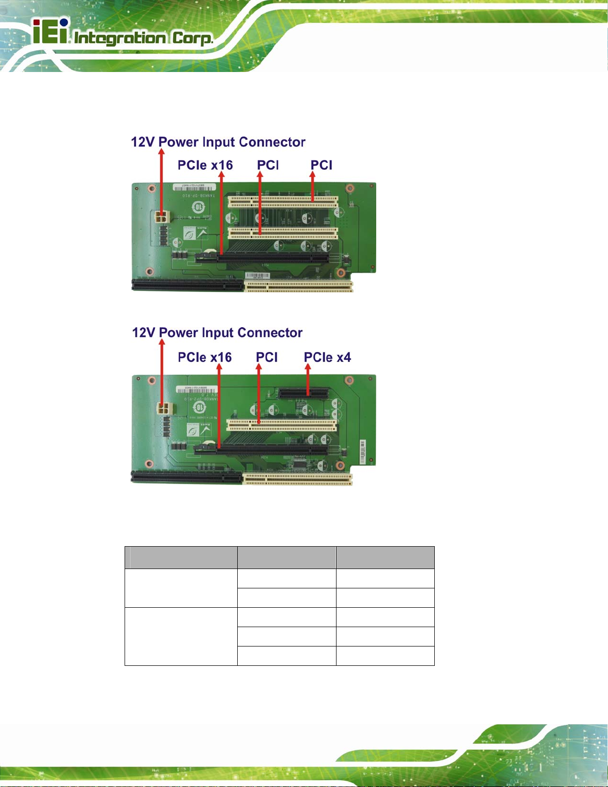
1.7 Backplane Options
The backplane options of the TANK-800 are shown below.
Figure 1-4: TANK-800-D525/1GB/2P1E-R10 Backplane (HPE-3S6)
TANK-800 Embedded System
Page 8
Figure 1-5: TANK-800-D525/1GB/1P2E-R10 Backplane (HPE-3S7)
The supported signals of the backplane slots are listed below.
Backplane Slot Signal
HPE-3S6 (2P1E)
HPE-3S7 (1P2E)
Table 1-3: Supported Signals
PCI PCI
PCIe x16 PCIe x4
PCI PCI
PCIe x4 PCIe x1
PCIe x16 PCIe x2
Page 21
TANK-800 Embedded System
The rated voltage and current of the backplanes are listed below.
Rated Voltage Rated Current
+5 V 7 A
+12 V 3.75 A
-12 V 0.1 A
+3.3 V 8 A
Table 1-4: Rated Voltage and Current
WARNING:
The system default power is 96 W. The maximum total power of the
backplane to support expansion cards is 45 W. The power of the
selected expansion cards can not exceed the max. power (45 W),
otherwise, the system may fail.
NOTE:
When using an expansion card with high power consumption, it is
recommended to install an external power supply to the 12V power
input connector on the backplane.
The maximum dimensions of the expansion card should be 190 mm in
length and 111 mm in width.
Page 9
Page 22
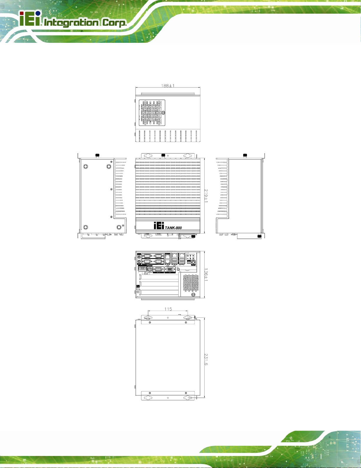
1.8 Dimensions
The physical dimensions are shown below:
TANK-800 Embedded System
Page 10
Figure 1-6: Physical Dimensions (millimeters)
Page 23

TANK-800 Embedded System
Chapter
2
2 Unpacking
Page 11
Page 24

2.1 Anti-static Precautions
WARNING:
Failure to take ESD precautions during installation may result in
permanent damage to the TANK-800 and severe injury to the user.
Electrostatic discharge (ESD) can cause serious damage to electronic components,
including the TANK-800. Dry climates are especially susceptible to ESD. It is therefore
critical that whenever the TANK-800 or any other electrical component is handled, the
following anti-static precautions are strictly adhered to.
Wear an anti-static wristband: Wearing a simple anti-static wristband can
help to prevent ESD from damaging the board.
TANK-800 Embedded System
Self-grounding: Before handling the board touch any grounded conducting
material. During the time the board is handled, frequently touch any
conducting materials that are connected to the ground.
Use an anti-static pad: When configuring the TANK-800, place it on an
antic-static pad. This reduces the possibility of ESD damaging the TANK-800.
2.2 Unpacking Precautions
When the TANK-800 is unpacked, please do the following:
Follow the anti-static precautions outlined in Section
Make sure the packing box is facing upwards so the TANK-800 does not fall
out of the box.
Make sure all the components shown in Section
2.1.
2.3 are present.
Page 12
Page 25
TANK-800 Embedded System
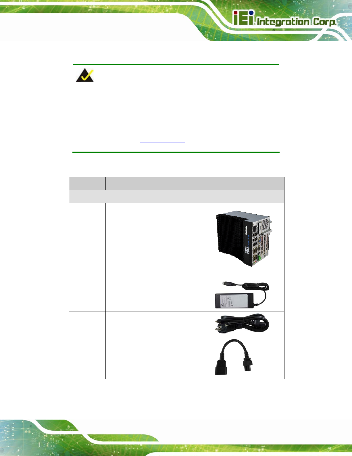
2.3 Unpacking Checklist
NOTE:
If some of the components listed in the checklist below are missing,
please do not proceed with the installation. Contact the IEI reseller or
vendor you purchased the TANK-800 from or contact an IEI sales
representative directly. To contact an IEI sales representative, please
send an email to
The TANK-800 is shipped with the following components:
Quantity Item and Part Number Image
Standard
1 TANK-800 Series
1 Power adapter
(P/N: 63040-010090-020-RS)
sales@iei.com.tw.
1 Power cord
(P/N: 32702-000401-100-RS)
1 Power transfer cable
(P/N: 32000-089400-RS)
Page 13
Page 26
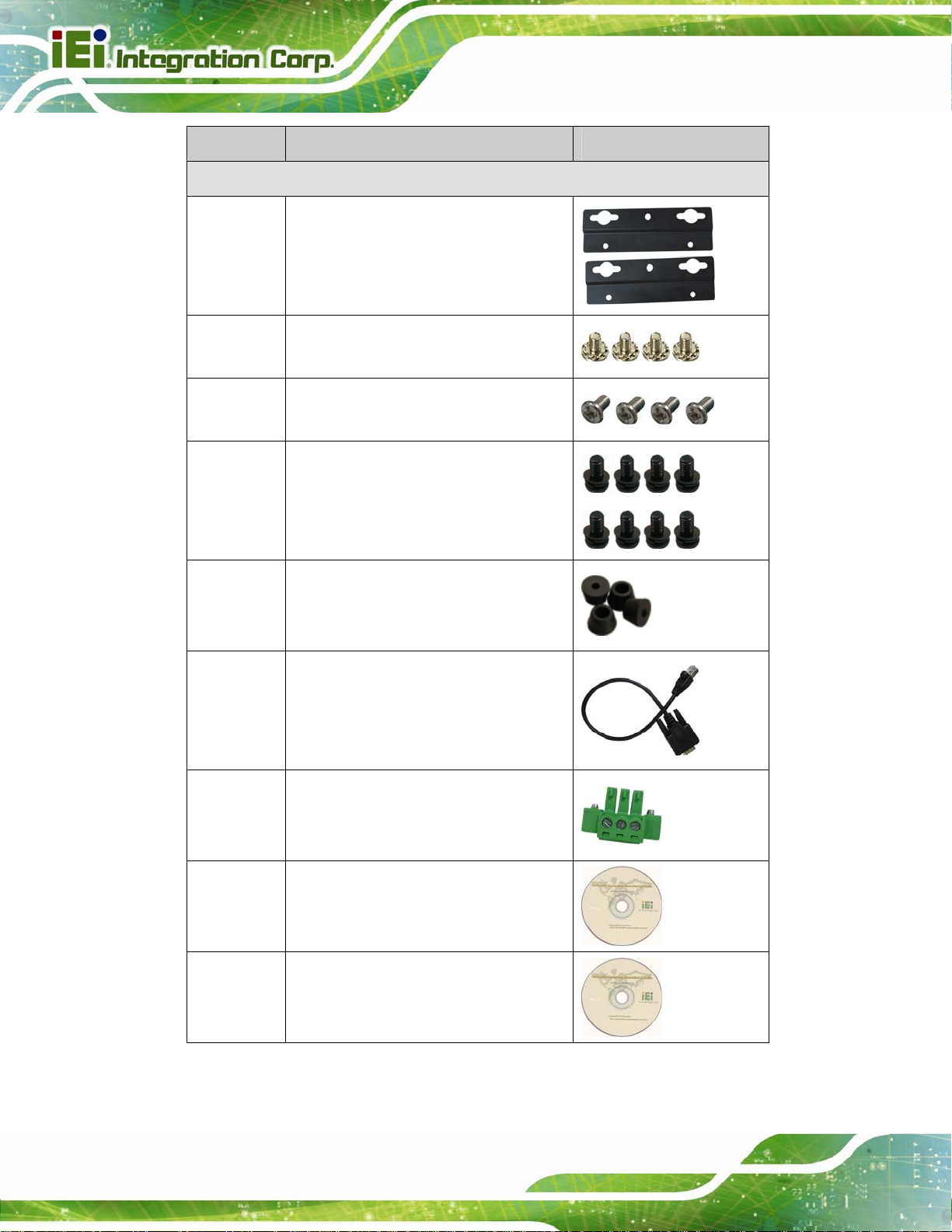
Quantity Item and Part Number Image
Standard
2 Mounting bracket
(P/N: 41020-0308C2-00-RS)
4 Mounting bracket screw
(P/N: 44033-040062-RS)
4 HDD screw
(P/N: 44043-030051-RS)
8 Rubber foot pad screw
TANK-800 Embedded System
(P/N: 44005-030061-RS)
4 Rubber foot pad
(P/N: 46007-001500-RS)
2 RJ-45 to DB-9 COM port cable
(P/N: 32005-000200-200-RS)
1 Pluggable DC-in terminal block
(P/N: 33502-000007-RS)
1 One Key Recovery CD
(P/N: 7B000-000724-RS)
Page 14
1 User manual and driver CD
(P/N: 7B000-000731-RS)
Page 27
TANK-800 Embedded System
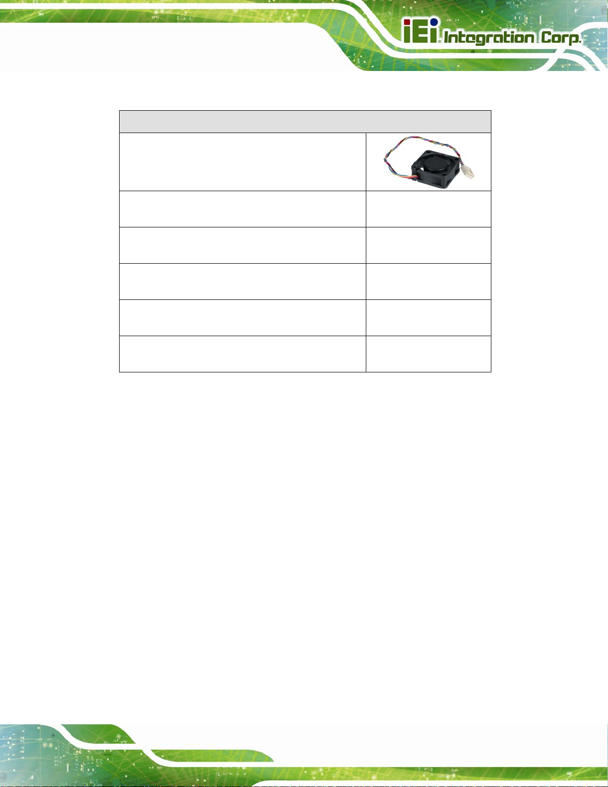
The following table lists the optional items that can be purchased separately.
Optional
System fan
(P/N: 31100-000333-RS)
OS: Win CE 6.0 (128MB CF Card)
(P/N: TANKCF-800-D525-CE060-128M-R10)
OS: Win XPE (2GB CF Card)
(P/N: TANKCF-800-D525-XPE-2G-R10)
OS: Win XPE (4GB CF Card)
(P/N: TANKCF-800-D525-XPE-4G-R10)
OS: Linux (2GB CF Card)
(P/N: TANKCF-800-D525-LNX-2G-R10)
OS: Win 7 Embedded (4GB CF Card)
(P/N: TANKCF-800-D525-WES7E-4G-R10)
Page 15
Page 28

TANK-800 Embedded System
Chapter
3
3 Installation
Page 16
Page 29

TANK-800 Embedded System
3.1 Installation Precautions
During installation, be aware of the precautions below:
Read the user manual: The user manual provides a complete description of
the TANK-800, installation instructions and configuration options.
DANGER! Disconnect Power: Power to the TANK-800 must be
disconnected during the installation process, or before any attempt is made to
access the rear panel. Electric shock and personal injury might occur if the
rear panel of the TANK-800 is opened while the power cord is still connected
to an electrical outlet.
Qualified Personnel: The TANK-800 must be installed and operated only by
trained and qualified personnel. Maintenance, upgrades, or repairs may only
be carried out by qualified personnel who are familiar with the associated
dangers.
Air Circulation: Make sure there is sufficient air circulation when installing the
TANK-800. The TANK-800’s cooling vents must not be obstructed by any
objects. Blocking the vents can cause overheating of the TANK-800. Leave at
least 5 cm of clearance around the TANK-800 to prevent overheating.
Grounding: The TANK-800 should be properly grounded. The voltage feeds
must not be overloaded. Adjust the cabling and provide external overcharge
protection per the electrical values indicated on the label attached to the back
of the TANK-800.
3.2 CF Card Installation
To install the CF card, please follow the steps below:
Step 1: Locate the CF card slot, and then loosen the thumbscrew (
Figure 1-2).
Page 17
Page 30
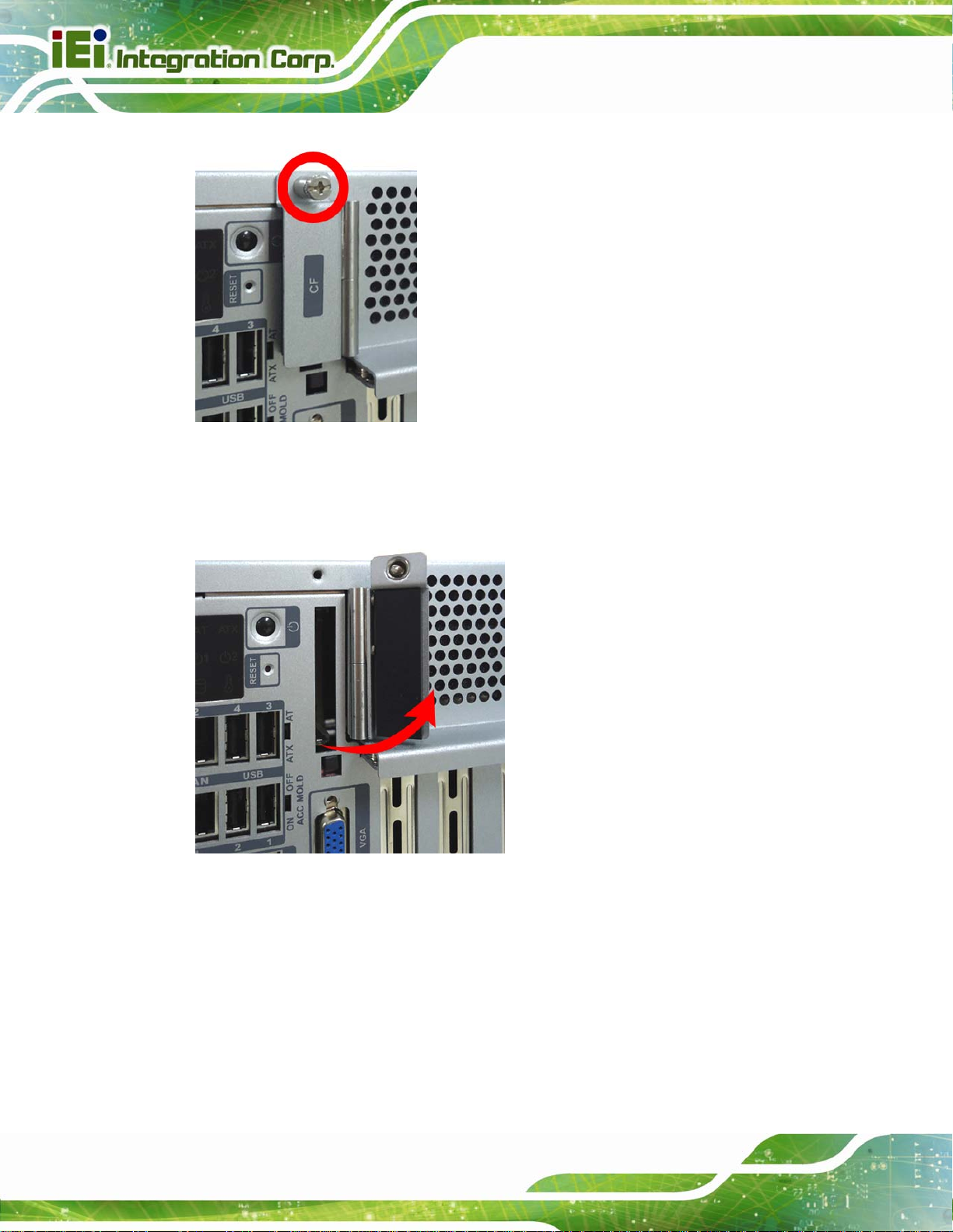
Figure 3-1: CF Card Slot
TANK-800 Embedded System
Step 2: Open the CF card slot cover (
Figure 3-2: CF Card Slot Cover
Figure 3-2).
Page 18
Page 31

TANK-800 Embedded System
Step 3: Correctly align the CF card with the socket and insert the CF card into the socket
Figure 3-3).
(
Figure 3-3: CF Card Installation
Step 4: Reinstall the cover.
3.3 Hard Disk Drive (HDD) Installation
To install the hard drive, please follow the steps below:
Step 1: Loosen the thumbscrew, slide the cover inwards (
cover up gently.
Figure 3-4), and then lift the
Page 19
Page 32

TANK-800 Embedded System
Figure 3-4: Unscrew the Cover
Step 2: Unplug the SATA signal and power cables connected to the TANK-800, and then
put the cover on a flat surface (
Figure 3-5).
Page 20
Figure 3-5: Remove the Cover from TANK-800
Page 33

TANK-800 Embedded System
Step 3: Attach the HDD to the HDD bracket, and then slide the HDD to connect the HDD
to the SATA connector (
Figure 3-6: HDD Installation
Figure 3-6).
Step 4: Secure the HDD with the HDD bracket by four retention screws (
Figure 3-7: HDD Retention Screws
Figure 3-7).
Page 21
Page 34

Step 5: Reconnect the SATA signal and power cables to the TANK-800.
Step 6: Reinstall the cover.
3.4 System Fan Installation
To install the optional system fan, please follow the steps below:
TANK-800 Embedded System
Step 1: Loosen the thumbscrew, slide the cover inwards (
cover up gently.
Step 2: Unplug the SATA signal and power cables connected to the TANK-800, and then
place the cover on a flat surface (
Step 3: Unscrew the four retention screws that secure the HDD bracket to the cover.
Figure 3-8). Remove the HDD bracket from the cover.
(
Figure 3-5).
Figure 3-4), and then lift the
Page 22
Figure 3-8: Remove the HDD Bracket from the Cover
Step 4: Unscrew the four retention screws that secure the fan bracket to the cover.
Figure 3-9). Remove the fan bracket from the cover.
(
Page 35

TANK-800 Embedded System
Figure 3-9: Remove the Fan Bracket from the Cover
Step 5: Remove the temporary retaining bracket (
Figure 3-10: Remove the Temporary Retaining Bracket
Step 6: Attach the system fan to the fan bracket and secure it by four retention screws
Figure 3-11).
(
Figure 3-10).
Page 23
Page 36

Figure 3-11: Secure the System Fan to the Fan Bracket
TANK-800 Embedded System
Step 7: Reinstall the fan bracket with the system fan installed (
Figure 3-12: Reinstall the Fan Bracket
Step 8: Reinstall the HDD bracket to the cover.
Step 9: Connect the system fan cable to the CPU_FAN1 connector on the motherboard
Figure 3-12).
Page 24
of TANK-800.
Step 10: Reconnect the SATA signal and power cables to the TANK-800.
Step 11: Reinstall the cover.
Page 37

TANK-800 Embedded System
3.5 Pluggable DC-In Terminal Block Installation
To install the pluggable DC-in terminal block, please follow the steps below:
Step 1: Locate the DC-in terminal block connector. The location of the connector is
shown in
Step 2: Align the pluggable DC-in terminal block with the DC-in terminal block connector
on the TANK-800.
Step 3: Once aligned, insert the pluggable DC-in terminal block into the DC-in terminal
block connector.
Step 4: Secure the pluggable DC-in terminal block to the external interface by tightening
the two retention screws on either side of the terminal block (
Figure 1-2.
Figure 3-13).
Figure 3-13: Pluggable DC-in Terminal Block Installation
Page 25
Page 38

TANK-800 Embedded System
3.6 Mounting the System with Mounting Brackets
To mount the embedded system onto a wall or some other surface using the two mounting
brackets, please follow the steps below.
Step 1: Turn the embedded system over or to the left side panel.
Step 2: Align the two retention screw holes in each bracket with the corresponding
retention screw holes on the bottom surface or the left side panel (
Bottom Surface
Left Side Panel
Figure 3-14).
Page 26
Figure 3-14: Mounting Bracket Retention Screws
Page 39

TANK-800 Embedded System
Step 3: Secure the brackets to the system by inserting two retention screws into each
bracket (
Step 4: Drill holes in the intended installation surface.
Step 5: Align the mounting holes in the sides of the mounting brackets with the predrilled
holes in the mounting surface.
Step 6: Insert four retention screws, two in each bracket, to secure the system to the
wall.
Figure 3-14).
3.7 External Peripheral Interface Connectors
The TANK-800 has the following connectors. Detailed descriptions of the connectors can
be found in the subsections below.
Audio
CompactFlash® Type II
DIO
Ethernet
Power button
Power input
Reset button
RS-232
RS-422/485
USB
VGA
Page 27
Page 40

3.7.1 ACC Mode Selection
The TANK-800 allows turning the ACC mode on or off. The setting can be made through
the ACC mode switch on the external peripheral interface panel as shown below.
TANK-800 Embedded System
Figure 3-15: ACC Mode Switch
3.7.2 AT/ATX Power Mode Selection
The TANK-800 supports AT and ATX power modes. The setting can be made through the
AT/ATX power mode switch on the external peripheral interface panel as shown below.
Page 28
Figure 3-16: AT/ATX Power Mode Switch
Page 41

TANK-800 Embedded System
3.7.3 Audio Connector
CN Label:
CN Type:
CN Location:
The audio jacks connect to external audio devices.
Line Out port (Green): Connects to a headphone or a speaker. With
multi-channel configurations, this port can also connect to front speakers.
Microphone (Pink): Connects a microphone.
Figure 3-17: Audio Connector
Line out and Mic
Audio jack
See Figure 1-2
3.7.4 CompactFlash® Type II
The TANK-800 has one CF Type II socket. The location of the socket is shown in
Figure 1-2. To install the CF card, refer to Section 3.2.
3.7.5 Digital Input/Output Connector
CN Label: DIO x 8
CN Type:
CN Location:
CN Pinouts:
The digital I/O connector provides programmable input and output for external devices.
The pinouts for the digital I/O connector are listed in the table below.
DB-9 female connector
Figure 1-2
See
Table 3-1 and Figure 3-18
See
Page 29
Page 42

Pin Description Pin Description
1 DIN0 6 DOUT2
2 DOUT0 7 DIN3
3 DIN1 8 DOUT3
4 DOUT1 9 VCC5
5 DIN2
TANK-800 Embedded System
Table 3-1: DIO Connector Pinouts
Figure 3-18: DIO Connector Pinout Location
3.7.6 LAN Connectors
CN Label: RJ45
CN Type:
CN Location:
CN Pinouts:
The LAN connectors allow connection to an external network.
RJ-45
Figure 1-2
See
Table 3-2
See
Page 30
Step 1: Locate the RJ-45 connectors. The locations of the RJ-45 connectors are
shown in
Figure 1-2.
Step 2: Align the connectors. Align the RJ-45 connector on the LAN cable with one of
the RJ-45 connectors on the TANK-800. See
Figure 3-19.
Page 43

TANK-800 Embedded System
Figure 3-19: LAN Connection
Step 3: Insert the LAN cable RJ-45 connector. Once aligned, gently insert the LAN
cable RJ-45 connector into the on-board RJ-45 connector.
Pin Description Pin Description
1 TRD1P0 5 TRD1P2
2 TRD1N0 6 TRD1N2
3. TRD1P1 7 TRD1P3
4. TRD1N1 8 TRD1N3
Table 3-2: LAN Pinouts
Figure 3-20: RJ-45 Ethernet Connector
The RJ-45 Ethernet connector has two status LEDs, one green and one yellow. The green
LED indicates activity on the port and the yellow LED indicates the port is linked. See
Table 3-3.
Page 31
Page 44

Activity/Link LED Speed LED
TANK-800 Embedded System
STATUS
Off No link Off 10 Mbps connection
Yellow Linked Green 100 Mbps connection
Blinking TX/RX activity Orange 1 Gbps connection
Table 3-3: RJ-45 Ethernet Connector LEDs
DESCRIPTION STATUS DESCRIPTION
3.7.7 Power Input, 3-pin Terminal Block
CN Label: POWER 1
CN Type:
CN Location:
CN Pinouts:
Connect the leads of a 9V~36V DC power supply into the terminal block. Make sure that
the power and ground wires are attached to the correct sockets of the connector.
3-pin terminal block
Figure 1-2
See
Figure 3-21
See
Figure 3-21: 3-pin Terminal Block Pinout Location
3.7.8 Power Input, 4-pin DIN Connector
CN Label: POWER 2
4-pin DIN connector
Figure 1-2
See
Table 3-4 and Figure 3-22
See
Page 32
CN Type:
CN Location:
CN Pinouts:
The power connector connects to the 10.5V~36V DC power adapter.
Page 45

TANK-800 Embedded System
Figure 3-22: Power Input Connector
Pin Description Pin Description
1 +12V 3 +12V
2 GND 4 GND
Table 3-4: Power Input Pinouts
3.7.9 RJ-45 RS-422/485 Serial Ports
CN Label: RS422/485
CN Type:
CN Location:
CN Pinouts:
RS-422/485 serial port devices can be attached to the RJ-45 RS-422/485 serial ports on
the rear panel.
Step 1: Locate the RJ-45 RS-422/RS485 connectors. The locations of the RJ-45
RJ-45
Figure 1-2
See
Table 3-5 and Figure 3-24
See
RS-422/RS-485 connectors are shown in
Step 2: Insert the RJ-45 connector. Insert the RJ-45 connector on the RJ-45 to DB-9
COM port cable to one of the RJ-45 RS-422/485 connectors on the TANK-800.
Figure 3-23.
See
Figure 1-2.
Page 33
Page 46

TANK-800 Embedded System
Figure 3-23: RJ-45 RS-422/485 Serial Device Connection
Step 3: Insert the serial connector. Insert the DB-9 connector of a serial device into
the DB-9 connector on the RJ-45 to DB-9 COM port cable.
Step 4: Secure the connector. Secure the serial device connector to the external
interface by tightening the two retention screws on either side of the connector.
Figure 3-24: RJ-45 RS-422/485 Serial Port Pinout Location
Pin Description (RS-422) Description (RS-485)
1 N/A N/A
2 ITXD422# ITXD485#
3 N/A N/A
4 ITXD422+ ITXD485#
5 GND GND
6 IRXD422# N/A
7 N/A N/A
8 IRXD422+ N/A
Page 34
Table 3-5: RJ-45 RS-422/485 Serial Port Pinouts
Page 47

TANK-800 Embedded System
Figure 3-25: DB-9 Connector Pinout Location
Pin Description (RS-422) Description (RS-485)
1 IRXD422+ N/A
2 IRXD422# N/A
3 ITXD422+ ITXD485+
4 ITXD422# ITXD485#
5 GND GND
6 N/A N/A
7 N/A N/A
8 N/A N/A
9 N/A N/A
Table 3-6: DB-9 Connector Pinouts
3.7.10 RS-232 Serial Port Connectors
CN Label:
COM1, COM2, COM3 and COM4
CN Type:
CN Location:
CN Pinouts:
DB-9 connectors
Figure 1-2
See
Table 3-7 and Figure 3-27
See
RS-232 serial port devices can be attached to the DB-9 ports on the rear panel.
Step 1: Locate the DB-9 connector. The locations of the DB-9 connectors are shown
Figure 1-2.
in
Step 2: Insert the serial connector. Insert the DB-9 connector of a serial device into
the DB-9 connector on the external peripheral interface. See
Figure 3-26.
Page 35
Page 48

TANK-800 Embedded System
Figure 3-26: Serial Device Connector
Step 3: Secure the connector. Secure the serial device connector to the external
interface by tightening the two retention screws on either side of the connector.
Pin Description Pin Description
1 DCD 6 DSR
2 RX 7 RTS
3 TX 8 CTS
4 DTR 9 RI
5 GND
Table 3-7: Serial Port Pinouts
Page 36
Figure 3-27: Serial Port Pinout Location
Page 49

TANK-800 Embedded System
3.7.11 USB Connectors
CN Label: USB
CN Type:
CN Location:
CN Pinouts:
The USB ports are for connecting USB peripheral devices to the system.
Step 1: Locate the USB connectors. The locations of the USB connectors are shown
Figure 1-2.
in
Step 2: Align the connectors. Align the USB device connector with one of the
connectors. See
USB port
Figure 1-2
See
Table 3-8
See
Figure 3-28.
Figure 3-28: USB Device Connection
Step 3: Insert the device connector. Once aligned, gently insert the USB device
connector into the on-board connector.
Page 37
Page 50

Pin Description Pin Description
1 VCC 5 VCC
2 DATA- 6 DATA3 DATA+ 7 DATA+
4 GROUND 8 GROUND
Table 3-8: USB Port Pinouts
3.7.12 VGA Connector
CN Label: VGA
TANK-800 Embedded System
CN Type:
CN Location:
CN Pinouts:
15-pin Female
Figure 1-2
See
Figure 3-30 and Table 3-9
See
The VGA connector connects to a monitor that accepts VGA video input.
Step 1: Locate the female DB-15 connector. The location of the female DB-15
connector is shown in
Figure 1-2.
Step 2: Align the VGA connector. Align the male DB-15 connector on the VGA screen
cable with the female DB-15 connector on the external peripheral interface.
Step 3: Insert the VGA connector. Once the connectors are properly aligned with,
insert the male connector from the VGA screen into the female connector on the
TANK-800. See
Figure 3-29.
Page 38
Page 51

TANK-800 Embedded System
Figure 3-29: VGA Connector
Step 4: Secure the connector. Secure the DB-15 VGA connector from the VGA
monitor to the external interface by tightening the two retention screws on either
side of the connector.
Figure 3-30: VGA Connector
Pin Description Pin Description
1 RED 2 GREEN
3 BLUE 4 NC
5 GND 6 GND
7 GND 8 GND
9 VCC / NC 10 GND
11 NC 12 DDC DAT
13 HSYNC 14 VSYNC
15 DDCCLK
Table 3-9: VGA Connector Pinouts
Page 39
Page 52

3.8 Powering On/Off the System
WARNING:
Make sure a power supply with the correct input voltage is being fed into
the system. Incorrect voltages applied to the system may cause damage to
the internal electronic components and may also cause injury to the user.
Power on the system: press the power button for 3 seconds
Power off the system: press the power button for 6 seconds
TANK-800 Embedded System
Figure 3-31: Power Button
3.9 Redundant Power
The TANK-800 is a system that supports redundant power. The redundant power input
increases the reliability of the system and prevents data loss and system corruption from
sudden power failure. The system can instantly and uninterruptedly switch to the second
power input when the main power is unavailable or in low voltage capacity.
There are two power connectors on the rear panel. Power 1 connector is a 3-pin terminal
block that supports ACC On signal. Power 2 connector is a DIN connector that can directly
connect to a power adapter. The supported power input voltages are:
Page 40
Page 53

TANK-800 Embedded System
Power 1 (terminal block): 9 V (+/-0.3 V) ~ 36 V
Power 2 (DC jack): 10.5 V (+/-0.3 V) ~ 36 V
Figure 3-32: Power Connectors
When the system is in ACC On mode, the main power input is from Power 1 connector;
when the system is in ACC Off mode, the main power input is from Power 2 connector. The
ACC on/off mode is selected by the ACC mode switch on the rear panel (
The following sections describe how the redundant power works in ACC On mode and
ACC Off mode.
Figure 3-15).
3.9.1 ACC ON
NOTE:
In ACC On mode, the Power 1 connector must connect to ACC on
signal to be able to control the system power.
The ACC On mode is designed for vehicle applications. When the TANK-800 is in ACC
On mode, the main power input is Power 1 connector and the backup power is from Power
2 connector.
Page 41
Page 54

3.9.1.1 Boot-up
When both power connectors are connected to power source with over 9 V power input,
the two power LEDs on the front panel remain off until the ACC ON signal jump from
low to high. The user can choose to use AT power mode or ATX power mode to control
the system. The following flow diagrams show the boot-up process and the LED status in
AT and ATX power modes.
Figure 3-33: ACC On: AT Mode
TANK-800 Embedded System
Figure 3-34: ACC On: ATX Mode
3.9.1.2 Switch to Backup Power
During the operation, the system power will switch from Power 1 to Power 2 automatically
when the following situations occur:
Power 1 < 9V and Power 2 > 10.5V
Power 1 > 9V, but the ACC ON signal jump from high to low
Power 1 is unplugged and Power 2 > 10.5V
The following flow diagram shows how the power is switched between Power 1 and
Power 2 and their LED statuses.
Page 42
Page 55

TANK-800 Embedded System
Figure 3-35: ACC On: Switch Between PWR1 and PWR2
3.9.1.3 Shutdown
The system will shutdown in the following situations:
Power 1 < 9V and Power 2 < 10.5V
Power 1 > 9V, Power 2 < 10.5V and ACC ON signal jump from high to low
Press Power button for 6 seconds
The following flow diagram shows the system shutdown process and the LED statuses.
Figure 3-36: ACC On: Shutdown
NOTE:
To turn on the system in the ATX power mode, press the Power button
for three seconds. Press the Power button for six seconds to turn off
the system.
Page 43
Page 56

3.9.2 ACC OFF
When the TANK-800 is in ACC Off mode, the main power input is Power 2 connector and
the backup power is from Power 1 connector.
3.9.2.1 Boot-up
When both power connectors are connected to power source with over 9 V power input,
the two power LEDs on the front panel turn on. The user can choose to use AT power
mode or ATX power mode to control the system. The following flow diagrams show the
boot-up process and the LED status in AT and ATX power modes.
TANK-800 Embedded System
Figure 3-37: ACC Off: AT Mode
Figure 3-38: ACC Off: ATX Mode
3.9.2.2 Switch to Backup Power
During the operation, the system power will switch from Power 2 to Power 1 automatically
when the following situations occur:
Power 2 < 10.5V and Power 1 > 9V
Power 2 is unplugged and Power 1 > 9V
Page 44
The following flow diagram shows how the power is switched between Power 2 and
Power 1 and their LED statuses.
Page 57

TANK-800 Embedded System
Figure 3-39: ACC Off: Switch Between PWR1 and PWR2
3.9.2.3 Shutdown
The system will shutdown in the following situations:
Power 2 < 10.5V and Power 1 < 9V
Press Power buttons for 6 seconds
The following flow diagram shows the system shutdown process and the LED statuses.
Figure 3-40: ACC Off: Shutdown
NOTE:
The power LED turns off when the power cable is unplugged from the
system.
Page 45
Page 58

TANK-800 Embedded System
Chapter
4
4 BIOS
Page 46
Page 59

TANK-800 Embedded System
4.1 Introduction
The BIOS is programmed onto the BIOS chip. The BIOS setup program allows changes to
certain system settings. This chapter outlines the options that can be changed.
4.1.1 Starting Setup
The UEFI BIOS is activated when the computer is turned on. The setup program can be
activated in one of two ways.
1. Press the DEL or F2 key as soon as the system is turned on or
2. Press the DEL or F2 key when the “Press DEL or F2 to enter SETUP”
message appears on the screen.
If the message disappears before the DEL or F2 key is pressed, restart the computer and
try again.
4.1.2 Using Setup
Use the arrow keys to highlight items, press ENTER to select, use the PageUp and
PageDown keys to change entries, press F1 for help and press E
keys are shown in.
Key Function
Up arrow Move to previous item
Down arrow Move to next item
Left arrow Move to the item on the left hand side
Right arrow Move to the item on the right hand side
+ Increase the numeric value or make changes
- Decrease the numeric value or make changes
Page Up key Increase the numeric value or make changes
Page Dn key Decrease the numeric value or make changes
SC to quit. Navigation
Page 47
Page 60

Key Function
Esc key Main Menu – Quit and not save changes into CMOS
F1 General help, only for Status Page Setup Menu and Option
F2 Previous values
F3 Load optimized defaults
F4 Save changes and Exit BIOS
Table 4-1: BIOS Navigation Keys
4.1.3 Getting Help
TANK-800 Embedded System
Status Page Setup Menu and Option Page Setup Menu --
Exit current page and return to Main Menu
Page Setup Menu
When F1 is pressed a small help window describing the appropriate keys to use and the
possible selections for the highlighted item appears. To exit the Help Window press E
the F1 key again.
4.1.4 Unable to Reboot After Configuration Changes
If the computer cannot boot after changes to the system configuration is made, CMOS
defaults. Use the jumper described in Chapter 3.
4.1.5 BIOS Menu Bar
The menu bar on top of the BIOS screen has the following main items:
Main – Changes the basic system configuration.
Advanced – Changes the advanced system settings.
Chipset – Changes the chipset settings.
Boot – Changes the system boot configuration.
Security – Sets User and Supervisor Passwords.
SC or
Page 48
Save & Exit – Selects exit options and loads default settings.
The following sections completely describe the configuration options found in the menu
items at the top of the BIOS screen and listed above.
Page 61

TANK-800 Embedded System
4.2 Main
The Main BIOS menu (BIOS Menu 1) appears when the BIOS Setup program is entered.
The Main menu gives an overview of the basic system information.
Aptio Setup Utility – Copyright (C) 2011 American Megatrends, Inc.
Main Advanced Chipset Boot Security Save & Exit
BIOS Information
BIOS Vendor American Megatrends
Core Version 4.6.4.0 0.20
Compliency UEFI 2.0
Project Version SA37AR10.ROM
Build Date and Time 08/09/2011 11:53:40
System Date [Tue 08/09/2011]
System Time [15:10:27]
Access Level Administrator
Version 2.11.1210. Copyright (C) 2011 American Megatrends, Inc.
Set the Date. Use Tab to
switch between Data
elements.
----------------------
ÅÆ
: Select Screen
↑ ↓: Select Item
Enter Select
+ - Change Opt.
F1 General Help
F2 Previous Values
F3 Optimized Defaults
F4 Save & Exit
ESC Exit
BIOS Menu 1: Main
Î Sy stem Overview
The BIOS Information lists a brief summary of the BIOS. The fields in BIOS Information
cannot be changed. The items shown in the system overview include:
BIOS Vendor: Installed BIOS vendor
Core Version: Current BIOS version
Project Version: the board version
Build Date and Time: Date and time the current BIOS version was made
The System Overview field also has two user configurable fields:
Î Sy stem Date [xx/xx/xx]
Use the System Date option to set the system date. Manually enter the day, month and
year.
Page 49
Page 62

Î Sy stem Time [xx:xx:xx]
Use the System Time option to set the system time. Manually enter the hours, minutes
and seconds.
4.3 Advanced
Use the Advanced menu (BIOS Menu 2) to configure the CPU and peripheral devices
through the following sub-menus:
WARNING!
Setting the wrong values in the sections below may cause the system
to malfunction. Make sure that the settings made are compatible with
the hardware.
TANK-800 Embedded System
Aptio Setup Utility – Copyright (C) 2011 American Megatrends, Inc.
Main Advanced Chipset Boot Security Save & Exit
> ACPI Settings
> CPU Configuration
> IDE Configuration
> USB Configuration
> Super IO Configuration
> H/M Monitor
> Serial Port Console Redirection
> iEi Feature
Version 2.11.1210. Copyright (C) 2011 American Megatrends, Inc.
BIOS Menu 2: Advanced
System ACPI Parameters
----------------------
ÅÆ
↑ ↓: Select Item
Enter Select
+ - Change Opt.
F1 General Help
F2 Previous Values
F3 Optimized Defaults
F4 Save & Exit
ESC Exit
: Select Screen
Page 50
Page 63

S
TANK-800 Embedded System
4.3.1 ACPI Settings
The ACPI Settings menu (BIOS Menu 3) configures the Advanced Configuration and
Power Interface (ACPI) options.
Aptio Setup Utility – Copyright (C) 2011 American Megatrends, Inc.
Advanced
ACPI Sleep State [S1 (CPU Stop Clock)]
Version 2.11.1210. Copyright (C) 2011 American Megatrends, Inc.
elect the highest ACPI
sleep state the system
will enter when the
SUSPEND button is
pressed.
----------------------
ÅÆ
: Select Screen
↑ ↓: Select Item
Enter Select
+ - Change Opt.
F1 General Help
F2 Previous Values
F3 Optimized Defaults
F4 Save & Exit
ESC Exit
BIOS Menu 3: ACPI Configuration
Î ACPI Sleep State [S1 (CPU Stop Clock)]
Use the ACPI Sleep State option to specify the sleep state the system enters when it is
not being used.
Î
Suspend Disabled
Î
S1 (CPU Stop
Clock)
Î
S3 (Suspend to
RAM)
DEFAULT
The system enters S1(POS) sleep state. The
system appears off. The CPU is stopped; RAM is
refreshed; the system is running in a low power
mode.
The caches are flushed and the CPU is powered
off. Power to the RAM is maintained. The
computer returns slower to a working state, but
more power is saved.
Page 51
Page 64

a
T
TANK-800 Embedded System
4.3.2 CPU Configuration
Use the CPU Configuration menu (BIOS Menu 4) to view detailed CPU specifications
and configure the CPU.
Aptio Setup Utility – Copyright (C) 2011 American Megatrends, Inc.
Advanced
CPU Configuration
Processor Type Intel(R) Atom(TM)
CPU D525 @ 1.80GHz
EMT64 Supported
Processor Speed 1800 MHz
System Bus Speed 800 MHz
Ratio Status 9
Actual Ratio 9
Processor Stepping 106CA
Microcode Revision 263
L1 Cache RAM 2x56 K
L2 Cache RAM 2x512 K
Processor Core Dual
Hyper-Threading Supported
Hyper-Threading [Enabled]
Version 2.11.1210. Copyright (C) 2011 American Megatrends, Inc.
Enabled for Windows XP
nd Linux (OS optimized
for Hyper-Threading
echnology) and Disabled
for other OS (OS not
optimized for
Hyper-Threading
Technology).
----------------------
ÅÆ
: Select Screen
↑ ↓: Select Item
Enter Select
+ - Change Opt.
F1 General Help
F2 Previous Values
F3 Optimized Defaults
F4 Save & Exit
ESC Exit
Page 52
BIOS Menu 4: CPU Configuration
The CPU Configuration menu (
Processor Type: Lists the brand name of the CPU being used
EMT64: Indicates if the EM64T is supported by the CPU.
Processor Speed: Lists the CPU processing speed
System Bus Speed: Lists the system bus
Ratio Status: List the maximum FSB divisor
Actual Ratio: Lists current FSB divisor
Processor Stepping: Lists the CPU processing stepping
Microcode Revision: Lists the microcode revision
L1 Cache RAM: Lists the CPU L1 cache size
L2 Cache RAM: Lists the CPU L2 cache size
Processor Core: Lists the number of the processor core
BIOS Menu 4) lists the following CPU details:
Page 65

TANK-800 Embedded System
Hyper-Threading: Indicates if the Intel Hyper-Threading Technology is
supported by the CPU.
Î Hyper-Threading [Enabled]
Use the Hyper-Threading BIOS option to enable or disable the Intel Hyper-Threading
Technology.
Î
Disabled
Î
Enabled DEFAULT
Disables the Intel Hyper-Threading Technology.
Enables the Intel Hyper-Threading Technology.
4.3.3 IDE Configuration
Use the IDE Configuration menu (BIOS Menu 5) to change and/or set the configuration
of the SATA devices installed in the system.
Aptio Setup Utility – Copyright (C) 2011 American Megatrends, Inc.
Advanced
PATA Master Not Present
PATA Slave Not Present
SATA Port0 Not Present
SATA Port1 Not Present
SATA Port2 Not Present
SATA Port3 Not Present
ATA/IDE Configuration [Enhanced]
Configure SATA as [IDE]
Version 2.11.1210. Copyright (C) 2011 American Megatrends, Inc.
Select ATA or IDE
Configuration.
---------------------
ÅÆ
: Select Screen
↑ ↓: Select Item
Enter Select
+ - Change Opt.
F1 General Help
F2 Previous Values
F3 Optimized Defaults
F4 Save & Exit
ESC Exit
BIOS Menu 5: IDE Configuration
Î ATA/IDE Configuration [Enhanced]
Use the ATA/IDE Configuration option to configure the ATA/IDE controller.
Î
Disabled
Disables the on-board ATA/IDE controller.
Page 53
Page 66

TANK-800 Embedded System
Î
Compatible
Î
Enhanced DEFAULT
Î Configure SATA as [IDE]
Use the Configure SATA as option to configure SATA devices as normal IDE devices.
Î
IDE DEFAULT
Î
AHCI
Configures SATA devices as normal IDE device.
Configures SATA devices as AHCI device.
Configures the on-board ATA/IDE controller to be in
compatible mode. In this mode, a SATA channel will
replace one of the IDE channels. This mode supports
up to 4 storage devices.
Configures the on-board ATA/IDE controller to be in
Enhanced mode. In this mode, IDE channels and SATA
channels are separated. This mode supports up to 6
storage devices. Some legacy OS do not support this
mode.
Page 54
Page 67

d
TANK-800 Embedded System
4.3.4 USB Configuration
Use the USB Configuration menu (BIOS Menu 6) to read USB configuration information
and configure the USB settings.
Aptio Setup Utility – Copyright (C) 2011 American Megatrends, Inc.
Advanced
USB Configuration
USB Devices:
1 Keyboard
Legacy USB Support [Enabled]
Version 2.11.1210. Copyright (C) 2011 American Megatrends, Inc.
Enables Legacy USB
support. AUTO option
isables legacy support
if no USB devices are
connected. DISABLE
option will keep USB
devices available only
for EFI applications.
---------------------
ÅÆ
: Select Screen
↑ ↓: Select Item
Enter Select
+ - Change Opt.
F1 General Help
F2 Previous Values
F3 Optimized Defaults
F4 Save & Exit
ESC Exit
BIOS Menu 6: USB Configuration
Î USB Devices
The USB Devices field lists the USB devices that are enabled on the system
Î Legacy USB Support [En abled]
Use the Legacy USB Support BIOS option to enable USB mouse and USB keyboard
support. Normally if this option is not enabled, any attached USB mouse or USB keyboard
does not become available until a USB compatible operating system is fully booted with all
USB drivers loaded. When this option is enabled, any attached USB mouse or USB
keyboard can control the system even when there is no USB driver loaded onto the
system.
Î
Enabled DEFAULT
Legacy USB support enabled
Page 55
Page 68

S
TANK-800 Embedded System
Î
Disabled
Î
Auto
Legacy USB support disabled
Legacy USB support disabled if no USB devices are
connected
4.3.5 Super IO Configuration
Use the Super IO Configuration menu (BIOS Menu 7) to set or change the
configurations for the serial ports.
Aptio Setup Utility – Copyright (C) 2011 American Megatrends, Inc.
Advanced
Super IO Configuration
> Serial Port 1 Configuration
> Serial Port 2 Configuration
> Serial Port 3 Configuration
> Serial Port 4 Configuration
> Serial Port 5 Configuration
> Serial Port 6 Configuration
Version 2.11.1210. Copyright (C) 2011 American Megatrends, Inc.
et Parameters of Serial
Port 1 (COMA)
---------------------
ÅÆ
: Select Screen
↑ ↓: Select Item
Enter Select
+ - Change Opt.
F1 General Help
F2 Previous Values
F3 Optimized Defaults
F4 Save & Exit
ESC Exit
Page 56
BIOS Menu 7: Super IO Configuration
Page 69

E
TANK-800 Embedded System
4.3.5.1 Serial Port n Configuration
Use the Serial Port n Configuration menu (BIOS Menu 8) to configure the serial port n.
Aptio Setup Utility – Copyright (C) 2011 American Megatrends, Inc.
Advanced
Serial Port n Configuration
Serial Port [Enabled]
Device Settings IO=3F8h; IRQ=4
Change Settings [Auto]
Version 2.11.1210. Copyright (C) 2011 American Megatrends, Inc.
nable or Disable Serial
Port (COM)
---------------------
ÅÆ
: Select Screen
↑ ↓: Select Item
Enter Select
+ - Change Opt.
F1 General Help
F2 Previous Values
F3 Optimized Defaults
F4 Save & Exit
ESC Exit
BIOS Menu 8: Serial Port n Configuration Menu
4.3.5.1.1 Serial Port 1 Configuration
Î Serial Port [Enabled]
Use the Serial Port option to enable or disable the serial port.
Î
Disabled
Î
Enabled DEFAULT
Î Change Settings [Auto]
Use the Change Settings option to change the serial port IO port address and interrupt
address.
Î
Auto DEFAULT
Disable the serial port
Enable the serial port
The serial port IO port address and interrupt address
are automatically detected.
Î
IO=3F8h;
IRQ=4
Serial Port I/O port address is 3F8h and the interrupt
address is IRQ4
Page 57
Page 70

TANK-800 Embedded System
Î
IO=3F8h;
IRQ=3, 4
Î
IO=2F8h;
IRQ=3, 4
Î
IO=2C0h;
IRQ=3, 4
Î
IO=2C8h;
IRQ=3, 4
4.3.5.1.2 Serial Port 2 Configuration
Î Serial Port [Enabled]
Use the Serial Port option to enable or disable the serial port.
Î
Disabled
Serial Port I/O port address is 3F8h and the interrupt
address is IRQ3, 4
Serial Port I/O port address is 2F8h and the interrupt
address is IRQ3, 4
Serial Port I/O port address is 2C0h and the interrupt
address is IRQ3, 4
Serial Port I/O port address is 2C8h and the interrupt
address is IRQ3, 4
Disable the serial port
Î
Enabled DEFAULT
Î Change Settings [Auto]
Use the Change Settings option to change the serial port IO port address and interrupt
address.
Î
Auto DEFAULT
Î
Î
Î
Î
IO=2F8h;
IRQ=3
IO=3F8h;
IRQ=3, 4
IO=2F8h;
IRQ=3, 4
IO=2C0h;
Enable the serial port
The serial port IO port address and interrupt address
are automatically detected.
Serial Port I/O port address is 2F8h and the interrupt
address is IRQ3
Serial Port I/O port address is 3F8h and the interrupt
address is IRQ3, 4
Serial Port I/O port address is 2F8h and the interrupt
address is IRQ3, 4
Serial Port I/O port address is 2C0h and the interrupt
Page 58
IRQ=3, 4
address is IRQ3, 4
Page 71

TANK-800 Embedded System
Î
IO=2C8h;
IRQ=3, 4
4.3.5.1.3 Serial Port 3 Configuration
Î Serial Port [Enabled]
Use the Serial Port option to enable or disable the serial port.
Î
Disabled
Î
Enabled DEFAULT
Î Change Settings [Auto]
Use the Change Settings option to change the serial port IO port address and interrupt
address.
Î
Auto DEFAULT
Serial Port I/O port address is 2C8h and the interrupt
address is IRQ3, 4
Disable the serial port
Enable the serial port
The serial port IO port address and interrupt address
are automatically detected.
Î
Î
Î
Î
Î
IO=3E8h;
IRQ=10
IO=3E8h;
IRQ=10, 11
IO=2E8h;
IRQ=10, 11
IO=2D0h;
IRQ=10, 11
IO=2D8h;
IRQ=10, 11
Serial Port I/O port address is 3E8h and the interrupt
address is IRQ10
Serial Port I/O port address is 3E8h and the interrupt
address is IRQ10, 11
Serial Port I/O port address is 2E8h and the interrupt
address is IRQ10, 11
Serial Port I/O port address is 2D0h and the interrupt
address is IRQ10, 11
Serial Port I/O port address is 2D8h and the interrupt
address is IRQ10, 11
Page 59
Page 72

4.3.5.1.4 Serial Port 4 Configuration
Î Serial Port [Enabled]
Use the Serial Port option to enable or disable the serial port.
TANK-800 Embedded System
Î
Disabled
Î
Enabled DEFAULT
Î Change Settings [Auto]
Use the Change Settings option to change the serial port IO port address and interrupt
address.
Î
Auto DEFAULT
Î
Î
Î
IO=2E8h;
IRQ=10
IO=3E8h;
IRQ=10, 11
IO=2E8h;
IRQ=10, 11
Disable the serial port
Enable the serial port
The serial port IO port address and interrupt address
are automatically detected.
Serial Port I/O port address is 2E8h and the interrupt
address is IRQ10
Serial Port I/O port address is 3E8h and the interrupt
address is IRQ10, 11
Serial Port I/O port address is 2E8h and the interrupt
address is IRQ10, 11
Î
IO=2D0h;
IRQ=10, 11
Î
IO=2D8h;
IRQ=10, 11
Î Device Mode [RS42 2/485]
Use the Device Mode option to enable or disable the serial port.
Î
Normal
Î
RS422/485 DEFAULT
Page 60
Serial Port I/O port address is 2D0h and the interrupt
address is IRQ10, 11
Serial Port I/O port address is 2D8h and the interrupt
address is IRQ10, 11
Sets the serial port mode to normal.
Enables serial port RS-422/485 support.
Page 73

TANK-800 Embedded System
4.3.5.1.5 Serial Port 5 Configuration
Î Serial Port [Enabled]
Use the Serial Port option to enable or disable the serial port.
Î
Disabled
Î
Enabled DEFAULT
Î Change Settings [Auto]
Use the Change Settings option to change the serial port IO port address and interrupt
address.
Î
Auto DEFAULT
Î
Î
Î
IO=2C0h;
IRQ=10
IO=2C0h;
IRQ=10, 11
IO=2C8h;
IRQ=10, 11
Disable the serial port
Enable the serial port
The serial port IO port address and interrupt address
are automatically detected.
Serial Port I/O port address is 2C0h and the interrupt
address is IRQ10
Serial Port I/O port address is 2C0h and the interrupt
address is IRQ10, 11
Serial Port I/O port address is 2C8h and the interrupt
address is IRQ10, 11
Î
IO=2D0h;
IRQ=10, 11
Î
IO=2D8h;
IRQ=10, 11
Î
IO=2E0h;
IRQ=10, 11
4.3.5.1.6 Serial Port 6 Configuration
Î Serial Port [Enabled]
Use the Serial Port option to enable or disable the serial port.
Serial Port I/O port address is 2D0h and the interrupt
address is IRQ10, 11
Serial Port I/O port address is 2D8h and the interrupt
address is IRQ10, 11
Serial Port I/O port address is 2E0h and the interrupt
address is IRQ10, 11
Page 61
Page 74

TANK-800 Embedded System
Î
Disabled
Î
Enabled DEFAULT
Î Change Settings [Auto]
Use the Change Settings option to change the serial port IO port address and interrupt
address.
Î
Auto DEFAULT
Î
Î
Î
IO=2E0h;
IRQ=10
IO=2C0h;
IRQ=10, 11
IO=2C8h;
IRQ=10, 11
Disable the serial port
Enable the serial port
The serial port IO port address and interrupt address
are automatically detected.
Serial Port I/O port address is 2E0h and the interrupt
address is IRQ10
Serial Port I/O port address is 2C0h and the interrupt
address is IRQ10, 11
Serial Port I/O port address is 2C8h and the interrupt
address is IRQ10, 11
Î
Î
Î
IO=2D0h;
IRQ=10, 11
IO=2D8h;
IRQ=10, 11
IO=2E0h;
IRQ=10, 11
Serial Port I/O port address is 2D0h and the interrupt
address is IRQ10, 11
Serial Port I/O port address is 2D8h and the interrupt
address is IRQ10, 11
Serial Port I/O port address is 2E0h and the interrupt
address is IRQ10, 11
Page 62
Page 75

TANK-800 Embedded System
4.3.6 H/W Monitor
The H/W Monitor menu (BIOS Menu 9) shows the operating temperature, fan speeds
and system voltages.
Aptio Setup Utility – Copyright (C) 2011 American Megatrends, Inc.
Advanced
PC Health Status
CPU Temperature :+45 C
Accuracy: 1. (-5~+10) degree around 100 degree.
2. (-10~+15) degree around 50 degree.
SYS Temperature :+40 C
CPU FAN Speed :N/A
VCC3V :+3.312 V
V_Core :+1.152 V
V1.05S :+1.005 V
Vcc3S :+3.312 V
Vcc5V :+5.312 V
VSB3V :+3.328 V
VBAT :+3.216 V
Version 2.11.1210. Copyright (C) 2011 American Megatrends, Inc.
---------------------
ÅÆ
: Select Screen
↑ ↓: Select Item
Enter Select
+ - Change Opt.
F1 General Help
F2 Previous Values
F3 Optimized Defaults
F4 Save & Exit
ESC Exit
BIOS Menu 9: H/W Monitor
Î PC Health Status
The following system parameters and values are shown. The system parameters that are
monitored are:
System Temperatures:
o CPU Temperature
o System Temperature
Fan Speeds:
o CPU Fan Speed
Voltages:
o VCC3V
o Vcore
o Vcc
o V1.05S
Page 63
Page 76

TANK-800 Embedded System
o Vcc3S
o Vcc5V
o VSB3V
o VBAT
4.3.7 Serial Port Console Redirection
The Serial Port Console Redirection menu (BIOS Menu 10) allows the console
redirection options to be configured. Console redirection allows users to maintain a
system remotely by re-directing keyboard input and text output through the serial port.
Aptio Setup Utility – Copyright (C) 2011 American Megatrends, Inc.
Advanced
COM1
Console Redirection [Disabled]
> Console Redirection Settings
COM2
Console Redirection [Disabled]
> Console Redirection Settings
COM3
Console Redirection [Disabled]
> Console Redirection Settings
COM4
Console Redirection [Disabled]
> Console Redirection Settings
COM5
Console Redirection [Disabled]
> Console Redirection Settings
COM6
Console Redirection [Disabled]
> Console Redirection Settings
Version 2.11.1210. Copyright (C) 2011 American Megatrends, Inc.
Console Redirection
Enable or Disable
---------------------
ÅÆ
: Select Screen
↑ ↓: Select Item
Enter Select
+/-: Change Opt.
F1 General Help
F2 Previous Values
F3 Optimized Defaults
F4 Save & Exit
ESC Exit
BIOS Menu 10: Serial Port Console Redirection
Î Console Redirection [Dis abled]
Use Console Redirection option to enable or disable the console redirection function.
Î
Disabled DEFAULT
Page 64
Disabled the console redirection function
Page 77

TANK-800 Embedded System
Î
Enabled
Î Terminal Type [VT-100+]
Use the Terminal Type option to specify the remote terminal type.
Î
VT100
Î
VT100+
Î
VT-UTF8
Î
ANSI DEFAULT
Î Bits per second [115200]
Use the Bits per second option to specify the serial port transmission speed. The speed
must match the other side. Long or noisy lines may require lower speeds.
Î
9600
Enabled the console redirection function
The target terminal type is VT100
The target terminal type is VT100+
The target terminal type is VT-UTF8
The target terminal type is ANSI
Sets the serial port transmission speed at 9600.
Î
19200
Î
38400
Î
57600
Î
115200 DEFAULT
Sets the serial port transmission speed at 19200.
Sets the serial port transmission speed at 38400.
Sets the serial port transmission speed at 57600.
Sets the serial port transmission speed at 115200.
Page 65
Page 78

s
TANK-800 Embedded System
4.3.8 iEi Feature
Use the iEi Feature menu (BIOS Menu 11) to configure the iEi features.
Aptio Setup Utility – Copyright (C) 2011 American Megatrends, Inc.
Advanced
iEi Feature
Auto Recovery Function [Disabled]
Version 2.11.1210. Copyright (C) 2011 American Megatrends, Inc.
Auto Recovery Function
Reboot and recover
system automatically
within 10 min, when OS
crashes. Please install
Auto Recovery API
ervice before enabling
this function.
---------------------
ÅÆ
: Select Screen
↑ ↓: Select Item
Enter Select
+ - Change Opt.
F1 General Help
F2 Previous Values
F3 Optimized Defaults
F4 Save & Exit
ESC Exit
BIOS Menu 11: iEi Feature
Î Auto Recovery Function [Disabled]
Use Auto Recovery Function option to enable or disable the auto recovery function.
Î
Disabled DEFAULT
Î
Enabled
Disabled the auto recovery function
Enabled the auto recovery function
Page 66
Page 79

TANK-800 Embedded System
4.4 Chipset
Use the Chipset menu (BIOS Menu 12) to access the Northbridge and Southbridge
configuration menus.
WARNING!
Setting the wrong values for the Chipset BIOS selections in the Chipset
BIOS menu may cause the system to malfunction.
Aptio Setup Utility – Copyright (C) 2011 American Megatrends, Inc.
Main Advanced Chipset Boot Security Save & Exit
> Host Bridge
> South Bridge
> Intel IGD SWSCI OpRegion
North Bridge Parameters
---------------------
ÅÆ
↑ ↓: Select Item
Enter Select
+ - Change Opt.
F1 General Help
F2 Previous Values
F3 Optimized Defaults
F4 Save & Exit
ESC Exit
: Select Screen
Version 2.11.1210. Copyright (C) 2011 American Megatrends, Inc.
BIOS Menu 12: Chipset
Page 67
Page 80

TANK-800 Embedded System
4.4.1 Host Bridge Configuration
Tthe Host Bridge Configuration menu (BIOS Menu 13) shows the memory frequency
and memory capacity.
Aptio Setup Utility – Copyright (C) 2011 American Megatrends, Inc.
Chipset
******* Memory Information *******
Memory Frequency 800 Mhz
Total Memory 1024 MB
DIMM#0 1024 MB
---------------------
ÅÆ
: Select Screen
↑ ↓: Select Item
Enter Select
+ - Change Opt.
F1 General Help
F2 Previous Values
F3 Optimized Defaults
F4 Save & Exit
ESC Exit
Version 2.11.1210. Copyright (C) 2011 American Megatrends, Inc.
BIOS Menu 13: Host Bridge Chipset Configuration
4.4.2 South Bridge Configuration
Use the South Bridge Configuration menu (BIOS Menu 14) to configure the
Southbridge chipset.
Aptio Setup Utility – Copyright (C) 2011 American Megatrends, Inc.
Chipset
Auto Power Button Function [Disabled]
Restore AC Power Loss [Last State]
HD Audio Controller [Enabled]
USB Function [Enabled]
USB 2.0(EHCI) Support [Enabled]
Set Spread Spectrum function [Disabled]
Version 2.11.1210. Copyright (C) 2011 American Megatrends, Inc.
Restore AC Power Loss
help
---------------------
ÅÆ
: Select Screen
↑ ↓: Select Item
Enter Select
+ - Change Opt.
F1 General Help
F2 Previous Values
F3 Optimized Defaults
F4 Save & Exit
ESC Exit
Page 68
BIOS Menu 14: South Bridge Chipset Configuration
Page 81

TANK-800 Embedded System
Î Restore AC Power Loss [Last State]
Use the Restore AC Power Loss BIOS option to specify what state the system returns to
if there is a sudden loss of power to the system.
Î
Power Off
Î
Power On
Î
Last State DEFAULT
Î HD Audio Controller [Enabled]
Use the HD Audio Controller option to enable or disable the High Definition Audio
controller.
Î
Enabled DEFAULT
Î
Disabled
Î USB Function [Enabled ]
Use the USB Function BIOS option to enable or disable USB function support.
The system remains turned off
The system turns on
The system returns to its previous state. If it was on, it
turns itself on. If it was off, it remains off.
The onboard High Definition Audio controller
automatically detected and enabled
The onboard High Definition Audio controller is disabled
Î
Disabled
Î
Enabled DEFAULT
Î USB 2.0 (EHCI) Support [Enabled]
Use the USB 2.0 (EHCI) Support BIOS option to enable or disable USB 2.0 support.
Î
Enabled DEFAULT
Î
Disabled
Î Set Spread Spectrum Function [Disabled]
The Set Spread Spectrum Function option can help to improve CPU EMI issues.
USB function support disabled
USB function support enabled
USB 2.0 (EHCI) support enabled
USB 2.0 (EHCI) support disabled
Page 69
Page 82

TANK-800 Embedded System
Î
Disabled DEFAULT
Î
Enabled
The spread spectrum mode is disabled
The spread spectrum mode is enabled
4.4.3 Intel IGD SWSCI OpRegion
Use the Intel IGD SWSCI OpRegion menu (BIOS Menu 15) to configure the video device
connected to the system.
Aptio Setup Utility – Copyright (C) 2011 American Megatrends, Inc.
Chipset
Intel IGD SWSCI OpRegion Configuration
DVMT Mode Select [DVMT Mode]
DVMT/Fixed Memory [Maximum]
Version 2.11.1210. Copyright (C) 2011 American Megatrends, Inc.
Select DVMT Mode/Fixed
Mode
---------------------
ÅÆ
: Select Screen
↑ ↓: Select Item
Enter Select
+ - Change Opt.
F1 General Help
F2 Previous Values
F3 Optimized Defaults
F4 Save & Exit
ESC Exit
BIOS Menu 15: Intel IGD SWSCI OpRegion Configuration
Î DVMT Mode Select [DVMT Mode]
Use the DVMT Mode Select option to select the Intel Dynamic Video Memory Technology
(DVMT) operating mode.
Î
Fixed Mode
Î
DVMT Mode DEFAULT
Î DVMT/FIXED Memory [Maximum]
Use the DVMT/FIXED Memory option to specify the maximum amount of memory that
can be allocated as graphics memory. Configuration options are listed below.
A fixed portion of graphics memory is reserved as
graphics memory.
Graphics memory is dynamically allocated according
to the system and graphics needs.
Page 70
Page 83

TANK-800 Embedded System
128 MB
256 MB
Maximum Default
4.5 Boot
Use the Boot menu (BIOS Menu 16) to configure system boot options.
Aptio Setup Utility – Copyright (C) 2011 American Megatrends, Inc.
Main Advanced Chipset Boot Security Save & Exit
Boot Configuration
Bootup NumLock State [On]
Quiet Boot [Enabled]
Launch PXE OpROM [Disabled]
Boot Option Priorities
Version 2.11.1210. Copyright (C) 2011 American Megatrends, Inc.
Select the keyboard
NumLock state
---------------------
ÅÆ
↑ ↓: Select Item
Enter Select
+ - Change Opt.
F1 General Help
F2 Previous Values
F3 Optimized Defaults
F4 Save & Exit
ESC Exit
: Select Screen
BIOS Menu 16: Boot
Î Bootup NumLock State [On]
Use the Bootup NumLock State BIOS option to specify if the number lock setting must
be modified during boot up.
Î
On DEFAULT
Allows the Number Lock on the keyboard to be
enabled automatically when the computer system
boots up. This allows the immediate use of the
10-key numeric keypad located on the right side of
the keyboard. To confirm this, the Number Lock LED
light on the keyboard is lit.
Page 71
Page 84

TANK-800 Embedded System
Î
Off
Î Quiet Boot [Enabled]
Use the Quiet Boot BIOS option to select the screen display when the system boots.
Î
Disabled
Î
Enabled DEFAULT
Î Launch PXE OpROM [Disabled]
Use the Launch PXE OpROM option to enable or disable boot option for legacy network
Does not enable the keyboard Number Lock
automatically. To use the 10-keys on the keyboard,
press the Number Lock key located on the upper
left-hand corner of the 10-key pad. The Number
Lock LED on the keyboard lights up when the
Number Lock is engaged.
Normal POST messages displayed
OEM Logo displayed instead of POST messages
devices.
Î
Disabled DEFAULT
Î
Enabled
4.6 Security
Use the Security menu (BIOS Menu 17) to set system and user passwords.
Ignore all PXE Option ROMs
Load PXE Option ROMs.
Page 72
Page 85

S
TANK-800 Embedded System
Aptio Setup Utility – Copyright (C) 2011 American Megatrends, Inc.
Main Advanced Chipset Boot Security Save & Exit
Password Description
If ONLY the Administrator’s password is set,
then this only limits access to Setup and is
only asked for when entering Setup.
If ONLY the User’s password is set, then this
is a power on password and must be entered to
boot or enter Setup. In Setup the User will
have Administrator rights.
The password must be 3 to 20 characters long.
Administrator Password
User Password
Version 2.11.1210. Copyright (C) 2011 American Megatrends, Inc.
BIOS Menu 17: Security
Î Administrator Password
Password
---------------------
ÅÆ
↑ ↓: Select Item
Enter Select
+ - Change Opt.
F1 General Help
F2 Previous Values
F3 Optimized Defaults
F4 Save & Exit
ESC Exit
et Setup Administrator
: Select Screen
Use the Administrator Password to set or change an administrator password.
Î User Password
Use the User Password to set or change a user password.
Page 73
Page 86

TANK-800 Embedded System
4.7 Exit
Use the Exit menu (BIOS Menu 18) to load default BIOS values, optimal failsafe values
and to save configuration changes.
Aptio Setup Utility – Copyright (C) 2011 American Megatrends, Inc.
Main Advanced Chipset Boot Security Save & Exit
Save Changes and Reset
Discard Changes and Reset
Restore Defaults
Save as User Defaults
Restore User Defaults
Version 2.11.1210. Copyright (C) 2011 American Megatrends, Inc.
Exit the system after
saving the changes.
---------------------
ÅÆ
↑ ↓: Select Item
Enter Select
+ - Change Opt.
F1 General Help
F2 Previous Values
F3 Optimized Defaults
F4 Save & Exit
ESC Exit
: Select Screen
BIOS Menu 18:Exit
Î Save Changes and Rese t
Use the Save Changes and Reset option to save the changes made to the BIOS options
and to exit the BIOS configuration setup program.
Î Discard Cha nges and Reset
Use the Discard Changes and Reset option to exit the system without saving the
changes made to the BIOS configuration setup program.
Î Restore De f aults
Use the Restore Defaults option to load the optimal default values for each of the
parameters on the Setup menus. F3 key can be used for this operation.
Page 74
Page 87

TANK-800 Embedded System
Î Save as User Defaults
Use the Save as User Defaults option to save the changes done so far as user defaults.
Î Restore User Defaults
Use the Restore User Defaults option to restore the user defaults to all the setup options.
Page 75
Page 88

TANK-800 Embedded System
Appendix
A
A One Key Recovery
Page 76
Page 89

TANK-800 Embedded System
A.1 One Key Recovery Introduction
The IEI one key recovery is an easy-to-use front end for the Norton Ghost system backup
and recovery tool. This tool provides quick and easy shortcuts for creating a backup and
reverting to that backup or reverting to the factory default settings.
NOTE:
The latest One Key Recovery software provides an auto recovery
function that allows a system running Microsoft Windows OS to
automatically restore from the factory default image after encountering
a Blue Screen of Death (BSoD) or a hang for around 10 minutes.
Please refer to Section
The IEI One Key Recovery tool menu is shown below.
Figure A-1: IEI One Key Recovery Tool Menu
Prior to using the IEI One Key Recovery tool (as shown in
restore Windows
1. Hardware and BIOS setup (see Section
system, five setup procedures are required.
A.3 for the detailed setup procedure.
A.2.1)
Figure A-1) to backup or
2. Create partitions (see Section
3. Install operating system, drivers and system applications (see Section
4. Build the recovery partition (see Section
5. Create factory default image (see Section
A.2.2)
A.2.3)
A.2.4)
A.2.5)
Page 77
Page 90

After completing the five initial setup procedures as described above, users can access
the recovery tool by pressing <F3> while booting up the system. The detailed information
TANK-800 Embedded System
of each function is described in Section
NOTE:
The initial setup procedures for Linux system are described in
Section
A.3.
A.1.1 System Requirement
NOTE:
The recovery CD can only be used with IEI products. The software will
fail to run and a warning message will appear when used on non-IEI
hardware.
A.5.
Page 78
To create the system backup, the main storage device must be split into two partitions
(three partitions for Linux). The first partition will be for the operating system, while the
second partition will be invisible to the operating system and contain the backup made by
the one key recovery software.
The partition created for recovery images must be big enough to contain both the factory
default image and the user backup image. The size must be calculated before creating the
Page 91

TANK-800 Embedded System
partitions. Please take the following table as a reference when calculating the size of the
partition.
OS OS Image after Ghost Compression Ratio
Windows® 7 7 GB 5 GB 70%
Windows® XPE 776 MB 560 MB 70%
Windows® CE 6.0 36 MB 28 MB 77%
NOTE:
Specialized tools are required to change the partition size if the
operating system is already installed.
A.1.2 Supported Operating System
The recovery CD is compatible with both Microsoft Windows and Linux operating system
(OS). The supported OS versions are listed below.
Microsoft Windows
o Windows XP (Service Pack 2 or 3 required)
o Windows Vista
o Windows 7
o Windows CE 5.0
o Windows CE 6.0
o Windows XP Embedded
Linux
o Fedora Core 12 (Constantine)
o Fedora Core 11 (Leonidas)
o Fedora Core 10 (Cambridge)
o Fedora Core 8 (Werewolf)
o Fedora Core 7 (Moonshine)
o RedHat RHEL-5.4
o RedHat 9 (Ghirke)
Page 79
Page 92

o Ubuntu 8.10 (Intrepid)
o Ubuntu 7.10 (Gutsy)
o Ubuntu 6.10 (Edgy)
o Debian 5.0 (Lenny)
o Debian 4.0 (Etch)
o SuSe 11.2
o SuSe 10.3
NOTE:
Installing unsupported OS versions may cause the recovery tool to fail.
A.2 Setup Procedure for Windows
TANK-800 Embedded System
Prior to using the recovery tool to backup or restore Windows system, a few setup
procedures are required.
Step 1: Hardware and BIOS setup (see Section
Step 2: Create partitions (see Section
Step 3: Install operating system, drivers and system applications (see Section
Step 4: Build the recovery partition (see Section
partition (see Section
Step 5: Create factory default image (see Section
The detailed descriptions are described in the following sections.
A.3)
75A.2.2)
75A.2.1)
75A.2.3)
A.2.4) or build the auto recovery
75A.2.5) Step 0:
NOTE:
The setup procedures described below are for Microsoft Windows
Page 80
operating system users. For Linux, most of the setup procedures are
the same except for several steps described in Section
A.3.
Page 93

TANK-800 Embedded System
A.2.1 Hardware and BIOS Setup
Step 1: Make sure the system is powered off and unplugged.
Step 2: Install a hard drive or SSD in the system. An unformatted and unpartitioned disk
is recommended.
Step 3: Connect an optical disk drive to the system and insert the recovery CD.
Step 4: Turn on the system.
Step 5: Press the <DELETE> key as soon as the system is turned on to enter the BIOS.
Step 6: Select the connected optical disk drive as the 1
Device Priority Æ 1
Step 7: Save changes and restart the computer. Continue to the next section for
st
Boot Device).
st
boot device. (Boot Æ Boot
instructions on partitioning the internal storage.
A.2.2 Create Partitions
To create the system backup, the main storage device must be split into two partitions
(three partitions for Linux). The first partition will be for the operating system, while the
second partition will be invisible to the operating system and contain the backup made by
the one key recovery software.
Step 1: Put the recovery CD in the optical drive of the system.
Step 2: Boot the system from recovery CD. When prompted, press any key to boot
from the recovery CD. It will take a while to launch the recovery tool. Please be
patient!
Page 81
Page 94

Figure A-2: Launching the Recovery Tool
Step 3: The recovery tool setup menu is shown as below.
TANK-800 Embedded System
Page 82
Figure A-3: Recovery Tool Setup Menu
Step 4: Press <6> then <Enter>.
Page 95

TANK-800 Embedded System
Figure A-4: Command Mode
Step 5: The command prompt window appears. Type the following commands (marked
in red) to create two partitions. One is for the OS installation; the other is for
saving recovery files and images which will be an invisible partition.
(Press <Enter> after entering each line below)
system32>diskpart
DISKPART>list vol
DISKPART>sel disk 0
DISKPART>create part pri size= ___
DISKPART>assign letter=N
DISKPART>create part pri size= ___
DISKPART>assign letter=F
DISKPART>exit
system32>format N: /fs:ntfs /q /y
system32>format F: /fs:ntfs /q /v:Recovery /y
system32>exit
Page 83
Page 96

TANK-800 Embedded System
Figure A-5: Partition Creation Commands
Page 84
Page 97

TANK-800 Embedded System
NOTE:
Use the following commands to check if the partitions were created
successfully.
Step 6: Press any key to exit the recovery tool and automatically reboot the system.
Please continue to the following procedure: Build-up Recovery Partition.
A.2.3 Install Operating System, Drivers and Applications
Install the operating system onto the unlabelled partition. The partition labeled "Recovery"
is for use by the system recovery tool and should not be used for installing the operating
system or any applications.
NOTE:
The operating system installation program may offer to reformat the
chosen partition. DO NOT format the partition again. The partition has
already been formatted and is ready for installing the new operating
system.
To install the operating system, insert the operating system installation CD into the optical
drive. Restart the computer and follow the installation instructions.
Page 85
Page 98

A.2.4 Build-up Recovery Partition
Step 1: Put the recover CD in the optical drive.
Step 2: Start the system.
Step 3: Boot the system from recovery CD. When prompted, press any key to boot
from the recovery CD. It will take a while to launch the recovery tool. Please be
patient!
TANK-800 Embedded System
Figure A-6: Launching the Recovery Tool
Step 4: When the recovery tool setup menu appears, press <2> then <Enter>.
Figure A-7: System Configuration for Windows
Page 86
Page 99

TANK-800 Embedded System
Step 5: The Symantec Ghost window appears and starts configuring the system to build
a recovery partition. In this process the partition created for recovery files in
Section
Figure A-8: Building the Recovery Partition
A.2.2 is hidden and the recovery tool is saved in this partition.
Step 6: After completing the system configuration, press any key in the following window
to reboot the system.
Figure A-9: Press Any Key to Continue
Step 7: Eject the recovery CD. Step 0:
Page 87
Page 100

A.2.5 Create Factory Default Image
NOTE:
Before creating the factory default image, please configure the system
to a factory default environment, including driver and application
installations.
To create a factory default image, please follow the steps below.
TANK-800 Embedded System
Step 1: Turn on the system. When the following screen displays (
75Figure A-10), press
the <F3> key to access the recovery tool. The message will display for 10
seconds, please press F3 before the system boots into the operating system.
Figure A-10: Press F3 to Boot into Recovery Mode
Step 2: The recovery tool menu appears. Type <4> and press <Enter>. (
75Figure A-11)
Page 88
Figure A-11: Recovery Tool Menu
Step 3: The About Symantec Ghost window appears. Click OK button to continue.
 Loading...