

Page 1
IEI Technology Corp.
User Manual
TANK-700 Embedded System
MODEL:
TANK-700
High Performance Fanless Embedded System with
Intel® 32nm CPU, On-board 2.0 GB DDR3 Memory, VGA/HDMI,
USB 3.0, Dual Combo (SFP Fiber/RJ-45) Gigabit LAN, Isolated
CAN-bus, Audio, 9V~36V DC Input, RoHS Compliant
Rev. 1.00 – 17 October 2011
Page i
Page 2

Date Version Changes
17 October 2011 1.00 Initial release
TANK-700 Embedded System
Revision
Page ii
Page 3

TANK-700 Embedded System
COPYRIGHT NOTICE
The information in this document is subject to change without prior notice in order to
improve reliability, design and function and does not represent a commitment on the part
of the manufacturer.
In no event will the manufacturer be liable for direct, indirect, special, incidental, or
consequential damages arising out of the use or inability to use the product or
documentation, even if advised of the possibility of such damages.
This document contains proprietary information protected by copyright. All rights are
Copyright
reserved. No part of this manual may be reproduced by any mechanical, electronic, or
other means in any form without prior written permission of the manufacturer.
TRADEMARKS
All registered trademarks and product names mentioned herein are used for identification
purposes only and may be trademarks and/or registered trademarks of their respective
owners.
Page iii
Page 4

TANK-700 Embedded System
Table of Contents
1 INTRODUCTION.......................................................................................................... 1
1.1 OVERVIEW.................................................................................................................. 2
1.2 MODEL VARIATIONS ................................................................................................... 2
1.3 FEATURES................................................................................................................... 3
1.4 TECHNICAL SPECIFICATIONS ...................................................................................... 3
1.5 CONNECTOR PANEL.................................................................................................... 5
1.5.1 Front Panel........................................................................................................ 5
1.5.2 Rear Panel ......................................................................................................... 6
1.6 LED INDICATORS ....................................................................................................... 8
1.7 DIMENSIONS............................................................................................................... 9
2 UNPACKING............................................................................................................... 10
2.1 ANTI-STATIC PRECAUTIONS.......................................................................................11
2.2 UNPACKING PRECAUTIONS........................................................................................11
2.3 UNPACKING CHECKLIST ........................................................................................... 12
3 INSTALLATION ......................................................................................................... 15
3.1 INSTALLATION PRECAUTIONS................................................................................... 16
3.2 HARD DISK DRIVE (HDD) INSTALLATION................................................................ 16
3.3 PLUGGABLE CAN-BUS TERMINAL BLOCK INSTALLATION........................................ 18
3.4 PLUGGABLE DC-IN TERMINAL BLOCK INSTALLATION ............................................. 19
3.5 PLUGGABLE REMOTE CONTROL TERMINAL BLOCK INSTALLATION.......................... 20
3.6 SFP MODULE INSTALLATION.................................................................................... 21
3.7 SO-DIMM INSTALLATION ....................................................................................... 22
3.8 MOUNTING THE SYSTEM WITH MOUNTING BRACKETS ............................................ 24
3.9 EXTERNAL PERIPHERAL INTERFACE CONNECTORS................................................... 25
3.9.1 ACC Mode Selection ........................................................................................ 26
3.9.2 AT/ATX Power Mode Selection........................................................................ 26
3.9.3 Audio Connector .............................................................................................. 27
3.9.4 Audio/Video Input Connectors......................................................................... 27
3.9.5 CAN-bus Terminal Block.................................................................................. 27
Page iv
Page 5

TANK-700 Embedded System
3.9.6 Digital Input/Output Connector....................................................................... 28
3.9.7 HDMI Connector............................................................................................. 28
3.9.8 LAN Connectors............................................................................................... 29
3.9.9 Power Input, 4-pin Terminal Block.................................................................. 31
3.9.10 Power Input, 4-pin DIN Connector ............................................................... 31
3.9.11 Remote Control Connector............................................................................. 32
3.9.12 RJ-45 RS-232 Serial Ports............................................................................. 33
3.9.13 RJ-45 RS-422/485 Serial Ports...................................................................... 35
3.9.14 RS-232 Serial Port Connectors...................................................................... 37
3.9.15 SFP Fiber Connectors ................................................................................... 38
3.9.16 USB Connectors............................................................................................. 38
3.9.17 VGA Connector.............................................................................................. 39
3.10 POWERING ON/OFF THE SYSTEM........................................................................... 41
3.11 REDUNDANT POWER .............................................................................................. 42
3.1 1.1 ACC ON.......................................................................................................... 43
3.11.1.1 Boot-up.................................................................................................... 43
3.11.1.2 Switch to Backup Power......................................................................... 44
3.11.1.3 Shutdown ................................................................................................ 44
3.1 1.2 ACC OFF ....................................................................................................... 45
3.11.2.1 Boot-up.................................................................................................... 45
3.11.2.2 Switch to Backup Power......................................................................... 46
3.11.2.3 Shutdown ................................................................................................ 47
4 BIOS.............................................................................................................................. 48
4.1 INTRODUCTION......................................................................................................... 49
4.1.1 Starting Setup................................................................................................... 49
4.1.2 Using Setup...................................................................................................... 49
4.1.3 Getting Help..................................................................................................... 50
4.1.4 Unable to Reboot After Configuration Changes.............................................. 50
4.1.5 BIOS Menu Bar................................................................................................ 50
4.2 MAIN........................................................................................................................ 51
4.3 ADVANCED............................................................................................................... 52
4.3.1 ACPI Settings................................................................................................... 53
4.3.2 T rusted Computing........................................................................................... 54
4.3.3 CPU Configuration.......................................................................................... 55
Page v
Page 6

4.3.4 SATA Configuration ......................................................................................... 56
4.3.5 USB Configuration........................................................................................... 57
4.3.6 Second Super IO Configuration....................................................................... 59
4.3.6.1 Serial Port n Configuration....................................................................... 59
4.3.7 Super IO Configuration ................................................................................... 62
4.3.7.1 Serial Port n Configuration....................................................................... 63
4.3.8 H/W Monitor.................................................................................................... 69
4.3.9 Serial Port Console Redirection...................................................................... 70
4.3.10 iEi Feature...................................................................................................... 72
4.4 CHIPSET ................................................................................................................... 73
4.4.1 NorthBridge Configuration.............................................................................. 74
4.4.1.1 Graphics Configuration............................................................................. 74
4.4.2 SouthBridge Configuration.............................................................................. 76
4.4.3 ME Configuration............................................................................................ 79
TANK-700 Embedded System
4.5 BOOT........................................................................................................................ 80
4.6 SECURITY................................................................................................................. 81
4.7 EXIT......................................................................................................................... 82
A ONE KEY RECOVERY............................................................................................. 84
A.1 ONE KEY RECOVERY INTRODUCTION...................................................................... 85
A.1.1 System Requirement......................................................................................... 86
A.1.2 Supported Operating System........................................................................... 87
A.2 SETUP PROCEDURE FOR WINDOWS.......................................................................... 88
A.2.1 Hardware and BIOS Setup .............................................................................. 88
A.2.2 Create Partitions............................................................................................. 89
A.2.3 Install Operating System, Drivers and Applications....................................... 92
A.2.4 Build-up Recovery Partition............................................................................ 93
A.2.5 Create Factory Default Image......................................................................... 95
A.3 SETUP PROCEDURE FOR LINUX.............................................................................. 100
A.4 RECOVERY TOOL FUNCTIONS ................................................................................ 103
A.4.1 Factory Restore............................................................................................. 105
A.4.2 Backup System............................................................................................... 106
A.4.3 Restore Your Last Backup.............................................................................. 107
A.4.4 Manual........................................................................................................... 108
B SAFETY PRECAUTIONS....................................................................................... 109
Page vi
Page 7

TANK-700 Embedded System
B.1 SAFETY PRECAUTIONS............................................................................................110
B.1.1 General Safety Precautions............................................................................110
B.1.2 Anti-static Precautions...................................................................................111
B.1.3 Product Disposal............................................................................................112
B.2 MAINTENANCE AND CLEANING PRECAUTIONS.......................................................112
B.2.1 Maintenance and Cleaning.............................................................................112
B.2.2 Cleaning Tools................................................................................................113
C HAZARDOUS MATERIALS DISCLOSURE........................................................114
C.1 HAZARDOUS MATERI ALS DISCLOSURE TABLE FOR IPB PRODUCTS CERTIFIED AS
ROHS COMPLIANT UNDER 2002/95/EC WITHOUT MERCURY ......................................115
Page vii
Page 8

TANK-700 Embedded System
List of Figures
Figure 1-1: TANK-700.....................................................................................................................2
Figure 1-2: TANK-700 Front Panel................................................................................................6
Figure 1-3: TANK-700 Rear Panel .................................................................................................7
Figure 1-4: TANK-700 LED Indicators...........................................................................................8
Figure 1-5: Physical Dimensions (millimeters)............................................................................9
Figure 3-1: Bottom Panel Retention Screws..............................................................................17
Figure 3-2: HDD Bracket Retention Screws...............................................................................17
Figure 3-3: HDD Installation ........................................................................................................18
Figure 3-4: HDD Bracket Installation..........................................................................................18
Figure 3-5: Pluggable CAN-bus Terminal Block Installation....................................................19
Figure 3-6: Pluggable DC-in Terminal Block Installation .........................................................20
Figure 3-7: Pluggable Remote Control Terminal Block Installation........................................21
Figure 3-8: SFP Module Installation............................................................................................21
Figure 3-9: Retention Screws......................................................................................................22
Figure 3-10: SO-DIMM Socket .....................................................................................................23
Figure 3-11: SO-DIMM Installation..............................................................................................23
Figure 3-12: Mounting Bracket Retention Screws ....................................................................24
Figure 3-13: ACC Mode Switch ...................................................................................................26
Figure 3-14: AT/ATX Power Mode Switch ..................................................................................26
Figure 3-15: Audio Connector.....................................................................................................27
Figure 3-16: CAN-bus Terminal Block Pinouts..........................................................................27
Figure 3-17: DIO Connector Pinout Location ............................................................................28
Figure 3-18: LAN Connection......................................................................................................30
Figure 3-19: RJ-45 Ethernet Connector......................................................................................30
Figure 3-20: 4-pin Terminal Block Pinout Location ..................................................................31
Figure 3-21: Power Input Connector...........................................................................................32
Figure 3-22: Remote Control Terminal Block Pinout Location................................................32
Figure 3-23: RJ-45 RS-232 Serial Device Connection...............................................................33
Figure 3-24: RJ-45 RS-232 Serial Port Pinout Location............................................................34
Figure 3-25: DB-9 Connector Pinout Location ..........................................................................34
Page viii
Page 9

TANK-700 Embedded System
Figure 3-26: RJ-45 RS-422/485 Serial Device Connection........................................................35
Figure 3-27: RJ-45 RS-422/485 Serial Port Pinout Location.....................................................36
Figure 3-28: DB-9 Connector Pinout Location ..........................................................................36
Figure 3-29: Serial Device Connector.........................................................................................37
Figure 3-30: Serial Port Pinout Location....................................................................................38
Figure 3-31: USB Device Connection.........................................................................................39
Figure 3-32: VGA Connector .......................................................................................................40
Figure 3-33: VGA Connector .......................................................................................................40
Figure 3-34: Power Button...........................................................................................................41
Figure 3-35: Power Connectors ..................................................................................................42
Figure 3-36: ACC On: AT Mode...................................................................................................43
Figure 3-37: ACC On: ATX Mode.................................................................................................43
Figure 3-38: ACC On: Switch Between PWR1 and PWR2 ........................................................44
Figure 3-39: ACC On: Shutdown.................................................................................................44
Figure 3-40: ACC Off: AT Mode...................................................................................................45
Figure 3-41: ACC Off: ATX Mode ................................................................................................45
Figure 3-42: ACC Off: Switch Between PWR1 and PWR2........................................................46
Figure 3-43: ACC Off: Shutdown.................................................................................................47
Figure A-1: IEI One Key Recovery Tool Menu...........................................................................85
Figure A-2: Launching the Recovery Tool.................................................................................89
Figure A-3: Recovery Tool Setup Menu .....................................................................................90
Figure A-4: Command Mode........................................................................................................90
Figure A-5: Partition Creation Commands.................................................................................91
Figure A-6: Launching the Recovery Tool.................................................................................93
Figure A-7: System Configuration for Windows .......................................................................93
Figure A-8: Build-up Recovery Partition....................................................................................94
Figure A-9: Press any key to continue.......................................................................................94
Figure A-10: Press F3 to Boot into Recovery Mode..................................................................95
Figure A-11: Recovery Tool Menu ..............................................................................................95
Figure A-12: About Symantec Ghost Window...........................................................................96
Figure A-13: Symantec Ghost Path ............................................................................................96
Figure A-14: Select a Local Source Drive ..................................................................................97
Figure A-15: Select a Source Partition from Basic Drive .........................................................97
Figure A-16: File Name to Copy Image to ..................................................................................98
Figure A-17: Compress Image.....................................................................................................98
Page ix
Page 10

Figure A-18: Image Creation Confirmation................................................................................99
Figure A-19: Image Creation Process.........................................................................................99
Figure A-20: Image Creation Complete......................................................................................99
Figure A-21: Press Any Key to Continue................................................................................ 100
Figure A-22: Partitions for Linux.............................................................................................. 101
Figure A-23: System Configuration for Linux......................................................................... 102
Figure A-24: Access menu.lst in Linux (Text Mode).............................................................. 102
Figure A-25: Recovery Tool Menu ........................................................................................... 103
Figure A-26: Recovery Tool Main Menu.................................................................................. 104
Figure A-27: Restore Factory Default...................................................................................... 105
Figure A-28: Recovery Complete Window.............................................................................. 105
Figure A-29: Backup System.................................................................................................... 106
Figure A-30: System Backup Complete Window ................................................................... 106
Figure A-31: Restore Backup................................................................................................... 107
TANK-700 Embedded System
Figure A-32: Restore System Backup Complete Window..................................................... 107
Figure A-33: Symantec Ghost Window ................................................................................... 108
Page x
Page 11

TANK-700 Embedded System
List of Tables
Table 1-1: TANK-700 Model Variations.........................................................................................2
Table 1-2: Technical Specifications..............................................................................................5
Table 3-1: DIO Connector Pinouts..............................................................................................28
Table 3-2: HDMI Connector Pinouts ...........................................................................................29
Table 3-3: LAN Pinouts ................................................................................................................30
Table 3-4: RJ-45 Ethernet Connector LEDs...............................................................................31
Table 3-5: 4-pin Terminal Block Pinouts....................................................................................31
Table 3-6: Power Input Pinouts...................................................................................................32
Table 3-7: RJ-45 RS-232 Serial Port Pinouts .............................................................................34
Table 3-8: DB-9 Connector Pinouts............................................................................................34
Table 3-9: RJ-45 RS-422/485 Serial Port Pinouts ......................................................................36
Table 3-10: DB-9 Connector Pinouts..........................................................................................36
Table 3-11: Serial Port Pinouts....................................................................................................38
Table 3-12: USB Port Pinouts......................................................................................................39
Table 3-13: VGA Connector Pinouts...........................................................................................41
Table 4-1: BIOS Navigation Keys................................................................................................50
TANK-700
Page xi
Page 12

TANK-700 Embedded System
Chapter
1
1 Introduction
Page 1
Page 13

1.1 Overview
Figure 1-1: TANK-700
TANK-700 Embedded System
The TANK-700 Series fanless embedded system is powered by the Intel® 32nm mobile
Core i7/i5/i3 or Celeron® processor, uses the Intel® QM67 chipset and has 2.0 GB of
DDR3 memory. It supports dual display via VGA and HDMI. One SATA 6Gb/s, two USB
3.0 and four USB 2.0 ports provide flexible expansion options. Serial device connectivity is
provided by six RS-232 and two RS-422/485 ports.
1.2 Model Variations
The model variations of the TANK-700 Series are listed below.
Model No.
TANK-700-QM67/C/2G-R10
TANK-700-QM67/2G-R10
TANK-700-QM67W/C/2G-R10
TANK-700-QM67W/2G-R10
Table 1-1: TANK-700 Model Variations
8-Channel Audio/Video
Capture Card
Yes No
No No
Yes Yes
No Yes
802.11a/b/g/n 3T3R Wi-Fi
Page 2
Page 14
TANK-700 Embedded System
1.3 Features
The TANK-700 features are listed below:
Intel® 32nm mobile Core i7/i5/i3 or Celeron® processor
Intel® HD graphics supports H.264/AVC-MPEG2/VC1, DirectX 10.1 and
OpenGL 3.0
2.0 GB of DDR3 memory preinstalled
Dual Combo Gigabit Ethernet ports (SFP Fiber/RJ-45)
8-Channel audio/video capture support
Dual display via VGA and HDMI
Dual-band 2.4/5 GHz 802.11a/b/g/n 3T3R MIMO Wi-Fi for high speed
wireless transmission
Redundant dual DC input (9V~36V)
CAN-bus interface with isolation
Two USB 3.0 ports
Four USB 2.0 ports
One SATA 6Gb/s port
Eight COM ports (four with isolation)
Extended temperature fanless design supports -20°C~70°C
1.4 Technical Specifications
The TANK-700 technical specifications are listed in Table 1-2.
Specifications
System
CPU
Chipset
Memory
Intel® 32nm mobile Core i7/i5/i3 or Celeron® processor
Intel® QM67
1 x 204-pin 1066/1333 MHz dual-channel DDR3 SDRAM SO-DIMM
slot (system max. 4.0 GB)
Ethernet Controller
2.0 GB of DDR3 memory preinstalled
Intel® 82579 PHY with Intel® AMT 7.0 support
Intel® 82583V Ethernet controller
Page 3
Page 15
Specifications
I/O and Indicators
TANK-700 Embedded System
Ethernet
RS-232
RS-422/RS-485
USB Interfaces
Display
Audio Connector
CAN-bus
Audio/Video Capture
Digital I/O
2 x Combo (SFP Fiber/RJ-45) Gigabit LAN
4 x DB-9 serial ports on rear panel
2 x RJ-45 serial ports with isolation on front panel
2 x RJ-45 serial ports with isolation on front panel
2 x USB 3.0 ports on front panel
4 x USB 2.0 ports on rear panel
1 x VGA port (supports resolution up to 2048 x 1536 @ 75Hz)
1 x HDMI port (supports resolution up to 1920 x 1200 @ 60Hz)
1 x Line-out port
1 x Mic-in port
1 x Phoenix terminal block on front panel
Optional 4-channel audio/video input PCIe Mini card (up to two
cards)
1 x DIO port (8 bits)
LED Indicators
Storage
SATA
AT power mode LED
ATX power mode LED
CAN-bus LED
CPU temperature alert LED
HDD LED
LAN 1 LED
LAN 2 LED
Power 1 LED
Power 2 LED
SFP Fiber 1 LED
SFP Fiber 2 LED
Wireless LED
SATA 6Gb/s with 2.5” HDD/SSD support
Page 4
Page 16
TANK-700 Embedded System
Specifications
Power
Power Supply
Power Consumption
Environmental and Mechanical
Operating Temperature
Storage Temperature
Mounting
Color
Weight (Net/Gross)
Physical Dimensions
Table 1-2: Technical Specifications
Redundant dual DC input 9V~36V
19V@3.3A (Intel® Core™ i5-2540M processor with 4.0 GB DDR3
memory)
-20°C~70°C, 5%~95%, non-condensing
-30°C~80°C
Desktop, wall mount
Black C + Silver C
3.8 Kg/6.5 Kg
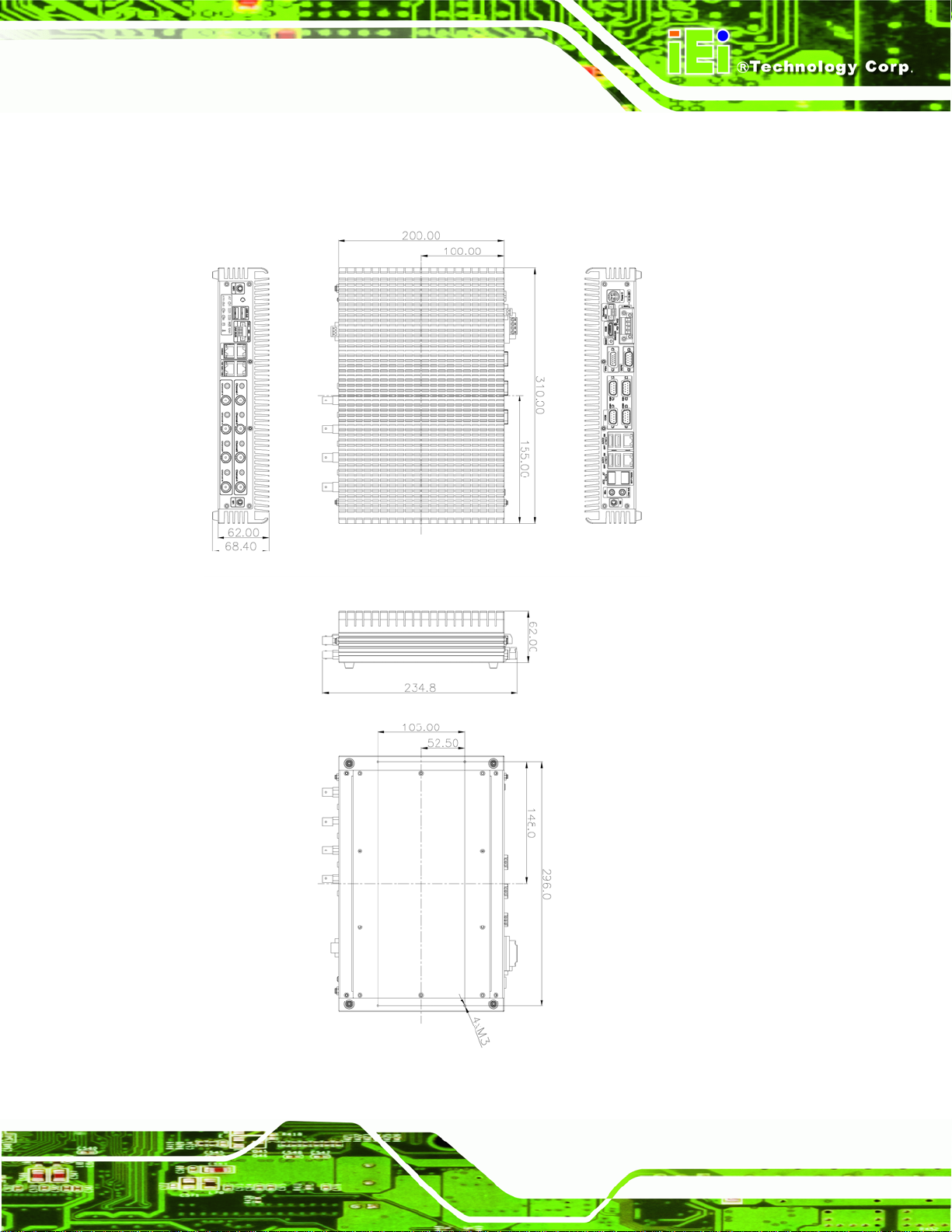
310 mm x 200 mm x 62 mm (W x D x H)
1.5 Connector Panel
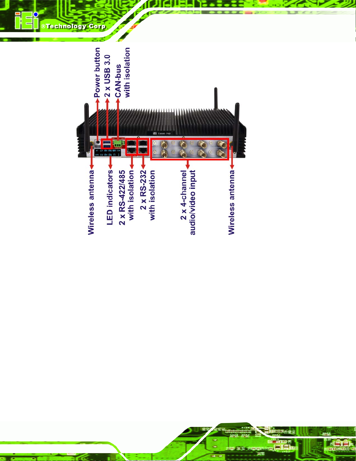
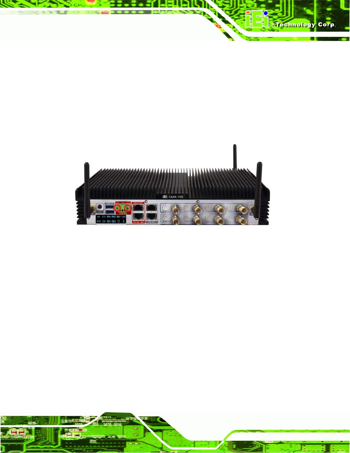
1.5.1 Front Panel
The TANK-700 front panel contains:
2 x 4-channel audio/video input (on selected models)
1 x CAN-bus terminal block with isolation
12 x LED indicators
1 x Power button
2 x RS-232 serial ports with isolation
2 x RS-422/485 serial ports with isolation
2 x USB 3.0 port connectors
2 x Wireless antenna connectors
An overview of the front panel is shown in
Figure 1-26.
Page 5
Page 17
TANK-700 Embedded System
Figure 1-2: TANK-700 Front Panel
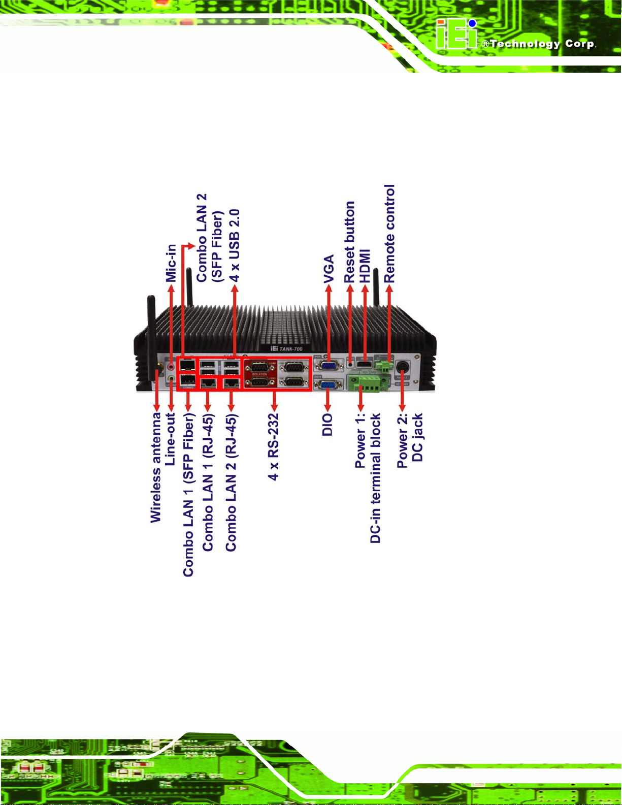
1.5.2 Rear Panel
The TANK-700 rear panel contains:
1 x DIO port
1 x 2-pin terminal block for remote control
2 x RJ-45 Gigabit LAN ports
1 x HDMI port
1 x Line-out port (green)
1 x Mic-in port (pink)
1 x 4-pin power jack for 10.5V (+/-0.3V) ~ 36V power input
1 x Power terminal block for 9V (+/-0.3V) ~ 36V power input
1 x Reset button
4 x RS-232 serial ports
2 x SFP Fiber Gigabit LAN ports
Page 6
Page 18
TANK-700 Embedded System
4 x USB 2.0 port connectors
1 x VGA output
1 x Wireless antenna connector
An overview of the rear panel is shown in
6Figure 1-3 below.
Figure 1-3: TANK-700 Rear Panel
Page 7
Page 19
TANK-700 Embedded System
NOTE:
The TANK-700 provides two pairs of combo LANs. For each pair of
combo LAN, only one LAN port can work at one time, and the SFP
Fiber port works prior to the RJ-45 one. When a LAN port is working,
the corresponding LED indicator lights up. Refer to Section
locations of the LED indicators.
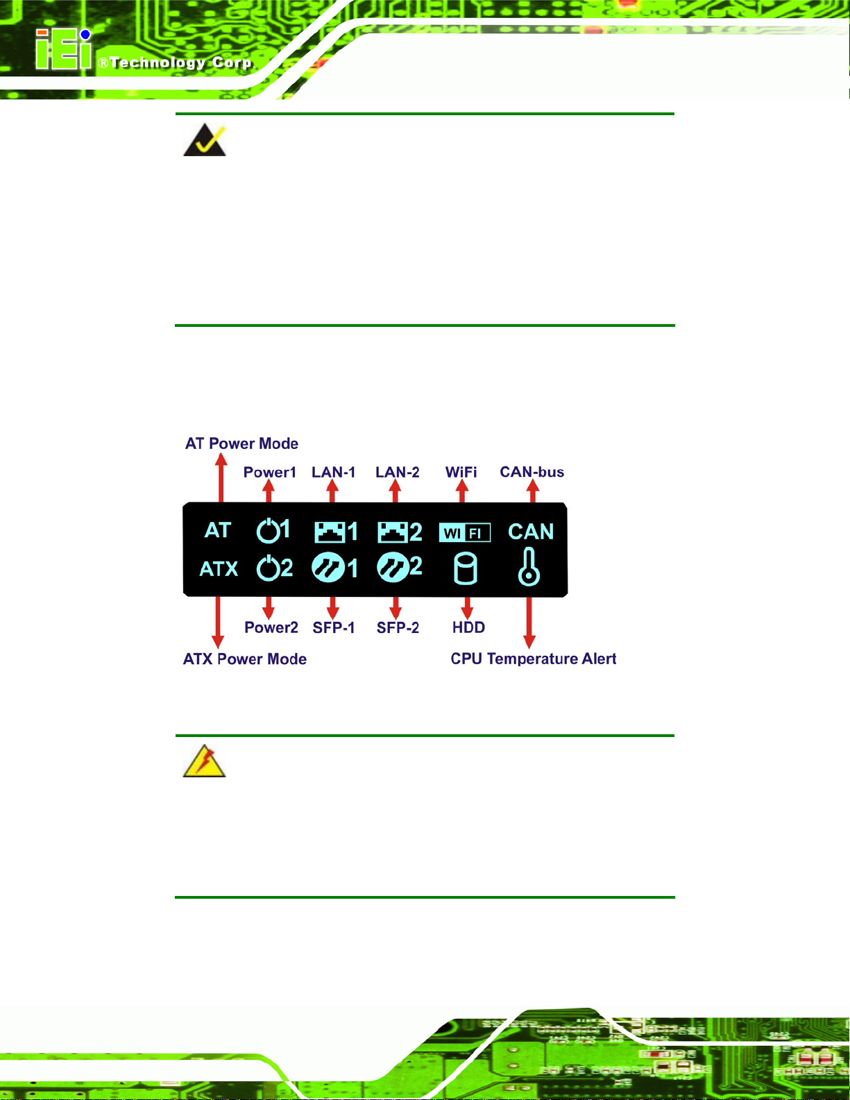
1.6 LED Indicators
There are several indicators on the front panel of the TANK-700 as shown in Figure 1-4.
1.6 for the
Page 8
Figure 1-4: TANK-700 LED Indicators
WARNING:
The CPU Temperature Alert LED turns red when the CPU temperature
is too high. If this situation occurs, lower the environment temperature
or close some running applications to cool down the CPU.
Page 20
TANK-700 Embedded System
1.7 Dimensions
The physical dimensions are shown below:
Figure 1-5: Physical Dimensions (millimeters)
Page 9
Page 21

TANK-700 Embedded System
Chapter
2
2 Unpacking
Page 10
Page 22

TANK-700 Embedded System
2.1 Anti-static Precautions
WARNING:
Failure to take ESD precautions during installation may result in
permanent damage to the TANK-700 and severe injury to the user.
Electrostatic discharge (ESD) can cause serious damage to electronic components,
including the TANK-700. Dry climates are especially susceptible to ESD. It is therefore
critical that whenever the TANK-700 or any other electrical component is handled, the
following anti-static precautions are strictly adhered to.
Wear an anti-static wristband: Wearing a simple anti-static wristband can
help to prevent ESD from damaging the board.
Self-grounding: Before handling the board touch any grounded conducting
material. During the time the board is handled, frequently touch any
conducting materials that are connected to the ground.
Use an anti-static pad: When configuring the TANK-700, place it on an
antic-static pad. This reduces the possibility of ESD damaging the TANK-700.
2.2 Unpacking Precautions
When the TANK-700 is unpacked, please do the following:
Follow the anti-static precautions outlined in Section
Make sure the packing box is facing upwards so the TANK-700 does not fall
out of the box.
Make sure all the components shown in Section
2.1.
2.3 are present.
Page 11
Page 23
2.3 Unpacking Checklist
NOTE:
If some of the components listed in the checklist below are missing,
please do not proceed with the installation. Contact the IEI reseller or
vendor you purchased the TANK-700 from or contact an IEI sales
representative directly. To contact an IEI sales representative, please
TANK-700 Embedded System
send an email to
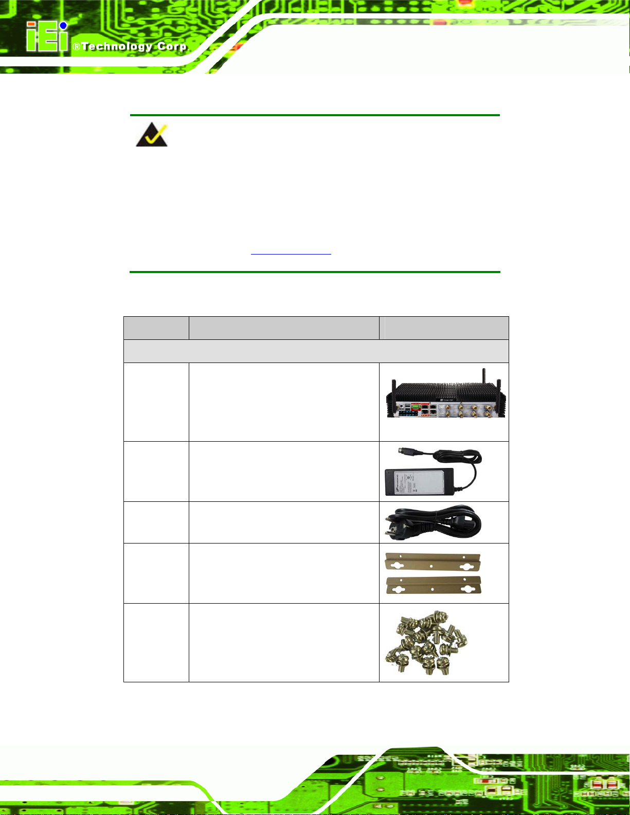
The TANK-700 is shipped with the following components:
Quantity Item and Part Number Image
Standard
1 TANK-700 Series
1 Power adapter
(P/N: 63040-010090-020-RS)
1 Power cord
(P/N: 32702-000401-100-RS)
sales@iei.com.tw.
Page 12
2 Mounting bracket
(P/N: 41020-0163J4-00-RS)
8 Mounting bracket screw
(P/N: 44033-030062-RS)
Page 24
TANK-700 Embedded System
Quantity Item and Part Number Image
Standard
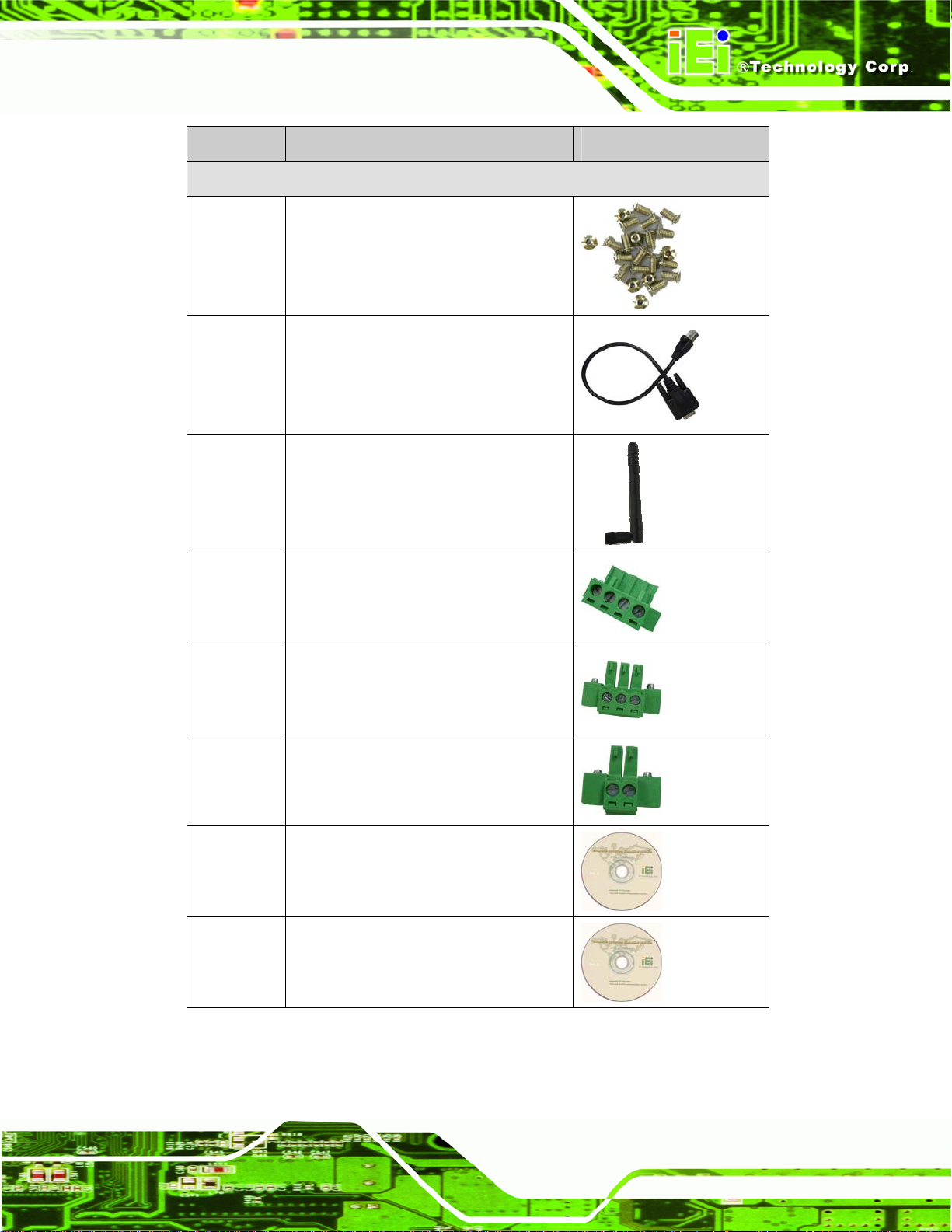
8 Chassis screw
(P/N: 44013-030041-RS)
4 RJ-45 to DB-9 COM port cable
(P/N: 32005-000200-200-RS)
3 Wireless antenna
(P/N: 32505-000900-100-RS)
1 Pluggable DC-in terminal block
(P/N: 33502-000055-RS)
1 Pluggable CAN-bus terminal block
(P/N: 33502-000007-RS)
1 Pluggable remote control terminal
block (P/N: 33101-000422-RS)
1 One Key Recovery CD
(P/N: IEI-7B000-000478-RS)
1 User manual and driver CD
Page 13
Page 25
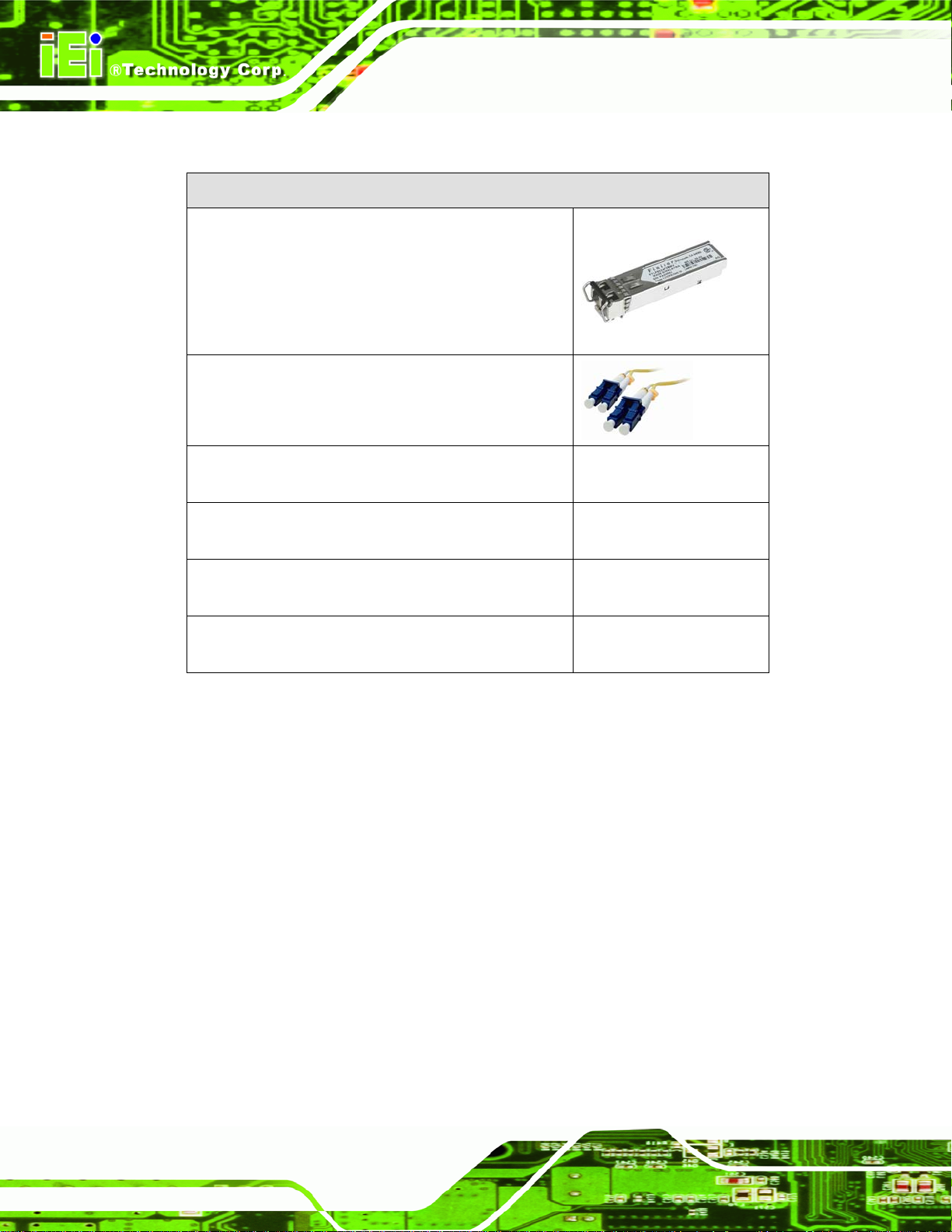
The following table lists the optional items that can be purchased separately.
Optional
Gigabit Ethernet SFP module
(P/N: SFP1G-SX/-I
SFP1G-MLX/-I
TANK-700 Embedded System
SFP1G-LX10/-I
SFP1G-ZX70/-I)
Fiber cord
(P/N: FPC-LCLC-MM3M
FPC-LCLC-SS3M)
OS: Win CE 6.0 (CD-ROM)
(P/N: TANK-700-QM67-CE060-R10)
OS: Win XPE (CD-ROM)
(P/N: TANK-700-QM67-XPE-R10)
OS: Linux (CD-ROM)
(P/N: TANK-700-QM67-LNX-R10)
OS: Win 7 Embedded (CD-ROM)
(P/N: TANK-700-QM67-WES7E-R10)
Page 14
Page 26

TANK-700 Embedded System
Chapter
3
3 Installation
Page 15
Page 27

3.1 Installation Precautions
During installation, be aware of the precautions below:
Read the user manual: The user manual provides a complete description of
the TANK-700, installation instructions and configuration options.
DANGER! Disconnect Power: Power to the TANK-700 must be
disconnected during the installation process, or before any attempt is made to
access the rear panel. Electric shock and personal injury might occur if the
rear panel of the TANK-700 is opened while the power cord is still connected
to an electrical outlet.
Qualified Personnel: The TANK-700 must be installed and operated only by
trained and qualified personnel. Maintenance, upgrades, or repairs may only
be carried out by qualified personnel who are familiar with the associated
dangers.
TANK-700 Embedded System
Air Circulation: Make sure there is sufficient air circulation when installing the
TANK-700. The TANK-700’s cooling vents must not be obstructed by any
objects. Blocking the vents can cause overheating of the TANK-700. Leave at
least 5 cm of clearance around the TANK-700 to prevent overheating.
Grounding: The TANK-700 should be properly grounded. The voltage feeds
must not be overloaded. Adjust the cabling and provide external overcharge
protection per the electrical values indicated on the label attached to the back
of the TANK-700.
3.2 Hard Disk Drive (HDD) Installation
To install the hard drive, please follow the steps below:
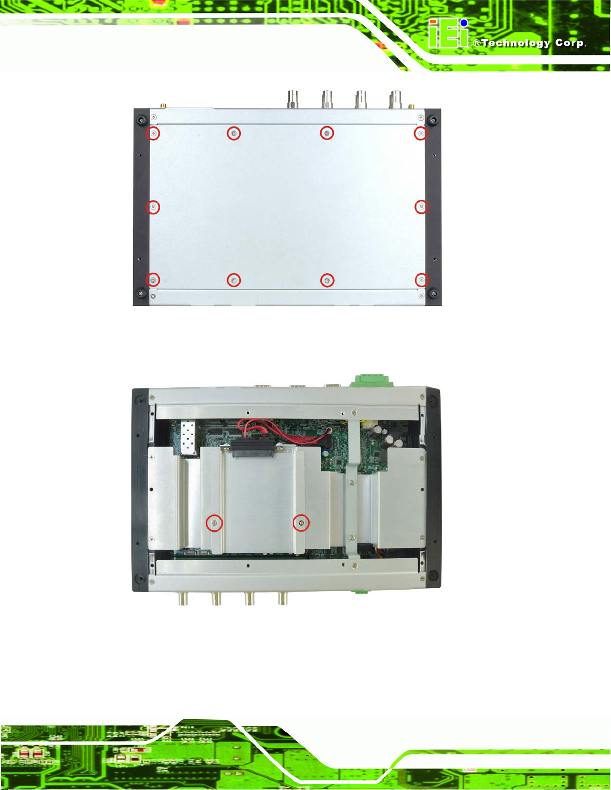
Step 1: Remove the bottom panel by removing the 10 retention screws from the bottom
panel (
Figure 3-1).
Page 16
Page 28
TANK-700 Embedded System
Figure 3-1: Bottom Panel Retention Screws
Step 2: Remove the 2 HDD bracket retention screws (Figure 3-2).
Figure 3-2: HDD Bracket Retention Screws
Step 3: Lift the HDD bracket out of the TANK-700 and put it on a flat surface.
Step 4: Attach the HDD to the HDD bracket. Secure the HDD with the HDD bracket by
four retention screws (
Figure 3-3).
Page 17
Page 29
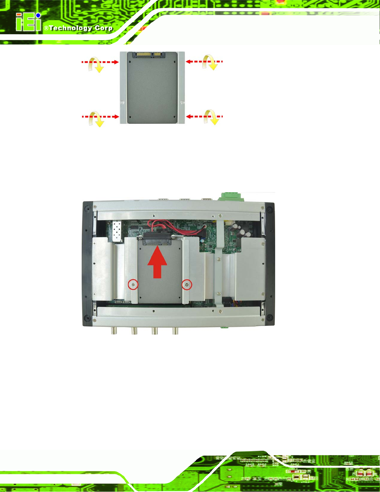
Figure 3-3: HDD Installation
Step 5: Slide the HDD bracket to connect the HDD to the SATA connector. Secure the
HDD bracket with TANK-700 by the 2 retention screws that were previously
TANK-700 Embedded System
removed (
Figure 3-4: HDD Bracket Installation
Figure 3-4).
Step 6: Reinstall the bottom panel to the TANK-700.
3.3 Pluggable CAN-bus Terminal Block Installation
To install the pluggable CAN-bus terminal block, please follow the steps below:
Step 1: Locate the CAN-bus terminal block connector. The location of the connector is
Figure 1-2.
Page 18
shown in
Page 30
TANK-700 Embedded System
Step 2: Align the pluggable CAN-bus terminal block with the CAN-bus terminal block
connector on the TANK-700.
Step 3: Once aligned, insert the pluggable CAN-bus terminal block into the CAN-bus
terminal block connector.
Step 4: Secure the pluggable CAN-bus terminal block to the external interface by
tightening the two retention screws on either side of the terminal block
Figure 3-5).
(
Figure 3-5: Pluggable CAN-bus Terminal Block Installation
3.4 Pluggable DC-In Terminal Block Installation
To install the pluggable DC-in terminal block, please follow the steps below:
Step 1: Locate the DC-in terminal block connector. The location of the connector is
shown in
Step 2: Align the pluggable DC-in terminal block with the DC-in terminal block connector
on the TANK-700.
Step 3: Once aligned, insert the pluggable DC-in terminal block into the DC-in terminal
block connector.
Step 4: Secure the pluggable DC-in terminal block to the external interface by tightening
the two retention screws on either side of the terminal block (
Figure 1-3.
Figure 3-6).
Page 19
Page 31

Figure 3-6: Pluggable DC-in Terminal Block Installation
TANK-700 Embedded System
3.5 Pluggable Remote Control Terminal Block Installation
To install the pluggable remote control terminal block, please follow the steps below:
Step 1: Locate the remote control terminal block connector. The location of the
connector is shown in
Step 2: Align the pluggable remote control terminal block with the remote control
terminal block connector on the TANK-700.
Step 3: Once aligned, insert the pluggable remote control terminal block into the remote
control terminal block connector.
Step 4: Secure the pluggable remote control terminal block to the external interface by
tightening the two retention screws on either side of the terminal block
Figure 3-7).
(
Figure 1-3.
Page 20
Page 32

TANK-700 Embedded System
Figure 3-7: Pluggable Remote Control Terminal Block Installation
3.6 SFP Module Installation
To install an SFP module, please follow the steps below:
Step 1: Locate the SFP fiber connectors. The locations of the connectors are shown in
Figure 1-3.
Step 2: Align the SFP module with one of the SFP fiber connectors on the TANK-700
Figure 3-8).
(
Step 3: Once aligned, slide the SFP module into place (
Figure 3-8).
Figure 3-8: SFP Module Installation
Page 21
Page 33

3.7 SO-DIMM Installation
WARNING:
Using incorrectly specified SO-DIMM may cause permanently damage
the TANK-700. Please make sure the purchased SO-DIMM complies
with the memory specifications of the TANK-700.
To install a SO-DIMM into a SO-DIMM socket, please follow the steps below.
Step 1: Remove the bottom panel by removing the 10 retention screws from the bottom
TANK-700 Embedded System
panel (
Step 2: Remove the 8 retention screws (
cables connected to the TANK-700, and then lift the bracket out of the
TANK-700.
Figure 3-1).
Figure 3-9), unplug the SATA signal and power
Page 22
Figure 3-9: Retention Screws
Step 3: Locate the SO-DIMM socket on the motherboard (
Figure 3-10).
Page 34

TANK-700 Embedded System
Figure 3-10: SO-DIMM Socket
Step 4: Align the SO-DIMM with the socket. The SO-DIMM must be oriented in such a
way that the notch in the middle of the SO-DIMM must be aligned with the
plastic bridge in the socket (
Step 5: Push the SO-DIMM into the socket at an angle (
Figure 3-118).
84Figure 3-11).
Figure 3-11: SO-DIMM Installation
Step 6: Gently pull the arms of the SO-DIMM socket out and push the rear of the
SO-DIMM down (
84Figure 3-11).
Step 7: Release the arms on the SO-DIMM socket. They clip into place and secure the
SO-DIMM in the socket.
Page 23
Page 35

Step 8: Install the bracket that was previously removed in the same position it was
before.
Step 9: Reinstall the bottom panel to the TANK-700.
TANK-700 Embedded System
3.8 Mounting the System with Mounting Brackets
To mount the embedded system onto a wall or some other surface using the two mounting
brackets, please follow the steps below.
Step 1: Turn the embedded system over.
Step 2: Align the two retention screw holes in each bracket with the corresponding
retention screw holes on the sides of the bottom surface (
Figure 3-12).
Figure 3-12: Mounting Bracket Retention Screws
Step 3: Secure the brackets to the system by inserting two retention screws into each
bracket (
Step 4: Drill holes in the intended installation surface.
Figure 3-12).
Page 24
Step 5: Align the mounting holes in the sides of the mounting brackets with the predrilled
holes in the mounting surface.
Step 6: Insert four retention screws, two in each bracket, to secure the system to the
wall.
Page 36

TANK-700 Embedded System
3.9 External Peripheral Interface Connectors
The TANK-700 has the following connectors. Detailed descriptions of the connectors can
be found in the subsections below.
Audio
Audio/video input connectors
CAN-bus
DIO
Ethernet
GPIO for remote control
HDMI
Power button
Power input
Reset button
RS-232
RS-422/485
USB
VGA
Wireless antenna
Page 25
Page 37

3.9.1 ACC Mode Selection
The TANK-700 allows turning the ACC mode on or off. The setting can be made through
the ACC mode switch on the rear panel as shown below.
TANK-700 Embedded System
Figure 3-13: ACC Mode Switch
3.9.2 AT/ATX Power Mode Selection
The TANK-700 supports AT and ATX power modes. The setting can be made through the
AT/ATX power mode switch on the rear panel as shown below.
Page 26
Figure 3-14: AT/ATX Power Mode Switch
Page 38

TANK-700 Embedded System
3.9.3 Audio Connector
CN Label:
CN Type:
CN Location:
The audio jacks connect to external audio devices.
Microphone (Pink): Connects a microphone.
Line Out port (Green): Connects to a headphone or a speaker. With
multi-channel configurations, this port can also connect to front speakers.
Figure 3-15: Audio Connector
Line out and Mic
Audio jack
See Figure 3-15
3.9.4 Audio/Video Input Connectors
The TANK-700 can support up to eight video inputs and eight audio inputs through the
BNC and RCA connectors on the front panel. The locations of the connectors are shown
in
Figure 1-2.
3.9.5 CAN-bus Terminal Block
There is one 3-pin CAN-bus terminal block. The pinouts are shown in Figure 3-16
Figure 3-16: CAN-bus Terminal Block Pinouts
Page 27
Page 39

3.9.6 Digital Input/Output Connector
CN Label: DIO x 8
TANK-700 Embedded System
CN Type:
CN Location:
CN Pinouts:
DB-9 male connector
Figure 1-3
See
Table 3-1 and Figure 3-17
See
The digital I/O connector provides programmable input and output for external devices.
The pinouts for the digital I/O connector are listed in the table below.
Pin Description Pin Description
1 DIN0 6 DOUT2
2 DOUT0 7 DIN3
3 DIN1 8 DOUT3
4 DOUT1 9 VCC5
5 DIN2
Table 3-1: DIO Connector Pinouts
Figure 3-17: DIO Connector Pinout Location
3.9.7 HDMI Connector
CN Label: HDMI
CN Type:
CN Location:
CN Pinouts:
The HDMI (High-Definition Multimedia Interface) connector connects to digital audio or
video sources.
Page 28
HDMI type A connector
4Figure 1-3
See
4Table 3-2
See
Page 40

TANK-700 Embedded System
Pin Description Pin Description
1 HDMI_DATA2 2 GND
3 HDMI_DATA2# 4 HDMI_DATA1
5 GND 6 HDMI_DATA1#
7 HDMI_DATA0 8 GND
9 HDMI_DATA0# 10 HDMI_CLK
11 GND 12 HDMI_CLK#
13 N/C 14 N/C
15 HDMI_SCL 16 HDMI_SDA
17 GND 18 +5V
19 HDMI_HPD 20 HDMI_GND
21 HDMI_GND 22 HDMI_GND
23 HDMI_GND
Table 3-2: HDMI Connector Pinouts
3.9.8 LAN Connectors
CN Label: LAN
CN Type:
CN Location:
CN Pinouts:
The LAN connectors allow connection to an external network.
Step 1: Locate the RJ-45 connectors. The locations of the RJ-45 connectors are
shown in
Step 2: Align the connectors. Align the RJ-45 connector on the LAN cable with one of
the RJ-45 connectors on the TANK-700. See
RJ-45
Figure 1-3
See
Table 3-3
See
Figure 1-3.
Figure 3-18.
Page 29
Page 41

TANK-700 Embedded System
Figure 3-18: LAN Connection
Step 3: Insert the LAN cable RJ-45 connector. Once aligned, gently insert the LAN
cable RJ-45 connector into the on-board RJ-45 connector.
Pin Description Pin Description
1 TRD1P0 5 TRD1P2
2 TRD1N0 6 TRD1N2
3. TRD1P1 7 TRD1P3
4. TRD1N1 8 TRD1N3
Table 3-3: LAN Pinouts
Figure 3-19: RJ-45 Ethernet Connector
Page 30
The RJ-45 Ethernet connector has two status LEDs, one green and one yellow. The green
LED indicates activity on the port and the yellow LED indicates the port is linked. See
Table 3-4.
Page 42

TANK-700 Embedded System
Activity/Link LED Speed LED
STATUS
Off No link Off 10 Mbps connection
Yellow Linked Green 100 Mbps connection
Blinking TX/RX activity Orange 1 Gbps connection
Table 3-4: RJ-45 Ethernet Connector LEDs
DESCRIPTION STATUS DESCRIPTION
3.9.9 Power Input, 4-pin Terminal Block
CN Label: POWER 1
CN Type:
CN Location:
CN Pinouts:
Connect the leads of a 9V~36V DC power supply into the terminal block. Make sure that
the power and ground wires are attached to the correct sockets of the connector.
Pin Description Pin Description
4-pin terminal block
Figure 1-3
See
Table 3-5 and Figure 3-20
See
1 GND 3 Power button
2 VCC 4 ACC
Table 3-5: 4-pin Terminal Block Pinouts
Figure 3-20: 4-pin Terminal Block Pinout Location
3.9.10 Power Input, 4-pin DIN Connector
CN Label: POWER 2
CN Type:
CN Location:
CN Pinouts:
4-pin DIN connector
Figure 1-3
See
Table 3-6 and Figure 3-21
See
Page 31
Page 43

The power connector connects to the 10.5V~36V DC power adapter.
TANK-700 Embedded System
Figure 3-21: Power Input Connector
Pin Description Pin Description
1 +12V 3 +12V
2 GND 4 GND
Table 3-6: Power Input Pinouts
3.9.11 Remote Control Connector
CN Label: Remoter
CN Type:
CN Location:
CN Pinouts:
The 2-pin terminal block connects to a remote control device. Users can control the
system power on/off by inputting high or low voltage into the terminal block.
2-pin terminal block
Figure 1-3
See
Figure 3-22
See
Page 32
Turn off the system: 2 V ~ 5 V input
Turn on the system: less than 0.4 V input
Figure 3-22: Remote Control Terminal Block Pinout Location
Page 44

TANK-700 Embedded System
3.9.12 RJ-45 RS-232 Serial Ports
CN Label: RS 232
CN Type:
CN Location:
CN Pinouts:
RS-232 serial port devices can be attached to the RJ-45 RS-232 serial ports on the front
panel.
Step 1: Locate the RJ-45 RS-232 connectors. The locations of the RJ-45 RS-232
connectors are shown in
Step 2: Insert the RJ-45 connector. Insert the RJ-45 connector on the RJ-45 to DB-9
COM port cable to one of the RJ-45 RS-232 connectors on the TANK-700. See
Figure 3-23.
RJ-45
Figure 1-2
See
Table 3-7 and Figure 3-24
See
Figure 1-2.
Figure 3-23: RJ-45 RS-232 Serial Device Connection
Step 3: Insert the serial connector. Insert the DB-9 connector of a serial device into
the DB-9 connector on the RJ-45 to DB-9 COM port cable.
Step 4: Secure the connector. Secure the serial device connector to the external
interface by tightening the two retention screws on either side of the connector.
Page 33
Page 45

TANK-700 Embedded System
Figure 3-24: RJ-45 RS-232 Serial Port Pinout Location
Pin Description Pin Description
1 RI 5 RTS
2 DTR 6 RX
3. CTS 7 DSR
4. TX 8 DCD
Table 3-7: RJ-45 RS-232 Serial Port Pinouts
Figure 3-25: DB-9 Connector Pinout Location
Pin Description Pin Description
1 DCD 6 DSR
2 RX 7 RTS
3 TX 8 CTS
4 DTR 9 RI
5 GND
Table 3-8: DB-9 Connector Pinouts
Page 34
Page 46

TANK-700 Embedded System
3.9.13 RJ-45 RS-422/485 Serial Ports
CN Label: RS 422/485
CN Type:
CN Location:
CN Pinouts:
RS-422/485 serial port devices can be attached to the RJ-45 RS-422/485 serial ports on
the front panel.
Step 1: Locate the RJ-45 RS-422/485 connectors. The locations of the RJ-45
RS-422/485 connectors are shown in
Step 2: Insert the RJ-45 connector. Insert the RJ-45 connector on the RJ-45 to DB-9
COM port cable to one of the RJ-45 RS-422/485 connectors on the TANK-700.
See
RJ-45
Figure 1-2
See
Table 3-9 and Figure 3-27
See
Figure 3-26.
Figure 1-2.
Figure 3-26: RJ-45 RS-422/485 Serial Device Connection
Step 3: Insert the serial connector. Insert the DB-9 connector of a serial device into
the DB-9 connector on the RJ-45 to DB-9 COM port cable.
Step 4: Secure the connector. Secure the serial device connector to the external
interface by tightening the two retention screws on either side of the connector.
Page 35
Page 47

TANK-700 Embedded System
Figure 3-27: RJ-45 RS-422/485 Serial Port Pinout Location
Pin Description Pin Description
1 N/A 5 N/A
2 TXD485# 6 RXD485#
3. N/A 7 N/A
4. TXD485+ 8 RXD485+
Table 3-9: RJ-45 RS-422/485 Serial Port Pinouts
Figure 3-28: DB-9 Connector Pinout Location
Pin Description (RS-422) Description (RS-485)
1 RXD422+ N/A
2 RXD422# N/A
3 TXD422+ TXD485+
4 TXD422# TXD485#
5 GND GND
6 N/A N/A
7 N/A N/A
Page 36
8 N/A N/A
9 N/A N/A
Table 3-10: DB-9 Connector Pinouts
Page 48

TANK-700 Embedded System
3.9.14 RS-232 Serial Port Connectors
CN Label:
CN Type:
CN Location:
CN Pinouts:
RS-232 serial port devices can be attached to the DB-9 ports on the rear panel.
Step 1: Locate the DB-9 connector. The locations of the DB-9 connectors are shown
Figure 1-3.
in
Step 2: Insert the serial connector. Insert the DB-9 connector of a serial device into
the DB-9 connector on the external peripheral interface. See
COM1, COM2, COM3 and COM4
DB-9 connectors
Figure 1-3
See
Table 3-11 and Figure 3-30
See
Figure 3-29.
Figure 3-29: Serial Device Connector
Step 3: Secure the connector. Secure the serial device connector to the external
interface by tightening the two retention screws on either side of the connector.
Page 37
Page 49

Pin Description Pin Description
1 DCD 6 DSR
2 RX 7 RTS
3 TX 8 CTS
4 DTR 9 RI
5 GND
TANK-700 Embedded System
Table 3-11: Serial Port Pinouts
Figure 3-30: Serial Port Pinout Location
3.9.15 SFP Fiber Connectors
The TANK-700 has two SFP fiber connectors. The locations of the connectors are shown
in
Figure 1-3. To install an SFP module, refer to Section 3.6.
3.9.16 USB Connectors
CN Label: USB
Page 38
CN Type:
CN Location:
CN Pinouts:
The USB ports are for connecting USB peripheral devices to the system.
Step 1: Locate the USB connectors. The locations of the USB connectors are shown
Figure 1-3.
in
Step 2: Align the connectors. Align the USB device connector with one of the
connectors. See
USB port
Figure 1-2 and Figure 1-3
See
Table 3-12
See
Figure 3-31.
Page 50

TANK-700 Embedded System
Figure 3-31: USB Device Connection
Step 3: Insert the device connector. Once aligned, gently insert the USB device
connector into the on-board connector.
Pin Description Pin Description
1 VCC 5 VCC
2 DATA- 6 DATA3 DATA+ 7 DATA+
4 GROUND 8 GROUND
Table 3-12: USB Port Pinouts
3.9.17 VGA Connector
CN Label: VGA
CN Type:
15-pin Female
Figure 1-3
CN Location:
CN Pinouts:
See
Figure 3-33 and Table 3-13
See
The VGA connector connects to a monitor that accepts VGA video input.
Page 39
Page 51

Step 1: Locate the female DB-15 connector. The location of the female DB-15
TANK-700 Embedded System
connector is shown in
Step 2: Align the VGA connector. Align the male DB-15 connector on the VGA screen
cable with the female DB-15 connector on the external peripheral interface.
Step 3: Insert the VGA connector. Once the connectors are properly aligned with,
insert the male connector from the VGA screen cable into the female connector
on the TANK-700. See
Figure 1-3.
Figure 3-32.
Page 40
Figure 3-32: VGA Connector
Step 4: Secure the connector. Secure the DB-15 VGA connector from the VGA
monitor to the external interface by tightening the two retention screws on either
side of the connector.
Figure 3-33: VGA Connector
Page 52

TANK-700 Embedded System
Pin Description Pin Description
1 RED 2 GREEN
3 BLUE 4 NC
5 GND 6 GND
7 GND 8 GND
9 VCC / NC 10 GND
11 NC 12 DDC DAT
13 HSYNC 14 VSYNC
15 DDCCLK
Table 3-13: VGA Connector Pinouts
3.10 Powering On/Off the System
WARNING:
Make sure a power supply with the correct input voltage is being fed into
the system. Incorrect voltages applied to the system may cause damage to
the internal electronic components and may also cause injury to the user.
Power on the system: press the power button for 3 seconds
Power off the system: press the power button for 6 seconds
Figure 3-34: Power Button
Page 41
Page 53

3.11 Redundant Power
The TANK-700 is a system that supports redundant power. The redundant power input
increases the reliability of the system and prevents data loss and system corruption from
sudden power failure. The system can instantly and uninterruptedly switch to the second
power input when the main power is unavailable or in low voltage capacity.
There are two power connectors on the rear panel. Power 1 connector is a 4-pin terminal
block that supports ACC On signal. Power 2 connector is a DIN connector that can directly
connect to a power adapter. The supported power input voltages are:
Power 1: 9 V (+/-0.3 V) ~ 36 V
Power 2: 10.5 V (+/-0.3 V) ~ 36 V
TANK-700 Embedded System
Page 42
Figure 3-35: Power Connectors
When the system is in ACC On mode, the main power input is from Power 1 connector;
when the system is in ACC Off mode, the main power input is from Power 2 connector.
The ACC on/off mode is selected by the ACC mode switch on the rear panel (
3-13).
The following sections describe how the redundant power works in ACC On mode and
ACC Off mode.
Figure
Page 54

TANK-700 Embedded System
3.11.1 ACC ON
NOTE:
In ACC On mode, the Power 1 connector must connect to the ACC on
signal to be able to control system power.
The ACC On mode is designed for vehicle applications. When the TANK-700 is in ACC
On mode, the main power input is the Power 1 connector and the backup power is from
the Power 2 connector.
3.11.1.1 Boot-up
When both power connectors are connected to a power source with over 9 V, the two
power LEDs on the front panel remain off until the ACC ON signal jumps from low to
high. The user can choose AT power mode or ATX power mode to control the system.
The following flow diagrams show the boot-up process and the LED status in AT and ATX
power modes.
Figure 3-36: ACC On: AT Mode
Figure 3-37: ACC On: ATX Mode
Page 43
Page 55

3.11.1.2 Switch to Backup Power
During operation, system power will switch from Power 1 to Power 2 automatically when
the following situations occur:
Power 1 < 9V and Power 2 > 10.5V
Power 1 > 9V, but the ACC ON signal jumps from high to low
Power 1 is unplugged and Power 2 > 10.5V
The following flow diagram shows how the power is switched between Power 1 and
Power 2 and their LED statuses.
TANK-700 Embedded System
Figure 3-38: ACC On: Switch Between PWR1 and PWR2
3.11.1.3 Shutdown
The system will shutdown in the following situations:
Power 1 < 9V and Power 2 < 10.5V
Power 1 > 9V, Power 2 < 10.5V and ACC ON signal jumps from high to low
Press Power button for 6 seconds
The following flow diagram shows the system shutdown process and the LED statuses.
Page 44
Figure 3-39: ACC On: Shutdown
Page 56

TANK-700 Embedded System
NOTE:
To turn on the system in ATX power mode, press the Power button for
three seconds. Press the Power button for six seconds to turn off the
system.
3.11.2 ACC OFF
When the TANK-700 is in ACC Off mode, the main power input is the Power 2 connector
and the backup power is from the Power 1 connector.
3.11.2.1 Boot-up
When both power connectors are connected to a power source with over 9 V, the two
power LEDs on the front panel turn on. The user can choose AT power mode or ATX
power mode to control the system. The following flow diagrams show the boot-up process
and the LED status in AT and ATX power modes.
Figure 3-40: ACC Off: AT Mode
Figure 3-41: ACC Off: ATX Mode
Page 45
Page 57

3.11.2.2 Switch to Backup Power
During operation, system power switches from Power 2 to Power 1 automatically when the
following situations occur:
Power 2 < 10.5V and Power 1 > 9V
Power 2 is unplugged and Power 1 > 9V
The following flow diagram shows how the power is switched between Power 2 and
Power 1 and their LED statuses.
TANK-700 Embedded System
Figure 3-42: ACC Off: Switch Between PWR1 and PWR2
NOTE:
System power can switch between Power 2 and Power 1 automatically
when a 12 V power adapter is being connected to Power 2 and the
power input of Power 1 is from 9 V to 16 V. If Power 2 is unplugged and
the power input of Power 1 is over 16 V, system power will switch to
Power 1 automatically. However, the system remains using the power
source from Power 1 even if Power 2 is re-plugged.
System power can switch between Power 2 and Power 1 automatically
when a 19 V power adapter is being connected to Power 2 and the
power input of Power 1 is from 9 V to 26 V. If Power 2 is unplugged and
the power input of Power 1 is over 26 V, system power will switch to
Power 1 automatically. However, the system remains using the power
Page 46
source from Power 1 even if Power 2 is re-plugged.
Page 58

TANK-700 Embedded System
3.11.2.3 Shutdown
The system will shutdown in the following situations:
Power 2 < 10.5V and Power 1 < 9V
Press Power buttons for 6 seconds
The following flow diagram shows the system shutdown process and the LED statuses.
Figure 3-43: ACC Off: Shutdown
NOTE:
The power LED turns off when the power cable is unplugged from the
system.
Page 47
Page 59

TANK-700 Embedded System
Chapter
4
4 BIOS
Page 48
Page 60

TANK-700 Embedded System
4.1 Introduction
The BIOS is programmed onto the BIOS chip. The BIOS setup program allows changes to
certain system settings. This chapter outlines the options that can be changed.
4.1.1 Starting Setup
The UEFI BIOS is activated when the computer is turned on. The setup program can be
activated in one of two ways.
1. Press the DEL or F2 key as soon as the system is turned on or
2. Press the DEL or F2 key when the “Press DEL or F2 to enter SETUP”
message appears on the screen.
If the message disappears before the DEL or F2 key is pressed, restart the computer and
try again.
4.1.2 Using Setup
Use the arrow keys to highlight items, press ENTER to select, use the PageUp and
PageDown keys to change entries, press F1 for help and press E
keys are shown in.
Key Function
Up arrow Move to previous item
Down arrow Move to next item
Left arrow Move to the item on the left hand side
Right arrow Move to the item on the right hand side
+ Increase the numeric value or make changes
- Decrease the numeric value or make changes
Page Up key Increase the numeric value or make changes
Page Dn key Decrease the numeric value or make changes
SC to quit. Navigation
Page 49
Page 61

Key Function
Esc key Main Menu – Quit and not save changes into CMOS
F1 General help, only for Status Page Setup Menu and Option
F2 Previous values
F3 Load optimized defaults
F4 Save changes and Exit BIOS
Table 4-1: BIOS Navigation Keys
4.1.3 Getting Help
TANK-700 Embedded System
Status Page Setup Menu and Option Page Setup Menu --
Exit current page and return to Main Menu
Page Setup Menu
When F1 is pressed a small help window describing the appropriate keys to use and the
possible selections for the highlighted item appears. To exit the Help Window press E
the F1 key again.
4.1.4 Unable to Reboot After Configuration Changes
If the computer cannot boot after changes to the system configuration is made, CMOS
defaults. Use the jumper described in Chapter 2.
4.1.5 BIOS Menu Bar
The menu bar on top of the BIOS screen has the following main items:
Main – Changes the basic system configuration.
Advanced – Changes the advanced system settings.
Chipset – Changes the chipset settings.
Boot – Changes the system boot configuration.
Security – Sets User and Supervisor Passwords.
SC or
Page 50
Save & Exit – Selects exit options and loads default settings.
The following sections completely describe the configuration options found in the menu
items at the top of the BIOS screen and listed above.
Page 62

TANK-700 Embedded System
4.2 Main
The Main BIOS menu (BIOS Menu 1) appears when the BIOS Setup program is entered.
The Main menu gives an overview of the basic system information.
Aptio Setup Utility – Copyright (C) 2010 American Megatrends, Inc.
Main Advanced Chipset Boot Security Save & Exit
BIOS Information
BIOS Vendor American Megatrends
Core Version 4.6.4.0 0.15
Compliency UEFI 2.1
Project Version SA41AR13.ROM
Build Date and Time 08/09/2011 11:53:40
iWDD Vendor ICP
iWDD Version SA41ET12.bin
System Date [Thu 08/11/2011]
System Time [15:10:27]
Access Level Administrator
Version 2.10.1208. Copyright (C) 2010 American Megatrends, Inc.
Set the Date. Use Tab to
switch between Data
elements.
----------------------
ÅÆ
: Select Screen
↑ ↓: Select Item
Enter Select
+ - Change Opt.
F1 General Help
F2 Previous Values
F3 Optimized Defaults
F4 Save & Exit
ESC Exit
BIOS Menu 1: Main
Î Sy stem Overview
The BIOS Information lists a brief summary of the BIOS. The fields in BIOS Information
cannot be changed. The items shown in the system overview include:
BIOS Vendor: Installed BIOS vendor
Core Version: Current BIOS version
Project Version: the board version
Build Date and Time: Date and time the current BIOS version was made
The System Overview field also has two user configurable fields:
Î Sy stem Date [xx/xx/xx]
Use the System Date option to set the system date. Manually enter the day, month and
year.
Page 51
Page 63

Î Sy stem Time [xx:xx:xx]
Use the System Time option to set the system time. Manually enter the hours, minutes
and seconds.
4.3 Advanced
Use the Advanced menu (BIOS Menu 2) to configure the CPU and peripheral devices
through the following sub-menus:
WARNING!
Setting the wrong values in the sections below may cause the system
to malfunction. Make sure that the settings made are compatible with
the hardware.
TANK-700 Embedded System
Aptio Setup Utility – Copyright (C) 2010 American Megatrends, Inc.
Main Advanced Chipset Boot Security Save & Exit
> ACPI Settings
> Trusted Computing
> CPU Configuration
> SATA Configuration
> USB Configuration
> F81216 Second Super IO Configuration
> Super IO Configuration
> H/M Monitor
> Serial Port Console Redirection
> iEi Feature
Version 2.10.1208. Copyright (C) 2010 American Megatrends, Inc.
BIOS Menu 2: Advanced
System ACPI Parameters
----------------------
ÅÆ
↑ ↓: Select Item
Enter Select
+ - Change Opt.
F1 General Help
F2 Previous Values
F3 Optimized Defaults
F4 Save & Exit
ESC Exit
: Select Screen
Page 52
Page 64

S
TANK-700 Embedded System
4.3.1 ACPI Settings
The ACPI Settings menu (BIOS Menu 3) configures the Advanced Configuration and
Power Interface (ACPI) options.
Aptio Setup Utility – Copyright (C) 2010 American Megatrends, Inc.
Advanced
ACPI Settings
ACPI Sleep State [S1 (CPU Stop Clock)]
Version 2.10.1208. Copyright (C) 2010 American Megatrends, Inc.
elect the highest ACPI
sleep state the system
will enter when the
SUSPEND button is
pressed.
----------------------
ÅÆ
: Select Screen
↑ ↓: Select Item
Enter Select
+ - Change Opt.
F1 General Help
F2 Previous Values
F3 Optimized Defaults
F4 Save & Exit
ESC Exit
BIOS Menu 3: ACPI Configuration
Î ACPI Sleep State [S1 (CPU Stop Clock)]
Use the ACPI Sleep State option to specify the sleep state the system enters when it is
not being used.
Î
Suspend Disabled
Î
S1 (CPU Stop
Clock)
Î
S3 (Suspend to
RAM)
DEFAULT
The system enters S1(POS) sleep state. The
system appears off. The CPU is stopped; RAM is
refreshed; the system is running in a low power
mode.
The caches are flushed and the CPU is powered
off. Power to the RAM is maintained. The
computer returns slower to a working state, but
more power is saved.
Page 53
Page 65

E
TANK-700 Embedded System
4.3.2 Trusted Computing
Use the Trusted Computing menu (BIOS Menu 4) to configure settings related to the
Trusted Computing Group (TCG) Trusted Platform Module (TPM).
Aptio Setup Utility – Copyright (C) 2010 American Megatrends, Inc.
Advanced
TPM Configuration
TPM SUPPORT [Disable]
Current TPM Status Information
NO TPM Hardware
Version 2.10.1208. Copyright (C) 2010 American Megatrends, Inc.
nables or Disables TPM
support. O.S. will not
show TPM. Reset of
platform is required.
----------------------
ÅÆ
: Select Screen
↑ ↓: Select Item
Enter Select
+ - Change Opt.
F1 General Help
F2 Previous Values
F3 Optimized Defaults
F4 Save & Exit
ESC Exit
BIOS Menu 4: TPM Configuration
Î TPM Support [Disable]
Use the TPM Support option to configure support for the TPM.
Î
Disable DEFAULT
Î
Enable
TPM support is disabled.
TPM support is enabled.
Page 54
Page 66

a
D
TANK-700 Embedded System
4.3.3 CPU Configuration
Use the CPU Configuration menu (BIOS Menu 5) to view detailed CPU specifications
and configure the CPU.
Aptio Setup Utility – Copyright (C) 2010 American Megatrends, Inc.
Advanced
CPU Configuration
Intel(R) Core(TM) i7-2710QE CPU @ 2.10GHz
Processor Stepping 206a7
Microcode Revision 17
Max Processor Speed 2100 MHz
Min Processor Speed 800 MHz
Processor Speed 2100 MHz
Processor Cores 4
Intel HT Technology Supported
EM64 Supported
Hyper-threading [Enabled]
Intel Virtualization Technology [Disabled]
Version 2.10.1208. Copyright (C) 2010 American Megatrends, Inc.
Enabled for Windows XP
nd Linux (OS optimized
for Hyper-Threading
Technology) and Disabled
for other OS (OS not
optimized for
Hyper-Threading
Technology). When
isabled only one thread
per enabled core is
enabled.
----------------------
ÅÆ
: Select Screen
↑ ↓: Select Item
Enter Select
+ - Change Opt.
F1 General Help
F2 Previous Values
F3 Optimized Defaults
F4 Save & Exit
ESC Exit
BIOS Menu 5: CPU Configuration
The CPU Configuration menu (
Processor Type
Processor Stepping: Lists the CPU processing stepping
Microcode Revision: Lists the microcode revision
Max Processor Speed: Lists the maximum CPU processing speed
Min Processor Speed: Lists the minimum CPU processing speed
Processor Speed: Lists the CPU processing speed
Processor Cores: Lists the number of the processor core
Intel HT Technology: Indicates if the Intel Hyper-Threading Technology is
supported by the CPU.
EMT64: Indicates if the EM64T is supported by the CPU.
BIOS Menu 5) lists the following CPU details:
Page 55
Page 67

Î Hyper-threading [Enabled]
Use the Hyper-threading function to enable or disable the CPU hyper threading function.
TANK-700 Embedded System
Î
Disabled
Î
Enabled DEFAULT
Î Intel Virtualization Technology [Disabled]
Use the Intel Virtualization Technology option to enable or disable virtualization on the
system. When combined with third party software, Intel® Virtualization technology allows
several OSs to run on the same system at the same time.
Î
Disabled DEFAULT
Î
Enabled
Disables the use of hyper threading technology
Enables the use of hyper threading technology
Disables Intel Virtualization
Technology.
Enables Intel Virtualization Technology.
4.3.4 SATA Configuration
Use the SATA Configuration menu (BIOS Menu 6) to change and/or set the
configuration of the SATA devices installed in the system.
Aptio Setup Utility – Copyright (C) 2010 American Megatrends, Inc.
Advanced
SATA Controller(s) [Enabled]
SATA Mode Selection [IDE]
Serial ATA Port 0 Empty
Software Preserve Unknown
Serial ATA Port 1 Empty
Software Preserve Unknown
Version 2.10.1208. Copyright (C) 2010 American Megatrends, Inc.
BIOS Menu 6: SATA Configuration
Page 56
Enable or Disable SATA
Device.
---------------------
ÅÆ
: Select Screen
↑ ↓: Select Item
Enter Select
+ - Change Opt.
F1 General Help
F2 Previous Values
F3 Optimized Defaults
F4 Save & Exit
ESC Exit
Page 68

TANK-700 Embedded System
Î SATA Contro ller(s) [Enabled]
Use the SATA Controller(s) option to enable or disable the SATA controller.
Î
Enabled DEFAULT
Î
Disabled
Î SATA Mode Selection [I DE]
Use the SATA Mode Selection option to configure SATA devices as normal IDE devices.
Î
IDE DEFAULT
Î
AHCI
Î
RAID
Configures SATA devices as normal IDE device.
Configures SATA devices as AHCI device.
Configures SATA devices as RAID device.
Enables the on-board SATA controller.
Disables the on-board SATA controller.
4.3.5 USB Configuration
Use the USB Configuration menu (BIOS Menu 7) to read USB configuration information
and configure the USB settings.
Aptio Setup Utility – Copyright (C) 2010 American Megatrends, Inc.
Advanced
USB Configuration
USB Devices:
1 Keyboard, 2 Hubs
USB Support [Enabled]
Legacy USB2.0 Support [Enabled]
Legacy USB3.0 Support [Enabled]
USB Support Parameters
---------------------
ÅÆ
: Select Screen
↑ ↓: Select Item
Enter Select
+ - Change Opt.
F1 General Help
F2 Previous Values
F3 Optimized Defaults
F4 Save & Exit
ESC Exit
Version 2.10.1208. Copyright (C) 2010 American Megatrends, Inc.
BIOS Menu 7: USB Configuration
Î USB Devices
The USB Devices field lists the USB devices that are enabled on the system
Page 57
Page 69

Î USB2.0 Support [Enabled]
Use the USB2.0 Support option to enable or disable USB 2.0 support on the system.
TANK-700 Embedded System
Î
Disabled
Î
Enabled DEFAULT
Î Legacy USB2.0 Support [Enabled]
Use the Legacy USB2.0 Support BIOS option to enable USB mouse and USB keyboard
support. Normally if this option is not enabled, any attached USB mouse or USB keyboard
does not become available until a USB compatible operating system is fully booted with all
USB drivers loaded. When this option is enabled, any attached USB mouse or USB
keyboard can control the system even when there is no USB driver loaded onto the
system.
Î
Enabled DEFAULT
Î
Disabled
Î
Auto
USB 2.0 support disabled
USB 2.0 support enabled
Legacy USB support enabled
Legacy USB support disabled
Legacy USB support disabled if no USB devices are
connected
Î Legacy USB3.0 Support [Enabled]
Use the USB3.0 Support option to enable or disable USB 3.0 support on the system.
Î
Enabled DEFAULT
Î
Disabled
Page 58
USB 3.0 support enabled
USB 3.0 support disabled
Page 70

S
TANK-700 Embedded System
4.3.6 Second Super IO Configuration
Use the F81216 Second Super IO Configuration menu (BIOS Menu 8) to set or change
the configurations for the serial ports.
Aptio Setup Utility – Copyright (C) 2010 American Megatrends, Inc.
Advanced
F81216 Second Super IO Configuration
Second Super IO Chip Finteck F81216
> Serial Port 7 Configuration
> Serial Port 8 Configuration
Version 2.10.1208. Copyright (C) 2010 American Megatrends, Inc.
et Parameters of Serial
Port 7
---------------------
ÅÆ
: Select Screen
↑ ↓: Select Item
Enter Select
+ - Change Opt.
F1 General Help
F2 Previous Values
F3 Optimized Defaults
F4 Save & Exit
ESC Exit
BIOS Menu 8: F81216 Second Super IO Configuration
4.3.6.1 Serial Port n Configuration
Use the Serial Port n Configuration menu (BIOS Menu 9) to configure the serial port n.
Aptio Setup Utility – Copyright (C) 2010 American Megatrends, Inc.
Advanced
Serial Port n Configuration
Serial Port [Enabled]
Device Settings IO=2C0h; IRQ=11
Change Settings [Auto]
Device Mode [Normal]
Version 2.10.1208. Copyright (C) 2010 American Megatrends, Inc.
Enable or Disable Serial
Port (COM)
---------------------
ÅÆ
: Select Screen
↑ ↓: Select Item
Enter Select
+ - Change Opt.
F1 General Help
F2 Previous Values
F3 Optimized Defaults
F4 Save & Exit
ESC Exit
BIOS Menu 9: Serial Port n Configuration Menu
Page 59
Page 71

4.3.6.1.1 Serial Port 7 Configuration
Î Serial Port [Enabled]
Use the Serial Port option to enable or disable the serial port.
TANK-700 Embedded System
Î
Disabled
Î
Enabled DEFAULT
Î Change Settings [Auto]
Use the Change Settings option to change the serial port IO port address and interrupt
address.
Î
Auto DEFAULT
Î
Î
IO=3F8h;
IRQ=3
IO=3F8h;
IRQ=3, 4, 5,
6, 7, 9, 10,
11, 12
Disable the serial port
Enable the serial port
The serial port IO port address and interrupt address
are automatically detected.
Serial Port I/O port address is 3F8h and the interrupt
address is IRQ3
Serial Port I/O port address is 3F8h and the interrupt
address is IRQ3, 4, 5, 6, 7, 9, 10, 11, 12
Page 60
Î
Î
Î
IO=2F8h;
IRQ=3, 4, 5,
6, 7, 9, 10,
11, 12
IO=3E8h;
IRQ=3, 4, 5,
6, 7, 9, 10,
11, 12
IO=2E8h;
IRQ=3, 4, 5,
6, 7, 9, 10,
11, 12
Serial Port I/O port address is 2F8h and the interrupt
address is IRQ3, 4, 5, 6, 7, 9, 10, 11, 12
Serial Port I/O port address is 3E8h and the interrupt
address is IRQ3, 4, 5, 6, 7, 9, 10, 11, 12
Serial Port I/O port address is 2E8h and the interrupt
address is IRQ3, 4, 5, 6, 7, 9, 10, 11, 12
Page 72

TANK-700 Embedded System
Î Device Mode [Normal]
Use the Device Mode option to enable or disable the serial port.
Î
Normal DEFAULT
Î
RS422/485
4.3.6.1.2 Serial Port 8 Configuration
Î Serial Port [Enabled]
Use the Serial Port option to enable or disable the serial port.
Î
Disabled
Î
Enabled DEFAULT
Î Change Settings [Auto]
Use the Change Settings option to change the serial port IO port address and interrupt
address.
Sets the serial port mode to normal.
Enables serial port RS-422/485 support.
Disable the serial port
Enable the serial port
Î
Auto DEFAULT
Î
IO=2F8h;
IRQ=3
Î
IO=3F8h;
IRQ=3, 4, 5,
6, 7, 9, 10,
11, 12
Î
IO=2F8h;
IRQ=3, 4, 5,
6, 7, 9, 10,
11, 12
The serial port IO port address and interrupt address
are automatically detected.
Serial Port I/O port address is 2F8h and the interrupt
address is IRQ3
Serial Port I/O port address is 3F8h and the interrupt
address is IRQ3, 4, 5, 6, 7, 9, 10, 11, 12
Serial Port I/O port address is 2F8h and the interrupt
address is IRQ3, 4, 5, 6, 7, 9, 10, 11, 12
Page 61
Page 73

S
TANK-700 Embedded System
Î
IO=3E8h;
IRQ=3, 4, 5,
6, 7, 9, 10,
11, 12
Î
IO=2E8h;
IRQ=3, 4, 5,
6, 7, 9, 10,
11, 12
Î Device Mode [Normal]
Use the Device Mode option to enable or disable the serial port.
Î
Normal DEFAULT
Î
RS422/485
Serial Port I/O port address is 3E8h and the interrupt
address is IRQ3, 4, 5, 6, 7, 9, 10, 11, 12
Serial Port I/O port address is 2E8h and the interrupt
address is IRQ3, 4, 5, 6, 7, 9, 10, 11, 12
Sets the serial port mode to normal.
Enables serial port RS-422/485 support.
4.3.7 Super IO Configuration
Use the Super IO Configuration menu (BIOS Menu 10) to set or change the
configurations for the serial ports.
Aptio Setup Utility – Copyright (C) 2010 American Megatrends, Inc.
Advanced
Super IO Configuration
Super IO Chip Finteck F81866
> Serial Port 1 Configuration
> Serial Port 2 Configuration
> Serial Port 3 Configuration
> Serial Port 4 Configuration
> Serial Port 5 Configuration
> Serial Port 6 Configuration
Version 2.10.1208. Copyright (C) 2010 American Megatrends, Inc.
BIOS Menu 10: Super IO Configuration
et Parameters of Serial
Port 1 (COMA)
---------------------
ÅÆ
: Select Screen
↑ ↓: Select Item
Enter Select
+ - Change Opt.
F1 General Help
F2 Previous Values
F3 Optimized Defaults
F4 Save & Exit
ESC Exit
Page 62
Page 74

TANK-700 Embedded System
4.3.7.1 Serial Port n Configuration
Use the Serial Port n Configuration menu (BIOS Menu 11) to configure the serial port n.
Aptio Setup Utility – Copyright (C) 2010 American Megatrends, Inc.
Advanced
Serial Port n Configuration
Serial Port [Enabled]
Device Settings IO=3F8h; IRQ=4
Change Settings [Auto]
Version 2.10.1208. Copyright (C) 2010 American Megatrends, Inc.
Enable or Disable Serial
Port (COM)
---------------------
ÅÆ
: Select Screen
↑ ↓: Select Item
Enter Select
+ - Change Opt.
F1 General Help
F2 Previous Values
F3 Optimized Defaults
F4 Save & Exit
ESC Exit
BIOS Menu 11: Serial Port n Configuration Menu
4.3.7.1.1 Serial Port 1 Configuration
Î Serial Port [Enabled]
Use the Serial Port option to enable or disable the serial port.
Î
Disabled
Î
Enabled DEFAULT
Î Change Settings [Auto]
Use the Change Settings option to change the serial port IO port address and interrupt
address.
Î
Auto DEFAULT
Disable the serial port
Enable the serial port
The serial port IO port address and interrupt address
are automatically detected.
Î
IO=3F8h;
IRQ=4
Serial Port I/O port address is 3F8h and the interrupt
address is IRQ4
Page 63
Page 75

TANK-700 Embedded System
Î
IO=3F8h;
IRQ=3, 4
Î
IO=2F8h;
IRQ=3, 4
Î
IO=2C0h;
IRQ=3, 4
Î
IO=2C8h;
IRQ=3, 4
4.3.7.1.2 Serial Port 2 Configuration
Î Serial Port [Enabled]
Use the Serial Port option to enable or disable the serial port.
Î
Disabled
Serial Port I/O port address is 3F8h and the interrupt
address is IRQ3, 4
Serial Port I/O port address is 2F8h and the interrupt
address is IRQ3, 4
Serial Port I/O port address is 2C0h and the interrupt
address is IRQ3, 4
Serial Port I/O port address is 2C8h and the interrupt
address is IRQ3, 4
Disable the serial port
Î
Enabled DEFAULT
Î Change Settings [Auto]
Use the Change Settings option to change the serial port IO port address and interrupt
address.
Î
Auto DEFAULT
Î
Î
Î
Î
IO=2F8h;
IRQ=3
IO=3F8h;
IRQ=3, 4
IO=2F8h;
IRQ=3, 4
IO=2C0h;
Enable the serial port
The serial port IO port address and interrupt address
are automatically detected.
Serial Port I/O port address is 2F8h and the interrupt
address is IRQ3
Serial Port I/O port address is 3F8h and the interrupt
address is IRQ3, 4
Serial Port I/O port address is 2F8h and the interrupt
address is IRQ3, 4
Serial Port I/O port address is 2C0h and the interrupt
Page 64
IRQ=3, 4
address is IRQ3, 4
Page 76

TANK-700 Embedded System
Î
IO=2C8h;
IRQ=3, 4
4.3.7.1.3 Serial Port 3 Configuration
Î Serial Port [Enabled]
Use the Serial Port option to enable or disable the serial port.
Î
Disabled
Î
Enabled DEFAULT
Î Change Settings [Auto]
Use the Change Settings option to change the serial port IO port address and interrupt
address.
Î
Auto DEFAULT
Serial Port I/O port address is 2C8h and the interrupt
address is IRQ3, 4
Disable the serial port
Enable the serial port
The serial port IO port address and interrupt address
are automatically detected.
Î
Î
Î
Î
Î
IO=3E8h;
IRQ=10
IO=3E8h;
IRQ=10, 11
IO=2E8h;
IRQ=10, 11
IO=2D0h;
IRQ=10, 11
IO=2D8h;
IRQ=10, 11
Serial Port I/O port address is 3E8h and the interrupt
address is IRQ10
Serial Port I/O port address is 3E8h and the interrupt
address is IRQ10, 11
Serial Port I/O port address is 2E8h and the interrupt
address is IRQ10, 11
Serial Port I/O port address is 2D0h and the interrupt
address is IRQ10, 11
Serial Port I/O port address is 2D8h and the interrupt
address is IRQ10, 11
Page 65
Page 77

4.3.7.1.4 Serial Port 4 Configuration
Î Serial Port [Enabled]
Use the Serial Port option to enable or disable the serial port.
TANK-700 Embedded System
Î
Disabled
Î
Enabled DEFAULT
Î Change Settings [Auto]
Use the Change Settings option to change the serial port IO port address and interrupt
address.
Î
Auto DEFAULT
Î
Î
Î
IO=2E8h;
IRQ=10
IO=3E8h;
IRQ=10, 11
IO=2E8h;
IRQ=10, 11
Disable the serial port
Enable the serial port
The serial port IO port address and interrupt address
are automatically detected.
Serial Port I/O port address is 2E8h and the interrupt
address is IRQ10
Serial Port I/O port address is 3E8h and the interrupt
address is IRQ10, 11
Serial Port I/O port address is 2E8h and the interrupt
address is IRQ10, 11
Î
IO=2D0h;
IRQ=10, 11
Î
IO=2D8h;
IRQ=10, 11
4.3.7.1.5 Serial Port 5 Configuration
Î Serial Port [Enabled]
Use the Serial Port option to enable or disable the serial port.
Î
Disabled
Î
Enabled DEFAULT
Page 66
Serial Port I/O port address is 2D0h and the interrupt
address is IRQ10, 11
Serial Port I/O port address is 2D8h and the interrupt
address is IRQ10, 11
Disable the serial port
Enable the serial port
Page 78

TANK-700 Embedded System
Î Change Settings [Auto]
Use the Change Settings option to change the serial port IO port address and interrupt
address.
Î
Auto DEFAULT
Î
IO=2C0h;
IRQ=10
Î
IO=2C0h;
IRQ=10, 11
Î
IO=2C8h;
IRQ=10, 11
Î
IO=2D0h;
IRQ=10, 11
Î
IO=2D8h;
IRQ=10, 11
Î
IO=2E0h;
IRQ=10, 11
The serial port IO port address and interrupt address
are automatically detected.
Serial Port I/O port address is 2C0h and the interrupt
address is IRQ10
Serial Port I/O port address is 2C0h and the interrupt
address is IRQ10, 11
Serial Port I/O port address is 2C8h and the interrupt
address is IRQ10, 11
Serial Port I/O port address is 2D0h and the interrupt
address is IRQ10, 11
Serial Port I/O port address is 2D8h and the interrupt
address is IRQ10, 11
Serial Port I/O port address is 2E0h and the interrupt
address is IRQ10, 11
4.3.7.1.6 Serial Port 6 Configuration
Î Serial Port [Enabled]
Use the Serial Port option to enable or disable the serial port.
Î
Disabled
Î
Enabled DEFAULT
Î Change Settings [Auto]
Use the Change Settings option to change the serial port IO port address and interrupt
address.
Disable the serial port
Enable the serial port
Page 67
Page 79

TANK-700 Embedded System
Î
Auto DEFAULT
Î
IO=2E0h;
IRQ=10
Î
IO=2C0h;
IRQ=10, 11
Î
IO=2C8h;
IRQ=10, 11
Î
IO=2D0h;
IRQ=10, 11
Î
IO=2D8h;
IRQ=10, 11
Î
IO=2E0h;
IRQ=10, 11
The serial port IO port address and interrupt address
are automatically detected.
Serial Port I/O port address is 2E0h and the interrupt
address is IRQ10
Serial Port I/O port address is 2C0h and the interrupt
address is IRQ10, 11
Serial Port I/O port address is 2C8h and the interrupt
address is IRQ10, 11
Serial Port I/O port address is 2D0h and the interrupt
address is IRQ10, 11
Serial Port I/O port address is 2D8h and the interrupt
address is IRQ10, 11
Serial Port I/O port address is 2E0h and the interrupt
address is IRQ10, 11
Page 68
Page 80

TANK-700 Embedded System
4.3.8 H/W Monitor
The H/W Monitor menu (BIOS Menu 12) shows the operating temperature, fan speeds
and system voltages.
Aptio Setup Utility – Copyright (C) 2010 American Megatrends, Inc.
Advanced
PC Health Status
CPU(Tj) Temperature :+72 C
CPU(Tc) Temperature :+45 C
System Temperature2 :+40 C
VCC3V :+3.312 V
+Vcc_core :+0.984 V
+V5S :+4.880 V
+12VS :+12.056 V
+1.5V :+1.624 V
VSB3V :+3.360 V
VBAT :+3.296 V
5VSB :+5.160 V
Version 2.10.1208. Copyright (C) 2010 American Megatrends, Inc.
---------------------
ÅÆ
: Select Screen
↑ ↓: Select Item
Enter Select
+ - Change Opt.
F1 General Help
F2 Previous Values
F3 Optimized Defaults
F4 Save & Exit
ESC Exit
BIOS Menu 12: H/W Monitor
Î PC Health Status
The following system parameters and values are shown. The system parameters that are
monitored are:
System Temperatures:
o CPU Temperature
o System Temperature
Voltages:
o VCC3V
o Vcc_core
o +V5S
o +V12S
o +1.5V
o VSB3V
o VBAT
o 5VSB
Page 69
Page 81

TANK-700 Embedded System
4.3.9 Serial Port Console Redirection
The Serial Port Console Redirection menu (BIOS Menu 13) allows the console
redirection options to be configured. Console redirection allows users to maintain a
system remotely by re-directing keyboard input and text output through the serial port.
Aptio Setup Utility – Copyright (C) 2010 American Megatrends, Inc.
Advanced
COM1
Console Redirection [Disabled]
> Console Redirection Settings
COM2
Console Redirection [Disabled]
> Console Redirection Settings
COM3
Console Redirection [Disabled]
> Console Redirection Settings
COM4
Console Redirection [Disabled]
> Console Redirection Settings
COM5
Console Redirection [Disabled]
> Console Redirection Settings
COM6
Console Redirection [Disabled]
> Console Redirection Settings
COM7
Console Redirection [Disabled]
> Console Redirection Settings
COM8
Console Redirection [Disabled]
> Console Redirection Settings
iAMT SOL
Version 2.10.1208. Copyright (C) 2010 American Megatrends, Inc.
Console Redirection
Enable or Disable
---------------------
ÅÆ
: Select Screen
↑ ↓: Select Item
Enter Select
+/-: Change Opt.
F1 General Help
F2 Previous Values
F3 Optimized Defaults
F4 Save & Exit
ESC Exit
BIOS Menu 13: Serial Port Console Redirection
Î Console Redirection [Dis abled]
Use Console Redirection option to enable or disable the console redirection function.
Page 70
Page 82

TANK-700 Embedded System
Î
Disabled DEFAULT
Î
Enabled
Î Terminal Type [VT100+]
Use the Terminal Type option to specify the remote terminal type.
Î
VT100
Î
VT100+ DEFAULT
Î
VT-UTF8
Î
ANSI
Î Bits per second [115200]
Use the Bits per second option to specify the serial port transmission speed. The speed
must match the other side. Long or noisy lines may require lower speeds.
Disabled the console redirection function
Enabled the console redirection function
The target terminal type is VT100
The target terminal type is VT100+
The target terminal type is VT-UTF8
The target terminal type is ANSI
Î
9600
Î
19200
Î
38400
Î
57600
Î
115200 DEFAULT
Sets the serial port transmission speed at 9600.
Sets the serial port transmission speed at 19200.
Sets the serial port transmission speed at 38400.
Sets the serial port transmission speed at 57600.
Sets the serial port transmission speed at 115200.
Page 71
Page 83

s
TANK-700 Embedded System
4.3.10 iEi Feature
Use the iEi Feature menu (BIOS Menu 14) to configure the iEi features.
Aptio Setup Utility – Copyright (C) 2010 American Megatrends, Inc.
Advanced
iEi Feature
Auto Recovery Function [Disabled]
Version 2.10.1208. Copyright (C) 2010 American Megatrends, Inc.
Auto Recovery Function
Reboot and recover
system automatically
within 10 min, when OS
crashes. Please install
Auto Recovery API
ervice before enabling
this function.
---------------------
ÅÆ
: Select Screen
↑ ↓: Select Item
Enter Select
+ - Change Opt.
F1 General Help
F2 Previous Values
F3 Optimized Defaults
F4 Save & Exit
ESC Exit
BIOS Menu 14: iEi Feature
Î Auto Recovery Function [Disabled]
Use Auto Recovery Function option to enable or disable the auto recovery function.
Î
Disabled DEFAULT
Î
Enabled
Disabled the auto recovery function
Enabled the auto recovery function
Page 72
Page 84

TANK-700 Embedded System
4.4 Chipset
Use the Chipset menu (BIOS Menu 15) to access the Northbridge and Southbridge
configuration menus.
WARNING!
Setting the wrong values for the Chipset BIOS selections in the Chipset
BIOS menu may cause the system to malfunction.
Aptio Setup Utility – Copyright (C) 2010 American Megatrends, Inc.
Main Advanced Chipset Boot Security Save & Exit
> NorthBridge Configuration
> SouthBridge Configuration
> ME Configuration
NorthBridge Parameters
---------------------
ÅÆ
↑ ↓: Select Item
Enter Select
+ - Change Opt.
F1 General Help
F2 Previous Values
F3 Optimized Defaults
F4 Save & Exit
ESC Exit
: Select Screen
Version 2.10.1208. Copyright (C) 2010 American Megatrends, Inc.
BIOS Menu 15: Chipset
Page 73
Page 85

4.4.1 NorthBridge Configuration
Use the NorthBridge Configuration menu (BIOS Menu 16) to configure the Northbridge
chipset.
Aptio Setup Utility – Copyright (C) 2010 American Megatrends, Inc.
Chipset
NorthBridge Configuration
Memory Information
Memory Frequency 1333 Mhz
Total Memory 2048 MB (DDR3)
Memory Slot Not Present
Onboard Memory 2048 MB (DDR3)
> Graphics Configuration
Version 2.10.1208. Copyright (C) 2010 American Megatrends, Inc.
TANK-700 Embedded System
Config Graphics
Settings.
---------------------
ÅÆ
: Select Screen
↑ ↓: Select Item
Enter Select
+ - Change Opt.
F1 General Help
F2 Previous Values
F3 Optimized Defaults
F4 Save & Exit
ESC Exit
BIOS Menu 16: Northbridge Chipset Configuration
4.4.1.1 Graphics Configuration
Use the Graphics Configuration menu (BIOS Menu 17) to configure the graphics
options.
Aptio Setup Utility – Copyright (C) 2010 American Megatrends, Inc.
Chipset
Graphics Configuration
DVMT Pre-Allocated [64M]
DVMT Total Gfx Mem [MAX]
Boot Display Device [CRT]
Version 2.10.1208. Copyright (C) 2010 American Megatrends, Inc.
Select DVMT 5.0
Pre-Allocated (Fixed)
Graphics Memory size
used by the Internal
Graphics Device.
---------------------
ÅÆ
: Select Screen
↑ ↓: Select Item
Enter Select
+ - Change Opt.
F1 General Help
F2 Previous Values
F3 Optimized Defaults
F4 Save & Exit
ESC Exit
Page 74
BIOS Menu 17: Graphics Configuration
Page 86

TANK-700 Embedded System
Î DVMT Pre-Allocated [64 M]
Use the DVMT Pre-Allocated option to specify the amount of system memory that can be
used by the Internal Graphics Device.
Î
0M
Î
32 M
Î
64 M DEFAULT
Î
96 M
Î
128 M
Î
160 M
Î
192 M
Î
224 M
Î
256 M
0 MB of memory used by internal graphics device
32 MB of memory used by internal graphics device
64 MB of memory used by internal graphics device
96 MB of memory used by internal graphics device
128 MB of memory used by internal graphics
device
160 MB of memory used by internal graphics
device
192 MB of memory used by internal graphics
device
224 MB of memory used by internal graphics
device
256 MB of memory used by internal graphics
device
Î
288 M
Î
320 M
Î
352 M
Î
384 M
Î
416 M
Î
448 M
288 MB of memory used by internal graphics
device
320 MB of memory used by internal graphics
device
352 MB of memory used by internal graphics
device
384 MB of memory used by internal graphics
device
416 MB of memory used by internal graphics
device
448 MB of memory used by internal graphics
device
Page 75
Page 87

TANK-700 Embedded System
Î
480 M
Î
512 M
Î DVMT Total Gfx Mem [MAX]
Use the DVMT Total Gfx Mem option to select the amount of DVMT5.0 total memory
used by the Internal Graphics Device.
Î
128M
Î
256M
Î
MAX DEFAULT
480 MB of memory used by internal graphics
device
512 MB of memory used by internal graphics
device
128 MB of memory used by internal graphics
device
256MB of memory used by internal graphics
device
Maximum amount of memory used by internal
graphics device
Î Boot Display Device [CRT]
Use the Boot Display Device option to configure the boot display device function.
Î
CRT DEFAULT
Î
HDMI
Enables CRT as the boot display device.
Enables HDMI as the boot display device.
4.4.2 SouthBridge Configuration
Use the SouthBridge Configuration menu (BIOS Menu 18) to configure the Southbridge
chipset.
Page 76
Page 88

TANK-700 Embedded System
Aptio Setup Utility – Copyright (C) 2010 American Megatrends, Inc.
Chipset
SouthBridge Configuration
Auto Power Button Status [ON]
USB Controller [Enabled]
USB 3.0 Controller [Enabled]
GbE PXE Boot [Disabled]
Wake on GbE LAN [Disabled]
PCIe LAN PXE Boot [Disabled]
Azalia [Enabled]
Azalia Internal HDMI Codec [Enabled]
WIFI Function [Enabled]
Power Saving Function [Disabled]
Version 2.10.1208. Copyright (C) 2010 American Megatrends, Inc.
BIOS Menu 18: Southbridge Chipset Configuration
Enabled or Disabled USB
Controller
---------------------
ÅÆ
: Select Screen
↑ ↓: Select Item
Enter Select
+ - Change Opt.
F1 General Help
F2 Previous Values
F3 Optimized Defaults
F4 Save & Exit
ESC Exit
Î USB Controller [Enabled]
Use the USB Controller BIOS option to enable or disable USB controller.
Î
Disabled
Î
Enabled DEFAULT
Î USB 3.0 Controller [Enabl ed]
Use the USB 3.0 Controller BIOS option to enable or disable USB 3.0 controller.
Î
Enabled DEFAULT
Î
Disabled
Î GbE PXE Boot [Disabled]
Use the GbE PXE Boot option to enable or disable the boot option for GbE devices.
USB controller disabled
USB controller enabled
USB 3.0 controller enabled
USB 3.0 controller disabled
Î
Disabled DEFAULT
Î
Enabled
Disables the GbE PXE Boot option
Enables the GbE PXE Boot option
Page 77
Page 89

Î Wake on GbE LAN [Disabled]
Use the Wake on GbE LAN option to enable or disable resuming from GbE LAN
controller.
TANK-700 Embedded System
Î
Disabled DEFAULT
Î
Enabled
Î PCIe LAN PXE Boot [Disabled]
Use the PCIe LAN PXE Boot option to enable or disable the boot option for the PCIe LAN
PXE.
Î
Disabled DEFAULT
Î
Enabled
Î Azalia [Enabled]
Use the Azalia option to enable or disable the High Definition Audio controller.
Î
Enabled DEFAULT
Î
Disabled
Disables Resume on GbE LAN option
Enables Resume on GbE LAN option
Disables PCIe LAN PXE Boot option
Enables PCIe LAN PXE Boot option
The onboard High Definition Audio controller
automatically detected and enabled
The onboard High Definition Audio controller is disabled
Î Azalia Internal HDMI Codec [Enabled]
Use the Azalia Internal HDMI Codec option to enable or disable the internal HDMI codec
for High Definition Audio.
Î
Disabled
Î
Enabled DEFAULT
Î WIFI Function [Enabled]
Use the WIFI Function BIOS option to enable or disable the WiFi function.
Î
Disabled
Î
Enabled DEFAULT
Page 78
Disables the internal HDMI codec for High Definition Audio
Enables the internal HDMI codec for High Definition Audio
The WiFi function is disabled
The WiFi function is enabled
Page 90

E
e
a
TANK-700 Embedded System
Î Power Saving Function [Disabled]
Use the Power Saving Function BIOS option to enable or disable the power saving
function.
Î
Disabled DEFAULT
Î
Enabled
The power saving function is disabled
The power saving function is enabled
4.4.3 ME Configuration
Use the ME Configuration menu (BIOS Menu 19) to configure the Intel® Management
Engine (ME) configuration options.
Aptio Setup Utility – Copyright (C) 2010 American Megatrends, Inc.
Chipset
ME Configuration
ME FW Version 7.0.10.1203
ME Firmware Mode Normal Mode
ME Firmware Type Full Sku Firmware
ME Firmware SKU 5MB
Intel AMT [Enabled]
Un-Configure ME [Disabled]
Version 2.10.1208. Copyright (C) 2010 American Megatrends, Inc.
nable/Disable Intel(R)
Active Management
Technology BIOS
Extension.
Note : iAMT H/W is always
enabled. This option
just controls the BIOS
xtension execution. If
enabled, this requires
ditonal firmware in the
SPI device.
---------------------
ÅÆ
: Select Screen
↑ ↓: Select Item
Enter Select
+ - Change Opt.
F1 General Help
F2 Previous Values
F3 Optimized Defaults
F4 Save & Exit
ESC Exit
BIOS Menu 19: ME Configuration
Î Intel AMT [Enabled]
Use Intel AMT option to enable or disable the Intel® AMT function.
Î
Disabled
Î
Enabled DEFAULT
Intel® AMT is disabled
Intel® AMT is enabled
Page 79
Page 91

Î Un-Configure ME [Disabled]
Use the Un-Configure ME option to perform ME un-configure without password
operation.
TANK-700 Embedded System
Î
Disabled DEFAULT
Î
Enabled
Disable ME un-configure
Enable ME un-configure
4.5 Boot
Use the Boot menu (BIOS Menu 20) to configure system boot options.
Aptio Setup Utility – Copyright (C) 2010 American Megatrends, Inc.
Main Advanced Chipset Boot Security Save & Exit
Boot Configuration
Bootup NumLock State [On]
Quiet Boot [Enabled]
Boot Option Priorities
Version 2.10.1208. Copyright (C) 2010 American Megatrends, Inc.
Select the keyboard
NumLock state
---------------------
ÅÆ
↑ ↓: Select Item
Enter Select
+ - Change Opt.
F1 General Help
F2 Previous Values
F3 Optimized Defaults
F4 Save & Exit
ESC Exit
: Select Screen
BIOS Menu 20: Boot
Î Bootup NumLock State [On]
Use the Bootup NumLock State BIOS option to specify if the number lock setting must
be modified during boot up.
Î
On DEFAULT
Page 80
Allows the Number Lock on the keyboard to be
enabled automatically when the computer system
boots up. This allows the immediate use of the
10-key numeric keypad located on the right side of
the keyboard. To confirm this, the Number Lock LED
light on the keyboard is lit.
Page 92

S
TANK-700 Embedded System
Î
Off
Î Quiet Boot [Enabled]
Use the Quiet Boot BIOS option to select the screen display when the system boots.
Î
Disabled
Î
Enabled DEFAULT
4.6 Security
Use the Security menu (BIOS Menu 21) to set system and user passwords.
Does not enable the keyboard Number Lock
automatically. To use the 10-keys on the keyboard,
press the Number Lock key located on the upper
left-hand corner of the 10-key pad. The Number
Lock LED on the keyboard lights up when the
Number Lock is engaged.
Normal POST messages displayed
OEM Logo displayed instead of POST messages
Aptio Setup Utility – Copyright (C) 2010 American Megatrends, Inc.
Main Advanced Chipset Boot Security Save & Exit
Password Description
If ONLY the Administrator’s password is set,
then this only limits access to Setup and is
only asked for when entering Setup.
If ONLY the User’s password is set, then this
is a power on password and must be entered to
boot or enter Setup. In Setup the User will
have Administrator rights.
The password must be 3 to 20 characters long.
Administrator Password
User Password
Version 2.10.1208. Copyright (C) 2010 American Megatrends, Inc.
BIOS Menu 21: Security
Î Administrator Password
Use the Administrator Password to set or change a administrator password.
et Setup Administrator
Password
---------------------
ÅÆ
↑ ↓: Select Item
Enter Select
+ - Change Opt.
F1 General Help
F2 Previous Values
F3 Optimized Defaults
F4 Save & Exit
ESC Exit
: Select Screen
Page 81
Page 93

Î User Password
Use the User Password to set or change a user password.
TANK-700 Embedded System
4.7 Exit
Use the Exit menu (BIOS Menu 22) to load default BIOS values, optimal failsafe values
and to save configuration changes.
Aptio Setup Utility – Copyright (C) 2010 American Megatrends, Inc.
Main Advanced Chipset Boot Security Save & Exit
Save Changes and Reset
Discard Changes and Reset
Restore Defaults
Save as User Defaults
Restore User Defaults
Version 2.10.1208. Copyright (C) 2010 American Megatrends, Inc.
Exit the system after
saving the changes.
---------------------
ÅÆ
↑ ↓: Select Item
Enter Select
+ - Change Opt.
F1 General Help
F2 Previous Values
F3 Optimized Defaults
F4 Save & Exit
ESC Exit
: Select Screen
BIOS Menu 22:Exit
Î Save Changes and Rese t
Use the Save Changes and Reset option to save the changes made to the BIOS options
and to exit the BIOS configuration setup program.
Î Discard Cha nges and Reset
Use the Discard Changes and Reset option to exit the system without saving the
changes made to the BIOS configuration setup program.
Î Restore De f aults
Use the Restore Defaults option to load the optimal default values for each of the
parameters on the Setup menus. F3 key can be used for this operation.
Page 82
Page 94

TANK-700 Embedded System
Î Save as User Defaults
Use the Save as User Defaults option to save the changes done so far as user defaults.
Î Restore User Defaults
Use the Restore User Defaults option to restore the user defaults to all the setup options.
Page 83
Page 95

TANK-700 Embedded System
Appendix
A
A One Key Recovery
Page 84
Page 96

TANK-700 Embedded System
A.1 One Key Recovery Introduction
The IEI one key recovery is an easy-to-use front end for the Norton Ghost system backup
and recovery tool. The one key recovery provides quick and easy shortcuts for creating a
backup and reverting to that backup or for reverting to the factory default settings.
The IEI One Key Recovery tool menu is shown below.
Figure A-1: IEI One Key Recovery Tool Menu
Prior to using the IEI One Key Recovery tool (as shown in
restore Windows
1. Hardware and BIOS setup (see Section
2. Create partitions (see Section
system, five setup procedures are required.
75A.2.1)
75A.2.2)
3. Install operating system, drivers and system applications (see Section
4. Build-up recovery partition (see Section
5. Create factory default image (see Section
75A.2.4)
75A.2.5)
75Figure A-1) to backup or
75A.2.3)
After completing the five initial setup procedures as described above, users can access
the recovery tool by pressing <F3> while booting up the system. The detailed information
of each function is described in Section
75A.4.
NOTE:
The initial setup procedures for Linux system are described in
Section
75A.3.
Page 85
Page 97

A.1.1 System Requirement
NOTE:
The recovery CD can only be used with IEI products. The software will
fail to run and a warning message will appear when used on non-IEI
hardware.
TANK-700 Embedded System
To create the system backup, the main storage device must be split into two partitions
(three partitions for Linux). The first partition will be for the operating system, while the
second partition will be invisible to the operating system and contain the backup made by
the one key recovery software.
The partition created for recovery images must be big enough to contain both the factory
default image and the user backup image. The size must be calculated before creating the
partitions. Please take the following table as a reference when calculating the size of the
partition.
OS OS Image after Ghost Compression Ratio
Windows® 7 7 GB 5 GB 70%
Windows® XPE 776 MB 560 MB 70%
Windows® CE 6.0 36 MB 28 MB 77%
Page 86
Page 98

TANK-700 Embedded System
NOTE:
Specialized tools are required to change the partition size if the
operating system is already installed.
A.1.2 Supported Operating System
The recovery CD is compatible with both Microsoft Windows and Linux operating system
(OS). The supported OS versions are listed below.
Microsoft Windows
o Windows XP (Service Pack 2 or 3 required)
o Windows Vista
o Windows 7
o Windows CE 5.0
o Windows CE 6.0
o Windows XP Embedded
Linux
o Fedora Core 12 (Constantine)
o Fedora Core 11 (Leonidas)
o Fedora Core 10 (Cambridge)
o Fedora Core 8 (Werewolf)
o Fedora Core 7 (Moonshine)
o RedHat RHEL-5.4
o RedHat 9 (Ghirke)
o Ubuntu 8.10 (Intrepid)
o Ubuntu 7.10 (Gutsy)
o Ubuntu 6.10 (Edgy)
o Debian 5.0 (Lenny)
o Debian 4.0 (Etch)
o SuSe 11.2
o SuSe 10.3
Page 87
Page 99

NOTE:
Installing unsupported OS versions may cause the recovery tool to fail.
A.2 Setup Procedure for Windows
Prior to using the recovery tool to backup or restore Windows system, a few setup
procedures are required.
TANK-700 Embedded System
Step 1: Hardware and BIOS setup (see Section
Step 2: Create partitions (see Section
75A.2.2)
75A.2.1)
Step 3: Install operating system, drivers and system applications (see Section
Step 4: Build-up recovery partition (see Section
Step 5: Create factory default image (see Section
75A.2.4)
75A.2.5)
The detailed descriptions are described in the following sections.
NOTE:
The setup procedures described below are for Microsoft Windows
operating system users. For Linux system, most setup procedures are
the same with Microsoft Windows except for several steps described in
Section
75A.3.
75A.2.3)
A.2.1 Hardware and BIOS Setup
Step 1: Make sure the system is powered off and unplugged.
Step 2: Install a hard drive or SSD in the system. An unformatted and unpartitioned disk
is recommended.
Step 3: Connect an optical disk drive to the system and insert the recovery CD.
Page 88
Page 100

TANK-700 Embedded System
Step 4: Turn on the system.
Step 5: Press the <DELETE> key as soon as the system is turned on to enter the BIOS.
Step 6: Select the connected optical disk drive as the 1
Device Priority Æ 1
Step 7: Save changes and restart the computer. Continue to the next section for
instructions on partitioning the internal storage.
A.2.2 Create Partitions
To create the system backup, the main storage device must be split into two partitions
(three partitions for Linux). The first partition will be for the operating system, while the
second partition will be invisible to the operating system and contain the backup made by
the one key recovery software.
st
Boot Device).
st
boot device. (Boot Æ Boot
Step 1: Put the recovery CD in the optical drive of the system.
Step 2: Boot the system from recovery CD. When prompted, press any key to boot
from the recovery CD. It will take a while to launch the recovery tool. Please be
patient!
Figure A-2: Launching the Recovery Tool
Page 89
 Loading...