

Page 1
IOVU-751R-CE5/UX-R10 User Manual
IOVU-751R-CE5/UX-R10
MODEL:
IOVU-751R-CE5/UX-R10
Panel PC with 7" Touch Screen and 500 MHz RMI Alchemy™
Au1250™ Media Processor, PoE, Ethernet, USB, RS-232,
RS-232/422/485, RoHS Compliant, IP 64 Protection
User Manual
Rev. 1.02 - 20 September, 2012
Page i
Page 2

Date Version Changes
20 September, 2012 1.02 Changed product photos
Modified some specifications
30 July, 2009 1.01 Minor edit
9 January, 2009 1.00 Initial release
IOVU-751R-CE5/UX-R10 User Manual
Revision
Page ii
Page 3

IOVU-751R-CE5/UX-R10 User Manual
COPYRIGHT NOTICE
The information in this document is subject to change without prior notice in order to
improve reliability, design and function and does not represent a commitment on the part
of the manufacturer.
In no event will the manufacturer be liable for direct, indirect, special, incidental, or
consequential damages arising out of the use or inability to use the product or
documentation, even if advised of the possibility of such damages.
This document contains proprietary information protected by copyright. All rights are
Copyright
reserved. No part of this manual may be reproduced by any mechanical, electronic, or
other means in any form without prior written permission of the manufacturer.
TRADEMARKS
All registered trademarks and product names mentioned herein are used for identification
purposes only and may be trademarks and/or registered trademarks of their respective
owners.
Page iii
Page 4
IOVU-751R-CE5/UX-R10 User Manual
Packing List
NOTE:
If any of the components listed in the checklist below are missing,
please do not proceed with the installation. Contact the IEI reseller or
vendor you purchased the IOVU-751R-CE5/UX-R10 from or contact an
IEI sales representative directly. To contact an IEI sales representative,
please send an email to 0sales@iei.com.tw.
The items listed below should all be included in the IOVU-751R-CE5/UX-R10 package.
1 x IOVU-751R-CE5/UX-R10
1 x Utility CD including SDK, utilities, and technical documentation
1 x Null modem cable
1 x Power cable
1 x Touch pen
Images of the above items are shown in Chapter 3.
Page iv
Page 5
IOVU-751R-CE5/UX-R10 User Manual
Table of Contents
1H1H1 INTRODUCTION.......................................................................................................... 99H99H1
2H2H1.1 OVERVIEW.................................................................................................................. 100H100H2
3H3H1.1.1 Benefits............................................................................................................... 101H101H2
4H4H1.1.2 Features ............................................................................................................. 102H102H3
5H5H1.1.3 Technical Specifications..................................................................................... 103H103H4
6H6H1.2 CERTIFICATIONS......................................................................................................... 104H104H5
7H7H2 DETAILED SPECIFICATIONS.................................................................................. 105H105H6
8H8H2.1 MECHANICAL OVERVIEW ........................................................................................... 106H106H7
9H9H2.1.1 Front Panel........................................................................................................ 107H107H7
10H10H2.1.2 Connector Panel ................................................................................................ 108H108H7
11H11H2.1.3 Physical Dimensions.......................................................................................... 109H109H8
12H12H2.2 INTERNAL OVERVIEW................................................................................................. 110H110H9
13H13H2.2.1 KAMIO-1252 Overview Photo........................................................................... 111H111H9
14H14H2.2.1.1 KAMIO-1252 Peripheral Connectors and Jumpers.................................. 112H112H10
15H15H2.2.1.2 KAMIO-1252 Technical Specifications.....................................................113H113H11
16H16H2.3 LCD SPECIFICATIONS............................................................................................... 114H114H12
17H17H2.4 TOUCH PANEL SPECIFICATIONS ................................................................................ 115H115H12
18H18H2.5 MULTIMEDIA CAPABILITIES...................................................................................... 116H116H13
19H19H2.6 POWER SUPPLY ........................................................................................................ 117H117H14
20H20H3 UNPACKING............................................................................................................... 118H118H15
21H21H3.1 ANTI-STATIC PRECAUTIONS...................................................................................... 119H119H16
22H22H3.2 UNPACKING.............................................................................................................. 120H120H16
23H23H3.2.1 Unpacking Precautions.................................................................................... 121H121H16
24H24H3.3 UNPACKING CHECKLIST........................................................................................... 122H122H17
25H25H3.3.1 Package Contents............................................................................................. 123H123H17
26H26H3.4 OPTIONAL ITEMS...................................................................................................... 124H124H18
27H27H4 INSTALLATION ......................................................................................................... 125H125H20
28H28H4.1 INSTALLATION PRECAUTIONS ................................................................................... 126H126H21
Page v
Page 6
29H29H4.2 EXTERNAL PERIPHERAL INTERFACE CONNECTORS................................................... 127H127H21
30H30H4.2.1 DC Power interfaces........................................................................................ 128H128H22
31H31H4.2.1.1 6V~30V DC Terminal Block .................................................................... 129H129H22
32H32H4.2.1.2 12V DC-In................................................................................................. 130H130H23
33H33H4.2.2 Serial Interfaces............................................................................................... 131H131H23
34H34H4.2.2.1 RS-232 Serial Interface Pinouts................................................................ 132H132H23
35H35H4.2.2.2 RS-232/422/485 Serial Interface Pinouts.................................................. 133H133H24
36H36H4.2.2.3 Connecting the Serial Port........................................................................ 134H134H26
37H37H4.2.3 USB Connectors............................................................................................... 135H135H26
38H38H4.2.3.1 USB Pinouts.............................................................................................. 136H136H26
39H39H4.2.3.2 USB Connection (Dual Connector).......................................................... 137H137H27
40H40H4.2.4 Ethernet Connector.......................................................................................... 138H138H27
41H41H4.2.4.1 Ethernet Connector Pinouts ...................................................................... 139H139H28
42H42H4.2.4.2 LAN Connection....................................................................................... 140H140H29
IOVU-751R-CE5/UX-R10 User Manual
43H43H4.3 MOUNTING THE SYSTEM .......................................................................................... 141H141H29
44H44H4.3.1 Wall Mounting.................................................................................................. 142H142H30
45H45H4.3.2 Panel Mounting................................................................................................ 143H143H32
46H46H4.3.3 Arm Mounting .................................................................................................. 144H144H34
47H47H4.3.4 Stand Mounting................................................................................................ 145H145H36
48H48H4.4 SOFTWARE................................................................................................................ 146H146H36
49H49HA CERTIFICATIONS .................................................................................................... 147H147H38
50H50HA.1 ROHS COMPLIANT.................................................................................................. 148H148H39
51H51HA.2 IP 64 COMPLIANT FRONT PANEL ............................................................................. 149H149H39
52H52HB SAFETY PRECAUTIONS......................................................................................... 150H150H40
53H53HB.1 SAFETY PRECAUTIONS............................................................................................. 151H151H41
54H54HB.1.1 General Safety Precautions............................................................................. 152H152H41
55H55HB.1.2 Anti-static Precautions.................................................................................... 153H153H42
56H56HB.1.3 Product Disposal............................................................................................. 154H154H43
57H57HB.2 MAINTENANCE AND CLEANING PRECAUTIONS ........................................................ 155H155H43
58H58HB.2.1 Maintenance and Cleaning.............................................................................. 156H156H43
59H59HB.2.2 Cleaning Tools................................................................................................. 157H157H44
60H60HC HAZARDOUS MATERIALS DISCLOSURE ......................................................... 158H158H46
61H61HC.1 HAZARDOUS MATERIALS DISCLOSURE TABLE FOR IPB PRODUCTS CERTIFIED AS
Page vi
Page 7

IOVU-751R-CE5/UX-R10 User Manual
ROHS COMPLIANT UNDER 2002/95/EC WITHOUT MERCURY....................................... 159H159H47
Page vii
Page 8
IOVU-751R-CE5/UX-R10 User Manual
List of Figures
62H62HFigure 1-1: IOVU-751R-CE5/UX-R10..............................................................................................160H160H2
63H63HFigure 2-1: Front Panel ..................................................................................................................161H161H7
64H64HFigure 2-2: IOVU-751R-CE5/UX-R10 Peripheral Connectors......................................................162H162H8
65H65HFigure 2-3: IOVU-751R-CE5/UX-R10 Physical Dimensions (millimeters)..................................163H163H9
66H66HFigure 2-4: KAMIO-1252 Overview [Front View]........................................................................164H164H10
67H67HFigure 4-1: IOVU-751R-CE5/UX-R10 Peripheral Connectors....................................................165H165H22
68H68HFigure 4-2: Power Terminal Block...............................................................................................166H166H23
69H69HFigure 4–3: Serial Port Pinouts...................................................................................................167H167H25
70H70HFigure 4-4: Serial Port Mode Setting...........................................................................................168H168H25
71H71HFigure 4-5: Serial Device Connector...........................................................................................169H169H26
72H72HFigure 4-6: USB Connector..........................................................................................................170H170H27
73H73HFigure 4-7: Ethernet Connector...................................................................................................171H171H28
74H74HFigure 4-8: LAN Connection........................................................................................................172H172H29
75H75HFigure 4-9: Wall-mounting Bracket.............................................................................................173H173H30
76H76HFigure 4-10: Chassis Support Screws........................................................................................174H174H31
77H77HFigure 4-11: Secure the IOVU-751R............................................................................................175H175H32
78H78HFigure 4-12: IOVU-751R-CE5/UX-R10 Panel Opening (mm) .....................................................176H176H33
79H79HFigure 4-13: Panel Mounting Clamps .........................................................................................177H177H33
80H80HFigure 4-14: Tighten the Panel Mounting Clamp Screws.........................................................178H178H34
81H81HFigure 4-15: Arm Mounting Retention Screw Holes..................................................................179H179H35
82H82HFigure 4-16: Arm Mounting (ARM-11-RS)...................................................................................180H180H35
83H83HFigure 4-17: Stand Mounting.......................................................................................................181H181H36
Page viii
Page 9

IOVU-751R-CE5/UX-R10 User Manual
List of Tables
84H84HTable 1-1: Technical Specifications..............................................................................................182H182H5
85H85HTable 2-1: Technical Specifications............................................................................................183H183H12
86H86HTable 2-2: IOVU-751R-CE5/UX-R10 LCD Specifications...........................................................184H184H12
87H87HTable 2-3: Touch Panel Specifications.......................................................................................185H185H13
88H88HTable 3-1: Package List Contents...............................................................................................186H186H17
89H89HTable 3-2: Optional Items.............................................................................................................187H187H19
90H90HTable 4-1: External Interface Connectors...................................................................................188H188H22
91H91HTable 4-2: 9~36V Power Connector Pinouts..............................................................................189H189H23
92H92HTable 4-3: DC 6-30V Connector Pinouts.....................................................................................190H190H23
93H93HTable 4-4: RS-232 Pinouts ...........................................................................................................191H191H24
94H94HTable 4-5: Serial Port Pinouts......................................................................................................192H192H24
95H95HTable 4-6: USB Connector Pinouts.............................................................................................193H193H27
96H96HTable 4-7: Ethernet Connector Pinouts......................................................................................194H194H28
97H97HTable 4-8: Ethernet Connector LEDs..........................................................................................195H195H28
Page ix
Page 10
IOVU-751R-CE5/UX-R10 User Manual
1 Introduction
Chapter
1
Page 1
Page 11
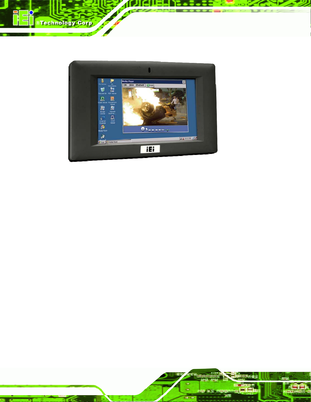
1.1 Overview
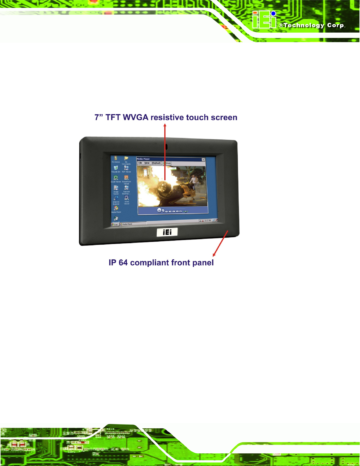
Figure 1-1: IOVU-751R-CE5/UX-R10
IOVU-751R-CE5/UX-R10 User Manual
The IOVU series industrial CE touch-screen open offers both the reliability of a traditional
and the flexibility of a PC. With an open, the user is able to run their own or third party
software. Furthermore, the IOVU series is designed for use as a thin client device in a
remote terminal environment. The IOVU series is powered by an open Windows CE .NET
5.0 OS with rich application development support and connectivity to network and I/O
devices.
The IOVU-751R-CE5/UX-R10 features a low power (less than 0.5 Watts) 500 MHz RMI
Alchemy™ Au1250™ media processor with an integrated media acceleration engine (MAE)
that supports MPEG 1, MPEG 2, MPEG 4, WMV 9 and DivX video file formats.
1.1.1 Benefits
Some of the IOVU-751R-CE5/UX-R10 benefits include:
An Open design to provide both open architectures for hardware and
software.
Designed to fill the gap between traditional products and industrial PCs to
Page 2
offer traditional reliability and PC flexibility.
Page 12
IOVU-751R-CE5/UX-R10 User Manual
Offers increased functionality and flexibility over traditional s at a lower cost
than industrial PCs.
Enables users to configure the product for a particular application by
accessing the operating system and scaling it to meet their needs.
Rugged, compact, operates over wide temperature variations, and low power
consumption embedded hardware design without failure-prone hard disk and
fan.
Standard peripheral connectors including Ethernet port, serial ports, USB
ports, Secure Digital memory, and touch input.
Open architecture to run user or third party application software.
Thin client device application in a remote terminal environment.
The Ethernet port helps system administrators secure and separate network
segments by field applications as well as communications to back-end legacy
systems and central databases.
Powered by popular open Windows CE. NET embedded hard real-time
operating system provides rich Windows-based functions and application
software development support.
PoE (Power over Ethernet) capability reduces communications and power
supply to a single CAT5e cable.
Utilities and Remote Management Tools make it easy to manage the IOVU
centrally and remotely.
1.1.2 Features
The IOVU-751R-CE5/UX-R10 features are listed below:
Embedded low power (less than 0.5 Watts) 500 MHz RMI Alchemy™
Au1250™ media processor
2 MB Boot Flash
On-board 256 MB DDR2
1 GB Secure Digital (SD) plug and play (PnP) storage
Supports MPEG 1, MPEG 2, MPEG 4 and WMV 9 video file formats
One high performance 10/100 Mb/s Ethernet connector
One high performance 10/100 Mb/s Ethernet connector with PoE (Power over
Ethernet) capability (complies with IEEE 802.3af PoE specifications)
Two USB 2.0 ports
Page 3
Page 13
One RS-232 serial communication connection
One RS-232/422/485 serial communication connection
Two 1.5 Watt speakers
7” color active matrix TFT display
4-wire resistive touch panel
6-30 VDC input
Cool grey frame
RoHS compliant
1.1.3 Technical Specifications
The IOVU-751R-CE5/UX-R10 technical specifications are listed in 196H196HTable 1-1.
SPECIFICATIONS
SYSTEM
IOVU-751R-CE5/UX-R10 User Manual
CPU
Memory
Real-time Clock
Watchdog Timer
Reset
DISPLAY
Display Type
Display Size
Resolution
Video Support
Brightness
Touch Panel
500 MHz RMI Alchemy™ Au1250™ media processor
2MB boot flash
256 MB DDR2
1 GB Secure Digital® card (internal)
Battery backup RTC
Software programmable supports 1~255 sec. system reset
Reset Button
Color active matrix TFT
7”
800 x 480, 262K color graphics
MPEG1, MPEG2, MPEG4, DivX, WMV9
500 cd/m
4-wired resistive touch panel
2
Page 4
I/O and COMMUNICATION
Ethernet
2 x 10/100 Mbps
Page 14
IOVU-751R-CE5/UX-R10 User Manual
SPECIFICATIONS
1 x RS-232
Serial Ports
1 x RS-232/422/485
USB Interfaces
Audio
POWER
Power Supply
Power Consumption
ENVIRONMENTAL and MECHANICAL
Operating Temperature
Humidity
Vibration
Front Panel Color
2 x USB 2.0 host connectors
2 x 1.5 Watt speakers
6-30 VDC
8.5 W
Minimum: -20ºC (-4°F)
Maximum: 60°C (140°F)
5%RH to 90%RH (non-condensing)
Operating Random Vibration Mode
1.Axes: 3 axes (Vertical / Transverse / Longitudinal).
2.10-500 Hz, 60min/axis.
3.Equivalent to Z:2.18 Grms X:1.6 Grms Y:1.96 Grms
Black C
Physical Dimensions
Ingress Protection
Table 1-1: Technical Specifications
1.2 Certifications
All IOVU-751R-CE5/UX-R10 series models comply with the following international
standards:
RoHS
IP 64
For a more detailed description of these standards, please refer to Appendix A.
312.5 mm x 242.6 mm x 65.1 mm (width x length x depth)
IP 64 compliant front panel
Page 5
Page 15
IOVU-751R-CE5/UX-R10 User Manual
Chapter
2
2 Detailed Specifications
Page 6
Page 16
IOVU-751R-CE5/UX-R10 User Manual
2.1 Mechanical Overview
2.1.1 Front Panel
The IOVU-751R-CE5/UX-R10 front panel (197H197HFigure 2-1) comprises a 7” TFT WVGA 16-bit
color touch screen LCD in an ABS+PC plastic frame.
Figure 2-1: Front Panel
2.1.2 Connector Panel
All external peripheral interface connectors are located on the bottom panel of the
IOVU-751R-CE5/UX-R10 . The peripheral interface connectors are shown in
198H198HFigure 2-2.
Page 7
Page 17

Figure 2-2: IOVU-751R-CE5/UX-R10 Peripheral Connectors
External peripheral interface connectors on the IOVU-751R-CE5/UX-R10 include:
1 x DC-IN power socket
1 x DC-IN bare wire terminal block
1 x Power switch
2 x RJ-45 LAN connectors (one supports PoE)
IOVU-751R-CE5/UX-R10 User Manual
1 x RS-232 connector
1 x RS-232/422/485 connector
2 x USB connectors
2.1.3 Physical Dimensions
The physical dimensions of the IOVU-751R-CE5/UX-R10 are shown in 199H199HFigure 2-3 and
listed below:
Front Panel: 226mm (W) x140mm (H) x 15.68mm (D)
Cabinet: 213.55mm (W) x 125.27mm (H) x 24mm (D)
Page 8
Page 18
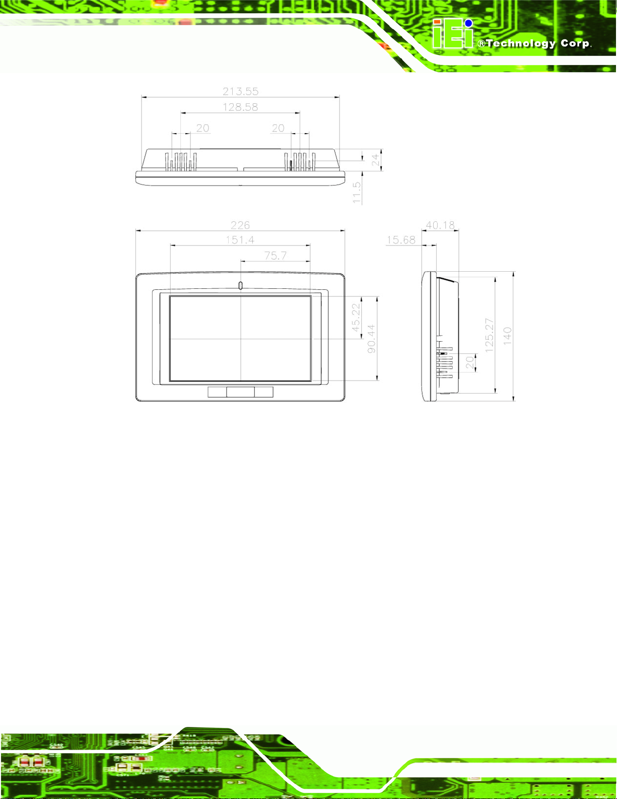
IOVU-751R-CE5/UX-R10 User Manual
Figure 2-3: IOVU-751R-CE5/UX-R10 Physical Dimensions (millimeters)
2.2 Internal Overview
Internally the IOVU-751R-CE5/UX-R10 has a KAMIO-1252 embedded RISC (reduced
instruction set computer) motherboard installed. An onboard Secure Digital card is also
preinstalled onto the KAMIO-1252.
Some of the specifications for the KAMIO-1252 are listed below. For more detailed
information, please refer to the KAMIO-1252 user manual.
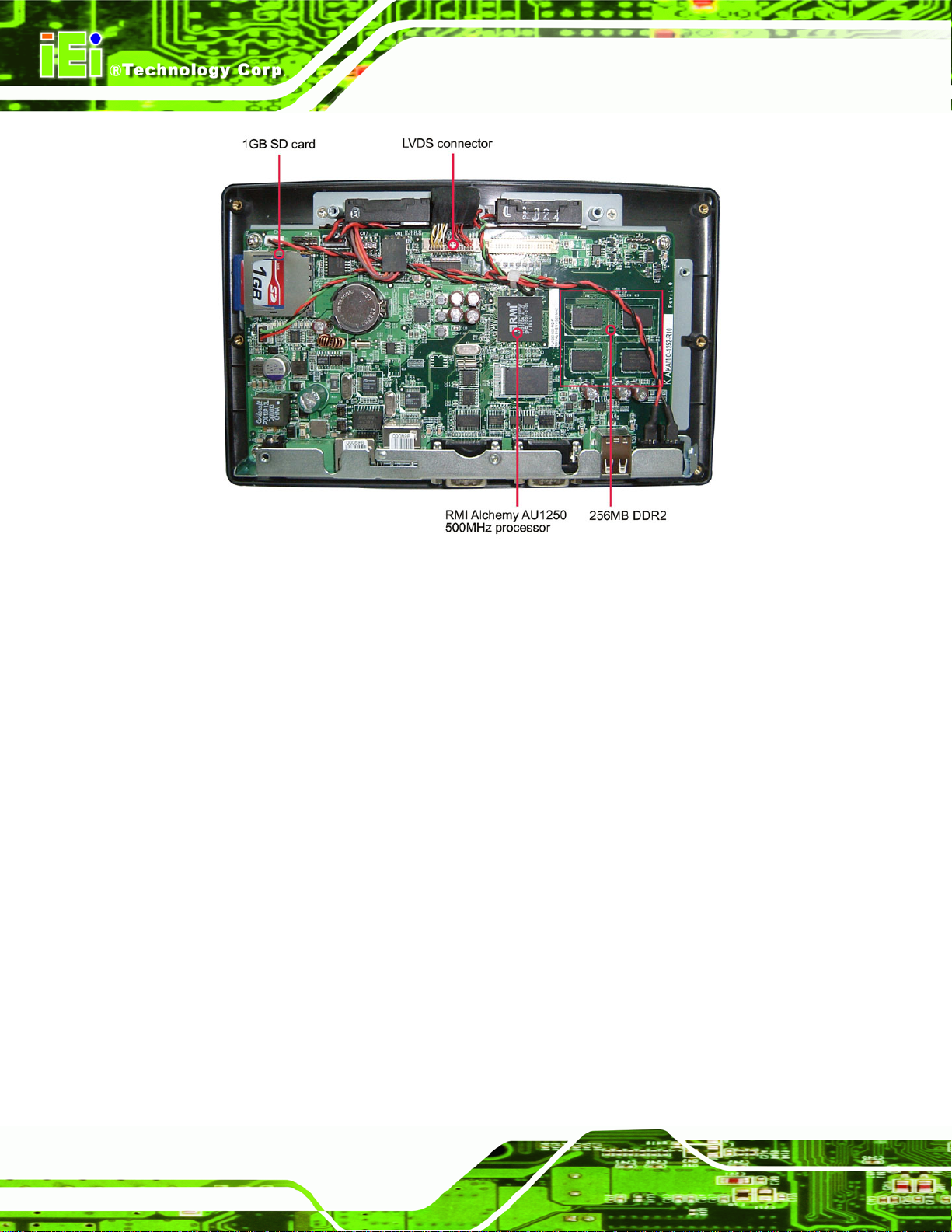
2.2.1 KAMIO-1252 Overview Photo
The KAMIO-1252 has a wide variety of internal and external peripheral connectors. A
labeled photo of the front side of the KAMIO-1252 is shown in
200H200HFigure 2-4.
Page 9
Page 19
IOVU-751R-CE5/UX-R10 User Manual
Figure 2-4: KAMIO-1252 Overview [Front View]
2.2.1.1 KAMIO-1252 Peripheral Connectors and Jumpers
The KAMIO-1252 has the following internal connectors and jumpers onboard:
1 x Audio connector
1 x Power LED connector
1 x Power switch connector
1 x PIC debug connector
1 x TTL LCD interface connector
1 x CPU JTAG connector
1 x LVDS LCD connector
1 x SD/SDIO/MMC connector
1 x Touch panel connector
1 x UIP debug connector
Page 10
1 x Speaker-out connector
The KAMIO-1252 has the following external peripheral interface connectors on the bottom
panel
Page 20
IOVU-751R-CE5/UX-R10 User Manual
1 x 10/100-BaseT Ethernet connector
1 x 10/100-BaseT Ethernet connector with PoE capability
1 x 12V DC-in power socket
1 x 6-30V DC-in bare wire terminal block
1 x RS-232 serial port connector
1 x RS-232/422/485 serial port connector
2 x USB port connectors
2.2.1.2 KAMIO-1252 Technical Specifications
KAMIO-1252 technical specifications are listed below.
Specification Value
System 500 MHz RMI Alchemy™ Au1250™
2 MB boot flash
256 MB DDR2
1 GB secure digital (SD) card for OS/Program storage
Battery backup RTC
Watchdog timer
Reset button
JTAG pin-header
Display Dual LCD Interface supports 24-bit single channel LVDS
and TTL LCD panel interface
24-bit color graphics resolutions up to 800 x 480 pixels
MPEG-1, MPEG-2, MPEG-4, WMV 9, and DivX support
4-wire touch resistive interface
I/O and
Communications
1 x 10/100 Mbps Ethernet port
1 x 10/100 Mbps Ethernet port with PoE capability
1 x RS-232 serial port
1 x RS-232/422/485 serial port (configured by software)
2 x USB 2.0 ports
Power 6-30 VDC input
Less than 8.5 W power consumption
Page 11
Page 21
Specification Value
Environmental -20ºC – 60ºC
Table 2-1: Technical Specifications
2.3 LCD Specifications
The IOVU-751R-CE5/UX-R10 has a 7” WVGA LCD screen. The LCD screen is attached
to an aluminum frame that is IP 64 compliant. The specifications are shown below.
Model DATA IMAGE FG0700A2DSSWBG02
Size 7”
Resolution 800 x 480 (WVGA)
IOVU-751R-CE5/UX-R10 User Manual
5% - 85% relative humidity (non-condensing)
IP64 compliant front panel
Active Area (mm) 152.4 x 91.44
Pixel Pitch (mm) 0.0635 x 0.1905
LCD Color Native 262K colors
View Angel (H/V) 140/100
Brightness (cd/m2) 500
Contrast Ratio 400:1
Response Time (ms) 5(Tr) / 15(Tf)
Supply Voltage (V) 3.3
Backlight 1 CCFL
Backlight MTBF (hrs.) 50000
Dimensions (mm) 165.0 x 104.0 x 5.5
Table 2-2: IOVU-751R-CE5/UX-R10 LCD Specifications
2.4 Touch Panel Specifications
The IOVU-751R-CE5/UX-R10 has a 4-wire touch screen installed. 201H201HTable 2-3 lists the
touch panel specifications.
Page 12
Touch screen
Type
EELY-ECW
4-wire
Page 22
IOVU-751R-CE5/UX-R10 User Manual
Touch screen
Resolution
Transmission
S/W driver
Keypad
Table 2-3: Touch Panel Specifications
2.5 Multimedia Capabilities
The IOVU-751R-CE5/UX-R10 supports video decode at the following resolutions
D1 (PAL, NTSC)
VGA
Wide VGA (16:9)
QVGA
GIF
EELY-ECW
Continuous
> 80%
Windows CE 5.0 or Linux
NO
W GIF (16:9)
The IOVU-751R-CE5/UX-R10 supports the following video formats:
MPEG-1
MPEG-2
WMV9
DivX
MPEG-4, MP4 and AVI
The IOVU-751R-CE5/UX-R10 supports the following audio formats:
MPEG
AAC
WMA
PCM
AC-3
OGG Vorbis
Page 13
Page 23
2.6 Power Supply
WARNING:
Whenever you need to remove a part for maintenance or upgrading,
switch off the power supply and unplug the power cord first.
The IOVU-751R-CE5/UX-R10 has a 12 V DC power input and a 6-30 V DC bare-wire
connector on the bottom panel. The IOVU-751R-CE5/UX-R10 also supports Power over
Ethernet (PoE) through one of its LAN ports.
IOVU-751R-CE5/UX-R10 User Manual
Page 14
Page 24
IOVU-751R-CE5/UX-R10 User Manual
Chapter
3
3 Unpacking
Page 15
Page 25

3.1 Anti-static Precautions
WARNING:
Failure to take ESD precautions during the installation of the
IOVU-751R-CE5/UX-R10 may result in permanent damage to the
IOVU-751R-CE5/UX-R10 and severe injury to the user.
Electrostatic discharge (ESD) can cause serious damage to electronic components,
including the IOVU-751R-CE5/UX-R10. Dry climates are especially susceptible to ESD. It
is therefore critical that whenever the IOVU-751R-CE5/UX-R10 or any other electrical
component is handled, the following anti-static precautions are strictly adhered to.
Wear an anti-static wristband: Wearing a simple anti-static wristband can
IOVU-751R-CE5/UX-R10 User Manual
help to prevent ESD from damaging the board.
Self-grounding: Before handling the board,
material. During the time the board is handled, frequently touch any
conducting materials that are connected to the ground.
Use an anti-static pad: When configuring the IOVU-751R-CE5/UX-R10,
place it on an antic-static pad. This reduces the possibility of ESD damaging
the IOVU-751R-CE5/UX-R10.
3.2 Unpacking
3.2.1 Unpacking Precautions
When the IOVU-751R-CE5/UX-R10 is unpacked, please do the following:
Follow the anti-static precautions outlined in Section
Make sure the packing box is facing upwards so the IOVU-751R-CE5/UX-R10
does not fall out of the box.
Make sure all the components shown in Section
touch any grounded conducting
202H202H3.1.
203H203H3.3 are present.
Page 16
Page 26

IOVU-751R-CE5/UX-R10 User Manual
3.3 Unpacking Checklist
NOTE:
If some of the components listed in the checklist below are missing,
please do not proceed with the installation. Contact the IEI reseller or
vendor you purchased the IOVU-751R-CE5/UX-R10 from or contact an
IEI sales representative directly. To contact an IEI sales representative,
please send an email to 98H98Hsales@iei.com.tw.
3.3.1 Package Contents
The IOVU-751R-CE5/UX-R10 is shipped with the following components:
Quantity Item and Part Number Image
1 IOVU-751R-CE5/UX-R10
1 Utility CD including SDK, utilities, and
technical documentation
1 Null modem cable
1 Touch pen
Table 3-1: Package List Contents
Page 17
Page 27

IOVU-751R-CE5/UX-R10 User Manual
3.4 Optional Items
Part Number Description Image
ALFPK-08 Panel mount kit
AFLWK-07 VESA 75 wall mount kit
ARM-11-RS LCD monitor/PPC arm kit, load
capacity of 3kg~7kg
STAND-A08-RS LCD monitor/PPC stand kit for VESA
75, up to 5kg
VSTAND-A07 LCD monitor/PPC stand V type for
VESA 75, 0~90 degree adjustable
hinge and up to 2.5kg capacity
AFLP-12BMSR-U USB magnetic card reader
AFLP-BRW01-U,
AFLPBRB01-U
USB barcode reader (white/black)
Page 18
Page 28

IOVU-751R-CE5/UX-R10 User Manual
Part Number Description Image
FLP-CDB01, AFLP-CDW01 VFD customer display (green) 5x7 dot
matrix (black/white)
63000-FSP060DBAB1555-RS 24V DC 45W power adapter with bare
wire, 90-264V AC input
IPS-2042TX Industrial 6-port Lite-Managed P.O.E.
Ethernet Switch with 6 x 10/100TX
AUPS-A10-R10 DC 12V input 60W UPS module with
Table 3-2: Optional Items
3800mAH, 2S2P Li-Ion battery, VESA
75
Page 19
Page 29

IOVU-751R-CE5/UX-R10 User Manual
Chapter
4
4 Installation
Page 20
Page 30

IOVU-751R-CE5/UX-R10 User Manual
4.1 Installation Precautions
When installing the IOVU-751R-CE5/UX-R10, please follow the precautions listed below:
Read the user manual: The user manual provides a complete description of
the IOVU-751R-CE5/UX-R10, installation instructions and configuration
options.
DANGER! Disconnect Power: Power to the IOVU-751R-CE5/UX-R10 must
be disconnected during the installation process, or before any attempt is
made to access the rear panel. Electric shock and personal injury might occur
if the rear panel of the IOVU-751R-CE5/UX-R10 is opened while the power
cord is still connected to an electrical outlet.
Qualified Personnel: The IOVU-751R-CE5/UX-R10 must be installed and
operated only by trained and qualified personnel. Maintenance, upgrades, or
repairs may only be carried out by qualified personnel who are familiar with
the associated dangers.
Mounting: It is advisable at least two people assist with mounting the
IOVU-751R-CE5/UX-R10.
Air Circulation: Make sure there is sufficient air circulation when installing
the IOVU-751R-CE5/UX-R10. The IOVU-751R-CE5/UX-R10’s cooling vents
must not be obstructed by any objects. Blocking the vents can cause
overheating of the IOVU-751R-CE5/UX-R10. Leave at least 5 cm of
clearance around the IOVU-751R-CE5/UX-R10 to prevent overheating.
Grounding: The IOVU-751R-CE5/UX-R10 should be properly grounded. The
voltage feeds must not be overloaded. Adjust the cabling and provide external
overcharge protection per the electrical values indicated on the label attached
to the back of the IOVU-751R-CE5/UX-R10.
4.2 External Peripheral Interface Connectors
204H204HTable 4-1 lists the external interface connectors on the IOVU-751R-CE5/UX-R10.
Detailed descriptions of the connectors can be found following the table.
Page 21
Page 31

IOVU-751R-CE5/UX-R10 User Manual
Connector Type
6-30V DC power jack DC Jack
6-30V DC bare wire power terminal Terminal Block
Ethernet connectors RJ-45 Jack connector
Power switch On/off switch
RS-232 D-sub 9 Male connector
RS-232/422/485 Serial connector D-sub 9 Male connector
USB connectors Dual USB port
Table 4-1: External Interface Connectors
Figure 4-1: IOVU-751R-CE5/UX-R10 Peripheral Connectors
4.2.1 DC Power interfaces
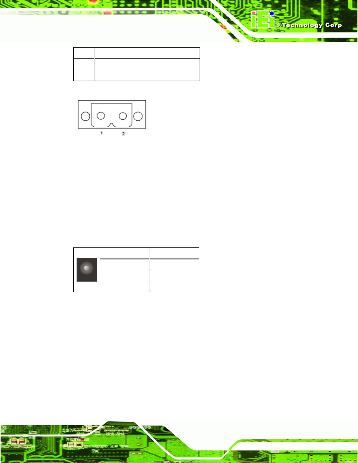
4.2.1.1 6V~30V DC Terminal Block
The power terminal block connects to a 6V~30V DC power source.
Page 22
CN Label: CN12
CN Type:
CN Location:
CN Pinouts:
Terminal block
205H205HFigure 4-1
See
206H206HTable 4-2 and 207H207HFigure 4-2
See
Page 32
IOVU-751R-CE5/UX-R10 User Manual
PIN DESCRIPTION
1 6~30V DC Power in
2 GND
Table 4-2: 9~36V Power Connector Pinouts
Figure 4-2: Power Terminal Block
4.2.1.2 12V DC-In
Use the rear panel +6-30V DC jack to connect the monitor to a power source.
CN Label:
CN Type: 6-30V DC Jack
CN Pinouts:
CN Location:
CN13
208H208HTable 4-3
See
209H209HFigure 4-1
See
PIN DESCRIPTION
1 GND
2 GND
3 +6-30V
Table 4-3: DC 6-30V Connector Pinouts
4.2.2 Serial Interfaces
The system has both a RS-232 and a RS-232/422/485 serial port connector.
4.2.2.1 RS-232 Serial Interface Pinouts
Pinouts for the RS-232 serial port are shown below.
Page 23
Page 33
Pin Arrangement Pin No Signal Name Direction Description
1 DCD Input Carrier Detect
2 RX Input Receive D ata
3 TX Output Send Data
4 DTR Output Data Terminal Ready
5 GND N/A Ground
6 DSR Input Data Set Ready
7 RTS Output Request to Send
8 CTS Input Send Possible
9 RI Input Called Status Display
Shell FG N/A Frame Ground
IOVU-751R-CE5/UX-R10 User Manual
(Common with SG)
Table 4-4: RS-232 Pinouts
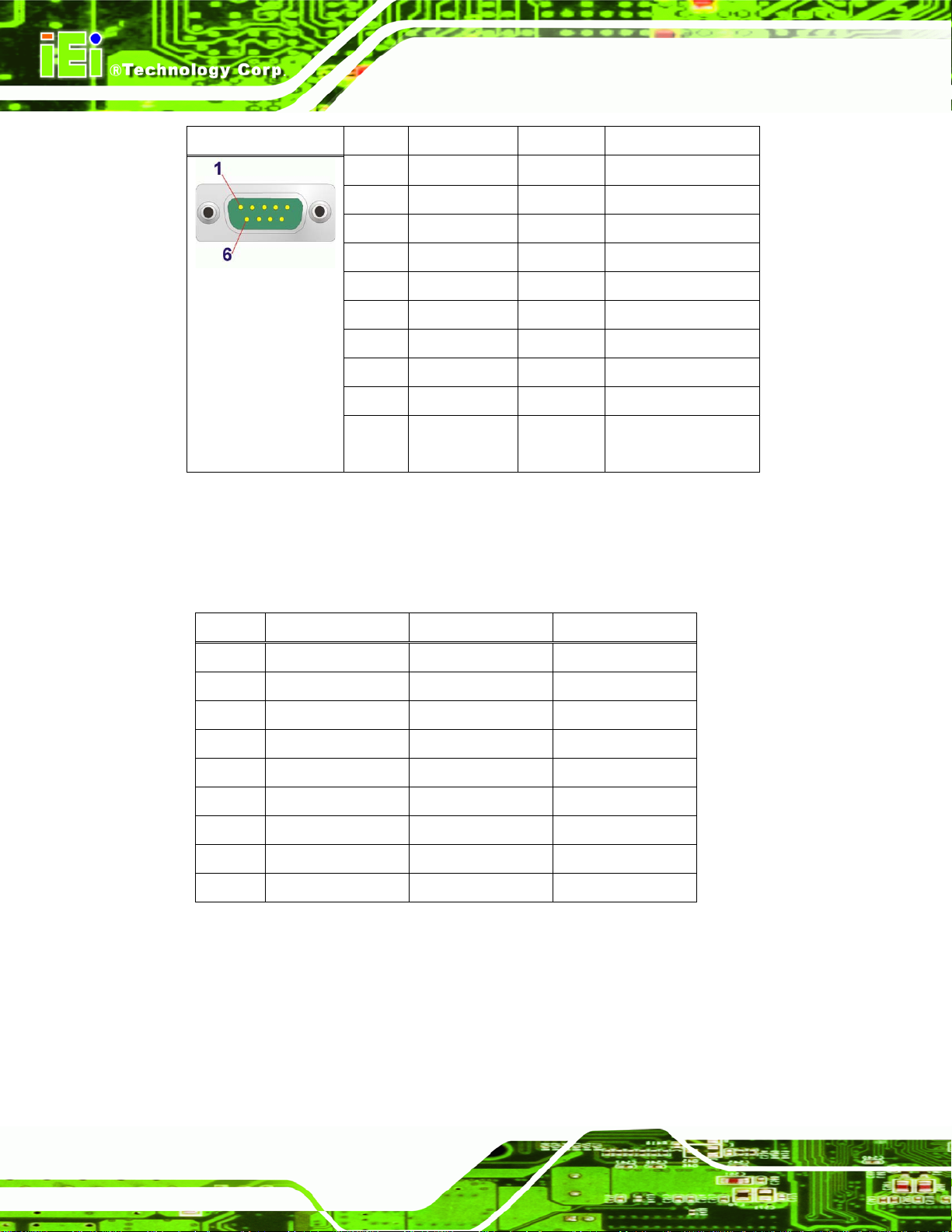
4.2.2.2 RS-232/422/485 Serial Interface Pinouts
Pinouts for the RS-232/422/485 serial port are shown below.
Pin RS-232 RS-422 RS-485
1 RX- DATA2 RX RX+ DATA+
3 TX TX-
4
5 GND GND GND
6
7 TX+
8
9
Table 4-5: Serial Port Pinouts
Page 24
Page 34
IOVU-751R-CE5/UX-R10 User Manual
Figure 4–3: Serial Port Pinouts
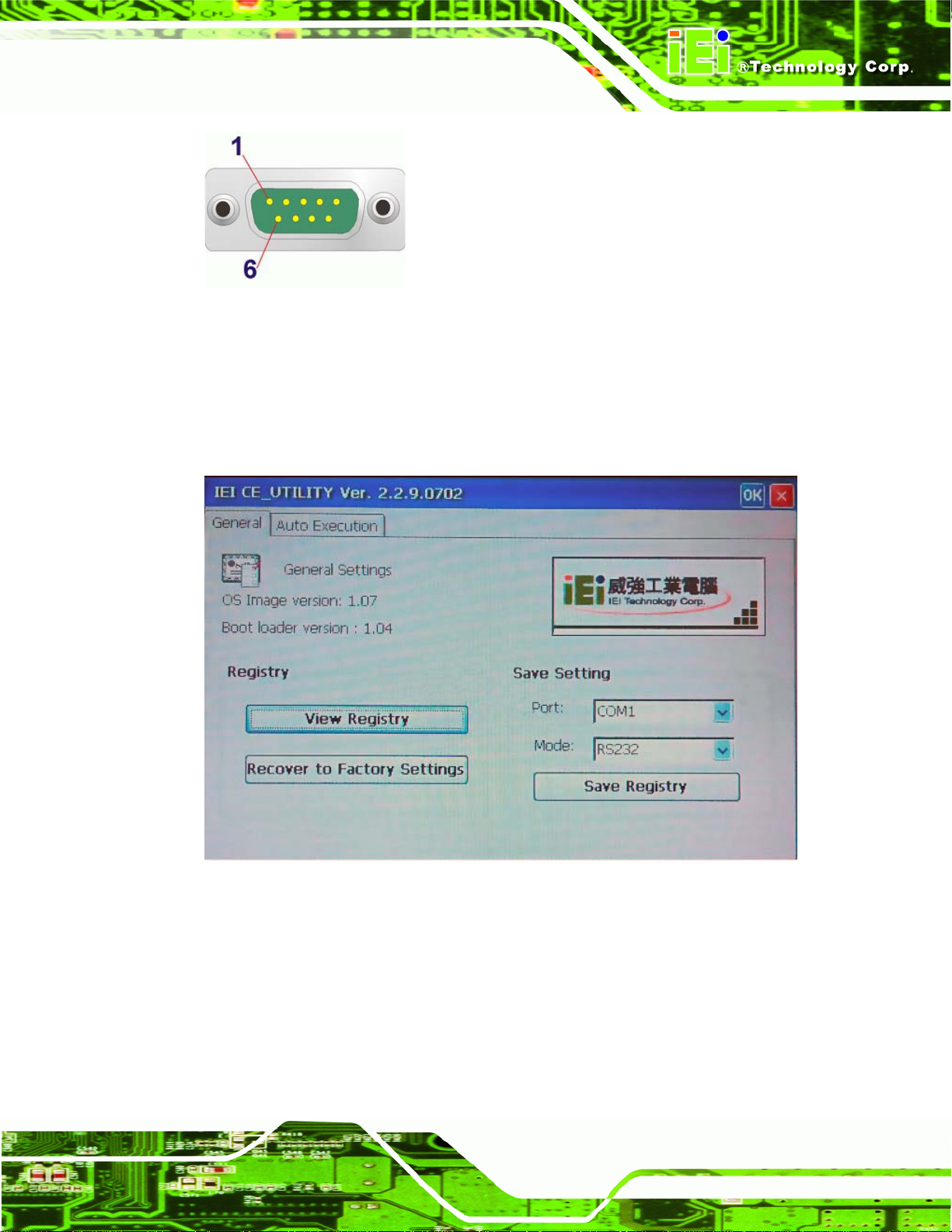
To select RS-232, RS-422, or RS-485 mode, please follow the directions below.
Step 1: Select "Start > Programs > IEI > IEI CEUTILITY.exe" to run IEI_CEUTILITY.exe
in the “SYSTEM” folder on the SD/CF card).
Figure 4-4: Serial Port Mode Setting
Step 2: Change serial port mode setting. Change the value in
210H210HFigure 4-4 to the
desired mode setting.
Step 3: Click "Set"
Step 4: Click "Save Registry" to save the changes.
Step 0:
Page 25
Page 35
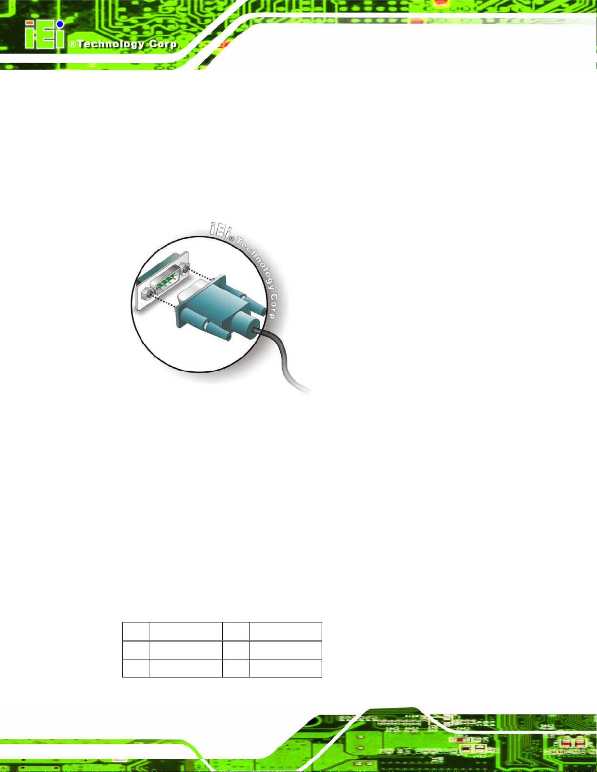
4.2.2.3 Connecting the Serial Port
The IOVU-751R-CE5/UX-R10 has two female DB-9 connectors on the external peripheral
interface panel for a serial device. Follow the steps below to connect a serial device to the
IOVU-751R-CE5/UX-R10.
Step 1: Insert the serial connector. Insert the DB-9 connector of a serial device into
IOVU-751R-CE5/UX-R10 User Manual
the DB-9 connector on the external peripheral interface. See
211H211HFigure 4-5.
Figure 4-5: Serial Device Connector
Step 2: Secure the connector. Secure the serial device connector to the external
interface by tightening the two retention screws on either side of the connector.
Step 0:
4.2.3 USB Connectors
4.2.3.1 USB Pinouts
USB devices connect directly to the USB connectors on the external peripheral connector
panel.
PIN DESCRIPTION PIN DESCRIPTION
1 VCC 5 VCC
2 D1- 6 D2-
Page 26
Page 36
IOVU-751R-CE5/UX-R10 User Manual
PIN DESCRIPTION PIN DESCRIPTION
3 D1+ 7 D2+
4 GND 8 GND
Table 4-6: USB Connector Pinouts
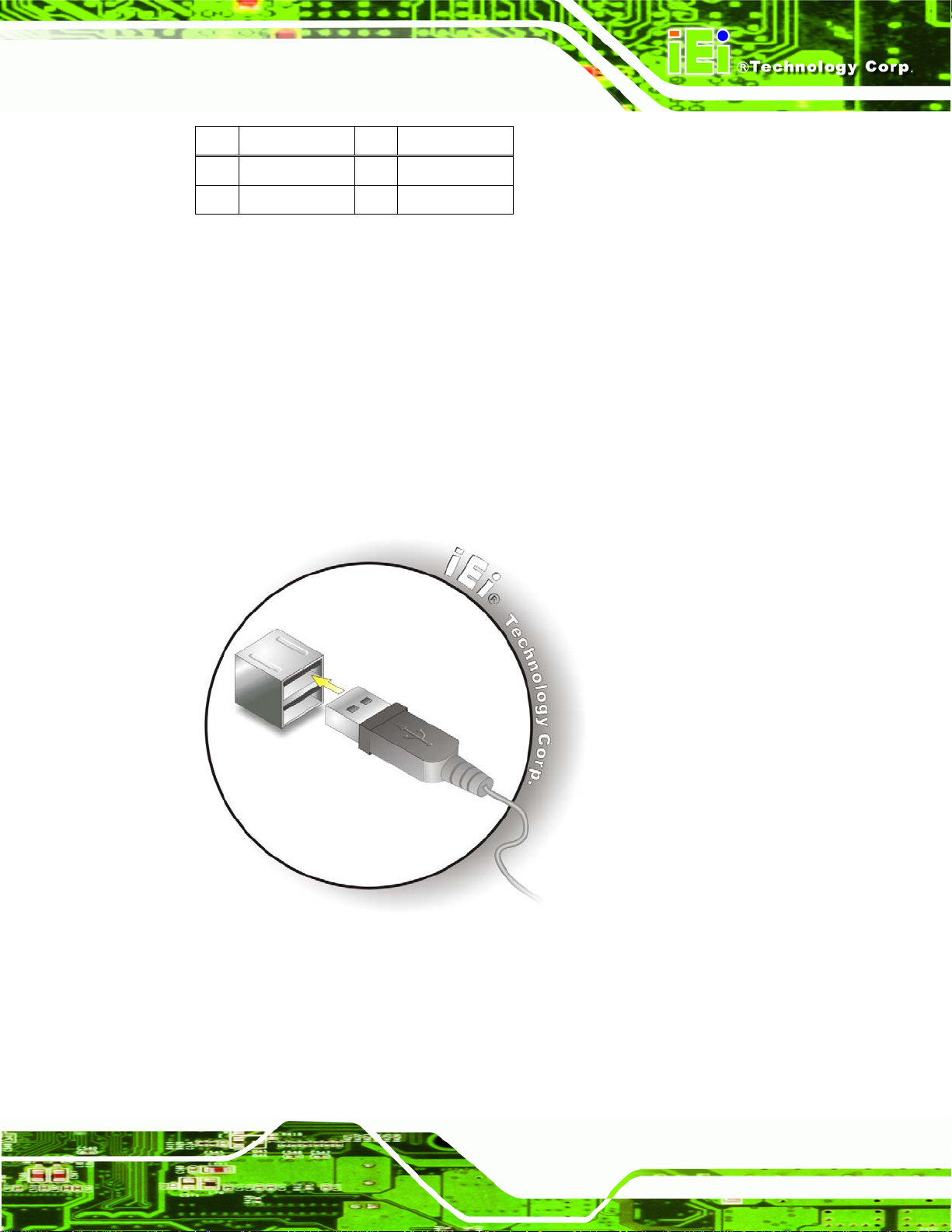
4.2.3.2 USB Connection (Dual Connector)
The external USB Series "A" receptacle connectors provide easier and quicker access to
external USB devices. Follow the steps below to connect USB devices to the
IOVU-751R-CE5/UX-R10.
Step 1: Insert a USB Series "A" plug. Insert the USB Series "A" plug of a device into
the USB Series "A" receptacle on the external peripheral interface. See
4-6.
212H212HFigure
Figure 4-6: USB Connector
4.2.4 Ethernet Connector
A 10/100Mb/s connection can be made between the Ethernet connectors and a Local
Area Network (LAN) through a network hub.
Page 27
Page 37
4.2.4.1 Ethernet Connector Pinouts
The Ethernet connector pinouts are shown below.
PIN DESCRIPTION
1 TPT+
2 TPT3 TPR+
4 LAN_GND
5 LAN_GND
6 TPR7 LAN_GND
8 LAN_GND
Table 4-7: Ethernet Connector Pinouts
IOVU-751R-CE5/UX-R10 User Manual
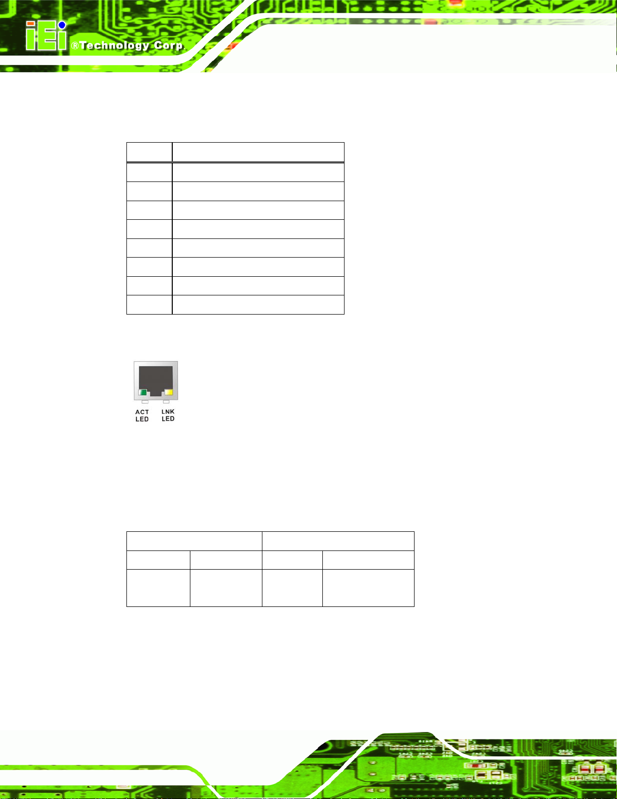
Figure 4-7: Ethernet Connector
The RJ-45 Ethernet connector has two status LEDs, one green and one yellow. The green
LED indicates activity on the port and the yellow LED indicates the port is linked (
4-8).
SPEED LED LINK LED
Status Description Status Description
GREEN ON: 100MB
OFF: 10MB
YELLOW ON: Linked
Flashing: Activity
Table 4-8: Ethernet Connector LEDs
213H213HTable
Page 28
Page 38
IOVU-751R-CE5/UX-R10 User Manual
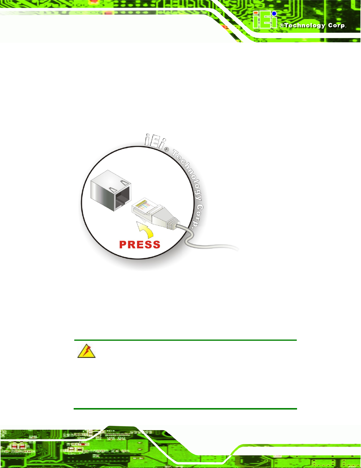
4.2.4.2 LAN Connection
There are two external RJ-45 LAN connectors. The RJ-45 connectors enable connection
to an external network. To connect a LAN cable with an RJ-45 connector, please follow
the instructions below.
Step 1: Align the connectors. Align the RJ-45 connector on the LAN cable with one of
the RJ-45 connectors on the IOVU-751R-CE5/UX-R10. See
Figure 4-8: LAN Connection
214H214HFigure 4-8.
Step 2: Insert the LAN cable RJ-45 connector. Once aligned, gently insert the LAN
cable RJ-45 connector into the on-board RJ-45 connector. Step 0:
4.3 Mounting the System
WARNING!
When mounting the flat panel PC onto an arm, onto the wall or onto a
panel, it is better to have more than one person to help with the installation
to make sure the panel PC does not fall down and get damaged.
Page 29
Page 39

Three methods of mounting the IOVU-751R-CE5/UX-R10 are listed below.
Wall mounting
Panel mounting
Arm mounting
The three mounting methods are described below.
4.3.1 Wall Mounting
To mount the IOVU-751R onto the wall, please follow the steps below.
Step 1: Select the location on the wall for the wall-mounting bracket.
Step 2: Carefully mark the locations of the four screw holes in the bracket on the wall.
Step 3: Drill four pilot holes at the marked locations on the wall for the bracket retention
IOVU-751R-CE5/UX-R10 User Manual
screws.
Step 4: Align the wall-mounting bracket screw holes with the pilot holes.
Step 5: Secure the mounting-bracket to the wall by inserting the retention screws into
the four pilot holes and tightening them (
215H215HFigure 4-9).
Page 30
Figure 4-9: Wall-mounting Bracket
Page 40
IOVU-751R-CE5/UX-R10 User Manual
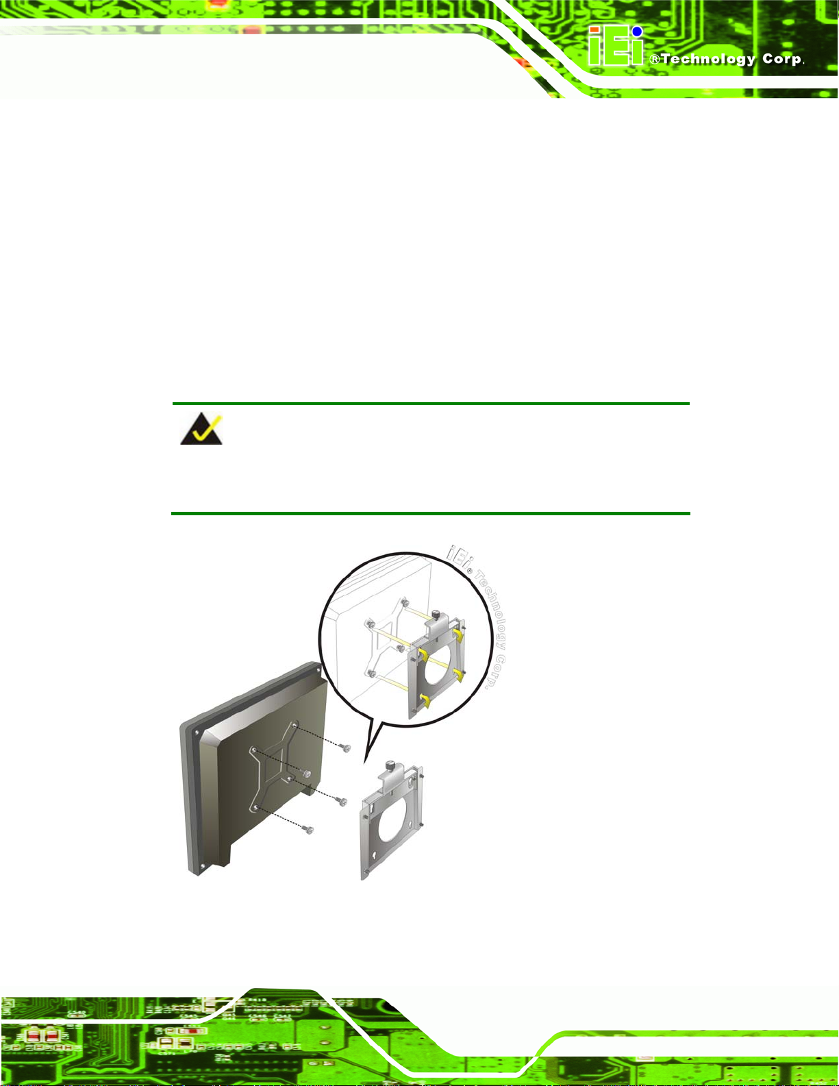
Step 6: Insert the four monitor mounting screws provided in the wall mounting kit into the
four screw holes on the real panel of the IOVU-751R and tighten until the screw
shank is secured against the rear panel (
216H216HFigure 4-10).
Step 7: Align the mounting screws on the monitor rear panel with the mounting holes on
the bracket.
Step 8: Carefully insert the screws through the holes and gently pull the monitor
downwards until the monitor rests securely in the slotted holes (
217H217HFigure 4-10).
Ensure that all four of the mounting screws fit snuggly into their respective
slotted holes.
NOTE:
In the diagram below the bracket is already installed on the wall.
Figure 4-10: Chassis Support Screws
Page 31
Page 41

Step 9: Secure the panel PC by fastening the retention screw of the wall-mounting
IOVU-751R-CE5/UX-R10 User Manual
bracket. (
Figure 4-11: Secure the IOVU-751R
218H218HFigure 4-11).
4.3.2 Panel Mounting
The IOVU-751R-CE5/UX-R10 can be mounted in a panel.
CAUTION:
When mounting the IOVU-751R-CE5/UX-R10 take care to tighten the
retention screws or bolts until fully secure, but do not over tighten. Over
tightening the retention screws or bolts may cause them to become
stripped, rendering them useless.
To mount the IOVU-751R-CE5/UX-R10 into a panel, please follow the steps below.
Step 1: Select the position on the panel to mount the IOVU-751R-CE5/UX-R10.
Page 32
Page 42

IOVU-751R-CE5/UX-R10 User Manual
Step 2: Cut out a section from the panel that corresponds to the rear panel dimensions
of the IOVU-751R-CE5/UX-R10. Take care that the panel section that is cut out
is smaller than the overall size of the frame that surrounds the IOVU-751R but
just large enough for the rear panel of the IOVU-751R to fit through (see
4-12).
Figure 4-12: IOVU-751R-CE5/UX-R10 Panel Opening (mm)
219H219HFigure
Step 3: Slide theIOVU-751R-CE5/UX-R10 through the hole until the frame is flush
against the panel.
Step 4: Insert the panel mounting clamps into the pre-formed holes along the edges of
the chassis, behind the frame.
Figure 4-13: Panel Mounting Clamps
Page 33
Page 43

Step 5: Tighten the screws that pass through the panel mounting clamps until the plastic
IOVU-751R-CE5/UX-R10 User Manual
caps at the front of all the screws are firmly secured to the panel (
Figure 4-14: Tighten the Panel Mounting Clamp Screws
220H220HFigure 4-14).
4.3.3 Arm Mounting
The IOVU-751R-CE5/UX-R10 is VESA (Video Electronics Standards Association)
compliant and can be mounted on an arm with a 75 mm interface pad. To mount the
IOVU-751R-CE5/UX-R10 on an arm, please follow the steps below.
Step 1: The arm is a separately purchased item. Please correctly mount the arm onto
the surface it uses as a base. To do this, refer to the installation documentation
that came with the mounting arm.
NOTE:
When purchasing the arm please ensure that it is VESA compliant and that
the arm has a 75 mm interface pad. If the mounting arm is not VESA
compliant it cannot be used to support the IOVU-751R-CE5/UX-R10.
Page 34
Page 44

IOVU-751R-CE5/UX-R10 User Manual
Step 2: Once the mounting arm has been firmly attached to the surface, lift the
IOVU-751R onto the interface pad of the mounting arm.
Step 3: Align the retention screw holes on the mounting arm interface with those on
theIOVU-751R, as shown in
221H221HFigure 4-15.
Figure 4-15: Arm Mounting Retention Screw Holes
Step 4: Secure the IOVU-751R to the interface pad by inserting four retention screws
through the bottom of the mounting arm interface pad and into the IOVU-751R.
Step 0:
Figure 4-16: Arm Mounting (ARM-11-RS)
Page 35
Page 45

4.3.4 Stand Mounting
The IOVU-751R has Video Electronics Standards Association (VESA) standard mounting
holes tapped into the rear panel. The monitor stand mounting plate has a matching VESA
hole pattern. To mount the IOVU onto a stand, please follow the steps below.
Step 1: Line up the threaded holes on the monitor rear panel with the screw holes on the
monitor stand mounting plate.
IOVU-751R-CE5/UX-R10 User Manual
Step 2: Secure the monitor to the stand with the supplied retention screws (
4-17).Step 0:
Figure 4-17: Stand Mounting
222H222HFigure
4.4 Software
The IOVU-751R-CE5/UX-R10 comes with a pre-installed Windows CE 5.0 or Linux 2.6.x
operating system and a rich software application development kit. For information about
configuring the operating system, adding remote management tools or additional software
and drivers, refer to the user manuals on IEI IOVU Utility CD that came with the
IOVU-751R-CE5/UX-R10. The IOVU includes the following software:
Page 36
Page 46

IOVU-751R-CE5/UX-R10 User Manual
IOVU-751R-CE5/-R10:
Standard Windows® CE5.0 professional version license.
Optional Board Support Package (BSP) for customers to customize their own
OS image.
Attached Software Development Kit (SDK) for embedded Visual C++ to
program Windows CE application.
Built-in .NET Compact Framework support with related SDK
Thin Client Technology, Microsoft RDP (Remote Desktop Protocol), to enable
IOVU-751R to access Microsoft Windows® based applications installed on
Microsoft Terminal Service server.
Free pre-installed utilities for configuring and diagnosing your IOVU-751R.
Free remote management tools installed in laptop for remotely configuring,
monitoring, and managing your IOVU-751R.
IOVU-751R-UX/-R10:
GNU standard Embedded Linux 2.6.x bootloader and OS image
Secure Shell (OpenSSH) providing 128-bit, 192-bit or 256-bit encryption
between the IOVU-751R and another system
Built-in web browser and X-window system
Related Linux drivers for onboard peripheral I/O, network and audio
Attached SDK including GUI, Sample Code, and Tool chain make users
program application readily.
Optional Board Support Package (BSP) including kernel source code for
customers to customize their own OS image.
Page 37
Page 47

IOVU-751R-CE5/UX-R10 User Manual
Appendix
A
A Certifications
Page 38
Page 48

IOVU-751R-CE5/UX-R10 User Manual
A.1 RoHS Compliant
All models in the IOVU series comply with the Restriction of Hazardous Materials (RoHS)
Directive. This means that all components used to build the industrial workstations and the
workstation itself are RoHS compliant.
The RoHS Directive bans the placing on the EU market of new electrical and electronic
equipment containing more than agreed levels of lead, cadmium, mercury, hexavalent
chromium, polybrominated biphenyl (PBB) and polybrominated diphenyl ether (PBDE)
flame retardants.
A.2 IP 64 Compliant Front Panel
The front panels on all models in the IOVU series have an ingress protection rating (IP) of
64, IP 64 or greater. The front panels are protected from dust particles and splashed
water.
Page 39
Page 49

IOVU-751R-CE5/UX-R10 User Manual
Appendix
B
B Safety Precautions
Page 40
Page 50
IOVU-751R-CE5/UX-R10 User Manual
B.1 Safety Precautions
WARNING:
The precautions outlined in this appendix should be strictly followed.
Failure to follow these precautions may result in permanent damage to
the IOVU-751R-CE5/UX-R10.
Please follow the safety precautions outlined in the sections that follow:
B.1.1 General Safety Precautions
Please ensure the following safety precautions are adhered to at all times.
Make sure the power is turned off and the power cord is disco nnected
whenever the IOVU-751R-CE5/UX-R10 is being installed, moved or modified.
Do not apply voltage levels that exceed the specified voltage range.
Doing so may cause fire and/or an electrical shock.
Electric shocks can occur if the IOVU-751R-CE5/UX-R10 chassis is
opened when the IOVU-751R-CE5/UX-R10 is running.
Do not drop or insert any objects into the ventilation openings of the
IOVU-751R-CE5/UX-R10.
If considerable amounts of dust, water, or fluids enter the
IOVU-751R-CE5/UX-R10, turn off the power supply immediately, unplug the
power cord, and contact the IOVU-751R-CE5/UX-R10 vendor.
DO NOT:
o Drop the IOVU-751R-CE5/UX-R10 against a hard surface.
o Strike or exert excessive force onto the LCD panel.
o Touch any of the LCD panels with a sharp object
o In a site where the ambient temperature exceeds the rated temperature
Page 41
Page 51
B.1.2 Anti-static Precautions
WARNING:
Failure to take ESD precautions during the installation of the
IOVU-751R-CE5/UX-R10 may result in permanent damage to the
IOVU-751R-CE5/UX-R10 and severe injury to the user.
Electrostatic discharge (ESD) can cause serious damage to electronic components,
including the IOVU-751R-CE5/UX-R10. Dry climates are especially susceptible to ESD. It
is therefore critical that whenever the IOVU-751R-CE5/UX-R10 is opened and any of the
electrical components are handled, the following anti-static precautions are strictly
adhered to.
IOVU-751R-CE5/UX-R10 User Manual
Wear an anti-static wristband: Wearing a simple anti-static wristband can
help to prevent ESD from damaging any electrical component.
Self-grounding: Before handling any electrical component, touch any
grounded conducting material. During the time the electrical component is
handled, frequently touch any conducting materials that are connected to the
ground.
Use an anti-static pad: When configuring or working with an electrical
component, place it on an antic-static pad. This reduces the possibility of ESD
damage.
Only handle the edges of the electrical component: When handling the
electrical component, hold the electrical component by its edges.
Page 42
Page 52
IOVU-751R-CE5/UX-R10 User Manual
B.1.3 Product Disposal
WARNING:
Risk of explosion if battery is replaced by and incorrect type. Only
certified engineers should replace the on-board battery.
Dispose of used batteries according to instructions and local
regulations.
Outside the European Union - If you wish to dispose of used electrical and
electronic products outside the European Union, please contact your local
authority so as to comply with the correct disposal method.
Within the European Union:
EU-wide legislation, as implemented in each Member State, requires that
waste electrical and electronic products carrying the mark (left) must be
disposed of separately from normal household waste. This includes
monitors and electrical accessories, such as signal cables or power cords.
When you need to dispose of your display products, please follow the
guidance of your local authority, or ask the shop where you purchased the product. The
mark on electrical and electronic products only applies to the current European Union
Member States.
Please follow the national guidelines for electrical and electronic product disposal.
B.2 Maintenance and Cleaning Precautions
When maintaining or cleaning the IOVU-751R-CE5/UX-R10, please follow the guidelines
below.
B.2.1 Maintenance and Cleaning
Prior to cleaning any part or component of the IOVU-751R-CE5/UX-R10, please read the
details below.
Page 43
Page 53

Except for the LCD panel, never spray or squirt liquids directly onto any other
components. To clean the LCD panel, gently wipe it with a piece of soft dry
cloth or a slightly moistened cloth.
The interior of the IOVU-751R-CE5/UX-R10 does not require cleaning. Keep
fluids away from the IOVU-751R-CE5/UX-R10 interior.
Be cautious of all small removable components when vacuuming the
IOVU-751R-CE5/UX-R10.
Turn the IOVU-751R-CE5/UX-R10 off before cleaning the
IOVU-751R-CE5/UX-R10.
Never drop any objects or liquids through the openings of the
IOVU-751R-CE5/UX-R10.
Be cautious of any possible allergic reactions to solvents or chemicals used
when cleaning the IOVU-751R-CE5/UX-R10.
Avoid eating, drinking and smoking within vicinity of the
IOVU-751R-CE5/UX-R10 User Manual
IOVU-751R-CE5/UX-R10.
B.2.2 Cleaning Tools
Some components in the IOVU-751R-CE5/UX-R10 may only be cleaned using a product
specifically designed for the purpose. In such case, the product will be explicitly mentioned
in the cleaning tips. Below is a list of items to use when cleaning the
IOVU-751R-CE5/UX-R10.
Cloth – Although paper towels or tissues can be used, a soft, clean piece of
cloth is recommended when cleaning the IOVU-751R-CE5/UX-R10.
Water or rubbing alcohol – A cloth moistened with water or rubbing alcohol
can be used to clean the IOVU-751R-CE5/UX-R10.
Using solvents – The use of solvents is not recommended when cleaning the
IOVU-751R-CE5/UX-R10 as they may damage the plastic parts.
Vacuum cleaner – Using a vacuum specifically designed for computers is
one of the best methods of cleaning the IOVU-751R-CE5/UX-R10. Dust and
dirt can restrict the airflow in the IOVU-751R-CE5/UX-R10 and cause its
Page 44
circuitry to corrode.
Cotton swabs - Cotton swaps moistened with rubbing alcohol or water are
excellent tools for wiping hard to reach areas.
Page 54

IOVU-751R-CE5/UX-R10 User Manual
Foam swabs - Whenever possible, it is best to use lint free swabs such as
foam swabs for cleaning.
Page 45
Page 55

IOVU-751R-CE5/UX-R10 User Manual
Appendix
C
C Hazardous Materials
Disclosure
Page 46
Page 56

IOVU-751R-CE5/UX-R10 User Manual
C.1 Hazardous Materials Disclosure Table for IPB Products
Certified as RoHS Compliant Under 2002/95/EC Without
Mercury
The details provided in this appendix are to ensure that the product is compliant with the
Peoples Republic of China (China) RoHS standards. The table below acknowledges the
presences of small quantities of certain materials in the product, and is applicable to China
RoHS only.
A label will be placed on each product to indicate the estimated “Environmentally Friendly
Use Period” (EFUP). This is an estimate of the number of years that these substances
would “not leak out or undergo abrupt change.” This product may contain replaceable
sub-assemblies/components which have a shorter EFUP such as batteries and lamps.
These components will be separately marked.
Please refer to the table on the next page.
Page 47
Page 57
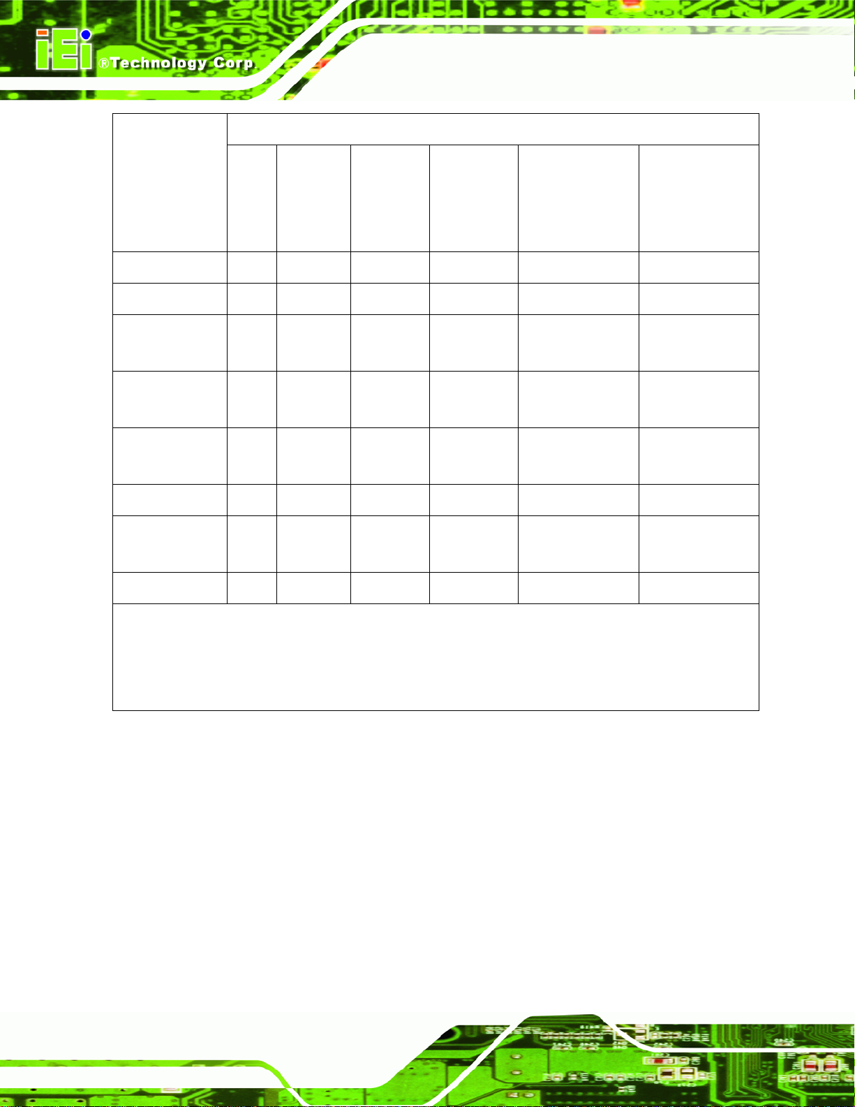
Toxic or Hazardous Substances and Elements Part Name
IOVU-751R-CE5/UX-R10 User Manual
Housing
Display
Printed Circuit
Board
Metal
Fasteners
Cable
Assembly
Fan Assembly
Power Supply
Assemblies
Lead
(Pb)
X O O O O X
X O O O O X
X O O O O X
X O O O O O
X O O O O X
X O O O O X
X O O O O X
Mercury
(Hg)
Cadmium
(Cd)
Hexavalent
Chromium
(CR(VI))
Polybrominated
Biphenyls
(PBB)
Polybrominated
Diphenyl
Ethers
(PBDE)
Battery
O: This toxic or hazardous substance is contained in all of the homogeneous materials for the part is
below the limit requirement in SJ/T11363-2006
X: This toxic or hazardous substance is contained in at least one of the homogeneous materials for
this part is above the limit requirement in SJ/T11363-2006
O O O O O O
Page 48
Page 58

IOVU-751R-CE5/UX-R10 User Manual
此附件旨在确保本产品符合中国 RoHS 标准。以下表格标示此产品中某有毒物质的含量符
合中国 RoHS 标准规定的限量要求。
本产品上会附有”环境友好使用期限”的标签,此期限是估算这些物质”不会有泄漏或突变”的
年限。本产品可能包含有较短的环境友好使用期限的可替换元件,像是电池或灯管,这些元
件将会单独标示出来。
有毒有害物质或元素 部件名称
铅
(Pb)
壳体
显示
印刷电路板
金属螺帽
电缆组装
风扇组装
电力供应组装
电池
O: 表示该有毒有害物质在该部件所有物质材料中的含量均在 SJ/T11363-2006 标准规定的限量要求以下。
X: 表示该有毒有害物质至少在该部件的某一均质材料中的含量超出 SJ/T11363-2006 标准规定的限量要求。
X O O O O X
X O O O O X
X O O O O X
X O O O O O
X O O O O X
X O O O O X
X O O O O X
O O O O O O
汞
(Hg)
镉
(Cd)
六价铬
(CR(VI))
多溴联苯
(PBB)
多溴二苯
醚
(PBDE)
Page 49
 Loading...