

Page 1

IEM-9452 ETX Module
IEM-9452 EXT Module
Page i
Page 2

IEM-9452 ETX Module
Revision
Date Version Changes
2008-03 1.00 Initial release
Page ii
Page 3

IEM-9452 ETX Module
COPYRIGHT NOTICE
The information in this document is subject to change without prior notice in order to
improve reliability, design and function and does not represent a commitment on the part
of the manufacturer.
In no event will the manufacturer be liable for direct, indirect, special, incidental, or
consequential damages arising out of the use or inability to use the product or
documentation, even if advised of the possibility of such damages.
Copyright
This document contains proprietary information protected by copyright. All rights are
reserved. No part of this manual may be reproduced by any mechanical, electronic, or
other means in any form without prior written permission of the manufacturer.
TRADEMARKS
All trademarks are registered trademarks of their parent organizations. Other product
names mentioned herein are used for identification purposes only and m ay be trademar ks
and/or registered trademarks of their respective owners.
Page iii
Page 4

IEM-9452 ETX Module
Manual Conventions
WARNING!
Warnings appear where overlooked details may cause damage to the equipment or result
in personal injury. Warnings should be taken seriously. Warnings are easy to recognize.
The word “warning” is written as “WARNING,” both capitalized and bold and is followed by
text. The text is the warning message. A warning message is shown below:
WARNING:
This is an example of a warning message. Failure to adhere to warning
messages may result in permanent damage to the IEM-9452 or
personal injury to the user. Please take warning messages seriously.
CAUTION!
Cautionary messages should also be heeded to help reduce the chance of losing data or
damaging the IEM-9452. Cautions are easy to recognize. The word “caution” is written as
“CAUTION,” both capitalized and bold and is followed. The italicized text is the cautionary
message. A caution message is shown below:
Page iv
Page 5

IEM-9452 ETX Module
CAUTION:
This is an example of a caution message. Failure to adhere to cautions
messages may result in permanent damage to the IEM-9452. Please
take caution messages seriously.
NOTE:
These messages inform the reader of essential but non-critical information. These
messages should be read carefully as any directions or instructions contained therein can
help avoid making mistakes. Notes are easy to recognize. The word “note” is written as
“NOTE,” both capitalized and bold and is followed by text. The text is the cautionary
message. A note message is shown below:
NOTE:
This is an example of a note message. Notes should always be read.
Notes contain critical information about the IEM-9452. Please t ake note
messages seriously.
Page v
Page 6

IEM-9452 ETX Module
Packing List
NOTE:
If any of the components listed in the checklist below are missing,
please do not proceed with the installation. Contact the IEI reseller or
vendor you purchased the IEM-9452 from or contact an IEI sales
representative directly. To contact an IEI sales representative, please
send an email to
The items listed below should all be included in the IEM-9452 package.
1 x IEM-9452 single board computer
1 x Heat spreader
1 x Heat sink
1 x Utility CD
1 x QIG (quick installation guide)
Images of the above items are shown in Chapter 3.
sales@iei.com.tw.
Page vi
Page 7

IEM-9452 ETX Module
Table of Contents
1 INTRODUCTION..................................................................................................... 1
1.1 IEM-9452 OVERVIEW................................................................................................2
1.1.1 Model Variations................................................................................................ 2
1.1.2 IEM-9452 Applications...................................................................................... 3
1.1.3 IEM-9452 Benefits............................................................................................. 3
1.1.4 IEM-9452 Features............................................................................................ 3
1.2 IEM-9452 OVERVIEW................................................................................................ 4
1.2.1 IEM-9452 Connectors........................................................................................ 5
1.2.2 IEM-9452 IO Interface Support......................................................................... 5
1.2.3 Technical Specifications..................................................................................... 5
2 DETAILED SPECIFICATIONS............................................................................. 7
2.1 OVERVIEW.................................................................................................................. 8
2.2 DIMENSIONS............................................................................................................... 8
2.2.1 Board Dimensions.............................................................................................. 8
2.3 DATA FLOW................................................................................................................ 9
2.4 COMPATIBLE PROCESSORS ....................................................................................... 10
2.4.1 Compatible Processor Overview ..................................................................... 10
2.5 INTEL® 945GME CHIPSET GRAPHICS MEMORY CONTROLLER HUB......................... 10
2.5.1 Intel® 945GME Overview................................................................................ 10
2.5.2 Intel® 945GME Memory Support......................................................................11
2.5.3 Intel® 945GME Integrated Graphics............................................................... 12
2.5.3.1 Intel® 945GME Analog CRT Support....................................................... 12
2.5.3.2 Intel® 945GME LVDS Support................................................................. 12
2.5.3.3 Intel® 945GME TV Out Support .............................................................. 12
2.5.4 Intel® 945GME Direct Media Interface (DMI)................................................ 13
2.6 INTEL
®
ICH7-M SOUTHBRIDGE CHIPSET................................................................. 13
2.6.1 Intel® ICH7-M Overview ................................................................................. 13
2.6.2 Intel® ICH7-M Audio Codec ’97 Controller.................................................... 14
2.6.3 Intel® ICH7-M Ethernet Connection ............................................................... 15
2.6.4 Intel® ICH7-M IDE Interface........................................................................... 16
Page vii
Page 8

2.6.5 Intel® ICH7-M Low Pin Count (LPC) Interface.............................................. 16
2.6.6 Intel® ICH7-M PCI Interface........................................................................... 16
2.6.7 Intel® ICH7-M Real Time Clock ...................................................................... 17
2.6.8 Intel® ICH7-M SATA Controller...................................................................... 17
2.6.9 Intel® ICH7-M USB Controller........................................................................ 18
2.7 LPC BUS COMPONENTS ........................................................................................... 18
2.7.1 LPC Bus Overview........................................................................................... 18
2.7.2 BIOS Chipset.................................................................................................... 18
2.7.3 Super I/O chipset.............................................................................................. 19
2.7.3.1 Super I/O LPC Interface ........................................................................... 20
2.7.3.2 Super I/O Infrared..................................................................................... 20
2.7.3.3 Super I/O Hardware Monitor Functions................................................... 20
2.7.3.4 Super I/O Parallel Port.............................................................................. 20
2.7.3.5 Super I/O Floppy Disk Drive (FDD) Controller....................................... 21
IEM-9452 ETX Module
2.7.3.6 Super I/O Keyboard and Mouse Controller.............................................. 22
2.8 PCI BUS COMPONENTS ............................................................................................ 22
2.8.1 PCI Bus Overview............................................................................................ 22
2.8.1.1 ITE IT8888G PCI-to-ISA Bridge.............................................................. 22
2.9 ENVIRONMENTAL AND POWER SPECIFICATIONS ....................................................... 24
2.9.1 System Monitoring........................................................................................... 24
2.9.2 Operating Temperature and Temperature Control........................................... 24
2.9.3 Power Consumption......................................................................................... 24
2.10 IEM-DB-7S-RS COMPATIBLE BASEBOARD ........................................................... 25
3 UNPACKING .......................................................................................................... 27
3.1 ANTI-STATIC PRECAUTIONS...................................................................................... 28
3.2 UNPACKING.............................................................................................................. 28
3.2.1 Unpacking Precautions.................................................................................... 28
3.3 UNPACKING CHECKLIST........................................................................................... 29
3.3.1 Package Contents............................................................................................. 29
4 CONNECTOR PINOUTS...................................................................................... 31
4.1 BOARD-TO-BOARD INTERFACE CONNECTORS.......................................................... 32
4.1.1 IEM-9452 Layout............................................................................................. 32
4.1.2 Board-to-Board Interface Connectors............................................................. 33
Page viii
Page 9

IEM-9452 ETX Module
4.2 BOARD-TO-BOARD PERIPHERAL CONNECTORS........................................................ 33
4.2.1 ETX-X1 Connector........................................................................................... 33
4.2.2 ETX-X2 Connector........................................................................................... 35
4.2.3 ETX-X3 Connector........................................................................................... 37
4.2.4 ETX-X4 Connector........................................................................................... 38
4.2.5 SATA Drive Connector..................................................................................... 40
4.2.6 SDVO Connector.............................................................................................. 41
5 INSTALLATION .................................................................................................... 43
5.1 INSTALLATION CONSIDERATIONS.............................................................................. 44
5.1.1 Installation Notices.......................................................................................... 44
5.2 UNPACKING.............................................................................................................. 45
5.2.1 Unpacking Precautions.................................................................................... 45
5.2.2 Checklist........................................................................................................... 45
5.3 IEM-9452 EMBEDDED MODULE INSTALLATION....................................................... 46
5.3.1 SO-DIMM Installation..................................................................................... 47
5.3.2 Mounting the IEM-9452 Embedded Module.................................................... 48
5.3.3 SATA Drive Connection ................................................................................... 49
6 AMI BIOS................................................................................................................ 51
6.1 INTRODUCTION......................................................................................................... 52
6.1.1 Starting Setup................................................................................................... 52
6.1.2 Using Setup...................................................................................................... 52
6.1.3 Getting Help..................................................................................................... 53
6.1.4 BIOS Menu Bar................................................................................................ 53
6.2 MAIN........................................................................................................................ 53
6.3 ADVANCED............................................................................................................... 55
6.3.1 CPU Configuration.......................................................................................... 56
6.3.2 IDE Configuration........................................................................................... 57
6.3.2.1 IDE Master, IDE Slave............................................................................. 60
6.3.3 Floppy Configuration....................................................................................... 65
6.3.4 Super IO Configuration ................................................................................... 66
6.3.5 Hardware Health Configuration...................................................................... 70
6.3.6 APM Configuration.......................................................................................... 71
6.3.7 Remote Access Configuration.......................................................................... 73
Page ix
Page 10

IEM-9452 ETX Module
6.3.8 USB Configuration........................................................................................... 77
6.3.8.1 USB Mass Storage Device Configuration................................................. 79
6.4 PCI/PNP................................................................................................................... 82
6.5 BOOT........................................................................................................................ 84
6.5.1 Boot Settings Configuration............................................................................. 85
6.5.2 Boot Device Priority........................................................................................ 88
6.5.3 Hard Disk Drives............................................................................................. 88
6.5.4 Removable Drives............................................................................................ 89
6.6 SECURITY................................................................................................................. 91
6.7 CHIPSET ................................................................................................................... 92
6.7.1 NorthBridge Configuration.............................................................................. 93
6.7.1.1 HDTV Function........................................................................................ 95
6.8 EXIT......................................................................................................................... 98
7 DRIVER INSTALLATION.................................................................................. 101
7.1 AVAILABLE SOFTWARE DRIVERS ............................................................................ 102
7.2 DRIVER CD AUTO-RUN.......................................................................................... 102
7.3 INTEL
7.4 INTEL
®
CHIPSET DRIVER INSTALLATION ................................................................ 104
®
GRAPHICS MEDIA ACCELERATOR DRIVER INSTALLATION .......................... 106
7.5 INTEL® 82562ET 10/100M LAN CONNECT DEVICE DRIVER.................................110
7.6 REALTEK AC`97 AUDIO DRIVER (ALC665) INSTALLATION....................................115
7.6.1 BIOS Setup......................................................................................................115
7.6.2 Driver Installation ..........................................................................................115
A BIOS OPTIONS.................................................................................................... 121
B TERMINOLOGY................................................................................................. 125
C WA TCHDOG TIME R.......................................................................................... 131
D ADDRESS MAPPING..........................................................................................135
D.1 ADDRESS MAP....................................................................................................... 136
D.2 1ST MB MEMORY ADDRESS MAP.......................................................................... 136
D.3 IRQ MAPPING TABLE ............................................................................................ 137
D.4 DMA CHANNEL ASSIGNMENTS............................................................................. 137
E COMPATIBILITY................................................................................................ 139
E.1 COMPATIBLE OPERATING SYSTEMS........................................................................ 140
Page x
Page 11

IEM-9452 ETX Module
E.2 COMPATIBLE MEMORY MODULES.......................................................................... 140
F HAZARDOUS MATERIALS DISCLOSURE................................................... 143
F.1 HAZARDOUS MATERIAL DISCLOSURE TABLE FOR IPB PRODUCTS CERTIFIED AS ROHS
COMPLIANT UNDER 2002/95/EC WITHOUT MERCURY................................................ 144
G EXTERNAL AC’97 AUDIO CODEC ................................................................. 147
G.1 INTRODUCTION...................................................................................................... 148
G.1.1 Accessing the AC’97 CODEC ....................................................................... 148
G.1.2 Driver Installation......................................................................................... 148
G.2 SOUND EFFECT CONFIGURATION ........................................................................... 149
G.2.1 Accessing the Sound Effects Manager........................................................... 149
G.2.2 Sound Effect Manager Configuration Options.............................................. 150
H INDEX.................................................................................................................... 153
Page xi
Page 12

IEM-9452 ETX Module
List of Figures
Figure 1-1: IEM-9452 ETX Embedded Module.............................................................2
Figure 1-2: IEM-9452 Overview (Front Side)................................................................4
Figure 1-3: IEM-9452 Overview (Reverse Side)...........................................................4
Figure 2-1: IEM-9452 Dimensions (mm).......................................................................8
Figure 2-2: Data Flow Block Diagram...........................................................................9
Figure 2-3: 200-pin DDR2 SO-DIMM Socket...............................................................11
Figure 2-4:Realtek ALC655 Codec..............................................................................14
Figure 2-5: 10 Mbps or 100 Mbps LAN Controller Chipset.......................................15
Figure 2-6: SATA Connector........................................................................................17
Figure 2-7: BIOS Chipset.............................................................................................19
Figure 2-8: Super I/O Chipset......................................................................................19
Figure 2-9: PCI-to-ISA Bridge......................................................................................23
Figure 2-10: IEM-DB-7S-RS Compatible Baseboard.................................................25
Figure 4-1: IEM-9452 Layout (Front side on the top, solder side on the bottom)..32
Figure 4-2: ETX-X1 Connector Pinouts......................................................................34
Figure 4-3: ETX-X2 Pinout Locations.........................................................................35
Figure 4-4: ETX-X3 Pinout Locations.........................................................................37
Figure 4-5: ETX-X4 Connector Pinout Locations......................................................39
Figure 4-6: SATA Drive Connector Locations............................................................40
Figure 4-7: SDVO Connector Pinout Locations ........................................................41
Figure 5-1: SO-DIMM Installation................................................................................47
Figure 5-2: SATA Power Drive Connection................................................................49
Figure 7-1: Introduction Screen............................................................................... 103
Figure 7-2: Available Drivers.................................................................................... 103
Figure 7-3: Chipset Driver Installation Program.....................................................104
Figure 7-4: Chipset Driver Installation Welcome Screen ...................................... 104
Figure 7-5: Chipset Driver Installation License Agreement.................................. 105
Page xii
Figure 7-6: Chipset Driver Readme File Information............................................. 105
Figure 7-7: Chipset Driver Installation Complete................................................... 106
Figure 7-8: Select the Operating System................................................................ 107
Page 13
IEM-9452 ETX Module
Figure 7-9: VGA Driver.............................................................................................. 107
Figure 7-10: Intel® Graphics Media Accelerator InstallShield Wizard................. 108
Figure 7-11: InstallShield Wizard Extracting Files ................................................. 108
Figure 7-12: Intel® Graphics Media Accelerator Driver Welcome Screen........... 109
Figure 7-13: Intel® Graphics Media Accelerator Driver License Agreement ...... 109
Figure 7-14: Intel® Graphics Media Accelerator Driver Installing Notice.............110
Figure 7-15: Intel® Graphics Media Accelerator Installation Complete................110
Figure 7-16: Intel® 82562ET Device Driver St artup Icon........................................111
Figure 7-17: Select the Driver....................................................................................111
Figure 7-18: Select the Operating System...............................................................112
Figure 7-19: Intel® 82562ET Welcome Screen ........................................................112
Figure 7-20: Intel® 82562ET Driver License Agreement.........................................113
Figure 7-21: Intel® 82562ET Driver Setup Options.................................................113
Figure 7-22: Intel® 82562ET Driver Installation Ready Window............................114
Figure 7-23: Intel® 82562ET Driver Installation Progress......................................114
Figure 7-24: Select the Audio CODEC......................................................................115
Figure 7-25: Locate the Setup Program Icon...........................................................116
Figure 7-26: Preparing Setup Screen.......................................................................116
Figure 7-27: InstallShield Wizard Welcome Screen................................................117
Figure 7-28: Audio Driver Software Configuration..................................................117
Figure 7-29: Audio Driver Digital Signal...................................................................118
Figure 7-30: Audio Driver Installation ......................................................................118
Figure 7-31: Restart the Computer...........................................................................119
Page xiii
Page 14

IEM-9452 ETX Module
List of Tables
Table 1-1: Model Variations...........................................................................................2
Table 1-2: Technical Specifications..............................................................................6
Table 2-1: Supported Processors...............................................................................10
Table 2-2: Supported HDD Specifications..................................................................16
Table 2-3: Power Consumption...................................................................................25
Table 3-1: Package List Contents...............................................................................30
Table 4-1: Peripheral Interface Connectors...............................................................33
Table 4-2: ETX-X1 Connector Pinouts........................................................................35
Table 4-3: ETX-X2 Connector Pinouts........................................................................36
Table 4-4: ETX-X3 Connector Pinouts........................................................................38
Table 4-5: ETX-X4 Connector Pinouts........................................................................40
Table 4-6: SATA Drive Connector Pinouts .................................................................41
Table 4-7: SDVO Connector Pinouts ..........................................................................42
Table 6-1: BIOS Navigation Keys................................................................................53
Page xiv
Page 15

IEM-9452 ETX Module
Menu 1: Main.................................................................................................................54
Menu 2: Advanced........................................................................................................56
Menu 3: CPU Configuration.........................................................................................57
Menu 4: IDE Configuration ..........................................................................................58
Menu 5: IDE Master and IDE Slave Configuration.....................................................60
Menu 6: Floppy Configuration ....................................................................................66
Menu 7: Super IO Configuration.................................................................................67
Menu 8: Hardware Health Configuration....................................................................70
Menu 9: Advanced Power Management Configuration............................................71
Menu 10: Remote Access Configuration [Advanced]...............................................74
BIOS Menus
Menu 11: USB Configuration.......................................................................................78
Menu 12: USB Mass Storage Device Configuration..................................................80
Menu 13: PCI/PnP Configuration................................................................................82
Menu 14: Boot...............................................................................................................85
Menu 15: Boot Settings Configuration.......................................................................86
Menu 16: Boot Device Priority Settings.....................................................................88
Menu 17: Hard Disk Drives..........................................................................................89
Menu 18: Removable Drives........................................................................................90
Menu 19: Security.........................................................................................................91
Menu 20: Chipset..........................................................................................................92
Menu 21:NorthBridge Chipset Configuration............................................................93
Menu 22:HDTV Function.............................................................................................. 96
Menu 23:Exit .................................................................................................................98
Page xv
Page 16

IEM-9452 ETX Module
THIS PAGE IS INTENTIONALLY LEFT BLANK
Page xvi
Page 17

IEM-9452 ETX Module
Chapter
1
1 Introduction
Page 1
Page 18

1.1 IEM-9452 Overview
IEM-9452 ETX Module
Figure 1-1: IEM-9452 ETX Embedded Module
The ETX (Embedded Technology eXtended) form factor IEM-9452 embedded module is
fully equipped with an Intel® Core™2 Duo/Celeron® M CPU and with advanced
multi-mode I/Os. The IEM-9452 embedded module is designed for flexible integration by
system developers into customized platform devices.
1.1.1 Model Variations
There are three IEM-9452 models. They are listed below.
CPU L2 Cache FSB Processor #
IEM-9452-L7400
IEM-9452-CM423
1.5 GHz Intel® Core™2 Duo 4 MB 667 MHz L7400
1.06 GHz Intel® Celeron® M 1 MB 533 MHz 423
Page 2
Table 1-1: Model Variations
Page 19

IEM-9452 ETX Module
1.1.2 IEM-9452 Applications
The IEM-9452 is designed for being embedded in customized baseboards for flexible
applications.
1.1.3 IEM-9452 Benefits
Some of the IEM-9452 embedded platform benefits include:
Low power, high performance
Easy integration into customized baseboards
Easy upgrading
Easy maintenance
Easy design compatibility
Low cost product development
1.1.4 IEM-9452 Features
Some of the IEM-9452 features are listed below:
Complies with ETX form factor
Complies with RoHS
Embedded Intel® Core™2 Duo or Intel® Celeron M CPU
Supports one DDR2 SDRAM SO-DIMM (system max. 2 GB)
Supports VGA, 18-bit dual-channel LVDS
Comes with one SATA connector
Comes with one SDVO connector
Support for four USB 2.0 devices
Support for two RS-232 devices
Support for four PCI cards
Page 3
Page 20

1.2 IEM-9452 Overview
An overview of the IEM-9452 embedded module can be seen in Figure 1-2 and Figure
1-3.
IEM-9452 ETX Module
Figure 1-2: IEM-9452 Overview (Front Side)
Figure 1-3: IEM-9452 Overview (Reverse Side)
Page 4
Page 21

IEM-9452 ETX Module
1.2.1 IEM-9452 Connectors
The IEM-9452 has the following interface connectors on-board:
1 x ETX-X1 connector (reverse side)
1 x ETX-X2 connector (reverse side)
1 x ETX-X3 connector (reverse side)
1 x ETX-X4 connector (reverse side)
1 x SATA connector (front side)
1 x SO-DIMM socket (front side)
1.2.2 IEM-9452 IO Interface Support
The IEM-9452 embedded module supports the following IO interfaces on the baseboard:
2 x RS-232
4 x USB 2.0
1 x LPT/FDD
1 x KB/MS
1 x IDE
1 x IR
1 x CF Type II
1.2.3 Technical Specifications
IEM-9452 technical specifications are listed in Tab le 1- 2. Detailed descriptions of each
specification can be found in Chapter
SPECIFICATION IEM-9452-L7400 IEM-9452-CM423
CPUs Supported
1.5 GHz Intel® Core™2 Duo
L7400 with a 667 MHz FSB
2.
1.06 GHz Intel® Celeron® M
423 with a 533 MHz FSB
Cache Memory
System Chipset
I/O Controller
4 MB L2 cache 1 MB L2 cache
Intel® 945GME
ICH7-M
Page 5
Page 22

IEM-9452 ETX Module
Memory
Super IO
Display
LVDS
HDD Interface
Power Support
Power
Consumption
Watchdog Timer
I/O Interfaces
One 200-pin 667/533/400 MHz DDR2 SDRAM SO-DIMM
(system max. 2GB)
Winbond W83627HG
CRT integrated in Intel® 945GME
18-bit dual channel LVDS integrated in Intel® 945GME
One IDE channel supports two Ultra ATA 100/66/33 devices
5 V only, AT/ATX power su pported
+5 V @ 3.81 A (1.5 GHz Intel® Core™2 Duo L7400 with a 512
MB 667 MHz DDR2 SO-DIMM)
Software programmable supports 1~2 55 sec. system reset
2 x RS-232
4 x USB 2 .0
1 x KB/MS
1 x IDE
1 x LPT/FDD
1 x IR
Expansion
Ethernet
BIOS
Dimensions
Weight
Operating
Temperature
Audio Interfaces
Table 1-2: Technical Specifications
4 x PCI
1 x ISA
10/100 Mbps Intel® 82562ET Ethernet controller
AMI
95 mm x 114 mm
GW: 850 g; NW: 290 g
Minimum: 0°C (32°F)
Maximum: 60°C (140°F)
AC’97 Codec Realtek ALC655
1 x CF Type II
1 x SATA (on-board)
Page 6
Page 23

IEM-9452 ETX Module
Chapter
2
2 Detailed Specifications
Page 7
Page 24

2.1 Overview
This chapter describes the specifications and on-board features of the IEM-9452 in detail.
2.2 Dimensions
2.2.1 Board Dimensions
The dimensions of the board are listed below:
Length: 95.01mm
Width: 114mm
IEM-9452 ETX Module
Figure 2-1: IEM-9452 Dimensions (mm)
Page 8
Page 25

IEM-9452 ETX Module
2.3 Data Flow
Figure 2-2 shows the data flow between the two on-board chip set s and other component s
installed on the motherboard and described in the followin g sections of this chapter.
Figure 2-2: Data Flow Block Diagram
Page 9
Page 26

2.4 Compatible Processors
2.4.1 Compatible Processor Overview
The IEM-9452 supports the following processors:
IEM-9452-L7400: Intel® Core™2 Duo processor
IEM-9452-CM423: Intel® Celeron® M processor
All the above processors communicate with the Intel
through a 667 MHz or 533 MHz front side bus (FSB). The processor specifications are
IEM-9452 ETX Module
®
945GME Northbridge chipset
listed in
Table 2-1.
Family CPU Speed Processor # Bus Speed Mfg Tech Cache Size
Core™2 Duo 1.50 GHz L7400 667 MHz 65 nm 4 MB L2
Celeron® M 1.06 GHz 423 533 MHz 65 nm 1 MB L2
Table 2-1: Supported Processors
2.5 Intel® 945GME Chipset Graphics Memory Controller Hub
2.5.1 Intel® 945GME Overview
The Intel® 945GME Northbridge chipset has the Generation 3.5 Intel Integrated Graphics
Engine and the Intel
graphics and memory controller hub (GMCH) facilitates the flow of information primarily
between the following four interfaces:
®
Graphics Media Accelerator 950 (Intel® GMA 950). The integrated
Page 10
Front Side Bus (FSB)
System Memory Interface
Graphics Interface
Direct Media Interface (DMI)
Page 27

IEM-9452 ETX Module
2.5.2 Intel® 945GME Memory Support
WARNING:
Only DDR2 memory module can be installed on the IEM-9452. Do not
install DDR memory modules. If a DDR memory module is installed on
the IEM-9452, the IEM-9452 may be irreparably damaged.
The Intel® 945GME Northbridge chipset on the IEM-9452 supports one 200-pin DDR2
SO-DIMM with the following features:
One 200-pin SO-DIMM
DDR2 only (DO NOT install a DDR SO-DIMM)
Single-channel or dual-channel
Capacities of 256 MB, 512 MB, 1 GB or 2 GB
Transfer speeds of 400 MH z, 533 MHz or 667 MHz
64-bit wide per channel
The memory socket is shown in
Figure 2-3.
Figure 2-3: 200-pin DDR2 SO-DIMM Socket
Page 11
Page 28

2.5.3 Intel® 945GME Integrated Graphics
The Intel® 945GME Northbridge chipset has an Intel® Gen. 3.5 integrated graphics engine
that supports the following display devices:
Analog CRT
LVDS
TV-Out
2.5.3.1 Intel® 945GME Analog CRT Support
The Intel® 945GME internal graphics engine, with an integrated 400 MHz RAMDAC and
hot plug CRT support, supports analog CRT monitors up to QXGA. A DB-15 VGA
connector on the baseboard is interfaced to the Intel
2.5.3.2 Intel® 945GME LVDS Support
IEM-9452 ETX Module
®
945GME graphics engine.
The Intel® 945GME internal graphics engine supports LVDS displays with the following
features:
Up to UXGA monitors with a maximum resolution of 1600 x 1200
18-bit 25 MHz to 112 MHz single-channel or dual-channel LVDS screens
CPIS 1.5 compliant LVDS screens
2.5.3.3 Intel® 945GME TV Out Support
The Intel® 945GME internal graphics engine has the following TV output features:
Three integrated 10-bit DACs
Overscaling
NTSC and PAL formats supported
Supports RCA or S-VIDEO connectivity
Supports HDTV with the following resolutions:
o 480p
o 720p
Page 12
o 1080i
o 1080p
Page 29

IEM-9452 ETX Module
2.5.4 Intel® 945GME Direct Media Interface (DMI)
Intel® 945GME Northbridge GMCH is connected to the Intel® ICH7-M Southbridge
Chipset through the chip-to-chip Direct Media Interface (DMI). Features of the Intel
945GME DMI are listed below:
2GB/s (1GB/s in each direction) bus speed
32-bit downstream address
2.6 Intel® ICH7-M Southbridge Chipset
2.6.1 Intel® ICH7-M Overview
The Intel® ICH7-M Southbridge chipset is connected to the Intel® 945GME Northbridge
GMCH through the chip-to-chip Direct Media Interface (DMI). Some of the features of the
Intel® ICH7-M are listed below.
®
Complies with PCI Express Base Sp ecification, Revision 1.0a
Complies with PCI Local Bus S pecificati on, Revision 2.3 and su pp orts 33MHz
PCI operations
Supports ACPI Power Management Logic
Contains:
o Enhanced DMA controller
o Interrupt controller
o Timer functions
Integrated SATA host controller with DMA operations interfaced to one SATA
connector on the IEM-9452
Integrated IDE controller supports Ultra ATA 100/66/33
Supports the four USB 2.0 devices on the baseboard with four UHCI
controllers and one EHCI controller
Complies with System Management Bus (SMBus) Specification, Version 2.0
Supports Audio Codec ’97 (AC’97) Revision 2.3
Contains Low Pin Count (LPC) interface
Supports Firmware Hub (FWH) interface
Serial peripheral interface support
Page 13
Page 30

2.6.2 Intel® ICH7-M Audio Codec ’97 Controller
The IEM-9452 has an integrated Realtek ALC655 codec. The ALC655 codec is a 16-bit,
full-duplex AC'97 Rev. 2.3 compatible six-channel audio codec designed for PC
multimedia systems, including host/soft audio and AMR/CNR-based designs. The codec
IEM-9452 ETX Module
is shown in
Figure 2-4.
Figure 2-4:Realtek ALC655 Codec
Some of the features of the codec are listed below .
Page 14
Meets performance requirements for audio on PC99/2001 systems
16-bit Stereo full-duplex CODEC with 48KHz sampling rate
Compliant with AC'97 Rev 2.3 specifications
Front-Out, Surround-Out, MIC-In and LINE-In Jack Sensing
14.318MHz -> 24.576MHz PLL to eliminate crystal
12.288MHz BITCLK input
Integrated PCBEEP generator to save buzzer
Interrupt capability
Three analog line-level stereo inputs with 5-bit volume control, LINE_IN, CD,
AUX
Power support: Digital: 3.3V; Analog: 3.3V/5V
Standard 48-pin LQFP package
Page 31

IEM-9452 ETX Module
EAX™ 1.0 & 2.0 compatible
Direct Sound 3D™ compatible
A3D™ compatible
I3DL2 compatible
HRTF 3D positional audio
2.6.3 Intel® ICH7-M Ethernet Connection
An integrated PHY on the Intel® ICH7-M Southbridge is interfaced to an Intel® 82562ET
10 Mbps or 100 Mbps Ethernet controller through the LCI bus. The Intel® 82562ET
controller is then connected to the RJ-45 connector on the baseboard through the
board-to-board connectors. See
Figure 2-5.
Figure 2-5: 10 Mbps or 100 Mbps LAN Controller Chipset
Page 15
Page 32

2.6.4 Intel® ICH7-M IDE Interface
The integrated IDE interface on the ICH7-M Southbridge supports two IDE hard disks and
ATAPI devices through the 40-pin IDE connector on the baseboard. PIO IDE transfers up
to 16 MB/s and Ultra ATA transfers of 100 MB/s. The integrated IDE interface is able to
support the following IDE HDDs:
Ultra A T A/10 0, with data transfer rates up to 100 MB/s
Ultra A T A/66, with data transfer rates up to 66 MB/s
Ultra A T A/33, with data transfer rates up to 33 MB/s
Specification Ultra A TA/100 Ultra AT A/66 Ultra A TA/33
IDE devices 2 2 2
PIO Mode 0 – 4 0 – 4 0 – 4
IEM-9452 ETX Module
PIO Max Transfer Rate 16.6 MB/s 16.6 MB/s 16.6 MB/s
DMA/UDMA designation UDMA 3 - 4 UDMA 3 – 4 UDMA 2
DMA/UDMA Max Transfer 100 MB/s 66 MB/s 33 MB/s
Controller Interface 5V 5V 5V
Table 2-2: Supported HDD Specifications
®
2.6.5 Intel
ICH7-M Low Pin Count (LPC) Interface
The ICH7-M LPC interface complies with the LPC 1.1 specifications. The LPC bus from
the ICH7-M is connected to the following components:
BIOS chipset
Super I/O chipset
2.6.6 Intel® ICH7-M PCI Interface
Page 16
The PCI interface on the ICH7-M is compliant with the PCI Revision 2.3 implementation.
Some of the features of the PCI interface are listed below.
PCI Revision 2.3 compliant
Page 33

IEM-9452 ETX Module
33 MHz
5V tolerant PCI signals (except PME#)
Integrated PCI arbiter supports up to seven PCI bus masters
2.6.7 Intel
256 bytes of battery backed RAM is provided by the Motorola MC146818A real time clock
(RTC) integrated into the ICH7-M. The RTC operates on a 3V battery and 32.768KHz
crystal. The RTC keeps track of the time and stores system data even when the system is
turned off.
®
ICH7-M Real Time Clock
2.6.8 Intel® ICH7-M SATA Controller
The integrated SATA controller on the ICH7-M Southbridge supports one SATA drive on
the IEM-9452 with independent DMA operations. SATA controller specifications are listed
below.
Supports one SATA drive
Supports 1.5 Gb/s data transfer speeds
Supports Serial ATA Specification, Revision 1.0a
Figure 2-6: SATA Connector
Page 17
Page 34

2.6.9 Intel® ICH7-M USB Controller
Up to four high-speed, full-speed or low-speed USB devices are supported by the ICH7-M
on the IEM-9452. High-speed USB 2.0, with data transfers of up to 480MB/s, is enabled
with the ICH7-M integrated Enhanced Host Controller Interface (EHCI) compliant host
controller. USB full-speed and low-speed signaling is supported by the ICH7-M integrated
Universal Host Controller Interface (UHCI) controllers.
The four USB ports implemented on the IEM-9452 are connected to two internal
connectors on the IEM-DB-7S-RS baseboard.
2.7 LPC Bus Components
IEM-9452 ETX Module
2.7.1 LPC Bus Overview
The LPC bus is connected to components listed below:
BIOS chipset
Super I/O chipset
2.7.2 BIOS Chipset
The BIOS chipset has a licensed copy of AMI BIOS installed on the chipset. Some of the
BIOS features are listed below:
AMI Flash BIOS
SMIBIOS (DMI) compliant
Console redirection function support
PXE (Pre-boot Execution Environment) support
USB booting support
Page 18
The BIOS chipset is shown in
Figure 2-7 below.
Page 35

IEM-9452 ETX Module
Figure 2-7: BIOS Chipset
2.7.3 Super I/O chipset
The Winbond W83627HG Super I/O chipset is connected to the ICH7-M Southbridge
through the LPC bus.
Figure 2-8: Super I/O Chipset
Page 19
Page 36

IEM-9452 ETX Module
The Winbond W83627HG is an LPC interface-based Super I/O device that comes with
Environment Controller integration, floppy disk controller, UART controller and IR
controller. Some of the features of the Winbond W836 97HG chipset are listed below:
LPC Spec. 1.01 compliant
LDRQ# (LPC DMA) and SERIRQ (serial IRQ) supported
Hardware monitor functions integrated
Microsoft PC98/PC99 Hardware Design Guide compliant
ACPI DPM (Device Power Management) supported
Some of the Super I/O features are described in more detail below:
2.7.3.1 Super I/O LPC Interface
The LPC interface on the Super I/O complies with the Intel® Low Pin Count Specification
Rev. 1.01. The LPC interface supports b oth LDRQ# a nd SERIRQ p rotocols as well as PCI
PME# interfaces.
2.7.3.2 Super I/O Infrared
The onboard Super I/O supports the following infrared specifications:
IrDA version 1.0 SIR proto col with a ma ximum baud rate up to 115.2Kbps
The IR controller on the super I/O is interfaced through an IR pin-header on a baseboard.
2.7.3.3 Super I/O Hardware Monitor Functions
The Super I/O Hardware Monitor monitors internal voltages, system temperature and the
cooling fan speed. All the monitore d environment al p arameters can be read from the BIOS
Hardware Health Configuration menu.
2.7.3.4 Super I/O Parallel Port
Page 20
The Super I/O parallel port (LPT) is compatible with the following LPT specifications.
IBM parallel port compatible
PS/2 compatible bi-directional parallel port
Page 37

IEM-9452 ETX Module
Enhanced Parallel Port (EPP) mode supported. Compatible with IEEE 1284
specifications
Extended Parallel Port (EPP) mode supported. Compatible with IEEE 1284
specifications
Enhanced printer port back-drive current protection
The parallel port controller is connected to an external DB-26 LPT connector on a
baseboard.
2.7.3.5 Super I/O Floppy Disk Drive (FDD) Controller
The Super I/O FDD controller is compatible with the following specifications.
IBM PC AT disk drive compatible
Variable write pre-compensation with track selectable capability
Vertical recording format supported
DMA logic enabled
16-byte data FIFOs
Overrun and under run conditions detected
Built-in address mark detection circuitry to simplify the read electronics
FDD anti-virus functions with software write protect and FDD write enable
signal
Supports 3.5-inch or 5.25-inch FDD
Compatible with industry standard 82077
Supported capacities:
o 360K
o 720K
o 1.2M
o 1.44M
o 2.88M
Supported transfer rates
o 250Kbps
o 300Kbps
o 500Kbps
o 1Mbps
o 2Mbps
Page 21
Page 38

3-mode FDD supported
IEM-9452 ETX Module
The FDD controller is interfaced to a FDD connector on the baseboard through the
board-to-board connectors.
2.7.3.6 Super I/O Keyboard and Mouse Controller
The Super I/O keyboard and mouse controller is compatible with the following
specifications.
8042 compatible
Asynchronous access to two data registers and one status register
Compatible with 8042 software
PS/2 mouse supported
Port 92 supported
Interrupt and polling modes supported
Fast Gate A20 and Hardware Keyboard Reset
8-bit timer/counter
The keyboard and mouse controller is interfaced to a keyboard and mouse connected to
the connector on a baseboard.
2.8 PCI Bus Components
2.8.1 PCI Bus Overview
The PCI bus is connected to the component listed below:
ITE IT8888G PCI-to-ISA bri dge
The PCI bus complies with PCI Local Bus Specification, Revision 2.2 and supports 33MHz
PCI operations.
Page 22
2.8.1.1 ITE IT8888G PCI-to-ISA Bridge
An ITE IT8888G PCI to ISA bridge single function device enables legacy ISA card
expansion on the baseboard. The PCI to ISA bridge is shown in
Figure 2-9.
Page 39

IEM-9452 ETX Module
Figure 2-9: PCI-to-ISA Bridge
The IT8888G has a PCI specification v2.1 compliant 32-bit PCI bus interface and supports
both PCI Bus master and slave. The PCI interface supports both programmable positive
and full subtractive decoding schemes. Some of the features of the IT8888G PCI to ISA
bridge are listed below .
PCI Interface
Programmable PCI Address Decoders
PC/PCI DMA Controller
Distributed DMA Controller
ISA Interface
SM Bus
1 analog line-level mono output: MONO_OUT
Power-on Serial Bus Configuration
Serial IRQ
Versatile power-on strapping options
Supports NOGO function
Single 33 MHz Clock Input
+3.3V PCI I/F with +5V tolerant I/O buffers
+5V ISA I/F and core Power Supply
Page 23
Page 40

2.9 Environmental and Power Specifications
2.9.1 System Monitoring
Two thermal inputs on the IEM-9452 Super I/O Enhanced Hardware Monitor monitor the
following temperatures:
System temperature
CPU temperature
Five voltage inputs on the IEM-9452 Super I/O Enhanced Hardware Monitor monitor the
following voltages:
CPU
Memory
+3.3Vin
IEM-9452 ETX Module
+5.0Vin
+5VSB
2.9.2 Operating Temperature and Temperature Control
The maximum and minimum operating temperatures for the IEM-9452 are listed below.
Minimum Operating Temperature: 0ºC (32°F)
Maximum Operating Temperature: 60°C (140°F)
A cooling fan and heat sink must be installed on the CPU. Thermal paste must be
smeared on the lower side of the heat sink before it is mounted on the CPU. Heat sinks
are also mounted on the Northbridge and Southbridge chipsets to ensure the operating
temperature of these chips remain low.
2.9.3 Power Consumption
Table 2-3 shows the power consumption parameters for the IEM-9452 running with a
Page 24
1.5GHz Intel® Core™2 Duo L7400 processor and with a 512 MB, 667 MHz DDR2
SO-DIMM.
Page 41

IEM-9452 ETX Module
Voltage Current
+5 V 3.81 A
Table 2-3: Power Consumption
2.10 IEM-DB-7S-RS Compatible Baseboard
The IEI IEM-DB-7S-RS compatible baseboard can be separately purchased from IEI. The
Figure 2-10: IEM-DB-7S-RS Compatible Baseboard
Some of the features of the IEM-DB-7S-RS are listed below:
Display Interfaces:
o 1 x 30-pin 48-bit DFP for LVDS
o 1 x 40-pin connector for 24-bit TTL
Expansion Interfaces:
o 4 x PCI slots
o 3 x ISA slots
External Peripheral Interface Connectors:
o 3 x Audio jacks
o 2 x PS/2 connectors (on e for mouse, one for keyboard)
o 1 x RJ-45 Ethernet connector
Page 25
Page 42

IEM-9452 ETX Module
o 2 x USB 2.0 port connectors
o 1 x male DB-9 COM connector
o 1 x female DB-15 VGA connector
o 1 x female DB-26 LPT connector
Onboard interface connectors:
o 2 x IDE connectors (one 40-pin box-header, one 4 4-p in box-connector)
(IEM-9452 only supports one 40-pin IDE connector)
o 1 x FDD connector (26 -pin box-header connector)
o 1 x Digital I/O connector (10-pin h eader, 4-bits input/4-bits output)
o 1 x Infrared connector (5-pin header)
o 1 x CF Type I/II socket
o 1 x ATX connector
For more information about the IEM-DB-7S-RS compatible baseboard or customized
baseboard options, please contact an IEI sales representative at
sales@iei.com.tw.
Page 26
Page 43

IEM-9452 ETX Module
Chapter
3
3 Unpacking
Page 27
Page 44

3.1 Anti-static Precautions
WARNING:
Failure to take ESD precautions during the installation of the IEM-9452
may result in permanent damage to the IEM-9452 and severe injury to
the user.
Electrostatic discharge (ESD) can cause serious damage to electronic components,
including the IEM-9452. Dry climates are especially susceptible to ESD. It is therefore
critical that whenever the IEM-9452, or any other electrical component is handled, the
following anti-static precautions are strictly adhered to.
IEM-9452 ETX Module
Wear an anti-static wristband: - Wearing a simple anti-static wristband can
help to prevent ESD from damaging the board.
Self-grounding: - Before handling the board touch any grounded conducting
material. During the time the board is handled, frequently touch any
conducting materials that are connected to the ground.
Use an anti-static pad: - When configuring the IEM-9452, place it on an
antic-static pad. This reduces the possibility of ESD damaging the IEM-9452.
Only handle the edges of the PCB: - When handling the PCB, hold the PCB
by the edges.
3.2 Unpacking
3.2.1 Unpacking Precautions
When the IEM-9452 is unpacked, please do the following:
Follow the anti-static precautions outlined in Section 3.1.
Make sure the packing box is facing upwards so the IEM-9452 does not fall
Page 28
out of the box.
Make sure all the components shown in Section 3.3 are present.
Page 45

IEM-9452 ETX Module
3.3 Unpacking Checklist
Note:
If some of the components listed in the checklist below are missing,
please do not proceed with the installation. Contact the IEI reseller or
vendor you purchased the IEM-9452 from or contact an IEI sales
representative directly. To contact an IEI sales representative, please
send an email to
sales@iei.com.tw.
3.3.1 Package Contents
The IEM-9452 is shipped with the following components:
Quantity Item and Part Number Image
1 IEM-9452
1 Heat spreader
(P/N: 34000-000183-RS)
1 Heat sink (for IEM-9452-CM423 only)
(P/N: 34000-000180-RS)
1 Heat sink with fan (for IEM-9452-L7400 only)
(P/N: 19100-000074-RS)
Page 29
Page 46

IEM-9452 ETX Module
1
1 Utility CD
Table 3-1: Package List Contents
Quick installation guide
Page 30
Page 47

IEM-9452 ETX Module
Chapter
4
4 Connector Pinouts
Page 31
Page 48

4.1 Board-to-Board Interface Connectors
Section 4.1.1 shows board-to-board interface connector locations. Section 4.1.2 lists all
IEM-9452 ETX Module
the peripheral interface connectors seen in Section
4.1.2.
4.1.1 IEM-9452 Layout
Figure 4-1 shows the on-board board-to-board connectors.
Figure 4-1: IEM-9452 Layout (Front side on the top, solder side on the bottom)
Page 32
Page 49

IEM-9452 ETX Module
4.1.2 Board-to-Board Interface Connectors
Table 4-1 shows a list of the board-to-board interface connectors on the IEM-9452.
Detailed descriptions of these connectors can be found below.
Connector Type Label
ETX-X1 connector 100-pin ETX connector X1
ETX-X2 connector 100-pin ETX connector X2
ETX-X3 connector 100-pin ETX connector X3
ETX-X4 connector 100-pin ETX connector X4
SATA connector 7-pin SATA connector CN1
SDVO connector 45-pin connector CN3
Table 4-1: Peripheral Interface Connectors
4.2 Board-to-Board Peripheral Connectors
Board-to-board connectors are found on the ETX module and are only accessible when
the ETX module is outside of the chassis. This section has com plete descri ptions of all the
internal, peripheral connectors on the IEM-9452.
4.2.1 ETX-X1 Connector
CN Label: X1
CN T ype:
CN Location: See
CN Pinouts: See
100-pin ETX connector
Figure 4-2
Table 4-2
The standard ETX-X1 connector locations and pinouts are shown below.
Page 33
Page 50

IEM-9452 ETX Module
Figure 4-2: ETX-X1 Connector Pinouts
Pin Description Pin Description Pin Description Pin Description
1 GND 2 GND 51 VCC5 52 VCC5
3 PCICLK2 4 PCICLK3 53 PAR 54 SERR#
5 GND 6 GND 55 PERR# 56 NC
7 PCICLK0 8 PCICLK1 57 PME# 58 USBP2N
9 PREQ3# 10 PGNT3# 59 PLOCK# 60 DEVSEL#
11 PGNT2# 12 VCC3 61 TRDY# 62 USBP3N
13 PREQ2# 14 GNT1# 63 IRDY# 64 STOP#
15 PREQ1# 16 VCC3 65 FRAME# 66 USBP2P
17 PGNT0# 18 NC 67 GND 68 GND
19 VCC5 20 VCC5 69 AD16 70 CBE2#
21 SERIRQ 22 PREQ0# 71 AD17 72 USBP3P
23 AD0 24 VCC3 73 AD19 74 AD18
25 AD1 26 AD2 75 AD20 76 USBP0N
27 AD4 28 AD3 77 AD22 78 AD21
29 AD6 30 AD5 79 AD23 80 USBP1N
31 C_BE0# 32 AD7 81 AD24 82 CBE3#
Page 34
33 AD8 34 AD9 83 VCC5 84 VCC5
35 GND 36 GND 85 AD25 86 AD26
Page 51

IEM-9452 ETX Module
37 AD10 38 LINEIN_L 87 AD28 88 USBP0P
39 AD11 40 MICIN 89 AD27 90 AD29
41 AD12 42 LINE_R 91 AD30 92 USBP1P
43 AD13 44 VCC5_AUDIO 93 ICH_PCIRST# 94 AD31
45 AD14 46 LINE_OUTL 95 PIRQ#C 96 PIRQ#D
47 AD15 48 AUDIO_GND 97 PIRQ#A 98 PIRQ#B
49 C_BE1# 50 LINE_OUTR 99 GND 100 GND
Table 4-2: ETX-X1 Connector Pinouts
4.2.2 ETX-X2 Connector
CN Label: X2
CN T ype:
CN Location: See
CN Pinouts: See
100-pin ETX connector
Figure 4-3
Table 4-3
The standard ETX-X2 connector locations and pinouts are shown below.
Figure 4-3: ETX-X2 Pinout Locations
Page 35
Page 52

Pin Description Pin Description Pin Description Pin Description
1 GND 2 GND 51 VCC5 52 VCC5
3 SD14 4 SD15 53 SA6 54 IRQ5
5 SD13 6 MASTER# 55 SA7 56 IRQ6
7 SD12 8 DREQ7 57 SA8 58 IRQ7
9 SD11 10 DACK7# 59 SA9 60 ISACLK
11 SD10 12 DREQ6 61 SA10 62 REFRESH#
13 SD9 14 DACK6# 63 SA11 64 DREQ1
15 SD8 16 DREQ5 65 SA12 66 DACK1#
17 MEMW# 18 DACK5# 67 GND 68 GND
19 MEMR# 20 DREQ0 69 SA13 70 DREQ3
21 SA17 22 DACK0# 71 SA14 72 DACK3#
23 SA18 24 IRQ14 73 SA15 74 IOR#
IEM-9452 ETX Module
25 SA19 26 IRQ15 75 SA16 76 IOW#
27 LA20 28 IRQ12 77 SA18 78 SA17
29 LA21 30 IRQ11 79 SA19 80 SMEMR#
31 LA22 32 IRQ10 81 IOCHRDY 82 AEN
33 LA23 34 IOCS16# 83 VCC5 84 VCC5
35 GND 36 GND 85 SD0 86 SMEMW#
37 SBHE# 38 MCS16- 87 SD2 88 SD1
39 SA0 40 OSCISA 89 SD3 90 NOWS#
41 SA1 42 BALE 91 DREQ2 92 SD4
43 SA1 44 TC 93 SD5 94 IRQ9
45 SA3 46 DACK2# 95 SD6 96 SD7
47 SA4 48 IRQ3 97 IOCHCK# 98 RSTDRV
49 SA5 50 IRQ4 99 GND 100 GND
Table 4-3: ETX-X2 Connector Pinouts
Page 36
Page 53

IEM-9452 ETX Module
4.2.3 ETX-X3 Connector
CN Label: X3
CN T ype:
CN Location: See
CN Pinouts: See
100-pin ETX connector
Figure 4-4
Table 4-4
The standard ETX-X3 connector locations and pinouts are shown below.
Figure 4-4: ETX-X3 Pinout Locations
Pin Description Pin Description Pin Description Pin Description
1 GND 2 GND 51 LPT/FLPY# 52 NC
3 CRT_RED 4 CRT_BLUE 53 VCC5 54 GND
5 H_SYNC 6 CRT_GREEN 55 STROBE# 56 ALF#
7 V_SYNC 8 DDCA_CLK 57 RESERVED 58 PD7
9 N/C 10 DDCA_DATA 59 IR_RX 60 ERROR#
11 LVDS_CLKB# 12 LVDS_DBN3 61 IR_TX 62 PD6
13 LVDS_ CLKB# 14 LVDS_DBP3 63 RXD1 64 PAR_IN#
15 GND 16 GND 65 GND 66 GND
17 LVDS_DBP1 18 LVDS_DBP2 67 RTS#1 68 PD5
Page 37
Page 54

19 LVDS_DBN1 20 LVDS_DBN2 69 DTR#1 70 SLCTIN#
21 GND 22 GND 71 DCD#1 72 PD4
23 LVDS_DAN3 24 LVDS_DBP0 73 DSR#1 74 PD3
25 LVDS_DAP3 26 LVDS_DBN0 75 CTS#1 76 PD2
27 GND 28 GND 77 TXD1 78 PD1
29 LVDS_DAN2 30 LVDS_CLKA 79 RI#1 80 PD0
31 LVDS_DAP2 32 LVDS_CLKA# 81 VCC5 82 VCC5
33 GND 34 GND 83 RXD0 84 ACK#
35 LVDS_DAP0 36 LVDS_DAP1 85 RTS#0 86 BUSY
37 LVDS_DAN0 38 LVDS_DAN1 87 DTR#0 88 PE
39 VCC5 40 VCC5 89 DCD#0 90 SLCT
41 L_DDC_DATA 42 N/C 91 DSR#0 92 MCLK
43 L_DDC_CLK 44 LCD_BKLEN 93 CTS#0 94 MDAT
IEM-9452 ETX Module
45 N/C 46 LCD_EN 95 TXD0 96 KCLK
47 TVBLUE_CVBS 48 TVGREEN_Y 97 RI#0 98 KDAT
49 N/C 50 TVRED_C 99 GND 100 GND
Table 4-4: ETX-X3 Connector Pinouts
4.2.4 ETX-X4 Connector
CN Label: X4
CN T ype:
CN Location: See
CN Pinouts: See
The standard ETX-X4 connector locations and pinouts are shown below.
100-pin ETX connector
Figure 4-5
Table 4-5
Page 38
Page 55

IEM-9452 ETX Module
Figure 4-5: ETX-X4 Connector Pinout Locations
Pin Description Pin Description Pin Description Pin Description
1 GND 2 GND 51 NC 52 PDIOR#
3 VCC5SBY 4 HW_RST 53 NC 54 PDIOW#
5 PS_ON 6 ICH_SPEAKER 55 NC 56 PDREQ
7 BWRTN 8 RTCBAT 57 NC 58 PDD15
9 NC 10 LILED# 59 NC 60 PDD0
11 WDTO# 12 ACTLED# 61 NC 62 PDD14
13 NC 14 SPLED# 63 NC 64 PDD1
15 NC 16 I2CLK 65 GND 66 GND
17 VCC5 18 VCC5 67 NC 68 PDD13
19 USB_OC#0 20 NC 69 NC 70 PDD2
21 ETX_SMI# 22 I2DAT 71 NC 72 PDD12
23 SMBCLK 24 SMBDATA 73 NC 74 PDD3
25 NC 26 SMBALERT# 75 NC 76 PDD11
27 NC 28 N/C 77 NC 78 PDD4
29 NC 30 PDCS#3 79 NC 80 PDD10
31 NC 32 PDCS#1 81 VCC5 82 VCC5
33 GND 34 GND 83 NC 84 PDD5
35 NC 36 PDA2 85 NC 86 PDD9
37 NC 38 PDA0 87 NC 88 PDD6
Page 39
Page 56

39 NC 40 PDA1 89 ICH_RI# 90 IDE_PATADET
41 PM_BATLOW 42 NC 91 RX- 92 PDD8
43 NC 44 IRQ14 93 RX+ 94 NC
45 NC 46 PDDACK# 95 TX- 96 PDD7
47 NC 48 PIORDY 97 TX+ 98 PCIRST#
49 VCC5 50 VCC5 99 GND 100 GND
Table 4-5: ETX-X4 Connector Pinouts
4.2.5 SATA Drive Connector
CN Label: CN1
IEM-9452 ETX Module
CN Type:
CN Location: See
CN Pinouts: See
7-pin SATA drive connector
Figure 4-6
Table 4-6
The SATA drive connector is connected to a first generation SATA drive. First generation
SATA drives transfer data at speeds as high as 150Mb/s.
Figure 4-6: SATA Drive Connector Locations
PIN NO. DESCRIPTION
1 GND
2 TX+
3 TX-
Page 40
Page 57

IEM-9452 ETX Module
4 GND
5 RX6 RX+
7 GND
Table 4-6: SATA Drive Connector Pinouts
4.2.6 SDVO Connector
CN Label: CN3
CN Type:
CN Location: See
CN Pinouts: See
45-pin crimp (1x45)
Figure 4-7
Table 4-7
The 45-pin SDVO (Serial Digital Video Out) connector supports additional video signaling
interfaces.
Figure 4-7: SDVO Connector Pinout Locations
Page 41
Page 58

IEM-9452 ETX Module
PIN NO. DESCRIPTION PIN NO. DESCRIPTION
1 GROUND 24 SDVOC_RED
2 SDVOC_CLK# 25 GROUND
3 SDVOC_CLK 26 SDVOB_BLUE#
4 GROUND 27 SDVOB_BLUE
5 SDVOC_GREEN# 28 GROUND
6 SDVOC_GREEN 29 SDVOB_RED#
7 GROUND 30 SDVOB_RED
8 SDVOB_CLK# 31 GROUND
9 SDVOB_ CLK 32 SDVO_FLDSTALL#
10 GROUND 33 SDVO_FLDSTALL
11 SDVOB_GREEN# 34 GROUND
12 SDVOB_GREEN 35 SDVO_TVCLKIN#
13 GROUND 36 SDVO_TVCLKIN
14 SDVOC_INT# 37 GROUND
15 SDVOC_INT 38 SDVO_CLK
16 GROUND 39 SDVO_DATA
17 SDVOB_INT# 40 PCIRST#1
18 SDVOB_INT 41 VCC5
19 GROUND 42 VCC5
20 SDVOC_BLUE# 43 VCC5
21 SDVOC_BLUE 44 NC
22 GROUND 45 NC
23 SDVOC_RED#
Table 4-7: SDVO Connector Pinouts
Page 42
Page 59

IEM-9452 ETX Module
Chapter
5
5 Installation
Page 43
Page 60

5.1 Installation Considerations
NOTE:
The following installation notices and installation considerations should be
read and understood before the CPU module is installed. All installation
notices pertaining to the installation of the CPU module should be strictly
adhered to. Failing to adhere to these precautions may lead to severe
damage of the CPU module and injury to the person installing the CPU
module.
IEM-9452 ETX Module
5.1.1 Installation Notices
Before and during the installation of the IEM-9452, please do the following:
Read the user manual
o The user manual provides a complete d escriptio n of the IEM-9452,
installation instructions and configuration options.
Wear an electrostatic discharge cuff (ESD)
o Electronic co mponents are easily damag ed by ESD. Wearing an ESD cuff
removes ESD from the body and helps prevent ESD damage.
Turn off all power to the IEM-9452
o When worki ng with the CPU module, make sure that it is disconnected
from all power supplies and that no electricity is being fed into the system.
Before and during the installation of the IEM-9452 DO NOT:
remove any of the stickers on the PCB board. These stickers are required for
warranty validation.
Page 44
use the product before verifying all the cables and power connectors are
properly connected.
allow screws to come in contact with the PCB circuit, connector pins, or its
Page 61

IEM-9452 ETX Module
components.
5.2 Unpacking
NOTE:
If any of the items listed below are missing when the IEM-9452 is
unpacked, do not proceed with the installation and contact the IEM-9452
reseller or vendor .
5.2.1 Unpacking Precautions
Before installing the IEM-9452, unpack t he CPU module. Some components on IEM-9452
are very sensitive to static electricity and can be damaged by a sudden rush of power. To
protect it from being damaged, follow these precautions:
The user should ground them self to remove any static charge before
touching the IEM-9452. To do so wear a grounded wrist strap at all times or
frequently touch any conducting materials that is connected to the ground.
Handle the IEM-9452 by its edges. Do not touch the IC chips, leads or
circuitry if not necessary.
Do not place a PCB on top of an anti-static bag. Only the inside of the bag is safe from
static discharge.
5.2.2 Checklist
When unpacking the IEM-9452, please make sure that the p ackage contains the following
items.
1 x IEM-9452 CPU module
1 x Heat spreader
1 x Heat sink
1 x Utility CD
Page 45
Page 62

1 x QIG
If one or more of these items are missing, please contact the reseller or vendor the
IEM-9452 was purchased from and do not proceed any further with the installation.
5.3 IEM-9452 Embedded Module Installation
WARNING!
Never run the embedded module without an appropriate heat sink.
WARNING!
Please note that the installation instructions described in this manual shou ld
IEM-9452 ETX Module
be carefully followed in order to avoid damage to the CPU module
components and injury to the user.
WARNING!
When installing electronic components onto the embedded module or
installing the embedded module onto the baseboard, alway s take anti-static
precautions in order to prevent ESD damage to the CPU module and other
electronic components like the CPU and SO-DIMM module.
The following components must be installed onto the CPU module or connected to the
CPU module during the installation process.
Page 46
Page 63

IEM-9452 ETX Module
NOTE:
The IEM-9452 embedded module already has a preinstalled Intel®
CPU.
SO-DIMM module
Mount the embedded module onto a baseboard
Install the heat sink
5.3.1 SO-DIMM Installation
WARNING:
Using incorrectly specified SO-DIMM may cause permanently damage
the IEM-9452. Please make sure the purchased SO-DIMM complies
with the memory specifications of the IEM-9452. SO-DIMM
specifications compliant with the IEM-9452 are listed in Chapter 2.
To install a SO-DIMM into a SO-DIMM socket, please follow the steps below and refer to
Figure 5-1.
Figure 5-1: SO-DIMM Installation
Step 1: Locate the SO-DIMM socket. Place the IEM-9452 on an anti-static pad.
Step 2: Align the SO-DIMM with the socket. The SO-DIMM must be orien ted in such a
Page 47
Page 64

way that the notch in the middle of the SO-DIMM must be aligned with the
plastic bridge in the socket.
Step 3: Insert the SO-DIMM. Push the SO-DIMM chip into the socket at an angle. (See
Figure 5-1)
Step 4: Open the SO-DIMM socket arms. Gently pull the arms of the SO-DIMM socket
IEM-9452 ETX Module
out and push the rear of the SO-DIMM down. (See
Step 5: Secure the SO-DIMM. Release the arms on the SO-DIMM socket. They clip into
place and secure the SO-DIMM in the socket.Step 0:
Figure 5-1)
5.3.2 Mounting the IEM-9452 Embedded Module
The IEM-9452 embedded module has four standard ETX connectors on the reverse side.
To install the IEM-9452 please refer to and follow the installation instructions below:
Step 1: Align the ETX connectors. Align the ETX connectors (ETX-X1, ETX-X2,
ETX-X3 and ETX-X4) with the corresponding connectors on a compatible
baseboard.
NOTE:
Baseboard can be designed by the end user, customized by IEI, or
Page 48
purchased from IEI. For more information visit the IEI webstie
(
www.ieiworld.com) or contact an IEI sales representative.
Step 2: Gently insert the connectors. Gently push the embedded module down to
ensure the connectors are properly connected.
Step 3: Align the heat sink. Align the heat sink with the IEM-9452 making sure that the
three onboard chipsets are in proper contact with the heat sink. Also make sure
the retention screw holes on the corners of the heat sink are properly aligned
Page 65

IEM-9452 ETX Module
with the corresponding holes on the ETX module and baseboard.
Step 4: Insert retention screws. Insert four retention screws through the heat sink and
IEM-9452 to secure them to the baseboard.
5.3.3 SATA Drive Connection
The IEM-9452 is shipped with two SATA drive cables and one SATA drive power cable. To
connect the SATA drives to the connectors, please follow the steps below.
Step 5: Locate the connectors. The locations of the SATA drive connectors are shown
in Chapter 3.
Step 6: Insert the cable connector. Press the clip on the connector at the end of the
SATA cable and insert the cable connector into the on-board SATA drive
connector. See
Step 7: Connect the cable to the SATA disk. Connect the connector on the other end
of the cable to the connector at the back of the SATA drive. See
Step 8: Connect the SATA po wer cable. Connect the SATA power connector to the
back of the SATA drive. See
Figure 5-2.
Figure 5-2.
Figure 5-2. Step 0:
Figure 5-2: SATA Power Drive Connection
Page 49
Page 66

IEM-9452 ETX Module
THIS PAGE IS INTENTIONALLY LEFT BLANK
Page 50
Page 67

IEM-9452 ETX Module
Chapter
6
6 AMI BIOS
Page 51
Page 68

6.1 Introduction
A licensed copy of AMI BIOS is preprogrammed into the ROM BIOS. The BIOS setup
program allows users to modify the basic system configuration. This chapter describes
how to access the BIOS setup program and the configuration options that may be
changed.
6.1.1 Starting Setup
The AMI BIOS is activated when the computer is turned on. The setup program can be
activated in one of two ways.
IEM-9452 ETX Module
1. Press the D
2. Press the D
message appears on the screen. 0.
If the message disappears before the D
again.
ELETE key as soon as the system is turned on or
ELETE key when the “Press Del to enter SETUP”
ELETE key is pressed, restart the computer and try
6.1.2 Using Setup
Use the arrow keys to highlight items, press ENTER to select, use the PageUp and
PageDown keys to change entries, press F1 for help and press E
keys are shown in.
Key Function
Up arrow Move to previous item
Down arrow Move to next item
Left arrow Move to the item on the left hand side
SC to quit. Navigation
Page 52
Right arrow Move to the item on the right hand side
Esc key Main Menu – Quit and not save changes into CMOS
Status Page Setup Menu and Option Page Setup Menu --
Exit current page and return to Main Menu
Page Up key Increase the numeric value or make changes
Page Dn key Decrease the numeric value or make changes
Page 69

IEM-9452 ETX Module
Key Function
F1 key General help, only for St atus Page Setup Menu and Option
F2 /F3 key Change color from total 16 colors. F2 to select color
F10 key Save all the CMOS changes, only for Main Menu
Table 6-1: BIOS Navigation Keys
6.1.3 Getting Help
When F1 is pressed a small help window describing the appropriate keys to use and the
Page Setup Menu
forward.
possible selections for the highlighted item appears. To exit the Help Window press E
SC or
the F1 key again.
6.1.4 BIOS Menu Bar
The menu bar on top of the BIOS screen has the following main items:
Main Changes the basic system configuration.
Advanced Changes the advanced system settings.
PCIPnP Changes the advanced PCI/PnP Settings
Boot Changes the system boot configuration.
Security Sets User and Supervisor Passwords.
Chipset Changes the chipset settings.
Power Changes power management settings.
Exit Selects exit options and loads default settings
The following sections completely describe the configuration options found in the menu
items at the top of the BIOS screen and listed above.
6.2 Main
The Main BIOS menu (BIOS Menu 1) appears when the BIOS Setup program is entered.
The Main menu gives an overview of the basic system information.
Page 53
Page 70

IEM-9452 ETX Module
BIOS Menu 1: Main
System Overview
The System Overview lists a bri ef summary of different system components. The fields in
System Overview cannot be changed. The items shown in the system overview include:
AMI BIOS: Displays auto-detected BIOS information
o Version: Current BIOS version
o Build Date: Date the current BIOS version was made
o ID: Installed BIOS ID
Processor: Displays auto-detected CPU specifications
o Type: Names the currently installed proces sor
o Speed: Lists the processor speed
o Count: The number of CPUs on the motherboard
System Memory: Displays the auto-detected system memory.
o Size: Lists memory size
The System Overview field also has two user configurable fields:
Page 54
Page 71

IEM-9452 ETX Module
System Time [xx:xx:xx]
Use the System Time option to set the system time. Manually enter the hours, minutes
and seconds.
System Date [xx/xx/xx]
Use the System Date option to set the system date. Manually enter the day, month and
year.
6.3 Advanced
Use the Advanced menu (BIOS Menu 2) to configure the CPU and peripheral devices
through the following sub-menus:
WARNING:
Setting the wrong values in the sections below may cause the system
to malfunction. Make sure that the settings made are compatible with
the hardware.
CPU Configuration (see Section 6.3.1)
IDE Configuration (see Section 6.3.2)
Floppy Configuration (see Section 6.3.3)
Super IO Configuration (see Section 6.3.4)
Hardware Health Configuration (see Section 6.3.5)
APM Configuration (see Section 6.3.6)
Remote Access Configuration (see Section 6.3.7)
USB Configuration (see Section 6.3.8)
Page 55
Page 72

IEM-9452 ETX Module
BIOS Menu 2: Advanced
6.3.1 CPU Configuration
Use the CPU Configuration menu (BIOS Menu 3) to view detailed CPU specifications
and configure the CPU.
Page 56
Page 73

IEM-9452 ETX Module
BIOS Menu 3: CPU Configuration
The CPU Configuration menu (
Manufacturer: Lists the name of the CPU manufacturer
Brand String: Lists the brand name of the CPU bei ng used
Frequency: Lists the CPU processing speed
FSB Speed: Lists the FSB speed
Cache L1: Lists the CPU L1 cach e size
Cache L2: Lists the CPU L2 cach e size
BIOS Menu 3) lists the following CPU details:
6.3.2 IDE Configuration
Use the IDE Configuration menu (BIOS Menu 4) to change and/or set the configuration
of the IDE devices installed in the system.
Page 57
Page 74

IEM-9452 ETX Module
BIOS Menu 4: IDE Configuration
ATA/IDE Configurations [Compatible]
Use the ATA/IDE Configurations option to configure the ATA/IDE controller.
Disabled
Compatible D
Enhanced
Disables the on-board ATA/IDE controller.
EFAULT
Configures the on-board ATA/IDE controller to be in
Configures the on-board ATA/IDE controller to be in
compatible mode. In this mode, a SATA channel will
replace one of the IDE channels. This mode supports up
to 4 storage devices.
Enhanced mode. In this mode, IDE channels and SATA
channels are separated. This mode supports up to 6
Page 58
storage devices. Some legacy OS do not support this
mode.
Page 75

IEM-9452 ETX Module
Legacy IDE Channels [PATA Pri, SATA Sec]
SA TA Only
PATA Pri, SATA Sec D
Only the SATA drives are enabled.
EFAULT
The IDE drives are enabled on the Primary
IDE channel. The SA TA drives are enabled on
the Secondary IDE channel.
PATA Pri., PATA Sec
The IDE drives are enabled on the primary
and secondary IDE channels. SATA drives
are disabled.
Configure SATA as [IDE]
Use the Configure SATA as option to configure SATA devices as normal IDE devices.
(This option is available only when ATA/IDE Configurations option is set to Enhanced).
IDE D
EFAULT
Configures SATA devices as normal IDE device.
Configure SATA Channels [Behind PATA]
Use the Configure SATA Channels option to determine how SATA channels and PATA
channels are ordered. (This option is available only when ATA/IDE Configurations option
is set to Enhanced).
Before PATA
Behind PATA D
Puts SATA channels before PATA channels.
EFAULT
Puts SATA channels behind PATA channels.
IDE Master and IDE Slave
When entering setup, BIOS auto detects the presence of IDE devices. BIOS displays the
status of the auto detected IDE devices. The following IDE devices are detected and are
shown in the IDE Configuration menu:
Primary IDE Master
Primary IDE Slave
Page 59
Page 76
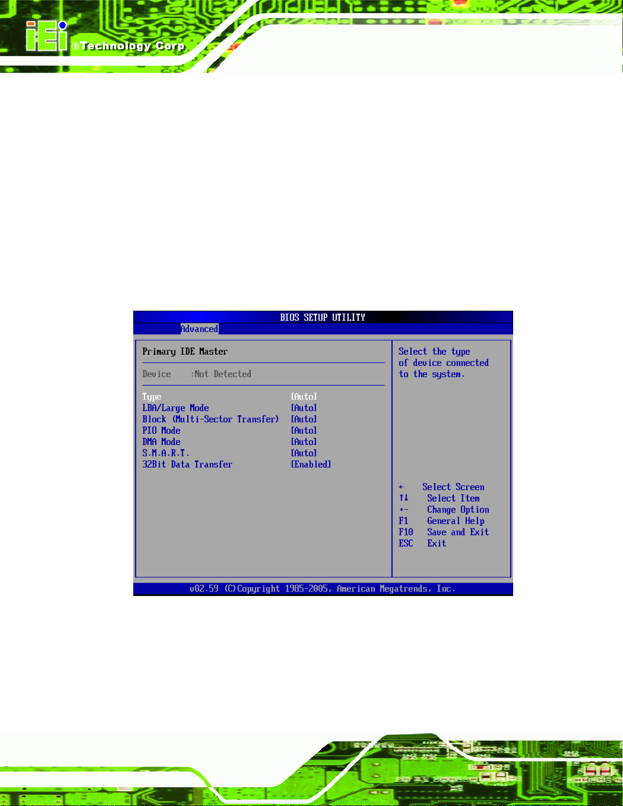
Secondary IDE Master
Secondary IDE Slave
IEM-9452 ETX Module
The IDE Configuration menu (
IDE devices installed in the system. If an IDE device is detected, and one of the above
listed four BIOS configuration options are selected, the IDE configuration options shown in
Section
6.3.2.1 appear.
BIOS Menu 4) allows changes to the configurations for the
6.3.2.1 IDE Master, IDE Slave
Use the IDE Master and IDE Slave configuration menu to view both primary and
secondary IDE device details and configure the IDE devices connected to the sy stem.
Page 60
BIOS Menu 5: IDE Master and IDE Slave Configuration
Page 77

IEM-9452 ETX Module
Auto-Detected Drive Parameters
The “grayed-out” items in the left frame are IDE disk drive parameters automatically
detected from the firmware of the selected IDE disk drive. The drive parameters are listed
as follows:
Device: Lists the device type (e.g. hard disk, CD-ROM etc.)
Type: Indicates the type of devices a user ca n manually select
LBA Mode: Indicates whether the LBA (Logical Block Addressing) is a
method of addressing data on a disk drive is supported or not.
Block Mode: Block mode boosts IDE drive performance by increa sing the
amount of data transferred. Only 512 bytes of data can be transferred per
interrupt if block mode is not used. Block mode allows transfers of up to 64 KB
per interrupt.
PIO Mode: Indicates the PIO mode of the installed device.
Async DMA: Indicates the highest Asynchronous DMA Mode that is
supported.
S.M.A.R.T.: Indicates whether or not the Self-Monitoring Analysis and
Reporting Technology protocol is supported.
32Bit Data Transfer: Enables 32-bit data transfer.
Type [Auto]
Use the Type BIOS option select the type of device the AMIBIOS attempts to boot from
after the Power-On Self-Test (POST) is complete.
Not Installed
Auto DEFAULT
BIOS is prevented from searching for an IDE disk
drive on the specified channel.
The BIOS auto detects the IDE disk drive type
attached to the specified channel. This setting should
be used if an IDE hard disk drive is attached to the
specified channel.
CD/DVD
The CD/DVD option specifies that an IDE CD-ROM
drive is attached to the specified IDE channel. The
Page 61
Page 78

BIOS does not attempt to search for other types of
IDE disk drives on the specified channel.
IEM-9452 ETX Module
ARMD
LBA/Large Mode [Auto]
Use the LBA/Large Mode option to disable or enable BIOS to auto detects LBA (Logical
Block Addressing). LBA is a method of addressing data on a disk drive. In LBA mode, the
maximum drive capacity is 137 GB.
Disabled
This option specifies an ATAPI Removable Media
Device. These include, but are not limited to:
ZIP
LS-120
BIOS is prevented from using the LBA mode control on
the specified channel.
Auto DEFAULT
Block (Multi Sector Transfer) [Auto]
Use the Block (Multi Sector Transfer) to disable or enable BIOS to auto detect if the
device supports multi-sector transfers.
Disabled
Auto DEFAULT
BIOS is prevented from using Multi-Sector Transfer on the
BIOS auto detects the LBA mode control on the specified
channel.
specified channel. The data to and from the device occurs
one sector at a time.
BIOS auto detects Multi-Sector Transfer support on the
drive on the specified channel. If supported the data
transfer to and from the device occurs multiple sectors at
Page 62
Page 79

IEM-9452 ETX Module
PIO Mode [Auto]
Use the PIO Mode option to select the IDE PIO (Programmable I/O) mode program timing
cycles between the IDE drive and the programmable IDE controller. As the PIO mode
increases, the cycle time decrease s.
a time.
Auto DEFAULT
0
1
2
3
4
DMA Mode [Auto]
PIO mode 0 selected with a maximum transfer rate of 3.3MBps
PIO mode 1 selected with a maximum transfer rate of 5.2MBps
PIO mode 2 selected with a maximum transfer rate of 8.3MBps
PIO mode 3 selected with a maximum transfer rate of 11.1MBps
PIO mode 4 selected with a maximum transfer rate of 16.6MBps
BIOS auto detects the PIO mode. Use this value if the IDE disk
drive support cannot be determined.
(This setting generally works with all hard disk drives
manufactured after 1999. For other disk drives, such as IDE
CD-ROM drives, check the specifications of the drive.)
Use the DMA Mode BIOS selection to adjust the DMA mode options.
Auto DEFAULT
SWDMA0
SWDMA1
Single Word DMA mode 0 selected with a maximum data
Single Word DMA mode 1 selected with a maximum data
BIOS auto detects the DMA mode. Use this value if the IDE
disk drive support cannot be determined.
transfer rate of 2.1MBps
transfer rate of 4.2MBps
Page 63
Page 80

IEM-9452 ETX Module
SWDMA2
MWDMA0
MWDMA1
MWDMA2
UDMA0
UDMA1
Single Word DMA mode 2 selected with a maximum data
transfer rate of 8.3MBps
Multi Word DMA mode 0 selected with a maximum data
transfer rate of 4.2MBps
Multi Word DMA mode 1 selected with a maximum data
transfer rate of 13.3MBps
Multi Word DMA mode 2 selected with a maximum data
transfer rate of 16.6MBps
Ultra DMA mode 0 selected with a maximum data transfer
rate of 16.6MBps
Ultra DMA mode 1 selected with a maximum data transfer
rate of 25MBps
UDMA2
UDMA3
UDMA4
UDMA5
Ultra DMA mode 2 selected with a maximum data transfer
rate of 33.3MBps
Ultra DMA mode 3 selected with a maximum data transfer
rate of 44MBps (To use this mode, it is required that an
80-conductor ATA cable is used.)
Ultra DMA mode 4 selected with a maximum data transfer
rate of 66.6MBps (To use this mode, it is required that an
80-conductor ATA cable is used.)
Ultra DMA mode 5 selected with a maximum data transfer
rate of 99.9MBps (To use this mode, it is required that an
80-conductor ATA cable is used.)
Page 64
Page 81

IEM-9452 ETX Module
S.M.A.R.T [Auto]
Use the S.M.A.R.T option to auto-detect, disable or enable Self-Monitoring Analysis and
Reporting Technology (SMART) on the drive on the specified channel. S.M.A.R.T predicts
impending drive failures. The S.M.A.R.T BIOS option enables or disabl es this function.
Auto DEFAULT
Disabled
Enabled
32Bit Data Transfer [Enabled]
Use the 32Bit Data Transfer BIOS option to enables or disable 32-bit data transfers.
Disabled
Enabled DEFAULT
Prevents BIOS from using the HDD SMART feature.
Allows BIOS to use the HDD SMART feature
Prevents the BIOS from using 32-bit data transfers.
BIOS auto detects HDD SMART support.
Allows BIOS to use 32-bit data transfers on supported
hard disk drives.
6.3.3 Floppy Configuration
Use the Floppy Configuration menu (BIOS Menu 6) to configure the floppy disk drive
connected to the system.
Page 65
Page 82

IEM-9452 ETX Module
BIOS Menu 6: Floppy Configuration
Floppy A/B [1.44 MB 31/2”]/[Disabled
Use the Floppy A/B option to configure the floppy disk drive. Options are listed below:
Disabled
360 KB 51/4”
1.2 MB 51/4”
720 KB 31/2”
1.44 MB 31/2’ DEFAULT
2.88 MB 31/2”
6.3.4 Super IO Configuration
Use the Super IO Configuration menu (BIOS Menu 7) to set or change the
configurations for the FDD controllers, parallel ports and serial ports.
Page 66
Page 83

IEM-9452 ETX Module
BIOS Menu 7: Super IO Configuration
OnBoard Floppy Controller [Enabled]
Use the OnBoard Floppy Controller to enable or disable the floppy controller. If a floppy
disk is not being used in the system, disabling this option frees up system resources that
can be redirected elsewhere in the system.
Disabled
Enabled
Serial Port1 Address [3F8/IRQ4]
Use the Serial Port1 Address option to select the Serial Port 1 base address.
Allows BIOS to disable the floppy controller
DEFAULT
Allows BIOS to enable the floppy controller
Disabled
3F8/IRQ4 DEFAULT
No base address is assigned to Serial Port 1
Serial Port 1 I/O port address is 3F8 and the interrupt
Page 67
Page 84

address is IRQ4
IEM-9452 ETX Module
3E8/IRQ4
2E8/IRQ3
Serial Port2 Address [2F8/IRQ3]
Use the Serial Port2 Address option to select the Serial Port 2 base address.
Disabled
2F8/IRQ3 DEFAULT
3E8/IRQ4
Serial Port 1 I/O port address is 3E8 and the interrupt
address is IRQ4
Serial Port 1 I/O port address is 2E8 and the interrupt
address is IRQ3
No base address is assigned to Serial Port 2
Serial Port 2 I/O port address is 3F8 and the interrupt
address is IRQ3
Serial Port 2 I/O port address is 3E8 and the interrupt
address is IRQ4
2E8/IRQ3
Serial Port2 Mode [Normal]
Use the Serial Port2 Mode option to select the Serial Port2 operational mode.
Normal DEFAULT
IrDA
ASK IR
Parallel Port Address [378]
Use the Parallel Port Address option to select the parallel port ba se address.
Disabled
Serial Port 2 I/O port address is 2E8 and the interrupt
address is IRQ3
Serial Port 2 mode is normal
Serial Port 2 mode is IrDA
Serial Port 2 mode is ASK IR
No base address is assigned to the Parallel Port
Page 68
Page 85

IEM-9452 ETX Module
378 DEFAULT
278
3BC
Parallel Port Mode [Normal]
Use the Parallel Port Mode option to select the mode the parallel port operates in.
Normal DEFAULT
EPP
Parallel Port I/O port address is 278
Parallel Port I/O port address is 3BC
Parallel Port I/O port address is 378
The normal parallel port mode is the standard mode
for parallel port operation.
The parallel port operates in the enhanced parallel
port mode (EPP). The EPP mode supports
bi-directional communication between the system
and the parallel port device and the transmission
rates between the two are much faster than the
Normal mode.
ECP
ECP+EPP
Parallel Port IRQ [IRQ7]
Use the Parallel Port IRQ option to set the parallel port interrupt address.
The parallel port operates in the extended
capabilities port (ECP) mode. The ECP mode
supports bi-directional communication between the
system and the parallel port device and the
transmission rates between the two are much faster
than the Normal mode
The parallel port is also be compatible with EPP and
ECP `devices described above
IRQ5
IRQ5 is assigned as the parallel port interrupt address
Page 69
Page 86

IEM-9452 ETX Module
IRQ7 DEFAULT
IRQ7 is assigned as the parallel port interrupt address
6.3.5 Hardware Health Configuration
The Hardware Health Configuration menu (BIOS Menu 8) shows the operating
temperature, fan speeds and system voltages.
Page 70
BIOS Menu 8: Hardware Health Configuration
The following system parameters and values are shown. The system parameters that are
monitored are:
System Temperatures: The following system temperatures are monitored
o System Temperature
o CPU Temperature
Voltages: The following system voltages are monitore d
o CPU
o Memory
o +3.30Vin
o +5.00Vin
Page 87

IEM-9452 ETX Module
o +5VSB
6.3.6 APM Configuration
The APM Configuration menu (BIOS Menu 9) allows the advanced power management
options to be configured.
BIOS Menu 9: Advanced Power Management Configuration
Power Button Mode [On/Off]
Use the Power Button Mode BIOS to specify how the power button functions.
On/Off D
Suspend
When the power button is pressed the system goes into
EFAULT
When the power button is pressed the system is either
turned on or off
suspend mode
Page 71
Page 88

Resume on Ring [Enabled]
Use the Resume on Ring BIOS option to enable activity on the RI (ring in) modem line to
rouse the system from a suspend or standby state. That is, the system will be roused by
an incoming call on a modem.
IEM-9452 ETX Module
Disabled
Enabled D
Resume on PME# [Disabled]
Use the Resume on PME# BIOS option to enable activity on the PCI PME (power
management event) controller to rouse the system from a suspend or standby state.
Disabled D
Enabled
Resume On RTC Alarm [Disabled]
Use the Resume On RTC Alarm option to specify the time the system should be roused
from a suspended state.
Wake event not generated by an incoming call
EFAULT
EFAULT
Wake event generated by PCI PME controller activity
Wake event generated by an incoming call
Wake event not generated by PCI PME controller
activity
Page 72
Disabled D
Enabled
EFAULT
If selected, the following appears with values that
The real time clock (RTC) cannot generate a wake
event
can be selected:
RTC Alarm Date (Days)
System Time
After setting the alarm, the computer turns itself on
from a suspend state when the alarm goes off.
Page 89

IEM-9452 ETX Module
Power Type Select [ATX]
Use the Power Type Select BIOS option to select the power supply that is connected to
the system.
AT
ATX D
Restore on AC Power Loss [Last State]
Use the Restore on AC Power Loss BIOS option to specify what state the system returns
to if there is a sudden loss of power to the system.
Power Off
Power On
Last State D
EFAULT
The system remains turned off
The system turns on
EFAULT
An AT power supply is connected to the system
An ATX power supply is connected to the system
The system returns to its previous state. If it was on, it
turns itself on. If it was off, it remains off.
6.3.7 Remote Access Configuration
Use the Remote Access Configuration menu (BIOS Menu 10) to configure remote
access parameters. The Remote Access Configuration is an AMIBIOS feature and
allows a remote host running a terminal program to display and configure the BIOS
settings.
Page 73
Page 90

IEM-9452 ETX Module
BIOS Menu 10: Remote Access Configuration [Advanced]
Remote Access [Disabled]
Use the Remote Access option to enable or disable access to the remote functionalities
of the system.
Disabled D
Enabled
EFAULT
Remote access configuration options shown below
Remote access is disabled.
appear:
Serial Port Number
Serial Port Mode
Flow Control
Page 74
Redirection after BIOS POST
Terminal Type
Page 91

IEM-9452 ETX Module
Serial Port Number [COM1]
Use the Serial Port Number option allows to select the serial port used for remote
access.
VT-UTF8 Combo Key Support
Sredir Memory Display Delay
These configuration options are discussed below.
COM1 D
COM2
EFAULT
System is remotely accessed through COM2
System is remotely accessed through COM1
NOTE: Make sure the selected COM port is enabled through the Super I/O configuration
menu.
Base Address, IRQ [3F8h, 4]
The Base Address, IRQ option cannot be configured and only shows the interrupt
address of the serial port listed above.
Serial Port Mode [115200 8,n,1]
Use the Serial Port Mode option to select baud rate through which the console redirection
is made. The following configuration options are available
115200 8,n,1 DEFAULT
57600 8,n,1
38400 8,n,1
19200 8,n,1
09600 8,n,1
NOTE:
Identical baud rate setting musts be set on the host (a management
computer running a terminal software) and the slave
Page 75
Page 92

Flow Control [None]
Use the Flow Control option to report the flow control method for the console redirection
application.
IEM-9452 ETX Module
None D
Hardware
Software
Redirection After BIOS POST [Always]
Use the Redirection After BIOS POST option to specify when console redirection should
occur.
Disabled
Boot Loader
Always D
EFAULT
Hardware is set as the console redirection
Software is set as the console redirection
The console is not redirected after POST
Redirection is active during POST and during Boot
EFAULT
No control flow,
Loader
Redirection is always active (Some OSes may not
work if set to Always)
Terminal Type [ANSI]
Use the Terminal Type BIOS option to specify the remote terminal type.
ANSI D
VT100
VT-UTF8
VT-UTF8 Combo Key Support [Enabled]
Use the VT-UFT8 Combo Key Support option to enable additional keys that are not
provided by VT100 for the PC 101 keyboard.
Page 76
EFAULT
The target terminal type is VT100
The target terminal type is VT-UTF8
The target terminal type is ANSI
Page 93

IEM-9452 ETX Module
The VT100 Terminal Definition is the standard convention used to configure and conduct
emergency management tasks with UNIX-based serv ers. VT100 does n ot support all keys
on the standard PC 101-key layout, however. The VT-UTF8 convention makes available
additional keys that are not provided by VT100 for the PC 101 keyboard.
Disabled
Enabled D
EFAULT
Disables the VT-UTF8 terminal keys
Enables the VT-UTF8 combination key. Support for
ANSI/VT100 terminals
Sredir Memory Display Delay [No Delay]
Use the Sredir Memory Display Delay option to select the delay before memory
information is displayed. Configuration options are listed below
No Delay DEFAULT
Delay 1 sec
Delay 2 sec
Delay 4 sec
6.3.8 USB Configuration
Use the USB Configuration menu (BIOS Menu 11) to read USB configuration
information and configure the USB settings.
Page 77
Page 94

IEM-9452 ETX Module
BIOS Menu 11: USB Configuration
USB Functions [4 USB Ports]
Use the USB Functions BIOS option to specify how many of the USB ports are USB 1.1
compatible.
Disabled
USB 2 Ports
USB 4 ports D
USB 2.0 Controller [Enabled]
Use the USB 2.0 Controller BIOS option to enable or disable the USB 2.0 controller
None of the ports are USB 1.1 compatible
Two ports are USB 1.1 compatible
EFAULT
Four ports are USB 1.1 compatible
Page 78
Disabled
Enabled DEFAULT
USB 2.0 controller disabled
USB 2.0 controller enabled
Page 95

IEM-9452 ETX Module
Legacy USB Support [Enabled]
The Legacy USB Support BIOS option refers to USB mouse and USB keyboard supp ort.
Normally if this option is not enabled, any attached USB mouse o r USB keyboard doe s not
become available until a USB compatible operating system is fully booted with all USB
drivers loaded. When this option is enabled, any attached USB mouse or USB keyboard
can control the system even when there is no USB driver loaded on the system.
Disabled
Enabled DEFAULT
USB2.0 Controller Mode [HiSpeed]
Use the USB2.0 Controller Mode option to set the speed of the USB2.0 controller.
FullSpeed
HiSpeed DEFAULT
Legacy USB support disabled
Legacy USB support enabled
The controller is capable of operating at 12Mb/s
The controller is capable of operating at 480Mb/s
6.3.8.1 USB Mass Storage Device Configuration
Use the USB Mass Storage Device Configur ation menu (BIOS Menu 12) to configure
USB mass storage class devices.
Page 79
Page 96

IEM-9452 ETX Module
BIOS Menu 12: USB Mass Storage Device Configuration
USB Mass Storage Reset Delay [20 Sec]
Use the USB Mass Storage Reset Delay option to set the number of seconds POST
waits for the USB mass storage device after the start unit command.
10 Sec
20 Sec D
30 Sec
40 Sec
POST waits 10 seconds for the USB mass storage
device after the start unit command.
EFAULT
POST waits 30 seconds for the USB mass storage
POST waits 40 seconds for the USB mass storage
POST waits 20 seconds for the USB mass storage
device after the start unit command.
device after the start unit command.
Page 80
device after the start unit command.
Page 97

IEM-9452 ETX Module
Device ##
The Device## field lists the USB devices that are connected to the system.
Emulation Type [Auto]
Use the Emulation T ype BIOS option to specify the type of emulation BIOS has to provide
for the USB device.
NOTE:
Please note that the device’s formatted type and the emulation type
provided by the BIOS must match for a device to boot properly. If both
types do not match then device’s behavior is undefined. To make sure both
types match, format the device using BIOS INT13h calls after selecting the
proper emulation option in BIOS setup. The FORMAT utility provided by
Microsoft® MS-DOS®, Microsoft® Windows® 95, and Microsoft®
Windows® 98 can be used for this purpose.
Auto D
Floppy
Forced FDD
Hard Disk
EFAULT
BIOS auto-detects the current USB.
The USB device will be emulated as a floppy drive.
The device can be either A: or B: responding to
INT13h calls that return DL = 0 or DL = 1
respectively.
Allows a hard disk image to be connected as a
floppy image. This option works only for drives
formatted with FAT12, FAT16 or FAT32.
Allows the USB device to be emulated as hard disk
responding to INT13h calls that return DL values of
80h or above.
Page 81
Page 98

IEM-9452 ETX Module
CDROM
6.4 PCI/PnP
Use the PCI/PnP menu (BIOS Menu 13) to configure advanced PCI and PnP settings.
WARNING:
Assumes the CD-ROM is formatted as bootable
media. All the devices that support block sizes
greater than 512 bytes can only be booted using this
option.
Setting wrong values for the BIOS selections in the PCIPnP BIOS
menu may cause the system to malfunction.
Page 82
BIOS Menu 13: PCI/PnP Configuration
Page 99

IEM-9452 ETX Module
IRQ# [Available]
Use the IRQ# address to specify what IRQs can be assigned to a particular peripheral
device.
Available DEFAULT
Reserved
Available IRQ addresses are:
IRQ3
IRQ4
IRQ5
IRQ7
IRQ9
IRQ10
IRQ 11
IRQ 14
IRQ 15
The specified IRQ is reserved for use by Legacy ISA
The specified IRQ is available to be used by
PCI/PnP devices
devices
DMA Channel# [Available]
Use the DMA Channel# option to assign a specific DMA channel to a particular PCI/PnP
device.
Available DEFAULT
Reserved
Available DMA Channels are:
DM Channel 0
The specified DMA is available to be used by
PCI/PnP devices
The specified DMA is reserved for use by Legacy
ISA devices
Page 83
Page 100

DM Channel 1
DM Channel 3
DM Channel 5
DM Channel 6
DM Channel 7
Reserved Memory Size [Disabled]
Use the Reserved Memory Size BIOS option to specify the amount of memory that
should be reserved for legacy ISA devices.
IEM-9452 ETX Module
6.5 Boot
Use the Boot menu (BIOS Menu 14) to configure system boot options.
Disabled DEFAULT
16K
32K
64K
16KB reserved for legacy ISA devices
32KB reserved for legacy ISA devices
54KB reserved for legacy ISA devices
No memory block reserved for legacy ISA devices
Page 84
 Loading...