

Page 1
®
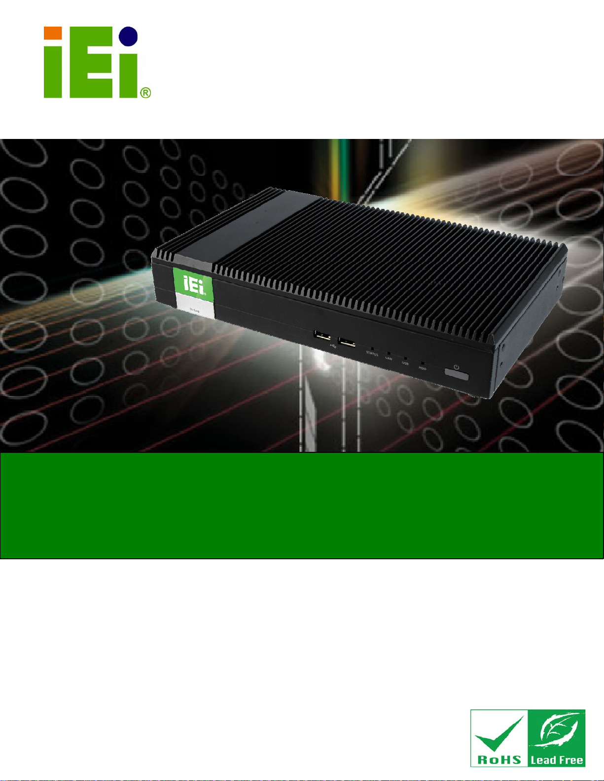
IDS-H61 Digital Signage Player
IDS-H61 Embedded System
IEI Technology Corp.
MODEL:
IDS-H61
Fanless Digital Signage Player with Intel
Dual-Core CPU, Intel® H61 Express Chipset, GbE LAN,
DisplayPort, DVI, RS-232, USB 2.0, SDHC Slot, RoHS Compliant
User Manual
Celeron® G530T
Rev. 1.00 – 7 February, 2013
Page I
Page 2
Date Version Changes
7 February, 2013 1.00 Initial release
IDS-H61 Digital Signage Player
Revision
Page II
Page 3

IDS-H61 Digital Signage Player
COPYRIGHT NOTICE
The information in this document is subject to change without prior notice in order to
improve reliability, design and function and does not represent a commitment on the part
of the manufacturer.
In no event will the manufacturer be liable for direct, indirect, special, incidental, or
consequential damages arising out of the use or inability to use the product or
documentation, even if advised of the possibility of such damages.
This document contains proprietary information protected by copyright. All rights are
Copyright
reserved. No part of this manual may be reproduced by any mechanical, electronic, or
other means in any form without prior written permission of the manufacturer.
TRADEMARKS
All registered trademarks and product names mentioned herein are used for identification
purposes only and may be trademarks and/or registered trademarks of their respective
owners.
Page III
Page 4

IDS-H61 Digital Signage Player
WARNING
This device complies with Part 15 of the FCC Rules. Operation is subject to the following
two conditions:
(1) this device may not cause harmful interference, and(2) this device must accept any
interference received, including interference that may cause u ndesired operation.
NOTE: This equipment has been tested and found to comply with the limits for a Class
B digital device, pursuant to part 15 of the FCC Rules. These limits are designed to
provide reasonable protection against harmful interference in a residential installation.
This equipment generates, uses and can radiate radio frequency energy and, if not
installed and used in accordance with the instructions, may cause harmful interference
to radio communications.
However, there is no guarantee that interference will not occur in a particular
installation. If this equipment does cause harmful interference to radio or television
reception, which can be determined by turning the equipment off and on, the user is
encouraged to try to correct the interference by one or more of the following measures:
—
Reorient or relocate the receiving antenna.
—
Increase the separation between the equipment and receiver.
—
Connect the equipment into an outlet on a circuit different from that to which the
receiver is connected.
—
Consult the dealer or an experienced radio/ TV technician for help.
You are cautioned that any change or modifications to the equipment not expressly
approve by the party responsible for compliance could void your authority to operate
such equipment.
IMPORTANT NOTE:
FCC Radiation Exposure Statement:
This equipment complies with FCC radiation exposure limits set forth for an uncontrolled
environment. This equipment should be installed and operated with minimum distance 20cm
between the radiator & your body.
Page IV
Page 5

IDS-H61 Digital Signage Player
Table of Contents
1 INTRODUCTION.......................................................................................................... 1
1.1 OVERVIEW.................................................................................................................. 2
1.2 FEATURE S................................................................................................................... 2
1.3 FRONT PANEL ............................................................................................................. 3
1.4 REAR PANEL............................................................................................................... 3
1.5 BOTTOM PANEL.......................................................................................................... 4
1.6 TECHNICAL SPECIFICATIONS ...................................................................................... 5
1.7 DIMENSIONS............................................................................................................... 7
2 UNPACKING................................................................................................................. 8
2.1 ANTI-STATIC PRECAUTIONS........................................................................................ 9
2.2 UNPACKING PRECAUTIONS......................................................................................... 9
2.3 UNPACKING CHECKLIST ........................................................................................... 10
3 INSTALLATION ..........................................................................................................11
3.1 INSTALLATION PRECAUTIONS ................................................................................... 12
3.1.1 High Surface Temperature ............................................................................... 12
3.2 SD CARD INSTALLATION .......................................................................................... 13
3.3 HDD INSTALLATION................................................................................................. 14
3.4 MOUNTING THE SYSTEM .......................................................................................... 16
3.5 EXTERNAL PERIPHERAL INTERFACE CONNECTION................................................... 18
3.5.1 Audio Line-out Connector................................................................................ 19
3.5.2 DisplayPort Connector.................................................................................... 19
3.5.3 LAN Connector ................................................................................................ 19
3.5.4 DVI-I Connector .............................................................................................. 20
3.5.5 Power Connector (12 V, Power Adapter) ........................................................ 21
3.5.6 RS-232 Serial Port Connector......................................................................... 21
3.5.7 USB 2.0 Connectors......................................................................................... 22
3.6 DRIVER INSTALLATION............................................................................................. 23
4 BIOS SCREENS........................................................................................................... 24
Page V
Page 6

4.1 INTRODUCTION......................................................................................................... 25
4.1.1 Starting Setup................................................................................................... 25
4.1.2 Using Setup...................................................................................................... 25
4.1.3 Getting Help..................................................................................................... 26
4.1.4 BIOS Menu Bar................................................................................................ 26
4.2 MAIN........................................................................................................................ 27
4.3 ADVANCED............................................................................................................... 28
4.3.1 CPU Configuration.......................................................................................... 29
4.3.2 USB Configuration........................................................................................... 31
4.3.3 H/W Monitor.................................................................................................... 32
4.4 CHIPSET ................................................................................................................... 33
4.5 BOOT........................................................................................................................ 35
4.6 SECURITY................................................................................................................. 37
4.7 EXIT......................................................................................................................... 38
IDS-H61 Digital Signage Player
5 MAINTENANCE......................................................................................................... 40
5.1 SYSTEM MAINTENANCE OVERVIEW ......................................................................... 41
5.2 COMPONENT REPLACEMENT PROCEDURE................................................................ 41
5.2.1 mSATA Replacement ........................................................................................ 42
5.2.2 SO-DIMM Replacement................................................................................... 43
6 INTERFACE CONNECTORS................................................................................... 45
6.1 PERIPHERAL INTERFACE CONNECTORS..................................................................... 46
6.2 INTERNAL PERIPHERAL CONNECTORS ...................................................................... 47
6.2.1 Fan Connector (FAN1)..................................................................................... 47
6.2.2 Fan Connector (FAN2)..................................................................................... 48
6.2.3 Half-Size PCIe Mini Slot (CN3)....................................................................... 48
6.2.4 Full-Size PCIe Mini Slot (CN5)....................................................................... 49
6.2.5 Full-Size PCIe Mini Slot for mSATA (JP2)...................................................... 50
6.2.6 RS-485 Connector (CN8)................................................................................. 51
6.2.7 SATA Connector (SATA2)................................................................................. 51
6.2.8 SATA Power Connector (SATA_PWR1)........................................................... 51
6.2.9 SPI Flash Connector (JSPI1)........................................................................... 52
A SAFETY PRECAUTIONS......................................................................................... 53
A.1 SAFETY PRECAUTIONS ............................................................................................ 54
Page VI
Page 7

IDS-H61 Digital Signage Player
A.1.1 General Safety Precautions............................................................................. 54
A.1.2 Anti-static Precautions.................................................................................... 55
A.1.3 Product Disposal............................................................................................. 56
A.2 MAINTENANCE AND CLEANING PRECAUTIONS........................................................ 56
A.2.1 Maintenance and Cleaning.............................................................................. 56
A.2.2 Cleaning Tools................................................................................................. 57
B BIOS MENU OPTIONS............................................................................................. 58
B.1 BIOS CONFIGURATION OPTIONS ............................................................................. 59
C WATCHDOG TIMER ................................................................................................ 60
Page VII
Page 8

IDS-H61 Digital Signage Player
List of Figures
Figure 1-1: IDS-H61 Series Pluggable Module PC.......................................................................2
Figure 1-2: Front Panel ..................................................................................................................3
Figure 1-3: Rear Panel....................................................................................................................4
Figure 1-4: Bottom Panel...............................................................................................................4
Figure 1-5: IDS-H61 Dimensions (mm).........................................................................................7
Figure 3-1: SDHC Slot Cover Retention Screw..........................................................................13
Figure 3-2: SDHC Card Installation.............................................................................................13
Figure 3-3: Top Cover Retention Screws...................................................................................14
Figure 3-4: HDD Bracket Retention Screws...............................................................................14
Figure 3-5: Inserting the HDD......................................................................................................15
Figure 3-6: SATA Cable Connection...........................................................................................15
Figure 3-7: Installing the HDD .....................................................................................................16
Figure 3-8: Installing the Mounting Bracket ..............................................................................17
Figure 3-9: Pace the System onto the Mounting Bracket.........................................................17
Figure 3-10: Mounting the System..............................................................................................18
Figure 3-11: RJ-45 Ethernet Connector......................................................................................20
Figure 3-12: DVI-I Connector.......................................................................................................21
Figure 3-13: Power Jack Connector ...........................................................................................21
Figure 3-14: Serial Port Pinouts..................................................................................................22
Figure 5-1: System Cover Retention Screws.............................................................................42
Figure 5-2: mSATA Module Location..........................................................................................42
Figure 5-3: mSATA Module Installation......................................................................................43
Figure 5-4: SO-DIMM Removal ....................................................................................................44
Figure 5-5: SO-DIMM Installation................................................................................................44
Figure 6-1: Main Board Layout Diagram (Front Side)...............................................................46
Page VIII
Page 9
IDS-H61 Digital Signage Player
List of Tables
Table 1-1: Technical Specifications..............................................................................................6
Table 2-1: Package List Contents...............................................................................................10
Table 3-1: LAN Pinouts ................................................................................................................19
Table 3-2: RJ-45 Ethernet Connector LEDs...............................................................................20
Table 3-3: DVI Connector Pinouts...............................................................................................21
Table 3-4: Serial Port Pinouts......................................................................................................22
Table 3-5: USB Port Pinouts........................................................................................................22
Table 4-1: BIOS Navigation Keys................................................................................................26
Table 6-1: Peripheral Interface Connectors...............................................................................47
Table 6-2: Fan Connector (FAN1) Pinouts .................................................................................47
Table 6-3: Fan Connector (FAN2) Pinouts .................................................................................48
Table 6-4: Half-Size PCIe Mini Card Slot (CN3) Pinouts ...........................................................49
Table 6-5: Full-Size PCIe Mini Card Slot (CN5) Pinouts............................................................50
Table 6-6: Full-Size PCIe Mini Card Slot (CN2) Pinouts............................................................51
Table 6-7: RS-485 Connector (CN8) Pinouts..............................................................................51
Table 6-8: SATA Connector (SATA2) Pinouts ...........................................................................51
Table 6-9: SATA Power Connector (SATA_PWR2) Pinouts.....................................................51
Table 6-10: SPI Flash Connector (JSPI1) Pinouts.....................................................................52
Page IX
Page 10

IDS-H61 Digital Signage Player
List of BIOS Menus
BIOS Menu 1: Main.......................................................................................................................27
BIOS Menu 2: Advanced..............................................................................................................28
BIOS Menu 3: CPU Configuration...............................................................................................29
BIOS Menu 4: USB Configuration...............................................................................................31
BIOS Menu 5: H/W Monitor..........................................................................................................32
BIOS Menu 6: Chipset..................................................................................................................33
BIOS Menu 7: Boot.......................................................................................................................35
BIOS Menu 8: Security.................................................................................................................37
BIOS Menu 9:Exit..........................................................................................................................38
Page X
Page 11
IDS-H61 Digital Signage Player
Chapter
1
1 Introduction
Page 1
Page 12
1.1 Overview
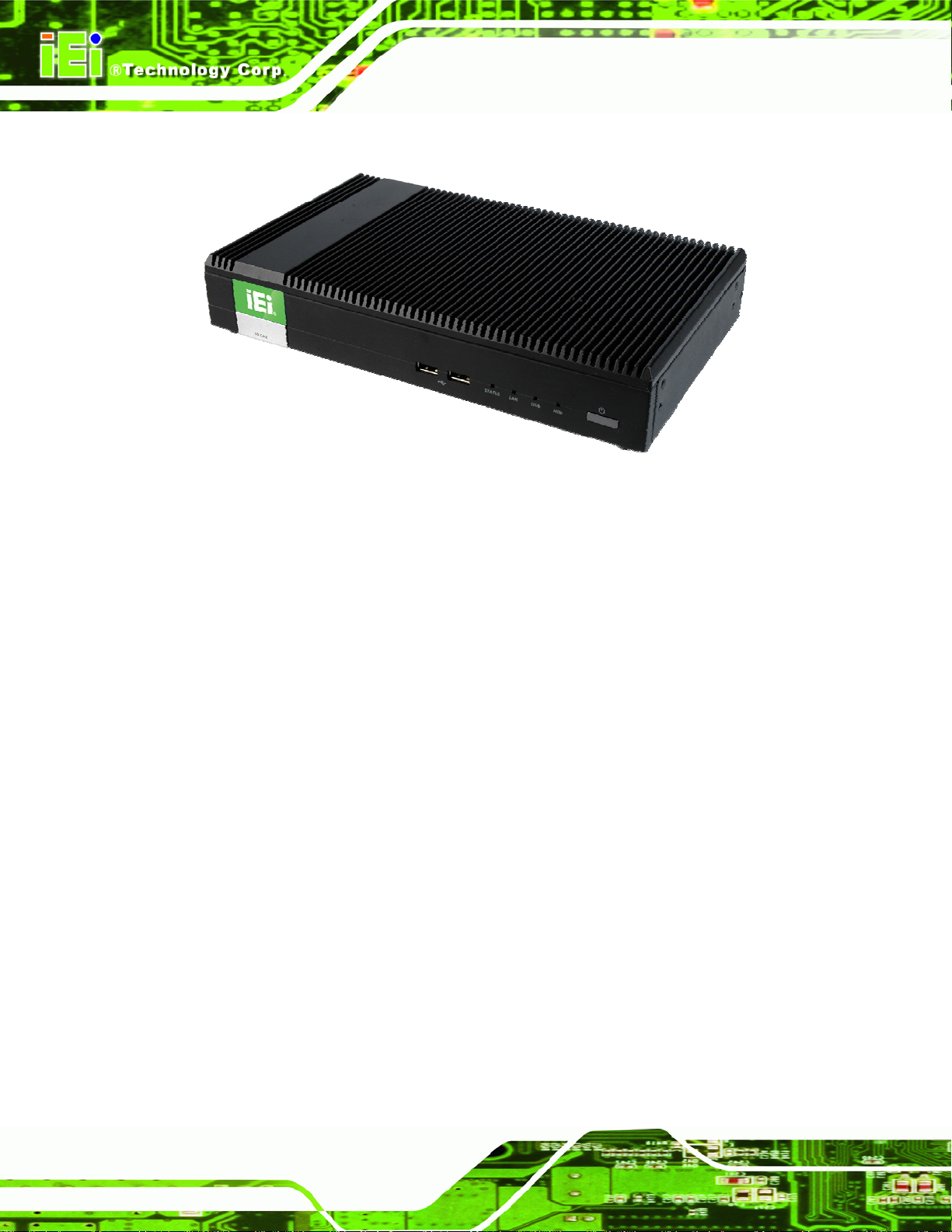
Figure 1-1: IDS-H61 Series Pluggable Module PC
The IDS-H61 series is a fanless digital signage player with Intel® Celeron® dual-core
IDS-H61 Digital Signage Player
G530T processor and Intel® H61 Express Chipset. The IDS-H61 is preinstalled 4 GB of
DDR3 SO-DIMM and can accommodate up to 16 GB of DDR3 memory. Storage in the
system is handled by the preinstalled 32 GB mSATA module, the 2.5” SATA HDD bay and
the SDHC card slot on the front panel.
The IDS-H61 includes a DisplayPort output interface supporting up to 2560 x 1600
resolutions and a DVI-I connector supporting up to 1920 x 1200 resolutions. Other slots
and connectors include half-size and full-size PCIe Mini card slots, RS-232, Gigabit
Ethernet, USB 2.0 ports and audio out.
1.2 Features
The IDS-H61 has the following features
Fanless design
LGA1155 2.0 GHz Intel® Celeron® G530T CPU supported
Intel® HD Graphics with full HD video decoding capability
One 32 GB mSATA module preinstalled
Page 2
One 2.5” SATA HDD bay
One SDHC card supported
One GbE LAN for high speed network applications
Page 13
IDS-H61 Digital Signage Player
One DisplayPort connector
One DVI-I connector
Four USB 2.0 ports
One RS-232 DB-9 serial port
One audio line-out jack
RoHS compliant design
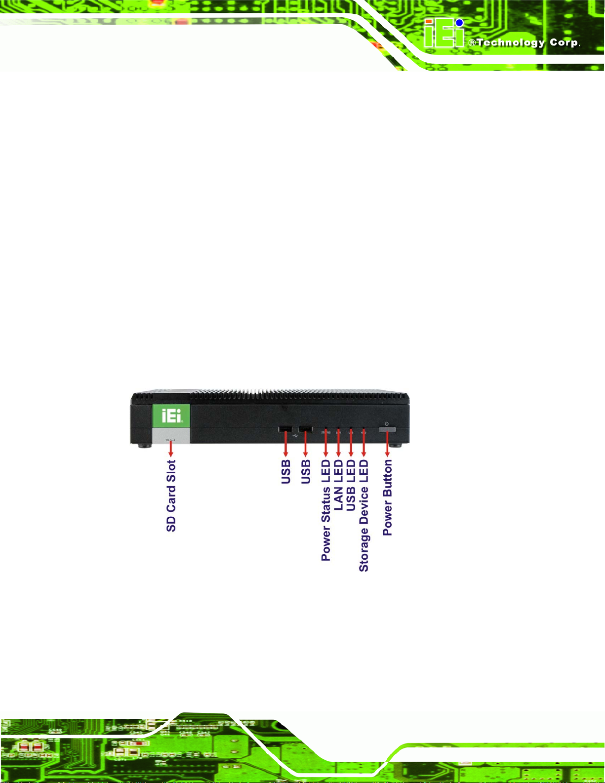
1.3 Front Panel
The front panel of the IDS-H61 contains one SDHC slot, two USB 2.0 ports, LED
indicators and a power button. The LED indicators are listed below. An overview of the
front panel is shown in
1 x Storage device (SD card/HDD) LED indicator
1 x USB LED indicator
1 x LAN LED indicator
1 x Status LED indicator (Blinking: booting; Solid: complete booting)
62Figure 1-2.
Figure 1-2: Front Panel
1.4 Rear Panel
The IDS-H61 rear panel provides access to the following external I/O connectors:
1 x 12 V DC input jack
Page 3
Page 14
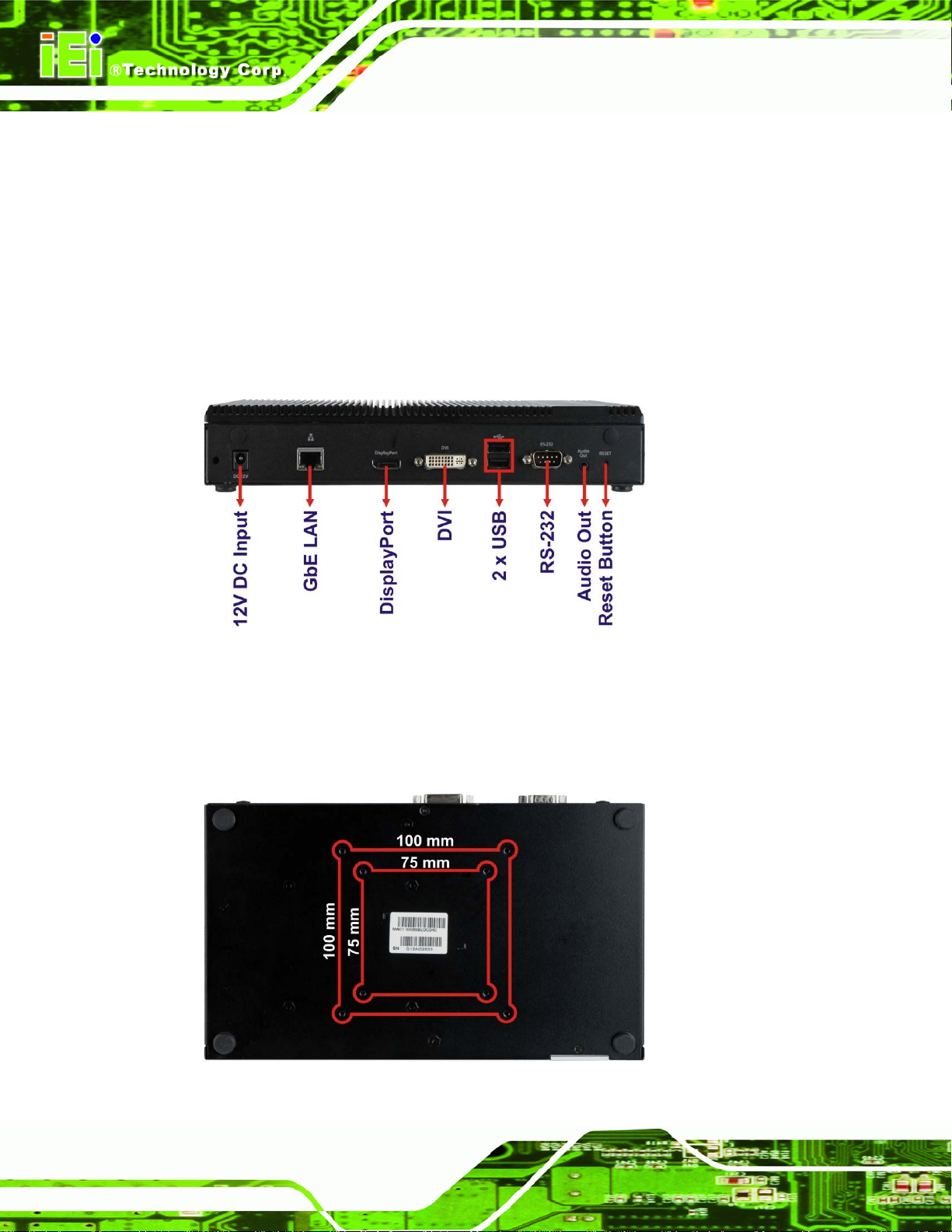
1 x Audio line-out jack
1 x DisplayPort connector
1 x GbE RJ-45 connector
1 x RS-232 DB-9 serial port
2 x USB 2.0 port connectors
1 x DVI-I connector
1 x Reset button
IDS-H61 Digital Signage Player
An overview of the rear panel is shown in
Figure 1-3: Rear Panel
1.5 Bottom Panel
The bottom panel of the IDS-H61 contains several screw holes for VESA mount.
62Figure 1-3 below.
Page 4
Figure 1-4: Bottom Panel
Page 15

IDS-H61 Digital Signage Player
1.6 Technical Specifications
The specifications for the IDS-H61 are listed below.
IDS-H61-C-4GB
CPU
System Chipset
System Memory
Graphics
Max. Output Resolution
Ethernet
Display
Serial Port
USB
2.0GHz Intel® Celeron® G530T dual-core CPU (2M cache)
Intel® H61 Express Chipset
Two 1333 MHz 2 GB DDR3 SDRAM SO-DIMM preinstalled
(system max. 16 GB)
Intel® HD Graphics
DVI-I: 1920 x 1200
DisplayPort: 2560 x 1600
One Intel® 82579LM GbE controller
One DVI-I connector
One DisplayPort 1.1 connector
One RS-232 DB-9 serial port
Four USB 2.0 ports
Audio
Storage
Expansion Slot
Wireless
Buttons
One audio out (5.1 channel Realtek ALC662 HD Audio codec)
One 32 GB mSATA module preinstalled
One 2.5” SATA HDD bay
One SDHC card slot on the front panel
Two PCIe Mini full-size slot
One PCIe Mini half-size slot (reserved for Wi-Fi module)
Optional 802.11b/g/n Wi-Fi
One power button
One reset button
s (one preinstalled with a 32 GB mSATA module)
Page 5
Page 16
IDS-H61 Digital Signage Player
Chassis Construction
Mounting
Power Input
Power Consumption
Operating Temperature
Storage Temperature
Color
Weight (Net/Gross)
Dimensions (W x D x H)
Operation Vibration
EMC
Aluminum Alloy (top cover) with heavy duty metal
VESA 75 mm or 100 mm
12V DC
41 W @ full loading
0ºC ~ 45ºC with air flow
-10 ºC ~ 55ºC
Black
2.1kg/4.5kg
267 mm x 160 mm x 45 mm
MIL-STD-810F 514.5C-1 with SATA HDD
MIL-STD-810F 514.5C-2 with mSATA
FCC, CE, LVD
Supported OS
Table 1-1: Technical Specifications
Microsoft Windows 7 or Microsoft Windows Embedded Standard 7
Page 6
Page 17
IDS-H61 Digital Signage Player
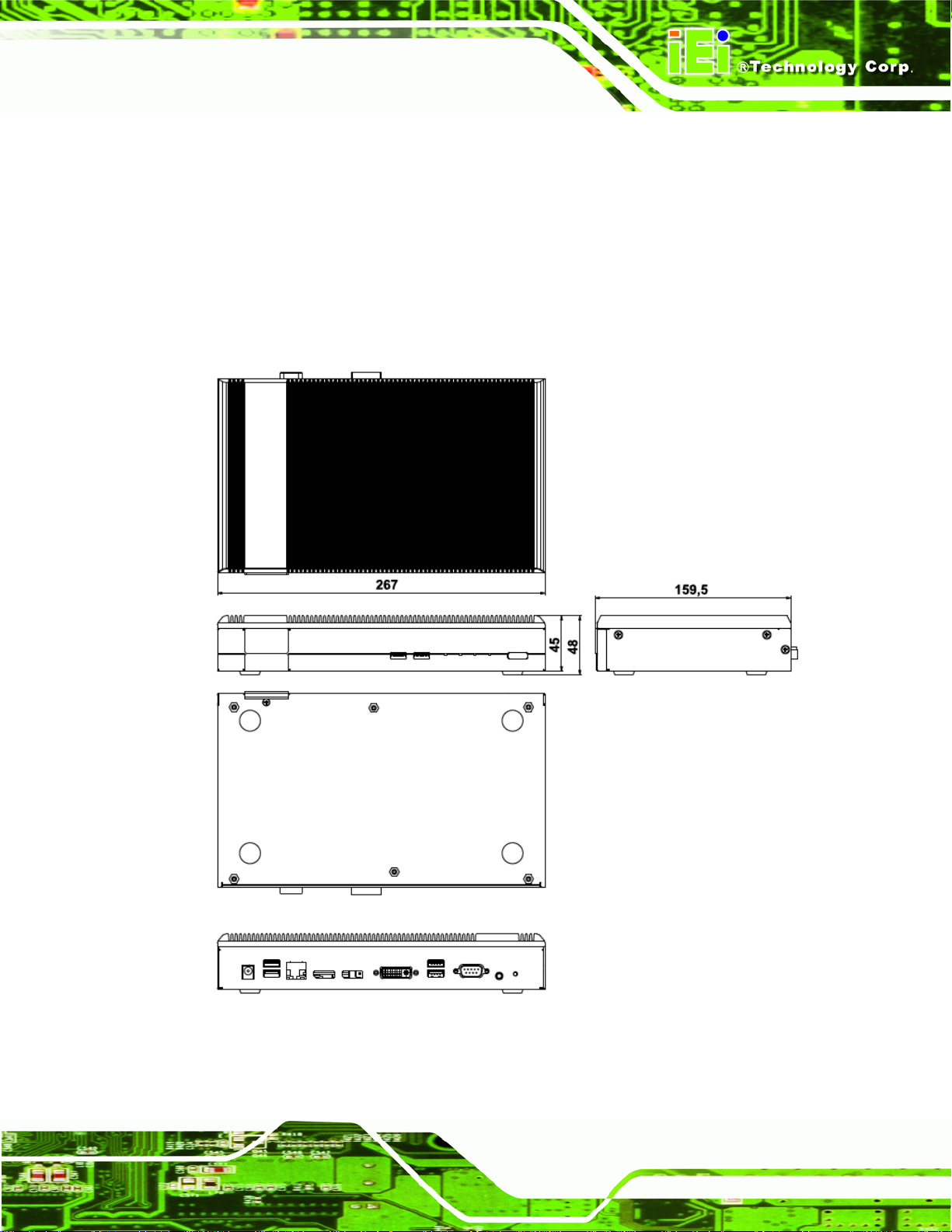
1.7 Dimensions
The physical dimensions of the IDS-H61 embedded systems are shown in 62Figure 1-5.
Height: 45.00 mm
Width: 267.00 mm
Length: 160.00 mm
Figure 1-5: IDS-H61 Dimensions (mm)
Page 7
Page 18

IDS-H61 Digital Signage Player
Chapter
2
2 Unpacking
Page 8
Page 19
IDS-H61 Digital Signage Player
2.1 Anti-static Precautions
WARNING:
Failure to take ESD precautions during installation may result in
permanent damage to the IDS-H61 and severe injury to the user.
Electrostatic discharge (ESD) can cause serious damage to electronic components,
including the IDS-H61. Dry climates are especially susceptible to ESD. It is therefore
critical that whenever the IDS-H61 or any other electrical component is handled, the
following anti-static precautions are strictly adhered to.
Wear an anti-static wristband: Wearing a simple anti-static wristband can
help to prevent ESD from damaging the board.
Self-grounding: Before handling the board, touch any grounded conducting
material. During the time the board is handled, frequently touch any
conducting materials that are connected to the ground.
Use an anti-static pad: When configuring the IDS-H61, place it on an
antic-static pad. This reduces the possibility of ESD damaging the IDS-H61.
2.2 Unpacking Precautions
When the IDS-H61 is unpacked, please do the following:
Follow the anti-static precautions outlined in Section
Make sure the packing box is facing upwards so the IDS-H61 does not fall out
of the box.
Make sure all the components shown in Section
2.1.
2.3 are present.
Page 9
Page 20
2.3 Unpacking Checklist
NOTE:
If some of the components listed in the checklist below are missing,
please do not proceed with the installation. Contact the IEI reseller or
vendor you purchased the IDS-H61 from or contact an IEI sales
representative directly. To contact an IEI sales representative, please
IDS-H61 Digital Signage Player
send an email to
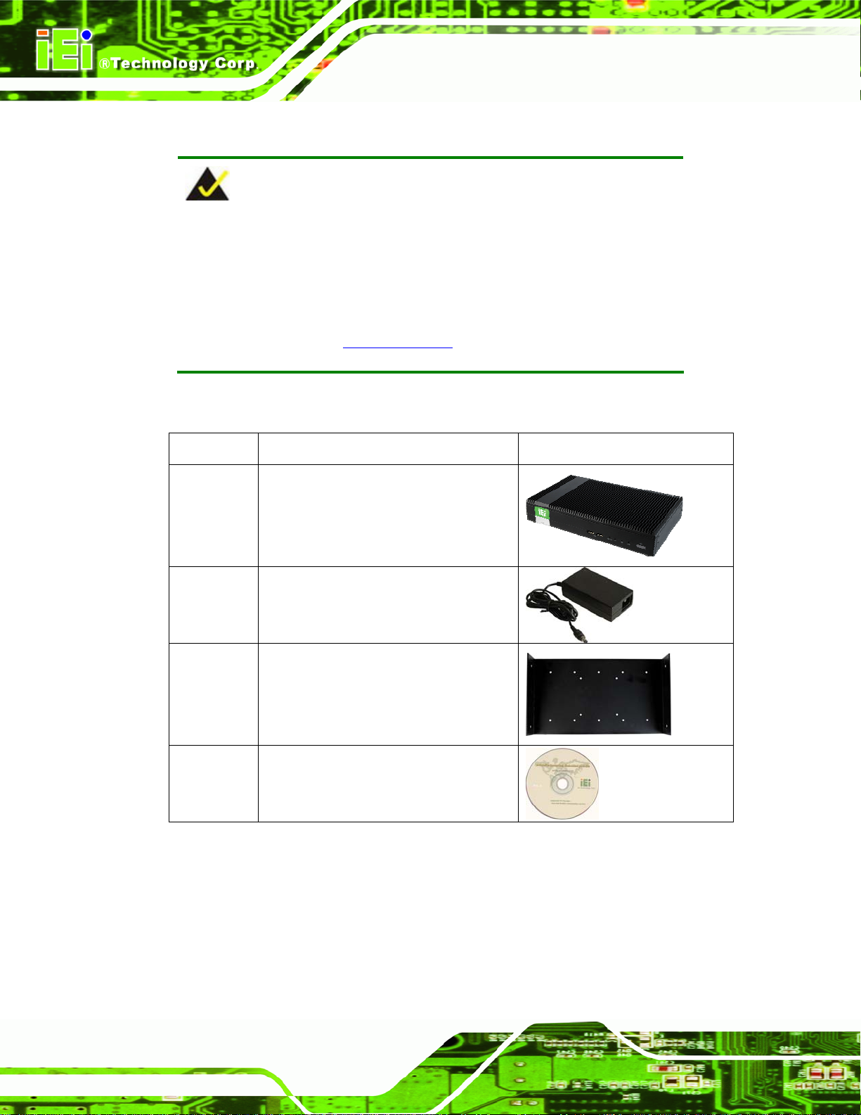
The IDS-H61 is shipped with the following components:
Quantity Item Image
1 IDS-H61 digital signage player
1 Power adapter
1 Wall mount kit
sales@iei.com.tw.
Page 10
1 Driver and manual CD
Table 2-1: Package List Contents
Page 21

IDS-H61 Digital Signage Player
Chapter
3
3 Installation
Page 11
Page 22
3.1 Installation Precautions
During installation, be aware of the precautions below:
Read the user manual: The user manual provides a complete description of
the IDS-H61, installation instructions and configuration options.
DANGER! Disconnect Power: Power to the IDS-H61 must be disconnected
during the installation process, or before any attempt is made to access the
rear panel. Electric shock and personal injury might occur if the rear panel of
the IDS-H61 is opened while the power cord is still connected to an electrical
outlet.
Qualified Personnel: The IDS-H61 must be installed and operated only by
trained and qualified personnel. Maintenance, upgrades, or repairs may only
be carried out by qualified personnel who are familiar with the associated
dangers.
IDS-H61 Digital Signage Player
Air Circulation: Make sure there is sufficient air circulation when installing the
IDS-H61. The IDS-H61’s cooling vents must not be obstructed by any objects.
Blocking the vents can cause overheating of the IDS-H61. Leave at least 5 cm
of clearance around the IDS-H61 to prevent overheating.
Grounding: The IDS-H61 should be properly grounded. The voltage feeds
must not be overloaded. Adjust the cabling and provide external overcharge
protection per the electrical values indicated on the label attached to the back
of the IDS-H61.
3.1.1 High Surface Temperature
WARNING:
Some surfaces of the equipment may become hot during operation.
The surface temperature may be up to several tens of degrees hotter
than the ambient temperature. Under these circumstances, the
Page 12
equipment needs to be protected against accidental contact.
The equipment is intended for installation in a RESTRICTED ACCESS LOCATION.
Page 23

IDS-H61 Digital Signage Player
Access can only be gained by SERVICE PERSONS or by USERS who have
been instructed about the reasons for the restrictions applied to the location
and about any precautions that shall be taken.
Access is through the use of a TOOL or lock and key, or other means of
security, and is controlled by the authority responsible for the location.
3.2 SD Card Installation
The IDS-H61 series has a SDHC card slot on the front panel. To install the SDHC card
into the system, please follow the steps below.
Step 1: Locate the SDHC card slot on the front panel. Remove the SDHC slot cover
retention screw on the bottom panel (
Figure 3-1).
Figure 3-1: SDHC Slot Cover Retention Screw
Step 2: Open the slot cover and insert a SDHC card into the slot. (
72Figure 3-2)
Figure 3-2: SDHC Card Installation
Page 13
Page 24

Step 3: Secure the SDHC card with the slot cover by fastening the previously removed
retention screw.
3.3 HDD Installation
The IDS-H61 has a 2.5” HDD bay inside the top cover. To install to an HDD, follow the
steps below.
Step 1: Remove the top cover by removing the four retention screws on both side panels
IDS-H61 Digital Signage Player
(two on each side). See
Figure 3-3: Top Cover Retention Screws
Step 2: Locate the HDD bracket inside the top cover. Remove the four HDD bracket
retention screws and lift the HDD bracket.
Figure 3-3.
Page 14
Figure 3-4: HDD Bracket Retention Screws
Page 25

IDS-H61 Digital Signage Player
Step 3: Insert an HDD into the bracket and secure the HDD to the bracket using four
retention screws (two screws on each side). See
Figure 3-5: Inserting the HDD
Step 4: Connect a SATA cable to the HDD. Secure the SATA cable with the HDD by
fastening two screws. See
Figure 3-6.
Figure 3-5.
Figure 3-6: SATA Cable Connection
Step 5: Install the HDD bracket in the same position it was before.
Page 15
Page 26

IDS-H61 Digital Signage Player
Figure 3-7: Installing the HDD
Step 6: Connect the SATA cable to the SATA connector and SATA power connector on
the motherboard.
Step 7: Reinstall the top cover.
3.4 Mounting the System
To mount the IDS-H61 onto a wall, please follow the steps below.
Step 1: Select the location on the wall for mounting the IDS-H61.
Step 2: Carefully mark the locations of the four mounting screw holes on the wall. Drill
four pilot holes at the marked locations on the wall for the bracket retention
screws.
Page 16
Step 3: Align the wall-mounting screw holes of the mounting bracket with the pilot holes.
Secure the mounting bracket to the wall by inserting the retention screws into
the four pilot holes and tightening them (
Figure 3-8).
Page 27
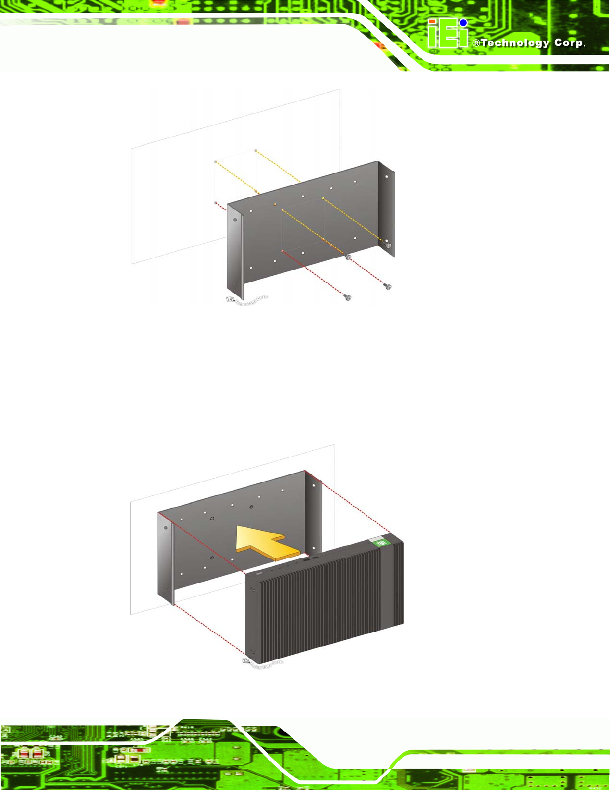
IDS-H61 Digital Signage Player
Figure 3-8: Installing the Mounting Bracket
Step 4: Place the IDS-H61 onto the mounting bracket and align the retention screw
holes on both sides of the system with the screw holes on the mounting bracket
Figure 3-9).
(
Figure 3-9: Pace the System onto the Mounting Bracket
Page 17
Page 28

Step 5: Secure the IDS-H61 to the mounting bracket with four M4 retention screws
Figure 3-10).
(
IDS-H61 Digital Signage Player
Figure 3-10: Mounting the System
NOTE:
The IDS-H61 can also be mounted on a VESA 75mm/100mm
complaint mounting device. Use the mounting bracket and follow the
instruction described above (Step 3 ~ Step 5) to mount the system
onto a VESA mount device.
3.5 External Peripheral Interface Connection
The following external peripheral devices can be connected to the external peripheral
interface connectors.
Audio devices
Page 18
RJ-45 Ethernet cable connectors
DisplayPort, DVI or VGA monitors
Serial port devices
Page 29

IDS-H61 Digital Signage Player
USB devices
To install these devices, connect the corresponding cable connector from the actual
device to the corresponding IDS-H61 external peripheral interface connector making sure
the pins are properly aligned.
3.5.1 Audio Line-out Connector
CN Label: Audio out
CN Type:
The audio line-out jack connects to a headphone or a speaker. With multi-channel
configurations, this port can also connect to front speakers.
Audio jack
3.5.2 DisplayPort Connector
CN Label: DisplayPort
CN Type:
The DisplayPort connector transmits a digital signal to compatible DisplayPort display
devices such as a TV or computer screen.
DisplayPort 1.1
3.5.3 LAN Connector
CN Label: LAN
CN Type:
RJ-45
Table 3-1
CN Pinouts:
The LAN connector allows connection to an external network.
Pin Description Pin Description
1 TRD1P0 5 TRD1P2
2 TRD1N0 6 TRD1N2
3 TRD1P1 7 TRD1P3
4 TRD1N1 8 TRD1N3
Table 3-1: LAN Pinouts
See
Page 19
Page 30

Figure 3-11: RJ-45 Ethernet Connector
The RJ-45 Ethernet connector has two status LEDs, one green and one yellow. The green
LED indicates activity on the port and the yellow LED indicates the port is linked. See
Table 3-2.
Activity/Link LED Speed LED
IDS-H61 Digital Signage Player
STATUS
Off No link Off 10 Mbps connection
Yellow Linked Green 100 Mbps connection
Blinking TX/RX activity Orange 1 Gbps connection
Table 3-2: RJ-45 Ethernet Connector LEDs
DESCRIPTION STATUS DESCRIPTION
3.5.4 DVI-I Connector
CN Label: DVI
CN Type:
CN Pinouts:
The 24-pin Digital Visual Interface (DVI) connector connects to high-speed,
high-resolution digital displays. The DVI-I connector supports both digital and analog
signals.
Pin Description
DVI-I connector
Table 3-3
See
Pin
Description
Pin
Description
Page 20
1
TMDS Data2-
2
TMDS Data2+
3
GND
4
N/C
5
N/C
6
DDC Clock [SCL]
7
DDC Data [SDA]
9
10
11
12
13
14
15
TMDS Data1TMDS Data1+
GND
NC
NC
PVDD1
GND
17
18
19
20
21
22
23
TMDS Data0TMDS Data0+
GND
NC
NC
GND
TMDS Clock +
Page 31
IDS-H61 Digital Signage Player
Pin Description
8
Analog vertical sync
C1 Analog Red
C2 Analog Green
C3 Analog Blue
C4 Analog Horizontal Sync -C5 Analog GND
Table 3-3: DVI Connector Pinouts
Pin
16
--
--
--
--
Description
GND
--
--
--
--
--
Figure 3-12: DVI-I Connector
3.5.5 Power Connector (12 V, Power Adapter)
Pin
24
--
--
--
--
--
Description
TMDS Clock -
--
--
--
--
--
CN Label: DC 12V
CN Type:
The connector supports the 12V power adapter.
DC jack
Figure 3-13: Power Jack Connector
3.5.6 RS-232 Serial Port Connector
CN Label: RS-232
CN Type:
CN Pinouts:
Male DB-9
Table 3-4
See
The RS-232 serial port connector allows connection to a serial device.
Page 21
Page 32

Pin Description Pin Description
1 DCD 6 CTS
2 DSR 7 DT
3 SIN 8 RI
4 RTS 9 GND
5 SOUT 10 GND
IDS-H61 Digital Signage Player
Table 3-4: Serial Port Pinouts
Figure 3-14: Serial Port Pinouts
3.5.7 USB 2.0 Connectors
CN Label: USB
CN Type:
CN Pinouts:
The USB ports are for connecting USB peripheral devices to the system.
Pin Description Pin Description
1 VCC 5 VCC
2 DATA- 6 DATA3 DATA+ 7 DATA+
4 GROUND 8 GROUND
Table 3-5: USB Port Pinouts
USB 2.0 port
See
Table 3-5
Page 22
Page 33

IDS-H61 Digital Signage Player
3.6 Driver Installation
NOTE:
The content of the CD may vary throughout the life cycle of the product
and is subject to change without prior notice. Visit the IEI website or
contact technical support for the latest updates.
The following drivers can be installed on the system:
Intel AHCI
Intel chipset
Intel Ethernet
Intel® HD Graphics
Intel® MEI
Realtek HD Audio
Double click the setup file in each driver folder and follow the step-by-step instruction of
the installation wizard to install the drivers listed above.
Page 23
Page 34
IDS-H61 Digital Signage Player
Chapter
4
4 BIOS Screens
Page 24
Page 35

IDS-H61 Digital Signage Player
4.1 Introduction
The BIOS is programmed onto the BIOS chip. The BIOS setup program allows changes to
certain system settings. This chapter outlines the options that can be changed.
4.1.1 Starting Setup
The UEFI BIOS is activated when the computer is turned on. The setup program can be
activated in one of two ways.
1. Press the DEL or F2 key as soon as the system is turned on or
2. Press the DEL or F2 key when the “Press DEL or F2 to enter SETUP”
message appears on the screen. 0.
If the message disappears before the DEL or F2 key is pressed, restart the computer and
try again.
4.1.2 Using Setup
Use the arrow keys to highlight items, press ENTER to select, use the PageUp and
PageDown keys to change entries, press F1 for help and press E
keys are shown in.
Key Function
Up arrow Move to previous item
Down arrow Move to next item
Left arrow Move to the item on the left hand side
Right arrow Move to the item on the right hand side
+ Increase the numeric value or make changes
- Decrease the numeric value or make changes
Page Up key Increase the numeric value or make changes
Page Dn key Decrease the numeric value or make changes
SC to quit. Navigation
Page 25
Page 36

Key Function
Esc key Main Menu – Quit and not save changes into CMOS
F1 General help, only for Status Page Setup Menu and Option
F2 Previous values
F3 Load optimized defaults
F4 Save changes and Exit BIOS
Table 4-1: BIOS Navigation Keys
4.1.3 Getting Help
IDS-H61 Digital Signage Player
Status Page Setup Menu and Option Page Setup Menu --
Exit current page and return to Main Menu
Page Setup Menu
When F1 is pressed a small help window describing the appropriate keys to use and the
possible selections for the highlighted item appears. To exit the Help Window press E
the F1 key again.
4.1.4 BIOS Menu Bar
The menu bar on top of the BIOS screen has the following main items:
Main – Changes the basic system configuration.
Advanced – Changes the advanced system settings.
Chipset – Changes the chipset settings.
Boot – Changes the system boot configuration.
Security – Sets User and Supervisor Passwords.
Save & Exit – Selects exit options and loads default settings
The following sections completely describe the configuration options found in the menu
SC or
Page 26
items at the top of the BIOS screen and listed above.
Page 37

IDS-H61 Digital Signage Player
4.2 Main
The Main BIOS menu (BIOS Menu 1) appears when the BIOS Setup program is entered.
The Main menu gives an overview of the basic system information.
Aptio Setup Utility – Copyright (C) 2012 American Megatrends, Inc.
Main Advanced Chipset Boot Security Save & Exit
BIOS Information
BIOS Vendor American Megatrends
Core Version 4.6.5.3
Compliency UEFI 2.3; PI 1.2
Project Version QC24AR06 x64
Build Date 09/06/2012 11:48:35
Memory Information
Total Memory 4096 MB (DDR3)
Memory Frequency 1067 Mhz
System Date [Tue 11/27/2011]
System Time [15:10:27]
Access Level Administrator
Version 2.15.1226. Copyright (C) 2012 American Megatrends, Inc.
Set the Date. Use Tab to
switch between Data
elements.
----------------------
ÅÆ
↑ ↓: Select Item
Enter Select
+ - Change Opt.
F1 General Help
F2 Previous Values
F3 Optimized Defaults
F4 Save & Exit
ESC Exit
: Select Screen
BIOS Menu 1: Main
Î System Overview
The BIOS Information lists a brief summary of the BIOS. The fields in BIOS Information
cannot be changed. The items shown in the system overview include:
BIOS Vendor: Installed BIOS vendor
Core Version: Current BIOS version
Compliency: Current compliant version
Project Version: the board version
Build Date: Date the current BIOS version was made
Î Memory Information
The Memory Information lists a brief summary of the on-board memory. The fields in
Memory Information cannot be changed.
Total Memory: Displays the auto-detected system memory size and type.
Page 27
Page 38

The System Overview field also has two user configurable fields:
Î System Date [xx/xx/xx]
Use the System Date option to set the system date. Manually enter the day, month and
year.
Î System Time [xx:xx:xx]
Use the System Time option to set the system time. Manually enter the hours, minutes
and seconds.
4.3 Advanced
Use the Advanced menu (BIOS Menu 2) to configure the CPU and peripheral devices
through the following sub-menus:
IDS-H61 Digital Signage Player
WARNING!
Setting the wrong values in the sections below may cause the system
to malfunction. Make sure that the settings made are compatible with
the hardware.
Aptio Setup Utility – Copyright (C) 2012 American Megatrends, Inc.
Main Advanced Chipset Boot Security Save & Exit
> CPU Configuration
> USB Configuration
> H/M Monitor
Version 2.15.1226. Copyright (C) 2012 American Megatrends, Inc.
CPU Configuration
Parameters
----------------------
ÅÆ
↑ ↓: Select Item
Enter Select
+ - Change Opt.
F1 General Help
F2 Previous Values
F3 Optimized Defaults
F4 Save & Exit
ESC Exit
: Select Screen
Page 28
BIOS Menu 2: Advanced
Page 39
W
IDS-H61 Digital Signage Player
4.3.1 CPU Configuration
Use the CPU Configuration menu (BIOS Menu 3) to view detailed CPU specifications
and configure the CPU.
Aptio Setup Utility – Copyright (C) 2012 American Megatrends, Inc.
Advanced
CPU Configuration
Intel(R) Celeron(R) CPU G530T @ 2.00GHz
CPU Signature 206a7
Microcode Patch 26
Max CPU Speed 2000 MHz
Min CPU Speed 1600 MHz
CPU Speed 2000 MHz
Processor Cores 2
Intel HT Technology Not Supported
Intel VT-x Technology Supported
Intel SMX Technology Not Supported
64-bit Supported
L1 Data Cache 32 kB x 2
L1 Code Cache 32 kB x 2
L2 Cache 256 kB x 2
L3 Cache 2048 kB
Intel Virtualization Technology [Disabled]
Version 2.15.1226. Copyright (C) 2012 American Megatrends, Inc.
hen enabled, a VMM can
utilize the additional
hardware capabilities
provided by Vanderpool
Technology
----------------------
ÅÆ
: Select Screen
↑ ↓: Select Item
Enter Select
+ - Change Opt.
F1 General Help
F2 Previous Values
F3 Optimized Defaults
F4 Save & Exit
ESC Exit
BIOS Menu 3: CPU Configuration
The CPU Configuration menu (
Processor Type: Lists the brand name of the CPU being used
CPU Signature: Lists the CPU signature value.
Microcode Patch: Lists the microcode patch being used.
Max CPU Speed: Lists the maximum CPU processing speed.
Min CPU Speed: Lists the minimum CPU processing speed.
CPU Speed: Lists the CPU processing speed.
Processor Cores: Lists the number of the processor core
Intel HT Technology: Indicates if Intel HT Technology is supported by the
CPU.
Intel VT-x Technology: Indicates if Intel VT-x Technology is supported by the
CPU.
BIOS Menu 3) lists the following CPU details:
Page 29
Page 40

Intel SMX Technology: Indicates if Intel SMX Technology is supported by the
CPU.
L1 Data Cache: Lists the amount of data storage space on the L1 cache.
L1 Code Cache: Lists the amount of code storage space on the L1 cache.
L2 Cache: Lists the amount of storage space on the L2 cache.
L3 Cache: Lists the amount of storage space on the L3 cache.
Î Intel Virtualization Technology [Disabled]
Use the Intel Virtualization Technology option to enable or disable virtualization on the
system. When combined with third party software, Intel® Virtualization technology allows
several OSs to run on the same system at the same time.
IDS-H61 Digital Signage Player
Î
Disabled DEFAULT
Î
Enabled
Disables Intel Virtualization
Technology.
Enables Intel Virtualization Technology.
Page 30
Page 41
d
IDS-H61 Digital Signage Player
4.3.2 USB Configuration
Use the USB Configuration menu (BIOS Menu 4) to read USB configuration information
and configure the USB settings.
Aptio Setup Utility – Copyright (C) 2012 American Megatrends, Inc.
Advanced
USB Configuration
USB Devices:
1 Keyboard, 2 Hubs
Legacy USB Support [Enabled]
Version 2.15.1226. Copyright (C) 2012 American Megatrends, Inc.
Enables Legacy USB
support. AUTO option
isables legacy support
if no USB devices are
connected. DISABLE
option will keep USB
devices available only
for EFI applications.
---------------------
ÅÆ
: Select Screen
↑ ↓: Select Item
Enter Select
+ - Change Opt.
F1 General Help
F2 Previous Values
F3 Optimized Defaults
F4 Save & Exit
ESC Exit
BIOS Menu 4: USB Configuration
Î USB Devices
The USB Devices Enabled field lists the USB devices that are enabled on the system
Î Legacy USB Support [Enabled]
Use the Legacy USB Support BIOS option to enable USB mouse and USB keyboard
support. Normally if this option is not enabled, any attached USB mouse or USB keyboard
does not become available until a USB compatible operating system is fully booted with all
USB drivers loaded. When this option is enabled, any attached USB mouse or USB
keyboard can control the system even when there is no USB driver loaded onto the
system.
Î
Enabled DEFAULT
Legacy USB support enabled
Page 31
Page 42

IDS-H61 Digital Signage Player
Î
Disabled
Î
Auto
Legacy USB support disabled
Legacy USB support disabled if no USB devices are
connected
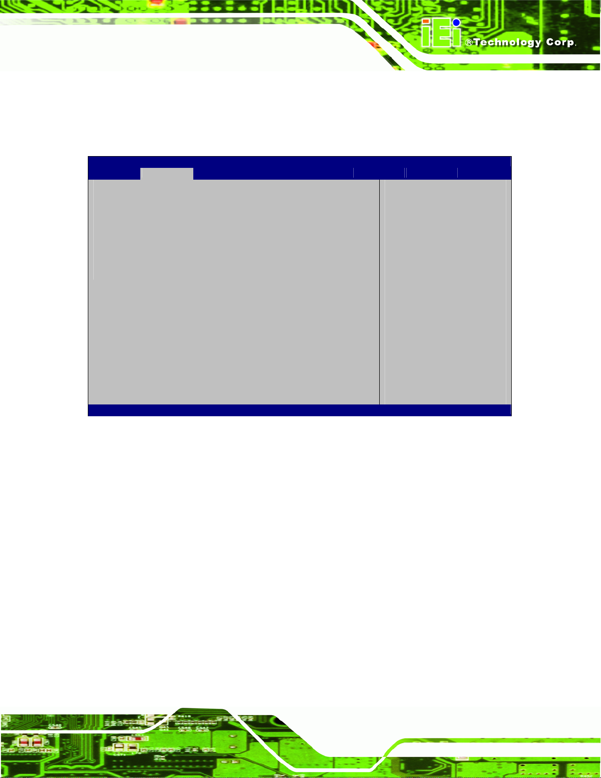
4.3.3 H/W Monitor
The H/W Monitor menu (BIOS Menu 5) contains the fan configuration submenus and
displays operating temperature, fan speeds and system voltages.
Aptio Setup Utility – Copyright (C) 2012 American Megatrends, Inc.
Advanced
PC Health Status
Smart Fan Function [Enable]
CPU Temperature :+30 C
CPU FAN Speed :N/A
V_CORE : +1.072 V
V_3.3 : +3.392 V
+1.05V : +1.064 V
Vcc1_5VDDR : +1.600 V
5VSB : +4.944 V
VCC3V : +3.376 V
VSB3 : +3.408 V
VBAT : +2.992 V
Version 2.15.1226. Copyright (C) 2012 American Megatrends, Inc.
Smart Fan Mode Select
---------------------
ÅÆ
: Select Screen
↑ ↓: Select Item
Enter Select
+ - Change Opt.
F1 General Help
F2 Previous Values
F3 Optimized Defaults
F4 Save & Exit
ESC Exit
BIOS Menu 5: H/W Monitor
Î Smart Fan Function [Enable]
Use the Smart Fan Function option to disable or enable the Smart Fan.
Î
Disable
Î
Enable DEFAULT
Î H/W Monitor
The following system parameters and values are shown. The system parameters that are
monitored are:
Page 32
The smart fan is disabled.
The smart fan is enabled.
Page 43

IDS-H61 Digital Signage Player
CPU Temperature
CPU Fan Speed
Voltages:
o V_CORE
o V_3.3
o +1.05V
o Vcc1_5VDDR
o 5VSB
o VCC3V
o VSB3
o VBAT
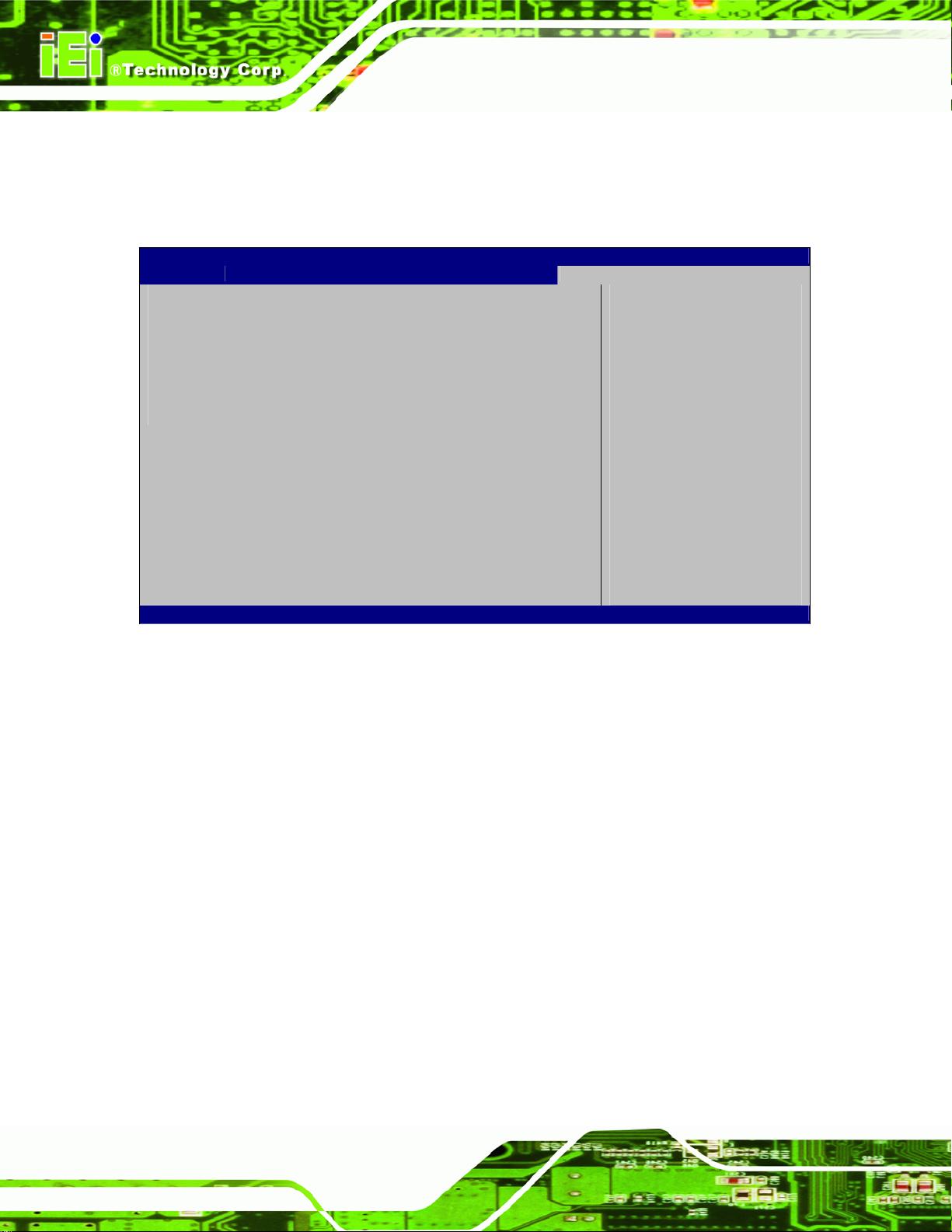
4.4 Chipset
Use the Chipset menu (BIOS Menu 6) to configure the system chipset.
Aptio Setup Utility – Copyright (C) 2012 American Megatrends, Inc.
Main Advanced Chipset Boot Security Save & Exit
DVMT Pre-Allocated [64M]
DVMT Total Gfx Mem [256M]
SATA Mode Selection [AHCI]
Restore AC Power Loss [Last State]
Version 2.15.1226. Copyright (C) 2012 American Megatrends, Inc.
BIOS Menu 6: Chipset
Î DVMT Pre-Allocated [64M]
Use the DVMT Pre-Allocated option to set the amount of system memory allocated to the
IGD Share Memory Size
---------------------
ÅÆ
↑ ↓: Select Item
Enter Select
+ - Change Opt.
F1 General Help
F2 Previous Values
F3 Optimized Defaults
F4 Save & Exit
ESC Exit
: Select Screen
integrated graphics processor when the system boots. The system memory allocated can
then only be used as graphics memory, and is no longer available to applications or the
operating system. Configuration options are listed below:
Page 33
Page 44

32M
64M Default
128M
160M
192M
224M
256M
288M
320M
352M
384M
416M
448M
480M
IDS-H61 Digital Signage Player
512M
1024M
Î DVMT Total Gfx Mem [256M]
Use the DVMT Total Gfx Mem option to select DVMT5.0 total graphic memory size used
by the internal graphic device. The following options are available:
128M
256M
MAX
Î SATA Mode Selection [IDE Mode]
Use the SATA Mode Selection option to configure SATA devices as normal IDE devices.
Î
IDE
Î
AHCI DEFAULT
DEFAULT
Configures SATA devices as normal IDE device.
Configures SATA devices as AHCI device.
Page 34
Î
RAID
Configures SATA devices as RAID device.
Page 45

IDS-H61 Digital Signage Player
Î Restore on AC Power Loss [Last State]
Use the Restore on AC Power Loss BIOS option to specify what state the system
returns to if there is a sudden loss of power to the system.
Î
Power Off
Î
Power On
Î
Last State DEFAULT
The system remains turned off
The system turns on
The system returns to its previous state. If it was on, it
turns itself on. If it was off, it remains off.
4.5 Boot
Use the Boot menu (BIOS Menu 7) to configure system boot options.
Aptio Setup Utility – Copyright (C) 2012 American Megatrends, Inc.
Main Advanced Chipset Boot Security Save & Exit
Boot Configuration
Bootup NumLock State [On]
Quiet Boot [Disabled]
Boot Option Priorities
Boot Option #1 [P1: EverGreen mSATA…]
Boot Option #2 [Disabled]
Version 2.15.1226. Copyright (C) 2012 American Megatrends, Inc.
Select the keyboard
NumLock state
---------------------
ÅÆ
↑ ↓: Select Item
Enter Select
+ - Change Opt.
F1 General Help
F2 Previous Values
F3 Optimized Defaults
F4 Save & Exit
ESC Exit
: Select Screen
BIOS Menu 7: Boot
Î Bootup NumLock State [On]
Use the Bootup NumLock State BIOS option to specify if the number lock setting must
be modified during boot up.
Page 35
Page 46

IDS-H61 Digital Signage Player
Î
On DEFAULT
Î
Off
Î Quiet Boot [Disabled]
Use the Quiet Boot BIOS option to select the screen display when the system boots.
Allows the Number Lock on the keyboard to be
enabled automatically when the computer system
boots up. This allows the immediate use of the
10-key numeric keypad located on the right side of
the keyboard. To confirm this, the Number Lock LED
light on the keyboard is lit.
Does not enable the keyboard Number Lock
automatically. To use the 10-keys on the keyboard,
press the Number Lock key located on the upper
left-hand corner of the 10-key pad. The Number
Lock LED on the keyboard lights up when the
Number Lock is engaged.
Î
Disabled DEFAULT
Î
Enabled
Normal POST messages displayed
OEM Logo displayed instead of POST messages
Page 36
Page 47

S
IDS-H61 Digital Signage Player
4.6 Security
Use the Security menu (BIOS Menu 8) to set system and user passwords.
Aptio Setup Utility – Copyright (C) 2012 American Megatrends, Inc.
Main Advanced Chipset Boot Security Save & Exit
Password Description
If ONLY the Administrator’s password is set,
then this only limits access to Setup and is
only asked for when entering Setup.
If ONLY the User’s password is set, then this
is a power on password and must be entered to
boot or enter Setup. In Setup the User will
have Administrator rights.
The password must be 3 to 20 characters long.
Administrator Password
User Password
Version 2.15.1226. Copyright (C) 2012 American Megatrends, Inc.
et Setup Administrator
Password
---------------------
ÅÆ
↑ ↓: Select Item
Enter Select
+ - Change Opt.
F1 General Help
F2 Previous Values
F3 Optimized Defaults
F4 Save & Exit
ESC Exit
: Select Screen
BIOS Menu 8: Security
Î Administrator Password
Use the Administrator Password to set or change a administrator password.
Î User Password
Use the User Password to set or change a user password.
Page 37
Page 48
IDS-H61 Digital Signage Player
4.7 Exit
Use the Exit menu (BIOS Menu 9) to load default BIOS values, optimal failsafe values
and to save configuration changes.
Aptio Setup Utility – Copyright (C) 2012 American Megatrends, Inc.
Main Advanced Chipset Boot Security Save & Exit
Save Changes and Reset
Discard Changes and Reset
Restore Defaults
Save as User Defaults
Restore User Defaults
Version 2.15.1226. Copyright (C) 2012 American Megatrends, Inc.
Reset the system after
saving the changes.
---------------------
ÅÆ
↑ ↓: Select Item
Enter Select
+ - Change Opt.
F1 General Help
F2 Previous Values
F3 Optimized Defaults
F4 Save & Exit
ESC Exit
: Select Screen
BIOS Menu 9:Exit
Î Save Changes and Reset
Use the Save Changes and Reset option to save the changes made to the BIOS options
and reset the system.
Î Discard Changes and Reset
Use the Discard Changes and Reset option to exit the system without saving the
changes made to the BIOS configuration setup program.
Î Restore Defaults
Use the Restore Defaults option to load the optimal default values for each of the
parameters on the Setup menus. F3 key can be used for this operation.
Page 38
Page 49

IDS-H61 Digital Signage Player
Î Save as User Defaults
Use the Save as User Defaults option to save the changes done so far as user defaults.
Î Restore User Defaults
Use the Restore User Defaults option to restore the user defaults to all the setup options.
Page 39
Page 50

IDS-H61 Digital Signage Player
Chapter
5
5 Maintenance
Page 40
Page 51

IDS-H61 Digital Signage Player
WARNING:
Take Anti-Static precautions whenever maintenance is being carried out on the
system components. Failure to take anti-static precautions can cause
permanent system damage. For more details on anti-static precautions, please
refer to Section
82.2.1.
5.1 System Maintenance Overview
NOTE:
When doing maintenance operations on the system, please follow the
instructions in this chapter. Failure to follow these instructions may lead to
personal injury and system damage.
To preserve the working integrity of the IDS-H61, the system must be properly maintained.
If internal components need replacement, the proper maintenance procedures must be
followed to ensure the system can continue to operate normally.
5.2 Component Replacement Procedure
WARNING!
Users are not advised to attempt to repair or replace any internal or
external components of the IDS-H61 embedded system other than
those listed below. If any other components fail or need replacement,
contact the IEI reseller or vendor you purchased the IDS-H61 from or
contact an IEI sales representative directly. To contact an IEI sales
representative, please send an email to
The system components listed below can all be replaced if they fail:
31sales@iei.com.tw.
Page 41
Page 52

SO-DIMM module
IDS-H61 Digital Signage Player
mSATA module (see Section
82..5.2.1)
5.2.1 mSATA Replacement
The IDS-H61 is preinstalled with one mSATA module. To replace the mSATA module,
please refer to the diagram and instructions below.
Step 1: Remove the top cover by removing the four retention screws on both side panels
(two on each side). See
Figure 5-1.
Figure 5-1: System Cover Retention Screws
Step 2: Locate the mSATA module installed on the motherboard (
Figure 5-2: mSATA Module Location
Figure 5-2).
Page 42
Page 53
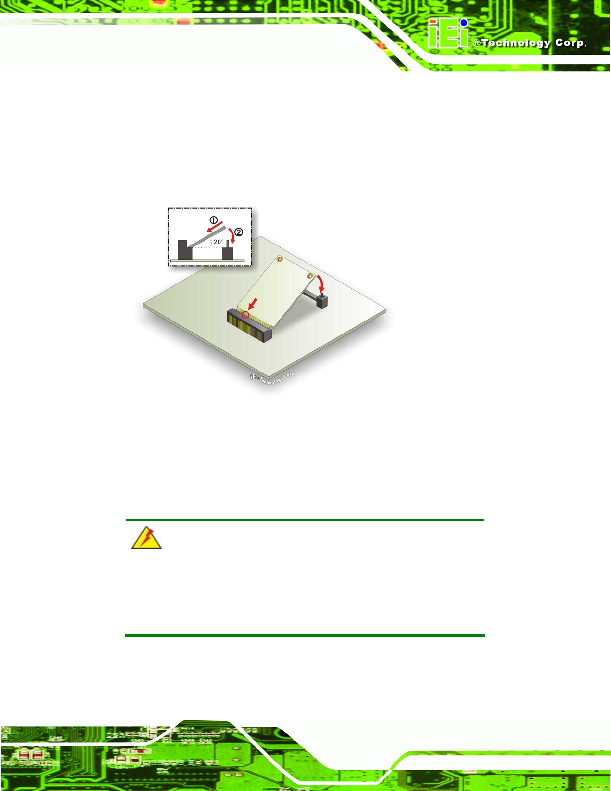
IDS-H61 Digital Signage Player
Step 3: Remove the mSATA module. Push the two spring clips in to release the
mSATA module.
Step 4: Insert a new mSATA module into the socket at an angle. Line up the notch
on the card with the notch on the connector. Slide the mSATA module into the
socket at an angle of about 20º (
Figure 5-3: mSATA Module Installation
Step 5: Push down until the card clips into place. Push the other end of the card
down until it clips into place on the plastic connector.Step 0:
Figure 5-3).
5.2.2 SO-DIMM Replacement
WARNING:
Using incorrectly specified SO-DIMM may cause permanently damage
the IDS-H61. Please make sure the purchased SO-DIMM complies
with the memory specifications of the IDS-H61.
To replace a SO-DIMM memory module into a SO-DIMM socket, please follow the steps
below.
Page 43
Page 54

IDS-H61 Digital Signage Player
Step 1: Remove the top cover by removing the four retention screws on both side panels
(two on each side). See
Step 2: Locate the SO-DIMM. (
Figure 5-1.
83Figure 5-4).
Figure 5-4: SO-DIMM Removal
Step 3: Remove the SO-DIMM by releasing the arms on the SO-DIMM socket. Align the
new SO-DIMM with the socket. The SO-DIMM must be oriented in such a way
that the notch in the middle of the SO-DIMM must be aligned with the plastic
bridge in the socket (
83Figure 5-5).
Step 4: Insert the SO-DIMM. Push the SO-DIMM chip into the socket at an angle
83Figure 5-5).
(
Figure 5-5: SO-DIMM Installation
Step 5: Secure the SO-DIMM. Press the SO-DIMM down until the arms of the
SO-DIMM socket clip into place and secure the SO-DIMM in the socket.Step 0:
Page 44
Page 55

IDS-H61 Digital Signage Player
6 Interface Connectors
Chapter
6
Page 45
Page 56

6.1 Peripheral Interface Connectors
The IDS-H61 series’ motherboard comes with a number of peripheral interface connectors
and configuration jumpers. The connector locations are shown in Figure 6-1. The Pin 1
locations of the on-board connectors are also indicated in the diagrams below. The
connector pinouts for these connectors are listed in the following sections.
IDS-H61 Digital Signage Player
Figure 6-1: Main Board Layout Diagram (Front Side)
Page 46
Page 57

IDS-H61 Digital Signage Player
6.2 Internal Peripheral Connectors
Internal peripheral connectors are found on the motherboard and are only accessible
when the motherboard is outside of the chassis. The table below shows a list of the
peripheral interface connectors on the IDS-H61 motherboard. Pinouts of these connectors
can be found in the following sections.
Connector Type Label
Debug connector 4-pin wafer CN6
Fan connector (1) 4-pin wafer FAN1
Fan connector (2) 4-pin wafer FAN2
PCIe Mini card slot Half-size PCIe Mini card slot CN3
PCIe Mini card slot Full-size PCIe Mini card slot CN5
PCIe Mini card slot (mSATA) Full-size PCIe Mini card slot CN2
RS-485 connector 2-pin wafer CN8
SATA connector 7-pin connector SATA2
SATA power connector 4-pin wafer SATA_PWR1
SD card slot SD card slot CN9
Serial port for debug 10-pin box header COM3
SO-DIMM connector SO-DIMM connector DIMM1
SPI Flash connector 8-pin header JSPI1
Table 6-1: Peripheral Interface Connectors
6.2.1 Fan Connector (FAN1)
PIN NO. DESCRIPTION
1 GND
2 +12V
3 FB
4 PWM
Table 6-2: Fan Connector (FAN1) Pinouts
Page 47
Page 58

6.2.2 Fan Connector (FAN2)
PIN NO. DESCRIPTION
1 GND
2 +12V
3 FB
4 PWM
Table 6-3: Fan Connector (FAN2) Pinouts
6.2.3 Half-Size PCIe Mini Slot (CN3)
PIN NO. DESCRIPTION PIN NO. DESCRIPTION
1 PCIE-WAKE 2 +3.3V
3 N/C 4 GND
IDS-H61 Digital Signage Player
5 N/C 6 +1.5V
7 N/C 8 N/C
9 GND 10 N/C
11 PCIE_CLK- 12 N/C
13 PCIE_CLK+ 14 N/C
15 GND 16 N/C
17 RESET 18 GND
19 N/C 20 +3.3V
21 GND 22 RESET
23 PCIE_RN4 24 +3.3V
25 PCIE_RP4 26 GND
27 GND 28 +1.5V
29 GND 30 SMB_CLK
31 PCIE_TN4 32 SMB_DATA
33 PCIE_TP4 34 GND
35 GND 36 -USBP
Page 48
37 GND 38 +USBP
39 +3.3V 40 GND
41 +3.3V 42 N/C
Page 59
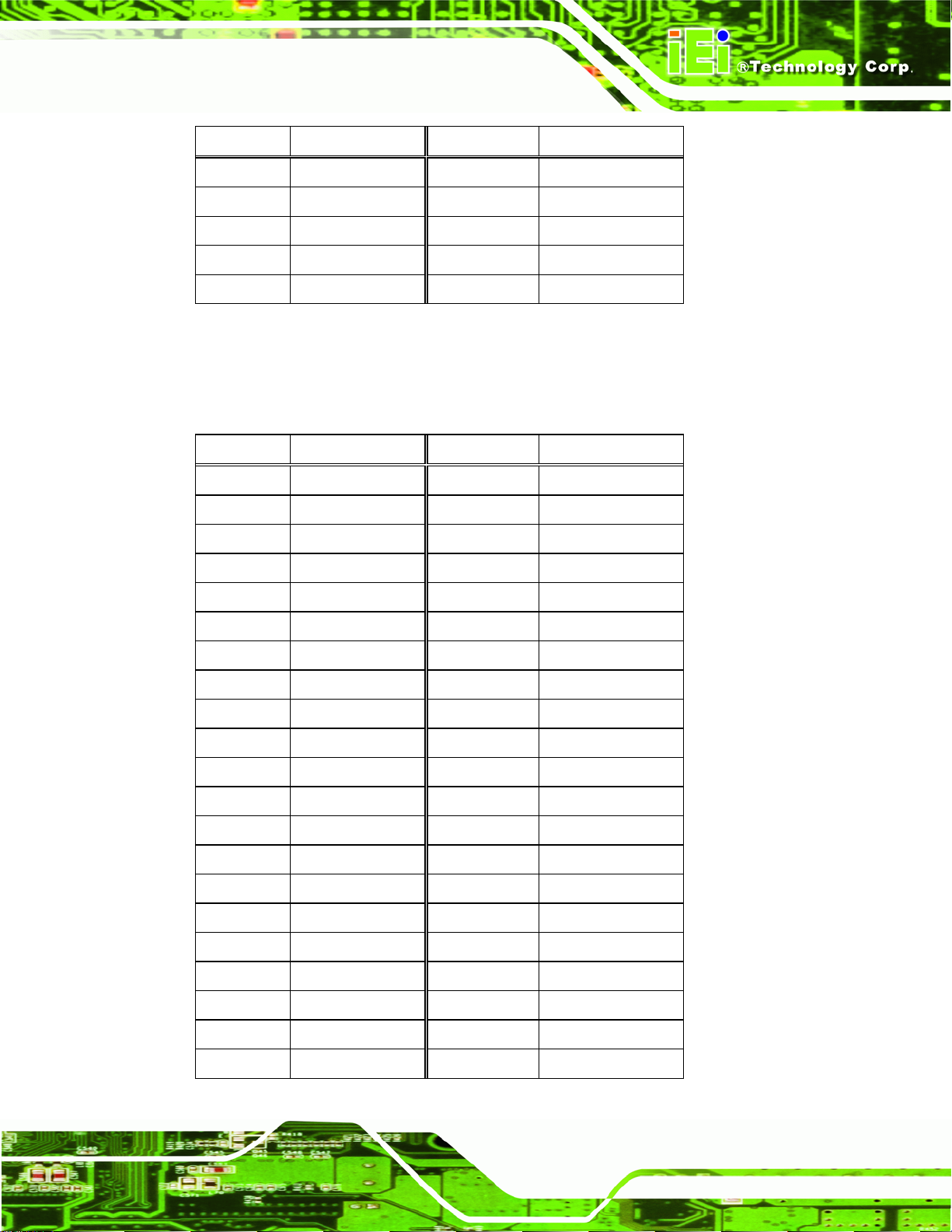
IDS-H61 Digital Signage Player
PIN NO. DESCRIPTION PIN NO. DESCRIPTION
43 GND 44 N/C
45 N/C 46 N/C
47 N/C 48 +1.5V
49 N/C 50 GND
51 N/C 52 +3.3V
Table 6-4: Half-Size PCIe Mini Card Slot (CN3) Pinouts
6.2.4 Full-Size PCIe Mini Slot (CN5)
PIN NO. DESCRIPTION PIN NO. DESCRIPTION
1 PCIE-WAKE 2 +3.3V
3 N/C 4 GND
5 N/C 6 +1.5V
7 N/C 8 N/C
9 GND 10 N/C
11 PCIE_CLK- 12 N/C
13 PCIE_CLK+ 14 N/C
15 GND 16 N/C
17 RESET 18 GND
19 N/C 20 +3.3V
21 GND 22 RESET
23 PCIE_RN4 24 +3.3V
25 PCIE_RP4 26 GND
27 GND 28 +1.5V
29 GND 30 SMB_CLK
31 PCIE_TN4 32 SMB_DATA
33 PCIE_TP4 34 GND
35 GND 36 -USBP
37 GND 38 +USBP
39 +3.3V 40 GND
41 +3.3V 42 N/C
Page 49
Page 60

PIN NO. DESCRIPTION PIN NO. DESCRIPTION
43 GND 44 N/C
45 N/C 46 N/C
47 N/C 48 +1.5V
49 N/C 50 GND
51 N/C 52 +3.3V
Table 6-5: Full-Size PCIe Mini Card Slot (CN5) Pinouts
6.2.5 Full-Size PCIe Mini Slot for mSATA (JP2)
PIN NO. DESCRIPTION PIN NO. DESCRIPTION
1 N/C 2 +3.3V
3 N/C 4 GND
5 N/C 6 N/C
IDS-H61 Digital Signage Player
7 N/C 8 N/C
9 GND 10 N/C
11 N/C 12 N/C
13 N/C 14 N/C
15 GND 16 N/C
17 N/C 18 GND
19 N/C 20 N/C
21 GND 22 N/C
23 SATA_RXP 24 +3.3V
25 SATA_RXN 26 GND
27 GND 28 N/C
29 GND 30 N/C
31 SATA_TXN 32 N/C
33 SATA_TXP 34 GND
35 GND 36 N/C
37 GND 38 N/C
Page 50
39 +3.3V 40 GND
41 +3.3V 42 N/C
43 GND 44 N/C
Page 61

IDS-H61 Digital Signage Player
PIN NO. DESCRIPTION PIN NO. DESCRIPTION
45 N/C 46 N/C
47 N/C 48 N/C
49 N/C 50 GND
51 N/C 52 +3.3V
Table 6-6: Full-Size PCIe Mini Card Slot (CN2) Pinouts
6.2.6 RS-485 Connector (CN8)
PIN NO. DESCRIPTION
1 TXD485#
2 TXD485+
Table 6-7: RS-485 Connector (CN8) Pinouts
6.2.7 SATA Connector (SATA2)
PIN NO. DESCRIPTION
1 GND
2 TX+
3 TX4 GND
5 RX6 RX+
7 GND
Table 6-8: SATA Connector (SATA2) Pinouts
6.2.8 SATA Power Connector (SATA_PWR1)
PIN NO. DESCRIPTION
1 +12V
2 GND
3 GND
4 +5V
Table 6-9: SATA Power Connector (SATA_PWR2) Pinouts
Page 51
Page 62
6.2.9 SPI Flash Connector (JSPI1)
PIN NO. DESCRIPTION PIN NO. DESCRIPTION
1 SPI_VCC 2 GND
3 CS# 4 CLK
5 MISO 6 MOSI
7 N/C 8 N/C
Table 6-10: SPI Flash Connector (JSPI1) Pinouts
IDS-H61 Digital Signage Player
Page 52
Page 63

IDS-H61 Digital Signage Player
A Safety Precautions
Appendix
A
Page 53
Page 64
WARNING:
The precautions outlined in this chapter should be strictly followed.
Failure to follow these precautions may result in permanent damage to
the IDS-H61.
A.1 Safety Precautions
Please follow the safety precautions outlined in the sections that follow:
A.1.1 General Safety Precautions
IDS-H61 Digital Signage Player
Please ensure the following safety precautions are adhered to at all times.
Follow the electrostatic precautions outlined below whenever the IDS-H61
is opened.
Make sure the power is turned off and the power cord is disco nnected
whenever the IDS-H61 is being installed, moved or modified.
Do not apply voltage levels that exceed the specified voltage range.
Doing so may cause fire and/or an electrical shock.
Electric shocks can occur if the IDS-H61 chassis is opened when the
IDS-H61 is running.
Do not drop or insert any objects into the ventilation openings of the
IDS-H61.
If considerable amounts of dust, water, or fluids enter the IDS-H61, turn
off the power supply immediately, unplug the power cord, and contact the
IDS-H61 vendor.
DO NOT:
o Drop the IDS-H61 against a hard surface.
Page 54
o In a site where the ambient temperature exceeds the rated temperature
Page 65

IDS-H61 Digital Signage Player
A.1.2 Anti-static Precautions
WARNING:
Failure to take ESD precautions during the installation of the IDS-H61
may result in permanent damage to the IDS-H61 and severe injury to
the user.
Electrostatic discharge (ESD) can cause serious damage to electronic components,
including the IDS-H61. Dry climates are especially susceptible to ESD. It is therefore
critical that whenever the IDS-H61 is opened and any of the electrical components are
handled, the following anti-static precautions are strictly adhered to.
Wear an anti-static wristband: Wearing a simple anti-static wristband can
help to prevent ESD from damaging any electrical component.
Self-grounding: Before handling any electrical component, touch any
grounded conducting material. During the time the electrical component is
handled, frequently touch any conducting materials that are connected to the
ground.
Use an anti-static pad: When configuring or working with an electrical
component, place it on an antic-static pad. This reduces the possibility of ESD
damage.
Only handle the edges of the electrical component: When handling the
electrical component, hold the electrical component by its edges.
Page 55
Page 66
A.1.3 Product Disposal
CAUTION:
Risk of explosion if battery is replaced by and incorrect type. Only
certified engineers should replace the on-board battery.
Dispose of used batteries according to instructions and local
regulations.
Outside the European Union - If you wish to dispose of used electrical and
electronic products outside the European Union, please contact your local
authority so as to comply with the correct disposal method.
IDS-H61 Digital Signage Player
Within the European Union:
EU-wide legislation, as implemented in each Member State, requires that
waste electrical and electronic products carrying the mark (left) must be
disposed of separately from normal household waste. This includes
monitors and electrical accessories, such as signal cables or power cords.
When you need to dispose of your display products, please follow the
guidance of your local authority, or ask the shop where you purchased the product. The
mark on electrical and electronic products only applies to the current European Union
Member States.
Please follow the national guidelines for electrical and electronic product disposal.
A.2 Maintenance and Cleaning Precautions
When maintaining or cleaning the IDS-H61, please follow the guidelines below.
A.2.1 Maintenance and Cleaning
Page 56
Prior to cleaning any part or component of the IDS-H61, please read the details below.
The interior of the IDS-H61 does not require cleaning. Keep fluids away from
the IDS-H61 interior.
Page 67

IDS-H61 Digital Signage Player
Be cautious of all small removable components when vacuuming the
IDS-H61.
Turn the IDS-H61 off before cleaning the IDS-H61.
Never drop any objects or liquids through the openings of the IDS-H61.
Be cautious of any possible allergic reactions to solvents or chemicals used
when cleaning the IDS-H61.
Avoid eating, drinking and smoking within vicinity of the IDS-H61.
A.2.2 Cleaning Tools
Some components in the IDS-H61 may only be cleaned using a product specifically
designed for the purpose. In such case, the product will be explicitly mentioned in the
cleaning tips. Below is a list of items to use when cleaning the IDS-H61.
Cloth – Although paper towels or tissues can be used, a soft, clean piece of
cloth is recommended when cleaning the IDS-H61.
Water or rubbing alcohol – A cloth moistened with water or rubbing alcohol
can be used to clean the IDS-H61.
Using solvents – The use of solvents is not recommended when cleaning the
IDS-H61 as they may damage the plastic parts.
Vacuum cleaner – Using a vacuum specifically designed for computers is
one of the best methods of cleaning the IDS-H61. Dust and dirt can restrict
the airflow in the IDS-H61 and cause its circuitry to corrode.
Cotton swabs - Cotton swaps moistened with rubbing alcohol or water are
excellent tools for wiping hard to reach areas.
Foam swabs - Whenever possible, it is best to use lint free swabs such as
foam swabs for cleaning.
Page 57
Page 68

IDS-H61 Digital Signage Player
Appendix
B
B BIOS Menu Options
Page 58
Page 69

IDS-H61 Digital Signage Player
B.1 BIOS Configuration Options
Below is a list of BIOS configuration options described in Chapter 4.
System Overview .................................................................................................................27
Memory Information ............................................................................................................27
System Date [xx/xx/xx]........................................................................................................28
System Time [xx:xx:xx].......................................................................................................28
Intel Virtualization Technology [Disabled] ........................................................................30
USB Devices.........................................................................................................................31
Legacy USB Support [Enabled]..........................................................................................31
Smart Fan Function [Enable]..............................................................................................32
H/W Monitor..........................................................................................................................32
DVMT Pre-Allocated [64M] ..................................................................................................33
DVMT Total Gfx Mem [256M]...............................................................................................34
SATA Mode Selection [IDE Mode]......................................................................................34
Restore on AC Power Loss [Last State]............................................................................35
Bootup NumLock State [On]...............................................................................................35
Quiet Boot [Disabled] ..........................................................................................................36
Administrator Password .....................................................................................................37
User Password.....................................................................................................................37
Save Changes and Reset ....................................................................................................38
Discard Changes and Reset ...............................................................................................38
Restore Defaults ..................................................................................................................38
Save as User Defaults .........................................................................................................39
Restore User Defaults .........................................................................................................39
Page 59
Page 70
IDS-H61 Digital Signage Player
Appendix
C
C Watchdog Timer
Page 60
Page 71

IDS-H61 Digital Signage Player
NOTE:
The following discussion applies to DOS environment. IEI support is
contacted or the IEI website visited for specific drivers for more
sophisticated operating systems, e.g., Windows and Linux.
The Watchdog Timer is provided to ensure that standalone systems can always recover
from catastrophic conditions that cause the CPU to crash. This condition may have
occurred by external EMI or a software bug. When the CPU stops working correctly,
Watchdog Timer either performs a hardware reset (cold boot) or a Non-Maskable Interrupt
(NMI) to bring the system back to a known state.
A BIOS function call (INT 15H) is used to control the Watchdog Timer:
INT 15H:
AH – 6FH Sub-function:
AL – 2: Sets the Watchdog Timer’s period.
BL: Time-out value (Its unit-second is dependent on the item “Watchdog
Timer unit select” in CMOS setup).
Table C-1: AH-6FH Sub-function
Call sub-function 2 to set the time-out period of Watchdog Timer first. If the time-out value
is not zero, the Watchdog Timer starts counting down. While the timer value reaches zero,
the system resets. To ensure that this reset condition does not occur, calling sub-function
2 must periodically refresh the Watchdog Timer. However, the Watchdog timer is disabled
if the time-out value is set to zero.
A tolerance of at least 10% must be maintained to avoid unknown routines within the
operating system (DOS), such as disk I/O that can be very time-consuming.
Page 61
Page 72

NOTE:
When exiting a program it is necessary to disable the Watchdog Timer,
otherwise the system resets.
Example program:
; INITIAL TIMER PERIOD COUNTER
;
W_LOOP:
IDS-H61 Digital Signage Player
MOV AX, 6F02H ;setting the time-out value
MOV BL, 30 ;time-out value is 48 seconds
INT 15H
;
; ADD THE APPLICATION PROGRAM HERE
;
CMP EXIT_AP, 1 ;is the application over?
JNE W_LOOP ;No, restart the application
MOV AX, 6F02H ;disable Watchdog Timer
MOV BL, 0 ;
INT 15H
;
; EXIT ;
Page 62
 Loading...