

Page 1

ICECARE-10W Mobile Sales Assistant
MODEL:
ICECARE-10W Series
10.1” Mobile Sales Assistant with
Intel® Core i7/Atom/Celeron® CPU, DDR3 SDRAM,
802.11b/g/n Wireless, Bluetooth, RFID, USB, Micro HDMI,
MSR, SCR, RoHS Compliant, IP 54 Compliant Front Panel
User Manual
Rev. 1.01 – 2 April, 2014
Page i
Page 2

ICECARE-10W Mobile Sales Assistant
Revision
Date Version Changes
2 April, 2014 1.01 Modified the CPU specifications of the model with Intel®
Celeron® processor.
Modified Section
18 December, 2013 1.00 Initial release
3.7: Testing Smart Card Reader
Page ii
Page 3

ICECARE-10W Mobile Sales Assistant
COPYRIGHT NOTICE
In no event will the manufacturer be liable for direct, indirect, special, incidental, or
consequential damages arising out of the use or inability to use the product or
documentation, even if advised of the possibility of such damages.
This document contains proprietary information protected by copyright. All rights are
reserved. No part of this manual may be reproduced by any mechanical, electronic, or
other means in any form without prior written permission of the manufacturer.
TRADEMARKS
Copyright
All registered trademarks and product names mentioned herein are used for identification
purposes only and may be trademarks and/or registered trademarks of their respective
owners.
Page iii
Page 4

ICECARE-10W Mobile Sales Assistant
WARNING
This device complies with Part 15 of the FCC Rules. Operation is subject to the following
two conditions:
(1) this device may not cause harmful interference, and(2) this device must accept any
interference received, including interference that may cause u ndesired operation.
NOTE: This equipment has been tested and found to comply with the limits for a Class
B digital device, pursuant to part 15 of the FCC Rules. These limits are designed to
provide reasonable protection against harmful interference in a residential installation.
This equipment generates, uses and can radiate radio frequency energy and, if not
installed and used in accordance with the instructions, may cause harmful interference
to radio communications.
However, there is no guarantee that interference will not occur in a particular
installation. If this equipment does cause harmful interference to radio or television
reception, which can be determined by turning the equipment off and on, the user is
encouraged to try to correct the interference by one or more of the following measures:
—
Reorient or relocate the receiving antenna.
—
Increase the separation between the equipment and receiver.
—
Connect the equipment into an outlet on a circuit different from that to which the
receiver is connected.
—
Consult the dealer or an experienced radio/ TV technician for help.
You are cautioned that any change or modifications to the equipment not expressly
approve by the party responsible for compliance could void your authority to operate
such equipment.
IMPORTANT NOTE:
FCC Radiation Exposure Statement:
This equipment complies with FCC radiation exposure limits set forth for an
uncontrolled environment. This equipment should be installed and operated with
minimum distance 20cm between the radiator & your body
Page iv
.
Page 5

ICECARE-10W Mobile Sales Assistant
Table of Contents
1 INTRODUCTION.......................................................................................................... 1
1.1 OVERVIEW.................................................................................................................. 2
1.2 FEATURES................................................................................................................... 3
1.3 MODEL VARIATIONS................................................................................................... 3
1.4 FRONT PANEL............................................................................................................. 4
1.4.1 Status Indicators ................................................................................................ 4
1.5 REAR PANEL............................................................................................................... 6
1.6 SIDE PANELS .............................................................................................................. 6
1.7 TOP PANEL ................................................................................................................. 7
1.8 TECHNICAL SPECIFICATIONS ...................................................................................... 7
1.9 DIMENSIONS............................................................................................................... 9
2 UNPACKING ............................................................................................................... 10
2.1 UNPACK THE SYSTEM................................................................................................11
2.2 PACKING LIST............................................................................................................11
3 HARDWARE INSTALLATION................................................................................. 13
3.1 INSTALLATION CONSIDERATIONS.............................................................................. 14
3.2 CHARGE THE SYTEM ................................................................................................ 15
3.3 POWER-UP THE SYSTEM ........................................................................................... 16
3.4 USING RFID READER............................................................................................... 17
3.5 USING BARCODE SCANNER...................................................................................... 20
3.5.1 Barcode Setting................................................................................................ 25
3.6 USING MAGNETIC STRIPE READER .......................................................................... 29
3.7 TESTING SMART CARD READER ............................................................................... 33
4 DRIVER INSTALLATION......................................................................................... 35
4.1 AVAILABLE SOFTWARE DRIVERS .............................................................................. 36
4.2 INTEL® CHIPSET DRIVER......................................................................................... 36
4.3 INTEL® GRAPHICS DRIVER ...................................................................................... 38
4.4 AUDIO DRIVER......................................................................................................... 39
Page v
Page 6

4.5 BLUETOOTH DRIVER................................................................................................ 41
4.6 WIRELESS LAN DRIVER .......................................................................................... 43
4.7 RFID DRIVER .......................................................................................................... 45
5 BIOS SETUP................................................................................................................ 48
5.1 INTRODUCTION......................................................................................................... 49
5.1.1 Starting Setup................................................................................................... 49
5.1.2 Using Setup...................................................................................................... 49
5.1.3 Getting Help..................................................................................................... 50
5.1.4 BIOS Menu Bar................................................................................................ 50
5.2 MAIN........................................................................................................................ 51
5.3 ADVANCED............................................................................................................... 52
5.3.1 ACPI Settings................................................................................................... 53
5.3.2 RTC Wake Settings........................................................................................... 54
5.3.3 T rusted Computing........................................................................................... 55
ICECARE-10W Mobile Sales Assistant
5.3.4 CPU Configuration.......................................................................................... 56
5.3.5 SATA Configuration......................................................................................... 57
5.3.6 Intel(R) Rapid Start Technology....................................................................... 58
5.3.7 USB Configuration........................................................................................... 59
5.3.8 iWDD Serial Ports Configuration ................................................................... 60
5.3.8.1 Serial Port 1 Configuration....................................................................... 61
5.3.8.2 Serial Port 2 Configuration....................................................................... 62
5.3.9 H/W Monitor.................................................................................................... 63
5.3.10 Serial Port Console Redirection.................................................................... 63
5.3.11 IEI Feature..................................................................................................... 64
5.4 CHIPSET ................................................................................................................... 65
5.4.1 PCH-IO Configuration .................................................................................... 66
5.4.2 System Agent (SA) Configuration .................................................................... 69
5.4.2.1 Graphics Configuration............................................................................. 69
5.4.2.2 Memory Configuration ............................................................................. 71
5.5 BOOT........................................................................................................................ 72
5.6 SECURITY................................................................................................................. 74
5.7 EXIT......................................................................................................................... 74
A SAFETY PRECAUTIONS.........................................................................................76
Page vi
Page 7

ICECARE-10W Mobile Sales Assistant
A.1 SAFETY PRECAUTIONS ............................................................................................ 77
A.1.1 General Safety Precautions............................................................................. 77
A.1.2 Anti-static Precautions.................................................................................... 78
A.1.3 Product Disposal............................................................................................. 79
A.2 MAINTENANCE AND CLEANING PRECAUTIONS........................................................ 79
A.2.1 Maintenance and Cleaning.............................................................................. 79
A.2.2 Cleaning Tools................................................................................................. 80
B BIOS OPTIONS .......................................................................................................... 82
C TERMINOLOGY ....................................................................................................... 85
D WA TCHDOG TIMER ................................................................................................89
E HAZARDOUS MATERIALS DISCLOSURE ......................................................... 92
E.1 HAZARDOUS MATERIALS DISCLOSURE TABLE FOR IPB PRODUCTS CERTIFIED AS
ROHS COMPLIANT UNDER 2002/95/EC WITHOUT MERCURY ....................................... 93
Page vii
Page 8

ICECARE-10W Mobile Sales Assistant
List of Figures
Figure 1-1: ICECARE-10W Series..................................................................................................2
Figure 1-2: Front Panel ..................................................................................................................4
Figure 1-3: Front Panel LED Indicators........................................................................................4
Figure 1-4: Rear Panel....................................................................................................................6
Figure 1-5: Side Panels..................................................................................................................6
Figure 1-6: Top Panel.....................................................................................................................7
Figure 1-7: Dimensions (units in mm)..........................................................................................9
Figure 3-1: Power Input Connector and Power LED Indicator.................................................15
Figure 3-2: Windows Embedded 7 Power Management Screen..............................................16
Figure 3-3: Power Button and Power LED Location.................................................................16
Figure 3-4: PcscTool Location....................................................................................................18
Figure 3-5: NXP PCSC Tool Screen............................................................................................18
Figure 3-6: NXP PCSC Tool – Mode Selection...........................................................................19
Figure 3-7: NXP PCSC Tool – Reader Selection........................................................................19
Figure 3-8: NXP PCSC Tool – Select the Reader.......................................................................19
Figure 3-9: NXP PCSC Tool – Read RFID Card..........................................................................20
Figure 3-10: RFID Reader Location.............................................................................................20
Figure 3-11: Barcode Scanner Program Location.....................................................................21
Figure 3-12: EasySet InstallShield Wizard.................................................................................22
Figure 3-13: Menu Button and Barcode Status Indicator.........................................................22
Figure 3-14: EasySet Window .....................................................................................................23
Figure 3-15: EasySet – Communication.....................................................................................23
Figure 3-16: Device Selection Window.......................................................................................24
Figure 3-17: Communication – Disconnect ...............................................................................24
Figure 3-18: Barcode Information Display Area........................................................................25
Figure 3-19: Barcode Parameters...............................................................................................26
Figure 3-20: Symbologies............................................................................................................27
Figure 3-21: Operating Settings..................................................................................................27
Figure 3-22: Scanning/Triggering...............................................................................................28
Figure 3-23: Beeps/Green Indicator LED ...................................................................................28
Page viii
Page 9

ICECARE-10W Mobile Sales Assistant
Figure 3-24: Check COM Port Information for MSR..................................................................30
Figure 3-25: 3DesHeadV1.3 Demo Program Location ..............................................................30
Figure 3-26: 3DesHeadV1.3 – Open COM...................................................................................31
Figure 3-27: 3DesHeadV1.3 – Data Read....................................................................................31
Figure 3-28: Swipe a Magnetic Stripe Card................................................................................32
Figure 3-29: Magnetic Stripe Card Information.........................................................................32
Figure 3-30: Insert Smart Card....................................................................................................33
Figure 3-31: Smart Card Reader Testing 1.................................................................................33
Figure 3-32: Smart Card Reader Testing 2.................................................................................34
Figure 4-1: Chipset Driver Location............................................................................................37
Figure 4-2: Intel® Chipset Device Software...............................................................................37
Figure 4-3: Graphics Driver Location.........................................................................................38
Figure 4-4: Intel® Graphics Driver InstallShield Wizard...........................................................39
Figure 4-5: Speaker and Microphone Driver Location..............................................................40
Figure 4-6: Realtek HD Audio Driver InstallShield Wizard .......................................................41
Figure 4-7: Bluetooth Driver Location........................................................................................42
Figure 4-8: Bluetooth Driver InstallShield Wizard.....................................................................43
Figure 4-9: Wireless LAN Driver Location .................................................................................44
Figure 4-10: Bluetooth Driver InstallShield Wizard...................................................................45
Figure 4-11: RFID Driver Location ..............................................................................................46
Figure 4-12: RFID Driver Folder ..................................................................................................46
Figure 4-13: RFID Driver Installation ..........................................................................................47
Page ix
Page 10

ICECARE-10W Mobile Sales Assistant
List of Tables
Table 1-1: Model Variations...........................................................................................................3
Table 1-2: Status Indicators...........................................................................................................5
Table 1-3: Technical Specifications..............................................................................................8
Table 2-1: Packing List.................................................................................................................12
Table 5-1: BIOS Navigation Keys................................................................................................50
Page x
Page 11

ICECARE-10W Mobile Sales Assistant
BIOS Menus
BIOS Menu 1: Main.......................................................................................................................51
BIOS Menu 2: Advanced..............................................................................................................52
BIOS Menu 3: ACPI Configuration..............................................................................................53
BIOS Menu 4: RTC Wake Settings..............................................................................................54
BIOS Menu 5: Trusted Computing..............................................................................................55
BIOS Menu 6: CPU Configuration...............................................................................................56
BIOS Menu 7: SATA Configuration.............................................................................................57
BIOS Menu 8: Intel(R) Rapid Start Technology .........................................................................58
BIOS Menu 9: USB Configuration...............................................................................................59
BIOS Menu 10: iWDD Serial Ports Configuration......................................................................60
BIOS Menu 11: Serial Port 1 Configuration Menu.....................................................................61
BIOS Menu 12: Hardware Health Configuration........................................................................63
BIOS Menu 13: Serial Port Console Redirection.......................................................................64
BIOS Menu 14: IEI Feature...........................................................................................................65
BIOS Menu 15: Chipset................................................................................................................66
BIOS Menu 16: PCH-IO Configuration........................................................................................66
BIOS Menu 17: System Agent (SA) Configuration....................................................................69
BIOS Menu 18: Graphics Configuration.....................................................................................70
BIOS Menu 19: Memory Configuration.......................................................................................71
BIOS Menu 20: Boot.....................................................................................................................72
BIOS Menu 21: Security...............................................................................................................74
BIOS Menu 22: Exit.......................................................................................................................75
Page xi
Page 12

Page 13

ICECARE-10W Mobile Sales Assistant
1 Introduction
Chapter
1
Page 1
Page 14

1.1 Overview
ICECARE-10W Mobile Sales Assistant
Figure 1-1: ICECARE-10W Series
The ICECARE-10W Series is a mobile sales assistant with a 10.1 inch touchscreen and
an IP 54 compliant front panel. The ICECARE-10W Series features an Intel® Atom™
processor N2600, Intel® Celeron® processor 1007U or Intel® Core™ i7-3517U processor
with DDR3 SDRAM memory.
Storage needs are met by the preinstalled 32 GB mSATA PCIe Mini module with Windows
Embedded Standard 7 P operating system.
Wireless networking is enabled through an 802.11b/g/n wireless adapter. A Bluetooth v3.0
module provides a connection to Bluetooth devices. Two USB 2.0 ports and one Micro
HDMI port are available on the side panel for peripherals.
The ICECARE-10W Series also features an RFID reader, an optional barcode scanner, an
optional magnetic stripe card reader and an optional smart card reader for advanced data
acquisition.
Page 2
Page 15

ICECARE-10W Mobile Sales Assistant
1.2 Features
Some of the standard features of the ICECARE-10W Series include:
10.1” TFT XGA LCD
Intel® Core™ i7-3517U processor, Intel® Atom™ processor N2600 or Intel®
Celeron® processor 1007U supported
Support RFID reader
Support Bluetooth and Wi-Fi wireless connection
Optional 1D/2D barcode scanner, optional magnetic stripe reader and
optional smart card reader
IP 54 compliant front panel protection
Windows® Embedded Standard 7 P OS
RoHS compliant
1.3 Model Variations
There are six models of the ICECARE-10W Series. All of the models support 802.11b/g/n
wireless and Bluetooth connection and are equipped with the multi-touch projected
capacitive touchscreen and a 32 GB SSD module. The model numbers and model
variations are listed below.
ICECARE-10W CPU Memory Barcode MSR SCR IPS Panel
-R10 Intel® Atom
N2600 1.6GHz
-ET-R10 Intel® Atom
N2600 1.6GHz
-CE-R10 Intel® Celeron®
1007U 1.5GHz
-CE-ET-R10 Intel® Celeron®
1007U 1.5GHz
-I7-R10 Intel® Core
2.0 GB 1D/2D Yes Yes N/A
2.0 GB N/A N/A N/A N/A
4.0 GB 1D/2D Yes Yes N/A
4.0 GB N/A N/A N/A N/A
4.0 GB 1D/2D Yes Yes Yes
i7-3517U 1.9GHz
-I7-ET-R10 Intel® Core
i7-3517U 1.9GHz
4.0 GB N/A N/A N/A Yes
Table 1-1: Model Variations
Page 3
Page 16
1.4 Front Panel
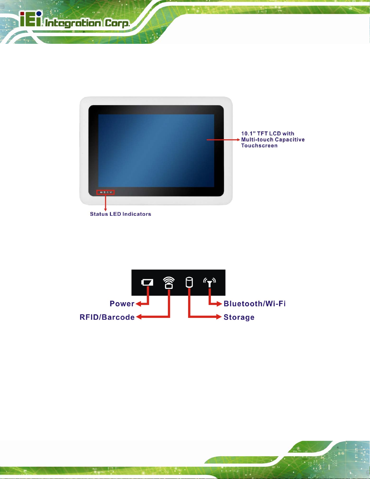
The front panel of the ICECARE-10W Series has a 10.1” TFT LCD with a multi-touch
proected capacitive touchscreen. Four LED indicators are also located on the front panel.
ICECARE-10W Mobile Sales Assistant
Figure 1-2: Front Panel
1.4.1 Status Indicators
Figure 1-3: Front Panel LED Indicators
There are four LED indicators on the front panel of the ICECARE-10W Series as show in
the figure above. Following are descriptions of their functions:
Page 4
Page 17
ICECARE-10W Mobile Sales Assistant
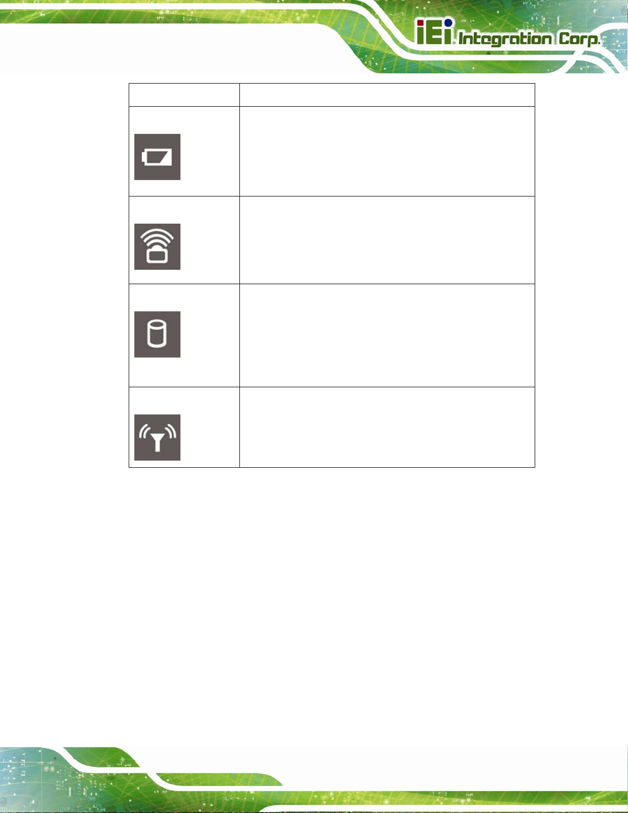
Status Indicator Description
Power/Battery
RFID/Barcode
Storage
Bluetooth/Wi-Fi
Off: the system is off or the system is fully charged
Solid red: the system is being charged.
Blinking red: the battery is low (below 9%).
Solid blue: the system is turned on.
Solid purple: the system is turned on and being charged.
Off: the barcode scanner or the RFID reader is off
Solid red: the barcode scanner is turned on
Solid blue: the RFID reader is turned on
Solid purple: the barcode scanner and the RFID reader are
both turned on
Off: the hard drive is not accessed (when the system is on) or
the system is off without standby power (AC power off).
Solid red: the hard drive is accessed
Solid blue: the system is off and being charged (or with
standby power)
Blinking blue: The system suspends to RAM (S3)
Off: Bluetooth RF is off or Wi-Fi RF is not active
Solid red: Bluetooth RF is turned on
Solid blue: Wi-Fi RF is active
Table 1-2: Status Indicators
Solid purple: Bluetooth and Wi-Fi are both turned on
Page 5
Page 18
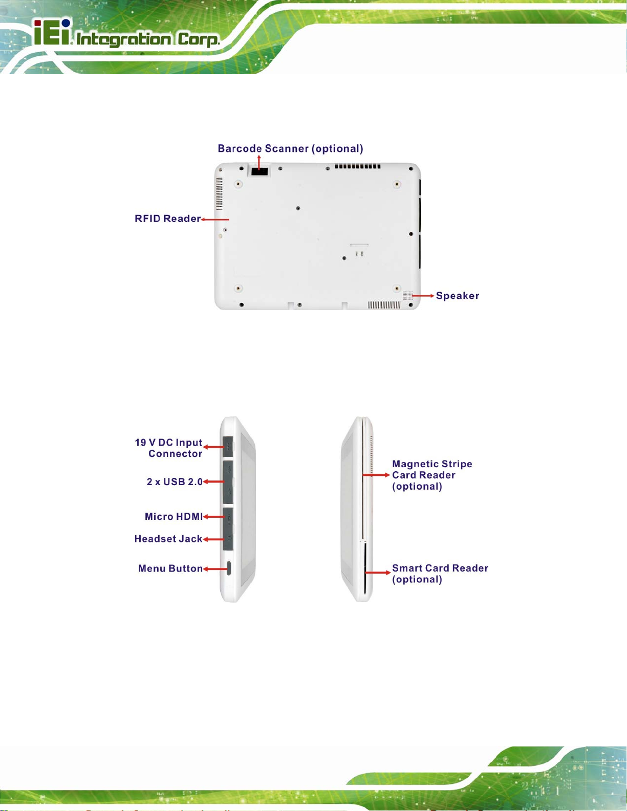
1.5 Rear Panel
The rear panel has an RFID reader, a speaker and an optional barcode scanner.
Figure 1-4: Rear Panel
ICECARE-10W Mobile Sales Assistant
1.6 Side Panels
The side panels have connectors, button and readers as shown in 473Figure 1-5.
Figure 1-5: Side Panels
Page 6
The menu button has two functions:
Short press: turn on the barcode scanner
Long press: act as a Ctrl+ Alt+Del key combination
Page 19
ICECARE-10W Mobile Sales Assistant
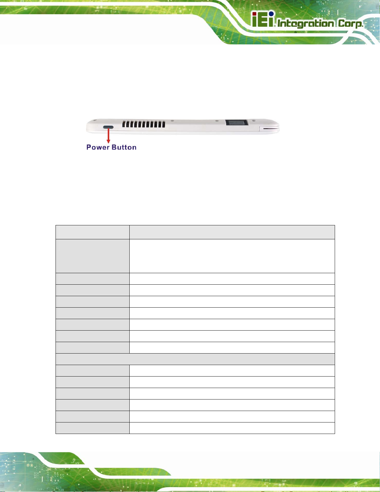
1.7 Top Panel
The power button is located on the top panel. To power-up the system, long press the
power button for few seconds until the power status LED on the front panel lights up in
blue.
Figure 1-6: Top Panel
1.8 Technical Specifications
The technical specifications for the ICECARE-10W Series are listed in the table below.
System ICECARE-10W Series
CPU and Chipset 1.6GHz Intel® Atom™ processor N2600 with Intel® NM10 chipset,
1.5GHz Intel® Celeron® processor 1007U with Intel® HM76 chipset or
1.9GHz Intel® Core™ i7-3517U processor with Intel® HM76 chipset
Memory On-board 4.0 GB 1333 MHz DDR3 SDRAM (2.0 GB for N2600 models)
OS Microsoft Windows Embedded Standard 7 P (WES7P)
Storage 1 x 32 GB mSATA PCIe Mini module with 3Gb/s data transfer rate
Audio 1 x Speaker
Barcode Scanner 1D laser/2D imager barcode scanner (optional)
MSR 1 x Magnetic stripe card reader with hardware encryption (optional)
SCR 1 x Smart card reader (optional)
Display
LCD 10.1” TFT LCD with projected capacitive touchscreen
Max. Resolution 1280 x 800 (WXGA)
Brightness 250 cd/m2 (350 cd/m2 for I7 models)
Viewing Angle (H/V) 150/145
Backlight LED backlight
Touchscreen Multi-touch capacitive screen with five simultaneous-detection points
Page 7
Page 20

Communication
Wireless LAN 802.11b/g/n
Bluetooth Bluetooth v3.0
RFID 13.56 MHz RFID compliant with 14443A and 14443B
Power
Power Input 19 V DC input
Power Adapter Input AC: 100 V ~ 240 V
Output DC: 19 V DC, 2.1 A
Battery 14.8 V 3500 mAh Lithium Ion Battery (non-removable)
Physical Character
Construction Material Plastic
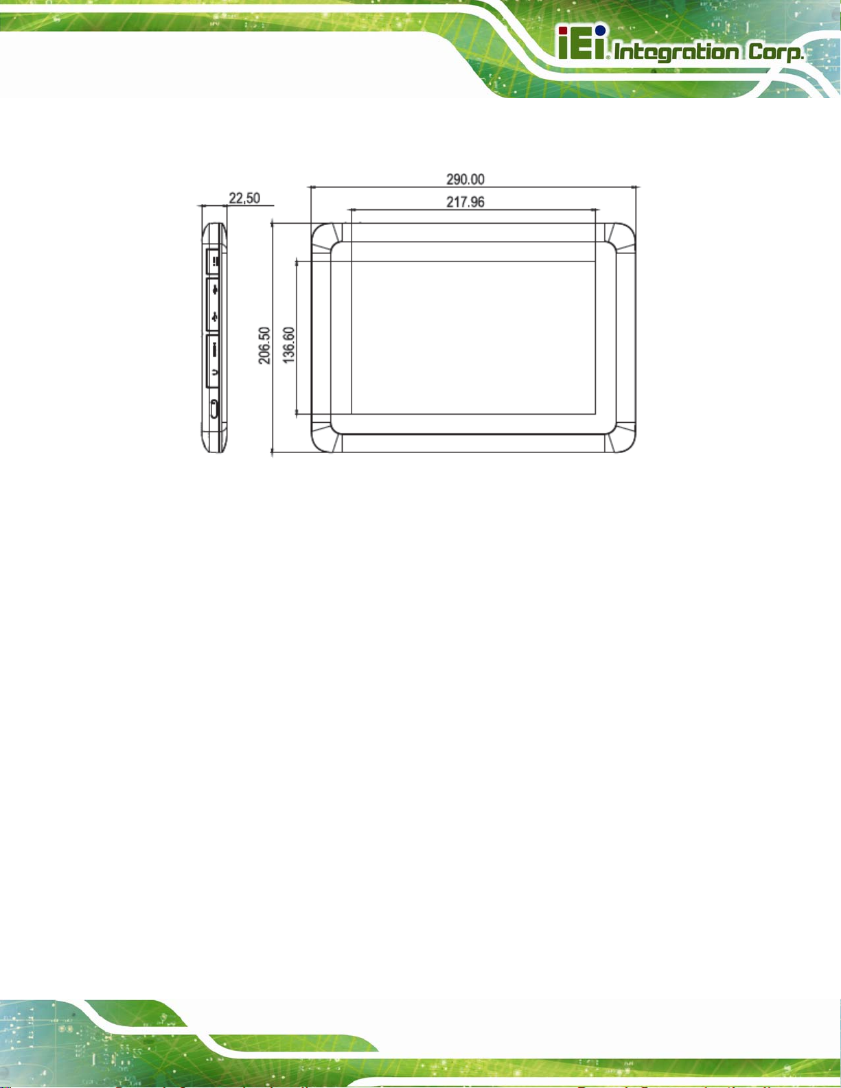
Dimensions (W x H x D) 290.0 mm x 206.5 mm x 22.5 mm
Operation Temperature 0ºC ~ 40ºC
Storage Temperature -20ºC ~ 60ºC
ICECARE-10W Mobile Sales Assistant
Humidity 5% ~ 95% non-condensing
Net weight 1.2 kg
IP level (front panel) IP 54
Drop Survival 1.2 m with optional protective cover
Safety CE, FCC Class B, FCC ID
Connectors and Buttons
I/O Ports and Buttons 1 x 19 V DC input connector
2 x USB 2.0 ports
1 x Micro HDMI port
1 x Headset jack
1 x Menu button
1 x Power button
1 x Magnetic stripe card reader (optional)
1 x Smart card reader (optional)
Front Panel LED
Indicators
1 x Power/Battery status LED
1 x Barcode/RFID status LED
1 x Storage LED
1 x Wi-Fi LED
Table 1-3: Technical Specifications
Page 8
Page 21
ICECARE-10W Mobile Sales Assistant
1.9 Dimensions
Figure 1-7: Dimensions (units in mm)
Page 9
Page 22

ICECARE-10W Mobile Sales Assistant
Chapter
2
2 Unpacking
Page 10
Page 23

ICECARE-10W Mobile Sales Assistant
2.1 Unpack the System
To unpack the ICECARE-10W Series, follow the steps below:
WARNING!
Only remove the protective plastic cover stuck to the front screen after
installation. The plastic layer protects the monitor surface during
installation process.
Step 1: Carefully cut the tape sealing the box. Only cut deep enough to break the tape.
Step 2: Open the box.
Step 3: Lift the ICECARE-10W Series out of the boxes.
Step 4: Remove the peripheral parts box from the main box. Step 0:
2.2 Packing List
NOTE:
If any of the components listed in the checklist below are missing, do
not proceed with the installation. Contact the IEI reseller or vendor the
ICECARE-10W Series was purchased from or contact an IEI sales
representative directly by sending an email to
The ICECARE-10W Series is shipped with the following components:
31sales@ieiworld.com.tw.
Page 11
Page 24
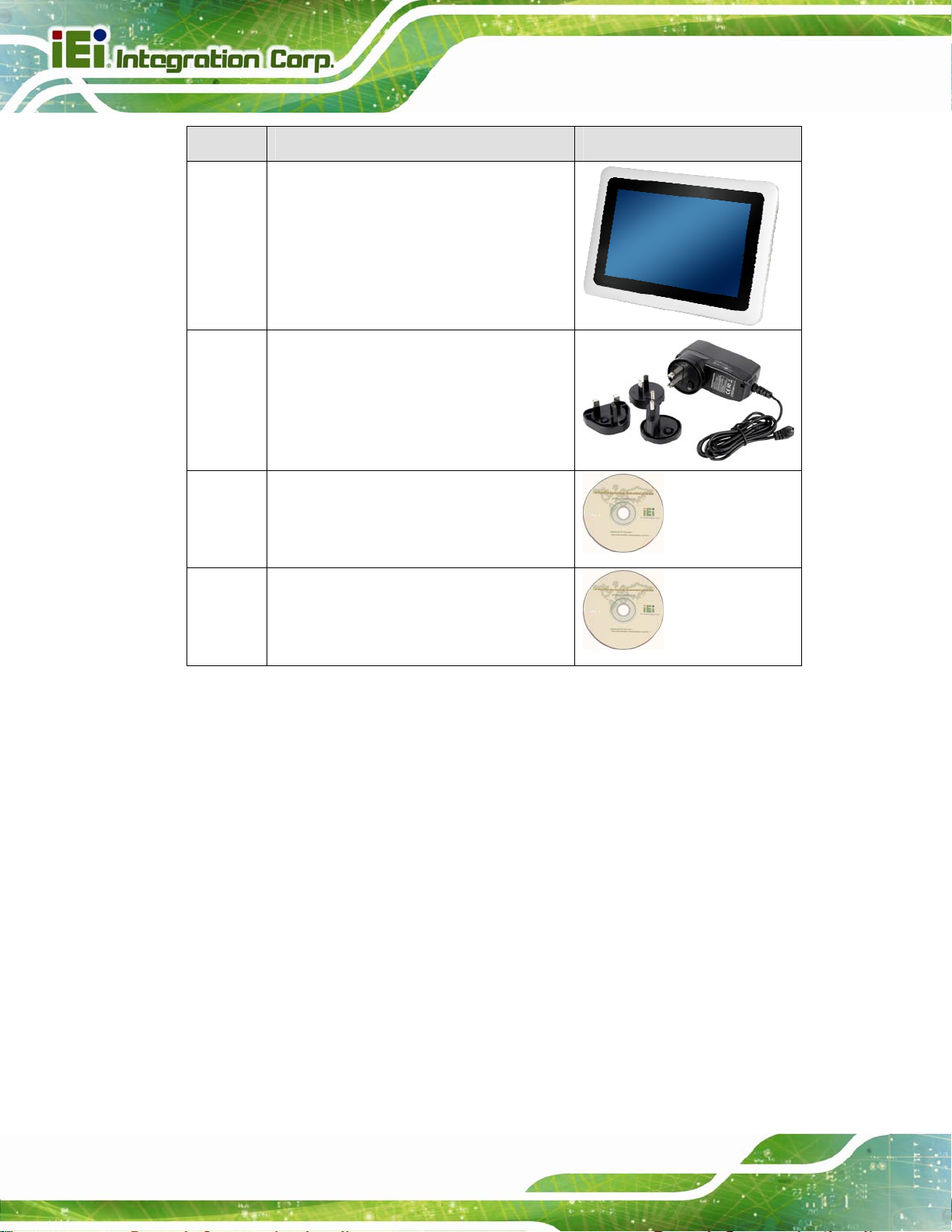
Quantity Item Image
1 ICECARE-10W Series mobile sales
assistant
1 Power adapter
1 Utility CD
ICECARE-10W Mobile Sales Assistant
1 Recovery CD
Table 2-1: Packing List
Page 12
Page 25

ICECARE-10W Mobile Sales Assistant
3 Hardware Installation
Chapter
3
Page 13
Page 26

3.1 Installation Considerations
NOTE:
The following installation notices and installation considerations should
be read and understood before installation. All installation notices must
be strictly adhered to. Failing to adhere to these precautions may lead
to severe damage and injury to the person performing the installation.
WARNING:
The installation instructions described in this manual should be
ICECARE-10W Mobile Sales Assistant
carefully followed in order to prevent damage to the components and
injury to the user.
Before and during the installation please DO the following:
Read the user manual:
The user manual provides a complete description of the ICECARE-10W
Series installation instructions and configuration options.
Wear an electrostatic discharge cuff (ESD):
Electronic components are easily damaged by ESD. Wearing an ESD cuff
removes ESD from the body and helps prevent ESD damage.
Place the ICECARE-10W Series on an antistatic pad:
When installing or configuring the motherboard, place it on an antistatic pad.
This helps to prevent potential ESD damage.
Turn all power to the ICECARE-10W Series off:
When working with the ICECARE-10W Series, make sure that it is
Page 14
disconnected from all power supplies and that no electricity is being fed into
the system.
Before and during the installation of the ICECARE-10W Series DO NOT:
Page 27
ICECARE-10W Mobile Sales Assistant
Remove any of the stickers on the PCB board. These stickers are required for
warranty validation.
Use the product before verifying all the cables and power connectors are
properly connected.
Allow screws to come in contact with the PCB circuit, connector pins, or its
components.
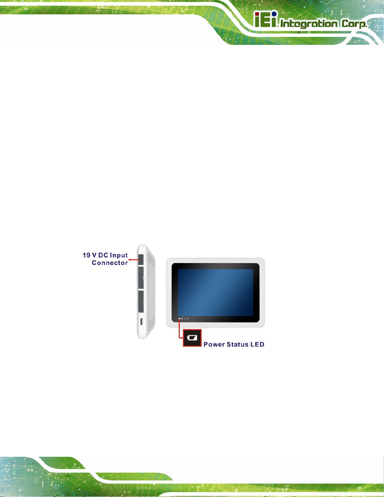
3.2 Charge the Sytem
To charge the ICECARE-10W Series, follow the steps below.
Step 1: Connect the ICECARE-10W Series with a power source through the power
adapter came with the package.
Step 2: The system starts to charge the battery and the power status LED lights up in
red indicating the battery is being charged. When the battery is fully charged, the
power status LED turns off.
Figure 3-1: Power Input Connector and Power LED Indicator
Step 3: The user can also turn on the system to check the battery capacity via the
Windows Embedded 7 power management screen (
73Figure 3-2).
Page 15
Page 28
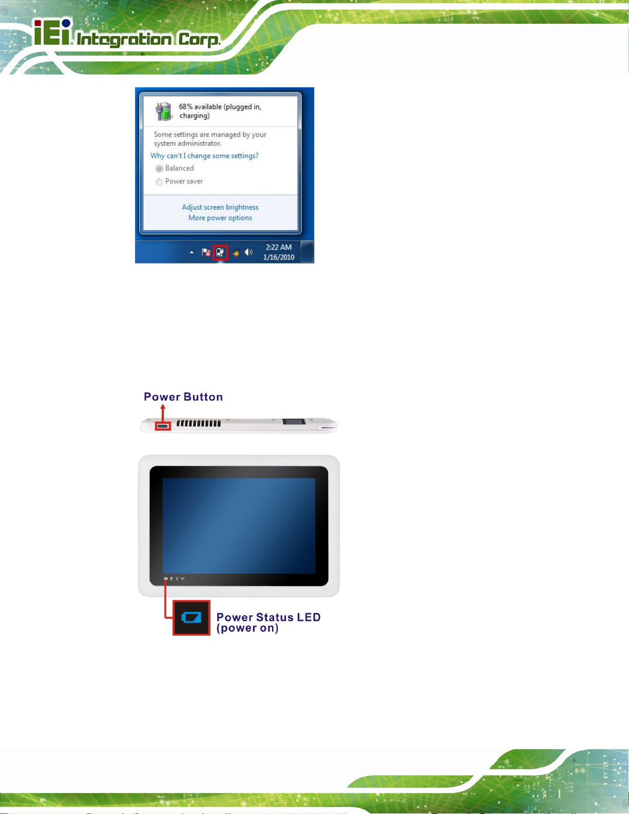
Figure 3-2: Windows Embedded 7 Power Management Screen
3.3 Power-up the System
To power-up the system, push the power button on the top panel for few seconds until the
ICECARE-10W Mobile Sales Assistant
power status LED on the front panel lights up in blue.
Figure 3-3: Power Button and Power LED Location
Page 16
Page 29

ICECARE-10W Mobile Sales Assistant
NOTE:
When the battery is low (below 9%), the power status LED blinks in red.
Please refer to the instruction described in Section
sytem.
3.4 Using RFID Reader
There is a RFID reader on the rear panel. To use the RFID reader, follow the steps below.
Step 1: Check the RFID status indicator on the front panel to make sure the RFID
function is enabled (see Section
in the BIOS menu. If the RFID reader is disabled, please go to Chipset Æ
PCH-IO Configuration BIOS menu to enable it (refer to Section
Step 2: Follow the instruction described in Section
Step 3: Double click the PcscTool icon in the RFID folder in the driver CD.
3.1 to charge the
1.4.1). The RFID function is enabled by default
5.4.1).
4.7 to install the RFID driver.
Page 17
Page 30
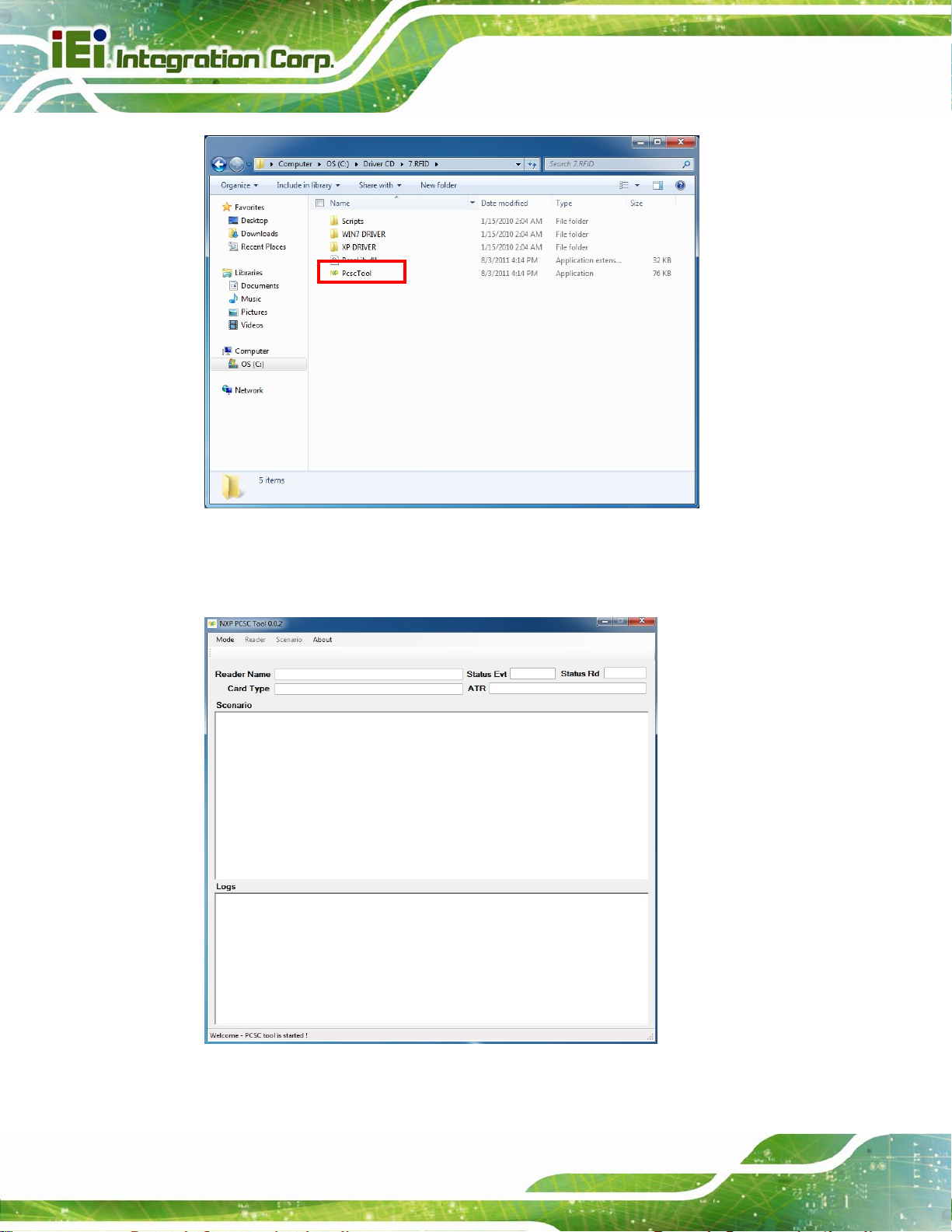
ICECARE-10W Mobile Sales Assistant
Figure 3-4: PcscTool Location
Step 4: The NXP PCSC Tool window appears (
3Figure 3-5).
Page 18
Figure 3-5: NXP PCSC Tool Screen
Page 31

ICECARE-10W Mobile Sales Assistant
Step 5: Select Automatic from the Mode menu (3Figure 3-6).
Figure 3-6: NXP PCSC Tool – Mode Selection
Step 6: Choose Select a Reader from the Reader menu (
3Figure 3-7).
Figure 3-7: NXP PCSC Tool – Reader Selection
Step 7: The Select the reader window prompts. Select a RFID reader and click OK. See
Figure 3-8.
Figure 3-8: NXP PCSC Tool – Select the Reader
Page 19
Page 32

Step 8: Click the Arrow button shown in Figure 3-9 to read RFID card.
Figure 3-9: NXP PCSC Tool – Read RFID Card
Step 9: Use the RFID reader to read a RFID card. The RFID reader is located on the
ICECARE-10W Mobile Sales Assistant
rear panel as shown in
Scenario and Logs columns of the PCSC Tool.
Figure 3-10: RFID Reader Location
3.5 Using Barcode Scanner
Figure 3-10. The card information will be shown in the
Page 20
Some models of the ICECARE-10W Series have a barcode scanner on the rear panel. To
use the barcode scanner, follow the steps below.
Step 1: Check the barcode status indicator on the front panel to make sure the barcode
function is enabled (see Section
default in the BIOS menu. If the barcode scanner is disabled, please go to
1.4.1). The barcode function is enabled by
Page 33

ICECARE-10W Mobile Sales Assistant
Chipset Æ PCH-IO Configuration BIOS menu to enable it (refer to Section
5.4.1).
Step 2: Install EasySet barcode scanner program. Select 4.BARCODE from the list of
the driver CD as shown in
573Figure 3-11.
Figure 3-11: Barcode Scanner Program Location
Step 3: Double click the setup file in the folder. The Easyset InstallShield Wizard screen
appears (
Figure 3-12). Follow the step-by-step instruction of the installation
wizard to install the EasySet barcode scanner program
Page 21
Page 34

ICECARE-10W Mobile Sales Assistant
Figure 3-12: EasySet InstallShield Wizard
Step 4: Push the Menu button on the right side panel to turn on the barcode scanner.
The barcode status indicator on the front panel lights up in red (if the RFID
reader is enabled at the same time, the indicator will turns from blue to purple).
Figure 3-13: Menu Button and Barcode Status Indicator
Page 22
Step 5: Double click the EasySet icon on the desktop. The EasySet window appears
3Figure 3-14).
(
Page 35

ICECARE-10W Mobile Sales Assistant
Figure 3-14: EasySet Window
Step 6: Click Communication on the tool bar and click Select communication
interface from the drop-down menu (
3Figure 3-15).
Figure 3-15: EasySet – Communication
Step 7: The Device Selection window appears (
3Figure 3-16). Select Communication
Port (COM2) and click OK.
Page 23
Page 36

ICECARE-10W Mobile Sales Assistant
Figure 3-16: Device Selection Window
Step 8: To check if the barcode scanner is connected to the EasySet, click
Communication again and see if the original option (Connect) has been
changed to Disconnect.
Figure 3-17: Communication – Disconnect
Step 9: Scan a barcode and the barcode number will be displayed on the right side
Page 24
3Figure 3-18). Step 0:
(
Page 37

ICECARE-10W Mobile Sales Assistant
Figure 3-18: Barcode Information Display Area
3.5.1 Barcode Setting
All of the barcode parameters can be modified through EasySet. To be able to modify the
parameters, please make sure to connect the EasySet with the barcode scanner (refer to
Section
Step 1: The left side of the EasySet window (
33.5). Follow the steps below to modify the parameters.
3Figure 3-19) displays all parameters that
can be configured.
Page 25
Page 38

ICECARE-10W Mobile Sales Assistant
Figure 3-19: Barcode Parameters
Step 2: Use the Symbologies section to setup the format that can be read by the
barcode scanner (EA15). In the default setting, only the PDF417 format of 2-D
barcodes is enabled. If other formats are needed, the user must enable them
here. Take Aztec as an example. The Aztec is disabled (the Disable option is
checked). Double click the Enable option to enable Aztec format. See
3Figure
3-20.
Page 26
Page 39

ICECARE-10W Mobile Sales Assistant
Figure 3-20: Symbologies
Step 3: Use the Operating settings section to configure barcode triggering modes,
decoding security and beeps, etc.
Figure 3-21: Operating Settings
Step 4: In the Scanning/Triggering section of operating settings, the user can set the
triggering mode, continuous, level, etc.
Page 27
Page 40

ICECARE-10W Mobile Sales Assistant
Figure 3-22: Scanning/Triggering
Step 5: In the Beeps/LEDs section of operating settings, the user can configure the
beep sound of the barcode scanner. Step 0:
Page 28
Figure 3-23: Beeps/Green Indicator LED
Page 41

ICECARE-10W Mobile Sales Assistant
NOTE:
If no beep sound, please check if the “rtkhdaud.dat” file is in
C:\windows\system32\drivers
3.6 Using Magnetic Stripe Reader
Some models of the ICECARE-10W Series have a magnetic stripe reader (MSR) on the
left panel. To test the magnetic stripe reader, follow the steps below.
Step 1: Check which COM port is used for the MSR connection. Right click
“Computer” from the start menu and select “Manage” (
Computer Management window appears. Select “Device Manager” from the left
panel and look for the COM port information on the right panel.
Figure 3-24). The
Page 29
Page 42

Figure 3-24: Check COM Port Information for MSR
ICECARE-10W Mobile Sales Assistant
Step 2: Launch the 3DesHeadV1.3 demo program. Select 6.MSR from the list of the
driver CD. Double click the 3DesHeadV1.3 icon from the 3DesHeadV1.3 folder
to launch it (
Figure 3-25).
Page 30
Figure 3-25: 3DesHeadV1.3 Demo Program Location
Page 43

ICECARE-10W Mobile Sales Assistant
Step 3: Select the COM port connected to the MSR according to the information gained
from Step 2. Then, click the Open Com button. See
Figure 3-26: 3DesHeadV1.3 – Open COM
Figure 3-26.
Step 4: Click the Data Read button to start reading the card information from the MSR.
Figure 3-27: 3DesHeadV1.3 – Data Read
Page 31
Page 44

Step 5: Swipe a magnetic stripe card through the MSR (Figure 3-28).
Figure 3-28: Swipe a Magnetic Stripe Card
ICECARE-10W Mobile Sales Assistant
Step 6: The card information is shown in the bottom fields (
Figure 3-29: Magnetic Stripe Card Information
Figure 3-29).
Page 32
Page 45

ICECARE-10W Mobile Sales Assistant
3.7 Testing Smart Card Reader
Some models of the ICECARE-10W Series have a smart card reader on the left panel.To
test the optional smart card reader, please follow the steps below.
Step 1: Inset a smart card into the smart card reader on the side panel (
Figure 3-30: Insert Smart Card
Step 2: Select 8.SCR from the list of the driver CD. Locate the sixslot.exe icon in the
folder and double click the icon to launch the STD100 testing program.
Step 3: The STD100 testing program appears. Select COM1 from the drop down menu
Figure 3-30).
as shown in
Figure 3-31: Smart Card Reader Testing 1
Figure 3-31.
Page 33
Page 46

Step 4: The following screen appears. Check Slot1 to test (all of the slots will be
checked by default) and click the Slot1 testing button to start testing. The testing
ICECARE-10W Mobile Sales Assistant
result will be shown (PASS or FAIL). See
Figure 3-32: Smart Card Reader Testing 2
Figure 3-32.
Page 34
Page 47

ICECARE-10W Mobile Sales Assistant
4 Driver Installation
Chapter
4
Page 35
Page 48

4.1 Available Software Drivers
NOTE:
The contents of the driver folder may vary throughout the life cycle of
the product and is subject to change without prior notice. Visit the IEI
website or contact technical support for the latest updates.
The following drivers can be installed on the system:
Chipset driver
Graphics driver
Audio driver
Bluetooth driver
ICECARE-10W Mobile Sales Assistant
Wireless LAN driver
RFID driver
Connect the Utility CD came with the ICECARE-10W Series to the system and follow the
installation instructions given below to install the drivers.
4.2 Intel® Chipset Driver
To install the chipset driver, please follow the steps below.
Step 1: Select 1.Chipset from the list of the driver CD shown in
3Figure 4-1.
Page 36
Page 49

ICECARE-10W Mobile Sales Assistant
Figure 4-1: Chipset Driver Location
Step 2: Double click the setup file in the folder. The Intel® Chipset Dev i ce Software
welcome screen appears (
3Figure 4-2).
Figure 4-2: Intel® Chipset Device Software
Page 37
Page 50

Step 3: Follow the step-by-step instruction of the installation wizard to install the
graphics driver.
4.3 Intel® Graphics Driver
To install the graphics driver, please follow the steps below.
ICECARE-10W Mobile Sales Assistant
Step 1: Select 2.VGA from the list of the driver CD shown in
473Figure 4-3.
Page 38
Figure 4-3: Graphics Driver Location
Step 2: Select the folder corresponding to the operating system.
Step 3: Double click the setup file in the folder. The Intel® Graphics Driver
InstallShield Wizard appears (
473Figure 4-4).
Page 51

ICECARE-10W Mobile Sales Assistant
Figure 4-4: Intel® Graphics Driver InstallShield Wizard
Step 4: Follow the step-by-step instruction of the installation wizard to install the
graphics driver.
4.4 Audio Driver
To install the driver for the speaker and the microphone, please follow the steps below.
Step 1: Select 3.Audio from the list of the driver CD shown in
473Figure 4-5.
Page 39
Page 52

ICECARE-10W Mobile Sales Assistant
Figure 4-5: Speaker and Microphone Driver Location
Step 2: Double click the setup file in the folder. The InstallShield Wizard screen
appears (
3Figure 4-6).
Page 40
Page 53

ICECARE-10W Mobile Sales Assistant
Figure 4-6: Realtek HD Audio Driver InstallShield Wizard
Step 3: Follow the step-by-step instruction of the installation wizard to install the HD
Audio driver.
4.5 Bluetooth Driver
To install the Bluetooth driver, please follow the steps below.
Step 1: Select 5.Wireless LAN & Bluetooth from the list of the driver CD shown in
3Figure 4-7. Select the Bluetooth folder.
Page 41
Page 54

ICECARE-10W Mobile Sales Assistant
Figure 4-7: Bluetooth Driver Location
Step 2: Double click the setup file in the folder. The InstallShield Wizard screen appears.
Page 42
Page 55

ICECARE-10W Mobile Sales Assistant
Figure 4-8: Bluetooth Driver InstallShield Wizard
Step 3: Follow the step-by-step instruction of the installation wizard to install the
Bluetooth driver.
4.6 Wireless LAN Driver
To install the wireless LAN driver, please follow the steps below.
Step 1: Select 5.Wireless LAN & Bluetooth from the list of the driver CD shown in
573Figure 4-9. Select the Wireless folder.
Page 43
Page 56

ICECARE-10W Mobile Sales Assistant
Figure 4-9: Wireless LAN Driver Location
Step 2: Double click the setup file in the folder. The InstallShield Wizard screen appears.
Page 44
Page 57

ICECARE-10W Mobile Sales Assistant
Figure 4-10: Bluetooth Driver InstallShield Wizard
Step 3: Follow the step-by-step instruction of the installation wizard to install the
Wireless LAN driver.
4.7 RFID Driver
To install the RFID driver, please follow the steps below.
Step 1: Select 7.RFID from the list of the driver CD shown in
473Figure 4-11.
Page 45
Page 58

ICECARE-10W Mobile Sales Assistant
Figure 4-11: RFID Driver Location
Step 2: Double click the setup file in the WIN7 Driver folder to install the RFID driver
473Figure 4-13).
(
Page 46
Figure 4-12: RFID Driver Folder
Page 59

ICECARE-10W Mobile Sales Assistant
Step 3: Follow the step-by-step instruction of the installation wizard to install the RFID
driver.
Figure 4-13: RFID Driver Installation
Page 47
Page 60

ICECARE-10W Mobile Sales Assistant
Chapter
5
5 BIOS Setup
Page 48
Page 61

ICECARE-10W Mobile Sales Assistant
5.1 Introduction
The BIOS is programmed onto the BIOS chip. The BIOS setup program allows changes to
certain system settings. This chapter outlines the options that can be changed.
NOTE:
Some of the BIOS options may vary throughout the life cycle of the
product and are subject to change without prior notice.
5.1.1 Starting Setup
The UEFI BIOS is activated when the computer is turned on. The setup program can be
activated in one of two ways.
1. Press the DELETE
2. Press the DELETE key when the “Press DELETE to enter SETUP” message
appears on the screen. 0.
If the message disappears before the DELETE key is pressed, restart the computer and
try again.
key as soon as the system is turned on or
5.1.2 Using Setup
Use the arrow keys to highlight items, press ENTER to select, use the PageUp and
PageDown keys to change entries, press F1 for help and press E
keys are shown in.
Key Function
Up arrow Move to the item above
SC to quit. Navigation
Down arrow Move to the item below
Left arrow Move to the item on the left hand side
Right arrow Move to the item on the right hand side
Page 49
Page 62

Key Function
+ Increase the numeric value or make changes
- Decrease the numeric value or make changes
Page up Move to the next page
Page down Move to the previous page
Esc Main Menu – Quit and do not save changes into CMOS
Status Page Setup Menu and Option Page Setup Menu --
Exit current page and return to Main Menu
F1 key General help, only for Status Page Setup Menu and Option
Page Setup Menu
F2 key Load previous values
F3 key Load optimized defaults
ICECARE-10W Mobile Sales Assistant
F4 key Save changes and Exit BIOS
Table 5-1: BIOS Navigation Keys
5.1.3 Getting Help
When F1 is pressed a small help window describing the appropriate keys to use and the
possible selections for the highlighted item appears. To exit the Help Window press E
the F1 key again.
5.1.4 BIOS Menu Bar
The menu bar on top of the BIOS screen has the following main items:
Main – Changes the basic system configuration.
Advanced – Changes the advanced system settings.
Chipset – Changes the chipset settings.
Boot – Changes the system boot configuration.
Security – Sets User and Supervisor Passwords.
SC or
Page 50
Save & Exit – Selects exit options and loads default settings
The following sections completely describe the configuration options found in the menu
items at the top of the BIOS screen and listed above.
Page 63

S
ICECARE-10W Mobile Sales Assistant
5.2 Main
The Main BIOS menu (583BIOS Menu 1) appears when the BIOS Setup program is entered.
The Main menu gives an overview of the basic system information.
Aptio Setup Utility – Copyright (C) 2012 American Megatrends, Inc.
Main Advanced Chipset Boot Security Save & Exit
BIOS Information
BIOS Vendor American Megatrends
Core Version 4.6.5.3
Compliency UEFI 2.3; PI 1.2
Project Version B263AR06.ROM
Build Date 12/02/2013 13:48:19
iWDD Vendor IEI
iWDD Version B2441024.bin
Processor Information
Name SandyBridge
Brand String Intel(R) Celeron(R) CPU
Frequency 1400MHz
Processor ID 206a7
Stepping D2
Number of Processors 1Core(s) / 1Thread(s)
Microcode Revision 28
GT Info GT2 (800MHz)
IGFX VBIOS Version 2143
Memory RC Version 1.2.2.0
Total Memory 4096 MB (DDR3)
Memory Frequency 1333 Mhz
PCH Information
Name PantherPoint
Stepping 04/C1
LAN PHY Revision N/A
ME FW Version 8.1.2.1318
ME Firmware SKU 1.5MB
SPI Clock Frequency
DOFR Support Unsupported
Read Status Clock Frequency 33 MHz
Write Status Clock Frequency 33 MHz
Fast Read Status Clock 33 MHz
System Date [Tue 12/11/2013]
System Time [15:10:27]
Access Level Administrator
Version 2.15.1229. Copyright (C) 2011 American Megatrends, Inc.
et the Time. Use Tab to
switch between Time
elements.
----------------------
ÆÅ
: Select Screen
↑ ↓: Select Item
Enter: Select
+/-: Change Opt.
F1: General Help
F2: Previous Values
F3: Optimized Defaults
F4: Save & Exit
ESC: Exit
BIOS Menu 1: Main
Page 51
Page 64

Î System Date [xx/xx/xx]
Use the System Date option to set the system date. Manually enter the day, month and
year.
Î System Time [xx:xx:xx]
Use the System Time option to set the system time. Manually enter the hours, minutes
and seconds.
5.3 Advanced
Use the Advanced menu (583BIOS Menu 2) to configure the CPU and peripheral devices
through the following sub-menus:
WARNING!
ICECARE-10W Mobile Sales Assistant
Setting the wrong values in the sections below may cause the system
to malfunction. Make sure that the settings made are compatible with
the hardware.
Aptio Setup Utility – Copyright (C) 2012 American Megatrends, Inc.
Main Advanced Chipset Boot Security Save & Exit
> ACPI Settings
> RTC Wake Settings
> Trusted Computing
> CPU Configuration
> SATA Configuration
> Intel(R) Rapid Start Technology
> USB Configuration
> iWDD Serial Ports Configuration
> H/M Monitor
> Serial Port Console Redirection
> iEi Feature
Version 2.15.1229. Copyright (C) 2011 American Megatrends, Inc.
System ACPI Parameters
----------------------
ÅÆ
↑ ↓: Select Item
Enter Select
F1 General Help
F2 Previous Values
F3 Optimized Defaults
F4 Save
ESC Exit
: Select Screen
Page 52
BIOS Menu 2: Advanced
Page 65

S
ICECARE-10W Mobile Sales Assistant
5.3.1 ACPI Settings
The ACPI Settings menu (83BIOS Menu 3) configures the Advanced Configuration and
Power Interface (ACPI) options.
Aptio Setup Utility – Copyright (C) 2012 American Megatrends, Inc.
Advanced
ACPI Settings
ACPI Sleep State [S1 (CPU Stop Clock)]
Version 2.15.1229. Copyright (C) 2011 American Megatrends, Inc.
elect the highest ACPI
sleep state the system
will enter, when the
SUSPEND button is
pressed.
----------------------
ÆÅ
: Select Screen
↑ ↓: Select Item
Enter: Select
+/-: Change Opt.
F1: General Help
F2: Previous Values
F3: Optimized Defaults
F4: Save & Exit
ESC: Exit
BIOS Menu 3: ACPI Configuration
Î ACPI Sleep State [S1 (CPU Stop Clo ck)]
Use the ACPI Sleep State option to specify the sleep state the system enters when it is
not being used.
Î
S1 (CPU Stop
Clock)
Î
S3 (Suspend to
RAM)
DEFAULT
The system enters S1 (POS) sleep state. The
system appears off. The CPU is stopped; RAM is
refreshed; the system is running in a low power
mode.
The caches are flushed and the CPU is powered
off. Power to the RAM is maintained. The
computer returns slower to a working state, but
more power is saved.
Page 53
Page 66

E
ICECARE-10W Mobile Sales Assistant
5.3.2 RTC Wake Settings
The RTC Wake Settings menu (3BIOS Menu 4) configures RTC wake event.
Aptio Setup Utility – Copyright (C) 2012 American Megatrends, Inc.
Advanced
Wake system with Fixed Time [Disabled]
Version 2.15.1229. Copyright (C) 2011 American Megatrends, Inc.
nable or disable System
wake on alarm event. When
enabled, System will
wake on the
dat::hr::min::sec
specified
----------------------
ÆÅ
: Select Screen
↑ ↓: Select Item
Enter: Select
+/-: Change Opt.
F1: General Help
F2: Previous Values
F3: Optimized Defaults
F4: Save & Exit
ESC: Exit
BIOS Menu 4: RTC Wake Settings
Î Wake System with Fixed Time [Disabled]
Use the Wake System with Fixed Time option to specify the time the system should be
roused from a suspended state.
Î
Disabled DEFAULT
The real time clock (RTC) cannot generate a wake
event
Page 54
Page 67

I
ICECARE-10W Mobile Sales Assistant
Î
Enabled
If selected, the following appears with values that
can be selected:
*Wake up every day
*Wake up date
*Wake up hour
*Wake up minute
*Wake up second
After setting the alarm, the computer turns itself on
from a suspend state when the alarm goes off.
5.3.3 Trusted Computing
Use the Trusted Computing menu (BIOS Menu 5) to configure settings related to the
Trusted Computing Group (TCG) Trusted Platform Module (TPM).
Aptio Setup Utility – Copyright (C) 2012 American Megatrends, Inc.
Advanced
Configuration
Security Device Support [Disable]
Current Status Information
NO Security Device Found
Version 2.15.1229. Copyright (C) 2012 American Megatrends, Inc.
Enables or Disables BIOS
support for security
device. O.S. will not
show Security Device.
TCG EFI protocol and
NT1A interface will not
be available.
----------------------
ÆÅ
: Select Screen
↑ ↓: Select Item
Enter: Select
+/-: Change Opt.
F1: General Help
F2: Previous Values
F3: Optimized Defaults
F4: Save & Exit
ESC: Exit
BIOS Menu 5: Trusted Computing
Î Security Device Support [Disable]
Use the Security Device Support option to configure support for the TPM.
Page 55
Page 68

ICECARE-10W Mobile Sales Assistant
Î
Disable DEFAULT
Î
Enable
TPM support is disabled.
TPM support is enabled.
5.3.4 CPU Configuration
Use the CPU Configuration menu (583BIOS Menu 6) to view detailed CPU specifications
and configure the CPU.
Aptio Setup Utility – Copyright (C) 2012 American Megatrends, Inc.
Advanced
CPU Configuration
Intel(R) Celeron(R) CPU 1007U @ 1.50GHz
CPU Signature 206a7
Microcode Patch 28
Max CPU Speed 1400 MHz
Min CPU Speed 800 MHz
CPU Speed 1400 MHz
Processor Cores 1
Intel HT Technology Not Supported
Intel VT-x Technology Supported
Intel SMX Technology Not Supported
64-bit Supported
L1 Data Cache 32 kB x 1
L1 Code Cache 32 kB x 1
L2 Cache 256 kB x 1
L3 Cache 1536 kB
Intel Virtualization Technology [Disabled]
Version 2.15.1229. Copyright (C) 2011 American Megatrends, Inc.
When enabled, a VMM can
utilize the additional
hardware capabilities
provided by Vanderpool
Technology
----------------------
ÆÅ
: Select Screen
↑ ↓: Select Item
Enter: Select
+/-: Change Opt.
F1: General Help
F2: Previous Values
F3: Optimized Defaults
F4: Save & Exit
ESC: Exit
BIOS Menu 6: CPU Configuration
Î Intel Virtualization Technology [Enabled]
Use the Intel Virtualization Technology to enable or disable the Intel® Hyper-Threading
Technology.
Î
Disabled
Î
Enabled DEFAULT
Page 56
Disables the Intel® Hyper-Threading Technology.
Enables the Intel® Hyper-Threading Technology.
Page 69

ICECARE-10W Mobile Sales Assistant
5.3.5 SATA Configuration
Use the SATA Configuration menu (583BIOS Menu 7) to change and/or set the
configuration of the SATA devices installed in the system.
Aptio Setup Utility – Copyright (C) 2012 American Megatrends, Inc.
Advanced
SATA Controller(s) [Enabled]
SATA Mode Selection [IDE]
mSATA(M_PCIE3) Port MRMAJ5A032GC2M
(30.0GB)
Version 2.15.1229. Copyright (C) 2011 American Megatrends, Inc.
Enable or disable SATA
Device.
---------------------
ÆÅ
: Select Screen
↑ ↓: Select Item
Enter: Select
+/-: Change Opt.
F1: General Help
F2: Previous Values
F3: Optimized Defaults
F4: Save & Exit
ESC: Exit
BIOS Menu 7: SATA Configuration
Î SATA Controller(s) [Enabled]
Use the SATA Controller(s) option to configure the serial ATA controller.
Î
Enabled D
Î
Disabled
Î Configure SATA as [AHCI]
Use the Configure SATA as option to configure SATA devices as normal IDE devices.
Î
IDE
Î
AHCI DEFAULT
EFAULT
Disables the on-board SATA controller.
Enables the on-board SATA controller.
Configures SATA devices as normal IDE device.
Configures SATA devices as AHCI device.
Page 57
Page 70

ICECARE-10W Mobile Sales Assistant
5.3.6 Intel(R) Rapid Start Technology
Use the Intel(R) Rapid Start Technology (BIOS Menu 8) menu to configure Intel® Rapid
Start Technology support.
Aptio Setup Utility – Copyright (C) 2012 American Megatrends, Inc.
Advanced
Intel(R) Rapid Start Technology [Disabled]
---------------------
ÆÅ
: Select Screen
↑ ↓: Select Item
Enter: Select
+/-: Change Opt.
F1: General Help
F2: Previous Values
F3: Optimized Defaults
F4: Save & Exit
ESC: Exit
Version 2.15.1229. Copyright (C) 2012 American Megatrends, Inc.
BIOS Menu 8: Intel(R) Rapid Start Technology
Page 58
Page 71

d
ICECARE-10W Mobile Sales Assistant
5.3.7 USB Configuration
Use the USB Configuration menu (583BIOS Menu 9) to read USB configuration information
and configure the USB settings.
Aptio Setup Utility – Copyright (C) 2012 American Megatrends, Inc.
Advanced
USB Configuration
USB Devices:
1 Keyboard
Legacy USB Support [Enabled]
Mass Storage Devices:
Generic STORAGE DEVICE 0207 [Auto]
Version 2.15.1229. Copyright (C) 2011 American Megatrends, Inc.
Enables Legacy USB
support. AUTO option
isables legacy support
if no USB devices are
connected. DISABLE
option will keep USB
devices available only
for EFI applications.
---------------------
ÅÆ
: Select Screen
↑ ↓: Select Item
Enter Select
F1 General Help
F2 Previous Values
F3 Optimized
Defaults
F4 Save
ESC Exit
BIOS Menu 9: USB Configuration
Î USB Devices
The USB Devices Enabled field lists the USB devices that are enabled on the system
Î Legacy USB Support [Enabled]
Use the Legacy USB Support BIOS option to enable USB mouse and USB keyboard
support. Normally if this option is not enabled, any attached USB mouse or USB keyboard
does not become available until a USB compatible operating system is fully booted with all
USB drivers loaded. When this option is enabled, any attached USB mouse or USB
keyboard can control the system even when there is no USB driver loaded onto the
system.
Î
Enabled DEFAULT
Legacy USB support enabled
Page 59
Page 72

S
ICECARE-10W Mobile Sales Assistant
Î
Disabled
Î
Auto
Legacy USB support disabled
Legacy USB support disabled if no USB devices are
connected
5.3.8 iWDD Serial Ports Configuration
Use the iWDD Serial Ports Configuration menu (4BIOS Menu 10) to set or change the
configurations for the serial ports.
Aptio Setup Utility – Copyright (C) 2012 American Megatrends, Inc.
Advanced
iWDD Serial Ports Configuration
Super IO Chip iWDD
> Serial Port 1 Configuration
> Serial Port 2 Configuration
Version 2.15.1229. Copyright (C) 2011 American Megatrends, Inc.
erial Port 1 can be used
only when you are using
DOCKING board.
---------------------
ÆÅ
: Select Screen
↑ ↓: Select Item
Enter: Select
+/-: Change Opt.
F1: General Help
F2: Previous Values
F3: Optimized Defaults
F4: Save & Exit
ESC: Exit
Page 60
BIOS Menu 10: iWDD Serial Ports Configuration
Page 73

ICECARE-10W Mobile Sales Assistant
5.3.8.1 Serial Port 1 Configuration
Use the Serial Port n Configuration menu (4BIOS Menu 11) to configure the serial port 1
on the docking station.
Aptio Setup Utility – Copyright (C) 2012 American Megatrends, Inc.
Advanced
Serial Port 1 Configuration
Serial Port [Enabled]
Device Settings IO=3F8h; IRQ=4;
Change Settings [Auto]
Version 2.15.1229. Copyright (C) 2011 American Megatrends, Inc.
Enable or Disable Serial
Port (COM)
---------------------
ÆÅ
: Select Screen
↑ ↓: Select Item
Enter: Select
+/-: Change Opt.
F1: General Help
F2: Previous Values
F3: Optimized Defaults
F4: Save & Exit
ESC: Exit
BIOS Menu 11: Serial Port 1 Configuration Menu
Î Serial Port [Enabled]
Use the Serial Port option to enable or disable the serial port.
Î
Disabled
Î
Enabled DEFAULT
Î Change Settings [Auto]
Use the Change Settings option to change the serial port IO port address and interrupt
address.
Î
Auto DEFAULT
Î
IO=3F8h;
Disable the serial port
Enable the serial port
The serial port IO port address and interrupt address
are automatically detected.
Serial Port I/O port address is 3F8h and the interrupt
IRQ=4
address is IRQ4
Page 61
Page 74

ICECARE-10W Mobile Sales Assistant
Î
Î
Î
Î
IO=3F8h;
IRQ=3, 4
IO=2F8h;
IRQ=3, 4
IO=3E8h;
IRQ=3, 4
IO=2E8h;
IRQ=3, 4
5.3.8.2 Serial Port 2 Configuration
Î Serial Port [Enabled]
Use the Serial Port option to enable or disable the serial port.
Î
Disabled
Serial Port I/O port address is 3F8h and the interrupt
address is IRQ3, 4
Serial Port I/O port address is 2F8h and the interrupt
address is IRQ3, 4
Serial Port I/O port address is 3E8h and the interrupt
address is IRQ3, 4
Serial Port I/O port address is 2E8h and the interrupt
address is IRQ3, 4
Disable the serial port
Î
Enabled DEFAULT
Î Change Settings [Auto]
Use the Change Settings option to change the serial port IO port address and interrupt
address.
Î
Auto DEFAULT
Î
Î
Î
IO=2F8h;
IRQ=3
IO=3F8h;
IRQ=3, 4
IO=2F8h;
IRQ=3, 4
Enable the serial port
The serial port IO port address and interrupt address
are automatically detected.
Serial Port I/O port address is 2F8h and the interrupt
address is IRQ3
Serial Port I/O port address is 3F8h and the interrupt
address is IRQ3, 4
Serial Port I/O port address is 2F8h and the interrupt
address is IRQ3, 4
Page 62
Page 75

ICECARE-10W Mobile Sales Assistant
Î
Î
IO=3E8h;
IRQ=3, 4
IO=2E8h;
IRQ=3, 4
Serial Port I/O port address is 3E8h and the interrupt
address is IRQ3, 4
Serial Port I/O port address is 2E8h and the interrupt
address is IRQ3, 4
5.3.9 H/W Monitor
The H/W Monitor menu (584BIOS Menu 12) shows the operating temperature.
Aptio Setup Utility – Copyright (C) 2012 American Megatrends, Inc.
Advanced
H/W Monitor
CPU Temperature : +59 C
FAN Speed N/A
Version 2.15.1229. Copyright (C) 2011 American Megatrends, Inc.
---------------------
ÆÅ
: Select Screen
↑ ↓: Select Item
Enter: Select
+/-: Change Opt.
F1: General Help
F2: Previous Values
F3: Optimized Defaults
F4: Save & Exit
ESC: Exit
BIOS Menu 12: Hardware Health Configuration
5.3.10 Serial Port Console Redirection
The Serial Port Console Redirection menu (4BIOS Menu 13) allows the console
redirection options to be configured. Console redirection allows users to maintain a
system remotely by re-directing keyboard input and text output through the serial port.
Page 63
Page 76

Aptio Setup Utility – Copyright (C) 2012 American Megatrends, Inc.
Advanced
COM1
Console Redirection [Disabled]
> Console Redirection Settings
Version 2.15.1229.. Copyright (C) 2011 American Megatrends, Inc.
BIOS Menu 13: Serial Port Console Redirection
Î Console Redirection [Disabled]
ICECARE-10W Mobile Sales Assistant
Console Redirection
Enable or Disable
---------------------
ÆÅ
: Select Screen
↑ ↓: Select Item
Enter: Select
+/-: Change Opt.
F1: General Help
F2: Previous Values
F3: Optimized Defaults
F4: Save & Exit
ESC: Exit
Use Console Redirection option to enable or disable the console redirection function.
Î
Disabled DEFAULT
Î
Enabled
Disabled the console redirection function
Enabled the console redirection function
5.3.11 IEI Feature
Use the IEI Feature menu (84BIOS Menu 14) to configure One Key Recovery function.
Page 64
Page 77

c
s
ICECARE-10W Mobile Sales Assistant
Aptio Setup Utility – Copyright (C) 2012 American Megatrends, Inc.
Advanced
iEi Feature
Auto Recovery Function [Disabled]
Version 2.15.1229. Copyright (C) 2011 American Megatrends, Inc.
Auto Recovery Function
Reboot and recover
system automatically
within 10 min, when OS
rashes. Please install
Auto Recovery API
ervice before enabling
this function
---------------------
ÆÅ
: Select Screen
↑ ↓: Select Item
Enter: Select
+/-: Change Opt.
F1: General Help
F2: Previous Values
F3: Optimized Defaults
F4: Save & Exit
ESC: Exit
BIOS Menu 14: IEI Feature
Î Auto Recovery Function [Disabled]
Use the Auto Recovery Function BIOS option to enable or disable the auto recovery
function of the IEI One Key Recovery.
Î
Disabled DEFAULT
Î
Enabled
5.4 Chipset
Use the Chipset menu (584BIOS Menu 15) to access the PCH-IO and System Agent (SA)
configuration menus
WARNING!
Auto recovery function disabled
Auto recovery function enabled
Setting the wrong values for the Chipset BIOS selections in the Chipset
BIOS menu may cause the system to malfunction.
Page 65
Page 78

ICECARE-10W Mobile Sales Assistant
Aptio Setup Utility – Copyright (C) 2012 American Megatrends, Inc.
Main Advanced Chipset Boot Security Save & Exit
> PCH-IO Configuration
> System Agent (SA) Configuration
Version 2.15.1229. Copyright (C) 2011 American Megatrends, Inc.
BIOS Menu 15: Chipset
North Bridge Parameters
---------------------
ÆÅ
↑ ↓: Select Item
Enter: Select
+/-: Change Opt.
F1: General Help
F2: Previous Values
F3: Optimized
Defaults
F4: Save & Exit
ESC: Exit
: Select Screen
5.4.1 PCH-IO Configuration
Use the PCH-IO Configuration menu (584BIOS Menu 16) to configure the Southbridge
chipset.
Aptio Setup Utility – Copyright (C) 2012 American Megatrends, Inc.
Chipset
PCH-IO Configuration
M_PCIE1 Port Speed [Auto]
M_PCIE2 Port Speed [Auto]
Azalia [Enabled]
Azalia Internal HDMI Codec [Enabled]
Barcode Function [Enabled]
RFID Function [Enabled]
Micro-SD Function [Enabled]
3G Radio Function [Enabled]
WIFI Radio Function [Enabled]
Bluetooth Function [Enabled]
Version 2.15.1229. Copyright (C) 2011 American Megatrends, Inc.
Select Mini PCIE port
(M_PCIE1) speed.
---------------------
ÆÅ
: Select Screen
↑ ↓: Select Item
Enter: Select
+/-: Change Opt.
F1: General Help
F2: Previous Values
F3: Optimized Defaults
F4: Save & Exit
ESC: Exit
Page 66
BIOS Menu 16: PCH-IO Configuration
Page 79

ICECARE-10W Mobile Sales Assistant
Î M_PCIE# Port Speed [Auto]
Use the M_PCIE# Port Speed option to select the support type of the PCIe Mini card slot.
The following options are available:
Auto Default
Gen1
Gen2
Î Azalia [Enabled]
Use the Azalia option to enable or disable the High Definition Audio controller.
Î
Disabled
Î
Enabled DEFAULT
Î Azalia internal HDMI codec [Enabled]
Use the Azalia internal HDMI codec option to enable or disable the internal HDMI codec
for High Definition Audio.
Î
Disabled
Î
Enabled DEFAULT
Î Barcode Function [Enabled]
Use the Barcode Function option to enable or disable the optional barcode function. Not
The onboard High Definition Audio controller is disabled
The onboard High Definition Audio controller is detected
automatically and enabled
Disables the internal HDMI codec for High Definition
Audio
Enables the internal HDMI codec for High Definition
Audio
every model is preinstalled with a Barcode module. Make sure the Bluetooth function is
supported in the system before enable this BIOS option.
Î
Disabled
Î
Enabled DEFAULT
Barcode function disabled
Barcode function enabled
Page 67
Page 80

Î RFID Function [Enabled]
Use the RFID Function option to enable or disable the RFID function.
ICECARE-10W Mobile Sales Assistant
Î
Disabled
Î
Enabled DEFAULT
Î Micro-SD Function [Enabled]
Use the Micro-SD Function option to enable or disable the microSD card.
Î
Disabled
Î
Enabled DEFAULT
Î 3G Radio Function [Enabled]
Use the 3G Radio Function option to enable or disable the 3G function. Not every model
is preinstalled with a 3G module. Make sure the 3G connection is supported in the system
before enable this BIOS option.
Î
Disabled
RFID function disabled
RFID function enabled
microSD card disabled
microSD card enabled
3G function disabled
Î
Enabled DEFAULT
Î WIFI Radio Function [Enabled]
Use the WIFI Radio Function option to enable or disable the Wi-Fi function.
Î
Disabled
Î
Enabled DEFAULT
Î Bluetooth Function [Enabled]
Use the Bluetooth Function option to enable or disable the bluetooth function.
Î
Disabled
Î
Enabled DEFAULT
3G function enabled
Wi-Fi function disabled
Wi-Fi function enabled
Bluetooth function disabled
Bluetooth function enabled
Page 68
Page 81

ICECARE-10W Mobile Sales Assistant
5.4.2 System Agent (SA) Configuration
Use the System Agent (SA) Configuration menu (84BIOS Menu 17) to configure the
System Agent (SA) parameters.
Aptio Setup Utility – Copyright (C) 2012 American Megatrends, Inc.
Chipset
> Graphics Configuration
> Memory Configuration
Config Intel IGD Settings.
---------------------
ÆÅ
: Select Screen
↑ ↓: Select Item
Enter: Select
+/-: Change Opt.
F1: General Help
F2: Previous Values
F3: Optimized Defaults
F4: Save & Exit
ESC: Exit
Version 2.15.1229. Copyright (C) 2011 American Megatrends, Inc.
BIOS Menu 17: System Agent (SA) Configuration
5.4.2.1 Graphics Configuration
Use the Graphics Configuration (BIOS Menu 18) menu to configure the video device
connected to the system.
Page 69
Page 82

d
D
Aptio Setup Utility – Copyright (C) 2012 American Megatrends, Inc.
Chipset
Graphics Configuration
Primary Display [Auto]
DVMT Pre-Allocated [256M]
DVMT Total Gfx Mem [MAX]
Primary IGFX Boot Display [VBIOS Default]
Current LCD Panel Type 12800x800 24BIT
Version 2.15.1229. Copyright (C) 2012 American Megatrends, Inc.
BIOS Menu 18: Graphics Configuration
ICECARE-10W Mobile Sales Assistant
Select which of
IGFX/PEG/PCI Graphics
evice should be Primary
isplay Or select SG for
Switchable Gfx.
----------------------
ÆÅ
: Select Screen
↑ ↓: Select Item
Enter: Select
+/-: Change Opt.
F1: General Help
F2: Previous Values
F3: Optimized Defaults
F4: Save & Exit
ESC: Exit
Î Primary Display [Auto]
Use the Primary Display option to select the primary graphics controller the system uses.
The following options are available:
Auto Default
IGFX
PEG
Î DVMT Pre-Allocated [256M]
Use the DVMT Pre-Allocated option to set the amount of system memory allocated to the
integrated graphics processor when the system boots. The system memory allocated can
then only be used as graphics memory, and is no longer available to applications or the
operating system. Configuration options are listed below:
32M
64M
128M
256M Default
512M
Page 70
Page 83

ICECARE-10W Mobile Sales Assistant
Î DVMT Total Gfx Mem [MAX]
Use the DVMT Total Gfx Mem option to select DVMT5.0 total graphic memory size used
by the internal graphic device. The following options are available:
128M
256M
MAX Default
Î Primary IGFX Boot Display [VBIOS Default]
Use the Primary IGFX Boot Display option to select the display device used by the
system when it boots. Configuration options are listed below.
VBIOS Default
CRT
LVDS
HDMI
DEFAULT
5.4.2.2 Memory Configuration
Use the Memory Configuration submenu (BIOS Menu 19) to view memory information.
Aptio Setup Utility – Copyright (C) 2012 American Megatrends, Inc.
Chipset
Memory Information
Memory Frequency 1333 MHz
Total Memory 4096 MB (DDR3)
On Board Memory 4096 MB (DDR3)
Memory Slot Not Present
Version 2.15.1229. Copyright (C) 2012 American Megatrends, Inc.
---------------------
ÆÅ
: Select Screen
↑ ↓: Select Item
Enter: Select
+/-: Change Opt.
F1: General Help
F2: Previous Values
F3: Optimized Defaults
F4: Save & Exit
ESC: Exit
BIOS Menu 19: Memory Configuration
Page 71
Page 84

ICECARE-10W Mobile Sales Assistant
5.5 Boot
Use the Boot menu (584BIOS Menu 20) to configure system boot options.
Aptio Setup Utility – Copyright (C) 2012 American Megatrends, Inc.
Main Advanced Chipset Boot Security Save & Exit
Boot Configuration
Boot NumLock State [On]
Quiet Boot [Enabled]
Option ROM Messages [Force BIOS]
UEFI Boot [Disabled]
Boot Option Priorities
Boot Option #1 [SATA PM: MRMAJ5A03…]
Hard Drive BBS Priorities
Version 2.15.1229. Copyright (C) 2011 American Megatrends, Inc.
Enables/Disables Quiet
Boot option
---------------------
ÆÅ
↑ ↓: Select Item
Enter: Select
+/-: Change Opt.
F1: General Help
F2: Previous Values
F3: Optimized Defaults
F4: Save & Exit
ESC: Exit
: Select Screen
BIOS Menu 20: Boot
Î Bootup NumLock State [On]
Use the Bootup NumLock State BIOS option to specify if the number lock setting must
be modified during boot up.
Î
On DEFAULT
Î
Off
Allows the Number Lock on the keyboard to be
enabled automatically when the computer system
boots up. This allows the immediate use of the
10-key numeric keypad located on the right side of
the keyboard. To confirm this, the Number Lock LED
light on the keyboard is lit.
Does not enable the keyboard Number Lock
automatically. To use the 10-keys on the keyboard,
press the Number Lock key located on the upper
left-hand corner of the 10-key pad. The Number
Page 72
Lock LED on the keyboard lights up when the
Number Lock is engaged.
Page 85

ICECARE-10W Mobile Sales Assistant
Î Quiet Boot [Enabled]
Use the Quiet Boot BIOS option to select the screen display when the system boots.
Î
Disabled
Î
Enabled DEFAULT
Î Option ROM Messages [Force BIOS]
Use the Option ROM Messages option to set the Option ROM display mode.
Î
Force
BIOS
Î
Keep
Current
Î UEFI Boot [Disabled]
Use the UEFI Boot option to enable or disable to boot from the UEFI devices.
Î
Enabled
DEFAULT
Normal POST messages displayed
OEM Logo displayed instead of POST messages
Sets display mode to force BIOS.
Sets display mode to current.
Boot from UEFI devices is enabled.
Î
Disabled DEFAULT
Î Boot Option #1 [SATA PM: MRMAJ 5A03…]
Use the Boot Option #1 option to specify the boot priority from the available devices.
Î Hard Drive BBS Priorities
Use the Hard Drive BBS Priorities option to set the order of the legacy devices in this
group.
Boot from UEFI devices is disabled.
Page 73
Page 86

S
ICECARE-10W Mobile Sales Assistant
5.6 Security
Use the Security menu (584BIOS Menu 21) to set system and user passwords.
Aptio Setup Utility – Copyright (C) 2012 American Megatrends, Inc.
Main Advanced Chipset Boot Security Save & Exit
Password Description
If ONLY the Administrator’s password is set,
then this only limits access to Setup and is
only asked for when entering Setup
If ONLY the User’s password is set, then this
is a power on password and must be entered to
boot or enter Setup. In Setup the User will
have Administrator rights.
Administrator Password
User Password
HDD Security Configuration:
HDD0:MRMAJ5A032GC
Version 2.15.1229. Copyright (C) 2011 American Megatrends, Inc.
Password
---------------------
ÆÅ
↑ ↓: Select Item
Enter: Select
+/-: Change Opt.
F1: General Help
F2: Previous Values
F3: Optimized Defaults
F4: Save & Exit
ESC: Exit
et Setup Administrator
: Select Screen
BIOS Menu 21: Security
Î Administrator Password
Use the Administrator Password to set or change a administrator password.
Î User Password
Use the User Password to set or change a user password.
5.7 Exit
Use the Exit menu (584BIOS Menu 22) to load default BIOS values, optimal failsafe values
and to save configuration changes.
Page 74
Page 87

E
ICECARE-10W Mobile Sales Assistant
Aptio Setup Utility – Copyright (C) 2012 American Megatrends, Inc.
Main Advanced Chipset Boot Security Save & Exit
Save Changes and Reset
Discard Changes and Reset
Restore Defaults
Save as User Defaults
Restore User Defaults
Version 2.15.1229. Copyright (C) 2011 American Megatrends, Inc.
BIOS Menu 22: Exit
saving the changes.
---------------------
ÆÅ
↑ ↓: Select Item
Enter: Select
+/-: Change Opt.
F1: General Help
F2: Previous Values
F3: Optimized Defaults
F4: Save & Exit
ESC: Exit
xit system setup after
: Select Screen
Î Save Changes and Reset
Use the Save Changes and Reset option to save the changes made to the BIOS options
and to exit the BIOS configuration setup program.
Î Discard Changes and Reset
Use the Discard Changes and Reset option to exit the system without saving the
changes made to the BIOS configuration setup program.
Î Restore Defaults
Use the Restore Defaults option to load the optimal default values for each of the
parameters on the Setup menus. F3 key can be used for this operation.
Î Save as User Defaults
Use the Save as User Defaults option to save the changes done so far as user defaults.
Î Restore User Defaults
Use the Restore User Defaults option to restore the user defaults to all the setup options.
Page 75
Page 88

ICECARE-10W Mobile Sales Assistant
Appendix
A
A Safety Precautions
Page 76
Page 89

ICECARE-10W Mobile Sales Assistant
WARNING:
The precautions outlined in this chapter should be strictly followed.
Failure to follow these precautions may result in permanent damage to
the ICECARE-10W Series.
A.1 Safety Precautions
Please follow the safety precautions outlined in the sections that follow:
A.1.1 General Safety Precautions
Please ensure the following safety precautions are adhered to at all times.
Follow the electrostatic precautions outlined below whenever the
ICECARE-10W Series is opened.
Make sure the power is turned off and the power cord is disco nnected
whenever the ICECARE-10W Series is being installed, moved or modified.
Do not apply voltage levels that exceed the specified voltage range.
Doing so may cause fire and/or an electrical shock.
Electric shocks can occur if the ICECARE-10W Series chassis is opened
when the ICECARE-10W Series is running.
Do not drop or insert any objects into the ventilation openings of the
ICECARE-10W Series.
If considerable amounts of dust, water , or fluids enter the ICECARE-10W
Series, turn off the power supply immediately, unplug the power cord, and
contact the ICECARE-10W Series vendor.
DO NOT:
o Drop the ICECARE-10W Series against a hard surface.
o Strike or exert excessive force onto the LCD panel.
o Touch any of the LCD panels with a sharp object
o In a site where the ambient temperature exceeds the rated temperature
Page 77
Page 90

A.1.2 Anti-static Precautions
WARNING:
Failure to take ESD precautions during the installation of the
ICECARE-10W Series may result in permanent damage to the
ICECARE-10W Series and severe injury to the user.
Electrostatic discharge (ESD) can cause serious damage to electronic components,
including the ICECARE-10W Series. Dry climates are especially susceptible to ESD. It is
therefore critical that whenever the ICECARE-10W Series is opened and any of the
electrical components are handled, the following anti-static precautions are strictly
adhered to.
ICECARE-10W Mobile Sales Assistant
Wear an anti-static wristband: Wearing a simple anti-static wristband can
help to prevent ESD from damaging any electrical component.
Self-grounding: Before handling any electrical component, touch any
grounded conducting material. During the time the electrical component is
handled, frequently touch any conducting materials that are connected to the
ground.
Use an anti-static pad: When configuring or working with an electrical
component, place it on an antic-static pad. This reduces the possibility of ESD
damage.
Only handle the edges of the electrical component: When handling the
electrical component, hold the electrical component by its edges.
Page 78
Page 91

ICECARE-10W Mobile Sales Assistant
A.1.3 Product Disposal
CAUTION:
Risk of explosion if battery is replaced by and incorrect type. Only
certified engineers should replace the on-board battery.
Dispose of used batteries according to instructions and local
regulations.
Outside the European Union - If you wish to dispose of used electrical and
electronic products outside the European Union, please contact your local
authority so as to comply with the correct disposal method.
Within the European Union:
EU-wide legislation, as implemented in each Member State, requires that
waste electrical and electronic products carrying the mark (left) must be
disposed of separately from normal household waste. This includes
monitors and electrical accessories, such as signal cables or power cords.
When you need to dispose of your display products, please follow the
guidance of your local authority, or ask the shop where you purchased the product. The
mark on electrical and electronic products only applies to the current European Union
Member States.
Please follow the national guidelines for electrical and electronic product disposal.
A.2 Maintenance and Cleaning Precautions
When maintaining or cleaning the ICECARE-10W Series, please follow the guidelines
below.
A.2.1 Maintenance and Cleaning
Prior to cleaning any part or component of the ICECARE-10W Series, please read the
details below.
Page 79
Page 92

Except for the LCD panel, never spray or squirt liquids directly onto any other
components. To clean the LCD panel, gently wipe it with a piece of soft dry
cloth or a slightly moistened cloth.
The interior of the ICECARE-10W Series does not require cleaning. Keep
fluids away from the ICECARE-10W Series interior.
Be cautious of all small removable components when vacuuming the
ICECARE-10W Series.
Turn the ICECARE-10W Series off before cleaning the ICECARE-10W
Series.
Never drop any objects or liquids through the openings of the ICECARE-10W
Series.
Be cautious of any possible allergic reactions to solvents or chemicals used
when cleaning the ICECARE-10W Series.
Avoid eating, drinking and smoking within vicinity of the ICECARE-10W
ICECARE-10W Mobile Sales Assistant
Series.
A.2.2 Cleaning Tools
Some components in the ICECARE-10W Series may only be cleaned using a product
specifically designed for the purpose. In such case, the product will be explicitly mentioned
in the cleaning tips. Below is a list of items to use when cleaning the ICECARE-10W
Series.
Cloth – Although paper towels or tissues can be used, a soft, clean piece of
cloth is recommended when cleaning the ICECARE-10W Series.
Water or rubbing alcohol – A cloth moistened with water or rubbing alcohol
can be used to clean the ICECARE-10W Series.
Using solvents – The use of solvents is not recommended when cleaning the
ICECARE-10W Series as they may damage the plastic parts.
Vacuum cleaner – Using a vacuum specifically designed for computers is
one of the best methods of cleaning the ICECARE-10W Series. Dust and dirt
can restrict the airflow in the ICECARE-10W Series and cause its circuitry to
Page 80
corrode.
Cotton swabs - Cotton swaps moistened with rubbing alcohol or water are
excellent tools for wiping hard to reach areas.
Page 93

ICECARE-10W Mobile Sales Assistant
Foam swabs - Whenever possible, it is best to use lint free swabs such as
foam swabs for cleaning.
Page 81
Page 94

ICECARE-10W Mobile Sales Assistant
Appendix
B
B BIOS Options
Page 82
Page 95

ICECARE-10W Mobile Sales Assistant
Below is a list of BIOS configuration options in the BIOS chapter.
System Date [xx/xx/xx]........................................................................................................52
System Time [xx:xx:xx].......................................................................................................52
ACPI Sleep State [S1 (CPU Stop Clock)] ...........................................................................53
Wake System with Fixed Time [Disabled] .........................................................................54
Security Device Support [Disable].....................................................................................55
Intel Virtualization Technology [Enabled] .........................................................................56
SATA Controller(s) [Enabled] .............................................................................................57
Configure SATA as [AHCI]..................................................................................................57
USB Devices.........................................................................................................................59
Legacy USB Support [Enabled]..........................................................................................59
Serial Port [Enabled]............................................................................................................61
Change Settings [Auto].......................................................................................................61
Serial Port [Enabled]............................................................................................................62
Change Settings [Auto].......................................................................................................62
Console Redirection [Disabled] .........................................................................................64
Auto Recovery Function [Disabled]...................................................................................65
M_PCIE# Port Speed [Auto]................................................................................................67
Azalia [Enabled] ...................................................................................................................67
Azalia internal HDMI codec [Enabled] ...............................................................................67
Barcode Function [Enabled]...............................................................................................67
RFID Function [Enabled].....................................................................................................68
Micro-SD Function [Enabled]..............................................................................................68
3G Radio Function [Enabled]..............................................................................................68
WIFI Radio Function [Enabled]...........................................................................................68
Bluetooth Function [Enabled].............................................................................................68
Primary Display [Auto] ........................................................................................................70
DVMT Pre-Allocated [256M] ................................................................................................70
DVMT Total Gfx Mem [MAX]................................................................................................71
Primary IGFX Boot Display [VBIOS Default] .....................................................................71
Bootup NumLock State [On]...............................................................................................72
Quiet Boot [Enabled] ...........................................................................................................73
Option ROM Messages [Force BIOS].................................................................................73
UEFI Boot [Disabled] ...........................................................................................................73
Page 83
Page 96

Boot Option #1 [SATA PM: MRMAJ5A03…]......................................................................73
Hard Drive BBS Priorities....................................................................................................73
Administrator Password .....................................................................................................74
User Password.....................................................................................................................74
Save Changes and Reset ....................................................................................................75
Discard Changes and Reset ...............................................................................................75
Restore Defaults ..................................................................................................................75
Save as User Defaults .........................................................................................................75
Restore User Defaults .........................................................................................................75
ICECARE-10W Mobile Sales Assistant
Page 84
Page 97

ICECARE-10W Mobile Sales Assistant
C Terminology
Appendix
C
Page 85
Page 98

ICECARE-10W Mobile Sales Assistant
AC ’97
ACPI
AHCI
ATA
ARMD
ASKIR
BIOS
Audio Codec 97 (AC’97) refers to a codec standard developed by Intel®
in 1997.
Advanced Configuration and Power Interface (ACPI) is an OS-directed
configuration, power management, and thermal management interface.
Advanced Host Controller Interface (AHCI) is a SATA Host controller
register-level interface.
The Advanced Technology Attachment (ATA) interface connects storage
devices including hard disks and CD-ROM drives to a computer.
An ATAPI Removable Media Device (ARMD) is any ATAPI device that
supports removable media, besides CD and DVD drives.
Amplitude Shift Keyed Infrared (ASKIR) is a form of modulation that
represents a digital signal by varying the amplitude (“volume”) of the
signal. A low amplitude signal represents a binary 0, while a high
amplitude signal represents a binary 1.
The Basic Input/Output System (BIOS) is firmware that is first run when
CODEC
CompactFlash®
CMOS
COM
DAC
DDR
the computer is turned on and can be configured by the end user
The Compressor-Decompressor (CODEC) encodes and decodes digital
audio data on the system.
CompactFlash® is a solid-state storage device. CompactFlash® devices
use flash memory in a standard size enclosure. Type II is thicker than
Type I, but a Type II slot can support both types.
Complimentary metal-oxide-conductor is an integrated circuit used in
chips like static RAM and microprocessors.
COM refers to serial ports. Serial ports offer serial communication to
expansion devices. The serial port on a personal computer is usually a
male DB-9 connector.
The Digital-to-Analog Converter (DAC) converts digital signals to analog
signals.
Double Data Rate refers to a data bus transferring data on both the rising
and falling edges of the clock signal.
Page 86
Page 99

ICECARE-10W Mobile Sales Assistant
DMA
DIMM
DIO
EHCI
EIDE
EIST
Direct Memory Access (DMA) enables some peripheral devices to
bypass the system processor and communicate directly with the system
memory.
Dual Inline Memory Modules are a type of RAM that offer a 64-bit data
bus and have separate electrical contacts on each side of the module.
The digital inputs and digital outputs are general control signals that
control the on/off circuit of external devices or TTL devices. Data can be
read or written to the selected address to enable the DIO functions.
The Enhanced Host Controller Interface (EHCI) specification is a
register-level interface description for USB 2.0 Host Controllers.
Enhanced IDE (EIDE) is a newer IDE interface standard that has data
transfer rates between 4.0 MBps and 16.6 MBps.
Enhanced Intel® SpeedStep Technology (EIST) allows users to modify
the power consumption levels and processor performance through
application software. The application software changes the bus-to-core
FSB
GbE
GPIO
HDD
ICH
IrDA
L1 Cache
L2 Cache
frequency ratio and the processor core voltage.
The Front Side Bus (FSB) is the bi-directional communication channel
between the processor and the Northbridge chipset.
Gigabit Ethernet (GbE) is an Ethernet version that transfers data at 1.0
Gbps and complies with the
231IEEE 802.3-2005 standard.
General purpose input
Hard disk drive (HDD) is a type of magnetic, non-volatile computer
storage device that stores digitally encoded data.
The Input/Ouput Control Hub (ICH) is an Intel® Southbridge chipset.
Infrared Data Association (IrDA) specify infrared data transmission
protocols used to enable electronic devices to wirelessly communicate
with each other.
The Level 1 Cache (L1 Cache) is a small memory cache built into the
system processor.
The Level 2 Cache (L2 Cache) is an external processor memory cache.
Page 87
Page 100

ICECARE-10W Mobile Sales Assistant
LCD
LVDS
POST
RAM
SATA
S.M.A.R.T
Liquid crystal display (LCD) is a flat, low-power display device that
consists of two polarizing plates with a liquid crystal panel in between.
Low-voltage differential signaling (LVDS) is a dual-wire, high-speed
differential electrical signaling system commonly used to connect LCD
displays to a computer.
The Power-on Self Test (POST) is the pre-boot actions the system
performs when the system is turned-on.
Random Access Memory (RAM) is volatile memory that loses data when
power is lost. RAM has very fast data transfer rates compared to other
storage like hard drives.
Serial ATA (SATA) is a serial communications bus designed for data
transfers between storage devices and the computer chipsets. The SATA
bus has transfer speeds up to 1.5 Gbps and the SATA II bus has data
transfer speeds of up to 3.0 Gbps.
Self Monitoring Analysis and Reporting Technology (S.M.A.R.T) refers to
UART
UHCI
USB
VGA
automatic status checking technology implemented on hard disk drives.
Universal Asynchronous Receiver-transmitter (UART) is responsible for
asynchronous communications on the system and manages the system’s
serial communication (COM) ports.
The Universal Host Controller Interface (UHCI) specification is a
register-level interface description for USB 1.1 Host Controllers.
The Universal Serial Bus (USB) is an external bus standard for
interfacing devices. USB 1.1 supports 12Mbps data transfer rates and
USB 2.0 supports 480Mbps data transfer rates.
The Video Graphics Array (VGA) is a graphics display system developed
by IBM.
Page 88
 Loading...