

Page 1

IBS-19A Series Medical Panel PC
MODEL:
IBS-19A Series
Medical Panel PC with Intel® Core™ i7/i5/i3 Processor,
TFT LCD, Wireless LAN, Touch Screen,
RS-232/422/485 and RoHS
User Manual
Rev. 1.00 – 9 October, 2012
Page i
Page 2

Date Version Changes
9 October, 2012 1.00 Initial release
IBS-19A Series Medical Panel PC
Revision
Page ii
Page 3

IBS-19A Series Medical Panel PC
COPYRIGHT NOTICE
The information in this document is subject to change without prior notice in order to
improve reliability, design and function and does not represent a commitment on the part
of the manufacturer.
In no event will the manufacturer be liable for direct, indirect, special, incidental, or
consequential damages arising out of the use or inability to use the product or
documentation, even if advised of the possibility of such damages.
This document contains proprietary information protected by copyright. All rights are
Copyright
reserved. No part of this manual may be reproduced by any mechanical, electronic, or
other means in any form without prior written permission of the manufacturer.
TRADEMARKS
All registered trademarks and product names mentioned herein are used for identification
purposes only and may be trademarks and/or registered trademarks of their respective
owners.
Page iii
Page 4

IBS-19A Series Medical Panel PC
Table of Contents
1 INTRODUCTION........................................................................................................ 15
1.1 OVERVIEW................................................................................................................ 16
1.2 MODEL VARIATIONS................................................................................................. 17
1.3 FEATURES................................................................................................................. 18
1.4 EXTERNAL OVERVIEW.............................................................................................. 18
1.4.1 General Description......................................................................................... 18
1.4.2 Front Panel...................................................................................................... 18
1.4.2.1 LED Indicators.......................................................................................... 19
1.4.2.2 Function Keys........................................................................................... 20
1.4.3 Rear Panel ....................................................................................................... 22
1.4.4 I/O Interface Panel .......................................................................................... 22
1.4.5 Side Panels....................................................................................................... 24
1.5 INTERNAL OVERVIEW............................................................................................... 25
1.6 SYSTEM SPECIFICATIONS.......................................................................................... 25
1.7 DIMENSIONS............................................................................................................. 28
2 UNPACKING............................................................................................................... 29
2.1 UNPACKING.............................................................................................................. 30
2.2 PACKING LIST........................................................................................................... 30
3 INSTALLATION ......................................................................................................... 32
3.1 ANTI-STATIC PRECAUTIONS...................................................................................... 33
3.2 INSTALLATION PRECAUTIONS ................................................................................... 33
3.3 INST ALLATION AND CONFIGURATION STEPS ............................................................. 34
3.4 HANDSET INSTALLATION (OPTIONAL)...................................................................... 34
3.5 I/O PANEL CONNECTORS .......................................................................................... 36
3.5.1 Access the Bottom I/O Interface....................................................................... 36
3.5.2 Audio Connectors............................................................................................. 37
3.5.3 HDMI Connector............................................................................................. 37
3.5.4 LAN Connectors............................................................................................... 39
3.5.5 Power Input Connector.................................................................................... 41
Page iv
Page 5

IBS-19A Series Medical Panel PC
3.5.6 Power Button Connector.................................................................................. 41
3.5.7 RS-422/485 Serial Port.................................................................................... 41
3.5.8 RS-232 Serial Port........................................................................................... 43
3.5.9 USB Connectors............................................................................................... 44
3.6 AT/ATX MODE SELECTION...................................................................................... 45
3.6.1 AT Power Mode................................................................................................ 46
3.6.2 ATX Power Mode............................................................................................. 46
3.7 MOUNTING THE SYSTEM .......................................................................................... 46
3.7.1 Arm Mounting .................................................................................................. 47
3.7.2 Stand Mounting................................................................................................ 49
3.7.3 Wall Mounting.................................................................................................. 49
3.8 REMOTE CONTROL................................................................................................... 52
4 OSD CONTROLS........................................................................................................ 54
4.1 USER MODE OSD STRUCTURE................................................................................. 55
4.1.1 OSD Control Keys............................................................................................ 55
4.1.2 OSD Menu Structure........................................................................................ 56
4.2 USING THE OSD....................................................................................................... 57
4.2.1 Main Display Features..................................................................................... 57
4.2.2 Color................................................................................................................ 58
4.2.3 OSD Configurations......................................................................................... 58
5 SYSTEM MAINTENANCE ....................................................................................... 60
5.1 SYSTEM MAINTENANCE INTRODUCTION .................................................................. 61
5.2 ANTI-STATIC PRECAUTIONS...................................................................................... 61
5.3 TURN OFF THE POWER.............................................................................................. 62
5.4 HDD REPLACEMENT................................................................................................ 62
6 BIOS SETUP................................................................................................................ 64
6.1 INTRODUCTION......................................................................................................... 65
6.1.1 Starting Setup................................................................................................... 65
6.1.2 Using Setup...................................................................................................... 65
6.1.3 Getting Help..................................................................................................... 66
6.1.4 BIOS Menu Bar................................................................................................ 66
6.2 MAIN........................................................................................................................ 67
6.3 ADVANCED............................................................................................................... 68
Page v
Page 6

6.3.1 ACPI Settings................................................................................................... 69
6.3.2 CPU Configuration.......................................................................................... 70
6.3.3 SATA Configuration ......................................................................................... 72
6.3.4 USB Configuration........................................................................................... 73
6.3.5 Super IO Configuration ................................................................................... 74
6.3.5.1 Serial Port n Configuration....................................................................... 75
6.3.6 H/W Monitor.................................................................................................... 76
6.3.7 Serial Port Console Redirection...................................................................... 78
6.4 CHIPSET ................................................................................................................... 79
6.4.1 Northbridge Configuration.............................................................................. 80
6.4.1.1 Graphics Configuration............................................................................. 80
6.4.2 Southbridge Configuration .............................................................................. 82
6.5 BOOT........................................................................................................................ 84
6.6 SECURITY................................................................................................................. 86
IBS-19A Series Medical Panel PC
6.7 EXIT......................................................................................................................... 87
7 SOFTWARE DRIVERS.............................................................................................. 89
7.1 AVAILABLE SOFTWARE DRIVERS .............................................................................. 90
7.2 SOFTWARE INSTALLATION ........................................................................................ 90
7.3 CHIPSET DRIVER INSTALLATION............................................................................... 91
7.4 VGA DRIVER INSTALLATION.................................................................................... 95
7.5 AUDIO DRIVER INSTALLATION ................................................................................. 99
7.5.1 BIOS Setup....................................................................................................... 99
7.5.2 Driver Installation ........................................................................................... 99
7.6 LAN DRIVER INSTALLATION.................................................................................. 103
7.7 TOUCH SCREEN DRIVER......................................................................................... 105
7.8 WIRELESS DRIVER ................................................................................................. 108
7.9 BLUETOOTH DRIVER...............................................................................................113
A SAFETY PRECAUTIONS........................................................................................118
A.1 SAFETY PRECAUTIONS ...........................................................................................119
A.1.1 General Safety Precautions............................................................................119
A.1.2 Explanation of Graphical Symbols................................................................ 120
A.1.3 Anti-static Precautions.................................................................................. 121
A.1.4 Product Disposal........................................................................................... 121
Page vi
Page 7

IBS-19A Series Medical Panel PC
A.2 MAINTENANCE AND CLEANING PRECAUTIONS...................................................... 122
A.2.1 Maintenance and Cleaning............................................................................ 122
A.2.2 Cleaning Tools............................................................................................... 122
A.3 FCC PRECAUTIONS ............................................................................................... 123
B BIOS OPTIONS ........................................................................................................ 125
B.1 BIOS CONFIGURATION OPTIONS ........................................................................... 126
C WA TCHDOG TIMER ..............................................................................................128
D LED LIGHT BAR..................................................................................................... 132
D.1 OVERVIEW................................................................................................................. 2
D.2 SOFTWARE INSTALLATION ......................................................................................... 2
D.2.1 Driver Installation............................................................................................. 2
D.2.2 IEI LED Light Bar Display Simulator Installation........................................... 5
D.3 IEI LED LIGHT BAR DISPLAY SIMULATOR................................................................ 8
D.4 LED CONTROL API................................................................................................. 15
D.4.1 Supported Operating System........................................................................... 15
D.4.2 Supported Programming Language................................................................ 15
D.4.3 Application Content ........................................................................................ 15
D.5 LED CONTROL API FUNCTIONS.............................................................................. 15
D.5.1 LIGHTBAR_DriverInit.................................................................................... 15
D.5.2 LIGHTBAR_DriverUninit............................................................................... 16
D.5.3 LIGHTBAR_DeviceInit................................................................................... 16
D.5.4 LIGHTBAR_DeviceClose................................................................................ 16
D.5.5 LIGHTBAR_Brightness_Single....................................................................... 17
D.5.6 LIGHTBAR_BLNK_Settings........................................................................... 17
D.5.7 LIGHTBAR_BLNK_Type ................................................................................ 17
D.5.8 LIGHTBAR_LED_ModeSet............................................................................ 18
D.6 STRUCTURES ........................................................................................................... 18
D.6.1 _LED_COLOR_INFO..................................................................................... 18
D.6.2 _LED_BLNK_SET .......................................................................................... 19
D.6.3 _LED_BLNK_TYPE........................................................................................ 19
D.6.4 _LED_MODE_SETTINGS.............................................................................. 20
D.7 PROGRAMMING EXAMPLE ....................................................................................... 21
D.7.1 Turn on LED - single....................................................................................... 21
Page vii
Page 8

D.7.2 urn on LED - multiple..................................................................................... 21
D.7.3 LED Blink - 1 .................................................................................................. 23
D.7.4 LED Blink - 2 .................................................................................................. 24
E SECOND AUDIO OUTPUT/INPUT CONFIGURATION ..................................... 26
E.1 OVERVIEW............................................................................................................... 27
E.2 REALTEK HD AUDIO MANAGER CONFIGURATION ................................................... 27
E.2.1 Windows 7 OS.................................................................................................. 27
E.2.2 Windows XP OS............................................................................................... 32
E.3 AUDIO PLAYBACK.................................................................................................... 38
E.4 VOIP USAGE - SKYPE .............................................................................................. 40
F HAZARDOUS MATERIALS DISCLOSURE.......................................................... 43
F.1 HAZARDOUS MATERIAL DISCLOSURE TABLE FOR IPB PRODUCTS CERTIFIED AS ROHS
COMPLIANT UNDER 2002/95/EC WITHOUT MERCURY.................................................. 44
IBS-19A Series Medical Panel PC
Page viii
Page 9

IBS-19A Series Medical Panel PC
List of Figures
Figure 1-1: IBS-19A Series Medical Panel PC............................................................................16
Figure 1-2: Front View..................................................................................................................19
Figure 1-3: LED Indicators...........................................................................................................20
Figure 1-4: Function Key Locations ...........................................................................................21
Figure 1-5: Rear View...................................................................................................................22
Figure 1-6: I/O Interface Connector Panel (Rear)......................................................................23
Figure 1-7: I/O Interface Connector Panel (Bottom)..................................................................24
Figure 1-8: Side View....................................................................................................................24
Figure 1-9: IBS-19A Series Dimensions (mm)...........................................................................28
Figure 3-1: Handset Base Installation ........................................................................................34
Figure 3-2: Handset Connection.................................................................................................35
Figure 3-3: Place the Handset.....................................................................................................35
Figure 3-4: Pull Down the I/O Cover ...........................................................................................36
Figure 3-5: Open the I/O Cover....................................................................................................37
Figure 3-6: HDMI Connector........................................................................................................38
Figure 3-7: HDMI Connection ......................................................................................................38
Figure 3-8: RJ-45 Ethernet Connector........................................................................................39
Figure 3-9: LAN Connection........................................................................................................40
Figure 3-10: Power Connector Pinouts......................................................................................41
Figure 3-11: Power Button Connector Pinouts .........................................................................41
Figure 3-12: RS-422/485 Serial Port............................................................................................41
Figure 3-13: RS-422/485 Serial Port (DB-9)................................................................................42
Figure 3-14: DB-9 RS-232 Serial Port..........................................................................................43
Figure 3-15: Serial Device Connector.........................................................................................44
Figure 3-16: USB Device Connection.........................................................................................45
Figure 3-17: AT/ATX Switch Location.........................................................................................46
Figure 3-18: Arm Mount Retention Screw Holes.......................................................................48
Figure 3-19: Arm Mounting..........................................................................................................48
Figure 3-20: Stand Mounting.......................................................................................................49
Figure 3-21: Wall-mounting Bracket...........................................................................................50
Page ix
Page 10

Figure 3-22: Chassis Support Screws........................................................................................51
Figure 3-23: Securing the Panel PC............................................................................................52
Figure 3-24: Remote Control.......................................................................................................52
Figure 4-1: OSD Control Keys.....................................................................................................55
Figure 4-2: Main Display Features..............................................................................................57
Figure 4-3: Color Options ............................................................................................................58
Figure 4-4: OSD Configurations Menu .......................................................................................59
Figure 5-1: HDD Cover Retention Screw....................................................................................62
Figure 5-2: HDD Removal ............................................................................................................63
Figure 7-1: Driver CD Menu.........................................................................................................91
Figure 7-2: Chipset Driver File Extraction Screen.....................................................................92
Figure 7-3: Chipset Driver Welcome Screen..............................................................................92
Figure 7-4: Chipset Driver License Agreement.........................................................................93
Figure 7-5: Readme File Information Screen.............................................................................94
IBS-19A Series Medical Panel PC
Figure 7-6: Setup Progress Screen.............................................................................................94
Figure 7-7: Chipset Driver Installation Finish Screen...............................................................95
Figure 7-8: VGA Driver Readme File...........................................................................................96
Figure 7-9: VGA Driver Setup File Extraction Screen...............................................................96
Figure 7-10: VGA Driver Welcome Screen.................................................................................97
Figure 7-11: VGA Driver License Agreement.............................................................................97
Figure 7-12: VGA Driver Readme File.........................................................................................98
Figure 7-13: VGA Driver Setup Operations................................................................................98
Figure 7-14: VGA Driver Setup Is Complete Screen .................................................................99
Figure 7-15: The InstallShield Wizard Starts .......................................................................... 100
Figure 7-16: Preparing Setup Screen ...................................................................................... 100
Figure 7-17: InstallShield Wizard Welcome Screen............................................................... 101
Figure 7-18: Audio Driver Progress Screen............................................................................ 101
Figure 7-19: Installation Wizard Updates the System............................................................ 102
Figure 7-20: Restart the Computer .......................................................................................... 102
Figure 7-21: LAN Driver Welcome Screen .............................................................................. 103
Figure 7-22: LAN Driver Welcome Screen .............................................................................. 104
Figure 7-23: LAN Driver Installation ........................................................................................ 104
Figure 7-24: LAN Driver Installation Complete....................................................................... 105
Figure 7-25: PenMount Welcome Screen................................................................................ 106
Figure 7-26: License Agreement.............................................................................................. 106
Page x
Page 11

IBS-19A Series Medical Panel PC
Figure 7-27: Choose Install Location....................................................................................... 107
Figure 7-28: Installing PenMount Universal Driver V2.1.0.263.............................................. 107
Figure 7-29: PenMount Universal Driver Update Complete .................................................. 108
Figure 7-30: Windows Control Panel....................................................................................... 109
Figure 7-31: System Icon.......................................................................................................... 109
Figure 7-32: Device Manager Tab ............................................................................................ 110
Figure 7-33: Device Manager List ............................................................................................ 111
Figure 7-34: Search for Suitable Driver................................................................................... 112
Figure 7-35: Locate Driver Files............................................................................................... 112
Figure 7-36: Language Selection............................................................................................. 113
Figure 7-37: Bluetooth InstallShield Wizard........................................................................... 114
Figure 7-38: Bluesoleil License Agreement............................................................................ 114
Figure 7-39: Custom Settings................................................................................................... 115
Figure 7-40: USB 2.0 InstallShield Wizard Welcome Screen ................................................ 116
Figure 7-41: Ready to Install Bluetooth................................................................................... 116
Figure 7-42: Bluetooth Driver Installed ................................................................................... 117
Figure D-1: The InstallShield Wizard Starts.................................................................................2
Figure D-2: Welcome Screen.........................................................................................................3
Figure D-3: Ready to Install...........................................................................................................3
Figure D-4: Installation...................................................................................................................4
Figure D-5: Installation Complete.................................................................................................4
Figure D-6: HDCapture Setup Wizard...........................................................................................5
Figure D-7: Select Installation Folder...........................................................................................6
Figure D-8: Confirm Installation....................................................................................................6
Figure D-9: Confirm Installation....................................................................................................7
Figure D-10: Installation Complete...............................................................................................7
Figure D-11: IEI LED Light Bar Display Simulator.......................................................................8
Table D-12: LED Simulator Function Description.......................................................................9
Figure D-13: Color Setting Area....................................................................................................9
Figure D-14: Color Palette ...........................................................................................................10
Figure D-15: Simulate the LED Light..........................................................................................10
Figure D-16: Set the Left LEDs....................................................................................................11
Figure D-17: Set All the LEDs......................................................................................................12
Figure D-18: Light Duration.........................................................................................................12
Figure D-19: Add new command.................................................................................................13
Page xi
Page 12

Figure D-20: Add Loop Start........................................................................................................14
Figure D-21: Add Loop End.........................................................................................................14
Figure E-1: Realtek HD Audio Manager Icon [Task Bar]...........................................................27
Figure E-2: Realtek HD Audio Manager (Windows 7) ...............................................................28
Figure E-3: Device Advanced Settings - Realtek HD Audio Manager (Windows 7)...............29
Figure E-4: HD Audio 2nd Output - Realtek HD Audio Manager (Windows 7) .......................29
Figure E-5: Set Default Device - Speakers (Windows 7)...........................................................30
Figure E-6: Set Default Device – 2nd Output (Windows 7).......................................................30
Figure E-7: Set Default Device – Mic in at Rear Panel (Windows 7)........................................31
Figure E-8: Set Default Device – FrontMic (Windows 7)...........................................................31
Figure E-9: Realtek HD Audio Manager Icon [Task Bar]...........................................................32
Figure E-10: Realtek HD Audio Manager (Windows XP)...........................................................32
Figure E-11: Mixer Screen ...........................................................................................................33
Figure E-12: Mixer ToolBox Screen - Playback.........................................................................33
IBS-19A Series Medical Panel PC
Figure E-13: Realtek HDA Output Selection ..............................................................................34
Figure E-14: Mixer Screen ...........................................................................................................35
Figure E-15: Mixer ToolBox Screen - Record............................................................................35
FigureE-16: Microphone Boost...................................................................................................36
Figure E-17: Audio Input Selection.............................................................................................37
Figure E-18: Microphone Screen ................................................................................................37
Figure E-19: Windows Media Player...........................................................................................38
Figure E-20: Media Player Classic - Audio.................................................................................39
Figure E-21: Media Player Classic – Options Window..............................................................39
Figure E-22: Skype – Tools..........................................................................................................40
Figure E-23: Skype – Audio Settings..........................................................................................41
Figure E-24: Skype –Audio Settings (Microphone)...................................................................41
Figure E-25: Skype –Audio Settings (Speakers).......................................................................42
Page xii
Page 13

IBS-19A Series Medical Panel PC
List of Tables
Table 1-1: Model Variations.........................................................................................................17
Table 1-2: LED Indicators ............................................................................................................20
Table 1-3: Function Keys.............................................................................................................21
Table 1-4: System Specifications................................................................................................27
Table 3-1: HDMI Connector Pinouts ...........................................................................................38
Table 3-2: LAN Pinouts ................................................................................................................39
Table 3-3: RJ-45 Ethernet Connector LEDs...............................................................................40
Table 3-4: RS-422/485 Serial Port Pinouts .................................................................................42
Table 3-5: DB-9 RS-422/485 Serial Port Pinouts........................................................................43
Table 3-6: DB-9 RS-232 Serial Port Pinouts...............................................................................43
Table 3-7: USB Port Pinouts........................................................................................................44
Table 4-1: OSD Control Key Functions ......................................................................................55
Table 4-2: OSD Menus..................................................................................................................56
Table 6-1: BIOS Navigation Keys................................................................................................66
Page xiii
Page 14

IBS-19A Series Medical Panel PC
BIOS Menus
BIOS Menu 1: Main.......................................................................................................................67
BIOS Menu 2: Advanced..............................................................................................................69
BIOS Menu 3: ACPI Settings .......................................................................................................69
BIOS Menu 4: CPU Configuration...............................................................................................71
BIOS Menu 5: SATA Configuration.............................................................................................72
BIOS Menu 6: USB Configuration...............................................................................................73
BIOS Menu 7: Super IO Configuration........................................................................................74
BIOS Menu 8: Serial Port n Configuration Menu.......................................................................75
BIOS Menu 9: Hardware Health Configuration..........................................................................77
BIOS Menu 10: Serial Port Console Redirection.......................................................................78
BIOS Menu 11: Chipset................................................................................................................79
BIOS Menu 12: Northbridge Chipset Configuration..................................................................80
BIOS Menu 13: Graphics Configuration.....................................................................................81
BIOS Menu 14: Southbridge Configuration ...............................................................................82
BIOS Menu 15: Boot.....................................................................................................................84
BIOS Menu 16: Security...............................................................................................................86
BIOS Menu 17: Exit.......................................................................................................................87
Page xiv
Page 15

IBS-19A Series Medical Panel PC
Chapter
1
1 Introduction
Page 15
Page 16
1.1 Overview
IBS-19A Series Medical Panel PC
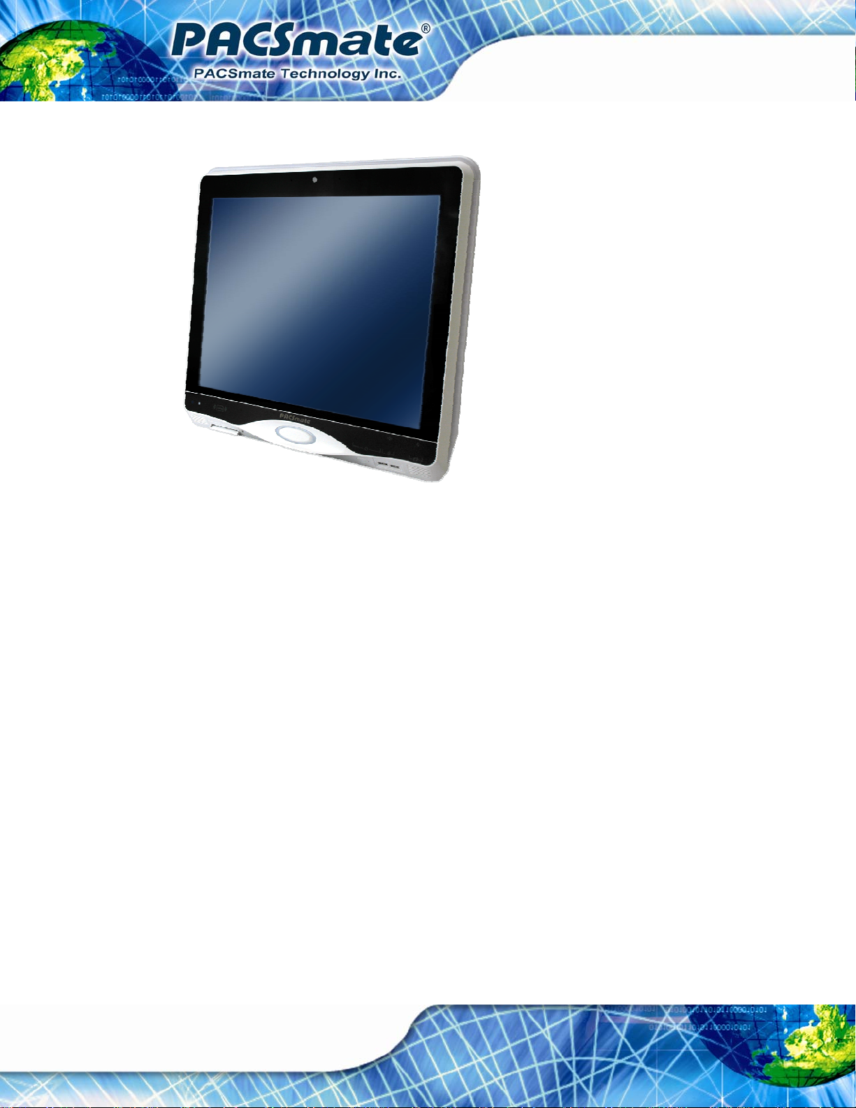
Figure 1-1: IBS-19A Series Medical Panel PC
The IBS-19A Series is an Intel® Core™ powered flat panel PC with a rich variety of
functions and peripherals. All IBS-19A Series models are designed for easy and simplified
integration into point-of-care (POC) applications.
An Intel® Core™ i5/i3 processor coupled with the Intel® H61 chipset delivers optimal
memory, graphics, and peripheral I/O support. The system comes with 2.0 GB of
preinstalled DDR3 dual-channel SO-DIMMs and supports a maximum of 8.0 GB ensuring
smooth data throughputs with reduced bottlenecks and fast system access. Dual display
support is provided via the HDMI port.
Two serial ports and five external USB 2.0 ports provide simplified connectivity to a variety
of external peripheral devices. Wi-Fi capabilities and three RJ-45 GbE connectors allow
for smooth connection of the system to an external LAN. The IBS-19A Series also
supports a 2.5” SATA HDD drive which can be accessed without removing the entire back
Page 16
panel.
Page 17
IBS-19A Series Medical Panel PC
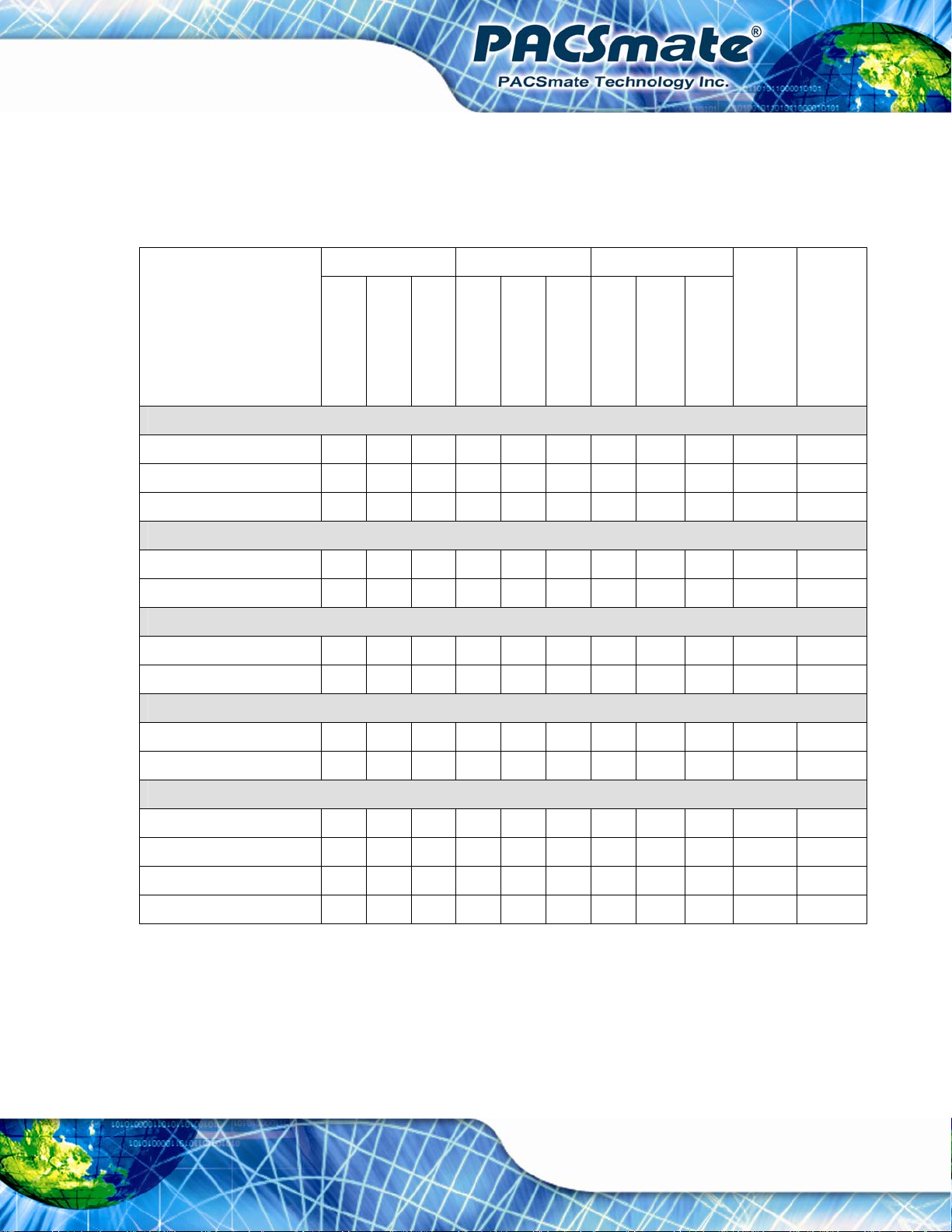
1.2 Model Variations
The IBS-19A Series has 11 models. Each model is preinstalled with one 2GB DDR3
SO-DIMM. The model variations are listed in the table below.
IBS-19A3S- IBS-19A3L- IBS-19A3D-
IBS-19A3P-i5/2G/
32G
i5/2G/32G
i3/2G/25G
G620T/2G/25G
i5/2G/32G
i3/2G/25G
G620T/2G/25G
i5/2G/32G
i3/2G/25G
Intel® CPU
i5-2390T Y Y Y Y Y
i3-2100T Y Y Y
Pentium® G620T Y Y Y
G620T/2G/25G
IBS-19A6P-i5/2G/
32G
HDD
320GB Y Y Y Y Y
250GB Y Y Y Y Y Y
LCD Brightness
300 cd/m2 Y Y Y Y Y Y Y Y Y Y
600 cd/m2 Y
Touchscreen
Resistive Type Y Y Y Y Y Y Y Y Y
Anti-reflection Acrylic Y Y
Others
DICOM GSDF Y Y Y Y Y
LED Dash Light Y Y Y
RFID Y Y Y
Smart Card Reader Y Y Y
Table 1-1: Model Variations
Page 17
Page 18

1.3 Features
The IBS-19A Series features the following:
Intel® Core™ i5/i3 or Pentium® processor
Intel® H61 chipset
2.0 GB DDR3 SO-DIMM preinstalled
802.11 a/b/g/n wireless module
LED dash light design
Five USB 2.0 ports (three on the rear, two on the front)
Watchdog timer that triggers a system reset if the system hangs for some
IP 65 compliant front panel
AT or ATX power mode
5-wire resistive type touch screen
IBS-19A Series Medical Panel PC
reason
Anti-bacteria housing
RoHS compliance
1.4 External Overview
1.4.1 General Description
The stylish IBS-19A Series panel PC is comprised of a screen, rear panel and bottom
panel. An ABS/PC plastic front frame surrounds the front screen. The rear panel provides
screw holes for a wall-mounting bracket compliant with VESA FDMI standard. The I/O
interfaces facing backward and downward on the rear panel provides access to external
interface connectors that include LAN, USB 2.0, serial ports, reset button, HDMI, audio
connectors, power connector, power switch connector and AT/ATX mode switch.
1.4.2 Front Panel
The front side of the IBS-19A Series is a flat panel TFT LCD screen surrounded by an
anti-bacteria plastic frame. The webcam and microphone are located at the top center of
Page 18
the front panel. Two USB 2.0 ports and the optional smart card reader are also located on
the front panel (
The front panel also includes two sensors and two control buttons:
Figure 1-2).
Page 19
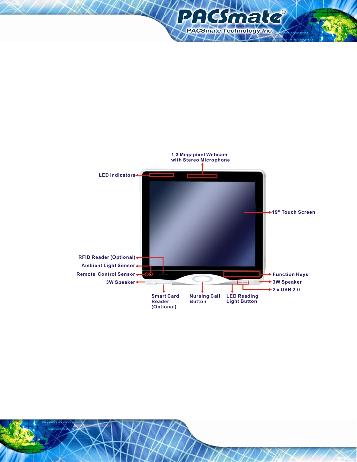
IBS-19A Series Medical Panel PC
Ambient Light Sensor
The ambient light sensor detects the brightness of ambient environment when
the auto-dimming function is turned on.
Remote Control Sensor
The remote control sensor receive infrared signal from the remote control.
Programmable Nursing Call Button
The nursing call button is surrounded by red LED light and is programmable.
LED Reading Light Button
The button cycles through low, medium, medium high and high intensity plus
on/off to control the LED reading light under the nursing call button.
Figure 1-2: Front View
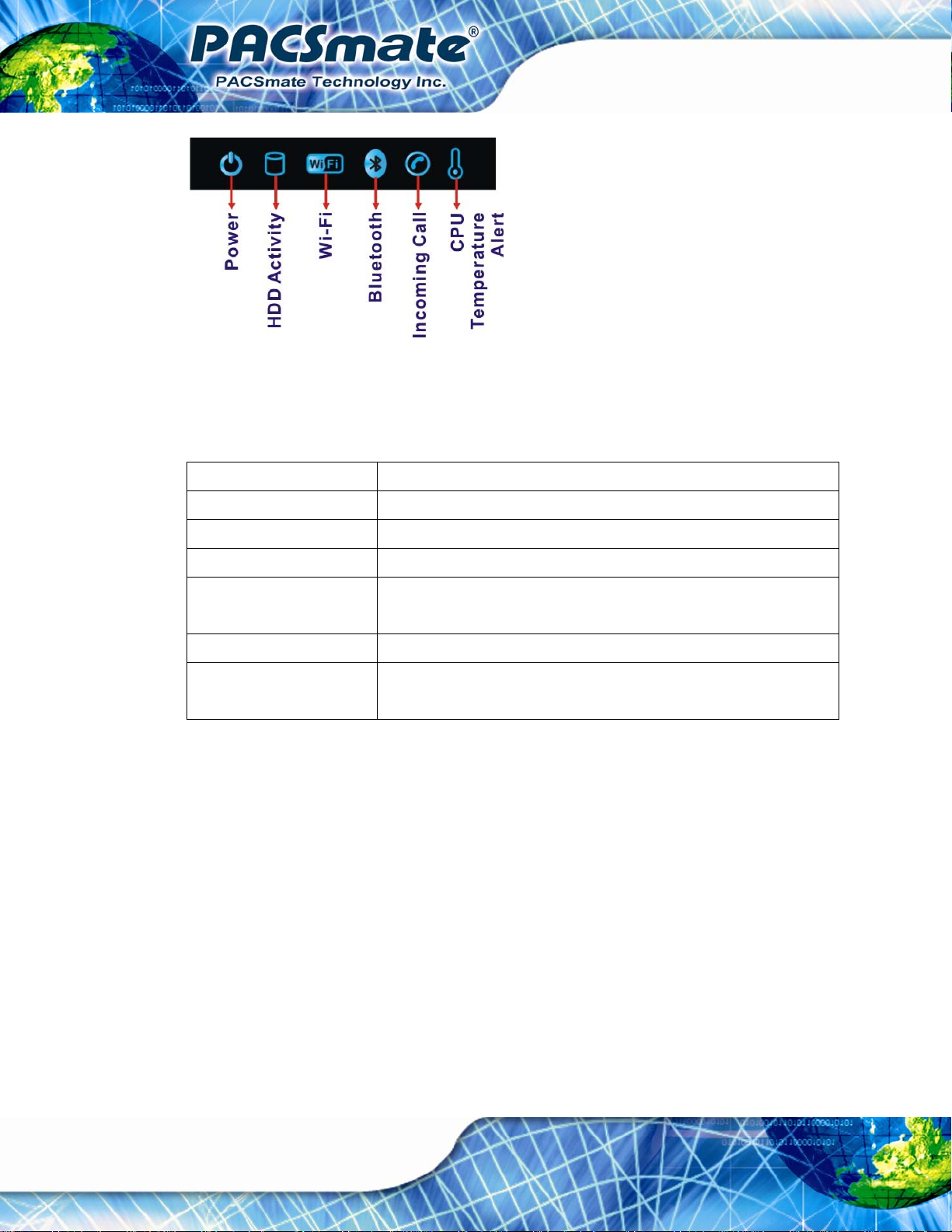
1.4.2.1 LED Indicators
The LED indicators on the front panel of the IBS-19A Series are shown below.
Page 19
Page 20
IBS-19A Series Medical Panel PC
Figure 1-3: LED Indicators
The descriptions of each LED indicator are listed below.
LED Indicator Description
Power Solid Blue: Power on
HDD HDD activity.
Wi-Fi The Wi-Fi connection is enabled or disabled.
Bluetooth The Bluetooth module is enabled or disabled.
Controlled by the BIOS option (see Section
Telephone Blinking blue: incoming call.
CPU Temperature Alert Blue: the CPU temperature is normal.
Red: the CPU temperature is too high.
6.4.2).
Table 1-2: LED Indicators
1.4.2.2 Function Keys
The front panel of the IBS-19A Series contains several function keys that control audio
volume, LCD brightness and some other system components.
Page 20
Page 21
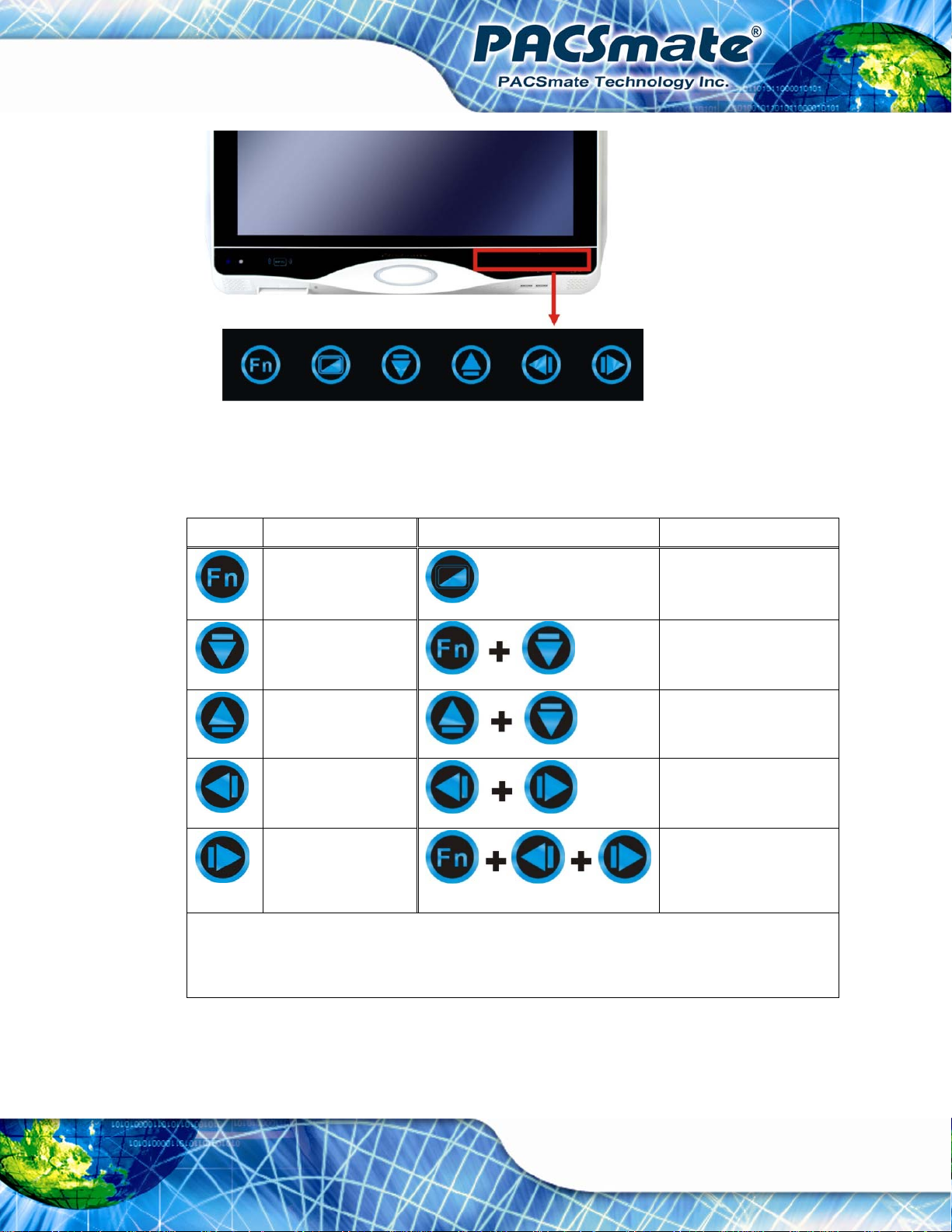
IBS-19A Series Medical Panel PC
Figure 1-4: Function Key Locations
The following table describes the function of these function keys.
Buttons Function Buttons Function
Function
Audio volume down
Audio volume up
Brightness down
Brightness up
Sleep Mode:
After idling for 60 seconds, the function keys go into sleep mode. In sleep mode, the Fn key blinks (on
LCD on/off
Power on/off
(Press for 4 seconds)
Mute audio
Display OSD menu
Lock/Unlock OSD
(Lock: press for 4 secs.
Unlock: press for 7 secs.)
for 1 sec. and off for 4 secs.) while other keys are off. Touch any function key to wake it up.
Table 1-3: Function Keys
Page 21
Page 22
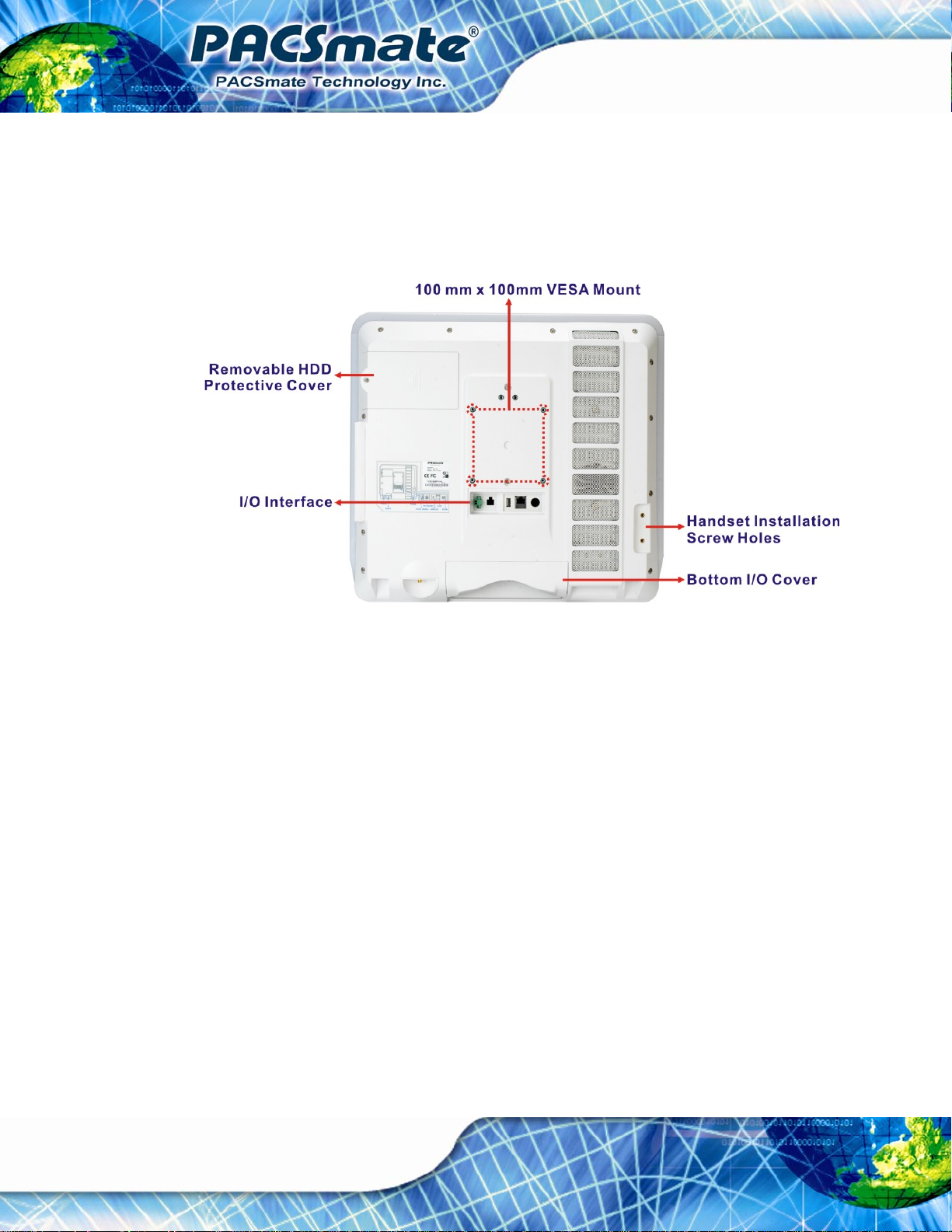
1.4.3 Rear Panel
The rear panel provides access to retention screw holes that support the wall mounting
and the handset installation. A removable HDD and a set of I/O interfaces are also located
IBS-19A Series Medical Panel PC
on the rear panel. Refer to
Figure 1-5: Rear View
1.4.4 I/O Interface Panel
Figure 1-5.
Page 22
The I/O interface panels located on the rear and the bottom of the IBS-19A Series have
the following I/O interface connectors:
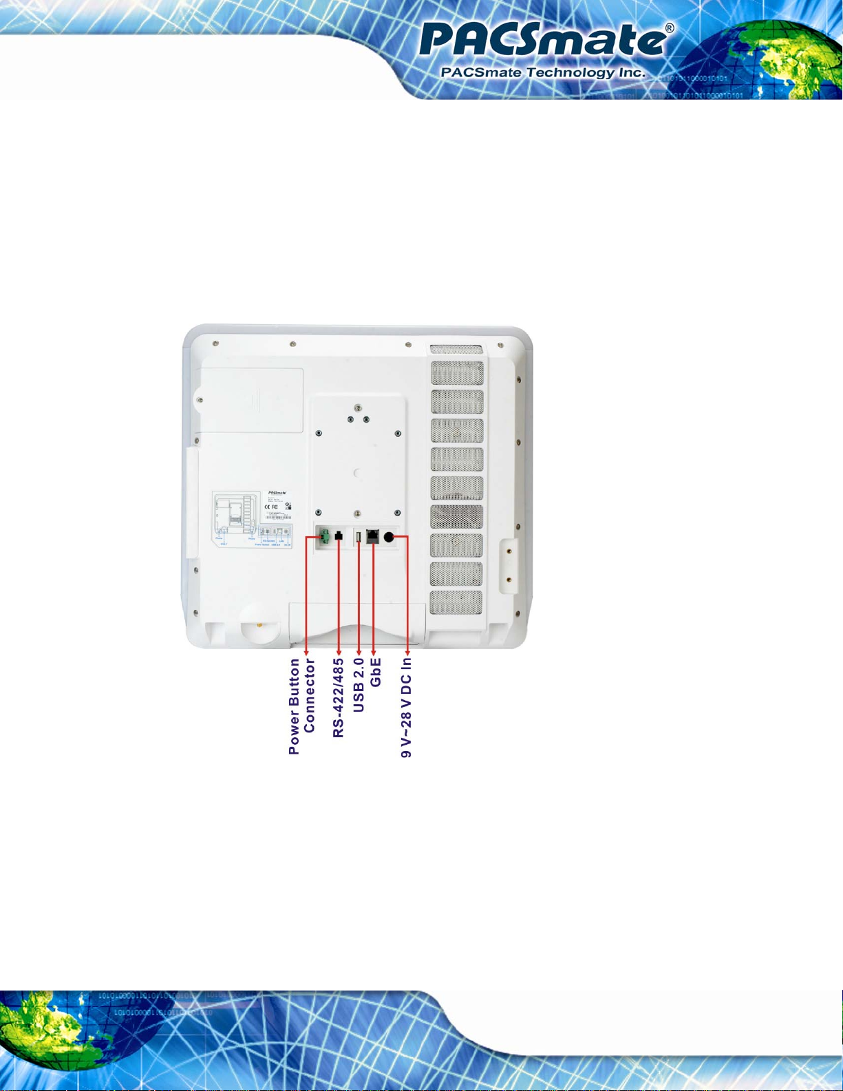
Rear Panel:
o 1 x Power button connector
o 1 x RS-422/485 connector
o 1 x USB 2.0 connector
o 1 x RJ-45 for Giga LAN connectors
o 1 x 9 V ~ 28 V DC In connector
Bottom Panel
o 1 x RS-232 connector
o 1 x HDMI connector
o 2 x RJ-45 for Giga LAN connectors
o 2 x USB 2.0 connectors
Page 23
IBS-19A Series Medical Panel PC
o 1 x Audio mic-in connector
o 1 x Audio line-out connector
o 1 x 9 V ~ 28 V DC In connector
o 1 x Phone jack for handset
o 1 x AT/ATX power mode switch
o 1 x Reset button
The external I/O interface connector panels are shown in
Figure 1-6 and Figure 1-7.
Figure 1-6: I/O Interface Connector Panel (Rear)
Page 23
Page 24
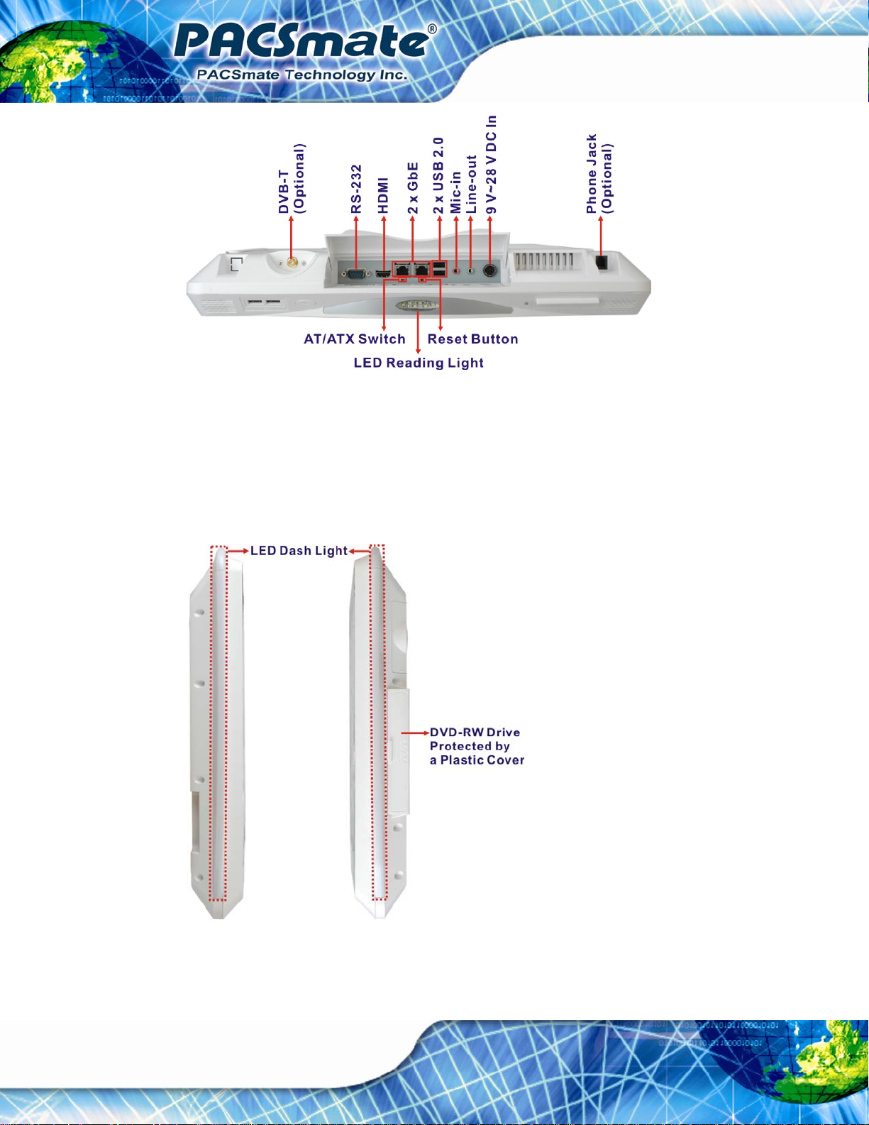
Figure 1-7: I/O Interface Connector Panel (Bottom)
1.4.5 Side Panels
IBS-19A Series Medical Panel PC
The two side panels of the IBS-19A Series contain LED dash lights and a slim DVD-RW
drive protected by a plastic cover. See
Figure 1-8.
Page 24
Figure 1-8: Side View
Page 25
IBS-19A Series Medical Panel PC
1.5 Internal Overview
The IBS-19A Series has the following components installed internally:
Motherboard
2.0 GB 1333 MHz DDR3 SO-DIMM
Wireless module
Bluetooth module
320GB/250GB SATA HDD
Slim DVD-RW drive
1.6 System Specifications
The technical specifications for the IBS-19A Series systems are listed in Table 1-4.
Specification IBS-19A Series
CPU Intel® Pentium® G620T 2.2G CPU
Intel® Core™ i3-2100T 2.5G CPU
Intel® Core™ i5-2390T 2.7G CPU
Chipset Intel® H61
Memory Pentium® G620T:
One 204-pin 2 GB 1333 MHz DDR3 SO-DIMM preinstalled
Core i3/i5:
Two 204-pin 1 GB 1333 MHz DDR3 SO-DIMM preinstalled
(system max. 8GB, dual SO-DIMM slot)
LCD Size 19”
Max. Resolution 1280 x 1024
Contrast Ratio 2000:1
Brightness (cd/m2) 300
Viewing Angle 89/89/89/89
Backlight LED
Backlight MTBF 50,000
Touch Panel 5-wire resistive type
OSD Keys Six OSD keys (LCD on/off, audio up/down, brightness up/down)
One programmable function key
Page 25
Page 26
Specification IBS-19A Series
Gamma Table Grayscale Mode - DICOM GSDF Clear Base 6500K
Grayscale Mode - DICOM GSDF Blue Base 9300K
Color Mode - Gamma 2.2 6500K
Color Mode - DICOM GSDF Clear Base 6500K
Color Mode - Gamma 2.2 9300K
Color Mode - DICOM GSDF Blue Base 9300K
Remote Control Infrared remote control for OSD control
LED Dash Light Upper: 26 x True color LED
Left: 20 x True color LED
Right: 20 x True color LED
Watchdog Timer Software programmable supports 1 sec. ~ 255 sec. system reset
RFID Optional Mifare 13.56Mhz RFID reader
Smart Card Reader Optional ISO7816-1/2/3 card reader
IBS-19A Series Medical Panel PC
Wireless Connection
Wi-Fi Wireless LAN 802.11 a/b/g/n dual-band 2.4Ghz/5Ghz
Bluetooth Bluetooth 2.1 + EDR (internal USB module)
HSDPA Optional 3.5G HSDPA modem
Drive Bays
HDD Drive Bay One 2.5” 320GB/250GB SATA HDD preinstalled
ODD One Slim DVD-RW drive (24x)
Audio/Video
Webcam 1.3-megapixel CMOS Camera (1280 x 1024)
Microphone Stereo microphone
Speaker AMP 3 W + AMP 3 W (built-in stereo speakers)
Handset Optional handset with speaker and MIC
Digital TV Tuner Optional DVB-T and ISDB-T module
I/O Ports and Switches
Rear Panel I/O (Backward) 1 x External power switch connector
1 x RS-422/485 COM port connector
1 x USB 2.0 port
1 x RJ-45 for GbE LAN
Rear Panel I/O (Downward) 1 x RS-232 COM port connector
1 x HDMI port
Page 26
Page 27
IBS-19A Series Medical Panel PC
Specification IBS-19A Series
2 x RJ-45 for GbE LAN
2 x USB 2.0 ports
1 x Audio mic-in connector
1 x Audio line-out connector
1 x Reset button
1 x AT/ATX power mode switch
Front Panel I/O 2 x USB 2.0 ports
Power
Power Input 9 V ~ 28 V DC
Power Adapter
(Medical Grade)
Physical
Mounting Wall, Stand, Arm (VESA 100 mm x 100 mm)
Construction Material Anti-bacteria plastic front frame
Dimensions (mm) (W x H x D) 466 x 428 x 65
Net Weight 7.1kg
Environment
Operation Temperature 0ºC ~ 40ºC
Storage Temperature -20ºC ~ 60ºC
IP Level (Front P anel) IP 65
EMC/Safety UL60601-1, EN60601-1, CE (60601-1-2), FCC class B
120W
Input: 90 VAC ~ 264 VAC @ 50 Hz / 60 Hz
Output: 12 V DC
Table 1-4: System Specifications
Page 27
Page 28
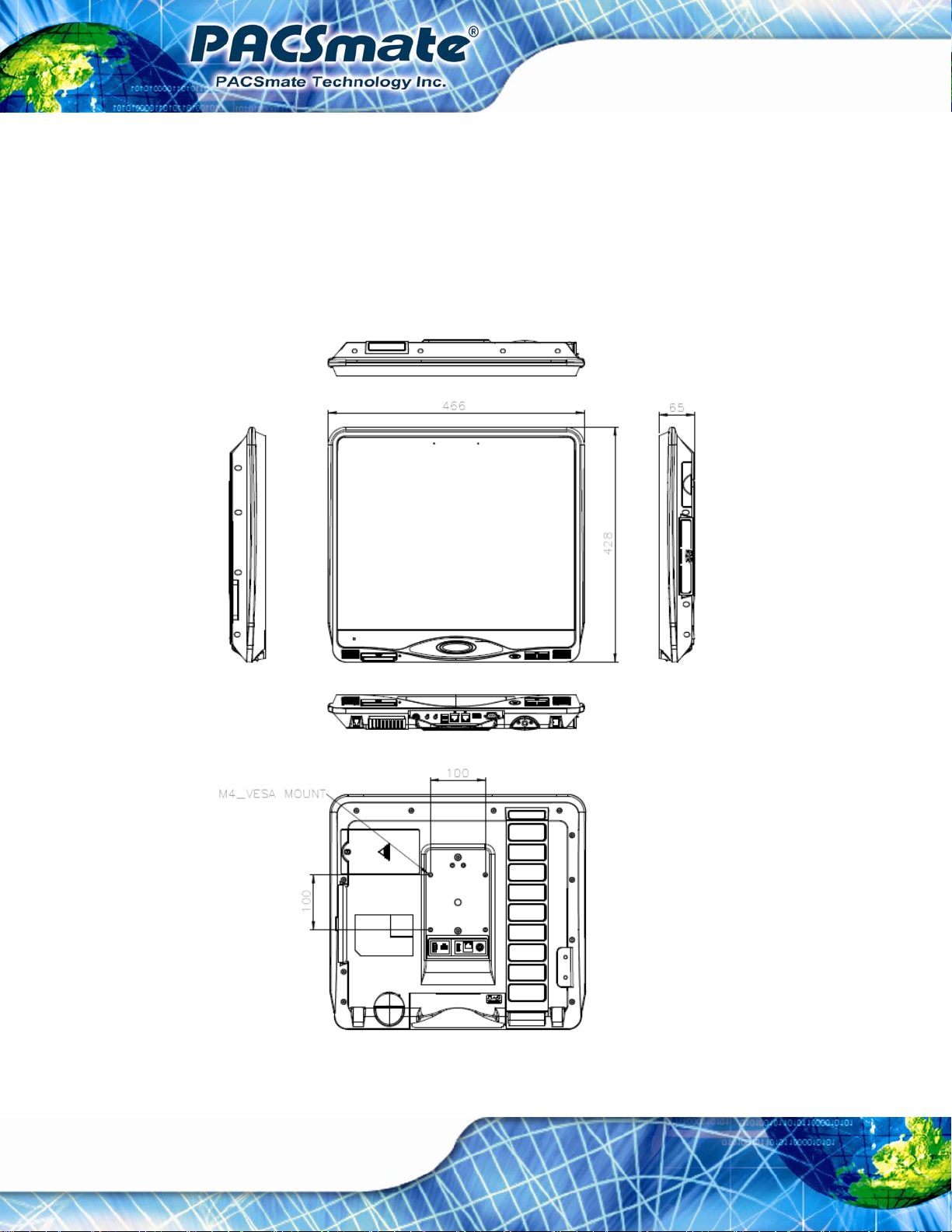
1.7 Dimensions
The IBS-19A Series dimensions are shown in Figure 1-9 and listed below.
Width: 466 mm
Height: 428 mm
Depth: 65 mm
IBS-19A Series Medical Panel PC
Page 28
Figure 1-9: IBS-19A Series Dimensions (mm)
Page 29

IBS-19A Series Medical Panel PC
Chapter
2
2 Unpacking
Page 29
Page 30
2.1 Unpacking
To unpack the flat panel PC, follow the steps below:
WARNING!
The front side LCD screen has a protective plastic cover stuck to the
screen. Only remove the plastic cover after the flat panel PC has been
properly installed. This ensures the screen is protected during the
installation process.
Step 1: Use box cutters, a knife or a sharp pair of scissors that seals the top side of the
external (second) box.
IBS-19A Series Medical Panel PC
Step 2: Open the external (second) box.
Step 3: Use box cutters, a knife or a sharp pair of scissors that seals the top side of the
internal (first) box.
Step 4: Lift the monitor out of the boxes.
Step 5: Remove both polystyrene ends, one from each side.
Step 6: Pull the plastic cover off the flat panel PC.
Step 7: Make sure all the components listed in the packing list are present.
2.2 Packing List
The IBS-19A Series flat panel PC is shipped with the following components:
NOTE:
Page 30
If any of these items are missing or damaged, contact the distributor or
sales representative immediately.
Page 31

IBS-19A Series Medical Panel PC
Quantity Item Image
Standard
1 IBS-19A Series Medical Panel PC
1 Medical-grade power adapter
1 Power cord
1 Remote Control
1 Screw kit
1 User manual CD and driver CD
Page 31
Page 32

IBS-19A Series Medical Panel PC
Chapter
3
3 Installation
Page 32
Page 33

IBS-19A Series Medical Panel PC
3.1 Anti-static Precautions
WARNING:
Failure to take ESD precautions during the maintenance of the device
may result in permanent damage to the device and severe injury to the
user.
Electrostatic discharge (ESD) can cause serious damage to electronic components,
including the IBS-19A Series. Dry climates are especially susceptible to ESD. It is
therefore critical that whenever the IBS-19A Series is accessed internally, or any other
electrical component is handled, the following anti-static precautions are strictly adhered
to.
Wear an anti-static wristband: - Wearing a simple anti-static wristband can
help to prevent ESD from damaging the board.
Self-grounding: - Before handling the board touch any grounded conducting
material. During the time the board is handled, frequently touch any
conducting materials that are connected to the ground.
Use an anti-static pad: - When configuring the IBS-19A Series, place it on an
antic-static pad. This reduces the possibility of ESD damaging the device.
Only handle the edges of the PCB: - When handling the PCB, hold the PCB
by the edges.
3.2 Installation Precautions
When installing the flat panel PC, please follow the precautions listed below:
Power turned off: When installing the flat panel PC, make sure the power is
off. Failing to turn off the power may cause severe injury to the body and/or
damage to the system.
Certified Engineers: Only certified engineers should install and modify
onboard functionalities.
Page 33
Page 34

Anti-static Discharge : If a user open the rear panel of the flat panel PC, to
configure the jumpers or plug in added peripheral devices, ground themselves
first and wear and anti-static wristband.
IBS-19A Series Medical Panel PC
3.3 Installation and Configuration Steps
The following installation steps must be followed.
Step 1: Install the handset (optional)
Step 2: Connect peripheral devices to the bottom panel of the flat panel PC
Step 3: Mount the flat panel PC
3.4 Handset Installation (Optional)
An optional handset can be installed on the IBS-19A Series to make VOIP call. To install
the handset, please follow the steps below.
Step 1: Locate the two retention screw holes on the rear panel.
Step 2: Secure the handset base with the IBS-19A Series by two retention screws
Figure 3-1).
(
Page 34
Figure 3-1: Handset Base Installation
Page 35

IBS-19A Series Medical Panel PC
Step 3: Plug the handset cord into the phone jack on the bottom panel (Figure 3-2).
Figure 3-2: Handset Connection
Step 4: Place the handset in the base (
Figure 3-3: Place the Handset
Figure 3-3).
Page 35
Page 36

3.5 I/O Panel Connectors
The bottom panel and rear panel of the IBS-19A Series contain I/O connectors, switches
IBS-19A Series Medical Panel PC
and a reset button. These connector locations can be found in Section
descriptions of the connectors and cabling can be found in the subsections below.
1.4.4. Detailed
3.5.1 Access the Bottom I/O Interface
The I/O interface on the bottom panel is protected by a plastic cover. To access the I/O
interface, follow the steps below to open the cover.
Step 1: Pull the cover downward as shown in
Figure 3-4.
Page 36
Figure 3-4: Pull Down the I/O Cover
Step 2: Open the cover as shown in
Figure 3-5.
Page 37

IBS-19A Series Medical Panel PC
Figure 3-5: Open the I/O Cover
3.5.2 Audio Connectors
The audio jacks connect to external audio devices.
Microphone (Pink): Connects a microphone.
Line Out port (Green): Connects to a headphone or a speaker. With
multi-channel configurations, this port can also connect to front speakers.
3.5.3 HDMI Connector
The HDMI connector can connect to an HDMI device. The pinouts of the HDMI connector
are shown below.
Pin Description Pin Description
1 HDMI_DATA2 2 GND
3 HDMI_DATA2# 4 HDMI_DATA1
5 GND 6 HDMI_DATA1#
7 HDMI_DATA0 8 GND
9 HDMI_DATA0# 10 HDMI_CLK
Page 37
Page 38

Pin Description Pin Description
11 GND 12 HDMI_CLK#
13 N/C 14 N/C
15 HDMI_SCL 16 HDMI_SDATA
17 GND 18 +5V
19 HDMI_HPD 20 HDMI_GND
21 HDMI_GND 22 HDMI_GND
23 HDMI_GND
IBS-19A Series Medical Panel PC
Table 3-1: HDMI Connector Pinouts
Figure 3-6: HDMI Connector
To connect the HDMI cable to the IBS-19A Series, follow the steps below.
Step 1: Locate the HDMI connector. The location is shown in Section
1.4.4.
Step 2: Align the connector. Align the HDMI connector with the HDMI port. Make sure
the orientation of the connector is correct.
Page 38
Figure 3-7: HDMI Connection
Page 39

IBS-19A Series Medical Panel PC
Step 3: Insert the HDMI connector. Gently insert the HDMI connector. The connector
should engage with a gentle push. If the connector does not insert easily, check
again that the connector is aligned correctly, and that the connector is being
inserted with the right way up.
3.5.4 LAN Connectors
The LAN connector allows connection to an external network. The pinouts of the RJ-45
LAN connector are shown below.
Pin Description Pin Description
1 MDI0+ 10 MDI32 MDI0- 11 +3.3Vsus
3 MDI1+ 12 ACT-1
4 MDI1- 13 Link 1000, +3.3Vsus
5 N/A 14 Link 100, +3.3Vsus
6 N/A 15 GND
7 MDI2+ 16 GND
8 MDI2- 17 N/A
9 MDI3+ 18 N/A
Table 3-2: LAN Pinouts
Figure 3-8: RJ-45 Ethernet Connector
The RJ-45 Ethernet connector has two status LEDs, one green and one yellow. See
Figure 3-8.
Page 39
Page 40

LED Description LED Description
IBS-19A Series Medical Panel PC
A on: linked
blinking: data is being sent/received
B off: 10 Mb/s
green: 100 Mb/s
orange: 1000 Mb/s
Table 3-3: RJ-45 Ethernet Connector LEDs
To connect the IBS-19A Series to a network through the RJ-45 LAN connector, follow the
steps below.
Step 1: Locate the RJ-45 connector. The location of the RJ-45 connectors is shown in
Section
1.4.4.
Step 2: Align the connectors. Align the RJ-45 connector on the LAN cable with one of
the RJ-45 connectors on the IBS-19A Series. See
Figure 3-9.
Figure 3-9: LAN Connection
Step 3: Insert the LAN cable RJ-45 connector. Once aligned, gently insert the LAN
cable RJ-45 connector into the on-board RJ-45 connector.
Page 40
Page 41

IBS-19A Series Medical Panel PC
3.5.5 Power Input Connector
The power connector connects to the 9 V ~ 28 V DC power adapter.
Figure 3-10: Power Connector Pinouts
3.5.6 Power Button Connector
The power button connector provides users an option to connect to an external power
button to control system power. However, the user can easily turn the system power on or
off by pressing the function buttons (
Figure 3-11: Power Button Connector Pinouts
) on the front panel (see Section 1.4.2.2).
3.5.7 RS-422/485 Serial Port
A RS-422/485 serial port device can be connected to the RS-422/485 serial port on the
rear panel. The pinouts of the RS-422/485 serial port is shown below.
Figure 3-12: RS-422/485 Serial Port
Page 41
Page 42

Pin Description Pin Description
1 RS-422 TX+ 3 RS-422 RX+ (RS-485 D+)
2 RS-422 TX- 4 RS-422 RX- (RS-485 D-)
IBS-19A Series Medical Panel PC
Table 3-4: RS-422/485 Serial Port Pinouts
To install the RS-422/485 devices, follow the steps below.
Step 1: Locate the RS-422/RS485 connector. The location of the RS-422/RS-485
connector is shown in Section
1.4.4.
Step 2: Connect the RS-422/485 connector to the RS-422/485 cable.
Step 3: Insert the serial connector. Insert the DB-9 connector of a serial device into
the DB-9 connector on the RS-422/485 cable.
Step 4: Secure the connector. Secure the serial device connector to the external
interface by tightening the two retention screws on either side of the connector.
Step 5: The DB-9 connector pinouts are listed below.
Page 42
Figure 3-13: RS-422/485 Serial Port (DB-9)
Pin RS-422 RS-485
1 TX+ -2 TX- -3 RX+ DATA+
4 RX- DATA-
Page 43

IBS-19A Series Medical Panel PC
Pin RS-422 RS-485
5 -- -6 -- -7 -- -8 -- -9 -- --
Table 3-5: DB-9 RS-422/485 Serial Port Pinouts
3.5.8 RS-232 Serial Port
A RS-232 serial port device can be connected to the DB-9 RS-232 serial port on the
bottom panel. The pinouts of the DB-9 RS-232 serial port is shown below.
Figure 3-14: DB-9 RS-232 Serial Port
Pin Description Pin Description
1 NDCD1 6 NDSR1
2 NRXD1 7 NRTS1
3. NTX1 8 NCTS1
4. NDTR1 9 COM_RI1
5 GND
Table 3-6: DB-9 RS-232 Serial Port Pinouts
To install the RS-232 devices, follow the steps below.
Step 1: Locate the DB-9 connector. The location of the DB-9 connector is shown in
Section
1.4.4.
Page 43
Page 44

Step 2: Insert the serial connector. Insert the DB-9 connector of a serial device into
IBS-19A Series Medical Panel PC
the DB-9 connector on the bottom panel. See
Figure 3-15: Serial Device Connector
Figure 3-15.
Step 3: Secure the connector. Secure the serial device connector to the external
interface by tightening the two retention screws on either side of the connector.
3.5.9 USB Connectors
The USB ports are for attaching USB peripheral devices to the system. The pinouts of the
USB port is shown below.
Pin Description Pin Description
1 VCC 5 VCC
2 DATA- 6 DATA3 DATA+ 7 DATA+
4 GROUND 8 GROUND
Table 3-7: USB Port Pinouts
To install a USB device, follow the steps below.
Page 44
Page 45

IBS-19A Series Medical Panel PC
Step 1: Located the USB connectors. The locations of the USB connectors are shown
in Section
Step 2: Align the connectors. Align the USB device connector with one of the
connectors on the bottom panel. See
1.4.4.
Figure 3-16.
Figure 3-16: USB Device Connection
Step 3: Insert the device connector. Once aligned, gently insert the USB device
connector into the onboard connector.
3.6 AT/ATX Mode Selection
AT and ATX power modes can both be used on the IBS-19A Series. The selection is
made through an AT/ATX switch on bottom panel (
ATX mode, follow the steps below.
Step 1: Locate the AT/ATX switch on the bottom panel (
Figure 3-17). To select AT mode or
Figure 3-17).
Page 45
Page 46

Figure 3-17: AT/ATX Switch Location
Step 2: Adjust the switch according to the preferred setting.
3.6.1 AT Power Mode
With the AT mode selected, the power is controlled by a central power unit rather than a
power switch. The IBS-19A Series panel PC turns on automatically when the power is
connected.
IBS-19A Series Medical Panel PC
3.6.2 ATX Power Mode
With the ATX mode selected, the IBS-19A Series panel PC goes in a standby mode when
it is turned off. The panel PC can be easily turned on via network or a power switch in
standby mode.
3.7 Mounting the System
WARNING!
When mounting the flat panel PC onto an arm, onto the wall or onto a
panel, it is better to have more than one person to help with the installation
to make sure the panel PC does not fall down and get damaged.
The four methods of mounting the IBS-19A Series are listed below.
Arm mounting
Page 46
Stand mounting
Wall mounting
The four mounting methods are described below.
Page 47

IBS-19A Series Medical Panel PC
3.7.1 Arm Mounting
The IBS-19A Series is VESA (Video Electronics Standards Association) compliant and
can be mounted on an arm with a 100 mm interface pad. To mount the IBS-19A Series on
an arm, please follow the steps below.
Step 1: The arm is a separately purchased item. Please correctly mount the arm onto
the surface it uses as a base. To do this, refer to the installation documentation
that came with the mounting arm.
NOTE:
When purchasing the arm please ensure that it is VESA compliant and
that the arm has a 100 mm interface pad. If the mounting arm is not
VESA compliant it cannot be used to support the IBS-19A Series.
Step 2: Once the mounting arm has been firmly attached to its surface, lift the IBS-19A
Series onto the interface pad of the mounting arm.
Step 3: Align the retention screw holes on the mounting arm interface with those in the
IBS-19A Series. The IBS-19A Series arm mount retention screw holes are
shown in
Figure 3-18.
Page 47
Page 48

Figure 3-18: Arm Mount Retention Screw Holes
IBS-19A Series Medical Panel PC
Step 4: Secure the IBS-19A Series to the interface pad by inserting four retention
screws through the mounting arm interface pad and into the IBS-19A Series.
Page 48
Figure 3-19: Arm Mounting
Page 49

IBS-19A Series Medical Panel PC
3.7.2 Stand Mounting
To mount the IBS-19A Series using the stand mounting kit, please follow the steps below.
Step 1: Locate the screw holes on the rear of the IBS-19A Series. This is where the
bracket will be attached.
Step 2: Align the bracket with the screw holes.
Step 3: To secure the bracket to the IBS-19A Series insert the retention screws into the
screw holes and tighten them.Step 3:
Figure 3-20: Stand Mounting
3.7.3 Wall Mounting
To mount the flat panel PC onto the wall, please follow the steps below.
Step 4: Select the location on the wall for the wall-mounting bracket.
Step 5: Carefully mark the locations of the four screw holes in the bracket on the wall.
Step 6: Drill four pilot holes at the marked locations on the wall for the bracket retention
screws.
Page 49
Page 50

Step 7: Align the wall-mounting bracket screw holes with the pilot holes.
Step 8: Secure the mounting-bracket to the wall by inserting the retention screws into
IBS-19A Series Medical Panel PC
the four pilot holes and tightening them (
Figure 3-21).
Figure 3-21: Wall-mounting Bracket
Step 9: Insert the four monitor mounting screws provided in the wall mounting kit into the
four screw holes on the real panel of the flat panel PC and tighten until the screw
shank is secured against the rear panel (
Step 10: Align the mounting screws on the monitor rear panel with the mounting holes on
the bracket.
Step 11: Carefully insert the screws through the holes and gently pull the monitor
downwards until the monitor rests securely in the slotted holes (
Ensure that all four of the mounting screws fit snuggly into their respective
slotted holes.
Figure 3-22).
Figure 3-22).
NOTE:
In the diagram below the bracket is already installed on the wall.
Page 50
Page 51

IBS-19A Series Medical Panel PC
Figure 3-22: Chassis Support Screws
Step 12: Secure the panel PC by fastening the retention screw of the wall-mounting
bracket. (
Figure 3-23).
Page 51
Page 52

IBS-19A Series Medical Panel PC
Figure 3-23: Securing the Panel PC
3.8 Remote Control
The IBS-19A Series comes with a remote control for easy configuration. 6Figure 3-24
shows the remote control and its function keys.
Page 52
Figure 3-24: Remote Control
Page 53

IBS-19A Series Medical Panel PC
System On/Off: Press this button to turn the IBS-19A Series on or off.
LCD On/Off. Press this button to turn the LCD monitor on or off.
Auto-Dimming. Press this button to turn the auto-dimming function on or off.
Brightness. Use these control buttons to adjust the brightness of the LCD
screen.
Volume. Press these buttons to adjust the audio volume level.
Page 53
Page 54

IBS-19A Series Medical Panel PC
Chapter
4
4 OSD Controls
Page 54
Page 55

IBS-19A Series Medical Panel PC
4.1 User Mode OSD Structure
4.1.1 OSD Control Keys
The on-screen-display (OSD) is controlled by two of the function keys on the front panel –
left key and right key. See
Figure 4-1.
Figure 4-1: OSD Control Keys
The following table describes the function of these two OSD control keys.
Buttons Function
Press these two keys at the same time to:
1. Open the OSD window.
2. Confirm the selection of th e item inside a menu.
3. Confirm the function adjustment.
Press this key to scroll to the left, to decrease the value, or to switch
from one selected item to another.
Press this key to scroll to the right, to increase the value, or to switch
from one selected item to another.
Table 4-1: OSD Control Key Functions
Page 55
Page 56

4.1.2 OSD Menu Structure
Table 4-2 shows the OSD menu structure for all models of the IBS-19A Series.
Level 0 Level 1 Value
IBS-19A Series Medical Panel PC
Main Display Features Menu
Color Menu Red RGB values from 0 to 100
Green RGB values from 0 to 100
Blue RGB values from 0 to 100
OSD Menu
Brightness 0 to 100
Contrast 0 to 100
Clock 0 to 100
Phase 0 to 100
H. Position 0 to 100
V. Position 0 to 100
Sharpness 1 to 5
OSD Time Out 0 to 60 sec
OSD Position 1 to 5
OSD Transparency 20, 40, 60, 80, 100
Factory Reset Select
Auto Adjust Select
Auto Color Select
Auto Dimming Off or On
Exit Menu Exit Select
Table 4-2: OSD Menus
Page 56
Page 57

IBS-19A Series Medical Panel PC
4.2 Using the OSD
OSD menu options are described below.
4.2.1 Main Display Features
Main display features are shown in Figure 4-2.
Figure 4-2: Main Display Features
The brightness option adjusts the brightness of screen. This function
Brightness
Contrast
Clock
Phase
H. Position
V. Position
Sharpness
adjusts the offset value of ADC. Setting this value too high or too low
will affect the quality of image. When the auto- dimming function is
turned on, the brightness control is not effective.
This function adjusts the gain value of ADC. Adjusting this value too
high or too low will worsen the quality of image.
Adjusts the width of the display screen.
Adjusts the input signal.
Adjusts the horizontal position of the display screen.
Adjusts the vertical position of the display screen
Adjust the sharpness of the display
Page 57
Page 58

4.2.2 Color
Color options are shown in Figure 4-3.
IBS-19A Series Medical Panel PC
Figure 4-3: Color Options
The Color menu fine-tunes the palette of color hues for the LCD.
This item allows fine-tuning the balance among Red, Green, and Blue color
User
hues if images look garish or unrealistic.
4.2.3 OSD Configurations
The OSD configurations are shown in Figure 4-4.
Page 58
Page 59

IBS-19A Series Medical Panel PC
Figure 4-4: OSD Configurations Menu
OSD Configurations are described below.
OSD Time Out
OSD Position
OSD Transparency
Factory Reset
Auto Adjust
Auto Color
Auto Dimming
Determines how many seconds the OSD screen stays on screen
before it disappears when OSD is left unattended.
Adjusts the OSD position on the screen. Position 1 is in the upper left
of the screen, position 2 in the upper right, position 3 in the center,
position 4 in the bottom left and position 5 in the bottom right.
Adjust the transparency of the OSD menu background.
Restores the default OSD settings. Note that this will restore all
default display settings.
Automatically adjusts the position of the display screen
Automatically adjusts the color settings.
Turn on or turn off auto-dimming function. When auto-dimming is
turned on, the monitor automatically adjusts the brightness according
to ambient light conditions.
Page 59
Page 60

IBS-19A Series Medical Panel PC
Chapter
5
5 System Maintenance
Page 60
Page 61

IBS-19A Series Medical Panel PC
5.1 System Maintenance Introduction
A user cannot replace the motherboard, memory modules or other internal components. If
the internal components fail, it must be shipped back to PACSmate to be replaced. If the
internal system components have failed, please contact the system vendor, reseller or a
PACSmate sales person directly.
If the HDD of the IBS-19A Series fail, it must be replaced. The HDD replacement
instructions are described below.
5.2 Anti-static Precautions
WARNING:
Failure to take ESD precautions during the maintenance of the
IBS-19A Series may result in permanent damage to the IBS-19A
Series and severe injury to the user.
Electrostatic discharge (ESD) can cause serious damage to electronic components,
including the IBS-19A Series. Dry climates are especially susceptible to ESD. It is
therefore critical that whenever the panel PC is accessed internally, or any other electrical
component is handled, the following anti-static precautions are strictly adhered to.
Wear an anti-static wristband: - Wearing a simple anti-static wristband can
help to prevent ESD from damaging the board.
Self-grounding: - Before handling the board touch any grounded conducting
material. During the time the board is handled, frequently touch any
conducting materials that are connected to the ground.
Use an anti-static pad: - When configuring the IBS-19A Series, place it on an
antic-static pad. This reduces the possibility of ESD damaging the IBS-19A
Series.
Only handle the edges of the PCB: - When handling the PCB, hold the PCB
by the edges.
Page 61
Page 62

5.3 Turn off the Power
WARNING:
Failing to turn off the system before opening it can cause permanent
damage to the system and serious or fatal injury to the user.
Before any maintenance procedures are carried out on the system, make sure the system
is turned off.
5.4 HDD Replacement
The IBS-19A Series is preinstalled with one HDD. To replace the HDD, follow the
IBS-19A Series Medical Panel PC
instructions below.
Step 1: Follow all anti-static procedures. See Section
Step 2: Turn off the power. See Section
Step 3: Remove the HDD cover by removing the HDD cover retention screw (
5-1).
5.3.
5.2.
Figure
Page 62
Figure 5-1: HDD Cover Retention Screw
Page 63

IBS-19A Series Medical Panel PC
Step 4: Remove the old HDD from the HDD slot (Figure 5-2).
Figure 5-2: HDD Removal
Step 5: Line up the new HDD with the SATA connector.
Step 6: Insert the HDD into SATA connector until it is securely in place.
Step 7: Replace the HDD cover and secure using one (1) retention screw.
Page 63
Page 64

IBS-19A Series Medical Panel PC
Chapter
6
6 BIOS Setup
Page 64
Page 65

IBS-19A Series Medical Panel PC
6.1 Introduction
A licensed copy of the BIOS is preprogrammed into the ROM BIOS. The BIOS setup
program allows users to modify the basic system configuration. This chapter describes
how to access the BIOS setup program and the configuration options that may be
changed.
6.1.1 Starting Setup
The UEFI BIOS is activated when the computer is turned on. The setup program can be
activated in one of two ways.
1. Press the D
2. Press the D
appears on the screen. 0.
If the message disappears before the D
and try again.
ELETE or F2 key as soon as the system is turned on or
ELETE or F2 key when the “Press Del to enter SETUP” message
ELETE or F2 key is pressed, restart the computer
6.1.2 Using Setup
Use the arrow keys to highlight items, press ENTER to select, use the PageUp and
PageDown keys to change entries, press F1 for help and press E
keys are shown in the following table.
Key Function
Up arrow Move to the item above
Down arrow Move to the item below
Left arrow Move to the page on the left hand side
SC to quit. Navigation
Right arrow Move to the page on the right hand side
+ Increase the numeric value or make changes
- Decrease the numeric value or make changes
Esc key Main Menu – Quit and do not save changes into CMOS
Status Page Setup Menu and Option Page Setup Menu --
Exit current page and return to Main Menu
Page 65
Page 66

F1 key General help, only for Status Page Setup Menu and Option
F2 key Load previous values
F3 key Load optimized defaults
F4 key Save changes and Exit BIOS
Table 6-1: BIOS Navigation Keys
6.1.3 Getting Help
When F1 is pressed a small help window describing the appropriate keys to use and the
IBS-19A Series Medical Panel PC
Page Setup Menu
possible selections for the highlighted item appears. To exit the Help Window press E
the F1 key again.
6.1.4 BIOS Menu Bar
The menu bar on top of the BIOS screen has the following main items:
Main Changes the basic system configuration.
Advanced Changes the advanced system settings.
Chipset Changes the chipset settings
Boot Changes the system boot configuration.
Security Sets User and Supervisor Passwords.
Save & Exit Selects exit options and loads default settings
The following sections completely describe the configuration options found in the menu
items at the top of the BIOS screen and listed above.
SC or
Page 66
Page 67

IBS-19A Series Medical Panel PC
6.2 Main
The Main BIOS menu (6BIOS Menu 1) appears when the BIOS Setup program is entered.
The Main menu gives an overview of the basic system information.
Aptio Setup Utility – Copyright (C) 2010 American Megatrends, Inc.
Main Advanced Chipset Boot Security Save & Exit
BIOS Information
BIOS Vendor American Megatrends
Core Version 4.6.4.0 0.15
Compliency UEFI 2.1
Project Version E396AT12.ROM
Build Date and Time 08/22/2012 16:14:47
iWDD Vendor ICP
iWDD Version E396ER11.bin
System Date [Wed 10/01/2012]
System Time [14:27:27]
Access Level Administrator
Version 2.10.1208. Copyright (C) 2010 American Megatrends, Inc.
Set the Date. Use Tab to
switch between Date
elements.
----------------------
ÅÆ
: Select Screen
↑ ↓: Select Item
Enter Select
+/-: Change Opt.
F1: General Help
F2: Previous Values
F3: Optimized Defaults
F4: Save & Exit
ESC: Exit
BIOS Menu 1: Main
System Overview
The System Overvie w lists a brief summary of different system components. The fields in
System Overview cannot be changed. The items shown in the system overview include:
BIOS Vendor: Installed BIOS vendor
Core Version: Current BIOS version
Compliency: Compliant BIOS specification
Project Version: The board version
Build Date and Time: Date and time the current BIOS version was made
The System Overview field also has two user configurable fields:
System Date [xx/xx/xx]
Use the System Date option to set the system date. Manually enter the day, month and
year.
Page 67
Page 68

System Time [xx:xx:xx]
Use the System Time option to set the system time. Manually enter the hours, minutes
and seconds.
6.3 Advanced
Use the Advanced menu (6BIOS Menu 2) to configure the CPU and peripheral devices
through the following sub-menus:
WARNING:
Setting the wrong values in the sections below may cause the system
to malfunction. Make sure that the settings made are compatible with
the hardware.
IBS-19A Series Medical Panel PC
ACPI Settings
CPU Configuration
SATA Configuration
USB Configuration
Super IO Configuration
H/W Monitor
Serial Port Console Redirection
Page 68
Page 69

S
IBS-19A Series Medical Panel PC
Aptio Setup Utility – Copyright (C) 2010 American Megatrends, Inc.
Main Advanced Chipset Boot Security Save & Exit
> ACPI Settings
> CPU Configuration
> SATA Configuration
> USB Configuration
> Super IO Configuration
> H/M Monitor
> Serial Port Console Redirection
Version 2.10.1208. Copyright (C) 2010 American Megatrends, Inc.
BIOS Menu 2: Advanced
System ACPI Parameters
----------------------
ÅÆ
↑ ↓: Select Item
Enter Select
+/-: Change Opt.
F1: General Help
F2: Previous Values
F3: Optimized Defaults
F4: Save & Exit
ESC: Exit
: Select Screen
6.3.1 ACPI Settings
The ACPI Settings menu (6BIOS Menu 4) configures the Advanced Configuration and
Power Interface (ACPI) options.
Aptio Setup Utility – Copyright (C) 2010 American Megatrends, Inc.
Advanced
ACPI Settings
ACPI Sleep State [S1 (CPU Stop Clock)]
Version 2.10.1208. Copyright (C) 2010 American Megatrends, Inc.
elect the highest ACPI
sleep state the system
will enter, when the
SUSPEND button is
pressed.
----------------------
ÅÆ
: Select Screen
↑ ↓: Select Item
Enter Select
+/-: Change Opt.
F1: General Help
F2: Previous Values
F3: Optimized Defaults
F4: Save & Exit
ESC: Exit
BIOS Menu 3: ACPI Settings
Page 69
Page 70

ACPI Sleep State [S1 (CPU Stop Clock)]
Use the ACPI Sleep State option to specify the sleep state the system enters when it is
not being used.
IBS-19A Series Medical Panel PC
Î
S1 (CPU Stop
Clock)
Î
S3 (Suspend to
RAM)
DEFAULT
The system enters S1 (POS) sleep state. The
system appears off. The CPU is stopped; RAM is
refreshed; the system is running in a low power
mode.
The caches are flushed and the CPU is powered
off. Power to the RAM is maintained. The
computer returns slower to a working state, but
more power is saved.
6.3.2 CPU Configuration
Use the CPU Configuration menu (BIOS Menu 4) to view detailed CPU specifications
and configure the CPU.
Page 70
Page 71

o
IBS-19A Series Medical Panel PC
Aptio Setup Utility – Copyright (C) 2010 American Megatrends, Inc.
Advanced
CPU Configuration
Intel(R) Core(TM) i5-2390T CPU @ 2.70GHz
Processor Stepping 206a7
Microcode Revision 17
Max Processor Speed 2700 MHz
Min Processor Speed 1600 MHz
Processor Speed 2700 MHz
Processor Cores 2
Intel HT Technology Supported
EMT64 Supported
Hyper-threading [Enabled]
Intel Virtualization Technology [Disabled]
Version 2.10.1208. Copyright (C) 2010 American Megatrends, Inc.
Enabled for Windows XP and
Linux (OS optimized for
Hyper-Threading
Technology) and Disabled
for other OS (OS not
optimized for
Hyper-Threading
Technology). When Disabled
nly one thread per enabled
core is enabled.
----------------------
ÅÆ
: Select Screen
↑ ↓: Select Item
Enter Select
+/-: Change Opt.
F1: General Help
F2: Previous Values
F3: Optimized Defaults
F4: Save & Exit
ESC: Exit
BIOS Menu 4: CPU Configuration
The CPU Configuration menu (
Processor Type: Lists the brand name of the CPU being used
Processor Stepping: Lists the CPU processing stepping
Microcode Revision: Lists the microcode revision
Max processor Speed: Lists the CPU max. processing speed
Min processor Speed: Lists the CPU min. processing speed
Processor Speed: Lists the CPU processing speed
Processor Cores: Lists the number of the processor core
Intel HT Technology: Indicates if Intel HT Technology is supported by the
CPU.
EMT64: Indicates if EM64T is supported by the CPU.
Hyper-threading [Enabled]
Use the Hyper Threading option to enable or disable the CPU hyper threading function.
BIOS Menu 4) lists the following CPU details:
Page 71
Page 72

IBS-19A Series Medical Panel PC
Î
Disabled
Î
Enabled DEFAULT
Intel® Virtualization Technology [Disabled]
Use the Intel® Virtualization Technology option to enable or disable virtualization on the
system. When combined with third party software, Intel Virtualization technology allows
several OSs to run on the same system at the same time.
Î
Disabled DEFAULT
Î
Enabled
Disables the use of hyper threading technology
Enables the use of hyper threading technology
Disables Intel Virtualization Technology.
Enables Intel Virtualization Technology.
6.3.3 SATA Configuration
Use the SATA Configuration menu (BIOS Menu 5) to change and/or set the
configuration of the SATA devices installed in the system.
Aptio Setup Utility – Copyright (C) 2010 American Megatrends, Inc.
Advanced
SATA Mode Selection [IDE]
Serial ATA Port 0 TOSHIBA MK3267 (320.0
Software Preserve SUPPORTED
Serial ATA Port 1 TEAC DV-W28 ATAPI
Software Preserve N/A
Version 2.10.1208. Copyright (C) 2010 American Megatrends, Inc.
BIOS Menu 5: SATA Configuration
SATA Mode Selection [IDE]
Determines how SATA
controller(S) operate.
---------------------
ÅÆ
: Select Screen
↑ ↓: Select Item
Enter Select
+/-: Change Opt.
F1: General Help
F2: Previous Values
F3: Optimized Defaults
F4: Save & Exit
ESC: Exit
Page 72
Use the SATA Mode Selection option to configure SATA devices as normal IDE devices.
Page 73

A
s
IBS-19A Series Medical Panel PC
Î
IDE DEFAULT
Î
AHCI
Configures SATA devices as normal IDE device.
Configures SATA devices as AHCI device.
6.3.4 USB Configuration
Use the USB Configuration menu (BIOS Menu 6) to read USB configuration information
and configure the USB settings.
Aptio Setup Utility – Copyright (C) 2010 American Megatrends, Inc.
Advanced
USB Configuration
USB Devices:
1 Keyboard, 2 Hubs
Legacy USB Support [Enabled]
Version 2.10.1208. Copyright (C) 2010 American Megatrends, Inc.
Enable Legacy USB Support.
UTO option disables legacy
upport if no USB devices are
connected. DISABLE option
will keep USB devices
available only for EFI
applications.
---------------------
ÅÆ
: Select Screen
↑ ↓: Select Item
Enter Select
+/-: Change Opt.
F1: General Help
F2: Previous Values
F3: Optimized Defaults
F4: Save & Exit
ESC: Exit
BIOS Menu 6: USB Configuration
USB Devices
The USB Devices Enabled field lists the USB devices that are enabled on the system
Legacy USB Support [Enabled]
Use the Legacy USB Support BIOS option to enable USB mouse and USB keyboard
support. Normally if this option is not enabled, any attached USB mouse or USB keyboard
does not become available until a USB compatible operating system is fully booted with all
USB drivers loaded. When this option is enabled, any attached USB mouse or USB
keyboard can control the system even when there is no USB driver loaded onto the
system.
Page 73
Page 74

S
IBS-19A Series Medical Panel PC
Î
Enabled DEFAULT
Î
Disabled
Î
Auto
Legacy USB support enabled
Legacy USB support disabled
Legacy USB support disabled if no USB devices are
connected
6.3.5 Super IO Configuration
Use the Super IO Configuration menu (BIOS Menu 7) to set or change the
configurations for the FDD controllers, parallel ports and serial ports.
Aptio Setup Utility – Copyright (C) 2010 American Megatrends, Inc.
Advanced
Super IO Configuration
Super IO Chip Fintek F81866
> Serial Port 1 Configuration
> Serial Port 3 Configuration
Version 2.10.1208. Copyright (C) 2010 American Megatrends, Inc.
et Parameters of Serial
Port 1 (COMA)
---------------------
ÅÆ
: Select Screen
↑ ↓: Select Item
Enter Select
+/-: Change Opt.
F1: General Help
F2: Previous Values
F3: Optimized Defaults
F4: Save & Exit
ESC: Exit
Page 74
BIOS Menu 7: Super IO Configuration
Page 75

E
IBS-19A Series Medical Panel PC
6.3.5.1 Serial Port n Configuration
Use the Serial Port n Configuration menu (BIOS Menu 8) to configure the serial port n.
Aptio Setup Utility – Copyright (C) 2010 American Megatrends, Inc.
Advanced
Serial Port 1 Configuration
Serial Port [Enabled]
Device Settings IO=3F8h; IRQ=4
Change Settings [Auto]
Version 2.10.1208. Copyright (C) 2010 American Megatrends, Inc.
nable or Disable Serial
Port (COM)
---------------------
ÅÆ
: Select Screen
↑ ↓: Select Item
Enter Select
+/-: Change Opt.
F1: General Help
F2: Previous Values
F3: Optimized Defaults
F4: Save & Exit
ESC: Exit
BIOS Menu 8: Serial Port n Configuration Menu
6.3.5.1.1 Serial Port 1 Configuration
Serial Port [Enabled]
Use the Serial Port option to enable or disable the serial port.
Î
Disabled
Î
Enabled DEFAULT
Change Settings [Auto]
Use the Change Settings option to change the serial port IO port address and interrupt
address.
Î
Auto DEFAULT
Disable the serial port
Enable the serial port
The serial port IO port address and interrupt address
are automatically detected.
Î
IO=3F8h;
IRQ=4
Serial Port I/O port address is 3F8h and the interrupt
address is IRQ4
Page 75
Page 76

IBS-19A Series Medical Panel PC
Î
Î
Î
Î
IO=3F8h;
IRQ=3, 4
IO=2F8h;
IRQ=3, 4
IO=3E8h;
IRQ=3, 4
IO=2E8h;
IRQ=3, 4
6.3.5.1.2 Serial Port 3 Configuration
Serial Port [Enabled]
Use the Serial Port option to enable or disable the serial port.
Î
Disabled
Serial Port I/O port address is 3F8h and the interrupt
address is IRQ3, 4
Serial Port I/O port address is 2F8h and the interrupt
address is IRQ3, 4
Serial Port I/O port address is 3E8h and the interrupt
address is IRQ3, 4
Serial Port I/O port address is 2E8h and the interrupt
address is IRQ3, 4
Disable the serial port
Î
Enabled DEFAULT
Device Settings [IO=3E8h; IRQ=11]
The Device Settings option is set to “IO=3E8h; IRQ=11” by default and can not be
changed.
Device Mode [RS422/485]
The Device Mode option is set to “RS422/485” by default and can not be changed.
6.3.6 H/W Monitor
The H/W Monitor menu (BIOS Menu 9) shows the operating temperature, fan speeds and
system voltages.
Enable the serial port
Page 76
Page 77

IBS-19A Series Medical Panel PC
Aptio Setup Utility – Copyright (C) 2010 American Megatrends, Inc.
Advanced
PC Health Status
CPU Temperature :+56 C
Accuracy: 1.-5 ~ +10 degree around 100 degree.
2.-10 ~ +15 degree around 50 degree.
K-Type1 Temperature : N/A
K-Type2 Temperature : N/A
System Temperature : +34 C
CPU FAN Speed : 2347 RPM
VCC3C : +3.264 V
+Vcc_core : +1.080 V
+V5S : +4.800 V
+V12S : +11.968 V
+1.5V : +1.088 V
VSB3V : +3.280 V
VBAT : +3.200 V
5VSB : +5.064 V
Version 2.10.1208. Copyright (C) 2010 American Megatrends, Inc.
---------------------
ÅÆ
: Select Screen
↑ ↓: Select Item
Enter Select
+/-: Change Opt.
F1: General Help
F2: Previous Values
F3: Optimized Defaults
F4: Save & Exit
ESC: Exit
BIOS Menu 9: Hardware Health Configuration
PC Health Status
The following system parameters and values are shown. The system parameters that are
monitored are:
System Temperatures:
o CPU Temperature
o System Temperature
Fan Speed:
o CPU Fan Speed
Voltages:
o VCC3V
o +Vcc_core
o +V5S
o +V12S
o +1.5V
o VSB3V
o VBAT
o 5VSB
Page 77
Page 78

IBS-19A Series Medical Panel PC
6.3.7 Serial Port Console Redirection
The Serial Port Console Redirection menu (BIOS Menu 10) allows the console
redirection options to be configured. Console redirection allows users to maintain a
system remotely by re-directing keyboard input and text output through the serial port.
Aptio Setup Utility – Copyright (C) 2010 American Megatrends, Inc.
Advanced
COM1
Console Redirection [Disabled]
> Console Redirection Settings
Version 2.10.1208. Copyright (C) 2010 American Megatrends, Inc.
Console Redirection
Enable or Disable.
---------------------
ÅÆ
: Select Screen
↑ ↓: Select Item
Enter Select
+/-: Change Opt.
F1: General Help
F2: Previous Values
F3: Optimized Defaults
F4: Save & Exit
ESC: Exit
BIOS Menu 10: Serial Port Console Redirection
Console Redirection [Disabled]
Use Console Redirection option to enable or disable the console redirection function.
Î
Disabled DEFAULT
Î
Enabled
Disabled the console redirection function
Enabled the console redirection function
Page 78
Page 79

IBS-19A Series Medical Panel PC
6.4 Chipset
Use the Chipset menu (BIOS Menu 11) to access the Northbridge and Southbridge
configuration menus
WARNING!
Setting the wrong values for the Chipset BIOS selections in the Chipset
BIOS menu may cause the system to malfunction.
Aptio Setup Utility – Copyright (C) 2010 American Megatrends, Inc.
Main Advanced Chipset Boot Security Save & Exit
> NorthBridge Configuration
> SouthBridge Configuration
North Bridge Parameters
---------------------
ÅÆ
↑ ↓: Select Item
Enter Select
+/-: Change Opt.
F1: General Help
F2: Previous Values
F3: Optimized Defaults
F4: Save & Exit
ESC: Exit
: Select Screen
Version 2.10.1208. Copyright (C) 2010 American Megatrends, Inc.
BIOS Menu 11: Chipset
Page 79
Page 80

IBS-19A Series Medical Panel PC
6.4.1 Northbridge Configuration
Use the Northbridge Configuration menu (BIOS Menu 12) to configure the Northbridge
chipset.
Aptio Setup Utility – Copyright (C) 2010 American Megatrends, Inc.
Chipset
NorthBridge Configuration
Memory Information
Memory Frequency 1333 Mhz
Total Memory 2048 MB (DDR3)
DIMM#1 2048 MB (DDR3)
DIMM#2 Not Present
VT-d [Enabled]
> Graphics Configuration
Version 2.10.1208. Copyright (C) 2010 American Megatrends, Inc.
Check to enable VT-d
function on MCH.
---------------------
ÅÆ
: Select Screen
↑ ↓: Select Item
Enter Select
+/-: Change Opt.
F1: General Help
F2: Previous Values
F3: Optimized Defaults
F4: Save & Exit
ESC: Exit
BIOS Menu 12: Northbridge Chipset Configuration
Î VT-d [Enabled]
Use the VT-d option to enable or disable VT-d support.
Î
Disabled
Î
Enabled DEFAULT
Disables VT-d support.
Enables VT-d support.
6.4.1.1 Graphics Configuration
Use the Graphics Configuration menu (BIOS Menu 13) to configure the video device
connected to the system.
Page 80
Page 81

IBS-19A Series Medical Panel PC
Aptio Setup Utility – Copyright (C) 2010 American Megatrends, Inc.
Advanced
Graphics Configuration
DVMT Pre-Allocated [64M]
DVMT Total Gfx Mem [MAX]
Primary IGFX Boot Display [VBIOS Default]
Version 2.10.1208. Copyright (C) 2010 American Megatrends, Inc.
BIOS Menu 13: Graphics Configuration
Select DVMT 5.0
Pre-Allocated (Fixed)
Graphics Memory size
used by the Internal
Graphics Device.
---------------------
ÅÆ
: Select Screen
↑ ↓: Select Item
Enter Select
+/-: Change Opt.
F1 General Help
F2 Previous Values
F3 Optimized Defaults
F4 Save
ESC Exit
DVMT Pre-Allocated [64M]
Use the DVMT Pre-Allocated option to specify the fixed graphics memory size that used
by the internal graphics device. Configuration options are listed below.
32M
64M Default
96M
128M
256M
512M
DVMT Total Gfx Mem [MAX]
Use the DVMT Total Gfx Mem option to specify the total memory size that used by the
internal graphics device. Configuration options are listed below.
128M
256M
MAX Default
Page 81
Page 82

Primary IGFX Boot Display [VBIOS Default]
Use the Primary IGFX Boot Display option to select the display device used by the
system when it boots. Configuration options are listed below.
VBIOS Default Default
HDMI
LVDS
IBS-19A Series Medical Panel PC
6.4.2 Southbridge Configuration
Use the Southbridge Configuration menu (BIOS Menu 14) to configure the Southbridge
chipset.
Aptio Setup Utility – Copyright (C) 2010 American Megatrends, Inc.
Chipset
SouthBridge Configuration
Auto Power Button Status [OFF]
Azalia [Enabled]
Azalia Internal HDMI Codec [Enabled]
BT Function [Enabled]
Restore AC Power Loss [Last State]
Version 2.10.1208. Copyright (C) 2010 American Megatrends, Inc.
Control Detection of the
Azalia device.
Disabled=Azalia will be
unconditionally disabled
Enabled=Azalia will be
unconditionally Enabled
---------------------
ÅÆ
: Select Screen
↑ ↓: Select Item
Enter Select
+/-: Change Opt.
F1: General Help
F2: Previous Values
F3: Optimized Defaults
F4: Save & Exit
ESC: Exit
BIOS Menu 14: Southbridge Configuration
Azalia [Enabled]
Use the Azalia option to enable or disable the High Definition Audio controller.
Î
Disabled
Page 82
The onboard High Definition Audio controller is disabled
Page 83

IBS-19A Series Medical Panel PC
Î
Enabled DEFAULT
Azalia Internal HDMI Codec [Enabled]
Use the Azalia Internal HDMI Codec option to enable or disable internal HDMI codec for
audio controller.
Î
Disabled
Î
Enabled DEFAULT
BT Function [Enabled]
Use the BT Function option to enable or disable the Bluetooth function.
Î
Disabled
Î
Enabled DEFAULT
The onboard High Definition Audio controller
automatically detected and enabled
The internal HDMI codec is disabled
The internal HDMI codec is enabled
Bluetooth is disabled
Bluetooth is enabled
Restore on AC Power Loss [Last State]
Use the Restore on AC Power Loss BIOS option to specify what state the system
returns to if there is a sudden loss of power to the system.
Î
Power Off
Î
Power On
Î
Last State DEFAULT
The system remains turned off
The system turns on
The system returns to its previous state. If it was on, it
turns itself on. If it was off, it remains off.
Page 83
Page 84

IBS-19A Series Medical Panel PC
6.5 Boot
Use the Boot menu (BIOS Menu 15) to configure system boot options.
Aptio Setup Utility – Copyright (C) 2010 American Megatrends, Inc.
Main Advanced Chipset Boot Security Save & Exit
Boot Configuration
Bootup NumLock State [On]
Quiet Boot [Enabled]
Launch PXE OpROM [Disabled]
Option ROM Messages [Force BIOS]
Boot Option Priorities
Boot Option #1 [SATA:TEAC DV-W…]
Boot Option #2 [SATA:TOSHIBA MK32…]
CD/DVD ROM Drive BBS Priorities
Hard Drive BBS Priorities
Version 2.10.1208. Copyright (C) 2010 American Megatrends, Inc.
Select the keyboard
NumLock state
---------------------
ÅÆ
↑ ↓: Select Item
Enter Select
+/-: Change Opt.
F1: General Help
F2: Previous Values
F3: Optimized Defaults
F4: Save & Exit
ESC: Exit
: Select Screen
BIOS Menu 15: Boot
Bootup NumLock State [On]
Use the Bootup NumLock State BIOS option to specify if the number lock setting must
be modified during boot up.
Î
On DEFAULT
Î
Off
Allows the Number Lock on the keyboard to be
enabled automatically when the computer system
boots up. This allows the immediate use of the
10-key numeric keypad located on the right side of
the keyboard. To confirm this, the Number Lock LED
light on the keyboard is lit.
Does not enable the keyboard Number Lock
automatically. To use the 10-keys on the keyboard,
press the Number Lock key located on the upper
left-hand corner of the 10-key pad. The Number
Page 84
Lock LED on the keyboard lights up when the
Number Lock is engaged.
Page 85

IBS-19A Series Medical Panel PC
Quiet Boot [Enabled]
Use the Quiet Boot BIOS option to select the screen display when the system boots.
Î
Disabled
Î
Enabled DEFAULT
Launch PXE OpROM [Disabled]
Use the Launch PXE OpROM BIOS option to enable or disable Boot Option for Legacy
Network Devices.
Î
Disabled DEFAULT
Î
Enabled
Î Option ROM Messages [Force BIOS]
Use the Option ROM Messages option to set the Option ROM display mode.
Î
Force BIOS DEFAULT
Î
Keep Current
Normal POST messages displayed
OEM Logo displayed instead of POST messages
Disables Boot Option for Legacy Network Devices.
Enables Boot Option for Legacy Network Devices.
Sets display mode to force BIOS.
Sets display mode to current.
Î Boot Option #n
Use the Boot Option #n option to specify the boot sequence from the available devices.
Page 85
Page 86

S
IBS-19A Series Medical Panel PC
6.6 Security
Use the Security menu (BIOS Menu 16) to set system and user passwords.
Aptio Setup Utility – Copyright (C) 2010 American Megatrends, Inc.
Main Advanced Chipset Boot Security Save & Exit
Password Description
If ONLY the Administrator’s password is set,
then this only limits access to Setup and is
only asked for when entering Setup
If ONLY the User’s password is set, then this
is a power on password and must be entered to
boot or enter Setup. In Setup the User will
have Administrator rights
Administrator Password
User Password
HDD Security Configuration
HDD 0:TOSHIBA MK32
Version 2.10.1208. Copyright (C) 2010 American Megatrends, Inc.
Password
---------------------
ÅÆ
↑ ↓: Select Item
Enter Select
+/-: Change Opt.
F1: General Help
F2: Previous Values
F3: Optimized Defaults
F4: Save & Exit
ESC: Exit
et Setup Administrator
: Select Screen
BIOS Menu 16: Security
Administrator Password
Use the Administrator Password field to set or change a administrator password.
User Password
Use the User Password field to set or change a user password.
HDD Security Configuration
Select the HDD option to go to a submenu to set or change an HDD user password.
NOTE:
It is recommended that the system be reset after setting a new HDD
password.
Page 86
Page 87

IBS-19A Series Medical Panel PC
6.7 Exit
Use the Exit menu (BIOS Menu 17) to load default BIOS values, optimal failsafe values
and to save configuration changes.
Aptio Setup Utility – Copyright (C) 2010 American Megatrends, Inc.
Main Advanced Chipset Boot Security Save & Exit
Save Changes and Reset
Discard Changes and Reset
Restore Defaults
Save as User Defaults
Restore User Defaults
Version 2.10.1208. Copyright (C) 2010 American Megatrends, Inc.
Reset the system after
saving the changes.
---------------------
ÅÆ
↑ ↓: Select Item
Enter Select
+/-: Change Opt.
F1: General Help
F2: Previous Values
F3: Optimized Defaults
F4: Save & Exit
ESC: Exit
: Select Screen
BIOS Menu 17: Exit
Save Changes and Reset
Use the Save Changes and Reset option to save the changes made to the BIOS options
and reset the system.
Discard Changes and Reset
Use the Discard Changes and Reset option to exit the system without saving the
changes made to the BIOS configuration setup program.
Restore Defaults
Use the Restore Defaults option to load the optimal default values for each of the
parameters on the Setup menus. F3 key can be used for this operation.
Save as User Defaults
Use the Save as User Defaults option to save the changes done so far as user defaults.
Page 87
Page 88

Restore User Defaults
Use the Restore User Defaults option to restore the user defaults to all the setup options.
IBS-19A Series Medical Panel PC
Page 88
Page 89

IBS-19A Series Medical Panel PC
7 Software Drivers
Chapter
7
Page 89
Page 90

7.1 Available Software Drivers
NOTE:
The content of the CD may vary throughout the life cycle of the product
and is subject to change without prior notice. Visit the PACSmate
website or contact technical support for the latest updates.
The following drivers can be installed on the system:
Chipset
VGA
Audio
LAN
IBS-19A Series Medical Panel PC
Touch screen
Wireless
Bluetooth
Smart card reader (optional)
LED Lightbar (optional)
DVB-T (optional)
Installation instructions are given below.
7.2 Software Installation
All the drivers for the IBS-19A Series are on the CD that came with the system. To install
the drivers, please follow the steps below.
Step 1: Insert the CD into a CD drive connected to the system.
NOTE:
Page 90
If the installation program doesn't start automatically:
Click "Start->My Computer->CD Drive->autorun.exe"
Page 91

IBS-19A Series Medical Panel PC
Step 2: The driver main menu appears (Figure 7-1).
Figure 7-1: Driver CD Menu
Step 3: Install all of the necessary drivers in this menu. Step 0:
7.3 Chipset Driver Installation
To install the chipset driver, please do the following.
Step 1: Access the driver list from the driver CD.
Step 2: Click Chipset and locate the install icon “infinst_autol_9.3.0.1019.exe”. Double
click the install icon.
Step 3: The setup files are extracted as shown in
Figure 7-2.
Page 91
Page 92

Figure 7-2: Chipset Driver File Extraction Screen
IBS-19A Series Medical Panel PC
Step 4: When the setup files are completely extracted the Welcome Screen in
7-3 appears.
Step 5: Click N
EXT to continue.
Figure
Page 92
Figure 7-3: Chipset Driver Welcome Screen
Page 93

IBS-19A Series Medical Panel PC
Step 6: The license agreement in Figure 7-4 appears.
Step 7: Read the License Agreement and click Y
Figure 7-4: Chipset Driver License Agreement
ES to continue.
Step 8: The Readme File Information screen in
Step 9: Click N
EXT to continue.
Figure 7-5 appears.
Page 93
Page 94

Figure 7-5: Readme File Information Screen
IBS-19A Series Medical Panel PC
Step 10: Setup operations are performed as shown in
Step 11: Once the setup operations are complete, click N
Figure 7-6.
EXT to continue.
Page 94
Figure 7-6: Setup Progress Screen
Step 12: The Setup Is Complete screen appears.
Page 95

IBS-19A Series Medical Panel PC
Step 13: Select “Yes, I want to restart the computer no w” and click Finish (Figure
7-7).
Figure 7-7: Chipset Driver Installation Finish Screen
7.4 VGA Driver Installation
To install the VGA driver, please do the following.
Step 1: Access the driver list from the driver CD
Step 2: Click VGA and double click on the folder which corresponds to your operating
system.
Step 3: Double click on the install icon.
Step 4: The VGA Readme File in
Step 5: Click N
EXT to continue.
Figure 7-8 appears.
Page 95
Page 96

Figure 7-8: VGA Driver Readme File
IBS-19A Series Medical Panel PC
Step 6: The installation files are extracted as shown in
Step 7: Click N
EXT to continue.
Figure 7-9.
Page 96
Figure 7-9: VGA Driver Setup File Extraction Screen
Step 8: The Welcome Screen in
Figure 7-10 appears.
Page 97

IBS-19A Series Medical Panel PC
Step 9: Click NEXT to continue.
Figure 7-10: VGA Driver Welcome Screen
Step 10: The License Agre ement in
Step 11: Click Y
ES to accept and continue.
Figure 7-11 appears.
Figure 7-11: VGA Driver License Agreement
Page 97
Page 98

Step 12: The Readme File in Figure 7-12 appears.
IBS-19A Series Medical Panel PC
Step 13: Click N
Figure 7-12: VGA Driver Readme File
EXT to continue.
Step 14: Setup operations are performed as shown in
Step 15: Once the setup operations are complete, click N
Figure 7-13: VGA Driver Setup Operations
Figure 7-13.
EXT to continue.
Page 98
Page 99

IBS-19A Series Medical Panel PC
Step 16: The Setup Is Complete screen appears.
Step 17: Select “Yes, I want to restart the computer no w” and click
7-14.
Figure 7-14: VGA Driver Setup Is Complete Screen
FINISH. See Figure
7.5 Audio Driver Installation
To install the Realtek High Definition (HD) Audio driver, please follow the steps below.
7.5.1 BIOS Setup
Step 1: Enter the BIOS setup. To do this, reboot the system and press F2 during POST.
Step 2: Go to the Southbridge Configuration menu. Set the Audio Controller option to
[Azalia].
Step 3: Press F10
7.5.2 Driver Installation
To install the audio driver, please do the following.
Step 1: Access the driver list from the driver CD
to save the changes and exit the BIOS setup. The system reboots.
Page 99
Page 100

Step 2: Click Audio then double click on the folder which corresponds to your operating
system.
Step 3: Locate the install icon and double click on it.
IBS-19A Series Medical Panel PC
Step 4: The InstallShield Wizard starts (
Figure 7-15: The InstallShield Wizard Starts
Step 5: The InstallShield Wizard is prepared to guide the user through the rest of the
process (
Figure 7-16).
Figure 7-15).
Step 6: Once initialized, the InstallShield Wizard welcome screen appears
Step 7: Click N
Page 100
Figure 7-16: Preparing Setup Screen
Figure 7-17).
(
EXT to continue the installation.
 Loading...