

Page 1

User Manual
AFL-08AH-N270-CR Panel PC
MODEL:
AFL-08AH-N270-CR
Fanless 8.4” Panel PC with
1.6 GHz Intel® Atom™ Processor
TFT LCD, Wireless LAN, Touch Screen, Six USB Ports
Rev. 1.02 – 1 October, 2012
Page I
Page 2

Date Version Changes
1 October, 2012 1.02 Added Manual Conventions
Added warning messages on page 22, 24 and 39.
5 October, 2010 1.01 Minor changes
9 September, 2010 1.00 Initial release
AFL-08AH-N270-CR Panel PC
Revision
Page II
Page 3

AFL-08AH-N270-CR Panel PC
COPYRIGHT NOTICE
The information in this document is subject to change without prior notice in order to
improve reliability, design and function and does not represent a commitment on the part
of the manufacturer.
In no event will the manufacturer be liable for direct, indirect, special, incidental, or
consequential damages arising out of the use or inability to use the product or
documentation, even if advised of the possibility of such damages.
This document contains proprietary information protected by copyright. All rights are
Copyright
reserved. No part of this manual may be reproduced by any mechanical, electronic, or
other means in any form without prior written permission of the manufacturer.
TRADEMARKS
All registered trademarks and product names mentioned herein are used for identification
purposes only and may be trademarks and/or registered trademarks of their respective
owners.
Page III
Page 4

AFL-08AH-N270-CR Panel PC
Manual Conventions
WARNING!
Warnings appear where overlooked details may cause damage to the equipment or result
in personal injury. Warnings should be taken seriously. Warnings are easy to recognize.
The word “warning” is written as “WARNING,” both capitalized and bold and is followed by
text. The text is the warning message. A warning message is shown below:
WARNING:
This is an example of a warning message. Failure to adhere to warning
messages may result in permanent damage to the
AFL-08AH-N270-CR or personal injury to the user. Please take
warning messages seriously.
CAUTION!
Cautionary messages should also be heeded to help reduce the chance of losing data or
damaging the AFL-08AH-N270-CR. Cautions are easy to recognize. The word “caution” is
written as “CAUTION,” both capitalized and bold and is followed. The italicized text is the
cautionary message. A caution message is shown below:
CAUTION:
Page IV
This is an example of a caution message. Failure to adhere to cautions
messages may result in permanent damage to the
AFL-08AH-N270-CR. Please take caution messages seriously.
Page 5

AFL-08AH-N270-CR Panel PC
NOTE:
These messages inform the reader of essential but non-critical information. These
messages should be read carefully as any directions or instructions contained therein can
help avoid making mistakes. Notes are easy to recognize. The word “note” is written as
“NOTE,” both capitalized and bold and is followed by text. The text is the cautionary
message. A note message is shown below:
NOTE:
This is an example of a note message. Notes should always be read.
Notes contain critical information about the AFL-08AH-N270-CR.
Please take note messages seriously.
Page V
Page 6

WARNING:
This equipment has been tested and found to comply with the limits for a Class A and
Class B digital device, pursuant to part 15 of the FCC Rules. These limits are designed
to provide reasonable protection against harmful interference in a residential
installation.
This equipment generates, uses and can radiate radio frequency energy and, if not
installed and used in accordance with the instructions, may cause harmful interference
to radio communications.
However, there is no guarantee that interference will not occur in a particular
installation. If this equipment does cause harmful interference to radio or television
reception, which can be determined by turning the equipment off and on, the user is
encouraged to try to correct the interference by one or more of the following measures:
--Reorient or relocate the receiving antenna.
AFL-08AH-N270-CR Panel PC
--Increase the separation between the equipment and receiver.
--Connect the equipment into an outlet on a circuit different from that to which the
receiver is connected.
--Consult the dealer or an experienced radio/TV technician for help.
You are cautioned that any change or modifications to the equipment not expressly
approve by the party responsible for compliance could void your authority to operate
such equipment.
Page VI
Manufacturer:
ICP Electronics, Inc.
http://www.icpems.com
Page 7

AFL-08AH-N270-CR Panel PC
Table of Contents
1 INTRODUCTION.......................................................................................................... 1
1.1 OVERVIEW.................................................................................................................. 2
1.1.1 Features ............................................................................................................. 2
1.1.2 Application......................................................................................................... 3
1.2 EXTERNAL OVERVIEW................................................................................................ 3
1.2.1 General Description........................................................................................... 3
1.2.2 Front Panel........................................................................................................ 3
1.2.3 Rear Panel ......................................................................................................... 4
1.2.4 I/O Interface Panel ............................................................................................ 4
1.2.5 Top Panel and Side Panels................................................................................. 5
1.3 INTERNAL OVERVIEW................................................................................................. 6
1.4 SYSTEM SPECIFICATIONS............................................................................................ 7
2 DETAILED SPECIFICATIONS..................................................................................9
2.1 DIMENSIONS............................................................................................................. 10
2.2 INTEL® ATOM™ PROCESSOR....................................................................................11
2.3 MOTHERBOARD COMPONENTS..................................................................................11
2.3.1 Installed Memory..............................................................................................11
2.3.2 Additional Memory .......................................................................................... 12
2.3.3 Storage Capacity.............................................................................................. 12
2.4 EXTERNAL PERIPHERAL INTERFACE CONNECTORS................................................... 12
2.4.1 LAN Connectivity............................................................................................. 12
2.4.2 External USB Connectors................................................................................ 13
2.5 FRONT SIDE.............................................................................................................. 14
2.5.1 Monitor ............................................................................................................ 14
2.5.2 Touch-Screen Module....................................................................................... 14
2.6 AUDIO...................................................................................................................... 15
2.6.1 Audio Codec Controller................................................................................... 15
2.6.2 Stereo Speakers................................................................................................ 15
2.7 SYSTEM POWER ....................................................................................................... 16
Page VII
Page 8

2.7.1 Power Adapter................................................................................................. 16
2.7.2 Power Connector............................................................................................. 16
2.8 WIRELESS CONNECTIONS......................................................................................... 16
3 UNPACKING............................................................................................................... 18
3.1 UNPACKING.............................................................................................................. 19
3.1.1 Packing List ..................................................................................................... 20
4 INSTALLATION ......................................................................................................... 21
4.1 ANTI-STAT IC PRECAUTIONS......................................................................................22
4.2 INSTALLATION PRECAUTIONS ...................................................................................23
4.3 PREINSTALLED COMPONENTS................................................................................... 23
4.4 INST ALLATION AND CONFIGURATION STEPS ............................................................. 23
4.5 REMOVING THE BACK COVER .................................................................................. 24
4.6 JUMPER SETTINGS .................................................................................................... 25
AFL-08AH-N270-CR Panel PC
4.6.1 Access the Jumpers.......................................................................................... 25
4.6.2 Clear CMOS Jumper........................................................................................ 26
4.7 MOUNTING THE SYSTEM ..........................................................................................26
4.7.1 Wall Mounting.................................................................................................. 27
4.7.2 Panel Mounting................................................................................................ 30
4.7.3 Arm Mounting .................................................................................................. 31
4.7.4 Cabinet and Rack Installation ......................................................................... 32
4.8 BOTTOM PANEL CONNECTORS ................................................................................. 35
4.8.1 LAN Connection............................................................................................... 35
4.8.2 USB Device Connection................................................................................... 36
5 SYSTEM MAINTENANCE ....................................................................................... 38
5.1 SYSTEM MAINTENANCE INTRODUCTION .................................................................. 39
5.2 ANTI-STAT IC PRECAUTIONS......................................................................................39
5.3 TURN OFF THE POWER.............................................................................................. 40
5.4 OPENING THE SYSTEM.............................................................................................. 40
5.4.1 Removing the Back Cover................................................................................ 40
5.4.2 Internal Aluminum Cover Removal.................................................................. 41
5.5 REPLACING COMPONENTS........................................................................................ 42
5.5.1 Memory Module Replacement ......................................................................... 42
5.5.2 CF Card Replacement...................................................................................... 43
Page VIII
Page 9

AFL-08AH-N270-CR Panel PC
5.6 REINST ALLING THE COVERS..................................................................................... 44
6 AMI BIOS SETUP....................................................................................................... 46
6.1 INTRODUCTION......................................................................................................... 47
6.1.1 Starting Setup................................................................................................... 47
6.1.2 Using Setup...................................................................................................... 47
6.1.3 Getting Help.....................................................................................................48
6.1.4 Unable to Reboot After Configuration Changes.............................................. 48
6.1.5 BIOS Menu Bar................................................................................................ 48
6.2 MAIN........................................................................................................................ 49
6.3 ADVANCED............................................................................................................... 50
6.3.1 CPU Configuration.......................................................................................... 51
6.3.2 IDE Configuration...........................................................................................52
6.3.2.1 IDE Master, IDE Slave............................................................................. 54
6.3.3 Super IO Configuration ................................................................................... 58
6.3.4 Hardware Health Configuration...................................................................... 59
6.3.5 Power Configuration........................................................................................ 62
6.3.5.1 ACPI configuration ................................................................................... 63
6.3.6 APM Configuration.......................................................................................... 64
6.3.7 Remote Configuration...................................................................................... 66
6.3.8 USB Configuration........................................................................................... 69
6.4 PCI/PNP................................................................................................................... 71
6.5 BOOT........................................................................................................................ 73
6.5.1 Boot Settings Configuration............................................................................. 73
6.6 SECURITY................................................................................................................. 76
6.7 CHIPSET ................................................................................................................... 77
6.7.1 North Bridge Chipset Configuration ............................................................... 78
6.7.2 SouthBridge Configuration.............................................................................. 80
6.8 EXIT......................................................................................................................... 81
A SYSTEM SPECIFICATIONS.................................................................................... 83
A.1 MOTHERBOARD SPECIFICATIONS............................................................................. 84
A.2 PROCESSOR SPECIFICATIONS ................................................................................... 84
A.3 SCREEN SPECIFICATIONS ......................................................................................... 85
A.4 TOUCH SCREEN SPECIFICATIONS .............................................................................86
Page IX
Page 10

B SAFETY PRECAUTIONS......................................................................................... 87
B.1 SAFETY PRECAUTIONS............................................................................................. 88
B.1.1 General Safety Precautions............................................................................. 88
B.1.2 Explanation of Graphical Symbols.................................................................. 89
B.1.3 Classification................................................................................................... 89
B.1.4 Anti-static Precautions.................................................................................... 89
B.1.5 Product Disposal............................................................................................. 90
B.2 MAINTENANCE AND CLEANING PRECAUTIONS........................................................ 91
B.2.1 Maintenance and Cleaning.............................................................................. 91
B.2.2 Cleaning Tools................................................................................................. 92
C BIOS CONFIGURATION OPTIONS....................................................................... 93
C.1 BIOS CONFIGURATION OPTIONS ............................................................................. 94
D WA TCHDOG TIMER ................................................................................................ 97
AFL-08AH-N270-CR Panel PC
E INTERNATIONAL STANDARDS COMPLIANCE ............................................. 100
E.1 UL 60601-1 AND CAN/CSA C22.2 NO. 601.1.................................................... 101
E.2 EN 60601-1........................................................................................................... 101
E.3 EN 60601-1, EN 60601-2...................................................................................... 101
E.4 FCC....................................................................................................................... 101
Page X
Page 11

AFL-08AH-N270-CR Panel PC
List of Figures
Figure 1-1: AFL-08AH-N270-CR Flat Panel PC ............................................................................2
Figure 1-2: AFL-08AH-N270-CR Front View.................................................................................4
Figure 1-3: AFL-08AH-N270-CR Rear View ..................................................................................4
Figure 1-4: AFL-08AH-N270-CR I/O Interface Connector Panel.................................................5
Figure 1-5: AFL-08AH-N270-CR Top View....................................................................................5
Figure 1-6: AFL-08AH-N270-CR Side View...................................................................................6
Figure 2-1: AFL-08AH-N270-CR Dimensions (mm)...................................................................10
Figure 2-2: Preinstalled DDR2 SO-DIMM....................................................................................12
Figure 2-3: RJ-45 Ethernet Connectors......................................................................................13
Figure 2-4: External USB Ports...................................................................................................14
Figure 2-5: LCD Screen................................................................................................................14
Figure 2-6: Audio Jack.................................................................................................................15
Figure 2-7: Stereo Speakers........................................................................................................15
Figure 2-8: Power Connector ......................................................................................................16
Figure 2-9: PIFA Antenna and Wireless Module........................................................................17
Figure 4-1: Back Cover Retention Screws.................................................................................24
Figure 4-2: Aluminum Back Cover Retention Screws ..............................................................25
Figure 4-3: Wall-mounting Bracket.............................................................................................27
Figure 4-4: Chassis Support Screws..........................................................................................29
Figure 4-5: Secure the Panel PC.................................................................................................29
Figure 4-6: AFL-08AH-N270-CR Panel Opening........................................................................30
Figure 4-7: Tighten the Panel Mounting Clamp Screws...........................................................31
Figure 4-8: Arm Mounting Retention Screw Holes....................................................................32
Figure 4-9: The Rack/Cabinet Bracket........................................................................................33
Figure 4-10: Secure the Rack/Cabinet Bracket..........................................................................34
Figure 4-11: Install into a Rack/Cabinet .....................................................................................34
Figure 4-12: LAN Connection......................................................................................................35
Figure 4-13: USB Device Connection.........................................................................................37
Figure 5-1: Back Cover Retention Screws.................................................................................41
Figure 5-2: Aluminum Back Cover Retention Screws ..............................................................42
Figure 5-3: AFL-10A-N270 SO-DIMM Socket Location..............................................................42
Page XI
Page 12

Figure 5-4: DDR SO-DIMM Module Installation..........................................................................43
Figure 5-5: CF Card Location......................................................................................................44
AFL-08AH-N270-CR Panel PC
Page XII
Page 13

AFL-08AH-N270-CR Panel PC
List of Tables
Table 1-1: AFL-08AH-N270-CR System Specifications...............................................................8
Table 4-1: Clear CMOS Jumper Settings....................................................................................26
Table 6-1: BIOS Navigation Keys................................................................................................48
Page XIII
Page 14

Page 15

AFL-08AH-N270-CR Panel PC
Chapter
1
1 Introduction
Page 1
Page 16

1.1 Overview
Figure 1-1: AFL-08AH-N270-CR Flat Panel PC
AFL-08AH-N270-CR Panel PC
The AFL-08AH-N270-CR is Intel® Atom™ powered flat panel PC with a rich variety of
functions and peripherals.
An Intel® 945GSE graphics memory controller hub (GMCH) coupled with an Intel®
ICH7-M input/output controller hub ensures optimal memory, graphics, and peripheral I/O
support. The system comes with 1.0 GB of preinstalled DDR2 SDRAM and supports a
maximum of 2.0 GB of DDR2 SDRAM ensuring smooth data throughputs with reduced
bottlenecks and fast system access.
Six external USB 2.0 ports ensure simplified connectivity to a variety of external peripheral
devices. Wi-Fi capabilities and two RJ-45 Ethernet connectors ensure smooth connection
of the system to an external LAN.
1.1.1 Features
The AFL-08AH-N270-CR features the following:
Intel® Atom™ processor
Page 2
Intel® 945GSE chipset
1GB 533 MHz DDR2 SDRAM preinstalled
802.11 b/g wireless module
Page 17

AFL-08AH-N270-CR Panel PC
Six USB 2.0 ports
Watchdog timer that triggers a system reset if the system hangs for some
reason
IPX0 compliant front panel
Touch screen
RoHS compliance
1.1.2 Application
The AFL-08AH-N270-CR is designed for easy and simplified integration into a variety of
medical settings including medical billing, administration, imaging, medical carts, and
nurse stations.
1.2 External Overview
1.2.1 General Description
The stylish AFL-08AH-N270-CR panel PC comprises of a screen, rear panel, top panel,
bottom panel and two side panels (left and right). An ABS/PC plastic front frame surrounds
the front screen. The rear panel provides screw holes for a wall-mounting bracket
compliant with VESA FDMI standard. An I/O interface panel on the bottom panel of the
AFL-08AH-N270-CR provides access to external interface connectors that include LAN,
USB 2.0, reset button, power connector and power switch.
1.2.2 Front Panel
The front side of the AFL-08AH-N270-CR is a flat panel TFT LCD screen surrounded by
an ABS/PC plastic frame. The top of the front panel has a power LED.
Page 3
Page 18

Figure 1-2: AFL-08AH-N270-CR Front View
1.2.3 Rear Panel
AFL-08AH-N270-CR Panel PC
The rear panel provides access to retention screw holes that support the wall mounting.
Refer to
Figure 1-3: AFL-08AH-N270-CR Rear View
Figure 1-3.
1.2.4 I/O Interface Panel
Page 4
The I/O interface panel located on the bottom of the AFL-08AH-N270-CR has the
following I/O interface connectors:
Page 19

AFL-08AH-N270-CR Panel PC
1 x Audio line-out connector
1 x Audio mic-in connector
1 x 12 V DC In connector
2 x LAN connectors
6 x USB 2.0 connectors
1 x Power switch
1 x Reset button
The external I/O interface connector panel is shown in
Figure 1-4: AFL-08AH-N270-CR I/O Interface Connector Panel
1.2.5 Top Panel and Side Panels
The top panel and side panels of AFL-08AH-N270-CR provide access to slots that support
panel mount and rack mount (
Figure 1-4.
Figure 1-5).
Figure 1-5: AFL-08AH-N270-CR Top View
Page 5
Page 20

AFL-08AH-N270-CR Panel PC
Figure 1-6: AFL-08AH-N270-CR Side View
1.3 Internal Overview
The AFL-08AH-N270-CR has the following components installed internally:
1 x Motherboard
1 x 1.0 GB 533 MHz DDR2 SDRAM SO-DIMM
1 x Wireless module
1 x CF card
Page 6
Page 21

AFL-08AH-N270-CR Panel PC
1.4 System Specifications
The technical specifications for the AFL-08AH-N270-CR systems are listed in Table 1-1.
Specification AFL-08AH-N270-CR
LCD Size 8.4”
Max. Resolution 800 x 600
Contrast Ratio 600:1
Brightness (cd/m2) 450
LCD Color 262K
Pixel Pitch (H x V) (mm) 0.213 x 0.213
Viewing Angle (H-V) 140 / 120
Backlight MTBF 50,000 hours
SBC Model AFLMB-945GSE-N270-CR-R10
CPU 1.6 GHz Intel® Atom™ N270 processor
GMCH Intel® 945GSE
Memory One 1.0 GB 533 MHz DDR2 SDRAM SO-DIMM pre-installed
(Supports up to 2 GB 533/400 MHz DDR2 SDRAM)
SSD 1 x CF card
Watchdog Timer Software Programmable supports 1 sec. ~ 255 sec. system reset
Audio AMP 1.5 W + AMP 1.5 W (built-in stereo speakers)
Expansion 1 x PCIe mini card (wireless LAN 802.11 b/g module)
Construction Material ABS + PC plastic front frame
Mounting Panel
Wall
Stand
Arm (VESA 75 mm x 75 mm)
Front Panel Color Gray 7539U
Dimensions (W x H x D) (mm) 234 x 184 x 41.09
Temperature Operation: -10ºC ~ 50ºC with CF card
Storage/Transportation: -20ºC ~ 60ºC
Humidity Operation: 30%~70%
Storage/Transportation: 10%~95%
Net weight 0.8 kg
Page 7
Page 22

EMC CE, FCC and CCC
Safety CB
Touch Screen Resistive Type 4-wire
(touch controller is on board)
AFL-08AH-N270-CR Panel PC
Power Adapter
Power Consumption 45 W
I/O Ports and Switches
60 W
Input: 100 VAC ~ 240 VAC @ 47 Hz ~ 63 Hz
Output: 12 V DC @ 5 A
1 x 12 V DC input jack
1 x Audio line-out connector
1 x Audio mic-in connector
2 x RJ-45 for LAN
6 x USB 2.0 ports
1 x Power switch
1 x Reset button
Table 1-1: AFL-08AH-N270-CR System Specifications
Page 8
Page 23

AFL-08AH-N270-CR Panel PC
Chapter
2
2 Detailed Specifications
Page 9
Page 24

2.1 Dimensions
The AFL-08AH-N270-CR dimensions are shown in Figure 2-1
AFL-08AH-N270-CR Panel PC
Page 10
Figure 2-1: AFL-08AH-N270-CR Dimensions (mm)
Page 25

AFL-08AH-N270-CR Panel PC
2.2 Intel® Atom™ Processor
A 45nm N270 Intel® Atom™ processor is installed in the system. The processor has a
CPU speed of 1.6 GHz and a 533 MHz front side bus (FSB). The processor also comes
with a 512 KB L2 cache and a 1.6 GHz L2 cache speed. Some of the features of the Intel®
Atom™ processor N270 are listed below:
On-die, primary 32-kB instructions cache and 24-kB write-back data cache
533-MHz source-synchronous front side bus (FSB)
2-Threads support
On-die 512-kB, 8-way L2 cache
Support for IA 32-bit architecture
Intel® Streaming SIMD Extensions-2 and -3 (Intel® SSE2 and Intel® SSE3)
support and Supplemental Streaming SIMD Extension 3 (SSSE3) support
Micro-FCBGA8 packaging technologies
Thermal management support via Intel® Thermal Monitor 1 and Intel Thermal
Monitor 2
FSB Lane Reversal for flexible routing
Supports C0/C1(e)/C2(e)/C4(e)
L2 Dynamic Cache Sizing
Advanced power management features including Enhanced Intel
SpeedStep® Technology
Execute Disable Bit support for enhanced security
2.3 Motherboard Components
The following sections describe some of the features on the motherboard.
2.3.1 Installed Memory
One 200-pin 1.0 GB 533 MHz DDR2 SDRAM SO-DIMM is installed in the
AFL-08AH-N270-CR and controlled by the Intel® 945GSE GMCH installed on the internal
motherboard.
Page 11
Page 26

Figure 2-2: Preinstalled DDR2 SO-DIMM
2.3.2 Additional Memory
AFL-08AH-N270-CR Panel PC
The Intel® 945GSE is capable of supporting one 200-pin 2.0 GB (max.) 533 MHz or 400
MHz DDR2 SDRAM SO-DIMM. If additional memory is required, please contact a sales
representative and discuss the necessary system requirement.
2.3.3 Storage Capacity
The AFL-08AH-N270-CR supports an easily installed CompactFlash® Type II (CF Type II)
memory disk.
2.4 External Peripheral Interface Connectors
The following section describes the external peripheral interface connectors on the bottom
panel of the subsystem.
2.4.1 LAN Connectivity
The AFL-08AH-N270-CR has two RJ-45 LAN connectors on the bottom panel.
Page 12
Page 27

AFL-08AH-N270-CR Panel PC
Figure 2-3: RJ-45 Ethernet Connectors
The PCIe lane from the Intel® ICH7 chipset of the AFL-08AH-N270-CR is interfaced to the
Realtek RTL8111CP PCIe gigabit Ethernet (GbE) controllers. The RTL8111CP controllers
are then connected directly to the RJ-45 connectors on the bottom panel and provides
external GbE connectivity. Some of the RTL8111CP controller features are listed below:
Integrated 10/100/1000 transceiver
Supports PCI Express™ 1.1
Fully compliant with IEEE 802.3, IEEE 802.3u, IEEE 802.3ab
Supports IEEE 802.1P Layer 2 Priority Encoding
Supports IEEE 802.1Q VLAN tagging
Serial EEPROM
Transmit/Receive on-chip buffer support
64-pin QFN package (Green package)
2.4.2 External USB Connectors
There are six USB 2.0 connectors on the bottom panel of the AFL-08AH-N270-CR. All
USB 2.0 connectors are interfaced directly to the USB controllers on the ICH7-M
southbridge. These USB connectors are fully compliant with USB specification Revision
2.0 and USB specification Revision 1.1 and can be interfaced to both USB 1.1 and USB
2.0 compliant devices.
Page 13
Page 28

Figure 2-4: External USB Ports
2.5 Front Side
2.5.1 Monitor
A LCD screen is installed on the front of the AFL-08AH-N270-CR. The monitor maximum
AFL-08AH-N270-CR Panel PC
resolution is 800 x 600. The screen is shown in
Figure 2-5: LCD Screen
Figure 2-5 below.
2.5.2 Touch-Screen Module
A controller for the 4-wire resistive touch screen is installed on the motherboard. The
sensitive touch screen is accurate, reliable and durable.
Page 14
Page 29

AFL-08AH-N270-CR Panel PC
2.6 Audio
2.6.1 Audio Codec Controller
The integrated audio controller on the Intel® ICH7 Southbridge is integrated to a RealTek
ALC888 audio codec. The RealTek ALC888 is connected to external audio line out jack
and mic-in jack. The RealTek ALC888 is a 7.1+2 channel High Definition Audio codec.
The audio connectors are shown in
Figure 2-6.
Figure 2-6: Audio Jack
2.6.2 Stereo Speakers
Two internal 1.5 W stereo speakers on the sides of the AFL-08AH-N270-CR are
interfaced to the system through a Philips TDA1517p integrated class-B dual output
amplifier.
Figure 2-7: Stereo Speakers
Page 15
Page 30

2.7 System Power
2.7.1 Power Adapter
The system is shipped with a 100 V to 240 V AC medical power adapter that has a
maximum power output of 60 W. The power adapter has a lockable 12 V DC output
connector.
2.7.2 Power Connector
There is one 12 V power input connector on the bottom panel. The power connector is
AFL-08AH-N270-CR Panel PC
shown in
Figure 2-8: Power Connector
Figure 2-8 below.
2.8 Wireless Connections
An integrate PIFA antenna on the AFL-08AH-N270-CR ensures an uninterrupted wireless
connection. PIFA antennas can receive high-quality, uniform signals in any location from
all directions without any signal degradation or impedance and are the most efficient
antennas on the market.
Page 16
Page 31

AFL-08AH-N270-CR Panel PC
Figure 2-9: PIFA Antenna and Wireless Module
Page 17
Page 32

AFL-08AH-N270-CR Panel PC
Chapter
3
3 Unpacking
Page 18
Page 33

AFL-08AH-N270-CR Panel PC
3.1 Unpacking
To unpack the flat panel PC, follow the steps below:
WARNING!
The front side LCD screen has a protective plastic cover stuck to the
screen. Only remove the plastic cover after the flat panel PC has been
properly installed. This ensures the screen is protected during the
installation process.
Step 1: Use box cutters, a knife or a sharp pair of scissors that seals the top side of the
external (second) box.
Step 2: Open the external (second) box.
Step 3: Use box cutters, a knife or a sharp pair of scissors that seals the top side of the
internal (first) box.
Step 4: Lift the monitor out of the boxes.
Step 5: Remove both polystyrene ends, one from each side.
Step 6: Pull the plastic cover off the flat panel PC.
Step 7: Make sure all the components listed in the packing list are present. Step 0:
Page 19
Page 34
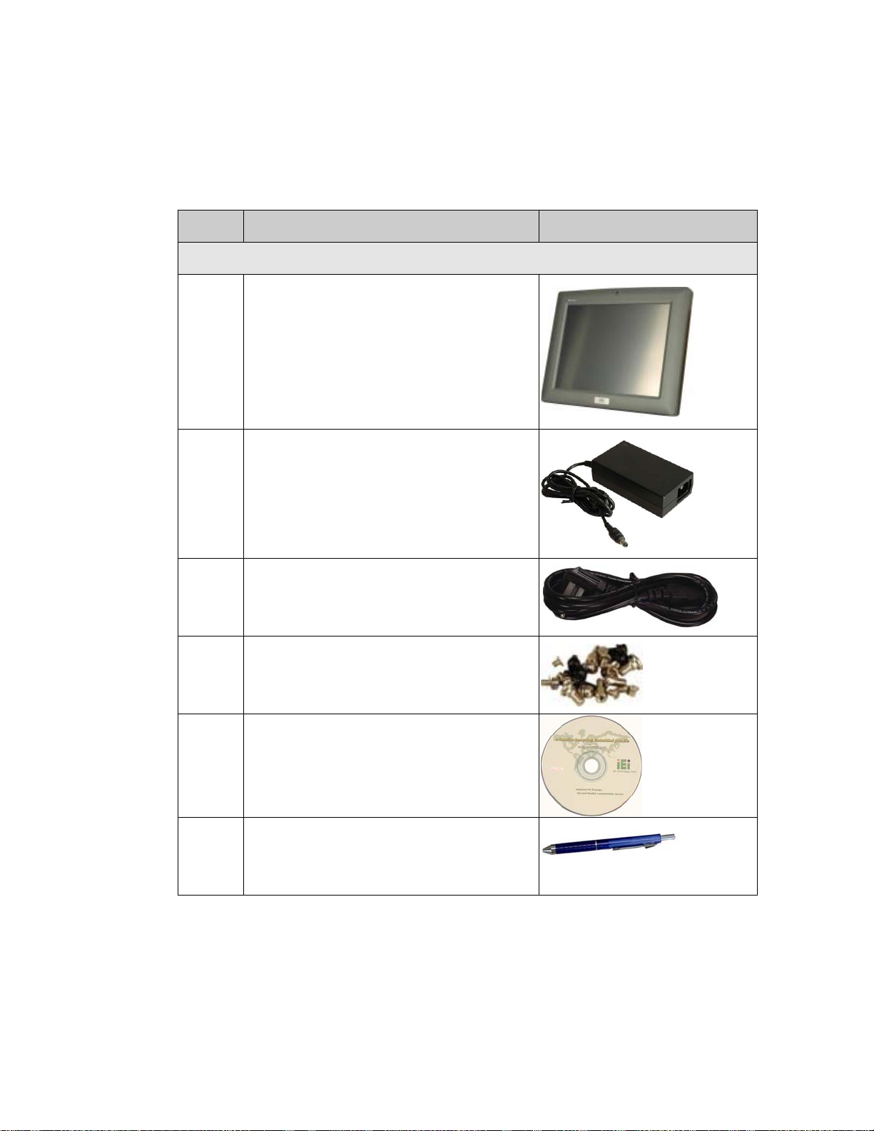
3.1.1 Packing List
The AFL-08AH-N270-CR flat panel PC is shipped with the following components:
Quantity Item Image
Standard
1 AFL-08AH-N270-CR
1 Power adapter
(PMP60-12-B12)
AFL-08AH-N270-CR Panel PC
1 Power cord
1 Screw kit
1 User manual CD and driver CD
1 Touch pen
If any of these items are missing or damaged, contact the distributor or sales
representative immediately.
Page 20
Page 35

AFL-08AH-N270-CR Panel PC
Chapter
4
4 Installation
Page 21
Page 36

4.1 Anti-static Precautions
WARNING:
Failure to take ESD precautions during the maintenance of the
AFL-08AH-N270-CR may result in permanent damage to the
AFL-08AH-N270-CR and severe injury to the user.
WARNING:
To avoid risk of electric shock, the AFL-08AH-N270-CR must only be
connected to a supply mains with protective earth.
AFL-08AH-N270-CR Panel PC
Electrostatic discharge (ESD) can cause serious damage to electronic components,
including the AFL-08AH-N270-CR. Dry climates are especially susceptible to ESD. It is
therefore critical that whenever the AFL-08AH-N270-CR is accessed internally, or any
other electrical component is handled, the following anti-static precautions are strictly
adhered to.
Wear an anti-static wristband: - Wearing a simple anti-static wristband can
help to prevent ESD from damaging the board.
Self-grounding: - Before handling the board touch any grounded conducting
material. During the time the board is handled, frequently touch any
conducting materials that are connected to the ground.
Use an anti-static pad: - When configuring the AFL-08AH-N270-CR, place it
on an antic-static pad. This reduces the possibility of ESD damaging the
AFL-08AH-N270-CR.
Only handle the edges of the PCB: - When handling the PCB, hold the PCB
by the edges.
Page 22
Page 37

AFL-08AH-N270-CR Panel PC
4.2 Installation Precautions
When installing the flat panel PC, please follow the precautions listed below:
Power turned off: When installing the flat panel PC, make sure the power is
off. Failing to turn off the power may cause severe injury to the body and/or
damage to the system.
Certified Engineers: Only certified engineers should install and modify
onboard functionalities.
Anti-static Discharge : If a user open the rear panel of the flat panel PC, to
configure the jumpers or plug in added peripheral devices, ground themselves
first and wear and anti-static wristband.
4.3 Preinstalled Components
The following components are all preinstalled.
Motherboard
TFT LCD screen
1.0 GB DDR2 memory module
Resistive type touch screen
Wireless LAN module
CF card
Component installation is described in the following sections.
4.4 Installation and Configuration Steps
The following installation steps must be followed.
Step 1: Unpack the flat panel PC
Step 2: Configure the system
Step 3: Connect peripheral devices to the bottom panel of the flat panel PC
Step 4: Mount the flat panel PC Step 0:
Page 23
Page 38

4.5 Removing the Back Cover
WARNING:
Do not modify this equipment without authorization of the
manufacturer.
Only certified engineers should install and modify the hardware
settings. Incorrect settings can cause irreparable damage to the
system.
AFL-08AH-N270-CR Panel PC
WARNING:
Over-tightening back cover screws will crack the plastic frame.
Maximum torque for cover screws is 5 kg-cm (0.36 lb-ft/0.49 Nm).
To access the AFL-08AH-N270-CR internally the back cover must be removed. To remove
the back cover, please follow the steps below.
Step 1: Remove the retention screws (
Figure 4-1) and lift the cover off the flat panel PC.
Page 24
Figure 4-1: Back Cover Retention Screws
Step 2: Lift the back cover off the system.
Page 39

AFL-08AH-N270-CR Panel PC
Step 3: Remove the retention screws securing the internal aluminum cover (Figure 5-2).
Figure 4-2: Aluminum Back Cover Retention Screws
Step 4: Lift the aluminum cover off the AFL-08AH-N270-CR. Step 0:
4.6 Jumper Settings
NOTE:
A jumper is a metal bridge used to close an
electrical circuit. It consists of two or three metal
pins and a small metal clip (often protected by a
plastic cover) that slides over the pins to connect
them. To CLOSE/SHORT a jumper means
connecting the pins of the jumper with the plastic
clip and to OPEN a jumper means removing the
plastic clip from a jumper.
4.6.1 Access the Jumpers
To access the jumpers, remove the back cover. To remove the back cover, please refer to
Section
4.5.
Page 25
Page 40

4.6.2 Clear CMOS Jumper
AFL-08AH-N270-CR Panel PC
Jumper Label:
Jumper Type:
Jumper Settings:
If the AFL-08AH-N270-CR fails to boot due to improper BIOS settings, the clear CMOS
jumper clears the CMOS data and resets the system BIOS information. To do this, use the
jumper cap to close the pins for a few seconds then remove the jumper clip.
If the “CMOS Settings Wrong” message is displayed during the boot up process, the fault
may be corrected by pressing the F1 to enter the CMOS Setup menu. Do one of the
following:
Enter the correct CMOS setting
Load Optimal Defaults
Load Failsafe Defaults.
After having done one of the above, save the changes and exit the CMOS Setup menu.
J_CMOS1
3-pin header
Table 4-1
See
The clear CMOS jumper settings are shown in
Clear CMOS Description
Short 1 - 2 Keep CMOS Setup Default
Short 2 - 3 Clear CMOS Setup
Table 4-1: Clear CMOS Jumper Settings
4.7 Mounting the System
WARNING!
When mounting the flat panel PC onto an arm, onto the wall or onto a
panel, it is better to have more than one person to help with the installation
to make sure the panel PC does not fall down and get damaged.
Table 4-1.
Page 26
Page 41

AFL-08AH-N270-CR Panel PC
The four methods of mounting the AFL-08AH-N270-CR are listed below.
Wall mounting
Panel mounting
Arm mounting
Rack mounting
The four mounting methods are described below.
4.7.1 Wall Mounting
To mount the flat panel PC onto the wall, please follow the steps below.
Step 1: Select the location on the wall for the wall-mounting bracket.
Step 2: Carefully mark the locations of the four screw holes in the bracket on the wall.
Step 3: Drill four pilot holes at the marked locations on the wall for the bracket retention
screws.
Step 4: Align the wall-mounting bracket screw holes with the pilot holes.
Step 5: Secure the mounting-bracket to the wall by inserting the retention screws into
the four pilot holes and tightening them (
Figure 4-3).
Figure 4-3: Wall-mounting Bracket
Page 27
Page 42

Step 6: Insert the four monitor mounting screws provided in the wall mount kit into the
four screw holes on the real panel of the flat panel PC and tighten until the screw
AFL-08AH-N270-CR Panel PC
shank is secured against the rear panel (
Figure 4-4).
WARNING:
Please use the M4 screws provided in the wall mount kit for the rear panel.
If the screw is missing, the thread depth of the replacement screw should
be not more than 4 mm.
Step 7: Align the mounting screws on the monitor rear panel with the mounting holes on
the bracket.
Step 8: Carefully insert the screws through the holes and gently pull the monitor
downwards until the monitor rests securely in the slotted holes (
Ensure that all four of the mounting screws fit snuggly into their respective
slotted holes.
Figure 4-4).
NOTE:
In the diagram below the bracket is already installed on the wall.
Page 28
Page 43

AFL-08AH-N270-CR Panel PC
Figure 4-4: Chassis Support Screws
Step 9: Secure the panel PC by fastening the retention screw of the wall-mounting
bracket. (
Figure 4-5).
Figure 4-5: Secure the Panel PC
Page 29
Page 44

4.7.2 Panel Mounting
To mount the AFL-08AH-N270-CR flat panel PC into a panel, please follow the steps
below.
Step 1: Select the position on the panel to mount the flat panel PC.
Step 2: Cut out a section from the panel that corresponds to the rear panel dimensions
of the flat panel PC. Take care that the panel section that is cut out is smaller
than the overall size of the frame that surrounds the flat panel PC but just large
AFL-08AH-N270-CR Panel PC
enough for the rear panel of the flat panel PC to fit through (see
Figure 4-6).
Figure 4-6: AFL-08AH-N270-CR Panel Opening
Step 3: Slide the flat panel PC through the hole until the frame is flush against the panel.
Step 4: Insert the panel mounting clamps into the pre-formed holes along the edges of
Page 30
the chassis, behind the frame.
Step 5: Tighten the screws that pass through the panel mounting clamps until the plastic
caps at the front of all the screws are firmly secured to the panel (
Figure 4-7).
Page 45

AFL-08AH-N270-CR Panel PC
Figure 4-7: Tighten the Panel Mounting Clamp Screws
4.7.3 Arm Mounting
The AFL-08AH-N270-CR is VESA (Video Electronics Standards Association) compliant
and can be mounted on an arm with a 75mm interface pad. To mount the
AFL-08AH-N270-CR on an arm, please follow the steps below.
Step 1: The arm is a separately purchased item. Please correctly mount the arm onto
the surface it uses as a base. To do this, refer to the installation documentation
that came with the mounting arm.
NOTE:
When purchasing the arm please ensure that it is VESA compliant and that
the arm has a 75 mm interface pad. If the mounting arm is not VESA
compliant it cannot be used to support the AFL-08AH-N270-CR flat panel
PC.
Page 31
Page 46

Step 2: Once the mounting arm has been firmly attached to the surface, lift the flat panel
PC onto the interface pad of the mounting arm.
Step 3: Align the retention screw holes on the mounting arm interface with those in the
flat panel PC. The AFL-08AH-N270-CR arm mount retention screw holes are
AFL-08AH-N270-CR Panel PC
shown in
Figure 4-8.
Figure 4-8: Arm Mounting Retention Screw Holes
Step 4: Secure the flat panel PC to the interface pad by inserting four retention screws
through the bottom of the mounting arm interface pad and into the flat panel PC.
Step 0:
4.7.4 Cabinet and Rack Installation
The AFL-08AH-N270-CR flat panel PC can be installed into a cabinet or rack. The
installation procedures are similar to the panel mounting installation. To do this, please
follow the steps below:
Page 32
Page 47

AFL-08AH-N270-CR Panel PC
NOTE:
When purchasing the cabinet/rack installation bracket, make sure it is
compatible with both the AFL-08AH-N270-CR flat panel PC and the
rack/cabinet into which the AFL-08AH-N270-CR is installed.
Step 1: Slide the rear chassis of the AFL-08AH-N270-CR flat panel PC through the
rack/cabinet bracket until the aluminum frame is flush against the front of the
bracket (
Figure 4-9).
Figure 4-9: The Rack/Cabinet Bracket
Step 2: Insert the rack mounting clamps into the pre-formed holes along the edges of
the flat panel PC, behind the ABS/PC plastic frame. There are a total of 4 rack
mounting clamps.
Step 3: Tighten the screws that pass through the rack mounting clamps until the plastic
caps at the front of all the screws are firmly secured to the bracket (
Figure 4-10).
Page 33
Page 48

AFL-08AH-N270-CR Panel PC
Figure 4-10: Secure the Rack/Cabinet Bracket
Step 4: Slide the flat panel PC with the attached rack/cabinet bracket into a rack or
cabinet (
Figure 4-11).
Figure 4-11: Install into a Rack/Cabinet
Page 34
Page 49

AFL-08AH-N270-CR Panel PC
Step 5: Once the flat panel PC with the attached rack/cabinet bracket has been properly
inserted into the rack or cabinet, secure the front of the rack/cabinet bracket to
the front of the rack or cabinet (
4.8 Bottom Panel Connectors
4.8.1 LAN Connection
There are two external RJ-45 LAN connectors. The RJ-45 connector enables connection
to an external network. To connect a LAN cable with an RJ-45 connector, please follow
the instructions below.
Step 1: Locate the RJ-45 connectors on the bottom panel of the AFL-08AH-N270-CR.
Step 2: Align the connectors. Align the RJ-45 connector on the LAN cable with one of
the RJ-45 connectors on the bottom panel of the AFL-08AH-N270-CR. See
Figure 4-12.
Figure 4-11).
Figure 4-12: LAN Connection
Step 3: Insert the LAN cable RJ-45 connector. Once aligned, gently insert the LAN
cable RJ-45 connector into the onboard RJ-45 connector. Step 0:
Page 35
Page 50

4.8.2 USB Device Connection
WARNING:
Accessory equipment connected to the analog and digital interfaces
must be in compliance with the respective nationally harmonized IEC
standards (i.e. IEC 60950 for data processing equipment, IEC 60065
for video equipment, IEC 61010-1 for laboratory equipment, and IEC
60601-1 for medical equipment.)
Furthermore all configurations shall comply with the system standard
IEC 60601-1-1. Everybody who connects additional equipment to the
signal input part or signal output part configures a medical system, and
is therefore, responsible that the system complies with the
AFL-08AH-N270-CR Panel PC
requirements of the system standard IEC 60601-1-1.
The unit is for exclusive interconnection with IEC 60601-1 certified
equipment in the patient environment and IEC 60XXX certified
equipment outside of the patient environment. If in doubt, consult the
technical services department or your local representative.
There are six external USB 2.0 connectors. To connect a USB 2.0 or USB 1.1 device,
please follow the instructions below.
Step 1: Located the USB connectors. The locations of the USB connectors are shown
in Chapter 2.
Step 2: Align the connectors. Align the USB device connector with one of the
connectors on the bottom panel. See
Figure 4-13.
Page 36
Page 51

AFL-08AH-N270-CR Panel PC
Figure 4-13: USB Device Connection
Step 3: Insert the device connector. Once aligned, gently insert the USB device
connector into the onboard connector. Step 0:
Page 37
Page 52

AFL-08AH-N270-CR Panel PC
Chapter
5
5 System Maintenance
Page 38
Page 53

AFL-08AH-N270-CR Panel PC
WARNING:
Do not modify this equipment without authorization of the
manufacturer.
Only certified engineers should install and modify the hardware
settings. Incorrect settings can cause irreparable damage to the
system.
5.1 System Maintenance Introduction
If the components of the AFL-08AH-N270-CR fail, please contact the system reseller or
vendor. Components that can be replaced include:
CF Module
Wireless LAN module
SO-DIMM module
Back cover removal instructions for the AFL-08AH-N270-CR are described below.
5.2 Anti-static Precautions
WARNING:
Failure to take ESD precautions during the maintenance of the
AFL-08AH-N270-CR may result in permanent damage to the
AFL-08AH-N270-CR and severe injury to the user.
Electrostatic discharge (ESD) can cause serious damage to electronic components,
including the AFL-08AH-N270-CR. Dry climates are especially susceptible to ESD. It is
therefore critical that whenever the AFL-08AH-N270-CR is accessed internally, or any
Page 39
Page 54

other electrical component is handled, the following anti-static precautions are strictly
adhered to.
Wear an anti-static wristband: - Wearing a simple anti-static wristband can
help to prevent ESD from damaging the board.
Self-grounding: - Before handling the board touch any grounded conducting
material. During the time the board is handled, frequently touch any
conducting materials that are connected to the ground.
Use an anti-static pad: - When configuring the AFL-08AH-N270-CR, place it
on an antic-static pad. This reduces the possibility of ESD damaging the
AFL-08AH-N270-CR.
Only handle the edges of the PCB: - When handling the PCB, hold the PCB
by the edges.
5.3 Turn off the Power
AFL-08AH-N270-CR Panel PC
WARNING:
Failing to turn off the system before opening it can cause permanent
damage to the system and serious or fatal injury to the user.
Before any maintenance procedures are carried out on the system, make sure the system
is turned off.
5.4 Opening the System
5.4.1 Removing the Back Cover
WARNING:
Over-tightening back cover screws will crack the plastic frame.
Maximum torque for cover screws is 5 kg-cm (0.36 lb-ft/0.49 Nm).
Page 40
Page 55

AFL-08AH-N270-CR Panel PC
To access the AFL-08AH-N270-CR internally the back cover must be removed. To remove
the back cover, please follow the steps below.
Step 1: Follow all anti-static procedures. See Section
Step 2: Turn off the power. See Section
Step 3: Remove the retention screws on the back. Remove the retention screws
Figure 5-1) from the back cover.
(
5.3.
5.2.
Figure 5-1: Back Cover Retention Screws
Step 4: Lift the cover off the system. Step 0:
5.4.2 Internal Aluminum Cover Removal
To remove the internal aluminum cover, follow the steps below.
Step 1: Remove the retention screws securing the internal aluminum cover (
Figure 5-2).
Page 41
Page 56

Figure 5-2: Aluminum Back Cover Retention Screws
Step 2: Lift the aluminum cover off the AFL-08AH-N270-CR. Step 0:
5.5 Replacing Components
AFL-08AH-N270-CR Panel PC
5.5.1 Memory Module Replacement
The flat panel PC is preinstalled with a 1 GB DDR2 memory module. If the memory
module is fail, follow the instructions below to replace the memory module.
Step 1: Remove the back cover. See Section
Step 2: Remove the internal aluminum back cover. See Section
Step 3: Locate the DDR2 SO-DIMM on the motherboard (
5.4.1 above.
5.4.2 above.
Figure 5-3).
Page 42
Figure 5-3: AFL-10A-N270 SO-DIMM Socket Location
Page 57

AFL-08AH-N270-CR Panel PC
Step 4: Remove the DDR memory module by pulling both the spring retainer clips
outward from the socket.
Step 5: Grasp the DDR memory module by the edges and carefully pull it out of the
socket.
Step 6: Install the new DDR memory module by pushing it into the socket at an angle
Figure 5-4).
(
Step 7: Gently pull the spring retainer clips of the SO-DIMM socket out and push the
rear of the DDR memory module down (
Step 8: Release the spring retainer clips on the SO-DIMM socket. They clip into place
and secure the DDR memory module in the socket.Step 0:
Figure 5-4).
Figure 5-4: DDR SO-DIMM Module Installation
5.5.2 CF Card Replacement
The AFL-08AH-N270-CR is preinstalled one CF Type II card. To replace the CF card,
follow the instructions below.
Step 1: Follow all anti-static procedures. See Section
Step 2: Turn off the power. See Section
Step 3: Remove the back cover. See Section
Step 4: Locate the CF slot. Remove the old CF card (
5.3.
5.4.1.
5.2.
Figure 5-5).
Page 43
Page 58

AFL-08AH-N270-CR Panel PC
Figure 5-5: CF Card Location
Step 5: Insert a new CF card into the slot.
Step 6: Replace the plastic back cover..
Step 7: Once replaced reinsert the nine previously removed retention screws. Step 0:
WARNING:
Over-tightening back cover screws will crack the plastic frame.
Maximum torque for cover screws is 5 kg-cm (0.36 lb-ft/0.49 Nm).
5.6 Reinstalling the Covers
WARNING:
Failing to reinstall the covers may result in permanent damage to the
system. Please make sure all coverings are properly installed.
Page 44
When maintenance procedures are complete, please make sure all the covers are
replaced, including the following:
Page 59

AFL-08AH-N270-CR Panel PC
Aluminum cover
Plastic cover
Page 45
Page 60

AFL-08AH-N270-CR Panel PC
Chapter
6
6 AMI BIOS Setup
Page 46
Page 61

AFL-08AH-N270-CR Panel PC
6.1 Introduction
A licensed copy of AMI BIOS is preprogrammed into the ROM BIOS. The BIOS setup
program allows users to modify the basic system configuration. This chapter describes
how to access the BIOS setup program and the configuration options that may be
changed.
6.1.1 Starting Setup
The AMI BIOS is activated when the computer is turned on. The setup program can be
activated in one of two ways.
1. Press the D
2. Press the D
message appears on the screen. 0.
If the message disappears before the D
again.
ELETE key as soon as the system is turned on or
ELETE key when the “Press Del to enter SETUP”
ELETE key is pressed, restart the computer and try
6.1.2 Using Setup
Use the arrow keys to highlight items, press ENTER to select, use the PageUp and
PageDown keys to change entries, press F1 for help and press E
keys are shown in.
Key Function
Up arrow Move to previous item
Down arrow Move to next item
Left arrow Move to the item on the left hand side
SC to quit. Navigation
Right arrow Move to the item on the right hand side
Esc key Main Menu – Quit and not save changes into CMOS
Status Page Setup Menu and Option Page Setup Menu --
Exit current page and return to Main Menu
Page Up key Increase the numeric value or make changes
Page Dn key Decrease the numeric value or make changes
Page 47
Page 62

F1 key General help, only for Status Page Setup Menu and Option
F2 /F3 key Change color from total 16 colors. F2 to select color
F10 key Save all the CMOS changes, only for Main Menu
Table 6-1: BIOS Navigation Keys
6.1.3 Getting Help
When F1 is pressed a small help window describing the appropriate keys to use and the
AFL-08AH-N270-CR Panel PC
Page Setup Menu
forward.
possible selections for the highlighted item appears. To exit the Help Window press E
the F1 key again.
6.1.4 Unable to Reboot After Configuration Changes
If the computer cannot boot after the system configuration is made, clear the CMOS.
6.1.5 BIOS Menu Bar
The menu bar on top of the BIOS screen has the following main items:
Main Changes the basic system configuration.
Advanced Changes the advanced system settings.
PCIPnP Changes the advanced PCI/PnP Settings
Boot Changes the system boot configuration.
Security Sets User and Supervisor Passwords.
Chipset Changes the chipset settings.
Exit Selects exit options and loads default settings
SC or
Page 48
The following sections completely describe the configuration options found in the menu
items at the top of the BIOS screen and listed above.
Page 63

AFL-08AH-N270-CR Panel PC
6.2 Main
The Main BIOS menu (4BIOS Menu 1) appears when the BIOS Setup program is entered.
The Main menu gives an overview of the basic system information.
BIOS Menu 1: Main
System Overview
The System Overvie w lists a brief summary of different system components. The fields in
System Overview cannot be changed. The items shown in the system overview include:
AMI BIOS: Displays auto-detected BIOS information
o Version: Current BIOS version
o Build Date: Date the current BIOS version was made
o ID: Installed BIOS ID
Processor: Displays auto-detected CPU specifications
o Type: Names the currently installed processor
o Speed: Lists the processor speed
o Count: The number of CPUs on the CPU card
System Memory: Displays the auto-detected system memory.
o Size: Lists memory size
Page 49
Page 64

AFL-08AH-N270-CR Panel PC
The System Overview field also has two user configurable fields:
System Time [xx:xx:xx]
Use the System Time option to set the system time. Manually enter the hours, minutes
and seconds.
System Date [xx/xx/xx]
Use the System Date option to set the system date. Manually enter the day, month and
year.
6.3 Advanced
Use the Advanced menu (4BIOS Menu 2) to configure the CPU and peripheral devices
through the following sub-menus:
WARNING:
Setting the wrong values in the sections below may cause the system
to malfunction. Make sure that the settings made are compatible with
the hardware.
CPU Configuration (see Section 46.3.1)
IDE Configuration (see Section
SuperIO Configuration (see Section
Hardware Health Configuration (see Section
Power Configuration (see Section
Remote Access Configuration (see Section
USB Configuration (see Section
46.3.2)
46.3.3)
46.3.4)
46.3.5)
46.3.6)
46.3.8)
Page 50
Page 65

AFL-08AH-N270-CR Panel PC
BIOS Menu 2: Advanced
6.3.1 CPU Configuration
Use the CPU Configuration menu (4BIOS Menu 3) to view detailed CPU specifications
and configure the CPU.
BIOS Menu 3: CPU Configuration
Page 51
Page 66

The CPU Configuration menu (BIOS Menu 3) lists the following CPU details:
Manufacturer: Lists the name of the CPU manufacturer
Brand String: Lists the brand name of the CPU being used
Frequency: Lists the CPU processing speed
FSB Speed: Lists the FSB speed
Cache L1: Lists the CPU L1 cache size
Cache L2: Lists the CPU L2 cache size
6.3.2 IDE Configuration
Use the IDE Configuration menu (4BIOS Menu 4) to change and/or set the configuration
of the IDE devices installed in the system.
AFL-08AH-N270-CR Panel PC
BIOS Menu 4: IDE Configuration
ATA/IDE Configurations [Compatible]
Use the ATA/IDE Configurations option to configure the ATA/IDE controller.
Page 52
Disabled
Compatible D
Disables the on-board ATA/IDE controller.
EFAULT
Configures the on-board ATA/IDE controller to be in
Page 67

AFL-08AH-N270-CR Panel PC
compatible mode. In this mode, a SATA channel will
replace one of the IDE channels. This mode supports up
to 4 storage devices.
Enhanced
Configures the on-board ATA/IDE controller to be in
Enhanced mode. In this mode, IDE channels and SATA
channels are separated. This mode supports up to 6
storage devices. Some legacy OS do not support this
mode.
Legacy IDE Channels [PATA Pri, SATA Sec]
SA TA Only
Reserved
SA TA Pri, PATA Sec D
PATA Only
Only the SATA drives are enabled.
The IDE channel is reserved
EFAULT
The IDE drives are enabled on the primary
The IDE drives are enabled on the Primary
IDE channel. The SATA drives are enabled on
the Secondary IDE channel.
and secondary IDE channels. SATA drives
are disabled.
IDE Master and IDE Slave
When entering setup, BIOS auto detects the presence of IDE devices. BIOS displays the
status of the auto detected IDE devices. The following IDE devices are detected and are
shown in the IDE Configuration menu:
Primary IDE Master
Primary IDE Slave
Secondary IDE Master
Secondary IDE Slave
The IDE Configuration menu (
IDE devices installed in the system. If an IDE device is detected, and one of the above
listed four BIOS configuration options are selected, the IDE configuration options shown in
Section
46.3.2.1 appear.
4BIOS Menu 4) allows changes to the configurations for the
Page 53
Page 68

6.3.2.1 IDE Master, IDE Slave
Use the IDE Master and IDE Slave configuration menu to view both primary and
secondary IDE device details and configure the IDE devices connected to the system.
AFL-08AH-N270-CR Panel PC
BIOS Menu 5: IDE Master and IDE Slave Configuration
Auto-Detected Drive Parameters
The “grayed-out” items in the left frame are IDE disk drive parameters automatically
detected from the firmware of the selected IDE disk drive. The drive parameters are listed
as follows:
Device: Lists the device type (e.g. hard disk, CD-ROM etc.)
Type: Indicates the type of devices a user can manually select
Vendor: Lists the device manufacturer
Size: List the storage capacity of the device.
LBA Mode: Indicates whether the LBA (Logical Block Addressing) is a
method of addressing data on a disk drive is supported or not.
Page 54
Page 69

AFL-08AH-N270-CR Panel PC
Block Mode: Block mode boosts IDE drive performance by increasing the
amount of data transferred. Only 512 bytes of data can be transferred per
interrupt if block mode is not used. Block mode allows transfers of up to 64 KB
per interrupt.
PIO Mode: Indicates the PIO mode of the installed device.
Async DMA: Indicates the highest Asynchronous DMA Mode that is
supported.
Ultra DMA: Indicates the highest Synchronous DMA Mode that is supported.
S.M.A.R.T.: Indicates whether or not the Self-Monitoring Analysis and
Reporting Technology protocol is supported.
32Bit Data Transfer: Enables 32-bit data transfer.
T ype [Auto]
Use the Type BIOS option select the type of device the AMIBIOS attempts to boot from
after the Power-On Self-Test (POST) is complete.
Not Installed
Auto DEFAULT
CD/DVD
ARMD
BIOS is prevented from searching for an IDE disk
drive on the specified channel.
The BIOS auto detects the IDE disk drive type
attached to the specified channel. This setting should
be used if an IDE hard disk drive is attached to the
specified channel.
The CD/DVD option specifies that an IDE CD-ROM
drive is attached to the specified IDE channel. The
BIOS does not attempt to search for other types of
IDE disk drives on the specified channel.
This option specifies an ATAPI Removable Media
Device. These include, but are not limited to:
ZIP
LS-120
Page 55
Page 70

LBA/Large Mode [Auto]
Use the LBA/Large Mode option to disable or enable BIOS to auto detects LBA (Logical
Block Addressing). LBA is a method of addressing data on a disk drive. In LBA mode, the
maximum drive capacity is 137 GB.
AFL-08AH-N270-CR Panel PC
Disabled
Auto DEFAULT
Block (Multi Sector Transfer) [Auto]
Use the Block (Multi Sector Transfer) to disable or enable BIOS to auto detect if the
device supports multi-sector transfers.
Disabled
Auto DEFAULT
BIOS is prevented from using the LBA mode control on
the specified channel.
BIOS auto detects the LBA mode control on the specified
channel.
BIOS is prevented from using Multi-Sector Transfer on the
specified channel. The data to and from the device occurs
one sector at a time.
BIOS auto detects Multi-Sector Transfer support on the
drive on the specified channel. If supported the data
transfer to and from the device occurs multiple sectors at
a time.
PIO Mode [Auto]
Use the PIO Mode option to select the IDE PIO (Programmable I/O) mode program timing
cycles between the IDE drive and the programmable IDE controller. As the PIO mode
increases, the cycle time decreases.
Auto DEFAULT
0
1
2
Page 56
BIOS auto detects the PIO mode. Use this value if the IDE disk
drive support cannot be determined.
PIO mode 0 selected with a maximum transfer rate of 3.3MBps
PIO mode 1 selected with a maximum transfer rate of 5.2MBps
PIO mode 2 selected with a maximum transfer rate of 8.3MBps
Page 71

AFL-08AH-N270-CR Panel PC
3
4
DMA Mode [Auto]
Use the DMA Mode BIOS selection to adjust the DMA mode options.
Auto DEFAULT
S.M.A.R.T [Auto]
Use the S.M.A.R.T option to auto-detect, disable or enable Self-Monitoring Analysis and
Reporting Technology (SMART) on the drive on the specified channel. S.M.A.R.T predicts
PIO mode 3 selected with a maximum transfer rate of 11.1MBps
PIO mode 4 selected with a maximum transfer rate of 16.6MBps
(This setting generally works with all hard disk drives
manufactured after 1999. For other disk drives, such as IDE
CD-ROM drives, check the specifications of the drive.)
BIOS auto detects the DMA mode. Use this value if the IDE
disk drive support cannot be determined.
impending drive failures. The S.M.A.R.T BIOS option enables or disables this function.
Auto DEFAULT
Disabled
Enabled
32Bit Data Transfer [Enabled]
Use the 32Bit Data Transfer BIOS option to enables or disable 32-bit data transfers.
Disabled
Enabled DEFAULT
Prevents BIOS from using the HDD SMART feature.
Allows BIOS to use the HDD SMART feature
Prevents the BIOS from using 32-bit data transfers.
BIOS auto detects HDD SMART support.
Allows BIOS to use 32-bit data transfers on supported
hard disk drives.
Page 57
Page 72

6.3.3 Super IO Configuration
Use the Super IO Configuration menu (4BIOS Menu 6) to set or change the
configurations for the FDD controllers, parallel ports and serial ports.
AFL-08AH-N270-CR Panel PC
BIOS Menu 6: Super IO Configuration
Serial Port1 Address [3F8/IRQ4]
Use the Serial Port1 Address option to select the Serial Port 1 base address.
Disabled
3F8/IRQ4 DEFAULT
3E8/IRQ4
2E8/IRQ3
No base address is assigned to Serial Port 1
Serial Port 1 I/O port address is 3F8 and the interrupt
address is IRQ4
Serial Port 1 I/O port address is 3E8 and the interrupt
address is IRQ4
Serial Port 1 I/O port address is 2E8 and the interrupt
address is IRQ3
Page 58
Page 73

AFL-08AH-N270-CR Panel PC
Serial Port1 Mode [Normal]
Use the Serial Port1 Mode option to select the transmitting and receiving mode for the
first serial port.
Normal DEFAULT
IrDA
ASK IR
Serial Port 1 mode is IrDA
Serial Port 1 mode is ASK IR
Serial Port 1 mode is normal
6.3.4 Hardware Health Configuration
The Hardware Health Configuration menu (4BIOS Menu 7) shows the operating
temperature, fan speeds and system voltages.
BIOS Menu 7: Hardware Health Configuration
CPU FAN Mode Setting [Full On Mode]
Use the CPU FAN Mode Setting option to configure the second fan.
Full On Mode D
EFAULT
Fan is on all the time
Page 59
Page 74

AFL-08AH-N270-CR Panel PC
Automatic mode
PWM Manual mode
When the CPU FAN Mode Setting option is in the Automatic Mode, the following
parameters can be set.
CPU Temp. Limit of OFF
CPU Temp. Limit of Start
CPU Fan Start PWM
Slope PWM
When the CPU FAN Mode Setting option is in the PWM Manual Mode, the following
parameters can be set.
CPU Fan PWM control
Fan is off when the temperature is low
enough. Parameters must be set by the
user.
Pulse width modulation set manually
CPU Temp. Limit of OFF [000]
WARNING:
Setting this value too high may cause the fan to stop when the CPU is
at a high temperature and therefore cause the system to be damaged.
The CPU Temp. Limit of OFF option can only be set if the CPU FAN Mode Setting
option is set to Automatic Mode. Use the CPU Temp. Limit of OFF option to select the
CPU temperature at which the cooling fan should automatically turn off. To select a value,
select the CPU Temp. Limit of OFF option and enter a decimal number between 000 and
127. The temperature range is specified below.
Minimum Value: 0°C
Maximum Value: 127°C
Page 60
Page 75

AFL-08AH-N270-CR Panel PC
CPU Temp. Limit of Start [020]
WARNING:
Setting this value too high may cause the fan to start only when the
CPU is at a high temperature and therefore cause the system to be
damaged.
The CPU Temp. Limit of Start option can only be set if the CPU FAN Mode Setting
option is set to Automatic Mode. Use the CPU Temp. Limit of Start option to select the
CPU temperature at which the cooling fan should automatically turn on. When the fan
starts, it rotates using the starting pulse width modulation (PWM) specified in the Fan 3
Start PWM option below. To select a value, select the CPU Temp. Limit of Start option
and enter a decimal number between 000 and 127. The temperature range is specified
below.
Minimum Value: 0°C
Maximum Value: 127°C
CPU Fan Start PWM [070]
The Fan 3 Start PWM option can only be set if the CPU FAN Mode Setting option is set
to Automatic Mode. Use the Fan 3 Start PWM option to select the PWM mode the fan
starts to rotate with after the temperature specified in the Temperature 3 Limit of Start is
exceeded. The Super I/O chipset supports 128 PWM modes. To select a value, select the
Fan 3 Start PWM option and enter a decimal number between 000 and 127. The
temperature range is specified below.
PWM Minimum Mode: 0
PWM Maximum Mode: 127
Slope PWM [0.5 PWM]
The Slope PWM 1 option can only be set if the CPU FAN Mode Setting option is set to
Automatic Mode. Use the Slope PWM 1 option to select the linear rate at which the PWM
Page 61
Page 76

mode increases with respect to an increase in temperature. A list of available options is
shown below:
0.125 PWM
0.25 PWM
0.5 PWM
1 PWM
2 PWM
4 PWM
8 PWM
15 PWM
The following system parameters and values are shown. The system parameters that are
monitored are:
AFL-08AH-N270-CR Panel PC
System Temperatures: The following system temperatures are monitored
o CPU Temperature
o System Temperature
Fan Speeds: The CPU cooling fan speed is monitored.
o CPU Fan Speed
Voltages: The following system voltages are monitored
o CPU Core
o +1.05V
o +3.30V
o +5.00V
o +12.0 V
o +1.5V
o +1.8V
o 5VSB
o VBAT
6.3.5 Power Configuration
Page 62
The Power Configuration menu (4BIOS Menu 8) configures the Advanced Configuration
and Power Interface (ACPI) and Power Management (APM) options.
Page 77

AFL-08AH-N270-CR Panel PC
BIOS Menu 8: Power Configuration
6.3.5.1 ACPI configuration
The ACPI Configuration menu (4BIOS Menu 9) configures the Advanced Configuration
and Power Interface (ACPI).
BIOS Menu 9: ACPI Configuration
Page 63
Page 78

Suspend Mode [S1(POS)]
Use the Suspend Mode BIOS option to specify the sleep state the system enters when it
is not being used.
AFL-08AH-N270-CR Panel PC
S1 (POS) DEFAULT
S3 (STR)
System appears off. The CPU is stopped; RAM is
refreshed; the system is running in a low power mode.
System appears off. The CPU has no power; RAM is in
slow refresh; the power supply is in a reduced power
mode.
6.3.6 APM Configuration
The APM Configuration menu (BIOS Menu 10) allows the advanced power
management options to be configured.
BIOS Menu 10: Advanced Power Management Configuration
Restore on AC Power Loss [Last State]
Use the Restore on AC Power Loss BIOS option to specify what state the system
returns to if there is a sudden loss of power to the system.
Page 64
Page 79

AFL-08AH-N270-CR Panel PC
Power Off
Power On
Last State D
Power Button Mode [On/Off]
Use the Power Button Mode BIOS to specify how the power button functions.
On/Off D
Suspend
Resume on Keyboard/Mouse [Disabled]
Use the Resume on Keyboard/Mouse BIOS option to enable activity on either the
The system remains turned off
The system turns on
EFAULT
EFAULT
When the power button is pressed the system goes into
The system returns to its previous state. If it was on, it
turns itself on. If it was off, it remains off.
When the power button is pressed the system is either
turned on or off
suspend mode
keyboard or mouse to rouse the system from a suspend or standby state. That is, the
system is roused when the mouse is moved or a button on the keyboard is pressed.
Disabled DEFAULT
Resume On
KeyBoard
Resume On
Mouse
Enabled
Resume on Ring [Disabled]
Use the Resume on Ring BIOS option to enable activity on the RI (ring in) modem line to
rouse the system from a suspend or standby state. That is, the system will be roused by
Wake event not generated by activity on the
Wake event not generated by activity on the
Wake event generated by activity on the
Wake event not generated by activity on the
keyboard or mouse
keyboard
mouse
keyboard or mouse
an incoming call on a modem.
Page 65
Page 80

AFL-08AH-N270-CR Panel PC
Disabled D
Enabled
Resume on PCI-Express W AKE# [Enabled]
Use the Resume PCI-Express WAKE# BIOS option to enable activity on the
PCI-Express WAKE# signal to rouse the system from a suspend or standby state.
Disabled
Enabled D
Resume On RTC Alarm [Disabled]
Use the Resume On RTC Alarm option to specify the time the system should be roused
from a suspended state.
EFAULT
Wake event generated by an incoming call
Wake event not generated by PCI-Express WAKE#
EFAULT
Wake event not generated by an incoming call
signal activity
Wake event generated by PCI-Express WAKE# signal
activity
Disabled D
Enabled
EFAULT
If selected, the following appears with values that
The real time clock (RTC) cannot generate a wake
event
can be selected:
RTC Alarm Date (Days)
System Time
After setting the alarm, the computer turns itself on
from a suspend state when the alarm goes off.
6.3.7 Remote Configuration
Use the Remote Access Configuration menu (BIOS Menu 11) to configure remote
access parameters. The Remote Access Configuration is an AMIBIOS feature and
allows a remote host running a terminal program to display and configure the BIOS
settings.
Page 66
Page 81

AFL-08AH-N270-CR Panel PC
BIOS Menu 11: Remote Access Configuration [Advanced]
Remote Access [Disabled]
Use the Remote Access option to enable or disable access to the remote functionalities
of the system.
Disabled D
Enabled
EFAULT
Remote access configuration options shown below
Remote access is disabled.
appear:
Serial Port Number
Serial Port Mode
Redirection after BIOS POST
Terminal Type
These configuration options are discussed below.
Page 67
Page 82

Serial Port Number [COM1]
Use the Serial Port Number option allows to select the serial port used for remote
access.
AFL-08AH-N270-CR Panel PC
COM1 D
NOTE: Make sure the selected COM port is enabled through the Super I/O configuration
menu.
Base Address, IRQ [3F8h,4]
The Base Address, IRQ option cannot be configured and only shows the interrupt
address of the serial port listed above.
Serial Port Mode [115200 8,n,1]
Use the Serial Port Mode option to select baud rate through which the console redirection
is made. The following configuration options are available
115200 8,n,1 D
57600 8,n,1
38400 8,n,1
EFAULT
EFAULT
System is remotely accessed through COM1
19200 8,n,1
09600 8,n,1
NOTE:
Identical baud rate setting musts be set on the host (a management
computer running a terminal software) and the slave
Redirection After BIOS POST [Always]
Use the Redirection After BIOS POST option to specify when console redirection should
occur.
Page 68
Disabled
Boot Loader
The console is not redirected after POST
Redirection is active during POST and during Boot
Page 83

AFL-08AH-N270-CR Panel PC
Loader
Always D
Terminal Type [ANSI]
Use the Terminal Type BIOS option to specify the remote terminal type.
ANSI D
VT100
VT-UTF8
6.3.8 USB Configuration
Use the USB Configuration menu (4BIOS Menu 12) to read USB configuration
information and configure the USB settings.
EFAULT
EFAULT
The target terminal type is VT100
The target terminal type is VT-UTF8
Redirection is always active (Some OSes may not
work if set to Always)
The target terminal type is ANSI
BIOS Menu 12: USB Configuration
Page 69
Page 84

USB Functions [Enabled]
Use the USB Function option to enable or disable the USB controllers.
AFL-08AH-N270-CR Panel PC
Disabled
Enabled DEFAULT
USB 2.0 Controller [Enabled]
The USB 2.0 Controller BIOS option enables or disables the USB 2.0 controller
Enabled DEFAULT
Disabled
Legacy USB Support [Enabled]
Use the Legacy USB Support BIOS option to enable USB mouse and USB keyboard
support.
Normally if this option is not enabled, any attached USB mouse or USB keyboard does not
become available until a USB compatible operating system is fully booted with all USB
USB controllers are enabled
USB controllers are disabled
USB function enabled
USB function disabled
drivers loaded. When this option is enabled, any attached USB mouse or USB keyboard
can control the system even when there is no USB driver loaded onto the system.
Disabled
Enabled DEFAULT
Auto
USB2.0 Controller Mode [HiSpeed]
The USB2.0 Controller Mode BIOS option sets the speed of the USB2.0 controller.
FullSpeed
Legacy USB support disabled
Legacy USB support enabled
Legacy USB support disabled if no USB devices are
connected
The controller is capable of operating at full speed
12 Mb/s
Page 70
Page 85

AFL-08AH-N270-CR Panel PC
HiSpeed DEFAULT
6.4 PCI/PnP
Use the PCI/PnP menu (4BIOS Menu 13) to configure advanced PCI and PnP settings.
WARNING:
The controller is capable of operating at high speed
480 Mb/s
Setting wrong values for the BIOS selections in the PCIPnP BIOS
menu may cause the system to malfunction.
BIOS Menu 13: PCI/PnP Configuration
IRQ# [Available]
Use the IRQ# address to specify what IRQs can be assigned to a particular peripheral
device.
Available DEFAULT
The specified IRQ is available to be used by
PCI/PnP devices
Page 71
Page 86

AFL-08AH-N270-CR Panel PC
Reserved
Available IRQ addresses are:
IRQ3
IRQ4
IRQ5
IRQ7
IRQ9
IRQ10
IRQ 11
IRQ 14
IRQ 15
DMA Channel# [Available]
Use the DMA Channel# option to assign a specific DMA channel to a particular PCI/PnP
The specified IRQ is reserved for use by Legacy ISA
devices
device.
Available DEFAULT
Reserved
Available DMA Channels are:
DM Channel 0
DM Channel 1
DM Channel 3
DM Channel 5
DM Channel 6
DM Channel 7
The specified DMA is reserved for use by Legacy
The specified DMA is available to be used by
PCI/PnP devices
ISA devices
Page 72
Page 87
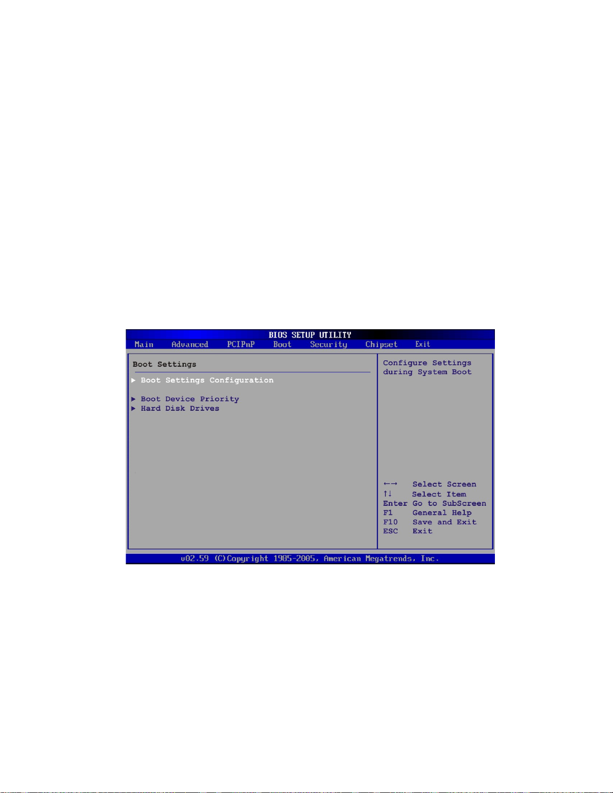
AFL-08AH-N270-CR Panel PC
Reserved Memory Size [Disabled]
Use the Reserved Memory Size BIOS option to specify the amount of memory that
should be reserved for legacy ISA devices.
6.5 Boot
Use the Boot menu (4BIOS Menu 14) to configure system boot options.
Disabled D
16K
32K
64K
EFAULT
16KB reserved for legacy ISA devices
32KB reserved for legacy ISA devices
54KB reserved for legacy ISA devices
No memory block reserved for legacy ISA devices
BIOS Menu 14: Boot
6.5.1 Boot Settings Configuration
Use the Boot Settings Configuration menu (4BIOS Menu 15) to configure advanced system
boot options.
Page 73
Page 88

AFL-08AH-N270-CR Panel PC
BIOS Menu 15: Boot Settings Configuration
Quick Boot [Enabled]
Use the Quick Boot BIOS option to make the computer speed up the boot process.
Disabled
Enabled DEFAULT
Quiet Boot [Disabled]
Use the Quiet Boot BIOS option to select the screen display when the system boots.
Disabled DEFAULT
Enabled
No POST procedures are skipped
OEM Logo displayed instead of POST messages
Some POST procedures are skipped to decrease
the system boot time
Normal POST messages displayed
Page 74
Page 89

AFL-08AH-N270-CR Panel PC
AddOn ROM Display Mode [Force BIOS]
The AddOn ROM Display Mode option allows add-on ROM (read-only memory)
messages to be displayed.
Force BIOS DEFAULT
Keep Current
Bootup Num-Lock [On]
The Bootup Num-Lock BIOS option allows the Number Lock setting to be modified
during boot up.
Does not enable the keyboard Number Lock automatically. To
Off
On DEFAULT
Allows the computer system to force a third party
BIOS to display during system boot.
Allows the computer system to display the
information during system boot.
use the 10-keys on the keyboard, press the Number Lock key
located on the upper left-hand corner of the 10-key pad. The
Number Lock LED on the keyboard lights up when the Number
Lock is engaged.
Allows the Number Lock on the keyboard to be enabled
automatically when the computer system boots up. This allows
the immediate use of the 10-key numeric keypad located on
the right side of the keyboard. To confirm this, the Number
Lock LED light on the keyboard is lit.
Boot From LAN Support [Disabled]
The BOOT From LAN Support option enables the system to be booted from a remote
system.
Enabled
Disabled DEFAULT
Can be booted from a remote system through the
LAN
Cannot be booted from a remote system through the
LAN
Page 75
Page 90

Spread S pectrum Function [Disabled]
The Spread Spectrum Function option can help to improve CPU EMI issues.
AFL-08AH-N270-CR Panel PC
Disabled DEFAULT
Enabled
6.6 Security
Use the Security menu (4BIOS Menu 16) to set system and user passwords.
The spread spectrum mode is disabled
The spread spectrum mode is enabled
BIOS Menu 16: Security
Change Supervisor Password
Use the Change Supervisor Password to set or change a supervisor password. The
default for this option is Not Installed. If a supervisor password must be installed, select
this field and enter the password. After the password has been added, Install appears
next to Change Supervisor Password.
Page 76
Page 91
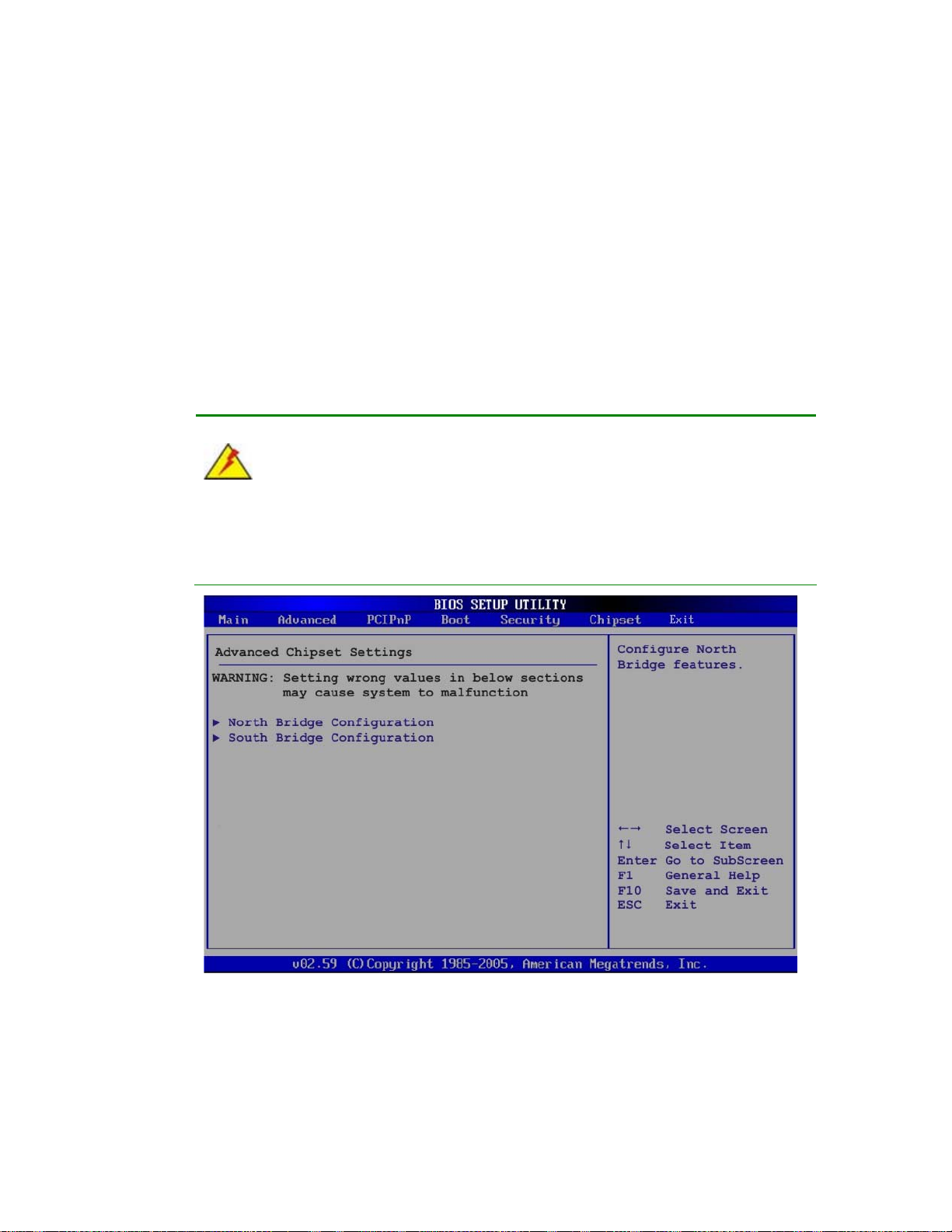
AFL-08AH-N270-CR Panel PC
Change User Password
Use the Change User Password to set or change a user password. The default for this
option is Not Installed. If a user password must be installed, select this field and enter the
password. After the password has been added, Install appears next to Change User
Password.
6.7 Chipset
Use the Chipset menu (4BIOS Menu 17) to access the NorthBridge and SouthBridge
configuration menus
WARNING!
Setting the wrong values for the Chipset BIOS selections in the Chipset BIOS
menu may cause the system to malfunction.
BIOS Menu 17: Chipset
Page 77
Page 92

6.7.1 North Bridge Chipset Configuration
Use the North Bridge Chipset Configuration menu (BIOS Menu 18) to configure the
Northbridge chipset settings.
AFL-08AH-N270-CR Panel PC
BIOS Menu 18:North Bridge Chipset Configuration
Memory Hole [Disabled]
The Memory Hole reserves the memory space between 15MB and 16MB for ISA
expansion cards that require a specified area of memory to work properly. If an older ISA
expansion card is used, please refer to the documentation that came with the card to see if
it is necessary to reserve the space.
Disabled DEFAULT
15 MB–16 MB
Internal Graphics Mode Select [Enable, 8MB]
The Internal Graphic Mode Select option determines the amount of system memory that
Memory is not reserved for ISA expansion cards
Between 15 MB and 16 MB of memory is reserved
for ISA expansion cards
Page 78
can be used by the Internal graphics device.
Page 93

AFL-08AH-N270-CR Panel PC
Disable
Enable, 1MB
Enable, 8MB DEFAULT
DVMT Mode Select [DVMT Mode]
Use the DVMT Mode Select option to select the Intel Dynamic Video Memory Technology
(DVMT) operating mode.
Fixed Mode
DVMT Mode D
Combo Mode
A fixed portion of graphics memory is reserved as
EFAULT
A fixed portion of graphics memory is reserved as
1MB of memory used by internal graphics device
8MB of memory used by internal graphics device
graphics memory.
Graphics memory is dynamically allocated
according to the system and graphics needs.
graphics memory. If more memory is needed,
graphics memory is dynamically allocated
DVMT/FIXED Memory
Use the DVMT/FIXED Memory option to specify the maximum amount of memory that
can be allocated as graphics memory. This option can only be configured for if DVMT
Mode or Fixed Mode is selected in the DVMT Mode Select option. If Combo Mode is
selected, the maximum amount of graphics memory is 128MB. Configuration options are
listed below.
64MB
128MB D
Maximum DVMT
Boot Display Device [Auto]
Use the Boot Display Device option to select the display device used by the system
when it boots. Configuration options are listed below.
according to the system and graphics needs.
EFAULT
Auto
DEFAULT
Page 79
Page 94

CRT
LFP
LFP Panel Type [by H/W]
Use the LFP Panel Type option to select the type of flat panel connected to the system.
Configuration options are listed below.
640x480 18b
800x480 18b
800x600 18b
1024x768 18b
1280x1024 36b
1400x1050 36b
1440x900 36b
AFL-08AH-N270-CR Panel PC
1600x1200 36b
by H/W D
EFAULT
6.7.2 SouthBridge Configuration
The SouthBridge Configuration menu (4BIOS Menu 19) the southbridge chipset to be
configured.
BIOS Menu 19: SouthBridge Chipset Configuration
Page 80
Page 95

AFL-08AH-N270-CR Panel PC
Audio Controller [Auto]
The Audio Controller option enables or disables the audio controller.
6.8 Exit
Use the Exit menu (4BIOS Menu 20) to load default BIOS values, optimal failsafe values
and to save configuration changes.
Auto DEFAULT
Azalia
AC’97 Audio Only
All Disabled
The on-board audio controller automatically
detected and enabled.
The on-board HD Audio controller is enabled.
The on-board AC’97 audio controller is enabled.
The on-board audio controller is disabled.
BIOS Menu 20:Exit
Save Changes and Exit
Use the Save Changes and Exit option to save the changes made to the BIOS options
and to exit the BIOS configuration setup program.
Page 81
Page 96

Discard Changes and Exit
Use the Discard Changes and Exit option to exit the BIOS configuration setup program
without saving the changes made to the system.
Discard Changes
Use the Discard Changes option to discard the changes and remain in the BIOS
configuration setup program.
Load Optimal Defaults
Use the Load Optimal Defaults option to load the optimal default values for each of the
parameters on the Setup menus. F9 key can be used for this operation.
Load Failsafe Defaults
AFL-08AH-N270-CR Panel PC
Use the Load Failsafe Defaults option to load failsafe default values for each of the
parameters on the Setup menus. F8 key can be used for this operation.
Page 82
Page 97

AFL-08AH-N270-CR Panel PC
Appendix
A
A System Specifications
Page 83
Page 98

A.1 Motherboard Specifications
The system comes with an AFLMB-945GSE-N270-AV-R10 motherboard. The detailed
specifications for the motherboard are listed below.
Specification AFLMB-945GSE-N270-AV-R10
Northbridge Intel® 945GSE
Southbridge Intel® ICH7
Processor 1.6 GHz Intel® Atom™ N270 processor
FSB Speed 533 MHz
Supported Memory One 200-pin 2.0 GB (max.) 533 MHz or 400 MHz DDR2 SDRAM SO-DIMM
(system max. 2.0 GB)
System BIOS AMI BIOS
Hard disk drives Two SATA drives
AFL-08AH-N270-CR Panel PC
VGA Integrated in the Intel® 945GSE
LAN Realtek RTL8111CP PCIe GbE Controllers
Expansion Options One PCIe Mini
Super I/O ITE IT8718F
Audio Codec RealTek ALC888
Audio Amplifier NXP TDA1517P
USB Six external USB 2.0 ports
RS-232 Fintek
FAN connector One 4-pin CPU fan connector
A.2 Processor Specifications
The N270 Intel® Atom™ processor specifications are given below.
Parameter Specifications
CPU Speed 1.6 GHz
Bus Speed 533 MHz
Page 84
L2 Cache Size 512 KB
L2 Cache Speed 1.6 GHz
Manufacturing Technology 45 nm
Page 99

AFL-08AH-N270-CR Panel PC
L1 Cache
Thermal Design Power 2.5 W
Tjunction 0 to 90°C
A.3 Screen Specifications
The AFL-08AH-N270-CR comes with a TFT LCD monitor at the front of the flat panel PC.
Specifications for the screens are shown below.
SPECIFICATION AFL-08AH-N270-CR
Model AUO-G084SN05_V8
Size 8.4”
Resolution 800 x 600 (SVGA)
Active Area (mm) 170.4 x 127.8
Pixel Pitch (mm) 0.213 x 0.213
LCD Color Native 262K colors
32 KB instruction cache
24 KB write-back data cache
View Angel (H/V) 140/160
Brightness (cd/m2) 450
Contrast Ratio 600:1
Response Time (ms) 10(Tr) / 25(Tf)
Supply Voltage (V) 3.3
Backlight LED
Dimensions (mm) 203.0 x 142.5 x 8.0
Page 85
Page 100

A.4 Touch Screen Specifications
The AFL-08AH-N270-CR comes with an analog resistive type touch panel. The touch
panel specifications are listed below.
SPECIFICATION AFL-08AH-N270-CR
Model PANJIT 1084403B
Type Analog Resistive Type Touch Panel
Wire Type 4-wire
Viewing Area (mm) 130.75 x 173.38
Active Area (mm) 127.78 x 170.38
Total Transmission 78%
Maximum Voltage DC7V
Connector Type FPC.
AFL-08AH-N270-CR Panel PC
Operating Temperature -10°C ~ 50°C
Operating Humidity 20% ~ 90% RH
Storage Temperature -20°C ~ 70°C
Storage Humidity 20% ~ 90% RH
Dimensions 145.5 x 188 x 2.1
Page 86
 Loading...