

Page 1
ACT-457A Panel PC
IEI Technology Corp.
MODEL:
ACT-457A
Panel PC with Touch Screen and 500 MHz Alchemy AU1250
Gigabit Ethernet, 2 USB, Audio, RS-232/422/485, SATA
IP64 Protection, RoHS Compliant
User Manual
Rev. 1.01 – 15 December 2009
Page i
Page 2
Revision
Date Version Changes
15 December 2009 1.02 Changed rear panel screw picture in Figure 4-1
15 December 2009 1.01 Added some I/O installation notes and warnings
Changed RFID setup
30 September 2009 1.00 Initial release
ACT-457A Panel PC
Page ii
Page 3

ACT-457A Panel PC
COPYRIGHT NOTICE
The information in this document is subject to change without prior notice in order to
improve reliability, design and function and does not represent a commitment on the part
of the manufacturer.
In no event will the manufacturer be liable for direct, indirect, special, incidental, or
consequential damages arising out of the use or inability to use the product or
documentation, even if advised of the possibility of such damages.
This document contains proprietary information protected by copyright. All rights are
Copyright
reserved. No part of this manual may be reproduced by any mechanical, electronic, or
other means in any form without prior written permission of the manufacturer.
TRADEMARKS
All registered trademarks and product names mentioned herein are used for identification
purposes only and may be trademarks and/or registered trademarks of their respective
owners.
Page iii
Page 4

ACT-457A Panel PC
Table of Contents
1 INTRODUCTION.......................................................................................................... 1
1.1 INTRODUCTION........................................................................................................... 2
1.2 FEATURES................................................................................................................... 2
1.3 APPLICATIONS............................................................................................................ 3
1.4 EXTERNAL OVERVIEW................................................................................................ 4
1.5 INTERNAL PARTS ........................................................................................................ 6
1.6 SPECIFICATIONS ......................................................................................................... 7
1.7 DIMENSIONS............................................................................................................... 9
2 INSTALLATION ......................................................................................................... 12
2.1 UNPACKING.............................................................................................................. 13
2.2 PACKING LIST........................................................................................................... 14
2.3 INST ALLATION AND CONFIGURATION STEPS............................................................. 15
2.4 REAR PANEL REMOVAL............................................................................................ 15
2.5 SD CARD INSTALLATION .......................................................................................... 16
2.6 SYSTEM POWER ....................................................................................................... 17
2.6.1 ATX Power Mode (Default) ............................................................................. 17
2.6.2 AT Power Mode................................................................................................ 17
2.7 MOUNTING THE SYSTEM .......................................................................................... 17
2.7.1 Wall Mounting.................................................................................................. 17
2.7.2 In-wall Mounting ............................................................................................. 20
2.7.3 Arm Mounting ..................................................................................................23
2.8 BOTTOM PANEL CONNECTORS ................................................................................. 25
2.8.1 LAN Connection............................................................................................... 25
2.8.2 Serial Device Connection ................................................................................ 25
2.8.3 USB Device Connection................................................................................... 26
2.8.4 Digital I/O Installation .................................................................................... 27
3 RFID READER............................................................................................................ 30
3.1 INTRODUCTION......................................................................................................... 31
3.2 INSTALLATION .......................................................................................................... 31
Page iv
Page 5

ACT-457A Panel PC
RF320 INTERFACE OVERVIEW.................................................................................. 31
3.3
3.4 SERIAL PORT (COM) SETTINGS ............................................................................... 32
3.5 RF320 COMMANDS.................................................................................................. 33
3.5.1 Read Block....................................................................................................... 34
3.5.2 Write Block....................................................................................................... 35
3.5.3 Set Mifare Parameter....................................................................................... 36
3.5.4 Get Mifare Parameter...................................................................................... 38
3.5.5 Set RF320 Mode............................................................................................... 39
4 SYSTEM MAINTENANCE ....................................................................................... 41
4.1 SYSTEM MAINTENANCE INTRODUCTION .................................................................. 42
4.2
ANTI-STATIC PRECAUTIONS...................................................................................... 42
4.3 TURN OFF THE POWER.............................................................................................. 43
4.4 REAR PANEL REMOVAL............................................................................................ 43
4.5 REPLACING COMPONENTS........................................................................................ 44
4.5.1 SD Card Replacement...................................................................................... 44
4.5.2 Motherboard Replacement............................................................................... 44
A EXTERNAL CONNECTOR PINOUTS................................................................... 45
A.1 INTRODUCTION........................................................................................................ 46
A.2 DIGITAL I/O CONNECTOR........................................................................................ 46
A.3 EXTERNAL SATA CONNECTOR................................................................................ 46
A.4 LAN CONNECTOR................................................................................................... 46
POWER CONNECTOR................................................................................................ 47
A.5
A.6 SERIAL PORT CONNECTOR (COM1)........................................................................ 47
A.7 SERIAL PORT CONNECTOR (COM3)........................................................................ 47
A.8 USB CONNECTORS.................................................................................................. 48
B TERMINOLOGY........................................................................................................ 49
C WATCHDOG TIMER ................................................................................................ 53
D HAZARDOUS MATERIALS DISCLOSURE......................................................... 56
D.1 HAZARDOUS MATERIALS DISCLOSURE TABLE FOR IPB PRODUCTS CERTIFIED AS
ROHS COMPLIANT UNDER 2002/95/EC WITHOUT MERCURY ....................................... 57
Page v
Page 6

ACT-457A Panel PC
List of Figures
Figure 1-1: ACT-457A.....................................................................................................................2
Figure 1-2: Front View....................................................................................................................4
Figure 1-3: Front View (Faceplate Removed) ..............................................................................5
Figure 1-4: Rear Panel VESA Mounting Holes.............................................................................5
Figure 1-5: Bottom I/O....................................................................................................................6
Figure 1-6: Top I/O..........................................................................................................................6
Figure 1-7: CompactFlash® Card Slot..........................................................................................6
Figure 1-8: Front Dimensions........................................................................................................9
Figure 1-9: Front Dimensions......................................................................................................10
Figure 1-10: Cutout Dimensions.................................................................................................11
Figure 2-1: Rear Panel Retention Screws ..................................................................................15
Figure 2-2: SD Card Slot Cover Location...................................................................................16
Figure 2-3: SD Card Installation..................................................................................................16
Figure 2-4: Wall-mounting Bracket.............................................................................................18
Figure 2-5: Chassis Support Screws..........................................................................................19
Figure 2-6: Secure the ACT-457A................................................................................................20
Figure 2-7: Cut Foam Tape ..........................................................................................................20
Figure 2-8: Attach Foam Tape.....................................................................................................21
Figure 2-9: Foam Tape Installed..................................................................................................21
Figure 2-10: ACT-457A Panel Opening.......................................................................................22
Figure 2-11: Tighten the In-wall Mounting Screws....................................................................23
Figure 2-12: Faceplate Installation..............................................................................................23
Figure 2-13: ACT-457A Arm Mounting Retention Screw Holes...............................................24
Figure 2-14: LAN Connection......................................................................................................25
Figure 2-15: Serial Device Connector.........................................................................................26
Figure 2-16: USB Device Connection.........................................................................................27
Figure 2-17: Digital I/O Cable Installation ..................................................................................29
Figure 3-1: RFID Interface Overview...........................................................................................31
Figure 3-2: RF320 COM Port Settings.........................................................................................33
Figure 3-3: Read Block.................................................................................................................34
Page vi
Page 7

ACT-457A Panel PC
Figure 3-4: Write Block ................................................................................................................36
Figure 3-5: Set Mifare Parameter ................................................................................................37
Figure 3-6: Get Mifare Parameter................................................................................................38
Figure 3-7: Set RF-320 Mode.......................................................................................................40
Figure 4-1: Rear Panel Retention Screws ..................................................................................43
Page vii
Page 8

ACT-457A Panel PC
List of Tables
Table 1-1: System Specifications..................................................................................................8
Table 2-1: Packing List.................................................................................................................14
Table 3-1: RFID Interface Overview ............................................................................................32
Table 3-2: RF320 COM Port Settings..........................................................................................32
Table 3-3: Read Block Raw Data Format....................................................................................35
Table 3-4: Read Block Response Format...................................................................................35
Table 3-5: Write Block Raw Data Format ...................................................................................36
Table 3-6: Write Block Response Format ..................................................................................36
Table 3-7: Set Mifare Parameter Raw Data Format ...................................................................37
Table 3-8: Set Mifare Parameter Response Format ..................................................................38
Table 3-9: Get Mifare Parameter Raw Data Format...................................................................39
Table 3-10: Get Mifare Parameter Response Format................................................................39
Table 3-11: Set RF320 Mode Raw Data Format .........................................................................40
Table 3-12: Set RF320 Mode Response Format ........................................................................40
Page viii
Page 9
ACT-457A Panel PC
Chapter
1
1 Introduction
Page 1
Page 10
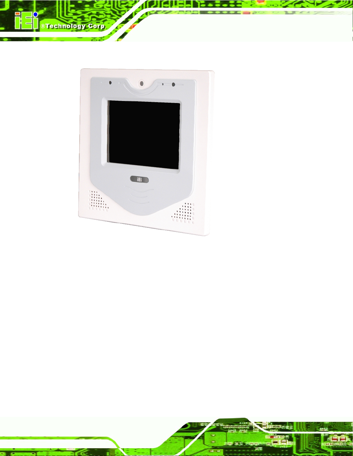
1.1 Introduction
ACT-457A Panel PC
Figure 1-1: ACT-457A
The ACT-457A is an 500 MHz Alchemy AU1250 powered access control terminal with a
RFID reader and a rich variety of functions. The ACT-457A is designed for easy and
simplified integration in to access control applications.
The system comes with 256 MB DDR memory ensuring smooth data throughputs with
reduced bottlenecks and fast system access.
Two serial ports and two external USB 2.0 ports ensure simplified connectivity to a variety
of external peripheral devices. Wi-Fi capabilities and an RJ-45 Ethernet connector ensure
smooth connection of the system to an external network.
1.2 Features
The ACT-457A features the following:
Page 2
5.7" screen with 4-wire resistive type touch screen
Page 11

ACT-457A Panel PC
500 MHz Alchemy AU1250 system processor
Built-in RFID reader supports Mifare card and EM card read/write
256 MB DDR memory preinstalled
802.11 b/g wireless module
One RS-232 port and one RS-232/422/485 port
Two USB 2.0 ports (one on bottom rear I/O and one behind front cover plate)
SD card slot
Provides RFID configuration tool to read or write Mifare tags and EM tags
Built-in digital camera and microphone
Built-in stereo speakers
IP64 compliant front panel
RoHS compliance
1.3 Applications
The ACT-457A is designed for the following applications.
Door access
Time attendance
Cashless payment terminal
Parking access control
Page 3
Page 12
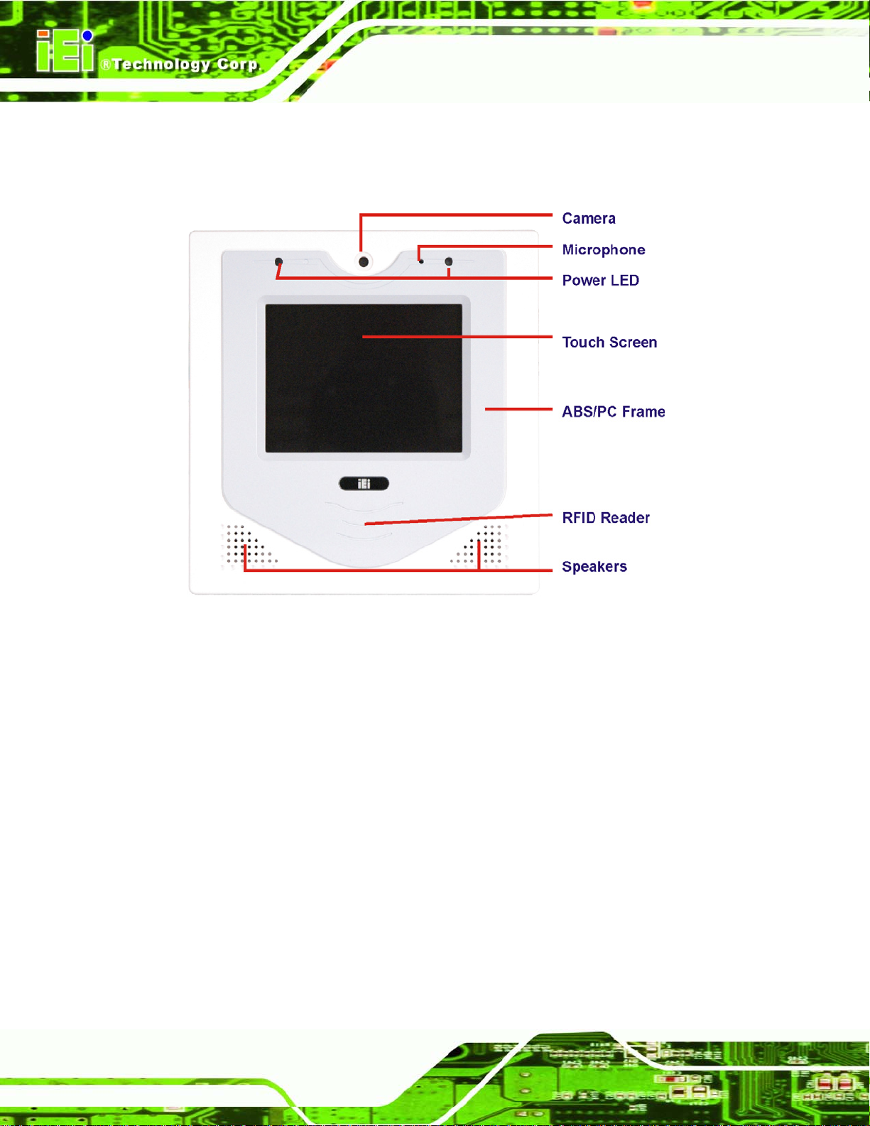
1.4 External Overview
The diagrams below detail all the parts and connectors on the ACT-457A.
ACT-457A Panel PC
Figure 1-2: Front View
Page 4
Page 13
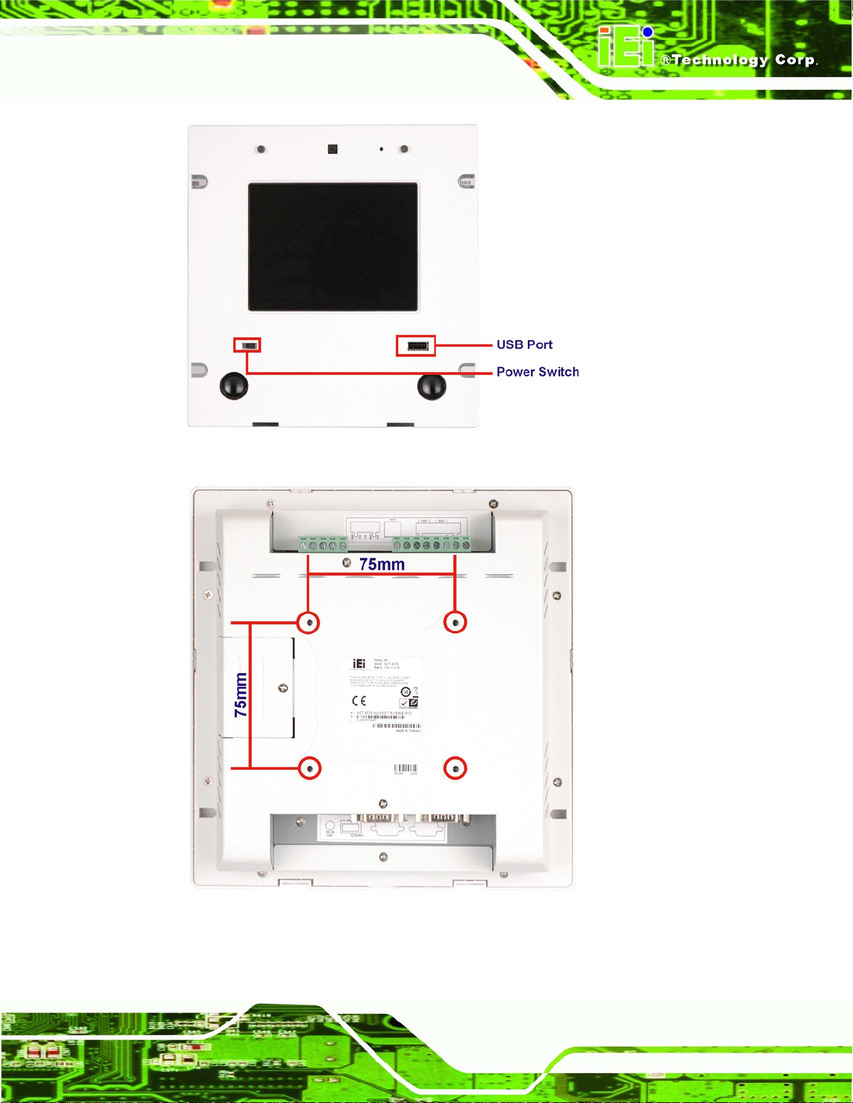
ACT-457A Panel PC
Figure 1-3: Front View (Faceplate Removed)
Figure 1-4: Rear Panel VESA Mounting Holes
Page 5
Page 14
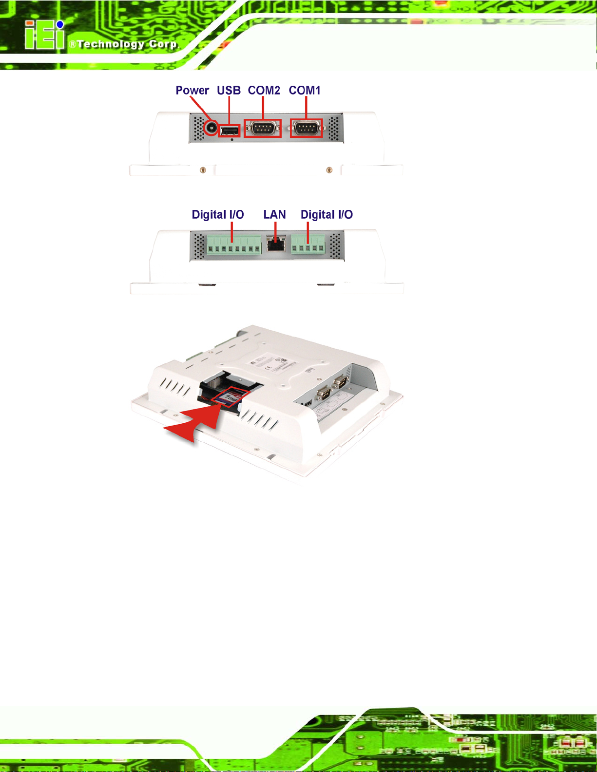
ACT-457A Panel PC
Figure 1-5: Bottom I/O
Figure 1-6: Top I/O
Figure 1-7: CompactFlash® Card Slot
1.5 Internal Parts
The ACT-457A has the following components installed internally:
1 x Motherboard
1 x 1 GB DDR2 SDRAM SO-DIMM
1 x Wireless module
1 x RFID reader
2 x Speakers
1 x Digital camera
Page 6
Page 15
ACT-457A Panel PC
2 x Microphones
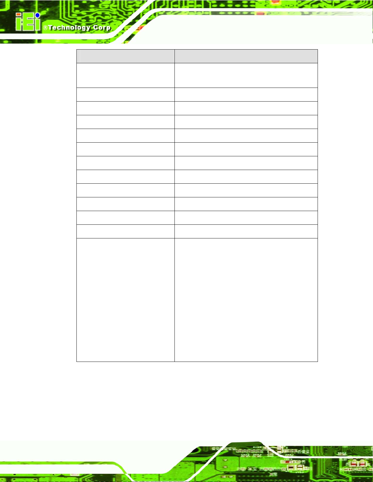
1.6 Specifications
The technical specifications for the ACT-457A system are listed in Table 1-1.
Specification ACT-457A
LCD Size 5.7"
Max. Resolution 640 x 480
Brightness 640 x 480 cd/m2
Contrast Ratio 300:1
LCD Color 262K
Pixel Pitch (mm) 0.06 mm x 0.18 mm
Viewing Angle (H-V) 140/100
Backlight MTBF 25000
SBC Model ACTMB-AU1250-R10
CPU 500 MHz Alchemy AU1250
Memory 1 GB DDR2 SDRAM SO-DIMM (system max. 2
GB)
LAN Two Realtek RTL8111CP PCIe GbE Controllers
SSD CF Type II
HDD One 2.5” SATA HDD bay
Watchdog Timer Software Programmable supports 1 sec. ~ 255
sec. system reset
Audio ALC888 HD Audio codec
AMP 2.0 W + AMP 2.0 W (built-in stereo speakers)
Expansion One PCIe Mini card slot (for wireless LAN 802.11
b/g module)
Camera and MIC Built-in 300 K pixel camera and microphone
RFID Supports MIFARE and EM RFID
Page 7
Page 16
Specification ACT-457A
Construction Material ABS + PC plastic front frame
Aluminum alloy chassis
Front Panel Color Blue and White
Mounting 75 mm x 75 mm
Dimensions (W x H x D) (mm) 207 mm x 214 mm x 44.9 mm
Operation Temperature 0ºC ~ 45ºC
Storage temperature -20ºC ~ 60ºC
Net weight 0.7 kg
IP level (front panel) IP64
Safety & EMC CE / FCC / CB / CCC
Touch Screen 4-wire resistive type
ACT-457A Panel PC
Power input 12 V
Power Consumption 8.5 W
I/O Ports and Switches
(Rear Panel)
Table 1-1: System Specifications
One 12 V DC power jack
One Power switch
One RS-232 COM port
One RS-232/422/485 COM port
One RJ-45 LAN connectors
Two USB 2.0 ports (one under front panel)
One Reset button
Page 8
Page 17
ACT-457A Panel PC
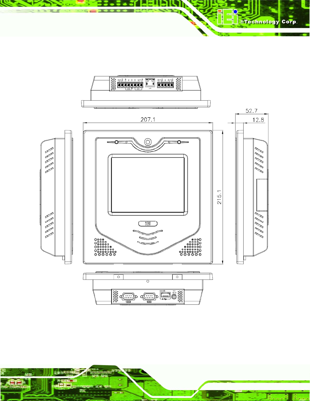
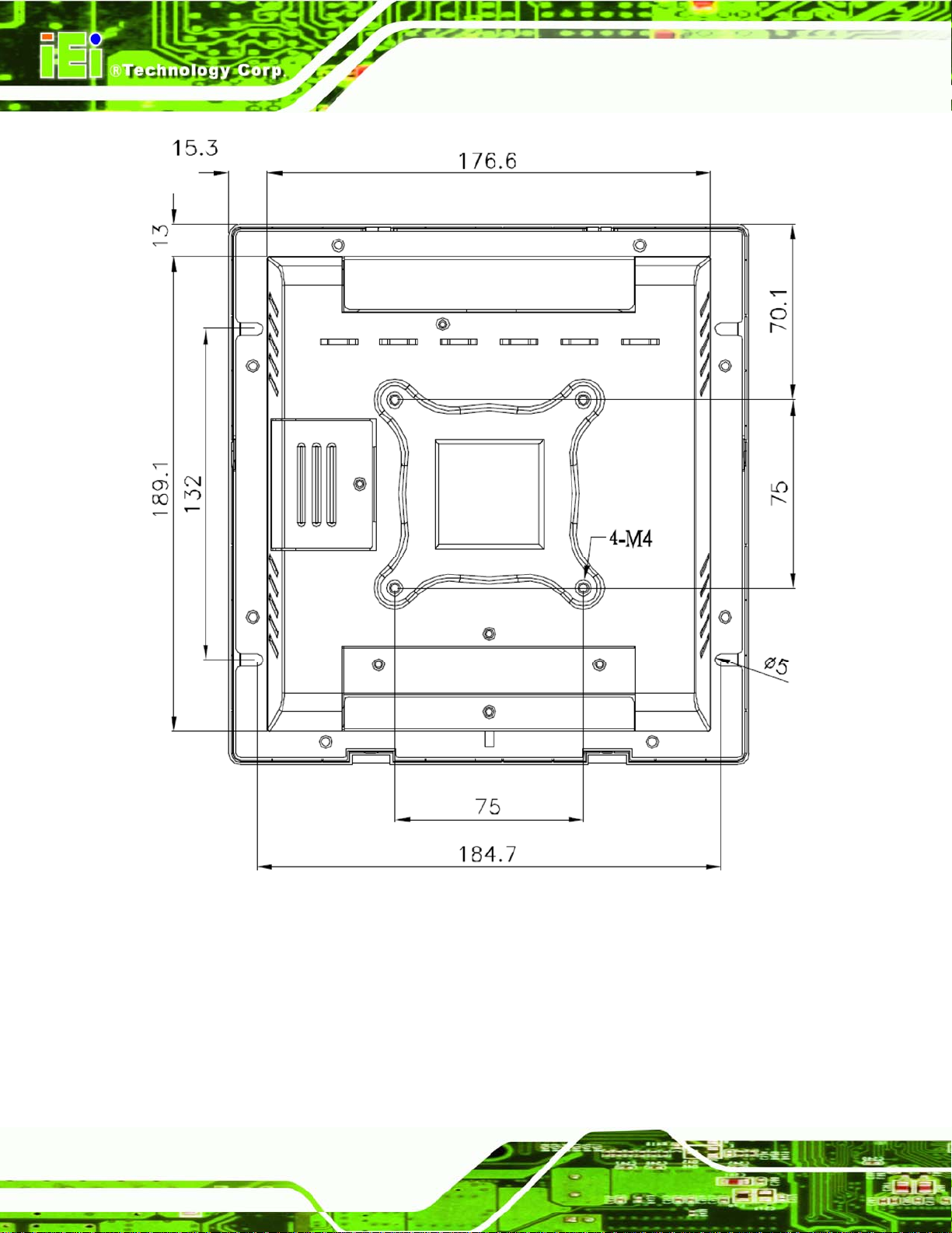
1.7 Dimensions
The dimensions of the ACT-457A are shown below.
Figure 1-8: Front Dimensions
Page 9
Page 18
ACT-457A Panel PC
Page 10
Figure 1-9: Front Dimensions
Page 19

ACT-457A Panel PC
Figure 1-10: Cutout Dimensions
Page 11
Page 20

ACT-457A Panel PC
Chapter
2
2 Installation
Page 12
Page 21

ACT-457A Panel PC
2.1 Unpacking
To unpack the access control terminal, follow the steps below:
WARNING!
The front side LCD screen has a protective plastic cover stuck to the
screen. Only remove the plastic cover after the ACT-457A has been
properly installed. This ensures the screen is protected during the
installation process.
Step 1: Use box cutters, a knife or a sharp pair of scissors that seals the top side of the
external (second) box.
Step 2: Open the external (second) box.
Step 3: Use box cutters, a knife or a sharp pair of scissors that seals the top side of the
internal (first) box.
Step 4: Lift the monitor out of the boxes.
Step 5: Remove both polystyrene ends, one from each side.
Step 6: Pull the plastic cover off the ACT-457A.
Step 7: Make sure all the components listed in the pa cking list are present. Step 0:
Page 13
Page 22

2.2 Packing List
The ACT-457A access control terminal is shipped with the following compone nts:
Quantity Item Image
1 ACT-457A
1 Screw set
ACT-457A Panel PC
1 Power adapter
1 Power cord
1 Touch pen
1 User manual CD and driver CD
1 Mini jumper pack (2.0 mm)
Table 2-1: Packing List
Page 14
If any of these items are missing or damaged, contact the distributor or sales
representative immediately.
Page 23
ACT-457A Panel PC
2.3 Installation and Configuration Steps
The following installation steps must be followed.
Step 1: Unpack the ACT-457A
Step 2: Install SD card (if not pre-installed)
Step 3: Configure the system
Step 4: Connect peripheral devices to the bottom panel of the ACT-457A.
Step 5: Mount the ACT-457A Step 0:
2.4 Rear Panel Removal
To access the jumpers and connectors, the rear panel must be removed.
Step 1: Place the ACT-457A monit or sid e down on a flat surface.
Step 2: Remove the rear panel screws and lift the back cover off. Step 0:
Figure 2-1: Rear Panel Retention Screws
Page 15
Page 24

2.5 SD Card Installation
The ACT-457A has a single SD card slot. To install the SD card, follow the steps below.
Step 1: Locate the SD card cover on the rear panel.
Step 2: Remove the screw and lift the cover off.
ACT-457A Panel PC
Figure 2-2: SD Card Slot Cover Location
Step 3: Insert the SD card into the card slot indicated below .
Figure 2-3: SD Card Installation
Step 4: Put the cover back on. Replace the cover and fasten the screw. Step 0:
Page 16
Page 25

ACT-457A Panel PC
2.6 System Power
The system can be run in the AT power mode or the ATX power mode. Both these power
modes are described below.
2.6.1 ATX Power Mode (Default)
With the ATX mode selected, the ACT-457A panel PC goes in a standby mode when it is
turned off. The panel PC can be easily turned on via network or a power switch in standby
mode. Remote power control is perfect for advertising applications since the
broadcasting time for each panel PC can be set individually and cont rolled remotely . Other
possible application includes
Security surveillance
Point-of-Sale (POS)
Advertising terminal
2.6.2 AT Power Mode
With the AT mode selected, the power is controlled by a central power unit rather than a
power switch. The ACT-457A panel PC turns on automatically when the power is
connected. The AT mode benefits a production line to control multiple panel PCs from a
central management center and other applications including:
ATM
Self-service kiosk
Plant environment monitoring system
Factory automation platform
Manufacturing shop flow
2.7 Mounting the System
The ACT-457A supports the mounting methods shown in the subsections bel ow.
2.7.1 Wall Mounting
To mount the ACT-457A onto the wall, please follow the steps below.
Step 1: Select the location on the wall for the wall-mounting bracket.
Page 17
Page 26

Step 2: Carefully mark the locations of the four screw holes in the bracket on the wall.
Step 3: Drill four pilot holes at the marked locations on the wall for the bracket retention
screws.
Step 4: Align the wall-mounting bracket screw holes with the pilot holes.
Step 5: Secure the mounting-bracket to the wall by inserting the retention screws into
the four pilot holes and tightening them (Figure 2-4).
ACT-457A Panel PC
Figure 2-4: Wall-mounting Bracket
Step 6: Insert the four monitor mounting screws provided in the wall mounting kit into the
four screw holes on the real panel of the ACT-457A and tighten until the screw
shank is secured against the rear panel (Figure 2-5).
Step 7: Align the mou
bracket.
Step 8: Carefully insert the screws through the holes and gently pull the monitor
downwards until the ACT-457A rests securely in the slotted holes (Figure 2-5).
re that all four of the mounting screws fit snuggly into their respective
Ensu
slotted holes.
nting screws on the rear panel with the mounting holes on the
Page 18
Page 27

ACT-457A Panel PC
Figure 2-5: Chassis Support Screws
NOTE:
In the diagram below the bracket is already installed on the wall.
Step 9: Secure the ACT-457A by fastening the retention screw of the wall-mounting
bracket. (Figure 2-6).Step 0:
Page 19
Page 28

ACT-457A Panel PC
Figure 2-6: Secure the ACT-457A
2.7.2 In-wall Mounting
To mount the ACT-457A into a wall follow the directions below.
Step 1: Place the ACT-457A face down on a flat surface.
Page 20
Figure 2-7: Cut Foam Tape
Page 29

ACT-457A Panel PC
Step 2: Cut the adhesive foam tape as shown above.
Figure 2-8: Attach Foam Tape
Step 3: Attach the adhesive foam tape to the edge of rear panel of the ACT-457A (see
Figure 2-8). Make sure the adhesive tape does not cover the screw holes as
hown below.
s
Figure 2-9: Foam Tape Installed
Step 4: Select the position on the wall to mount the flat panel PC.
Page 21
Page 30

Step 5: Cut out hole with the dimensions shown below. Take care that the wall section
that is cut out is no larger than the suggested cut out size.
ACT-457A Panel PC
Figure 2-10: ACT-457A Panel Opening
Step 6: Slide the ACT-457A through the hole until the frame is flush against the wall.
Page 22
Page 31

ACT-457A Panel PC
Step 7: Tighten the screws that pass through the wall mounting screw holes until the
screws are firmly secured to the wall.
Figure 2-11: Tighten the In-wall Mounting Screws
Step 8: Install the faceplate. Snap faceplate onto the ACT-457A frame.Step 0:
Figure 2-12: Faceplate Installation
2.7.3 Arm Mounting
The ACT-457A can be mounted on a VESA compliant 75 mm x 75 mm connector.
Step 1: The arm is a separately purchased item. Please correctly mount the arm onto
the surface it uses as a base. To do this, refer to the installation documentation
that came with the mounting arm.
Page 23
Page 32

ACT-457A Panel PC
NOTE:
When purchasing the arm please ensure it has a 75 mm x 75 mm
mounting hole pattern. Only this mounting size will support the
ACT-457A.
Step 2: Once the mounting arm has been firmly attached to the surface, lift the flat p anel
PC onto the interface pad of the mounting arm.
Step 3: Align the retention screw holes on the mounting arm interface with those in the
flat panel PC. The ACT-457A arm mount retention screw holes are shown in
Figure 2-13.
Page 24
Figure 2-13: ACT-457A Arm Mounting Retention Screw Holes
Step 4: Secure the flat panel PC to the interface pad by inserting four retention screws
through the bottom of the mounting arm interface pad and into the flat panel
Page 33

ACT-457A Panel PC
PC.Step 0:
2.8 Bottom Panel Connectors
Before operating the ACT-457A, connect the peripheral devices listed below.
2.8.1 LAN Connection
There are two external RJ-45 LAN connectors. The RJ-45 connectors enable connection
to an external network. To connect a LAN cable with an RJ-45 connector, please follow
the instructions below.
Step 1: Locate the RJ-45 connectors on the bottom panel of the ACT-457A.
Step 2: Align the connectors. Align the RJ-45 connector on the LAN cable with one of
the RJ-45 connectors on the bottom panel of the ACT-457A. See Figure 2-14.
Figure 2-14: LAN Connection
Step 3: Insert the LAN cable RJ-45 connector. Once aligned, gently insert the LAN
cable RJ-45 connector into the onboard RJ-45 connector. Step 0:
2.8.2 Serial Device Connection
The ACT-457A has two male DB-9 connectors on the bottom panel for serial devices to be
connected. Follow the steps below to connect a serial device to the ACT-457A POS
system.
Page 25
Page 34

Step 1: Locate the DB-9 connector. The location of the DB-9 connector is shown in
Chapter 2.
Step 2: Insert the serial connector. Insert the DB-9 connector of a serial device into
the DB-9 connector on the bottom panel. See Figure 2-15.
ACT-457A Panel PC
Figure 2-15: Serial Device Connector
Step 3: Secure the connector. Secure the serial device connector to the external
interface by tightening the two retention screws on either side of the connector.
2.8.3 USB Device Connection
There are four external USB 2.0 connectors. All connectors are perpendicular to the
ACT-457A. To connect a USB 2.0 or USB 1.1 device, please follow the instructions below.
Step 1: Located the USB connectors. The locations of the USB connectors are shown
in Chapter 2.
Step 2: Align the connectors. Align the USB device connector with one of the
connectors on the bottom panel. See Figure 2-16.
Step 0:
Page 26
Page 35

ACT-457A Panel PC
Figure 2-16: USB Device Connection
Step 3: Insert the device connector. Once aligned, gently insert the USB device
connector into the onboard connector. Step 0:
2.8.4 Digital I/O Installation
WARNING:
1. Power off before wiring
2. Do not connect external power when using the internal 12 V power
3. Do not touch terminals while power is on. Risk of shock
Page 27
Page 36

ACT-457A Panel PC
CAUTION:
1. Digital input
A. The system includes a digital input power source
B. Digital input must be less than 50 VDC
2. Relay output
A. Do not exceed maximum contact capacity, limits listed below
240 VAC @ 10 A
120 VAC @ 12 A
28 VDC @ 10 A
B. Total current consumed by peripherals must be < 1 A
C. Relay signal can affect digital input signal, space cables apart
D. Do not connect peripherals with unknown specifications
E. Do not connect unrated/untested external power supplies
The digital I/O port connects to door sensors and alarms. To connect the wires from the
sensor or alarm to the ACT-457A, follow the directions below.
Step 1: Strip 5 mm of cable housing from the end of the cable.
Step 2: Loosen the screw.
Step 3: Position the cable.
Step 4: Tighten the screw to hold the cable in place. Step 0:
Page 28
Page 37

ACT-457A Panel PC
Figure 2-17: Digital I/O Cable Installation
Page 29
Page 38

ACT-457A Panel PC
Chapter
3
3 RFID Reader
Page 30
Page 39

ACT-457A Panel PC
3.1 Introduction
The RFID tool is used to configure Mifare cards and EM cards.
3.2 Installation
The RF320 RFID application must be installed from the storage card. To install the
software, follow the steps below.
Step 1: Run the installation file at "\\Storage Card\Apps\RF320.exe"
Step 2: To launch the RF320, click Start menu Program File IEI RF320.Step 0:
3.3 RF320 Interface Overview
Figure 3-1: RFID Interface Overview
Label Description
COM Port Settings and Activation Area
Page 31
Page 40

Label Description
Allows the user to select the serial port used by the ACT-457A to
communicate with the RFID reader module.
Commands Area
Shows various request options for user to select.
Data Input Area
The data input area is where the user enters block number, key, key data,
and other information required by certain commands.
Raw Data Display Area
Shows all communication logs and responses of the executed commands.
EM Card ID Display Area
Displays the EM card ID when the EM card is detected.
Mifare Card ID Display Area
Displays the Mifare card ID when the Mifare card is detected.
ACT-457A Panel PC
Error Code Display Area
Shows the error message when an error occurs.
Table 3-1: RFID Interface Overview
3.4 Serial Port (COM) Settings
After launching the RF320 RFID tool, the COM port settings have to be set correctly to
enable the communication with the built-in RFID reader. Please follow the information
below to setup the COM port settings.
Model COM Port Baud Rate
ACT-457A COM 2 19200
Table 3-2: RF320 COM Port Settings
Page 32
Page 41

ACT-457A Panel PC
Figure 3-2: RF320 COM Port Settings
NOTE:
If the Hyper Terminal is used for communication, please setup the port
properties as shown below.
Bits per second: 19200
Data bits: 8
Parity: None
Stop bits: 1
Flow control: None
3.5 RF320 Commands
The RF320 provides five commands, including:
Read Block: read the block data from the Mifare/EM card
Write Block: write the block data into the Mifare/EM card
Set Mifare Parameter
Get Mifare Parameter
Set RF320 Mode
Page 33
Page 42

The following sections describe how to use these commands.
3.5.1 Read Block
To read the block data from a Mifare card, please follow the steps below.
Step 1: Select Read Block in the command area (Figure 3-3).
ACT-457A Panel PC
Step 2: Config
Step 3: Click the Execute b
ure the data, including block, key, key data and time out (Figure 3-3).
port (Figure 3-3).
the format listed in Table 3-3 and Table 3-4. Step 0:
The raw data of this command shows in the Raw Dat a area in
utton to execute the command through the selected serial
Page 34
Figure 3-3: Read Block
Field Command Block KEY KEY Data Time Out End
Digit 2 2 1 12 2 1
Page 43

ACT-457A Panel PC
Field Command Block KEY KEY Data Time Out End
Data RB 00~63 A/B 000000000000
Table 3-3: Read Block Raw Data Format
Status (2 digits) Block Data (32 digits) END (2 digits)
OK 32 bits (Hex) CR,LF (0x0d,0x0a)
ER Error Code (3 digits) CR,LF (0x0d,0x0a)
Table 3-4: Read Block Response Format
3.5.2 Write Block
To write the block data into a Mifare card, please follow the steps below.
Step 1: Select Write Block in the command area (Figure 3-4).
Step 2: Config
00~99
︴(Hex)
FFFFFFFFFFFF
ure the data, including block, key, key data, time out and data
(Second)
CR
(0x0d)
(Figure 3-4).
Step 3: Click the Execute b
port (Figure 3-4).
the format listed in Table 3-5 and Table 3-6. Step 0:
The raw data of this command shows in the Raw Dat a area in
utton to execute the command through the selected serial
Page 35
Page 44

ACT-457A Panel PC
Figure 3-4: Write Block
Field Command Block KEY KEY Data Time Out Block Data End
Digit 2 2 1 12 2 32 1
Data WB 00~63 A/B 000000000000
Table 3-5: Write Block Raw Data Format
Status (2 digits) Block Data END (2 digits)
OK Null CR,LF (0x0d,0x0a)
ER Error Code (3 digits) CR,LF (0x0d,0x0a)
Table 3-6: Write Block Response Format
3.5.3 Set Mifare Parameter
︴(Hex)
FFFFFFFFFFFF
00~99
(Second)
32 digits
Hex
CR
(0x0
d)
Page 36
To set parameter of a Mifare card reader, please follow the steps below.
Step 1: Select Set Mifare Parameter in the command area (Figure 3-5).
Page 45

ACT-457A Panel PC
Step 2: Select a Mifare mode.
0-UUID: read serial number only.
1-UUID & KEY A: read serial number and use "KEY A" to read "Block' data".
2-UUID & KEY B: read serial number and use "KEY B" to read "Block data".
Step 3: Configure the block number, and key data (Figure 3-5).
Step 4: Click the Execute b
port (Figure 3-5).
the format listed in Table 3-7 and Table 3-8. Step 0:
The raw data of this command shows in the Raw Dat a area in
utton to execute the command through the selected serial
Figure 3-5: Set Mifare Parameter
Field Command Access Mode Block KEY Data End
Digit 2 1 2 12 1
Data SM 0~2 00~63 000000000000
︴(Hex)
FFFFFFFFFFFF
Table 3-7: Set Mifare Parameter Raw Data Format
CR (0x0d)
Page 37
Page 46

Status (2 digits) Block Data END (2 digits)
OK Null CR,LF (0x0d,0x0a)
ER Error Code (3 digits) CR,LF (0x0d,0x0a)
Table 3-8: Set Mifare Parameter Response Format
3.5.4 Get Mifare Parameter
To read the parameter of a Mifare card reader, please follow the steps below.
Step 1: Select Get Mifare Parameter in the command area (Figure 3-6).
ACT-457A Panel PC
Step 2: Click the Execute b
port (Figure 3-6).
the format listed in Table 3-9 and Table 3-10. Step 0:
The raw data of this command shows in the Raw Data area in
utton to execute the command through the selected serial
Page 38
Figure 3-6: Get Mifare Parameter
Field Command End
Digit 2 1
Page 47

ACT-457A Panel PC
Field Command End
Data RM CR (0x0d)
Table 3-9: Get Mifare Parameter Raw Data Format
Status (2 digits) Block Data END (2 digits)
OK Access mode (1 digit) +
ER Error Code (3 digits) CR,LF (0x0d,0x0a)
Table 3-10: Get Mifare Parameter Response Format
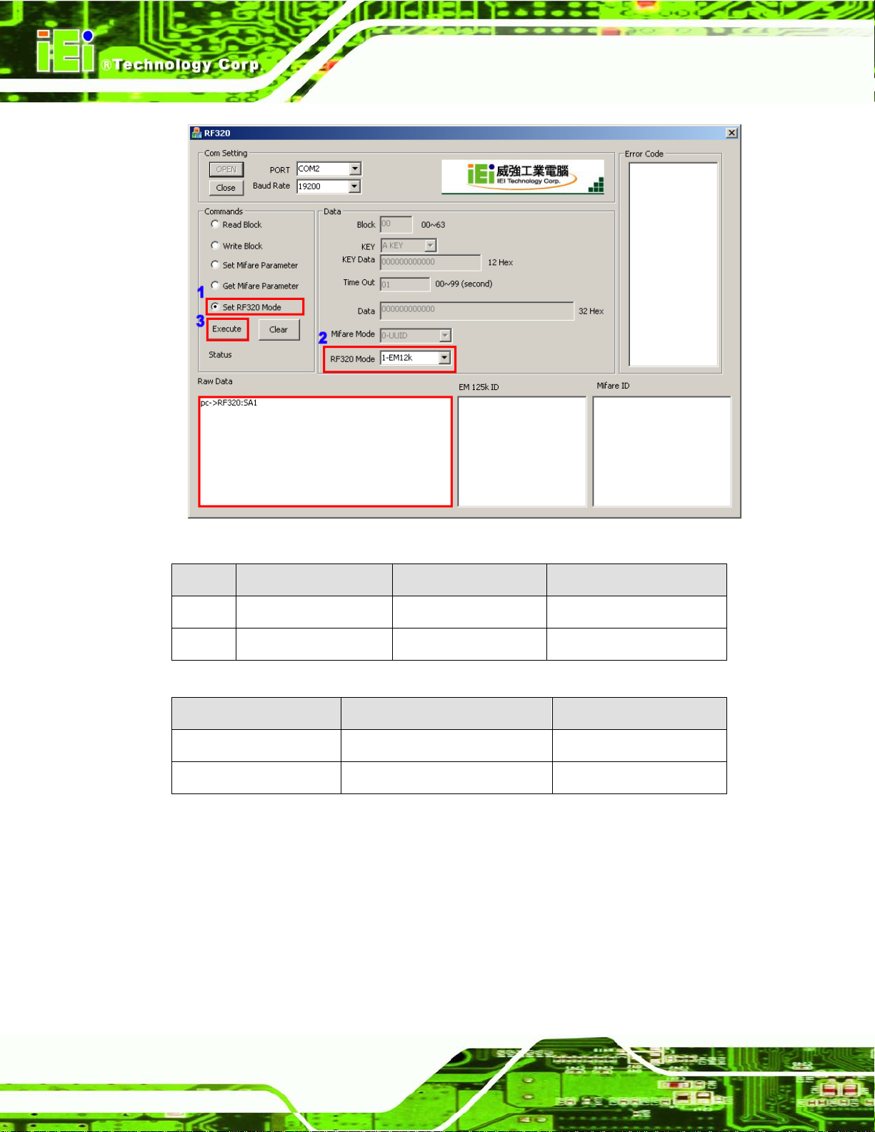
3.5.5 Set RF320 Mode
The Set RF320 Mode command is to set the type of RFID card for the RFID reader to
detect. To set the type of RFID card, please follow the steps below.
Step 1: Select Set RF320 Mode in the command area (Figure 3-7).
Step 2: Select a RF
1-EM12K: detect EM cards only.
CR,LF (0x0d,0x0a)
Block (2 digits) + Mode (1 digit)
320 mode.
2-Mifare: detect Mifare cards only.
3-EM and Mifare: detect both EM and Mifare cards.
Step 3: Click the Execute button to execute the command through the selected serial
port (Figure 3-7).
the format listed in Table 3-11 a
The raw data of this command shows in the Raw Dat a area in
nd Table 3-12. Step 0:
Page 39
Page 48
ACT-457A Panel PC
Figure 3-7: Set RF-320 Mode
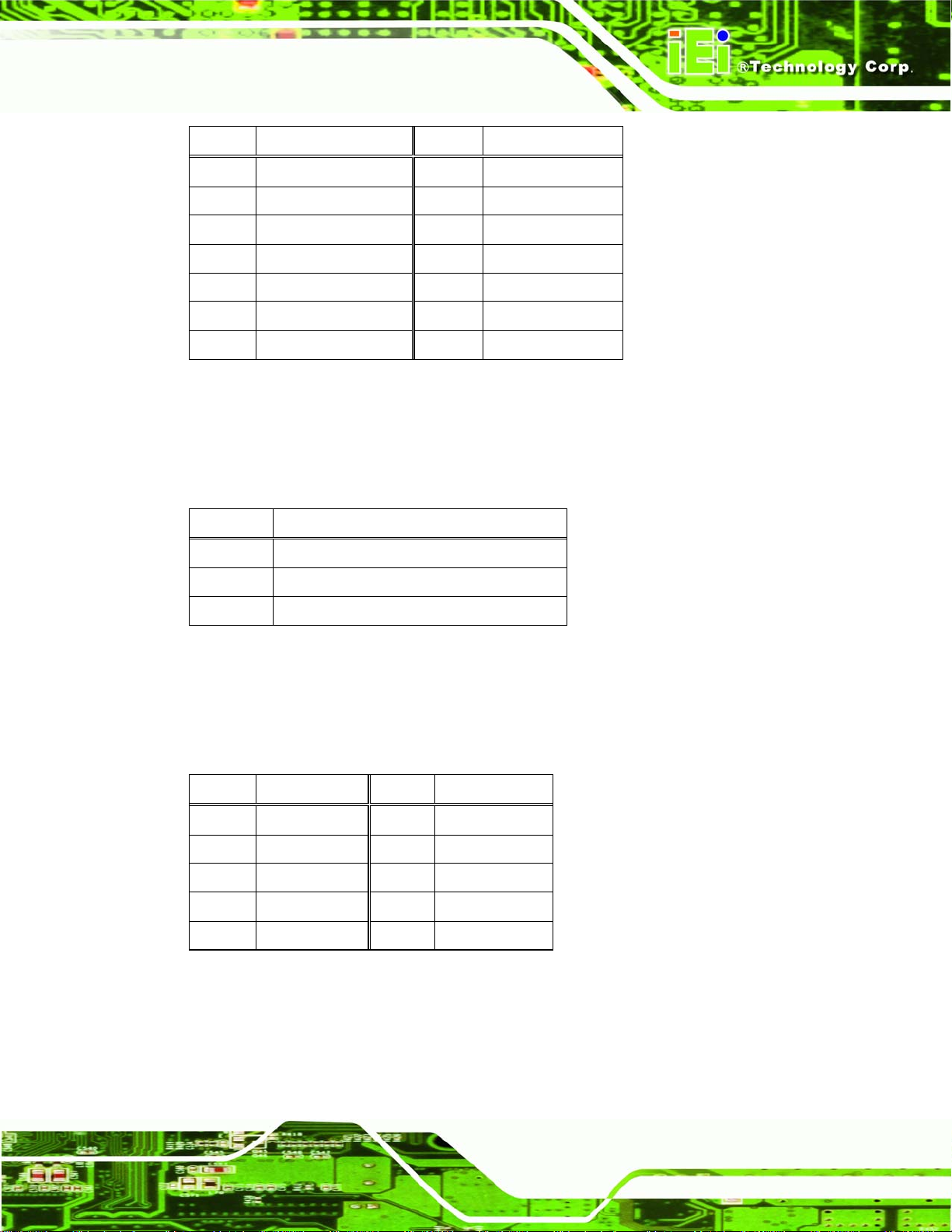
Field Command Mode End
Digit 2 1 1
Data SA 1~3 CR (0x0d)
Table 3-11: Set RF320 Mode Raw Data Format
Status (2 digits) Block Data END (2 digits)
OK Null CR,LF (0x0d,0x0a)
ER Error Code (3 digits) CR,LF (0x0d,0x0a)
Table 3-12: Set RF320 Mode Response Format
Page 40
Page 49

ACT-457A Panel PC
4 System Maintenance
Chapter
4
Page 41
Page 50

4.1 System Maintenance Introduction
If the components of the ACT-457A fail they must be replaced. Components that can be
replaced include:
SD card
Wireless LAN module
SO-DIMM module
Please contact the system reseller or vendor to purchase the replacement parts. Back
cover removal instructions and component replacement for the ACT-457A are described
below.
4.2 Anti-static Precautions
ACT-457A Panel PC
WARNING:
Failure to take ESD precautions during the maintenance of the
ACT-457A may result in permanent damage to the ACT-457A and
severe injury to the user.
Electrostatic discharge (ESD) can cause serious damage to electronic components,
including the ACT-457A. Dry climates are especially susceptible to ESD. It is therefore
critical that whenever the ACT-457A is accessed internally, or any other electrical
component is handled, the following anti-static precautions are strictly adhered to.
Wear an anti-static wristband: Wearing a simple an ti-static wristband can
help to prevent ESD from damaging the board.
Self-grounding: Before handling the board, touch any grounded conducting
material. During the time the board is handled, frequently touch any
conducting materials that are connected to the ground.
Use an anti-static pad: When configuring the ACT-457A, place it on an
Page 42
antic-static pad. This reduces the possibility of ESD damaging the ACT-457A.
Only handle the edges of the PCB: When handling the PCB, hold the PCB
by the edges.
Page 51

ACT-457A Panel PC
4.3 Turn off the Power
WARNING:
Failing to turn off the system before opening it can cause permanent
damage to the system and serious or fatal injury to the user.
Before any maintenance procedures are carried out on the system, make sure the system
is turned off.
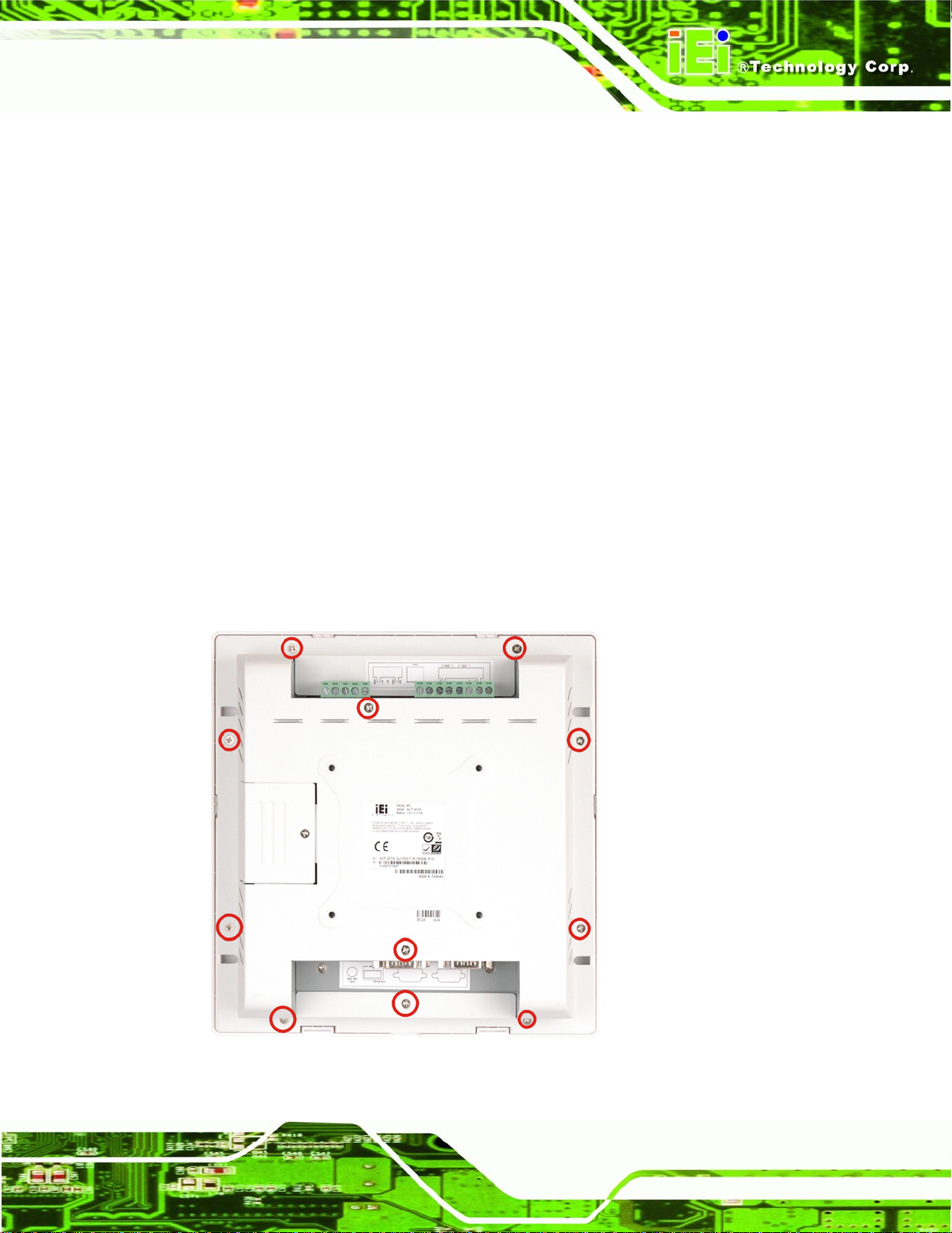
4.4 Rear Panel Removal
To access the jumpers and connectors, the rear panel must be removed.
Step 1: Turn off and disconnect the power from the ACT-457A.
Step 2: Place the ACT-457A monit or sid e down on a flat surface.
Step 3: Remove the rear panel screws and lift the back cover off. Step 0:
Figure 4-1: Rear Panel Retention Screws
Page 43
Page 52

4.5 Replacing Components
The ACT-457A contains no user-serviceable parts. Certain components on the ACT-457A
can be replaced.
4.5.1 SD Card Replacement
The ACT-457A has one CF Type II slot. To replace the CF card, follow the instructions
below.
Step 1: Follow all anti-static procedures. See Section 4.2.
ACT-457A Panel PC
Step 2: T
Step 3: Follow the
urn off the power. See Section 4.3.
steps in the installation section. Step 0:
4.5.2 Motherboard Replacement
A user cannot replace a motherboard. If the motherboard fails it must be shipped back to
IEI to be replaced. If the system motherboard has failed, please contact the system
vendor, reseller or an IEI sales person directly.
Page 44
Page 53

ACT-457A Panel PC
A External Connector
Appendix
A
Pinouts
Page 45
Page 54

A.1 Introduction
Pin out signal definitions for the external connectors are provided in this appendix.
A.2 Digital I/O Connector
The Digital I/O connector on the bottom panel has the following pinouts.
Pin Description
1 VCC
2 GND
3 DO0
4 DO1
5 DI0
6 DI1
ACT-457A Panel PC
Table A-1: Digital I/O Connector Pinouts
A.3 External SATA Connector
The ACT-457A has one external SATA connector on the rear panel.
Pin Description
1 GND
2 TX+
3 TX4 GND
5 RX6 RX+
7 GND
8 GND
9 GND
Table A-2: External SATA Connector Pinouts
A.4 LAN Connector
The ACT-457A has two RJ-45 connectors to provide GbE connectivity.
Page 46
Page 55
ACT-457A Panel PC
Pin Description Pin Description
1 X1+ 2 X13 X2+ 4 X25 VCC2_5 6 GND
7 X3+ 8 X39 X4+ 10 X411 X1- 12 ACT#1
13 LINK1000 LED 14 LINK100 LED
Table A-3: LAN Connector Pinouts
A.5 Power Connector
The power jack on the rear panel of the ACT-457A is a 12 V DC input power connector.
Pin Description
1 12V
2 GND
3 GND
Table A-4: Power Connector Pinouts
A.6 Serial Port Connector (COM1)
The ACT-457A has a DB-9 female connector for connectivity to RS-232 devices.
Pin Description Pin Description
1 DCD1 6 DSR1
2 RX1 7 RTS1
3 TX1 8 CTS1
4 DTR1 9 RI1
5 GND
Table A-5: COM1 Pinouts
A.7 Serial Port Connector (COM3)
The ACT-457A has a DB-9 female connector for RS-232/422/485 devices.
Page 47
Page 56

Pin Description Pin Description
1 DCD3/TX3-/D- 6 DSR3/RX12 RX3/TX3+/D+ 7 RTS3/RX1+
3 TX3 8 CTS3
4 DTR3 9 RI3
5 GND
Table A-6: COM3 Pinouts
A.8 USB Connectors
The ACT-457A has two USB 2.0 connectors.
Pin Description Pin Description
1 USBVCC2 5 USBVCC2
2 D4F- 6 D5F-
ACT-457A Panel PC
3 D4F+ 7 D5F+
4 GND 8 GND
Table A-7: USB1 Connector Pinouts
Page 48
Page 57

ACT-457A Panel PC
Appendix
B
B Terminology
Page 49
Page 58

ACT-457A Panel PC
AC ’97
ACPI
AHCI
ATA
ARMD
ASKIR
BIOS
Audio Codec 97 (AC’97) refers to a codec standard developed by Intel®
in 1997.
Advanced Configuration and Power Interface (ACPI) is an OS-directed
configuration, power management, and thermal management interface.
Advanced Host Controller Interface (AHCI) is a SATA Host controller
register-level interface.
The Advanced Technology Attachment (ATA) interface connects storage
devices including hard disks and CD-ROM drives to a computer.
An ATAPI Removable Media Device (ARMD) is any ATAPI device that
supports removable media, besides CD and DVD drives.
Amplitude Shift Keyed Infrared (ASKIR) is a form of modulation that
represents a digital signal by varying the amplitude (“volume”) of the
signal. A low amplitude signal represents a binary 0, while a high
amplitude signal represents a binary 1.
The Basic Input/Output System (BIOS) is firmware that is first run when
CODEC
CompactFlash®
CMOS
COM
DAC
DDR
the computer is turned on and can be configured by the end user
The Compressor-Decompressor (CODEC) encodes and decodes digital
audio data on the system.
CompactFlash® is a solid-state storage device. CompactFlash® d evices
use flash memory in a standard size enclosure. Type II is thicker than
Type I, but a Type II slot can support both types.
Complimentary metal-oxide-conductor is an integrated circuit used in
chips like static RAM and microprocessors.
COM refers to serial ports. Serial ports offer serial communication to
expansion devices. The serial port on a person al computer is usually a
male DB-9 connector.
The Digital-to-Analog Converter (DAC) converts digital signals to analog
signals.
Double Data Rate refers to a data bus transferri ng data on both the rising
and falling edges of the clock signal.
Page 50
Page 59

ACT-457A Panel PC
DMA
DIMM
DIO
EHCI
EIDE
EIST
Direct Memory Access (DMA) enables some peripheral devices to
bypass the system processor and communicate directly with the system
memory.
Dual Inline Memory Modules are a type of RAM that offer a 64-bit data
bus and have separate electrical contacts on each side of the module.
The digital inputs and digital outputs are general control signals that
control the on/off circuit of external devices or TTL devices. Data can be
read or written to the selected address to enable the DIO functions.
The Enhanced Host Controller Interface (EHCI) specification is a
register-level interface description for USB 2.0 Host Controllers.
Enhanced IDE (EIDE) is a newer IDE interface standard that has dat a
transfer rates between 4.0 MBps and 16.6 MBps.
Enhanced Intel® SpeedStep Technology (EIST) allows users to modify
the power consumption levels and processor performance through
application software. The application software changes the bus-to-core
FSB
GbE
GPIO
HDD
ICH
IrDA
L1 Cache
L2 Cache
frequency ratio and the processor core voltage.
The Front Side Bus (FSB) is the bi-directional communication channel
between the processor and the Northbridge chipset.
Gigabit Ethernet (GbE) is an Ethernet version that transfers data at 1.0
Gbps and complies with the IEEE 802.3-2005 standard.
Gene
ral purpose input
Hard disk drive (HDD) is a type of magnetic, non-volatile computer
storage device that stores digitally encoded data.
The Input/Ouput Controll Hub (ICH) is an Intel® Southbridge chipset.
Infrared Data Association (IrDA) specify infrared data transmission
protocols used to enable electronic devices to wirelessly communicate
with each other.
The Level 1 Cache (L1 Cache) is a small memory cache built into the
system processor.
The Level 2 Cache (L2 Cache) is an external processor memory cache.
Page 51
 Loading...