

IEC Modular Hi-Rise, MPY, MXY, MAY, MBY Ditto Installation, Operation & Maintenance Manual
...Page 1

• Energy
Efficient
• Easy to
Install
• Extended
Service Life
• Energy ecient compact blower coils
• Ideal for educational, hospitality, multi-family, or other commercial environments
• Designed for ducted applications
• Nominal CFM range of 600 to 3,000 CFM
Modular Hi-Rise Series Fan Coils
INSTALLATION, OPERATION, & MAINTENANCE MANUAL
Modular Hi-Rise Models:
MPY, MXY, MAY/MBY Ditto,
MMY/MSY, MUY, and MGY
Page 2
2
2
Modular Hi-Rise Series Fan Coils
INSTALLATION, OPERATION, & MAINTENANCE MANUAL
International Environmental Corporation (IEC) works continually
to improve its products. As a result, the design and specifications
of each product may be changed without notice and may not be
as described herein. Please contact IEC for information regarding
current design and product specifications. Statements and
other information contained herein are not express warranties
and do not form the basis of any bargain between the parties
but are merely IEC’s opinion or commendation of its products.
Manufacturer’s standard limited warranty applies.
Page 3

3
Modular Hi-Rise Series Fan Coils
INSTALLATION, OPERATION, & MAINTENANCE MANUAL
SECTION I – Receipt and Initial Installation
4 Receipt
4 Unpacking and Inspection
5 Handling and Installation
SECTION II – Product Line Specific Installation
5 Part 1 – Universal Hi-Rise Units (MUY)
6 Potential Unit Configurations
6 Unit Knockout Locations (Typical)
7 Supply, Return, and Drain Riser Installation
8 Riser to Unit Installation
8 Riser to Drain Installation
10 Supply Air Installation
10 Part 2 – Ditto and Siamese Ditto ( MAY/MBY)
12 Part 3 – High Rise, Ditto, and Siamese Ditto (MPY, MAY/
MBY, MMY/MSY)
12 Supply, Return, and Drain Risers
13 Part 4 – Mega Mod Units (MGY)
14 Supply, Return, and Drain Risers
14 Riser to Unit Installation
15 Riser to Drain Installation
16 Unit Knockout Locations (Typical)
16 Supply Air Installation
17 Demolition
18 Installation
SECTION III – Finishing Installation (All Models)
18 Grille/Ductwork Installation
18 Outside Air Installation (if required)
18 Electrical Connections
19 Exposed Unit Touch-up and Repainting
19 Concealed Unit Enclosure
SECTION IV – Start-up (All Models)
20 Operating Conditions
20 Cooling/Heating System
20 Air System Balancing
21 Control Board Adjustment
22 Water Treatment
22 Water System Balancing
23 Controls Operation
SECTION V – Routine Maintenance (All Models)
23 Motor/Blower Assembly
23 Coil
24 Electric Resistance Heater Assembly
24 Electrical Wiring and Controls
24 Valves and Piping
24 Filters, Throwaway
25 Filters, Permanent
25 Drain
25 Replacement Parts
SECTION VI – Checklists
25 Receiving and Inspection
25 Handling and Installation
25 Cooling/Heating Connections
25 Ductwork Connections
25 Electrical Connections
26 Unit Start-up
26 Terms and Conditions
Page 4
SECTION I – Receipt and Initial Installation
Receipt
International Environmental Corporation fan coil units
represent a prudent investment oering trouble-free
operation and long service with proper installation,
operation, and regular maintenance.
Your equipment is initially protected under the
manufacturer’s standard warranty; however, this
warranty is provided under the condition that the steps
outlined in this manual for initial inspection, proper
installation, regular periodic maintenance, and everyday
operation of the equipment be followed in detail. This
manual should be fully reviewed in advance before initial
installation, start-up, and any maintenance. Should
any questions arise, please contact your local sales
representative or the factory BEFORE proceeding.
The equipment covered by this manual is available with a
variety of options and accessories. Consult the approved unit
submittals, order acknowledgement, and other manuals for
details on unit options and accessories.
NO ATTEMPT SHOULD BE MADE TO HANDLE, INSTALL,
OR SERVICE ANY UNIT WITHOUT FOLLOWING SAFE
PRACTICES REGARDING MECHANICAL EQUIPMENT.
The equipment must always be properly supported.
Temporary supports used during installation or service
must be adequate to hold the equipment securely.
All power must be disconnected before any installation
or service is attempted. More than one power source
may be supplied to a unit. Power to remote mounted
control devices may not be supplied through the unit.
Never wear bulky or loose tting clothing when working
on any mechanical equipment. Gloves should be worn
for proper protection against heat and other possible
injuries. Safety glasses or goggles should always be
worn when drilling, cutting, or working with chemicals
such as refrigerants or lubricants.
Never pressurize any equipment beyond specied test
pressures. Always pressure test with an inert uid or gas
such as clear water or dry nitrogen to avoid possible
damage or injury in the event of a leak or component
failure during testing.
Always protect adjacent ammable material when
welding or soldering. Use a suitable heat- shield
material to contain sparks or drops of solder. Have a re
extinguisher readily available.
The manufacturer assumes no responsibility for personal
injury or property damage resulting from improper or
unsafe practices during the handling, installation, service, or
operation of any equipment.
Unpacking and Inspection
All units are carefully inspected at the factory throughout
the manufacturing process under a strict detailed quality
assurance program, and, where possible, ALL major
components and sub-assemblies are carefully tested for
proper operation and veried for full compliance with factory
standards. Operational testing of some customer-furnished
components such as electronic control valves and digital
controllers may be a possible exception.
Each unit is carefully packaged for shipment to avoid damage
during normal transit and handling. Equipment should
always be stored in a dry place, and in the proper orientation
as marked on the carton.
All shipments are made F.O.B. factory and is the responsibility
of the receiving party to inspect the equipment upon arrival.
Any obvious damage to the carton and/or its contents should
be recorded on the bill of lading and a claim should be led
with the freight carrier.
After determining the condition of the carton exterior,
carefully remove each unit from the carton and inspect
for hidden damage. At this time, check to make sure that
“furnished only” items such as thermostats, grilles etc. are
accounted for whether packaged separately or shipped at
a later date. Any hidden damage should be recorded and
immediately reported to the carrier and a claim should be
led. In the event a claim for shipping damage is led, the
unit, shipping carton, and all packing must be retained for
physical inspection by the freight carrier. All equipment
should be stored in the factory shipping carton with internal
packing in place until installation.
4
4
Modular Hi-Rise Series Fan Coils
INSTALLATION, OPERATION, & MAINTENANCE MANUAL
Page 5
At the time of receipt, the equipment type and arrangement
should be veried against the order documents. Should
any discrepancy be found, the local sales representative
should be notied immediately so that proper action may
be taken. Should any questions arise concerning warranty
repairs, the factory must be notied BEFORE any corrective
action is taken. Where local repairs or alterations can be
accomplished, the factory must be fully informed of the
extent and expected cost of those repairs before work is
begun. Where factory operations are required, the factory
must be contacted for authorization to return equipment and
a Return Authorization Number will be issued. Unauthorized
return shipments of equipment and shipments not marked
with an authorization number will be refused. In addition,
any claims for unauthorized expenses will not be accepted by
the manufacturer.
Handling and Installation
The units covered in this manual are identied by a tag on
top of the unit which shows the oor and riser number for
which each unit is designed. Units should not be installed at
locations other than that marked on the unit identication
tag. If no specic detail is shown on tag for unit location
then determine conguration for the Universal unit based
on information within this IOM. Should any questions arise
regarding unit conguration, contact the sales representative
or the factory BEFORE proceeding.
While all equipment is designed and fabricated with sturdy
materials and may present a rugged appearance, great care
must be taken to assure that no force or pressure be applied
to the coil, risers, or piping during handling. Never use the
risers to lift the unit. Also, depending on the options and
accessories, some units could contain delicate components
that may be damaged by improper handling. Lifting or
supporting the cabinet only at the top and bottom should
be avoided to maintain the straight and square cabinet
alignment. The unit must be lowered into the space taking
care to properly align the risers to engage the riser swaged
sections on the unit below. The risers should never be bent
or pushed together to be passed through the oor slot and
should never be lifted up or pulled down to meet the risers
on the oor below or above. The risers are designed with a
three-inch swage to accommodate a two-inch overlap and
minor oor to oor variations.
The equipment covered in this manual IS NOT suitable
for outdoor installations. The equipment should never be
stored or installed where it may be subjected to a hostile
environment such as rain, snow, or extreme temperatures.
During and after installation, special care must be taken to
prevent foreign material such as paint, plaster, and drywall
dust from being deposited in the drain pan or on the motor
or blower wheels. Failure to do so may have serious adverse
eects on unit operation, and in the case of the motor and
blower assembly, may result in immediate or premature failure.
All manufacturer’s warranties are void if foreign material is
allowed to be deposited on the motor or blower wheels of any
unit. Some units and/or job conditions may require some form
of temporary covering during construction.
While the manufacturer does not become involved in the
design and selection of support methods and components,
it should be noted that unacceptable system operating
characteristics and/or performance may result from improper
or inadequate unit structural support. Due to variations in
building construction, oor plans, and unit congurations,
each installation is dierent. The actual step-by-step method
of installation may vary from unit to unit. However, the risers
should be moved as little as possible to avoid damage to the
unit and internal components.
On certain units, shipping screws or braces must be removed
after the unit is installed. Be sure to check all tags on the
unit to determine which, if any, of these devices need to be
removed.
5
Modular Hi-Rise Series Fan Coils
INSTALLATION, OPERATION, & MAINTENANCE MANUAL
Page 6
SECTION II – Product Line Specic Installation
Part 1 – Universal Hi-Rise Units (MUY)
The unique design of the Universal Modular Fan Coil unit
allows for eld conguration for each unit. Air discharge,
riser, drain, and outside air knockouts have been strategically
located on each unit. Risers, shown with unit, are for
reference only. All risers are factory fabricated and shipped
loose for eld installation.
It is important that you identify all of the unit feature
locations and which knockouts you intend to use before
proceeding with the installation. Also, it must be determined
whether your application requires a Mating Unit (primary/
secondary) and its conguration. Consult your local sales
representative or the factory for further details on primary/
secondary arrangements.
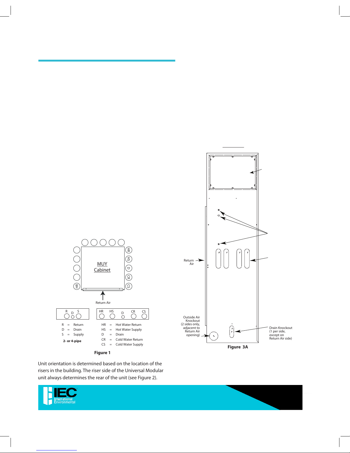
Potential Unit Congurations
Risers: Three Locations–The pre-installed Supply, Return, and
Drain risers (2-pipe or 4-pipe applications) can be oriented on
any of three sides of the unit (see Figure 1).
NOTE: Risers can not be installed on the Return Air side of the
cabinet.
MUY
Cabinet
Return Air
HR CRDHS CS
HR CRDHS CS
HR CRDHS CS
D
CRHSCS
HR
R
D
S
HR = Hot Water Return
HS = Hot Water Supply
D = Drain
CR = Cold Water Return
CS = Cold Water Supply
R = Return
D = Drain
S = Supply
2- or 4-pipe
Figure 1
Unit orientation is determined based on the location of the
risers in the building. The riser side of the Universal Modular
unit always determines the rear of the unit (see Figure 2).
Return Air: Single Location–The Return Air/Access panel
may then be oriented on the left, right, or front of the unit.
Supply Air: Five Locations (4 sides and top) includes
stitched design for 1/2” duct anges.
Outside Air: Two Locations–Either side adjacent to the
Return Air opening.
NOTE: Outside Air opening may not be used on a side if risers are
configured on that same side.
Unit Knockout Locations (Typical)
Side Supply Air
Knockout
(1 per side)
Riser Knockouts
(4 per side,
except on
Return Air side)
Drain Knockout
(1 per side,
except on
Return Air side)
Outside Air
Knockout
(2 sides only,
adjacent to
Return Air
opening)
SIDE VIEW
Return
Air
Optional
Electrical
Knockouts
Figure 3A
6
6
Modular Hi-Rise Series Fan Coils
INSTALLATION, OPERATION, & MAINTENANCE MANUAL
Page 7
Top Supply
Air Knockout
TOP VIEW
Electrical
Knockouts
Figure 3B
Knockout
Slot
Knockout
Tab
KNOCKOUTS:
Knockout
Knockout
Tab
Drain
Knockout
Supply and Return
Figure 4
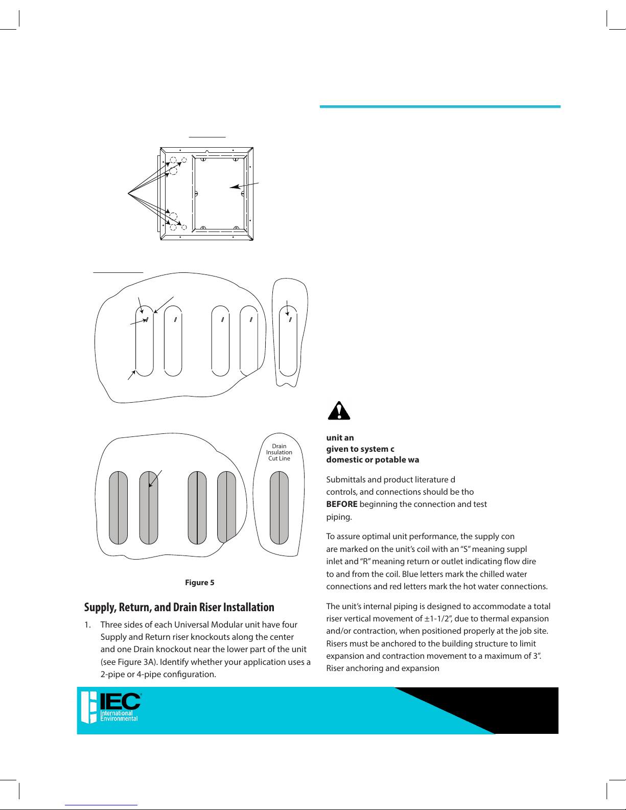
Drain
Insulation
Cut Line
Supply and Return
Insulation Cutline
Figure 5
Supply, Return, and Drain Riser Installation
1. Three sides of each Universal Modular unit have four
Supply and Return riser knockouts along the center
and one Drain knockout near the lower part of the unit
(see Figure 3A). Identify whether your application uses a
2-pipe or 4-pipe conguration.
a. 2-pipe congurations: typically use the two inner
riser knockouts.
b. 4-pipe congurations: will use all four riser
knockouts.
2. Locate and mark the riser and drain knockouts that
apply to your particular unit application, insuring proper
orientation of the Return Air opening in room.
3. Insert a at head screw driver into knockout slot shown in
Figure 4.
4. Pry screw driver back and forth until knockout tabs break
away from the unit.
5. Discard knockout. Be careful of sharp edges.
6. Use a sharp retractable knife (see Figure 5) and vertically
cut the insulation down the center of the riser and drain
knockouts the full length of the knockout.
7. Use adhesive or glue to re-attach insulation that has
pulled away from the unit during knockout removal
process.
CAUTION: Toxic residues and loose particles
resulting from manufacturing and eld piping
techniques such as joint compounds, soldering
ux, and metal shavings may be present in the
unit and the piping system. Special consideration must be
given to system cleanliness when connecting to solar,
domestic or potable water systems.
Submittals and product literature detailing unit operation,
controls, and connections should be thoroughly reviewed
BEFORE beginning the connection and testing of risers and
piping.
To assure optimal unit performance, the supply connection(s)
are marked on the unit’s coil with an “S” meaning supply or
inlet and “R” meaning return or outlet indicating ow direction
to and from the coil. Blue letters mark the chilled water
connections and red letters mark the hot water connections.
The unit’s internal piping is designed to accommodate a total
riser vertical movement of ±1-1/2”, due to thermal expansion
and/or contraction, when positioned properly at the job site.
Risers must be anchored to the building structure to limit
expansion and contraction movement to a maximum of 3”.
Riser anchoring and expansion
7
Modular Hi-Rise Series Fan Coils
INSTALLATION, OPERATION, & MAINTENANCE MANUAL
Page 8
compensation is not included in the unit and must be
provided. Riser end caps, air vents, and/or ushing loops
must be provided at the jobsite by the installer.
Proper eld riser installation and vertical positioning in the
unit should have a pipe run-out to the service valves which
are centered in the knockout access slots and that slope
down slightly away from the riser (see Figure 6). This prevents
condensation from running back to the riser and possible
damage from dripping at the bottom of a riser column.
Each job has specic requirements and satisfying those
requirements is the responsibility of the installer.
Riser to Unit Installation
Ball
Valve
Riser Stubout
Insulation
Threaded
Fitting
Unit insulation
Outer
Cabinet
Riser Knockout
Slot
Figure 6
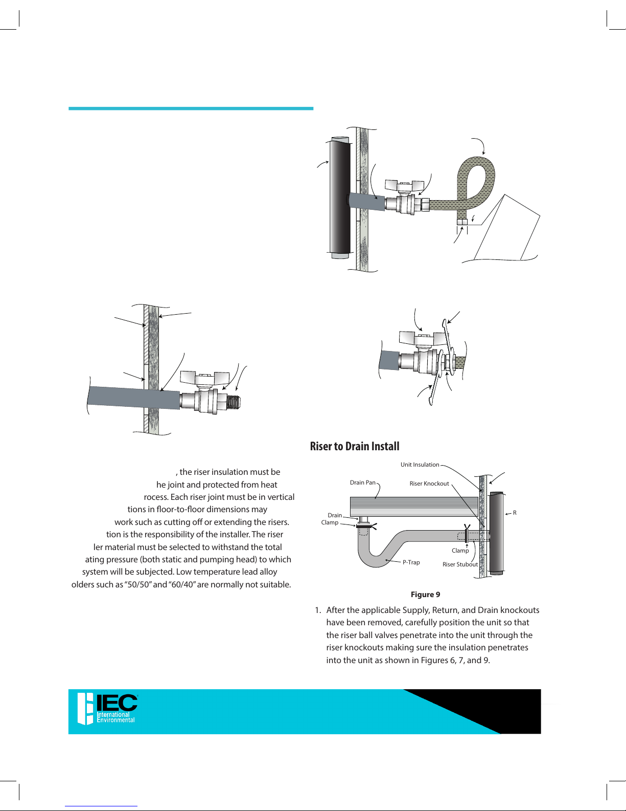
Before making the riser joints, the riser insulation must be
pulled back away from the joint and protected from heat
during the brazing process. Each riser joint must be in vertical
alignment. Variations in oor-to-oor dimensions may
require eld work such as cutting o or extending the risers.
This operation is the responsibility of the installer. The riser
joint ller material must be selected to withstand the total
operating pressure (both static and pumping head) to which
the system will be subjected. Low temperature lead alloy
solders such as “50/50” and “60/40” are normally not suitable.
Flexible
Hose Kit
Riser
Ball
Valve
Riser Stubout
Insulation
Bae
Connection point to any factory
furnished and installed
components.
Coil
Figure 7
Back-up
Wrench
Ball
Valve
Wrench
Swivel
Connection
Figure 8
Riser to Drain Installation
Drain Pan
Drain
Clamp
Clamp
Riser Knockout
Unit Insulation
P-Trap
Unit Wall
Riser
Riser Stubout
Figure 9
1. After the applicable Supply, Return, and Drain knockouts
have been removed, carefully position the unit so that
the riser ball valves penetrate into the unit through the
riser knockouts making sure the insulation penetrates
into the unit as shown in Figures 6, 7, and 9.
8
8
Modular Hi-Rise Series Fan Coils
INSTALLATION, OPERATION, & MAINTENANCE MANUAL
Page 9
2. Before anchoring the equipment in place, the unit must
be leveled and the cabinet must be plumb and squared.
The unit may be anchored in place by bolting directly
through the unit oor or attaching to the cabinet in
some location that will not interfere with drywall or
other items such as the supply grille, thermostat, or
return access panel. When attaching to the unit cabinet,
care must be taken to not penetrate the cabinet in
locations that may damage internal components or
wiring. The mounting technique is a matter of choice;
however, the unit should always be anchored securely
to prevent movement during construction and riser
expansion and contraction.
After anchoring the unit, it is then ready for the various
service connections such as riser connections and
electrical.
3. The plastic are caps on the end of the riser ball valves
should be removed and discarded.
4. All Universal Modular units use reinforced braided
stainless steel exible hose kits for piping between eld
installed risers and unit water coils as shown in Figure 7.
The hose kit design has threaded connections on each
end. The hose kits allow for riser uctuations due to
thermal expansion.
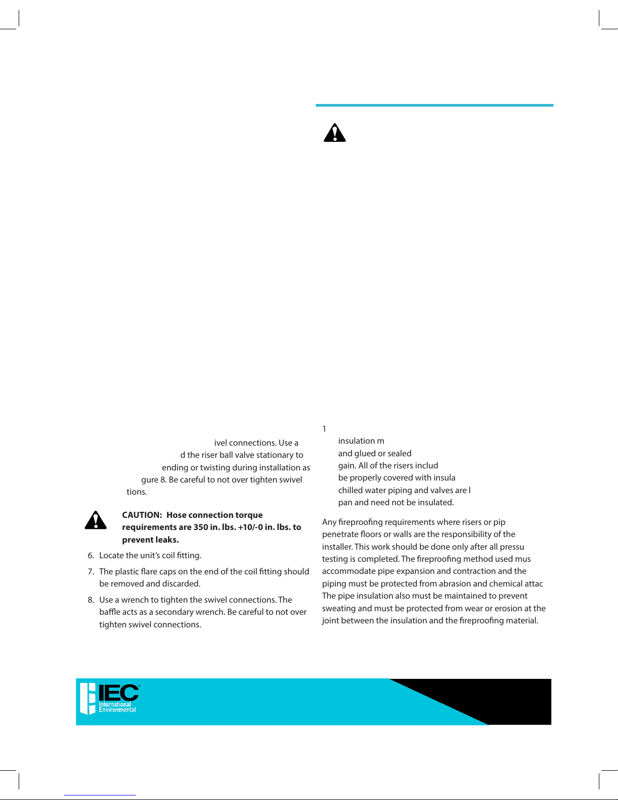
5. Use a wrench to tighten the swivel connections. Use a
backup wrench to hold the riser ball valve stationary to
prevent it from bending or twisting during installation as
shown in Figure 8. Be careful to not over tighten swivel
connections.
CAUTION: Hose connection torque
requirements are 350 in. lbs. +10/-0 in. lbs. to
prevent leaks.
6. Locate the unit’s coil tting.
7. The plastic are caps on the end of the coil tting should
be removed and discarded.
8. Use a wrench to tighten the swivel connections. The
bae acts as a secondary wrench. Be careful to not over
tighten swivel connections.
CAUTION: Hose connection torque
requirements are 350 in. lbs. +10/-0 in. lbs. to
prevent leaks.
9. Locate the p-trap drain and rubber hose factory installed
to the drain pan connection in the bottom of the unit as
shown in Figure 9.
10. Push the rubber drain hose over the riser drain stubout.
Be careful that you do not bend the drain stubout.
11. Adjust the hose clamp over the riser stubout and rubber
hose to hold in place as shown in Figure 9.
12. Test for leaks. Any and all leaks should be repaired before
proceeding with installation. When testing with air or
some other gas, it might be necessary to tighten stem
packing nuts on some valves to maintain air pressure
in the riser. Pressure testing risers with water should
be done with the unit service valves closed to prevent
ushing debris into the unit valve packages. This will
also allow risers to be drained down after testing in
the winter to avoid freeze-up problems. In the event
that leaking or defective components are discovered,
the sales representative must be notied BEFORE any
repairs are attempted. All leaks should be repaired
before proceeding with the unit installation.
13. After system integrity has been established, the riser
insulation must be pulled back into place over the joint
and glued or sealed to prevent sweating and heat loss or
gain. All of the risers including the riser stubouts should
be properly covered with insulation. Internally mounted
chilled water piping and valves are located over the drain
pan and need not be insulated.
Any reproong requirements where risers or piping
penetrate oors or walls are the responsibility of the
installer. This work should be done only after all pressure
testing is completed. The reproong method used must
accommodate pipe expansion and contraction and the
piping must be protected from abrasion and chemical attack.
The pipe insulation also must be maintained to prevent
sweating and must be protected from wear or erosion at the
joint between the insulation and the reproong material.
9
Modular Hi-Rise Series Fan Coils
INSTALLATION, OPERATION, & MAINTENANCE MANUAL
Page 10
When no risers are ordered for the Universal Modular unit,
it is the responsibility of the installer to make sure that an
isolation ball valve is installed between each supply and
return piping connection to the unit. Flare ttings are factory
provided to allow connection between the ball valves and
the hoses.
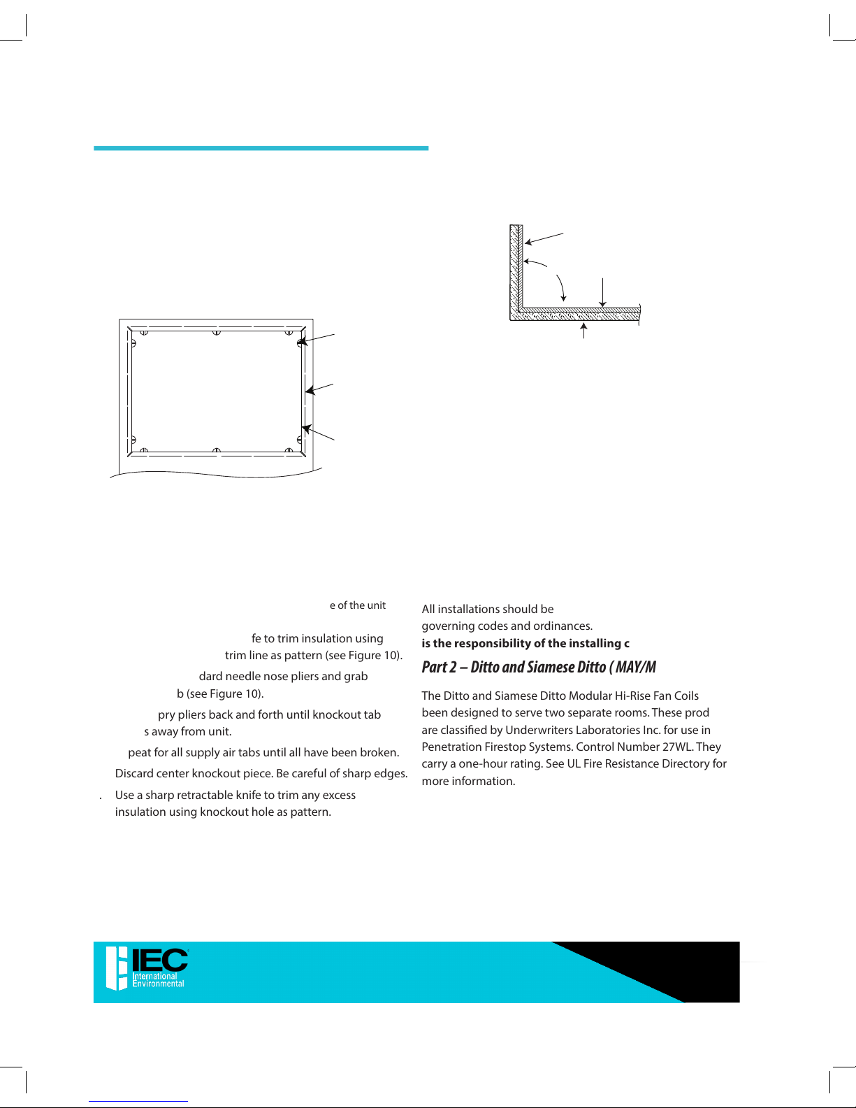
Supply Air Installation
Knockout Tab
(10 places)
Duct Break
(4 places)
Knockout Tab
Trim Line
Figure 10
1. Each side of the unit has one supply air knockout as
well as a supply air knockout on the top of the unit (see
Figures 3A and 3B).
2. Determine which supply air opening/openings are
required for your application.
NOTE: The supply air opening on the riser side of the unit
should not be used.
3. Use a sharp retractable knife to trim insulation using
center knockout slot/trim line as pattern (see Figure10).
4. Use a sharp standard needle nose pliers and grab
knockout tab (see Figure 10).
5. Twist or pry pliers back and forth until knockout tab
breaks away from unit.
6. Repeat for all supply air tabs until all have been broken.
7. Discard center knockout piece. Be careful of sharp edges.
8. Use a sharp retractable knife to trim any excess
insulation using knockout hole as pattern.
Unit
Wall
Unit
Insulation
90°
Duct Flange
Figure 11
9. Use duct pliers (hand seamers) to fold duct ange out of
the unit 90˚ for each side of the supply air opening along
duct break (see Figure 10). The 90˚ anges can now be
used as drywall stops to prevent coverage of discharge
opening (see Figure 11).
10. Use adhesive or glue to re-attach insulation that has
pulled away from the unit during knockout removal
process.
11. For ducted applications tape should be applied along
and around all of the supply air opening knockouts to
prevent air leakage.
All installations should be made in compliance with all
governing codes and ordinances. Compliance with all codes
is the responsibility of the installing contractor.
Part 2 – Ditto and Siamese Ditto ( MAY/MBY)
The Ditto and Siamese Ditto Modular Hi-Rise Fan Coils have
been designed to serve two separate rooms. These products
are classied by Underwriters Laboratories Inc. for use in
Penetration Firestop Systems. Control Number 27WL. They
carry a one-hour rating. See UL Fire Resistance Directory for
more information.
10
10
Modular Hi-Rise Series Fan Coils
INSTALLATION, OPERATION, & MAINTENANCE MANUAL
Page 11

MBY
MAY
Figure 12 – Ditto
MBY
MAY
Figure 13 – Siamese Ditto
The control lines for the drywall track and studs should be
laid out in the oor and ceiling (A) (see Figure 14).
Tracking may be installed now or after the unit is set.
Position the Ditto or Siamese Ditto fan coil assembly
between two rooms with the unit drywall separation spotted
over the wall control lines.
If not already installed, install the oor and ceiling tracks up
to and over the Ditto or Siamese Ditto Fan Coil unit.
Next, position the vertical studs and fasten into each of
the stud pockets formed into the chase side panels (B) (see
Figure 14).
(B) Install wall
stud into
pocket
formed by
chase side
panel
Chase Side Panel
(A) Drywall Track
and Stud
Control Lines
Install studs from top of unit to ceiling (4 corners)
Figure 14 – Unit As Shipped
The studs may be mechanically fastened to the Ditto or
Siamese Ditto Fan Coil. Care should be taken, however, not to
penetrate the supply or return water risers or internal piping.
Given the levelness of the oor and/or the fan coil assembly,
some shimming may be necessary.
Assemble the specied wall construction up to and over the
top of the fan coil unit (C) (see Figure 15).
With the re-wall separation being complete, the drywall
skin on the surface of the individual fan coils can be applied.
Drywall can be applied directly to the surface, or, if necessary,
studding may be installed on the corners for vertical control
(D) (see Figure 15).
For ease of installation of the access panel, apply drywall on
the return air side directly to the surface of the unit (E) (see
Figure 15). When applying the wall board directly to the unit
cabinet, it may be necessary to shim the wall board in some
areas to achieve the desired nished wall surface.
After all drywalling and painting is complete, install
thermostats, supply air grilles and return air panels.
11
Modular Hi-Rise Series Fan Coils
INSTALLATION, OPERATION, & MAINTENANCE MANUAL
Page 12

CAUTION: Avoid penetrating the riser, coil,
piping and electrical system with sheetrock
screws.
Wall Studs
(C) Install wall
gypsum board
(To wall and
over top of unit)
(D) Install gypsum
board to
unit sides
(E) Install
gypsum
board to face
of unit with
cut outs for
supply, return
and thermostat
Figure 15 – On-Site Installation
Part 3 – High Rise, Ditto, and Siamese Ditto (MPY, MAY/
MBY, MMY/MSY)
Supply, Return, and Drain Risers
CAUTION: Toxic residues and loose particles
resulting from manufacturing and eld piping
techniques such as joint compounds,
soldering ux, and metal shavings may be present in the
unit and the piping system. Special consideration must
be given to system cleanliness when connecting to solar,
domestic or potable water systems.
Submittals and product literature detailing unit operation,
controls, and connections should be thoroughly reviewed
BEFORE beginning the connection and testing of risers and
piping.
The supply and return connections are marked on the coil
stub-outs and the valve package with an “S” meaning supply
or inlet and “R” meaning return or outlet indicating ow
direction to and from the coil. Blue letters mark the
chilled water connections and red letters mark the hot water
connections.
The unit internal piping is designed to accommodate a total
riser vertical movement of ±3/4”, due to thermal expansion
and/or contraction, when positioned properly at the job
site. Risers must be anchored to the building structure to
limit expansion and contraction movement to a maximum
of 1-1/2”. Riser anchoring and expansion compensation is
not included in the factory-supplied unit and must be eld
provided. While some special riser features are available from
the factory, riser end caps, air vents, and/or ushing loops are
normally provided on the job by the installer.
Proper riser installation and vertical positioning in the unit
provides for a unit piping run-out to the service valves which
are centered in the access slots and level or sloping down
slightly away from the riser. This prevents condensation
from running back to the riser and possible damage from
dripping at the bottom of a riser column. Each job has
specic requirements and satisfying those requirements is
the responsibility of the installer.
Before making the riser joints, the riser insulation must be
pulled back away from the joint and protected from heat
during the brazing process. Each riser joint must be in vertical
alignment. Variations in oor-to-oor dimensions may
require eld work such as cutting o or extending the risers.
This operation is the responsibility of the installer. The riser
joint ller material must be selected to withstand the total
operating pressure (both static and pumping head) to which
the system will be subjected. Low temperature lead alloy
solders such as “50/50” and “60/40” are normally not suitable.
Chilled water and hot water risers should never be piped
to drain down into the condensate riser. Extensive water
damage can occur due to drain overow. Drain chilled and
hot water risers to a remote location away from the unit such
as sink, room and oor drains.
After the connections are completed, the system should then
be tested for leaks. When testing with air or some other gas,
it might be necessary to tighten stem packing nuts on some
valves to maintain air pressure in the riser. Pressure testing
risers with water should be done with the unit service valves
closed to prevent ushing debris into the unit
12
12
Modular Hi-Rise Series Fan Coils
INSTALLATION, OPERATION, & MAINTENANCE MANUAL
Page 13

valve packages. This will also allow risers to be drained down
after testing in the winter to avoid freeze-up problems.
In the event that leaking or defective components are
discovered, the sales representative must be notied
BEFORE any repairs are attempted. All leaks should be
repaired before proceeding with the installation.
After system integrity has been established, the riser
insulation must be pulled back into place over the joint and
glued or sealed to prevent sweating and heat loss or gain.
Internal chilled water piping and valves are located over the
drain pan and need not be insulated.
Any reproong requirements where risers or piping
penetrate oors or walls are the responsibility of the
installer. This work should be done only after all pressure
testing is completed. The reproong method used must
accommodate pipe expansion and contraction and the
piping must be protected from abrasion and chemical attack.
The pipe insulation also must be maintained to prevent
sweating and must be protected from wear or erosion at the
joint between the insulation and the reproong material.
Before anchoring the equipment in place, the unit must be
leveled and the cabinet must be squared and brought into
line with any adjacent or included walls.
The unit may be anchored in place by bolting directly
through the unit oor or attaching to the cabinet in some
location that will not interfere with drywall or other items
such as the supply grille, thermostat, or return access panel.
When attaching to the unit cabinet, care must be taken to
not penetrate the cabinet in locations that may damage
internal components or wiring. The mounting technique
is a matter of choice; however, the unit should always be
anchored securely to prevent movement during construction
and riser expansion and contraction.
After anchoring the unit, it is then ready for the various
service connections such as riser joints and electrical. At this
time, it should be veried that the proper types of service are
actually provided to the unit. On those units requiring chilled
water and/or hot water, the proper main size and water
temperature should be available to the unit. The electrical
service to the unit should be compared to
the unit nameplate to verify compatibility. The routing and
sizing of all piping, and the type and sizing of all wiring
and other electrical components such as circuit breakers,
service switches, etc. should be determined by the individual
job requirements, and should not be based on the size
and/or type of connection provided on the equipment.
All installations should be made in compliance with all
governing codes and ordinances. Compliance with all
codes is the responsibility of the installing contractor.
Part 4 – Mega Mod Units (MGY)
The unique design of the Mega Modular Fan Coil unit allows
for eld conguration of each unit. Risers, shown with unit,
are for reference only. All risers are factory fabricated and
shipped loose for eld installation.
It is important that you identify all of the unit feature
locations before proceeding with the installation. Also, it
must be determined whether your application requires a
Mating Unit (primary/secondary) and its congurations.
Consult your local sales representative or the factory for
further details on primary/secondary arrangements.
Return Air
MGY 14-20
Cabinet
HR CRDHS CS
HR = Hot Water Return
HS = Hot Water Supply
D = Drain
CR = Cold Water Return
CS = Cold Water Supply
D
CRHSCS
HR
R = Return
D = Drain
S = Supply
R
D
S
2- or 4-pipe
RightLeft
Rear
Front
Figure 16
Unit orientation is determined based on the location of the
risers in the building. Risers can only be installed on the rear
side of the unit and it always determines the rear of the Mega
Mod unit. The return air is always on the front (see Figure 16).
13
Modular Hi-Rise Series Fan Coils
INSTALLATION, OPERATION, & MAINTENANCE MANUAL
Page 14

Supply, Return, and Drain Risers
CAUTION: Toxic residues and loose particles
resulting from manufacturing and eld piping
techniques such as joint compounds, soldering
ux, and metal shavings may be present in the unit and
the piping system. Special consideration must be given
to system cleanliness when connecting to solar,
domestic or potable water systems.
Submittals and product literature detailing unit operation,
controls, and connections should be thoroughly reviewed
BEFORE beginning the connection and testing of risers and
piping.
The supply and return connections are marked on the
coil stub-outs and the valve package depending on your
conguration. “CS” means cold water supply, “CR” means cold
water return, “HS” means hot water supply, and “HR” means
hot water return to indicate ow direction to and from the
coil. Blue letters mark the chilled water connections and red
letters mark the hot water connections.
The unit internal piping is designed to accommodate a total
riser vertical movement of ±1-1/2”, due to thermal expansion
and/or contraction, when positioned properly at the job site.
Risers must be anchored to the building structure to limit
riser expansion and contraction movement to a maximum
of 3”. Riser anchoring and expansion compensation is not
included in the factory-supplied unit and must be eld
provided. While some special riser features are available from
the factory, riser end caps, air vents, and/or ushing loops are
normally provided on the job by the installer.
Proper riser installation and vertical positioning in the unit
provides for a unit piping run-out to the service valves which
are centered in the access slots and level or sloping down
slightly away from the riser. This prevents condensation
from running back to the riser and possible damage from
dripping at the bottom of a riser column. Each job has
specic requirements and satisfying those requirements is
the responsibility of the installer.
Riser to Unit Installation
Ball
Valve
Riser Stubout
Insulation
Threaded
Fitting
Unit insulation
Outer
Cabinet
Riser Knockout
Slot
Figure 17
Flexible
Hose Kit
Riser
Ball
Valve
Riser Stubout
Insulation
Bae
Connection point to any factory
furnished and installed
components.
Coil
Figure 18
Back-up
Wrench
Ball
Valve
Wrench
Swivel
Connection
Figure 19
14
14
Modular Hi-Rise Series Fan Coils
INSTALLATION, OPERATION, & MAINTENANCE MANUAL
Page 15

Riser to Drain Installation
Drain Pan
Drain
Clamp
Clamp
Riser Knockout
Unit Insulation
P-Trap
Unit Wall
Riser
Riser Stubout
Figure 20
1. Carefully position the unit so that the riser ball valves
penetrate into the unit through the riser slot making
sure the insulation penetrates into the unit as shown in
Figures 17 and 18.
2. Before anchoring the equipment in place, the unit must
be leveled and the cabinet must be plumb and squared.
The unit may be anchored in place by bolting directly
through the unit’s oor or attaching to the buildings
walls through the cabinet walls in some location that
will not interfere with drywall or other items such as the
supply grille, thermostat, or return access panel. When
attaching sheetrock to the unit cabinet, care must be
taken to not penetrate the cabinet in locations that may
damage internal components or wiring. The mounting
technique is a matter of choice; however, the unit should
always be anchored securely to the building to prevent
movement during construction and riser expansion and
contraction.
After anchoring the unit, it is then ready for the various
service connections such as riser connections and
electrical.
3. The plastic are caps on the end of the riser ball valves
should be removed and discarded.
4. All Mega Modular units use reinforced braided stainless
steel exible hose kits for piping between eld installed
risers and unit water coils as shown in Figure 18. Each
hose has threaded connections on each end. The hose
kits allow for riser uctuations due to thermal expansion.
5. Use a wrench to tighten the swivel connections. Use a
backup wrench to hold the riser ball valve stationary to
prevent it from bending or twisting during installation as
shown in Figure 19. Be careful to not over tighten swivel
connections.
CAUTION: Hose connection torque
requirements are 350 in. lbs. +10/-0 in. lbs. to
prevent leaks.
6. Locate the unit’s coil tting.
7. The plastic are caps on the end of the coil tting should
be removed and discarded.
8. Use a wrench to tighten the swivel connections. The
bae acts as a secondary wrench. Be careful to not over
tighten swivel connections.
CAUTION: Hose connection torque
requirements are 350 in. lbs. +10/-0 in. lbs. to
prevent leaks.
9. Locate the p-trap drain and rubber hose factory installed
to the drain pan connection in the bottom of the unit as
shown in Figure 20.
10. Push the rubber drain hose over the riser drain stubout.
Be careful that you do not bend the drain stubout.
11. Adjust the hose clamp over the riser stubout and rubber
hose to hold in place as shown in Figure 20.
12. Test for leaks. Any and all leaks should be repaired before
proceeding with installation. When testing with air or
some other gas, it might be necessary to tighten stem
packing nuts on some valves to maintain air pressure
in the riser. Pressure testing risers with water should
be done with the unit service valves closed to prevent
ushing debris into the unit valve packages. These valves
will also allow risers to be drained down after testing
in the winter to avoid freeze-up problems. In the event
that leaking or defective components are discovered,
the sales representative must be notied BEFORE any
repairs are attempted. All leaks should be repaired
before proceeding with the unit installation.
13. After system integrity has been established, the riser
insulation must be pulled back into place over the joint
and glued or sealed to prevent sweating and heat loss
15
Modular Hi-Rise Series Fan Coils
INSTALLATION, OPERATION, & MAINTENANCE MANUAL
Page 16

or gain. All of the risers including the riser stubouts should
be properly covered with insulation. Internally mounted
chilled water piping and valves are located over the drain
pan and need not be insulated.
Any reproong requirements where risers or piping
penetrate oors or walls are the responsibility of the
installer. This work should be done only after all pressure
testing is completed. The reproong method used must
accommodate pipe expansion and contraction and the
piping must be protected from abrasion and chemical attack.
The pipe insulation also must be maintained to prevent
sweating and must be protected from wear or erosion at the
joint between the insulation and the reproong material.
When no risers are ordered for the Mega Modular unit, it is
the responsibility of the installer to make sure that a eld
supplied isolation ball valve is installed between each supply
and return piping connection to the unit. Flare ttings are
factory provided to allow connection between the ball valves
and the hoses.
Variations in oor-to-oor dimensions may require eld work
such as cutting o or extending the risers. This operation is
the responsibility of the installer. The riser joint ller material
must be selected to withstand the total operating pressure
(both static and pumping head) to which the system will be
subjected. Low temperature lead alloy solders such as “50/50”
and “60/40” are normally not suitable.
Chilled water and hot water risers should never be piped
to drain down into the condensate riser. Extensive water
damage can occur due to drain overow. Drain chilled and
hot water risers to a remote location away from the unit such
as sink, room and oor drains.
All installations should be made in compliance with all
governing codes and ordinances. Compliance with all
codes is the responsibility of the installing contractor.
Unit Knockout Locations (Typical)
Side Supply Air
Knockout
(1 per side)
SIDE VIEW
Mega Mod
Cabinet
Optional
Supply
Plenum
Figure 21
Top Supply
Air Knockout
TOP VIEW
Electrical
Knockouts
Figure 22
Supply Air Installation
Knockout Tab
(10 places)
Duct Break
(4 places)
Knockout Tab
Trim Line
Figure 23
16
16
Modular Hi-Rise Series Fan Coils
INSTALLATION, OPERATION, & MAINTENANCE MANUAL
Page 17

1. If the unit has been ordered with a supply air plenum,
then each side of the unit has one supply air knockout as
well as a supply air knockout on the top of the unit (see
Figures 21 and 22).
2. Determine which supply air opening/openings are
required for your application.
NOTE: The supply air opening on the riser side of the unit
should not be used.
3. Use a sharp retractable knife to trim insulation using
center knockout slot/trim line as pattern (see Figure23).
4. Use a sharp standard needle nose pliers and grab
knockout tab (see Figure 23).
5. Twist or pry pliers back and forth until knockout tab
breaks away from unit.
6. Repeat for all supply air tabs until all have been broken.
7. Discard center knockout piece. Be careful of sharp edges.
8. Use a sharp retractable knife to trim any excess
insulation using knockout hole as pattern.
Unit
Wall
Unit
Insulation
90º
Duct Flange
Figure 24
9. Use duct pliers (hand seamers) to fold duct ange out of
the unit 90˚ for each side of the supply air opening along
duct break (see Figure 23). The 90˚ anges can now be
used as drywall stops to prevent coverage of discharge
opening (see Figure 24).
10. Use adhesive or glue to re-attach insulation that has
pulled away from the unit during knockout removal
process.
11. For ducted applications tape should be applied along
and around all of the supply air opening knockouts to
prevent air leakage.
SECTION III – Finishing Installation (All
Models)
Grille/Ductwork Installation
All ductwork and/or supply and return grilles should
be installed in accordance with the project plans and
specications. If not included on the unit or furnished from
the factory, supply and return grilles should be provided as
recommended in the product catalog.
Outside Air Installation (if required)
Units provided with outside air for ventilation should have
some form of low-temperature protection to prevent coil
freeze-up. This protection may be any of several methods
such as a low-temperature thermostat to close the outside air
damper or a preheat coil to temper the outside air before it
reaches the unit.
It should be noted that none of these methods will
adequately protect a coil in the event of power failure.
The safest method of freeze protection is to use glycol in
the proper percent solution for the coldest expected air
temperature.
The manufacturer assumes no responsibility for
undesirable system operation due to improper system
design, equipment or component selection, and/or
installation of ductwork, grilles, and other related
components.
Electrical Connections
The unit serial plate lists the unit electrical characteristics
such as the required supply voltage, fan and heater
amperage and required circuit ampacities. The unit wiring
diagram shows all unit and eld wiring. Since each project
is dierent and each unit on a project may be dierent, the
installer must be familiar with the wiring diagram and serial
plate on the unit BEFORE beginning any wiring.
The unit electrical supply is designed to enter through
knockouts provided in the top of the unit and pass down
through matching knockouts in the control section top.
17
Modular Hi-Rise Series Fan Coils
INSTALLATION, OPERATION, & MAINTENANCE MANUAL
Page 18

Where space allows, power may be pulled directly through
the side of the cabinet into the control section.
All components furnished for eld installation by either the
factory or the controls contractor should be located and
checked for proper function and compatibility. All internal
components should be checked for shipping damage, and
any loose connections should be tightened to minimize
problems during start-up.
Any devices such as fan switches or thermostats that have
been furnished from the factory for eld installation must
be wired in strict accordance with the wiring diagram
that appears on the unit. Failure to do so could result in
personal injury or damage to components, and will void all
manufacturer’s warranties.
The fan motor should never be controlled by any wiring
or device other than the factory-furnished switchor
thermostat/switch combination without factory authorization. Fan motor(s) may be temporarily wired for use
during construction only with prior factory approval in strict
accordance with the instructions issued at that time.
All eld wiring should be done in accordance with governing
codes and ordinances. Any modication of the unit wiring
without factory authorization will void all of the factory
warranties and will nullify any agency listings.
The manufacturer assumes no responsibility for any damages
and/or injuries resulting from improper eld installation and/
or wiring.
Exposed Unit Touch-up and Repainting
Return access and exposed cabinet units may be furnished
with a baked enamel nish. Small scratches in this nish may
be repaired with touch-up paint available from the factory.
Some colors of touch-up paint are available in aerosol
containers and all touch-up paint is available in pint, quart,
and gallon cans. Contact the factory for availability.
Proper safety procedures should be followed regarding
ventilation and safety equipment. The manufacturer’s
directions should be followed for the products being used.
To repaint the factory-baked enamel, the nish should
be prepared by light sanding with #280 grit sand paper
or #000 or #0000 ne steel wool. The surface may also be
wiped with a liquid surface etch cleaning product such as
“No Sand” or “Pasceo.” These items should be available at
most paint product stores. It should be noted that the more
conscientiously this preparation is done, the more eective it
will be.
After this preparation is accomplished, the factory nish
should provide excellent adhesion for a variety of air-dried
top coats. Enamel will give a more durable, higher gloss
nish, while latex will not adhere as well and will give a dull,
softer nish. Top coats involving an exothermic chemical
process between two components, such as epoxies and
urethanes, should be avoided.
Factory aerosol touch-up paint may require a number of light
“dust coats” to isolate the factory-baked enamel nish from
the quick drying touch-up paint.
Concealed Unit Enclosure
Concealed units are designed to have gypsum board or
other types of wall board applied directly to the unit cabinet
surface to a maximum combined thickness of 5/8-inch. The
wall board may be attached with drywall screws or similar
fasteners provided they penetrate the cabinet no more
than 1/2 an inch. These fasteners must be located to avoid
damage to internal components and wiring in the same
manner as the anchoring fasteners. When applying the wall
board directly to the unit cabinet, it may be necessary to
shim the wall board in some areas to achieve the desired
nished wall surface.
An alternate method of enclosing the unit is to frame one
or more sides with studding and apply the wall board to
this framing. This method requires specic unit features and
return access panels when used on the return-air side of a
unit. Units not properly equipped will exhibit poor cooling
and/or heating performance and could experience excessive
or premature component failures.
Contact the sales representative or the factory with any
questions regarding unit enclosure methods.
18
18
Modular Hi-Rise Series Fan Coils
INSTALLATION, OPERATION, & MAINTENANCE MANUAL
Page 19

SECTION IV – Start-up (All Models)
Before beginning any start-up operation, the start-up
personnel should familiarize themselves with the unit,
options and accessories, and control sequence to under stand
the proper system operation. All personnel should have a
good working knowledge of general start-up procedures and
have the appropriate start-up and balancing guides available
for consultation.
The building must be completely nished including doors,
windows, and insulation. All internal walls and doors should
be in place and in the normal position. In some cases the
interior decorations and furniture may inuence overall
system performance. The entire building should be as
complete as possible before beginning any system balancing.
The initial step in any start-up operation should be a nal
visual inspection. All equipment, plenums, duct-work, and
piping should be inspected to verify that all systems are
complete and properly installed and mounted, and that no
debris or foreign articles such as paper or drink cans are left
in the units or other areas.
Each unit should be checked for loose wires, free blower
wheel operation, and loose or missing access panels or doors.
Except as required during start-up and balancing operations,
no fan coil units should be operated without all the proper
ductwork attached, supply and return grilles in place, and all
access doors and panels in place and secure. A clean lter of
the proper size and type must also be installed. Failure to do
so could result in damage to the equipment or building and
furnishings and/or void all manufacturer’s warranties.
Cooling/Heating System
Prior to the water system start-up and balancing, the chilled/
hot water systems should be ushed to clean out dirt and
debris which may have collected in the piping during
construction. During this procedure, the system should be
ushed from the supply riser to the return riser through a
cross-over loop at the end of the riser column, and all unit
service valves must be in the closed position. This prevents
foreign matter from entering the unit and clogging the
valves and metering devices. Strainers should be installed in
the piping mains to prevent this material from entering the
units during normal operation.
During system lling, air venting from the unit is
accomplished by the use of the standard, manual air vent
tting, or the optional, automatic air vent tting installed
on the coil. Venting can be accomplished by depressing the
needle valve core. Automatic air vents may be unscrewed
one turn counterclockwise to speed initial venting, but
should be screwed in for automatic venting after start-up
operations.
CAUTION: The air vent provided on the unit is
not intended to replace the main system air
vents and may not release air trapped in other
parts of the system. Inspect the entire system for
potential air traps and vent those areas as required,
independently. In addition, some systems may require
repeated venting over a period of time to properly
eliminate air from the system.
Air System Balancing
All duct stubs, grilles, lters, and return-access panels must
be properly installed to establish actual system operating
conditions BEFORE beginning air balancing operations.
Each individual unit and the attached ductwork is a unique
system with its own operating characteristics. For this reason,
air balancing is normally done by balance specialists who are
familiar with all procedures required to properly establish
air distribution and fan-system operating conditions.
These procedures should not be attempted by unqualied
personnel.
19
Modular Hi-Rise Series Fan Coils
INSTALLATION, OPERATION, & MAINTENANCE MANUAL
Page 20

Units with no ductwork have air volumes predetermined at
the factory by supply grille size and normally do not require
air balancing other than selecting the desired fan speed.
Units furnished with optional dampers on supply grilles may
require some small adjustments to “ne tune” the air delivery
to each grille. Opposed blade balancing dampers are not
available for all grilles on a unit with electric heat.
After proper system operation is established, the actual unit
air delivery and the actual fan motor amperage draw for
each unit should be recorded in a convenient place for future
reference.
Control Board Adjustment.
Adjusting the Low, Medium and High potentiometer
requires the use of Multi-meter capable of measuring
0~10 VDC.
CAUTION: Only trained and qualied
individuals should attempt to adjust or service
components on any energized electrical equipment.
Failure to follow established safety rules and guidelines
could result in serious injury or death.
When unit is shipped from the factory with motor control
board (which has Hi, Med and Low airow settings), it is pre-
programmed at the factory to “High” speed and delivers the
airow and cooling/heating capacity specied at the time
of order, while Medium and Low Speeds are set to defaults
based on High speed. Should airow require adjustment
after installation, the control board settings for Low, Medium
and High could be adjusted by turning screws(as shown in
the picture) using a small Phillips Screwdriver. It will adjust
the control voltage to the motor. A clockwise rotation
increases the voltage to the motor, while counter clockwise
rotation reduces it.
CAUTION: Both of the procedures described
below require the control box to be powered
while adjustments are made. Line voltage
components are concealed behind a
secondary cover. However, installer should still take all
reasonable precautions.
Unit must be powered to perform the following procedure.
Set the electrical multimeter to VDC (Volts Direct Current).
Attach black negative (-) lead of meter to the terminal
labeled “L2” (shown above the potentiometers).
Attach the RED positive (+) lead of the meter to the terminal
labeled “L1” and conrm that there is approximately 5~10
VDC present.
Attach the RED positive (+) lead of the meter to the DC OUTPUTS. LOW, MED & HIGH are typically connected together.
1. Close either the LOW, MED & HIGH speed relay contacts
by applying 24 VAC to the corresponding LOW, MED or
HIGH 24 VAC INPUT and COM.
2. Measure voltage at the DC OUTPUTS and adjust the
potentiometer for that speed. (VR1 LOW, VR2 MED, VR3
HIGH)
3. In order to achieve higher CFM, turn the potentiometer
Clock-Wise .
NOTE: For specic voltages adjustment please contact IEC
factory representative.
Potentiometer
Low, Med, High CFM adjust
20
20
Modular Hi-Rise Series Fan Coils
INSTALLATION, OPERATION, & MAINTENANCE MANUAL
Page 21

Water Treatment
Proper water treatment is a specialized industry. IEC
recommends consulting an expert in this eld to analyze
the water for compliance with the water quality parameters
listed below, and to specify the appropriate water treatment
regimen. The expert may recommend typical additives such
as rust inhibitors, scaling preventative, antimicrobial growth
agents, or algae preventatives. Anti-freeze solutions may also
be used to lower the freezing point.
IEC water coil tubes and headers are constructed of pure
copper. Multiple brass alloys may be present in the valve
package, depending on unit conguration. It is the user’s
responsibility to ensure the tube and piping materials
furnished by IEC, are compatible with the treated water.
Failure to provide proper water quality may aect the
fan coil unit’s warranty.
Water Containing Required Concentration
Sulphate Less than 200 ppm
pH 7.0 – 8.5
Chlorides Less than 200 ppm
Nitrate Less than 100 ppm
Iron Less than 4.5 mg/l
Ammonia Less than 2.0 mg/l
Manganese Less than 0.1 mg/l
Dissolved Solids Less than 1000 mg/l
CaCO3 Hardness 300 - 500 ppm
CaCO3 Alkalinity 300 - 500 ppm
Particulate Quantity Less than 10 ppm
Particulate Size 800 micron max
Water System Balancing
A complete knowledge of the hydronic system, along with
its components and controls, is essential to proper water
system balancing. This procedure should not be attempted
by unqualied personnel. The system must be complete,
and all components must be in operating condition BEFORE
beginning water system balancing operations.
Each hydronic system has dierent operating characteristics
depending on the devices and controls used in the system.
The actual balancing technique may vary from one system to
another.
After the proper system operation is established, the
appropriate system operating conditions such as various
water temperatures and ow rates should be recorded in a
convenient place for future reference.
Before and during water system balancing, conditions may
exist due to incorrect system pressures which may result in
noticeable water noise or undesired valve operation. After
the entire system is balanced, these conditions will not exist
on properly designed systems.
Controls Operation
Before proper control operation can be veried, all other
systems must be operating properly. The correct water and
air temperatures must be present for the control function
being tested. Some controls and features are designed to
not operate under certain conditions. For example, on a
two-pipe cooling/heating system with auxiliary electric heat,
the electric heater cannot be energized with hot water in the
system.
A wide range of controls, electrical options and accessories
may be used with the equipment covered in this
manual. Consult the approved unit submittals, order
acknowledgements, and other literature for detailed
information regarding each individual unit and its controls.
Since controls and features may vary from one unit to
another, care should be taken to identify the controls used
on each unit and their proper control sequence. Information
provided by component manufacturers regarding
installation, operation, and maintenance of their individual
controls is available upon request.
When changing from one mode to another (cooling to
heating or heating to cooling), it may take some time to
actually notice a change in the leaving air temperature.
In addition, some units may be designed for a very low
air temperature rise in heating. Before declaring a unit
inoperative or a component defective, it may be necessary to
verify operation by more than one method.
21
Modular Hi-Rise Series Fan Coils
INSTALLATION, OPERATION, & MAINTENANCE MANUAL
Page 22

SECTION V – Routine Maintenance (All Models)
Each unit on a job will have its own unique operating
environment and conditions which may dictate a
maintenance schedule that diers from other units on a job.
A formal schedule of regular maintenance and an individual
unit log should be established and maintained. This will help
to achieve the maximum performance and service life of
each unit on the job.
Information regarding safety precautions contained
in the preface at the beginning of this manual should
be followed during any service and maintenance
operations.
For more detailed information concerning service operations
consult your sales representative or the factory.
Motor/Blower Assembly
The type of fan operation is determined by the control
components and their method of wiring. This may vary from
unit to unit. Refer to the wiring diagram that is attached to
each unit for that unit’s individual operating characteristics.
All motors have permanently lubricated bearings. No eld
lubrication is required.
Should the assembly require more extensive service, the
motor/blower assembly may be removed from the unit to
facilitate such operations as motor or blower wheel/housing
replacement, etc.
Dirt and dust should not be allowed to accumulate on the
blower wheel or housing. This can result in an unbalanced
blower wheel condition which can damage a blower
wheel or motor. The wheel and housing may be cleaned
periodically using a vacuum cleaner and a brush taking care
not to dislodge the factory balancing weights on the blower
wheel blades.
Coil
Coils may be cleaned by removing the lter and brushing the
entering air face between ns with a sti brush. Care should
be taken to not damage coil ns. Brushing should be
followed by cleaning with a vacuum cleaner. If a compressed
air source is available, the coil may also be cleaned by
blowing air through the coil ns from the leaving air face.
This should again be followed by vacuuming. Units provided
with the proper type of air lters, replaced regularly, will
require less frequent coil cleaning.
Electric Resistance Heater Assembly
Electric resistance heaters typically require no normal
periodic maintenance when unit air lters are changed
properly. The operation and service life may be aected by
other conditions and equipment in the system. The two
most important operating conditions for an electric heater
are proper air ow and proper supply voltage. High supply
voltage and/or poorly distributed or insucient air ow over
the element will result in element overheating. This condition
may result in the heater cycling on the high-limit thermal
cutout. The high-limit thermal cutout device is a safety device
only and is not intended for continuous operation. With
proper unit application and operation, the high-limit thermal
cutout will not operate. This device only operates when a
problem exists, and ANY condition that causes high-limit
cutout MUST be corrected immediately. High supply voltage
also causes excessive amperage draw and may trip the circuit
breaker or blow the fuses on the incoming power supply.
After proper air ow and supply power are assured, regular
lter maintenance is important to provide clean air over the
heater. Dirt that is allowed to deposit on the heating element
will cause hot spots and eventual element burn through.
These hot spots will normally not be enough to trip the highlimit thermal cutout device and may not be evident until
actual heater element failure.
Electrical Wiring and Controls
The electrical operation of each unit is determined by the
components and wiring of the unit. This may vary from unit to
unit. Consult the wiring diagram attached to the unit for the
actual type and number of controls provided on each unit.
The integrity of all electrical connections should be veried
at least twice during the rst year of operation.
22
22
Modular Hi-Rise Series Fan Coils
INSTALLATION, OPERATION, & MAINTENANCE MANUAL
Page 23

Afterwards, all controls should be inspected regularly for
proper operation. Some components may experience
erratic operation or failure due to age. Wall thermostats
may also become clogged with dust and lint and should
be periodically inspected and cleaned to provide reliable
operation.
When replacing any components such as fuses, contractors,
or relays, use only the exact type, size and voltage
component as furnished from the factory. Any deviation
without factory authorization could result in personal
injury or damage to the unit. This will also void all factory
warranties. All repair work should be done in such a manner
as to maintain the equipment in compliance with governing
codes, ordinances and testing agency listings.
More specic information regarding the use and operating
characteristics of the standard controls oered by the
manufacturer are contained in other manuals.
Valves and Piping
No formal maintenance is required on the valve-package
components most commonly used with fan coil units other
than a visual inspection for possible leaks in the course of
other normal periodic maintenance. In the event that a
valve should need replacement, the same precautions taken
during the initial installation to protect the valve package
from excessive heat should also be used during replacement.
Filters, Throwaway
The type of throwaway lter most commonly used on fan coil
units should be replaced on a regular basis. The time interval
between each replacement should be established based
on regular inspection of the lter and should be recorded
in the log for each unit. Refer to the product catalog for the
recommended lter size for each product type and size. If
the replacement lters are not purchased from the factory,
the lters used should be the same type and size as those
furnished from or recommended by the factory. Pleated
media or extended surface lters should not be used since
the high air pressure drops encountered.
with these types of lters are not compatible with the type
of fan coil unit covered in this manual. Consult the factory for
applications using lter types other than the factory standard
or optional product.
Filters, Permanent
A maintenance schedule for permanent lters should be
developed in the same manner as throwaway lters. Unlike
throwaway lters, permanent lters may be cleaned and
re-installed in the unit instead of being discarded when dirty.
The optional factory permanent lter may be cleaned in hot
soapy water to remove any trapped dirt. It should then be set
aside on edge to dry.
Before replacing the lter in the unit, it should be recharged
with some type of entrapment lm such as “Film-Cor
Recharging Oil.” The lter should be sprayed on both sides
or submerged in the lm to assure complete coverage. The
lter should not be allowed to soak in the lm, but should
be immediately removed and the excess lm drained from
the lter before re-installation in the unit. Consult a local
lter supplier for types of available cleaning solutions and
charging lms.
It should be noted that permanent lters normally have less
static pressure loss than throwaway lters.
Drain
The drain should be checked before initial start-up and at the
beginning of each cooling season to assure that the drain
trap and riser are clear. If it is clogged, steps should be taken
to clear the debris so that condensate will ow easily.
Periodic checks of the drain should be made during the
cooling season to maintain a free-owing condensate.
Should the growth of algae and/or bacteria be a concern,
consult an air conditioning and refrigeration supply
organization familiar with local conditions for chemicals or
other solutions available to control these agents.
23
Modular Hi-Rise Series Fan Coils
INSTALLATION, OPERATION, & MAINTENANCE MANUAL
Page 24

Replacement Parts
Factory replacement parts should be used wherever
possible to maintain unit performance, its normal operating
characteristics, and the testing agency listings. Replacement
parts may be purchased through a local sales representative.
Should replacement parts not be purchased from the factory,
use only parts duplicating the exact type, size, voltage, and
other operating characteristics of the original part.
Contact the local sales representative or the factory before
attempting any unit modications. Any modications not
authorized by the factory could result in personal injury,
damage to the unit, and could void all factory warranties.
When ordering parts, the following information must be
supplied to ensure proper part identication:
(1) Complete unit model number
(2) Unit serial number
(3) Unit hand connection (right or left hand)
(4) Complete part description including any numbers
On warranty replacements, in addition to the information
previously listed, the unit shipping code which appears on
the upper right-hand corner of the serial plate is required.
Contact the factory for authorization to return any parts
such as defective parts replaced in warranty. All shipments
returned to the factory must be marked with a Return
Authorization Number which is provided by the factory.
All equipment and components sold through the Parts
Department are warranted under the same conditions as
the standard manufacturer’s warranty with the exception
that the warranty period is twelve (12) months unless the
component is furnished as a warranty replacement. Parts
furnished as warranty replacements are warranted for the
remaining term of the original unit warranty, or not less than
thirty (30) days.
24
24
Modular Hi-Rise Series Fan Coils
INSTALLATION, OPERATION, & MAINTENANCE MANUAL
Page 25

SECTION VI – Checklists
Receiving and Inspection
Unit received undamaged
Unit received complete as ordered
“Furnish only” parts accounted for
Unit arrangement/hand correct
Unit structural support complete and correct
Handling and Installation
Mounting grommets/isolators used
Unit mounted level and square
Proper access provided for unit and accessories
Proper electrical service provided
Proper overcurrent protection provided
Proper service switch/disconnect provided
Proper chilled water line size to unit
Proper hot water line size to unit
All services to unit in code compliance
All shipping screws and braces removed
Unit protected from dirt and foreign matter
Cooling/Heating Connections
Protect valve package components from heat
Connect eld piping to unit
Pressure test all piping for leaks
Install drain line and traps, as required
Insulate all piping, as required
Connect risers from MM models to MS models
Connect risers to unit coil valve package
(If risers are shipped/installed separately)
Ductwork Connections
Install ductwork, ttings and grilles, as required
Flexible duct connections at unit
Proper supply and return grille type and size
Control outside air for freeze protection
Insulate all ductwork, as required
Electrical Connections
Refer to unit wiring diagram
Connect incoming power service or services
Install and connect “furnish only” parts
Unit Start-up
General visual unit and system inspection
Check for proper fan rotation
Record electrical supply voltage
Check all wiring for secure connections
Close all unit isolation valves
Flush water systems
Fill systems with water/refrigerant
Vent water systems, as required
All ductwork and grilles in place
All unit panels and lters in place
Start fans, pumps, chillers, etc.
Check for overload conditions of all units
Check all ductwork and units for air leaks
Balance water systems, as required
Balance air systems, as required
Record all nal settings for future use
Check piping and ductwall for vibration
Check all dampers for proper operation
Verify proper cooling operation
Verify proper heating operation
Reinstall all covers and access panels
Verify proper condensate drainage
25
Modular Hi-Rise Series Fan Coils
INSTALLATION, OPERATION, & MAINTENANCE MANUAL
Page 26

Forms\IEC\Standard Forms\Word Files\IEC Terms and Conditions 1-Page 09-10.doc
TERMS AND CONDITIONS
1. Orders shall not be binding upon International Environmental Corporation, an Oklahoma
corporation (hereinafter referred to as “IEC”) unless accepted by an authorized representative of
IEC at its office in Oklahoma City, Oklahoma. No distributor, sales representative or any other
person or entity (except authorized e mployees of IEC at its office in Oklahoma City, Oklahoma)
has any authority whatsoever to bind IEC to any representation or agreement of any kind.
2. IEC does not build items to plans and specifications. IEC agrees to furnish only the items as
described in IE C’s acknowledgment unless IEC’s office in Oklahoma City, Oklahoma has
previously received and accepted, in writing, approved submittals from Purchas
er.
3. Prices acknowledged are firm only if Purchaser releases the goods covered by this order for
immediate production by IEC within sixty (60) days from the date of Purchaser’s initial offer to
purchase and for shipment by IEC within IEC’s estimated shipping date, unless otherwise agreed
to in writing by IEC at its office in Oklahoma City, Oklahoma. If Purchaser does not meet the
terms and conditions of this paragraph, the prices are subject to escalation to those prices in effect
at time of shipment without notice to Purchaser.
4. All prices are F.O.B. IEC’s factory, unless otherwise agreed by IEC in writing; and, all payments
and prices shall be in U.S.A. dollars.
5. If goods are released for production but IEC is prevented by the Purchaser from shipping upon
completion or by IEC’s estimated shipping date, whichever is later, IEC may at its option, in
addition to all other remedies, invoice Purchaser to be payable within thirty (30) days and store the
goods at Purchaser’s sole expense.
6. Title to and risk of loss to the goods passes to the Purchaser F.O.B. IEC’s factory.
7. Disclaimer
It is expressly understood that unless a statement is specifically identified as a warranty,
statements made b y IEC or its representatives relating to IEC’s products, whether oral, written or
contained in any sales literature, catalog or any other agreement, are not express warranties and do
not form a part of the basis of the bargain, but are merely IEC’s opinion or co mmendation of
IEC’s products. EXCEPT AS SPECIFICALLY SET FORTH HEREIN, THERE IS NO
EXPRESS WARRANTY AS TO ANY OF IEC’S PRODUCTS. IEC
MAKES NO
WARRANTY AGAINST LATENT DEFECTS. IEC MAKES NO WARRANTY OF
MERCHANTABILITY OF THE GOODS OR OF THE FITNESS OF THE GOODS FOR
ANY PARTICULAR PURPOSE.
8. Grant of Limited Express Warranty
IEC warrants IEC products purchased and retained in the United States of America and Canada to
be free from defects in material and workmanship under normal use and maintenance as follows:
(1) All complete fan coil units built or sold by IEC for twelve (12) months from date of unit start
up or eighteen (18) months from date of shipment (from factory), whichever comes first.
All parts must be returned to IEC’s factory in Oklahoma City, Oklahoma, freight prepaid, no later
than sixty (60) days after the date of the failure of the part; if IEC
determines the part to be
defective and within IEC’s Limited Express Warranty, IEC shall, w hen such part has been either
replaced or repaired, return such to a factory recognized contractor or service organization, F.O.B.
IEC’s factory, Ok lahoma City, Oklahoma, freight prepaid. The warranty on any parts repaired or
replaced under warranty expires at the end of the original warranty period. For information and
warranty service contact:
International Environmental Corporation
Customer Service
5000 West I-40
Oklahoma City, OK 73128
(405) 605-5000
This warranty does not cover and does not apply to: (1) Air filters, fuses, fluids; (2) Products
relocated after initial installation; (3) Any port ion or component of any system that is not supplied
by IEC, regardless of the cause of the failure of such portion or component; (4) Products on
which
the unit identification tags or labels have been removed or defaced; (5) Products on which
payment to IEC is or has been in default; (6) Products which have defects or damage which result
from improper installation, wiring, electrical imbalance characteristics or maintenance; or are
caused by accident, misuse or abuse, fire, flood, alteration or misapplication of the product; (7)
Products which have defects or damage which result from a contaminated or corrosive air or
liquid supply or operation at abnormal temperatures; (8) Mold, fungus or bacteria damages; (9)
Products sub jected to corrosion or abrasion; (10) Products manufactured or supplied by others;
(11) Products which ha ve been subjected to misuse, negligence or accidents; (12) Products which
have been operated in a manner contrary to IEC’s printed in
structions; or (13) Products which
have def ects, damage or insufficient performance as a result of insufficient or incorrect system
design or the improper application of IEC’s products.
IEC is not responsible for: (1) The cost of any fluids or other system components, or associated
labor to repair or replace the same, which is incurred as a result of a defective part covered by
IEC’s Limited Express Warrant y; (2) The costs of labor, materials or service incurred in removal
of the defective part, or in obtaining and replacing the new or repaired part; or, (3) Transportation
costs of the defective part from the installation site to IEC or of the return of any part not covered
by IEC’s Limited Express Warranty.
Limitation:
This Limited Express Warranty is given in lieu of all other warranties. If,
notwithstanding the dis claimers contained herein, it is determined that other warranties exist, any
such warranties, including without limitation any express warranties or any implied warranties of
fitness for particular purpose and merchantability, shall be limited to the duration of the Limited
Express Warranty.
9. Limitation of Remedies
In the event of a breach of the Limited Express Warranty, IEC will only be obligated at IEC’s
option to repair the failed part or unit or to furnish a new or rebuilt part or unit in exchange for the
part or unit which has failed. If after written notice to IEC’ s factory in Oklahoma City, Oklahoma
of each defect, malfunction or other f ailure and a reasonable number of attempts by IEC to correct
the defect, malfunction or other failure and the remed y fails of its essential purpose, IEC shall
refund the purchase price paid to IEC in exchange for the return of the sold good(s). Said refund
shall be the maximum liability of IEC. THIS REMEDY IS THE SOLE AND EXCL USIVE
REMEDY OF THE BUYER OR THEIR PURCHASER AGAINST IEC FOR BREACH OF
CONTRACT, FOR B REACH OF ANY WARRANTY OR FOR IEC’S NEGLIGENCE OR
IN STRICT LIABILITY.
10. Limitation of Liabilit y
IEC shall have no liability for any damages if IEC’s performance is delayed for an y reason or is
prevented to any extent by any event such as, but not limited to: any war, civil unrest, government
restrictions or restraints, strikes, or work stoppages, fire, f lood, accident, shortages of
transportation, fuel, material or labor, acts of God or an y other reason beyond the sole control of
IEC. IEC EXPRESSLY DISCLAIMS AND EXCLUDES ANY LIABILITY FOR
CONSEQUENTIAL OR INCIDENTAL DAMAGE IN CONTRACT, FOR BREACH OF
ANY EXPRESS OR IMPLIED WARR
ANTY, OR IN TORT, WHETHER FOR IEC’s
NEGLIGENCE OR AS STRICT LIABILITY.
11. IEC shall have no system design, application or maintenance responsibility or responsibil ity for
mold, fungus or bacteria to Purchaser or any other third party.
12. All sales, goods and services, use, excise, value added, transportation, privilege, occupational
consumption, storage, document, transaction or other taxes which ma y be levied by any taxing
authority as a result of this transaction shall be paid by the Purchaser.
13. Unless otherw ise agreed to in writing by IEC any technical data furnished in conjunction with this
order and not obtainable from another source shall not be duplicate d, used, or disclosed in whole
or in part for any purpose other than to evaluate this order.
14. IEC shall have no liability or other obligation hereunder, if IEC’s performance is del
ayed for any
reason or is prevented to any extent by any event such as, but not limited to: any act of God, strike
or work stoppage, fire, flood, accident, alloc ation, or other controls of Government authorities,
shortages of transportation, fuel, material or labor, or any other cause beyond IEC’s sole control.
Any shipping d ate stated by IEC is IEC’s best estimate but IEC makes no guarantee of shipment
by any such date and shall have no liability or other obligation for failure to ship on such date,
regardless of cause.
15. Payment terms are net thirty (30) days from date of shipment on approved credit. One and one
half percent (1 1/2%) per month (18% annual rate) may be charged on past due accounts or
the
highest rate permitted by applicable law, whichever is lesser. In the event the account is placed for
collection, Purchaser shall be responsible for all reasonable attorneys fees or costs on a solicitor
and client basis, plus all other costs and expenses incurred by IEC in securing payment.
16. Purchaser shall not cancel the contract without prior written consent of an authorized
representative of IEC at its offices in Oklahoma City, Oklahoma. In the event Purchaser cancels
the contract with the prior written consent of IEC after the Purchaser’s offer to purchase is
received and acknowledged in writing, IEC shall be entitled to receive from Purchaser IEC ’s cost
incurred to time of cancellation plus a reasonable allowance for overhead and profit.
17. Purchaser shall not assign any of its interest or rights under this agreement without written consent
of IEC.
18. IEC will protect all its lien rights. IEC will not furnish lien waivers or releases
until IEC receives
payment, in full, at its office in Oklahoma City, Oklahoma from Purchaser for the goods covered
by this order. There is no authorized retainage for any reason.
19. This Agreement shall be construed, and the rights and liabilities of the parties hereunder shall be
determined in accordance with the laws of the State of Oklahoma. If it shall be found that any
portion of this agreement violates any particular law of the United St ates or any state in the United
States having jurisdict ion or, if applicable, an y law of Canada or any province or territory in
Canada having jurisdiction, such portion of the agreement shall be of no force and effect in that
political unit, division or sub-division in which they are illegal or unenforceable and the
agreement shall
be treated as if such portion or portions had not been inserted. In the event that
any dispute or disagreement in connection with any order should arise or exist between Purchaser
and IEC, jurisdiction and venue for any legal action shall be, if IEC so elects, exclusively in the
state or federal courts in Oklahoma County, Oklahoma. The statute of limitations on any claim of
the Purchaser against the IEC shall be one (1) year from the date the cause of action accrues.
20. Without regard to any other agreement, all obligations of Purchaser to IEC shall become
immediately due and payable if Purchaser becomes insolvent or if Purchaser does not make
payments when due or breaches any other agreement or fails to perform any obligation.
21. All orders are expressly limited and made conditional upon accepta nce b
y Purchaser of the terms
and conditions set forth above without change. There shall be no understandings, agreements, or
obligations (outside these ter ms and conditions) unless specifically set forth in writing and
accepted by signature of an authorized representative of IEC in Oklahoma City, Oklahoma.
22. The parties hereto have requested that these presents and all judicia l proceedings relating thereto
be drafted in English. Les parties aux présentes ont demandé à ce que les présentes et toutes
procedures judiciaires y afférentes soient rédigées en anglais
26
26
Modular Hi-Rise Series Fan Coils
INSTALLATION, OPERATION, & MAINTENANCE MANUAL
Page 27

This page was intentionally left blank.
Page 28
Contact your local IEC Sales Representative for further details and pricing applicable to
this product. Visit our website (iec-okc.com) to nd your local IEC Sales Rep.
IEC Catalog Part #: I100-90001407
IOM-051 Revision 9 (2/2018)
©2015 - 2018 International Environmental Corporation (IEC)
PO Box 2598
Oklahoma City, OK 73101-2598
P: 405.605.5000
F: 405.605.5001
www.iec-okc.com
Modular Hi-Rise Series Fan Coils
INSTALLATION, OPERATION, & MAINTENANCE MANUAL
IEC Modular Hi-Rise IOM Part Number: I100-90001407
IOM-051 Revision 9 (2/2018)
©2015 -2018 International Environmental Corporation (IEC)
 Loading...