

Page 1

IE<:
OPERATION·.··
MANUAL
OM3750
I
Revision 0
I
j .
..
:'.>i
.,
·'
.
'·
..df.11~~
r
-·~UALITY
IEC
CENTRIFUGES
V"Jl.
~~-i~~l~l~::~ge
Cit~
NC)//
~1e1.·
+;
2io~·ii•~
~k-~I.~~~~
9~t.
No.~
..
·.·
•....
·.·
3765
.....
~
2~V~C.
C~tJ
ff:C)~
{
37.6
....
a29,
(;•t•
~o.
37,7
....
aa~tVA(;,
240
VAC,
Cenbifuge
·
60
Hz
j$f)~
240 VAC,
60
Hz
60/60 Hz
50
Hz
IEC
INTERNATIONAL
300 SECOND
TEL.
(781) 449-8060
AVENUE,
EQUIPMENT
NEEDHAM HEIGHTS, MA 02194
•TOLL
FREE (800) 843-1113
COMPANY
U.SA
•FAX
(781) 444-6743
Page 2

1 Introduction
1.1
General Product Description
Centra-CL3 series units are high-speed, multipurpose
centrifuges, used
applications.
The CL3 Series
(Centra-CL3) and refrigerated (Centra-CL3R). Sections
this manual that apply
designated Centra-CL3R
Both units accommodate a wide variety
fixed angle, swinging bucket, and fixed horizontal designs.
They can process tubes, bottles, microplates, microcapillary
tubes, cytological slide carriers, and microsample tubes.
The units can centrifuge up to one liter
operation.
Each centrifuge has an easy to use front panel that provides
two modes
of
operation: Manual and Programmed.
in
medical, industrial, and scientific
is
available in two versions: ventilated
to
the refrigerated version will be
or
refrigerated only.
of
rotors, including
of
fluid in a single
of
f
l
Manual mode
speed/force, and time values for individual runs.
Program mode allows you to define and save a maximum
ninety-nine specific sets
reuse.
Centra-CL3 Series Operation Manual
is
used for entering temperature (CL3R only),
of
run parameters, to recall and
1
of
Page 3
TABLE
OF
CONTENTS
I
t
.Centra-CL3 Series Operation Manual
.Chapter 1: Introduction
1.
1 General Product Description ............................................................................... 1
1.2 About this Manual .............................................................................................. 2
1.3
Warnings, Cautions,
Chapter 2: Installation
2.1
Receiving the Unit .............................................................................................. 5
2.2 Site Preparation .................................................................................................. 5
2.3 Power Configuration ........................................................................................... 7
2.4 Moving the Unit .................................................................................................. 8
2.5 The Front Panel .................................................................................................. 8
. Chapter 3: Operation
3.
1 Rotor and Accessories ......................................................................................
3
.2
Starting and Stopping a Run .............................................................................
3.3 Stored Programs ............................................................................................... 20
3
.4
Centra-CL3 Series Refrigeration .......................................................................
3.
5 Diagnostic Messages and Error Codes ..............................................................
and
Notes ........................................................................... 3
13
17
21
23
Chapter 4: Applications
4.1
Introduction ......................................................................................................
4.2 Speed and Force Tables .................................................................................... 27
4.3
Derating for Dense Samples Table ....................................................................
4.4 Chemical Resistance Table ................................................................................ 39
4.5 Decontamination Table ..................................................................................... 40
4.6 RCF Nomograph ..............................................................................................
Chapter
5.1
5.2 Care and Cleaning .............................................................................................
5.3
5.4 Condition
5.5
Chapter 6: Specifications
Unit Specifications ................................................................................................... 49
5:
Maintenance
Introduction ......................................................................................................
Cover Interlock Bypass Switch ......................................................................... 46
of
Returned Equipment ..................................................................... 47
Warranty ........................................................................................................... 47
Centra-CL3 Series
Operation
I
Manual
25
36
41
43
43
Page 4
,!
..
~·,
. "
. t
The CL3 Series features a maintenance-free, brushless
motor, and an easy-to-use front panel, which provides three
versatile timing modes: automatic timed run, momentary
spin, and continuous operation (hold mode). Acceleration
and brake rates may be controlled,
for fast separations or slow for delicate samples. Repeat
runs, with the same speed and time settings, may be
achieved at the touch
A fail-safe cover interlock insures that
before a run can begin, and keeps the cover closed, until the
rotor has reached a safe low speed (below 100 rpm), even in
the event
The rugged steel cabinet and rigid construction provide
quiet operation and long term reliability.
1.2 About This Manual
of
a power failure.
of a key.
to
optimize runs: rapid
the
cover is closed,
!
;
I
The Operations Manual contains all
needed to install, operate, and maintain a CL3 Series
centrifuge. Refrigerated and ventilated models operate
similarly, and any differences are highlighted and noted,
throughout this manual. This manual, also, contains speed
and force, derating, chemical resistance, and
decontamination tables. The last chapter lists the units'
specifications.
This manual
to operation information, it contains a few basic
troubleshooting techniques, and a chapter on maintenance.
This Operation Manual
centrifuge units.
is
written for centrifuge operators. In addition
is
not a guide for servicing
of
the
information
Centra-CL3 Series Operation Manual
2
Page 5

1.3 Warnings, Cautions, and Notes
The tenns warning, caution, and
in
meanings
Warning
• A
that could result
Caution
• A
this manual.
advises against certain actions
in
personal injury.
advises against actions
note
have specific
or
or
situations
situations that
could damage equipment, produce inaccurate data, or
invalidate a procedure.
• A Note provides useful infonnation regarding an
operation, function,
or
procedure.
Centra-CL3 Series Operation Manual
3
Page 6

- !
t
-
2.1
Receiving the Unit
International Equipment Company (IEC) ships the
centrifuge
Follow the unpacking instructions on the carton.
complete and return the postage-paid warranty card.
2 Installation
in
a carton that protects it from shipping hazards.
Be
sure
to
2.2
·
Site Preparation
The unit normally resides on a bench top. The Centra-CL3
in
(ventilated model) can be placed
than 0°C), for processing temperature-sensitive samples.
When you remove the centrifuge from a cold environment,
do not operate for a minimum
condensation will evaporate.
Note: When used
noise may become evident. The bearing lubricant thickens
at low temperatures.
thinned and distributed more evenly. Once this occurs, any
noise should subside.
in
a cold room environment, some bearing
As
the centrifuge speeds up, it
a cold room (no colder
of
two hours, so that any
is
Centra-CL3 Series Operation Manual
s
Page 7

The following table lists the physical dimensions for
Centra-CL3 and Centra-CL3R:
the
CL3R
Sample
Cover
Cover
Width
Depth
A clearance
side
centrifuge on a clean, dry surface,
suction feet at the
area beneath the unit free
The resting surface must
free operation.
improperly loaded centrifuge may vibrate
Closed
Open
of
the unit,
Loading
Height
Height
Height
of
8 cm (3 inches) should
to
ensure proper ventilation. Place
bottom
A rigid and stable location is important. An
12.5" (32 cm) 12.5" (32 cm)
14.5" (37 cm) 14.5" (37 cm)
33" (84 cm)
26.5" (68 cm) 19.25" (49 cm)
21" (53 cm) 21" (53 cm)
be
to
make certain that
grip the surface firmly. Keep
of
debris and loose materials.
be
level,
to
ensure quiet, vibration-
CL3
33" (84 cm)
provided on each
the
the
the
or
move.
~al"Jling;·.•1nternationa1••~lectrot~(;hnlcal
~t3#4?rcf•i<no••part;·g¢20•A#rlt8••th~
••
G<)nunission•.
pe~tie<l••rti()velJleJ1~•
•
<>fa.•fabol"atc>&·•ce11trifUge••t()•$QQ~H@IP)iri·the••uillikely
•:JZQ~ai;e~~~~~t~~1;~~;~~rl~~i~~sP~1i:!~zs•.
eriier•\ViiliiJit~•·bqun(iaw.W-lii~~
tp~
petit#fuge
qperat~s.
Centra-CL3
Series
Operation
6
Manual
Page 8
2.3
Power Configuration
Power Cord
The CL3 Series uses
appropriate for use throughout the world. Please check
catalog number
ensure that the machine you have is the proper power
configuration. For best results, the refrigerated centrifuge,
Centra-CL3R, should be used
Variations in line voltage
speed and other characteristics. Less than nominal line
voltage may prevent the centrifuge from reaching maximum
published specifications
Power line voltage, at some locations, may sag, when
refrigeration system turns on.
The unit requires a grounded power supply
If
outlet).
outlets, arrange for a proper grounding. The power
plugs in on the left rear side
your facility does not have grounded
AC
power in different configurations,
of
the model that you have purchased,
on
a dedicated line.
or
frequency affect the
of
speed and/or temperature.
(3
prong
of
the unit.
the
to
unit's
the
power
cord
~=~o~=:i:ili~~~t~~~e
power plug tbatdoes not
have
~
gr~Undilig
pin.
··
·.···
· ·
Circuit Breaker
The
power
highest
interchanged
demand.
createa
The system provides
emergency situations, such as power surges, that could
damage the unit.
If
the circuit breaker trips:
1.
Unplug the unit.
2.
Press the white button, on the left side
3.
Plug the unit back
cord
current
with
Exchange
fire
hazard.
provided with the tiJlltiscorrectly rated
demand.
cords
of
This
poweirord.shouldJ1ot
from
equipinentwitb.Jower current
power
cords
befiVeell
an
automatic circuit breaker, for
in.
equipment•may
of
the unit.
be
forthe
Centra-CL3 Series Operation Manual
7
Page 9

2.4 Moving the Unit
Suction cups, at the bottom
the work surface. Keeping the unit stationary is a safety
feature.
To move the unit to a new location:
1.
Check that the new site meets the criteria
2.2., before moving the unit.
2.
Position a flat object, such as a tongue depressor, near a
suction cup at the bottom
3.
Lift up
enough to break the vacuum seal.
4.
When
work surface.
an
edge
of
all
four cups are disengaged, lift the unit from the
Caution: When the unit
the suction cups adhere correctly to the work surface.
of
the unit, keep it anchored
in
Section
of
the unit.
the cup, and insert the flat object far
is
in
its new location, ensure that
to
2.5 The Front Panel
©
The Front Control Panel
(Centra-CL3R)
Centra-CL3
Series
Operation
8
Manual
Page 10

©
On/Off
use
control panel and refiigeration system (Refrigerated model
only). The
Stop a run with the
display chamber temperature whenever they are plugged in,
but will not cool down
light indicates that the centrifuge is plugged
key:
The On/Off key must be activated,
of
the front panel. This key applies power
On/Off key is inoperative during actual runs.
STOP key. Refrigerated models
if
the unit
is
off
to
enable
to
the
The red STOP
in.
The control panel contains numeric displays for
(Speed/Force), Time, and Temperature (Refrigerated only).
These displays have
display) and Set (dim display).
In Actual mode (bright display), they indicate current run
conditions, such as:
• rotor speed
• elapsed time of,
• actual temperature (Refrigerated only).
In Set mode (dim display), the display indicates the desired
settings for the run. Set mode
• whenever you use the up and down arrows
• briefly, at the start
• briefly, after the unit
The display
The display
numeric displays can, also, display warning
messages (see Section 3 .5). Descriptions
appear on the following pages.
is
is
two
states
or
force
or
time remaining
of
is
bright, when it shows Actual run conditions.
dim, when it shows Set parameters.
or
modes: Actual (bright
is
operative:
a run
switched ON
in,
the run
RPM/RCF
or
error
of
the displays
The
Centra-CL3 Series Operation Manual
9
Page 11

0
Speed/Force display: The number in the speed/force
rotor
speed
display (above this symbol) represents the
RPM
or
force in RCF. Press this symbol
RPM
and RCF. When
indicates revolutions per minute. When
the display indicates relative centrifugal force.
to
arrow keys
shows speed within 50 RPM. It never requires calibration.
Select speed in increments
through 8,500 RPM. Select RCF in increments from
1 - 1,000 xg by 50 xg and above 1,000 xg by 100 xg. The
numeric display can, also, display warning
messages (see Section 3.5).
change the set speed
RPM
is selected, the display
of
100 RPM, from 1,000
or
to
toggle between
RCF
is selected,
force.
or
The
error
Use
in
the
display
Time display: The number
symbol) indicates time. Below ten minutes, time is
displayed as minutes:seconds. Above ten minutes,
minutes are displayed.
Time is set
• 1 second increments, from 1 15
•
• 1 minute increments, from 5 - 99 minutes.
In normal timed mode, the system counts
point. In time
counts up.
In At-Start mode, the timer begins counting
run. In At-Speed mode, the timer begins counting when the
rotor
Temperature display: The number
this symbol) represents temperature
from - 9 °C
in:
second increments, from 1 - 5 minutes.
Hold
or
reaches
95%
of
through+
in
the display (above this
59
seconds.
down
momentary spin modes,
at
the set speed.
in
the display (above
in
degrees Celsius,
40 °C (Refrigerated only).
just
from the set
the
system
the
start
of
a
Centra-CL3 Series Operation Manual
10
:I
Page 12

Program
key: This key saves the currently displayed
desired settings as stored programs I through 99 (see
Section 3.3). The numeric display (above this symbol)
shows the stored program number and mode
of
operation
(see Section 3 .2).
Rotor/Radius
indicates the selected rotor number
Key: The display (above this symbol)
or
the
rotor radius,
in
centimeters. The rotor/radius key toggles between the two
displays. The applicable IEC rotor numbers are supplied
in
the memory, along with their maximum radii, in
centimeters. To select a rotor number, toggle
to
ROTOR,
and press an arrow key under the rotor/radius display. To
change the radius, toggle to RADIUS, and press an arrow
Note
key under the rotor/radius display.
that the radius
cannot be changed to a radius larger than the maximum
radius,
or
less than the minimum radius, for the selected
rotor.
Use the arrow keys to view or change the Set parameters
for Speed/Force, Time, Temperature (Refrigerated only)
Rotor/Radius,
or
Program. The first time the key is
pressed, the numeric display switches from Actual readings
If
to Set parameters, without changing them.
key a second time, the selected parameter increases
decreases once for each depression.
will
down, the setting
keep changing, until you release the
If
you hold the key
you press the
or
key.
The longer you hold the key, the more rapidly the setting
changes. Hold a key down, to approach a desired setting.
Then, press the up or down key, repeatedly, to select the
exact setting. When you release the arrow keys for
3 seconds, the display returns to the Actual readings.
Centra-CL3 Series Operation Manual
11
Page 13
l
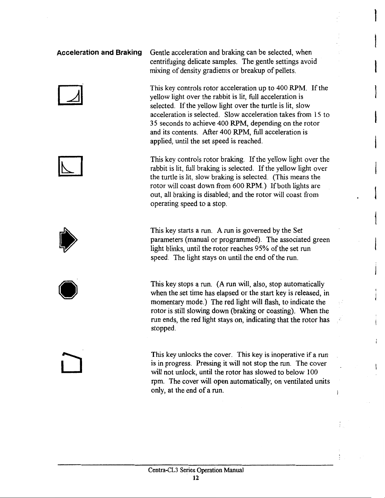
Acceleration and Braking
Gentle acceleration and braking can be selected, when
centrifuging delicate samples. The gentle settings avoid
mixing
This key controls rotor acceleration up to 400 RPM.
yellow light over the rabbit is lit,
selected.
acceleration
3 5 seconds to achieve 400 RPM, depending on the rotor
and its contents. After 400 RPM,
applied, until the set speed is reached.
This key controls rotor braking.
rabbit
the turtle
rotor
out,
operating speed to a stop.
This key starts a run. A run is governed by the Set
parameters (manual
light blinks, until the rotor reaches 95%
speed. The light stays on until the end
of
density gradients
If
the yellow light over the turtle
is
selected. Slow acceleration takes from
is
lit,
full
braking
is
lit,
slow braking is selected. (This means the
will
coast down from 600 RPM.)
all
braking is disabled; and the rotor
or
or
breakup
full
If
is
selected.
programmed). The associated green
of
pellets.
If
acceleration
is
full
acceleration
the yellow light over the
If
the yellow light over
If
both lights are
will
of
the set run
of
the run .
is
lit, slow
15
is
coast from
the
to
l
}
I
l
1
•
This key stops a run. (A run will, also, stop automatically
when the set time has elapsed
momentary mode.) The red light will flash, to indicate the
rotor
is
still slowing down (braking
run ends, the red light stays on, indicating that the rotor has
stopped.
This key unlocks the cover. This key
is
in
progress. Pressing it will not stop the run. The cover
will not unlock, until the rotor has slowed to below 100
rpm. The cover will open automatically, on ventilated units
only, at the end
of
a run.
or
the start key
or
coasting). When the
is
is
released, in
inoperative
if
a run
Centra-CL3
Series
Operation Manual
12
Page 14
3 OPERATION
3.1
Rotor and Accessories
A balanced
unbalanced load produces vibration, and can damage the
unit. A 2 gram load imbalance, at a speed
imparts force equivalent to
Always ensure that the rotor is loaded symrn.etrically, with a
full
complement
tubes. Tube adapters should also be installed symmetrically.
IEC rotors are dynamically balanced at the factory. IEC
matches removable parts (trunnion rings, shields, buckets,
and carriers) to within I gram, and stamps the weight on
each piece. Check these markings, whenever you
interchange parts, to ensure that opposite parts are matched.
Ensure that the total weight
parts, loaded
within 1 gram. The position numbers, present on many
rotors and adapters, identify opposing tube positions.
To
obtain good dynamic balance, opposite loads must not
only be equal
of
gravity. Opposing containers must be alike
thickness, and distribution
especially important for large containers.
lo.ad
is
essential for all centrifuges.
9.
I kg (20 pounds) at rest.
of
accessories, and a
of
samples and removable
in
opposing positions, are equal
in
mass, but must, also, have the same centers
of
glass
full
or
plastic. This
An
of
4600 RPM,
(or paired) set
in
weight, to
in
of
shape,
is
Centra-CL3 Series Operation Manual
13
Page 15

I
Tubes loaded into swinging bucket
symmetric, around the
ax.is
of
rotating the entire rotor 180°,
in
the same apparent positions (not mirror images). In
rotors
must be
rotation. Verify this by
by
hand.
The
loads should be
addition, the loads within each bucket must, also, be
symmetric around the bucket's pivot axis. Verify this
ensuring that each bucket
from the vertical, when the rotor is
balance within each bucket ensures that
tubes swing out to horizontal, when
is
loaded so that it does not tilt
at
rest. Maintaining
the
bucket and the
the
rotor reaches
by
operating speed, applying centrifugal force toward the
of
bottom
causes vibration and premature wear
the tubes. Failure to achieve full swing-out
of
the rotor and the
motor.
Samples oflike (similar) specific gravities may be processed
in
the same run, provided that the samples
of
the same type
are balanced around the rotor, as though they were the only
in
pairs
the rotor.
I
Rotor Balance
Load tubes
1.
Load two tubes at positions:
2. Load four tubes at positions:
3.
Load six tubes at positions:
4.
Loading
recommended.
in
the following manner:
9
and
18.
1,
5 and 10,
7, 3 and 16,
1,
9, 5 and 14, 18,
7, 9, 3 and 12, 18,
an
14
or
12
or
odd number
10
16
of
tubes is not
Caution:
Do
not exceed maximum rated speed for each
rotor/accessory combination. Maximum rated speeds can
in
be found
Section 4.2 - Speed
And
Force
Tables.
I
r -
Centra-CL3 Series Operation Manual
14
Page 16

V~ration
(
All
centrifuges have critical speeds, at which vibration
occurs.
vibration will cease. This inherent condition, also,
during deceleration. An imbalanced load intensifies
As
the
speed increases, beyond
the
critical speed,
occurs
these
critical vibrations. Do not continuously operate this
centrifuge at observed critical speeds.
Rotor Installation
To
install the #243 rotor:
1.
Press the disk (located
on
the
underside
of
the
rotor)
the rotor.
2. Slide the
Release
rotor
the
over
disk.
the shaft, until it snaps into place.
3. Pull the rotor straight up, to insure a positive lock.
3.
PULL
TO
CONf
0
STRAIGHT
IRM
UP
ON
SECURE
ROTOR
ATTACHMENT
0
to
I.
PRESS
AND
Rotor Removal
UP
HOLD
HERE
To remove the 243 rotor:
1.
Press the disk (located on the underside
the rotor.
2.
Lift the
3.
Release the disk.
Centra-CL3 Series Operation Manual
rotor
15
straight up.
2.
SLIDE
AND
RELEASE
ONTO
SHAFI
of
the
rotor)
to
Page 17

Rotor Adapter
To install the shaft adapter for an existing rotor:
1.
Press the adapter disk, and slide the adapter over the
rotor shaft. Release the disk.
2.
Pull the adapter straight up, to insure a positive lock.
3.
Align the rotor keyway with the key on the shaft
adapter, and place the rotor onto the adapter.
4.
Tighten the rotor locking nut (with the provided
wrench), until it tightly engages the rotor.
To remove existing rotors from the shaft adapter:
1.
Remove any sample tubes, shields, buckets, and other
accessories, from the rotor.
2.
Unscrew and remove the locking screw.
3.
Grasp the rotor, and rock
it
front-to-back, and side-to-
side.
4.
Remove the rotor from the shaft.
Centra-CL3
Series
Operation
16
Manual
Page 18

3.2 Starting
and
Stopping a
Run
Read Section 2.5, for a general description
panel. The settings displayed on the front panel always
govern the operation
above the Program icon, shows the unit's operating mode.
It is important that the unit be in the correct mode for the
desired operation.
These digits and symbols are displayed above the program
icon. They can be any
blank The unit
1-99 The unit
program number.
C The unit
program discussed
The display indicates the last parameters selected for each
Program mode operation.
of
the unit. 'f he number
of
the following:
is
in
manual operation.
is
under control
is
set to Rapid Condition, a special
of
in
Section 3.4.
the displayed stored
of
the front
or
symbol,
Centra-CL3
Series
Operation
17
Manual
Page 19

Manual Operation
For
manual operation, set the mode so that the display
above the Program icon
is
blank. Select the desired
temperature (CL3R only), speed/g-force, run time,
acceleration mode, and braking mode. Press START, to
start the spin.
The minutes display counts down, and displays the time
remaining
in
the current spin, during manual operation.
The specified run time begins when the
pressed,
or
when the rotor reaches 95%
START
of
key
is
set speed (see
Timing Mode). Braking begins when the elapsed time
reaches this desired setting. Run time does
not include
braking time.
will
The spin
stop automatically, at the end
interval. A run can, also, be stopped, at any time,
pressing the
STOP
key.
of
the desired
by
The settings can be changed during a manual run. These
changes affect the run
progress.
If
the time setting is
in
changed, during a run, the unit adjusts the count-down
timer, to display the revised setting as the total time
If
run.
the run
the new time selected
will
end.
is
less than the elapsed time,
of
the
The unit's mode (settings) cannot be changed during a
program mode spin.
Centra-CL3
Series
Operation Manual
18
Page 20

- j
. Timing Mode
Four timing modes are available on these units:
timing mode, press the down arrow, under the time display,
until the time goes below zero, and the appropriate symbol
is
displayed.
Momentary
easily separated samples, for simultaneous mixing
samples, and
·of
the tube.
For
momentary spin, set the mode so that three dashes (---)
appear above the Clock icon. Select temperature
only), speed/g-force, acceleration mode, and braking mode,
as for manual operation.
Press and hold the
press the key, and ends when you release the key. In this
mode, you can perform very quick separations
During a momentary spin, the unit displays actual values,
not desired settings. The time display counts upward, and
displays the elapsed time since the
pressed.
Mode
to
(--)
- Momentary spin is useful for
deposit condensate droplets at the bottom
START
key.
The run starts when you
START
To
of
(CL3R
or
protocols.
key was
select a
Hold
Mode
preset time limit), set the mode so that
Time display.
Select temperature (CL3R only), speed/g-force, acceleration
mode, and braking mode, as with manual operation. Press
and release the
the
key,
Hold mode
setting
display counts upward, and displays the elapsed time
spm.
At-Start
down
pressed). The unit
At-Speed
down, when the rotor has reached 95%
display
acceleration to 95%
(HLd) -For
START
and stops only when you press the
is
like manual operation, except that the time
is
not used. During a run
Mode
at
the beginning
will
(ACC) - The set time
is
Mode
(SPd) - The set time
alternately show the set time and SPd, during
hold mode (operation without
HLd
appears in the
key. The run starts when you press
STOP
in
hold mode, the time
will
start counting
of
acceleration (when the start key
originally set to this mode.
will
start counting
of
set speed. The
of
the set speed.
key.
of
the
is
Centra-CL3 Series Operation Manual
19
Page 21

To
select a timing mode, press the Time
and scroll below 0 minutes.
appear. Press and release the Time
choose the desired mode. After three seconds,
pressing the
return
key has not been pressed.
PROGRAM
to
the last selected run time, provided
ACC,
or
START
SPd,
down
keys,
down
HLd,
arrow
the
the
arrow
or
key,
- will
key, to
or
after
display will
up
arrow
The timing mode is stored along with
when a program is saved.
recalled, altered, and not re-saved,
revert back
3.3 Stored Programs
The CL3 Series has an internal memory capable
99 sets
and can be recalled by selecting a program number (from
is turned
for a particular run
change the unit's program, rotor/radius,
during a spin.
Lock
Program
Programs can be locked by scrolling
and pressing the
scroll
program display, after the program number is displayed.
unlock a program, scroll to the desired locked
the
other
If
a saved program has been
the
timing
to
the previous mode,
of
run parameters. Each set,
1-99). Programs are retained in memory, even
off
When necessary, a program can
or
changed permanently.
PROGRAM
to
a locked program, the letter L will flash in the
press the
locked programs cannot be changed.
PROGRAM
key three times. Parameters
when
key three times.
recalled.
or
program, is stored
or
timing modes,
to
the
desired program,
You
parameters,
mode
will
of
holding
if
the
power
be
modified
cannot
When
program
of
you
To
and
Recall
Program
Press a program arrow key,
program number.
The program's set parameters will
START,
Centra-CL3
to
begin this run.
Series
Operation
20
to
Manual
select the appropriate
be
displayed. Press
Page 22

Add/Change Program
Select a program number with the program arrow keys.
current program parameters
will
appear on the display.
Modify the desired parameters, using the parameter
keys, or the ACCEL
or
BRAKE keys. The program .
The
arrow
number will flash, indicating that the program was changed,
and has not, yet, been saved. Make the changes permanent
by pressing the Program Save (file folder) key. The program
number will stop flashing, and the new program settings will
be displayed. The program will remain in memory, until
further changes are made.
To make changes temporary, press
pressing the PROGRAM SA VE (file folder) key. The
program display will flash, to indicate that the values are
now stored
is
not currently operating from program mode. The original
in
program will remain unchanged, as long as the PROGRAM
SA VE (file folder) key is not pressed.
· 3.4 Centra-CL3R Refrigeration
Refrigerated units refrigerate the rotor chamber whenever
the cover
Refrigeration
chamber to the currently displayed temperature setting.
you use the keyboard, and momentarily display a cold
temperature (stepping through stored programs, for
example), refrigeration
If
a temperature, higher than ambient,
will
and
is
closed and the unit
warm the rotor chamber
accessories, while spinning (see Rapid Condition).
START,
without
the manual program, and that the instrument
is
switched on.
is
applied, as necessary,
will
not be activated.
by
to
cool the rotor
is
specified, the unit
wind friction
of
the rotors
If
If
the rotor chamber
will
not abort the spin. However,
differs, at the start
specified temperature. The
the actual and set/programmed temperatures, until the
temperatures come within S
run should not continue
I.
Centra-CL3 Series Operation Manual
21
is
not at the specified temperature, it
if
the rotor chamber
of
a run,
by
more than S°C, from the
°C
display will switch between
0
C.
Press the
at
the actual temperature.
STOP
key,
two
if
the
Page 23

The unit
natural fanning action
angle rotors serves
is
not designed for use as a refrigerator. The
of
the rotating horizontal and fixed
to
maintain a uniform temperature
distribution, inside the chamber. At zero RPM, there is no
correlation between set and actual chamber temperatures.
Rapid Condition
Any frost
should be removed. Allow it
sponge or cloth. When the centrifuge is not
or
condensation, that forms in the rotor chamber,
to
melt, and remove it with a
in
use, turn it
off, or leave the cover open (to disable refrigeration).
is
When the chamber temperature (CL3R only)
above the
set temperature, Rapid Condition will run a rotor at 500
in
rpm, to increase air circulation
the chamber, to quickly
cool the chamber to the set point. When the chamber
is
temperature
will run the rotor at 2800 rpm, to warm the chamber
below the set temperature, Rapid Condition
to
the
set temperature. When the temperature has been reached,
three beeps will sound, and the rotor will brake to rest.
to
Some smaller rotors may not be able
to
higher temperature settings.
warm the chamber
To select this program, press the Program arrow keys, until
a C appears
in
the Program display. Select the desired
temperature, install a rotor, and press the START key.
Centra-CL3 Series Operation Manual
22
Page 24

3.5
Diagnostic Messages and Error Codes
Diagnostics
Message
bAL
Lid
PFAII..
The beeper sounds
in
these situations:
• Two times on power up.
of
• Three times at the end
a spin.
• Five times when a warning occurs
Diagnostic messages appear
in
place
of
the speed display,
the following cases:
Description
bAL
indicates an unbalanced rotor.
to
Open the cover,
Verify that a balanced load is installed. Inspect the rotor, and rearrange the
or
tubes,
Lid
Close the cover,
PFAIL
resume the previous run. Press STOP, to erase this message. PFAII..
indicates a power failure. This message appears when the unit is turned
back on, following the failure. The front panel will alternate between the
PF AIL message and the remaining run time, or elapsed time,
mode.
add additional tubes, with fluid, to balance the rotor.
appears
appears
erase this message.
if
you press the ST ART key, when the cover
to
erase this message.
if
power was interrupted during a run. Press START,
is
not closed.
if
in Hold
to
in
Error
Codes
Error Codes require factory-authorized maintenance. A
typical error means that the internal microprocessor has
detected impennissible readings,
the unit. Error messages appear
an
error code
power.
is
displayed, unplug and reconnect the unit to
If
the error code reappears, tell the service
or
a failure, elsewhere,
in
the speed display. When
personnel which message appeared, when you report the
problem.
Centra-CL3 Series Operation Manual
23
in
Page 25

Error
Message
Err
1
OSPd
rEFR
FSAFE
COPF
COP
UndFI
ILLOP
dffi
Warnings
HEAd,
case, the rotor brakes
Lid,
Description
No
Tachometer
Tachometer signals were not present during the run. The rotor
coasts to a stop. Cover opening
Overs peed
Speed
rotor. The rotor
Refrigeration Failure (Refrigerated only)
The unit displays this code,
45°C, at any time during the run.
Fail-safe Time
Independent circuitry, on the circuit board, has sensed a lack
activity, from the control microprocessor. All power circuits
(including motor, latch, solenoid, etc.) are disabled.
Cop Watchdog/OpCode
The microprocessor
program that controls the centrifuge. The
stop.
COP
The microprocessor COP
a stop.
Undefined
The microprocessor was interrupted
rotor will coast to a stop.
Op-Code
The rotor will coast to a stop
Wrong
The microprocessor discovered wrong direction
during acceleration
during
PF
a spin:
AIL,
•
is
inhibited, after this error.
is
200 RPM above the maximum speed for the installed
will
brake to a stop.
if
the measured temperature exceeds
out
Trap
Error
has
sensed a
Watchdog
Not Enabled
is
Interrupt
Trap
Error
Direction
and
dffi
or
coasts to a stop, and the run ends.
of
Rotation
error messages can occur during a spin.
Jack
of
not enabled.
by
activity, from the
rotor
will coast to a
The rotor will coast
an undefined source.
of
rotation,
of
to
The
In this
Centra-CL3
Series
Operation
24
Manual
i
i
Page 26

4 Applications
4.1
Introduction
This section describes the use
accessories.
rotor or accessory itself This section contains five
reference sections:
• Speed and Force Tables
• Derating Table for Dense Samples
• Chemical Resistance Table
• Decontamination Table
• Nomograph
Caution: Do
rotor/accessory combination. Maximum rated speeds can
be found
Relative Centrifugal
speed varies with the rotor, and with the distance away
(rotating radius) from the shaft
rotation). The rotating radius
inside tip
Speed and Force Tables indicate the maximum speed and
RCF that the Centra-CL3/CL3R can achieve, with various
rotor/accessory combinations. The Derating Table specifies
reductions
specific gravity above 1.2.
More
detailed information
not
exceed maximum rated speed for each
in
Section 4.2 - Speed
Force
of
the tube, away from the centrifuge shaft. The
in
maximum RPM, when spinning samples with
of
specific rotors and
is
shipped with the
And
Force
(RCF or G-force) at a given
of
the centrifuge (center
is
measures to the furthest
Tables.
of
Centra-CL3 Series Operation Manual
25
Page 27

Corrosive Solvents
Use
of
any tube above its rated RCF can cause tube
cracking.
To
avoid this, compare the G forces, specified
in
the Speed and Force Tables, with the ratings for the tubes
If
that you are using.
the tubes are not rated for the force
that the centrifuge will apply, look up their reduced G force,
and enter it on the control panel.
is
made
of
Your IEC centrifuge
materials designed to resist
immediate attack from most laboratory chemicals.
Prolonged exposure should be avoided, by immediately
removing the chemical from rotor
accessories placed in the chamber are made
or
assembly. Rotors and
of
a variety
of
materials, including aluminum and polypropylene. The
Chemical Resistance Table shows the suitability
of
material with different classes
reagents.
of
each
Section 5
.2
describes how to clean and remove corrosion
from the chamber, rotors, and accessories. Follow these
instructions, and clean spills promptly, to minimize the
effect
of
corrosive chemicals and to avoid expensive repairs.
Centra-CL3 Series Operation Manual
26
Page 28

4.2 Speed and Force Tables
4 Place
Carrier
6560E
6561E
6562E
6563E Short
R t P k o
Rotor
(Use reauires 50968 taoered
No.
Places
4 50 325/320**
or
Rotor
Number
ac ages
243
for
Use
of
Places
2
5 Falcon/Corning
9
9
Volume
Falcon/Corning
(100-125mm) 4000 3200 18
Blood Tubes
(75-lOOmm) 4000 3200
Blood Tubes
52151
215 4 Place Horizontal Swinging Bucket
shaft
of
Tube
Volume
(ml)
Trunnion/
Shield
or
Carrier (rpm) (xg) (cm)
only
50 ml
15
ml
Long
52152
with
Centra-CL3 and Centra-CL3R
Maximum RPM
4000 3200 18
4000 3200
52153
' ' '
adapter)
Max Max Max
Speed
4100
RCF
2650
Maximum
52154
Radius O.D. x
Common
14.0 30 x 116
RCF
xg
Length
Tube
Radius
(cm)
18
18
(mm)
Size
'
\
4
4
8
12
12
16
20
4
**Order
50 350/323**
10
50
10
10
5-7
3 - 5
adapter 1106 and
310/356 4300
326/320 3600
355/356
366/1013 4100
36611018
366/369
3
1024
3800 2050 15.2 Falcon/Corning Conical
2750 13.2 17.2 x 113
2050 14.2 30 x 116
3600
4150
4600
2050
571
cushion, to spin
Centra-CL3 Series Operation Manual
1900
2400 12.8 16.5 x 10⁷
2450 12.8 14.2 x
2625
500
15
ml Falcon/Corning Conical Tubes
27
13.2 17.2 x 112
11.1
10.6
16
x 75;
16
103
13
x 75;
13
12.6 x 83 10-12 x 75
I" x 3" Microscope Slide
x 100
x 100
Page 29

Rt
ac age
P k o or
52212
Rotor
(Use
No.
Places (ml)
221
reauires
of
6
6
6 Place Horizontal Swinging Bucket
50968
Tube
Volume
10
15
tapered
Shield
shaft
adapter)
Max Max
Speed
(rpm) (xg) (cm)
356
303 4000 2600 14.6 17.2 x 119
4400 2800 13.0 17.2 x 10²
RCF
Max
Radius
0.0. x Length
Falcon Corning Conical
Kimble 45168-125
Rotor 244 2-Place (Tray) Horizontal Microplate
(Use
reauires
of
No.
Places (ml)
4
2
50968
tapered
Tube
Volume Carrier
-
-
included#
49852 4000*
shaft
adapter)
Max
Speed
(rpm)
4000*
Max
RCF
(xg)
1800
1800
Max
Radius
(cm)
10.0
10.0
Width x Length
86 x 128
86 x 128 x 55mm
(mm)
(mm)
(96
well) Microplates
Deep Plates
*Replacement carrier is IEC No. 49852
**
See derating table for 244 rotor
Rt
o or ac age
P k
Rotor
(Use
No.
Places
*With IEC 315 Conical Cushion
reauires
of
6
6
801
Tube Max Max
Volume
(ml)
58012
6-Place Fixed Angle 45°
50968
tapered
Shield
50 305
50
320 5200
shaft
adapter)
Speed RCF
(rpm)
4600
(xg)
2950
3300
Max
Radius
(cm)
12.1
10.8
0.0. x Length
30 x 133
Falcon
Coming
30
x 116
Corning 8300-50
Conical•
(mm)
Centra-CL3 Series Operation Manual
28
Page 30

Rotor
(Use
reauires
804S 4-Place Fixed Angle 45°
50968
taoered
shaft
adapter)
with
323 Sealed Dome
Shields
No.
of
Places
4
4
*
Order
R t P k o
or
Rotor
(Use
reauires
No.
of
Places
12
12
Tube
Volume
(ml)
50
60
adapter 1106
ac age
Shield
323*
341
and
571 cushion, to spin
58092
Max Max Max
Speed
(rpm) (xg)
.
809
12-Place Fixed Angle 45°
50968
taoered
Tube Max
Volume
(ml) (rpm)
10
15
shaft
adapter)
Shield Speed
356
303 4800
RCF
7200 6675
2500 1000
15
ml
Falcon/Coming
Max
RCF
(xg) (cm)
5300
3200
2880
Radius
(cm)
11.5
14.3
Max
Radius
10.2
11.2
O.D. x
Falcon/Corning Conical
Coming
tubes
O.D. x
17.2 x 88
17.2xl02
Length
Length
(mm)
(mm)
12 15
R t P k o
or
Rotor
(Use
requires
No.
of
Places
24
24
24
4200
ac age
302
58153
815 24 Place Fixed
50968
Tube
Volume
(ml)
IO
15
15
taoered
Shield
shaft
adapter)
Max
Speed
(rpm) (xg)
356 4800
303
302 3800
4200
Angle
Max
RCF
2860/2340
2360/1970
2100/1800
2480
33°
12.6
Max
Radius
(cm)
11.l/9.l
12/10
13/11
17.2 x 122
Falcon/Corning Conical
0.0.
x Length (mm)
17.2 x 88
17.2xl02
17.2 x 122
Falcon Coming Conical
Centra-CL3 Series Operation Manual
29
Page 31

Rotor
p k
ac age 58162
Rotor
(Use reauires
No.
Places
*With
Rotor
(Use reauires
No.
Places
816 8-Place Fixed Angle 33°
Tube
of
Volume
(ml)
8 50
8 50
IEC 315 cushion, order adapter 1106 and cushion 571
818
Tube
of
Volume
(ml)
12
50968
tapered shaft adapter)
Shield
320 4600 2800 11.7 30 x 115
305 4300 2650 12.8
Max
Speed RCF
(rpm) (xg) (cm)
Max
12-Place Fixed Angle 35°
50968
tapered shaft adapteri
5
Adapter
Number
-
Max
Speed RCF
(rpm)
8500
Max Max
(xg) (cm)
6060 7.5
Max
Radius
Radius
0.0.
x
Length
Corning
30 x 134
Falcon/Corning Conical*
to
spin Falcon/Corning tubes
8300-50
0.0.
12
x 80
x
Length
IEC
(mm)
2804, 2840
(mm)
12
12
12
Rotor
(Use reauires
No.
Of
Places
10
1.5 - 2
B-D/.5
.4/.25 5760
819 10-Place Fixed Angle 35°
Tube
Volume
(ml)
50968
10
5762
5761
tapered shaft adapter)
Adapter
Number
-
8500 4680
8500
8500
Max Max
Speed
(rpm)
8500
4770/3960
4680/3630
Max
RCF
(xg) (cm)
6060 7.6
Radius.
5.5
5.915.0
5.915.0
I
0.0.
16. l x 85
11x66
8
x66
6
x66
x
Length
(mm)
IEC 2046, 2067, 2801, 2850
Centra-CL3 Series Operation Manual
30
Page 32

Rotor 836 6-Place Fixed Angle 30°
(Use
reci
uires
50968
taoered shaft adapter)
Max
(xg)
6060
No.
of
Places
6
Tube
Volume
(ml)
30
Adapter
Number
-
Max
Speed RCF
(rpm)
8500
Max
Radius
(cm)
7.5
O.D. x
25.8 x
Length
100
IEC
(mm)
2047,
2055,
2802
6
6
6 3
Rotor
(Use reQuires
No.
Places
12
of
841
Tube
Volume
(ml)
1.5
12
12
12
15
5
5965
5966
5967
8500
8500
8500
5820
5650
5490
12-Place Fixed Angle 45°
50968
tapered shaft adapter)
- 2
B-D
.5
.4
Adapter
Number
-
5763
5763
5764
Max Max Max
Speed
(rpm)
8500
8500
8500
8500
7.2
7.0
6.8
RCF Radius
(xg) (cm)
4680
4770
3960
4680
16.1x10⁹
12.1x112
10.9 x 95
5.8
5.9
4.9
5.8
O.D. x
Length
(mm)
11x39
B-D Microtainer Tubes
8 x
66
6 x
46
12
.25
5764
Centra-CL3 Series Operation Manual
8500
3630
31
4.5
6 x
46
Page 33

Microtube Rotors
(Use requires 50036
Rotor Cat. No.
No.
hub
of
1.5 ml
adapter
Tubes and Tube Size
on
50968 tapered shaft
adapter)
Adapter
Cat. No Speed
Max
(RPM)
-
Max
RCF
(xg)
6740
Radius
(cm)
8.35
8911
(Aerosol 24 x 0.5 ml PCR microtubes
Contained)
8512
8522
8532
24 x 0.6 ml
24 x 0 .4 ml microtubes 5764** 6740
24 x 0.25 ml microtubes 5764** 5860
24 x 1.5 ml
24 x 0.6 ml
24 x 0.5
24 x 0.4
24 x 0.25 ml microtubes 5764**
48 x 0.5 ml PCR microtubes
24 x
40
x 0.4
40 x 0.25
BID Microtainers™ 5763** 6830
BID Microtainers™ 5763** 6830
ml
PCR microtubes 5763**
ml
microtubes 5764**
BID Microtainers ™
ml
microtubes
ml
microtubes
5763** 8500 6020
-
8500 6020
-
8500
-
-
-
8500
6740
6740
5860
6460
6060
6950
6790
6060
8.45
7.45
8.35
7.25
8.35
8.45
7.45
8.35
7.25
8.00t
7.50t
8.60t
8.40
7.50
40 x 0.8 ml (6x50 mm) glass
Microtainers® is a registered trademark
** Order 2 pks
t Outer row holds 24 tubes
:j:
Inner
1
IEC 891 Rotor Provides Aerosol Containment and has been tested for microbiological
containment by PHLS-CAMR, Porton Down. Meets requirements
Pathogen Final Rule: (Regulation 29 CFR Part 1910.1030. Complete
Containment Cover, IEC 50525 Inner and IEC 36597 Outer rubber
2
IEC 851, 852, 853 rotors
of
adapters separately. IEC 5763 and 5764 are packaged 12/pk.
row holds 24 tubes
Centra-CL3 Series Operation Manual
of
Becton Dickinson
-
of
US
OSHA
with
0-ring
6870
32
8.50
Bloodborne
IEC 50417 Aerosol
seals.
Page 34

245 Horizontal Rotor 4x250 ml
(Use reauires 50968 taoered shaft adapter)
of
Tubes x Tube Size
No.
40 x
1.5
ml
microtubes
40 x 3
ml
48
x 5
ml
5-7
ml
(13
x
75-lOOmm
28 x 10-15
16 x 15
12
4
4 x
4 x 175 ml (Falcon 2076) 61.0
ml
x 30
ml
x 50
ml
50
ml Falcon/Coming Conical
vacutainers)
ml
vacutainers 16.2
Falcon Conical
Max Tube Size
O.D.
mm
-
10.9
12.1
13.3
-
25.5
28.6
-
Ultrac
L.
mm
-
75
131
131
llO 7225
-
131
131
Adapter
7228
7228
7226
7238
7230
7223
7231
- 7231
131
*
Max
RPM RCF
2750
2750
2750 1450
2750 1450 17.2
2750 1450
2750 1475
2750 1450
2750 1450
2750 1450 17.2
2750 1475 17.6
Max Radius
(cm)
xg
1375
1450
16.2
17.2
17.2
17.2
17.6
17.2
17.2
t
l
I
I
4
x 200 ml (Nunc 376813) 61.0
4 x 225
4 x 250 ml (IEC 2502, 2504)
ml
(Falcon 2075) 61.0
* Also order Falcon 2090 cushions
**Also order IEC
5792 cushions
61.0
131
131
131
**
2750 1475 17.6
*
-
2750
2750 1500 17.8
1475 17.6
I
Centra-CL3 Series Operation Manual
33
Page 35

268 Horizontal Rotor 4x250
(Use reauires 50968 taoered shaft adapter)
ml
No.
of
Tubes x Tube Size Max Tube Size
mm
O.D.
40 x 1.5 ml microtubes
40 x 3 ml
48 x 5 ml
40
x 7 ml
28 x 7-10 ml 16.2
12 x 15 ml Falcon Conical
12 x 30 ml
4 x 50 ml
4 x 50 ml Falcon Conical
4 x 75 ml (IEC 2059)
4 x 175 ml (Falcon 2074)
- -
10.9
12.1
13.3 106
-
25.5
28.6
- -
38.1
61.0
L.mm
75
106
106
-
106
110
112
125
Ultrac
Adapter
7228
7228
7226
7236
7225
7234
7223
7222
7231
7221
*
Max Max Radius
RPM RCF
xg
3425 1800 13.7
3425
3425
3425 1925
3425 1925 14.7
3425 1976
3425 1925 14.7
3425
3425 1925
3425 1925 14.7
3425 1975
1925
1925 14.7
1925 14.7
(cm
14.7
14.7
15.1
14.7
15. l
4 x 250 ml (IEC 2261, 2051)
* Also order Falcon 2090 cushions
61.0
Centra-CL3 Series Operation Manual
125
34
-
3425
2000
15.3
Page 36

958 Horizontal
(Use
reauires
50968
taDered
Rotor
shaft
6x50 ml
adapter)
No.
of
Tubes x
48 x 5 ml
36 x Shell vial
36 x 7
ml
ml
30 x 5
ml
24 x 7
18
x 10 ml
10
24 x
18 x 10
6 x
6 x
12 x 50
ml 17.2
ml 17.2
15
ml
15
ml 17.2
ml 30.0
Tube
Size
Max Tube Size TR.
O.D.
mm
13.6
17.7
17.7
12.6
14.2
16.5 110 366 1013
17.2
L.mm
92
77
88
98 366
106
103
112 355 356 2450
119 310 356 2950
134
120 326 320 2400
Ring
-
-
-
366 1018 2800
354 356 2400
310
Carrier
or
Shield
381 2600
379 2900
380 2600
369
303
Max
RPM
3200
2800
2700
Max
RCF
xg
1125
1300
1125
1600
1375
1400
1025
1075
1575
1475
llOO
Radius
(cm)
15.0
13.7
15.0
14.0
15.7
15.9
16.1
16.1
16.1
17.6
16.9
6 x 50
ml
6 x Microscope Slides
Hemato-Kit
(Use
reouires
The 930 Hemato-Kit can convert the
providing a simple, economical way
packed in about ten minutes, at 7800 RPM/6200 xg. Kit includes numbered 24-place rotor
for 1.75 x
for installing rotor.
Order Cat.
75
No.
Rotor
1116
hublock
mm capillary tubes, 1505 gasket for tubes, cover, hublock adapter and wrench
An
930 Hemato-Kit and Cat.
930
adapter
accessory microcapillary tube reader available, to complete the system.
30.0
l"
on
50968
CL3
Series into a micro-hematocrit centrifuge,
to
perform occasional hematocrits. Blood cells are
No.
Centra-CL3 Series Operation Manual
124 325
3"
tapered
2201 Microcapillary Tube Reader.
shaft
35
-
adapter)
320
1025
2800
1800
1475
500
16.8
13.5
Page 37

4.3
Derating Tables
Dense
Samples
The Speed and Force Tables list the maximum speed for
each rotor/adapter combination for the CL3 Series. These
speeds are guaranteed, for samples whose specific gravity
not greater than:
• 1.2 for swinging bucket rotors
1.5
•
For denser samples, the maximum guaranteed speed
reduced ( derated) by a factor from the table below:
for fixed angle rotors
Specific
Gravity
1.2
1.3
1.4
1.5
1.6
1.7
1.8
1.9
2.0
2.1
2.2
2.3 .721
2.4
2.5
2.6
2.7
2.8
2.9
3.0 .632
Derating
Swingin2
1.000
Factor
Bucket
.960
.925
.894
.866
.839
.816
.794
.774
.755
.738
.707
.692
.678
.666
.654
.642
for:
Fixed
1.000
1.000
1.000
1.000
.967
.939
.912
.888
.866
.844
.825
.807
.790
.774
.758
.744
.731
.719
.707
is
An~le
is
Centra-CL3
Series Operation Manual
36
Page 38

Derating Example:
used with samples with a specific gravity
faster than
9,670 RPM. (10,000 x .967 = 9.670)
An
angle rotor, rated for 10,000 RPM,
of
1.6, cannot spin
Specific gravities greater than 3.0.
the formula:
You can use the same formula to compute derating factors
for specific gravities greater than
• S0 is the maximum specific gravity allowed before
derating (1.2
•
Sa
is the actual specific gravity
Caution:
Higher speeds
wear on the centrifuge, and can cause
and
under
Do
damage caused in this
warranty.
or
1.5, depending
not exceed the rated speed
or
specific gravities will impose unnecessary
manner
This table is based on
3.0.
on
the type
of
the sample.
rotor
are
of
or
specific gravity.
failure.
not covered
rotor.
Wear
Centra-CL3 Series Operation Manual
37
Page 39

244 Rotor
The 244 rotor
microplates. The weight
equally distributed between the
is
designed for centrifugation
of
the loaded microplates must be
rotor's
of
multi-well
two carriers. The
maximum rated speed for the 244 rotor, when each
carriers
is
4000
is
loaded with 280 grams (total load
rpm.
of
560 grams),
of
the
Caution: Loads greater than 280 grams (weight
of
the
microplate and sample) must have maximum speed derated
(according to the following table), to avoid
rotor failure.
Derating Table for 244 Rotor
Load per Carrier
( l!rams)
280
300
320
340
360
380
400
450
500
600
Greater than 600
Max. Speed
(rpm)
4000
3600
3300
3000
2800
2600
2400
1900
1400
800
do not use
Centra-CL3
Series
Operation Manual
38
Page 40

4.4 Chemical Resistance
The
CL3
from most laboratory chemicals. A variety
aluminum and polypropylene, comprise the rotors
The Chemical Resistance table shows the suitability
with different classes
Table
Series is made
of
materials that are designed to resist attack
of
materials, including
and
accessories.
of
each material,
of
reagents.
.
Acids, dilute
Acids*, strong or cone.
Alcohols, aliphatic
Aldehydes G
Bases
Esters
Hydrocarbons, aliphatic
Hydrocarbons, aromatic F
Hydrocarbons, halogenated
Ketones
Oxidizing Agents, strong
Salts
*For
or
weak
...
Ox1d1z1ng
PA - POL YALLOMER
PCPE - POLYETHYLENE
PP - POLYPROPYLENE
PU
- POLYURETHANE
NL - MODIFIED PHENYLENE OXIDE (NORYL)
DN - ACETAL HOMOPOL YMER (DELRIN)
CN - ACETAL COPOLYMER (CELCON)
NN - NYLON
PS - POLYSTYRENE
Acids, see
POLYCARBONATE
PA
E
E
E
E
G
G
F
G
F
E
"Ox1d1zmg
Note: Chapter
5 describes how to clean
and
remove corrosion from
chamber, rotors, and accessories. Follow the instructions,
spills promptly,
minimize the effect
of
corrosive chemicals
to
avoid expensive repairs.
Plastic
PC
E E E G E F N F E G G F F N F
N E
G E E F E E
F G G G G G G F N
N
N
F G G E
N G F N N
N F
N
N
E
. .
pp
PE
E
G G N
PU
NL
F N
E
E N G N
E
N
F
N N G E G N
G G N N
F F
E
E
Agents, strong" .
N N
N
E E E E E E
DN
CN
NN
PS
Tl
N N N F
E N E E E E E F E
F
G
G
G E N
E
E E
E E E N E
N N N N N N
E E E E E
E E E E
E E E E E N N N
N
E E
E E E
E
E
N N N
E
N
E G G G E N N
E
E
Tl - TITANIUM
SS
- STAINLESS STELL
AL - ALUMINUM
MB-
MANGANESE BRONZE
MG - MAGNESIUM
RR-RUBBER
BN
- BUNA-N
VN
-VITON
PF
- PHENOLIC FIBER
Metal
SS
AL
MB
E E
E E
E E
E E N N E
E
F
N N N N F E
F F
F
and
MG
E N
N
N
the
clean
and
Other
RR
BN
E E
F
E
N E
E
G
G N
E E
N N
E E E
VN
G
G
F
N
PF
E
N
E
E
N
E
E
E
E
E
E
E
Classification of Resistance
E=
Excellent
G= Good
F=
Fair
N= Not Recommended
Centra-CL3 Series Operation Manual
39
Page 41

4.5 Decontamination Table
Compatible Processes
Sterilization
Mechanical
Autoclave•
Ethlene Oxide Gas
Dry Head 160°C@2Hrs. u u u u u
Chemical
Ethanol
40% Formalin s s s
Methanol
2-Propanol s s s
5% Sodium Hypochlorite
3%
Hydrogen Peroxide s s s s s s M
100% Hydrogen Peroxide
5% Phenol Solution M u u
*For
PAPC-POLYCARBONATE
PE - POLYETHYLENE
PP - POLYPROPYLENE
PU
NL - MODIFIED PHENYLENE OXIDE (NORYL)
ON
CN
NNPS - POLYSTYRENE
Methods
...
Ox1d1zmg
POLYALLOMER
- POLYURETHANE
- ACETAL HOMOPOL YMER (OELRIN)
- ACETAL COPOLYMER (CELCON)
NYLON
Acids,
For
Decontamination
Plastic
pp
PA
PC
PE
PU
s M u s M u
s s s
s s s
s s s s u s s s u M
s
u s
s M s s M s s s u M s s s s
M s s s u s s
s
....
s s s
s s s
s
s s
s u u M M u M
see
. .
"Oxidizing Agents, strong".
ON
NL
s
s s s s
u u
s
u s u
u
u u u
Tl - TITANIUM
SS
AL - ALUMINUM
MB
MG - MAGNESIUM
RRBN-
VN-VITON
PF
PT - PAINTED SURFACES
Metal
Tl
CN
NN
PS
s s
u
u u u
s
s
u
u
u
s
s u s
s
- STAINLESS STELL
- MANGANESE BRONZE
RUBBER
BUNA-N
- PHENOLIC FIBER
SS
AL
s s s
s
s s s s
s
s
u s
s s
s
s
s s
s
s
s
s s M
M u
s s s
s s
M M
s s
M M
Other
MB
MG
RR
BN
VN
s s s s
u
s
u u u u
s s
s
s s
s s
s
M
u
s s
s
s s
u s
s
u s
s
s s
u u s u s
s u s s s
u u s
s
M M
*Autoclaving
12·c
2 ATM (15 PSIG)
....
S=SATIFACTORY
M=MARGINAL
U=UNSATISFACTORY
u s s u
20
mnin.@
Household Bleach
PF
s M
s
s
s
s u
PT
s
u
s
s
s
s
M
M
Warning:
This chart describes the material compatibility
specify the adequacy
for material compatibility during centrifugation.
of
sterilization. Refer
Centra-CL3 Series Operation Manual
to
40
of
various sterilization methods.
It
does not
section 4.4 - Chemical Resistance Table,
Page 42

4.6
RCF
Nomograph
20
18
16
14
12
10
0
Q)
9
.c
~
8
fl)
::I
=o
7
(IS
a:
Cl
c
6
+:;
!!!
0
a:
5
4
3
50
45
40
35
30
25
~
!?
Q)
20
E
E
18
~
Using
VI
16
..2
"'O
Ill
a:
14
Cl
.5
ta
12
0
a:
•••
•••
•• • centrifugal force is 1,000 xg (gravity).
·<10
9
8
7
6
the RCF Homograph
To
detennine
force (ref), place a straightedge on the
nomograph connecting the known speed
(rpm)
point
Iha ref axis is the force.
For
and the speed
II the force and Iha radius are known. Iha
corresponding speed
the
relallve centrifugal
and
the known rotating radius. The
at
which the stral!fitedge intersects
example. if lhe rotating radius is 1 O
is
3,000 rpm, the relative
To Calculate RCF
RCF
.,
.00001118 x r x N'
RCF • relative centrifugal force (gravhies)
r • rotating racius (centimeters)
z
rotaUng
N
speed
can
be determined.
(rev.
per
cm
min. or rpm)
20,000
15,000
30,000
20,000
10,000
5,000
Ci)
j!
~
~
2,000
El
Q)
......
············
~--·~:~···
····~
~
;;:
'E
Q)
(.)
Q)
.::!:
1i5
Qi
a:
500
200
.~1
100
50
20
10
10,000
6,000
4,000
......
3,000
2,000
1,000
500
-···
';1~
.s
~
c:
E
....
Q)
Q.
(/J
c:
.2
"5
0
>
Q)
a:
I
'"O
Q)
Q)
Q.
en
r~•
1-·
':,t
..
'-~
5
0
200
Centra-CL3 Series Operation Manual
41
Page 43

5 Maintenance
5.1
5.2
Introduction
Care
and
Cleaning
This chapter explains how to keep your unit in good
operating order.
decontaminating, and storing. This chapter, also, covers the
cover interlock bypass.
See the end
warrantees.
Keep your centrifuge clean, to ensure good operation, and
to extend its life.
Clean the sample chamber, rotor, and lid, at the end
work day, and immediately after any spill.
chamber, use a damp sponge, warm water, and a mild liquid
detergent, suitable for washing dishes by hand, such as
Ivory® liquid. Do not use caustic detergents,
that contain chlorine ions. These attack metals.
It
includes instructions for cleaning,
of
the chapter, for information on service and
To
clean the
or
detergents
of
each
Remove stubborn stains with a plastic scrub pad. Do not
use steel wool, wire brushes, abrasives,
create corrosion sites. Never pour water directly into the
rotor chamber.
Centra-CL3 Series Operation Manual
43
or
sandpaper. They
Page 44

Scrub the rotor's tube cavities with a stiff test tube brush
that has end bristles and a non-metallic tip.
Dry each part,
after cleaning, with a clean, absorbent towel.
If
glass breakage occurs, remove
If
immediately.
cushions. Particles
breakage recurs, replace
of
broken glass embed in the plastic
all
broken pieces
all
adapters and
or
rubber accessories. Glass particles can come in contact with
new glass tubes, creating pressure points that may result
breakage recurring. Glass particles,
in
the chamber, grind
in
to
a fine gray dust, during centrifugation. This dust can coat
of
the inside
the centrifuge.
Corrosion
IEC manufactures and finishes rotors and
structural accessories
corrosion. To maximize the
inspect the rotor cavities for corrosion, especially
to
give maximum resistance to
life
of
the unit, continually
if
you use
chloride ion solutions, such as sodium chloride (saline), and
sodium hypochlorite (household bleach), because these
solutions attack most metals. Clean the rotor, rotor
chamber, and accessories (particularly the sample
compartments and bucket cups) thoroughly, after each
exposure. Inspect
all
surfaces, under bright light, for
corrosion. Be aware that small crevices grow deeper,
eventually resulting in system failure.
Replace the shaft, locking nut, rotor, or accessories,
if
they
become corroded, cracked, deformed, or gouged.
Centra-CL3
Series
Operation
44
Manual
I'
t·
'I
Page 45

If
you see any corrosion, remove it immediately, using the
following procedure:
1.
Follow the cleaning procedure, at the start
of
this
section.
2.
Soak the product
in
mild hand dish washing detergent,
and scrub the product thoroughly with a stiff test tube
brush. The brush should have end bristles and a nonmetallic tip.
3.
Soak the product, again, in clear warm water, for a
minimum
of
an
hour.
4. Rinse the product in warm water, then in distilled water.
5.
Dry the product, thoroughly, with a clean, absorbent
cloth.
Storage
Decontamination
Caution:
discontinue use
If
this procedure does not remove the corrosion,
of
the product.
Store parts on a soft surface, to avoid damage.
Rotors and other parts should be clean and dry. Store them
open to the
air,
not
in
a plastic bag, so that any residual
moisture evaporates. Face the parts upward, to avoid
moisture retention
If
tube breakage occurs, releasing toxic, infectious,
in
the cavities.
pathogenic, or radioactive material into the unit,
decontaminate the chamber.
Rotors have sealed containers, that provide aerosol
containment and, if used as directed, keep spillage confined.
If
breakage occurs, it may be sufficient
to
only
decontaminate the sealed carriers.
The Decontamination Table,
of
sensitivity
various materials to common sterilization
procedures. When using a 1-to-10 dilution
in
Chapter
4,
lists the
of
household
bleach (sodium hypochlorite), to decontaminate metal rotors
or accessories, follow decontamination by the corrosion
cleaning procedure (See 5.2), since chloride ions attack
most metals.
Centra-CL3 Series Operation Manual
45
Page 46

Always decontaminate for the minimum recommended time.
If
you observe corrosion, remove it, as described earlier;
of
discontinue use
the method; and use an alternate
decontamination procedure.
Polypropylene sealed carriers can be autoclaved. Remove
any sample tubes, before autoclaving, unless they are
full
of
completely
other tube closures, before autoclaving,
sample. Remove caps, stoppers, and
to
keep the tubes
from collapsing under pressure. Autoclave the rotor and
accessories at
° C @
15
psig for 20 minutes. Do not
121
stack polypropylene rotors during this process. After
cooling, perform a normal cleaning operation, as described
above.
1
Repeated autoclaving seriously degrades the performance
polycarbonate sealing covers.
5.3 Cover Interlock Bypass
The cover
remove samples from the unit, before power
the cover interlock bypass, after the rotor has come to a
stop.
To bypass the cover interlock:
1.
Unplug the centrifuge.
2.
Locate the hidden plastic plug, underneath the ledge
below the IEC CL3 logo.
3.
Use a screwdriver to remove the plug.
4.
Pull the attached cord, to release the cover interlock.
5.
Replace the plug
Do
not perform this operation routinely. The centrifuge's
cover interlock provides operator safety.
cover
to
stopped.
will
remain locked,
in
the hole.
if
power fails.
If
you need
is
restored, use
It
allows the
be opened promptly, whenever rotation has
of
to
Centra-CL3
Series
Operation Manual
46
Page 47

. 5.4 Condition of Returned Equipment
5.5 Warranty
Contact IEC, or your dealer, and obtain a return
authorization (RGA), before returning equipment
The RGA paperwork includes a Certificate
Decontamination for you to sign.
It
indicates that you have
of
goods
to
IEC.
performed the proper steps for decontaminating your unit.
All
Warning:
of
radioactivity,· and free
pathogenic,
IEC refuses
certificate
returned units must be decontaminated,
or
toxic materials.
all
return equipment shipments, until the signed
is
received.
of
hazardous, ·infectious,
free
You must prepay transportation to the service depot.
of
IEC wants you to be satisfied with the quality
your CL3
Series centrifuge. We warranty your IEC centrifuge for one
year, and IEC rotors for seven years. We
replace
from the date
any
of
these products that
of
its delivery, due to defects
fail,
will
repair
or
within this period,
in
material and
workmanship, and we will ship you the repaired product or
its replacement at our expense. You must use IECapproved rotors and accessories, and genuine IEC spare
parts. This warranty does not apply to any instrument that
has
been repaired without authorization or abused.
THE FOREGOING OBLIGATIONS ARE IN LIEU
OTHER OBLIGATIONS
NEGLIGENCE, AND
MERCHANTABILITY OR OTHERWISE, EXPRESSED
IMPLIED
OUR ENTIRE AND EXCLUSIVE LIABILITY, AND
EXCLUSIVE REMEDY,
CONNECTION WITH THE SALE OR FURNISHING
GOODS
USE, INSTALLATION,
EVENT BE
CONSEQUENTIAL DAMAGES WHATSOEVER AND
LIABILITY UNDER NO CIRCUMSTANCES
THE PURCHASE PRICE FOR THE GOODS FOR WHICH
LIABILITY
Centra-CL3 Series Operation Manual
IN
FACT OR
OR
PARTS, THEIR DESIGN,
LIABLE
IS
CLAIMED.
47
AND
LIABILITIES INCLUDING
ALL
WARRANTIES, OF
BYLAW.
FOR
ANY CLAIM OR
OR
OPERATION. IEC
FOR
ANY
SPECIAL OR
THE FOREGOING
SUITABILITY
OF
BUYER'S
DAMAGES
WILL
WILL
EXCEED
ALL
OR
STATES
OF
FOR
IN
OUR
IN
NO
Page 48

6 Specifications
I
I
Maximum Speed:
Maximum
Maximum
Maximum Sample Volume:
Operator Controls:
Chamber Temperature*:
Speed:
Spin Duration:
Force:
Number
of
Tubes:
8,500
RPM
(841 fixed angle rotor)
4,000
RPM
(243 swinging bucket rotor)
6,200 xg (930 fixed angle rotor)
3,200 xg (243 swinging bucket rotor)
48 x
5 ml sealed (243 rotor)
12
x 25 ml Universal sealed (243 rotor)
20 x
15
ml Falcon/Corning sealed (243 rotor)
8
x 50
ml
Falcon/Corning sealed (243 rotor)
4
x 250 ml (243 rotor)
4
x Microplates/2 x Deep plates (244 rotor)
1 liter (243 rotor)
by 1 C
0
15
seconds
-9° C to 40°
0 - 8,500 RPM, by 100 RPM
0:01 through 0:59, by 1 second
1 :00 through 4:45, by
5 through 99 min., by 1 min.
Momentary operation mode
Hold mode (indefinite duration)
At-Start timing mode
At-Speed timing mode
C,
Repeatability:
Temperature*:
Rotation:
Motor:
Refrigerant*:
0
± 1 C
in the range from +4° C to +22° C
10
RPM
to
Brushless
HP-80, CFC-free
Centra-CL3 Series Operation Manual
49
DC
Page 49

Power Requirements
Voltage:
\ -
.)..
3750 - 120V/60
Hz
3751 - 220-240V/50/60 Hz
3755 - 120V/60
3756 - 220-240V/50
3757 - 220-240V/60
Hz
Hz
Hz
Full specification compliance is guaranteed for up to
±5% line voltage specified.
Function guaranteed up to ±10%
ofline
voltage
Operating Current:
Heat Output:
(max)
CL3:
CL3R:
Dimensions (CL3R)
Sample Loading Height:
Cover Closed Height:
Cover Open Height:
Width:
Depth:
Weight:
(shipping weight)
(net weight)
~~-..#..-.
Dimensions (CL3)
Sample Loading Height:
Cover Closed Height:
Cover Open Height:
Width:
Depth:
Weight:
(shipping weight)
(net weight)
•,,•·,.
3750 - 5.5 AMPS
3751 - 3 AMPS
3755 -
10 AMPS
3756 - 5 AMPS
3757 - 5 AMPS
1500 BTU/Hr
2700 BTU/Hr
32 cm
11::
" in) .
':
cm
i , -
.~·
in)
~cm·.·~:
'o
en~
~~
c1r.
68 kg
C •
(:'
(l);:
.:1)
:=.
in)
~
-~i)
;;JS)
46 kg (lOOibs)
32 cm (12.5 in)
37
cm
(14.5 in)
84 cm (33 in)
49
cm (19.25 in)
53
cm (21 in)
91
kg (200 lbs)
68 kg (150 lbs)
Sound Level:
60 db(A) max.
Specifications Subject To Change Without Notice
* CLJR Only
Centra-CL3 Series Operation Manual
50
 Loading...