

Page 1

65M CMOS Camera
ID65MB-CL (B/W)
ID65MC-CL (Color)
Technical Manual
iDule Corporation
Page 2
Table of Contents
PAGE
1. Product Outline ............................................................................................................................................ 3
2. Handling Precautions ................................................................................................................................... 3
3. Specification ................................................................................................................................................ 4
3.1. General Specification ..................................................................................................................................... 4
3.2. Camera Output Signal Specification ................................................................................................................. 5
3.3. Spectral Response (Representative Value) ....................................................................................................... 6
4. Connector ..................................................................................................................................................... 7
4.1.Camera Link Connector 12226-1100-00PL (SUMITOMO 3M) ................................................................................ 7
4.2. Power LED .................................................................................................................................................... 8
4.3. 12pin Connector HR10A-10R-12PB (HIROSE) (CN1) .......................................................................................... 8
4.4. Power input to camera ................................................................................................................................... 8
5. Timing Chart ................................................................................................................................................ 9
5.1. Horizontal Synchronous Signals Timing (2Tap Base Configuration : 2.4fps ) ...................................................... 9
5.2. Vertical Synchronous Signals Timing (2Tap Base Configuration : 2.4fps) ........................................................... 9
5.3. Horizontal Synchronous Signals Timing (3Tap Base Configuration : 3.1fps) ..................................................... 10
5.4. Vertical Synchronous Signals Timing (3Tap Base Configuration : 3.1fps) ......................................................... 10
5.5. Horizontal Synchronous Signals Timing (4Tap Medium Configuration : 4.7fps) ................................................. 11
5.6. Vertical Synchronous Signals Timing (4Tap Medium Configuration : 4.7fps) ..................................................... 11
5.7. Horizontal Synchronous Signals Timing (8Tap Full Configuration : 9.4fps) ....................................................... 12
5.8. Vertical Synchronous Signals Timing (8Tap Full Configuration : 9.4fps) ........................................................... 12
5.9. Image output format .................................................................................................................................... 13
5.10. Fixed Trigger Shutter Mode ......................................................................................................................... 15
6. Partial Scan Mode ...................................................................................................................................... 17
7. Horizontal cutout function ........................................................................................................................ 19
8. Remote Communication ............................................................................................................................ 20
8.1. Command Specifications ............................................................................................................................... 21
8.2. Control Example .......................................................................................................................................... 25
9. Function Setting ......................................................................................................................................... 29
10. Dimensions................................................................................................................................................. 31
11. Initial Setting ............................................................................................................................................. 32
12. Cases for Indemnity (Limited Warranty) .................................................................................................. 33
13. CMOS Pixel Defect ..................................................................................................................................... 33
14. Product Support ......................................................................................................................................... 33
Page 3
1. Product Outline
ID65MB-CL/ID65MC-CL is a Camera Link interfaced and 65M resolution camera module.
65M pixels CMOS sensor with diagonal length 37.361mm is utilized. Entire pixels can be read out
within 1/9.4s at Full Configuration output.
Features
□ Global Shutter CMOS sensor is utilized.
□ Camera Link Base , Medium, Full Configuration are supported.
□ Fixed trigger shutter mode, pulse width trigger shutter mode are operable.
□ Full frame rates are as follows.
2Tap Base Configuration 2.4fps 8bit/10bit/12bit
3Tap Base Configuration 3.1fps 8bit
4Tap Medium Configuration 4.7fps 8bit/10bit/12bit
8Tap Full Configuration* 9.4fps 8bit/10bit
*Initial Setting : 8Tap Full Configuration (9.4fps, 8bit)
2. Handling Precautions
The camera must not be used for any nuclear equipment or aerospace equipment with which mechanical
failure or malfunction could result in serious bodily injury or loss of human life. Our warranty does not apply to
dameges or defects caused by irregular and /or abnormal use of the product.
Please observe all warnings and cautions stated below.
Our warranty does not apply to damages or malfunctions caused by neglecting these precautions.
Do not use or store the camera in the following extreme conditions :
- Extremely dusty or humid places.
- Extremely hot or cold places (operating temperature -5℃ to +45℃).
- Close to generators of powerful electromagnetic radiation such as radio or TV transmitters.
- Places subject to fluorescent light reflections.
- Places subject to unstable (flickering, etc.) lighting conditions.
- Places subject to strong vibration.
· Remove dust or dirt on the surface of the lens with a blower.
· Do not apply excessive force or static electricity that could damage the camera.
· Do not shoot direct images that are extremely bright (e.g., light source, sun, etc.), and when camera is not
in use, put the lens cap on.
· Confirm the mutual ground potential carefully and then connect the camera to monitors or computers.
AC leaks from the connected devices may cause damages or destroy the camera.
· Do not apply excessive voltage. (Use only the specified voltage.) Unstable or improper power supply
voltage may cause damages or malfunction of the camera.
· The voltage ripple of camera power DC +12V±10% shall be within ±50mV. Improper power supply
voltage may cause noises on the video signals.
· The rising time of camera power supply voltage shall be less than +10V, Max 60ms. Please avoid
noises like chattering when rising.
Page 4
3. Specification
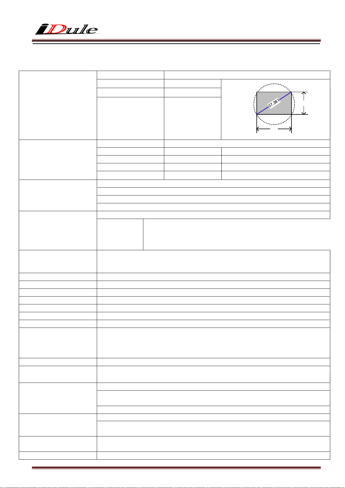
3.1. General Specification
(1) Image Sensor Device type
Effective pixel number
Unit cell size
Image circle
Diagonal length 37.361mm, Global Shutter type (GPIXEL GMAX3265)
9344(H) x 7000(V)
3.2μm(H) x 3.2μm(V)
Φ37.361mm
22.4
29.9
(単位:mm)
(2) Video Output Frequency Pixel Clock 80MHz
2Tap Base Configuration 2.4fps 4800(H) x 7056(V) with blanking
3Tap Base Configuration 3.1fps 3600(H) x 7056(V) with blanking
4Tap Medium Configuration 4.7fps 2400(H) x 7056(V) with blanking
8Tap Full Configuration 9.4fps 1200(H) x 7056(V) with blanking
(3) Video Output 2Tap Base Configuration
3Tap Base Configuration
4Tap Medium Configuration
8Tap Full Configuration (Initial Setting)
(4) Output Format Sensor AD 12bit
Camera Link Output
2Tap Base Configuration :8bit / 10bit / 12bit
3Tap Base Configuration :8bit
4Tap Medium Configuration:8bit / 10bit / 12bit
8Tap Full Configuration :8bit / 10bit
(5) Sensitivity B/W F16 2000lx
Color F11 2000lx
(at shutter speed 1/9.4s (OFF), Gain 0dB, Full Configuration mode)
(6) Power supply input voltage DC+12V±10% 12 pin connector (Initial Setting) / PoCL
(7) Power Consumption max 6.0W (at 8Tap Full Configuration)
(8) Dimensions H:55mm W:55mm D:45mm excluding projection
(9) Weight Approx. 185g
(10) Lens Mount M42 P1 mount (Cover glass or IR cut filter in none)
(11) Optical Axis Accuracy Refer to drawing for CMOS optical axis accuracy
(12) Gain Variable Range 0dB ~ +12dB (Guaranteed range)
(13) Shutter Speed Variable Range OFF(1/2.4s) ~ 1/12000s (2Tap Base Configuration)
OFF(1/3.1s) ~ 1/15000s (3Tap Base Configuration)
OFF(1/4.7s) ~ 1/20000s (4Tap Medium Configuration)
OFF(1/9.4s) ~1/25000s (8Tap Full Configuration)
(14) Trigger Shutter Mode Fixed shutter trigger mode / Pulse width shutter trigger mode
(15) Partial Scan Mono : Full frame ~ 1Line (1Line/Step) Color : Full frame ~ 2Line (2Line/Step) 1area
*Start position and Effective line : Even number only
(16) Safety/Quality Standards UL : Conform to UL Standard including materials and others.
CE : To be applied for EN55022:2006 Class A for Emission06
To be applied for EN61000-6-2:2005 for Immunity
RoHS : Confirm to RoHS
(17) Durability Vibration 20~200 Hz,98m/s2 (10G), X,Y and Z 3directions (120 min for each direction)
Shock No malfunction shall be occurred with 980m/s2 (100G) for ±X,±Y,and ±Z,
6 directions. (without package)
(18) Operation Environment Temperature -5 ~ +45℃
Humidity 20 ~ 80%RH with no condensation.
(19) Storage Environment Temperature -25 ~ +60℃ Humidity 20 ~ 80%RH with no condensation.
Page 5
3FFh
under
Both horizontal and vertical should be under
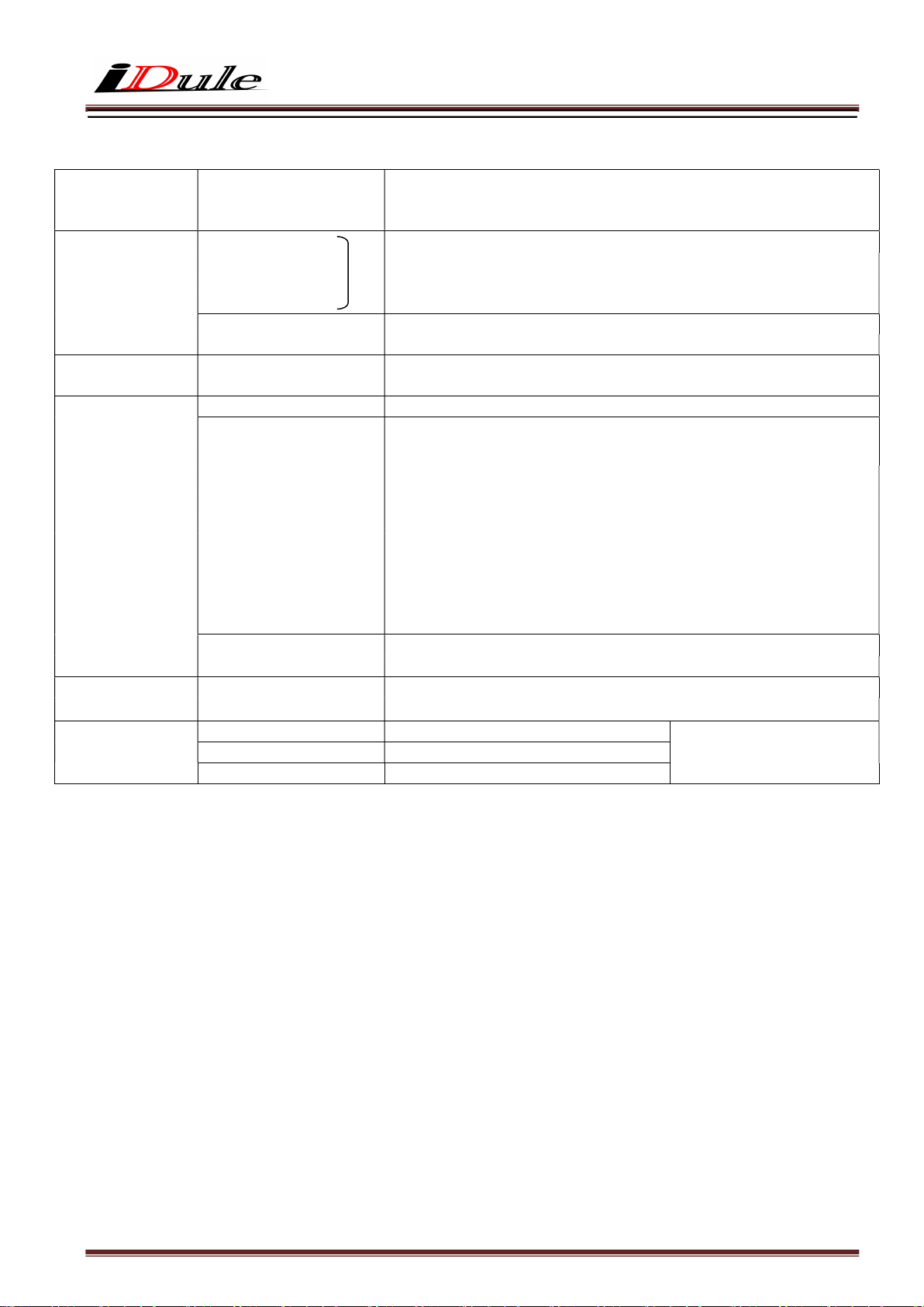
3.2. Camera Output Signal Specification
(1)Video Output Data Effective Video Output 9344(H) × 7000(V)
(at Full Frame Scan Mode)
*3Tap : 9360(H) x 7000(V)
9360(H) = 9344(H)+16pix(Black)
(2)Sync Signal Output LVAL Camera Link (LVDS)
FVAL
DVAL
SP
FVAL 12pin Connector 6pin (LVTTL)
Exposure 12pin Connector 10pin (LVTTL)
(3)Camera Control
Signal Input
CC2・CC3・CC4
Camera Link (LVDS) (No Function)
(4)Trigger Input Polarity Positive/Negative Selectable (Address 05h)
Pulse Width
2HD(Min) ~ (*)
2Tap Base Configuration : 1HD (60us)
3Tap Base Configuration : 1HD (45us)
4Tap Medium Configuration : 1HD (30us)
8Tap Full Configuration : 1HD (15us)
*The trigger input signal is sampled n times HD in the camera, and the
exposure time is processed n times HD. Trigger pulses shorter than 1 HD are
treated as 1 HD wide.
Functionally, no upper limitation is set but noises such as dark noises and
shadings might be noticeable at long time exposure.
CC1(Trigger Input) Camera Link (LVDS) (Address 06h)
12pin Connector(Trigger Input)
(5)Serial
Communication
SerTC
SerTFG (Serial to Frame Grabber)
(6)Video Signals White Clip Level
Setup Level
Dark Shading
12pin Connector 11pin Input (LVTTL)
Camera Link (LVDS)
(Serial to Camera)
(at Gain 0dB, 10bit)
002h
00Fh
Page 6
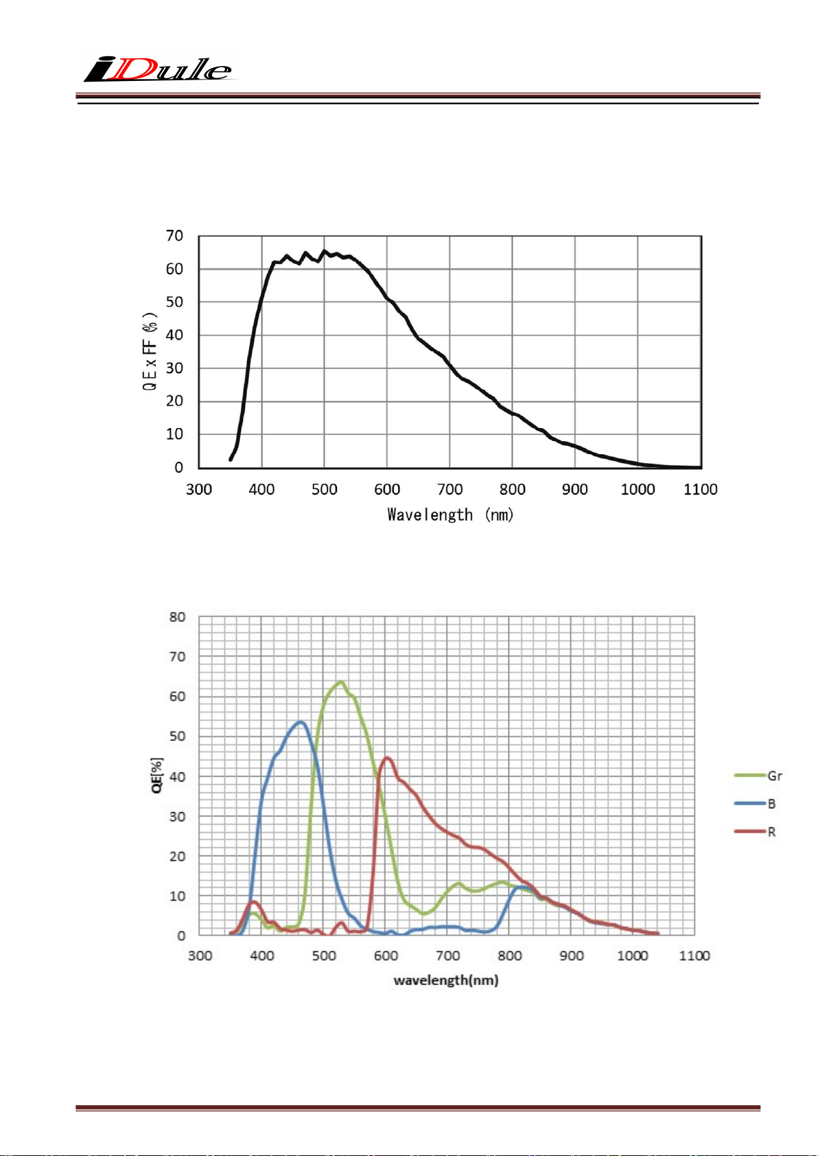
3.3. Spectral Response (Representative Value)
ID65MB-CL (B/W)
ID65MC-CL (Color)
Page 7
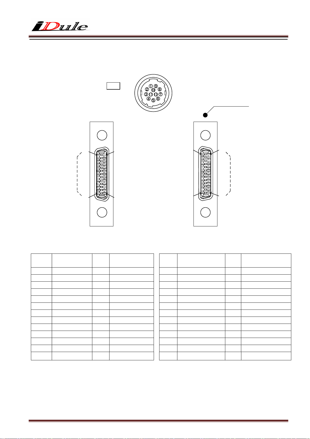
4. Connector
4.1.Camera Link Connector 12226-1100-00PL (SUMITOMO 3M)
Connector (P2) Connector (P1)
PIN
No
1 +12V(PoCL) 14 GND
2 Y0- 15 Y0+
3 Y1- 16 Y1+
4 Y2- 17 Y2+
5 Yclk- 18 Yclk+
6 Y3- 19 Y3+
7 100Ω 20 Terminated
8 Z0- 21 Z0+
9 Z1- 22 Z1+
10 Z2- 23 Z2+
11 Zclk- 24 Zclk+
12 Z3- 25 Z3+
13 GND 26 +12V(PoCL)
(Medium / Full Configuration)
26
14
Name PIN
(Power LED)
13
1
(P2)
No
Name
(CN1)
PIN
No
1 +12V(PoCL) 14 GND
2 X0- 15 X0+
3 X1- 16 X1+
4 X2- 17 X2+
5 Xclk- 18 Xclk+
6 X3- 19 X3+
7 SerTC+ 20 SerTC8 SerTFG- 21 SerTFG+
9 CC1- (Trigger IN -) 22 CC1+ (Trigger IN +)
10 CC2+ 23 CC211 CC3- 24 CC3+
12 CC4+ 25 CC413 GND 26 +12V(PoCL)
Base side
1
13
14
26
(P1)
Name PIN
(Base Configuration)
Name
No
Page 8
+5.0V(VCC)
4.2. Power LED
LED lights when the camera is operational. If the power is not supplied or the camera is broken, the LED will not light.
※ LED can be turned off (address 1Bh) by serial setting.
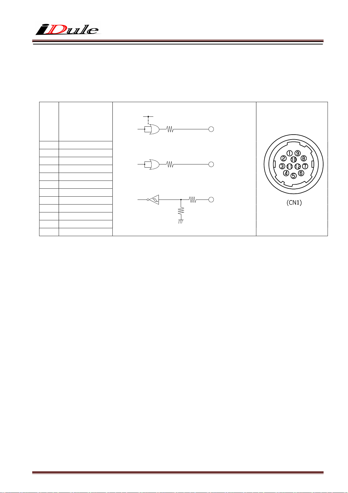
4.3. 12pin Connector HR10A-10R-12PB (HIROSE) (CN1)
IO(5V LVTTL)
PIN
No
Name
1 GND
2 Power in(DC+12V)
3 GND
4 NC
5 GND
6 FVAL out
7 NC
8 GND
9 NC
10 Exposure out
11 Trigger in
SN74LVC1G32(TI)
Voh:3.8V(Min)
Vol:0.55V(Max)
SN74LVC1G32(TI)
Voh:3.8V(Min)
Vol:0.55V(Max)
SN74LVC1G14(TI)
⊿
⊿
Vt-:0.71(Min)
Vt+:1.04V(Max)
100
100
Ω
Ω
100
Ω
1K
12pin
FVAL Output
6
Exposure Output
10
Ω
External Trigger Input
11
12 GND
4.4. Power input to camera
Camera rear 12pin connector (2pin) or Camera Link (PoCL) feeding is possible. (Because the power supply is diode-OR
connected, there is no problem even if it is powered simultaneously.)
Page 9
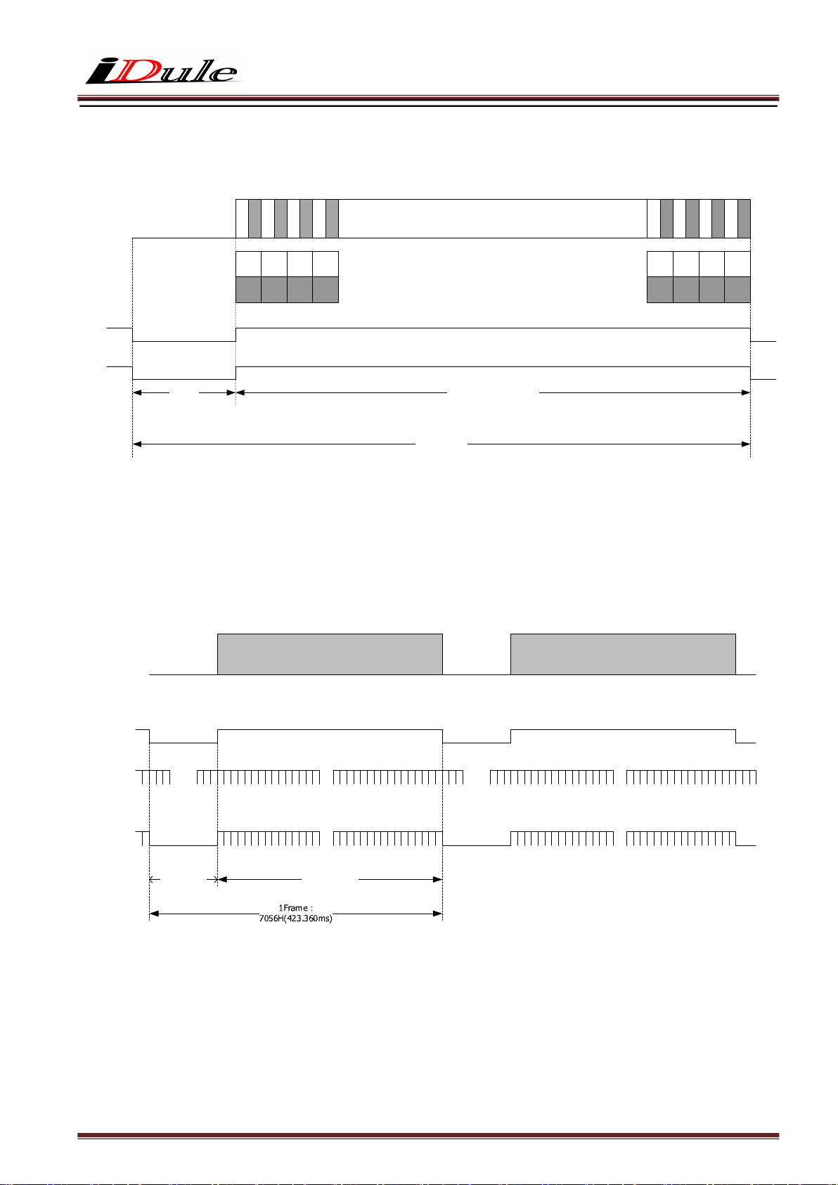
5. Timing Chart
5.1. Horizontal Synchronous Signals Timing (2Tap Base Configuration : 2.4fps )
0 1
Image Out
LVAL Out
DVAL Out
Camera Link Port A 0 2
Camera Link Port B
2 3 4 5 6 7
4 6
1 3 5 7
・ ・ ・ ・ ・ ・ ・
・ ・ ・ ・ ・ ・ ・ ・ ・ ・ ・ ・
・ ・ ・ ・ ・ ・ ・
Effective Data : 4672 CLK128 CLK
~
~
~
~
~
~
1H : 4800 CLK
5.2. Vertical Synchronous Signals Timing (2Tap Base Configuration : 2.4fps)
Image Out
FVAL Out
9
9
9
9
9
3
3
3
3
3
4
3
3
3
3
0
8
9
6
7
93
93
38
36
93
93
39
37
Camera Link CLK : 80MHz
9
9
9
3
3
3
4
1
93
40
93
41
4
4
2
3
93
42
93
43
LVAL Out
DVAL Out
~
~
V Blanking :
56H
~
~
~
0
~
~
Effective Line :
7000H
69
99
~
0
~
~
69
~
~
99
1H = 60us
Page 10
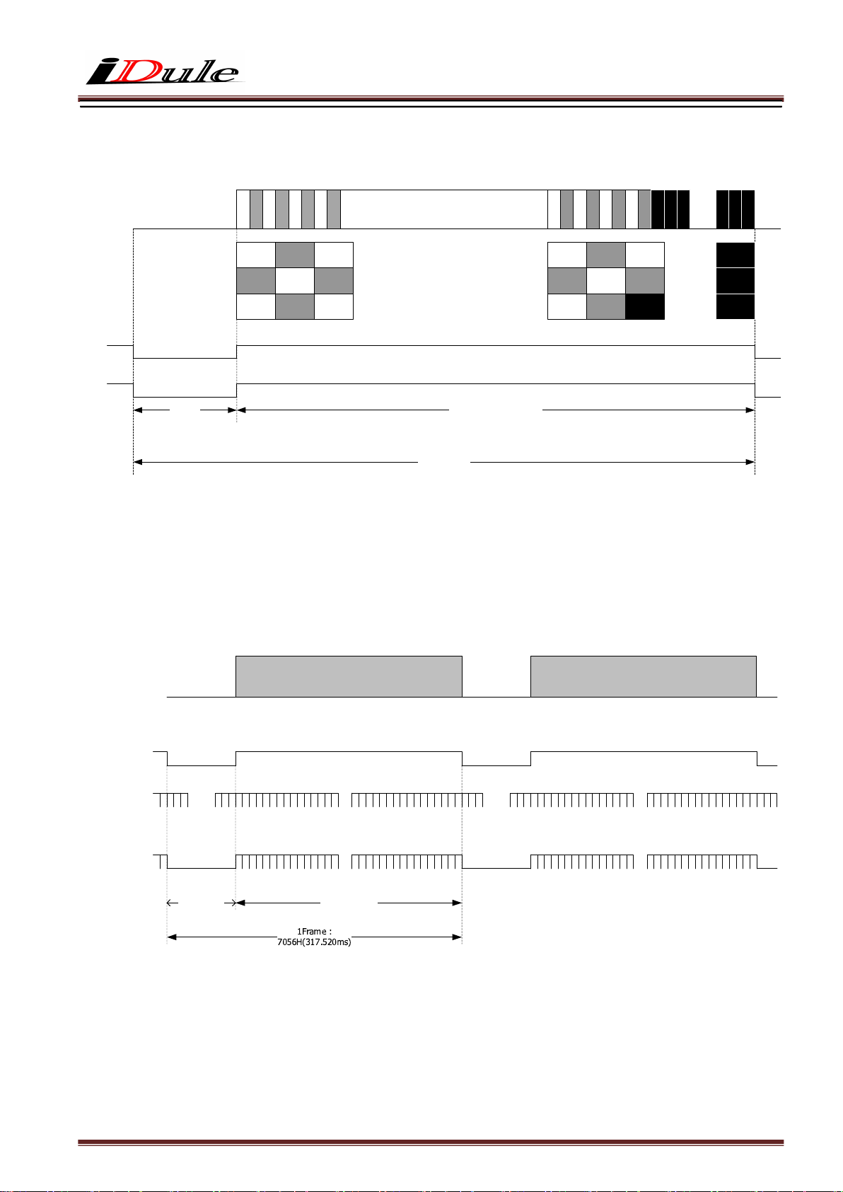
5.3. Horizontal Synchronous Signals Timing (3Tap Base Configuration : 3.1fps)
Image Out
Camera Link Port A
Camera Link Port B
Camera Link Port C
0 1 2 3 4 5 6 7
0
3
4
1
2
5
~
~
6
7
8
・ ・ ・ ・ ・ ・ ・ ・ ・ ・ ・ ・
・ ・ ・ ・ ・ ・ ・ ・ ・ ・ ・ ・
・ ・ ・ ・ ・ ・ ・
・ ・ ・ ・ ・ ・ ・
・ ・ ・ ・ ・ ・ ・
~
LVAL Out
~
9
3
3
3
3
3
4
3
3
3
3
0
8
9
6
7
93
93
36
39
93
93
40
37
93
93
38
41
9
9
3
3
4
4
2
1
9
3
3
3
3
4
4
4
4
3
4
5
6
93
42
93
43
93
44
9
9
9
3
5
7
~
~
3
5
8
9357
93
58
93
59
3
5
9
9
9
9
9
9
9
9
~
DVAL Out
Effective Data : 3120 CLK480 CLK
~
1H : 3600 CLK
5.4. Vertical Synchronous Signals Timing (3Tap Base Configuration : 3.1fps)
Image Out
FVAL Out
LVAL Out
DVAL Out
~
~
0
~
~
69
~
~
99
~
~
V Blanking :
56H
Effective Line :
7000H
Camera Link CLK : 80MHz
~
~
0
~
~
69
99
1H = 45us
Page 11
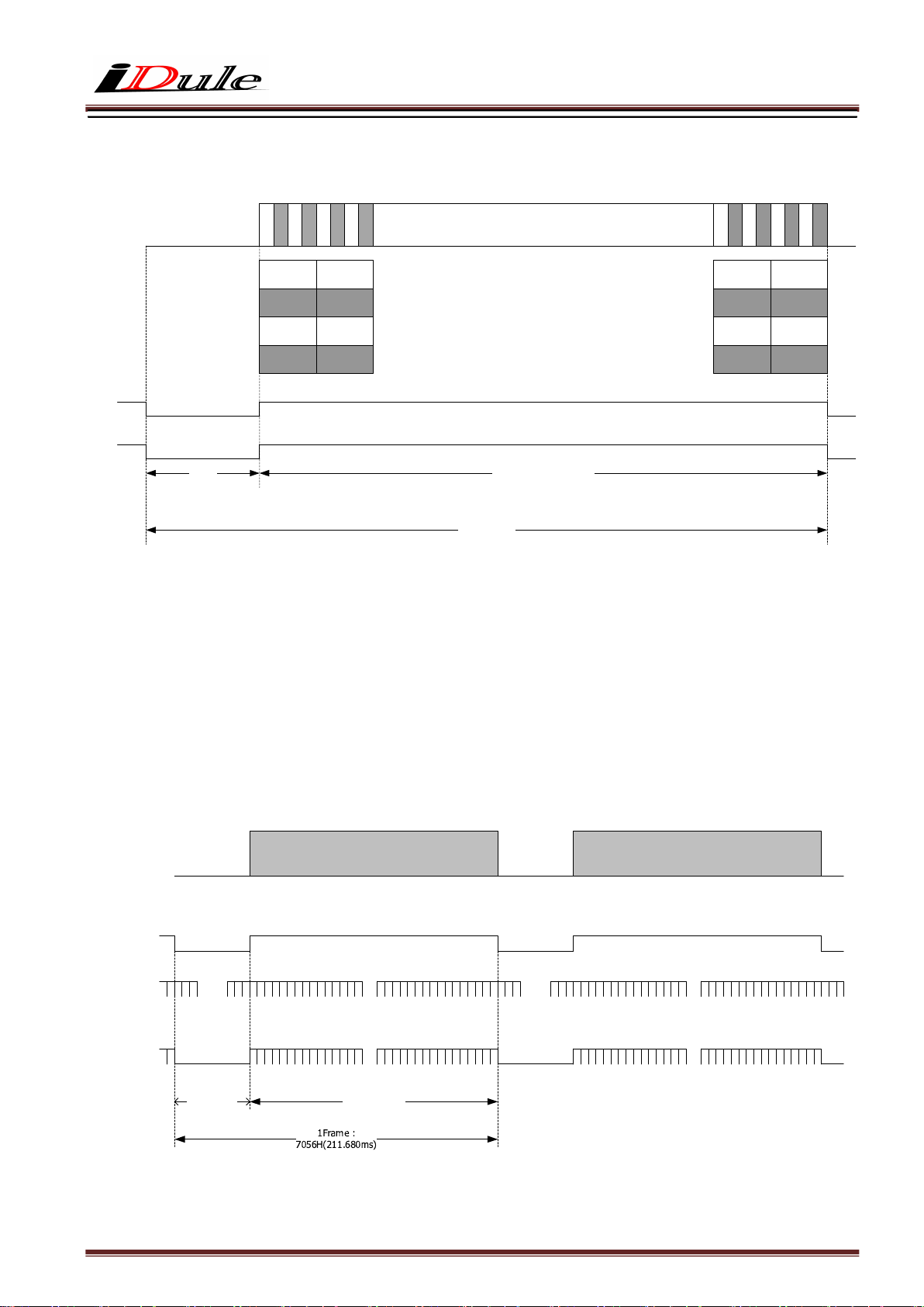
5.5. Horizontal Synchronous Signals Timing (4Tap Medium Configuration : 4.7fps)
Image Out
Camera Link Port A
Camera Link Port B
Camera Link Port C
Camera Link Port D
0 1 2 3 4 5 6 7
0
1
2
3
4
5
6
7
・ ・ ・ ・ ・ ・ ・
・ ・ ・ ・ ・ ・ ・ ・ ・ ・ ・ ・
・ ・ ・ ・ ・ ・ ・
・ ・ ・ ・ ・ ・ ・
・ ・ ・ ・ ・ ・ ・
~
~
~
LVAL Out
DVAL Out
Effective Data : 2336 CLK64 CLK
~
~
~
1H : 2400 CLK
5.6. Vertical Synchronous Signals Timing (4Tap Medium Configuration : 4.7fps)
Image Out
FVAL Out
9
9
9
9
9
3
3
3
3
3
4
3
3
3
3
0
8
9
6
7
93
36
93
37
93
38
93
39
Camera Link CLK : 80MHz
9
9
9
3
3
3
4
4
4
1
93
40
93
41
93
42
93
43
2
3
LVAL Out
DVAL Out
~
~
V Blanking :
56H
~
~
~
0
~
~
Effective Line :
7000H
69
99
~
0
~
~
69
~
~
99
1H = 30us
Page 12
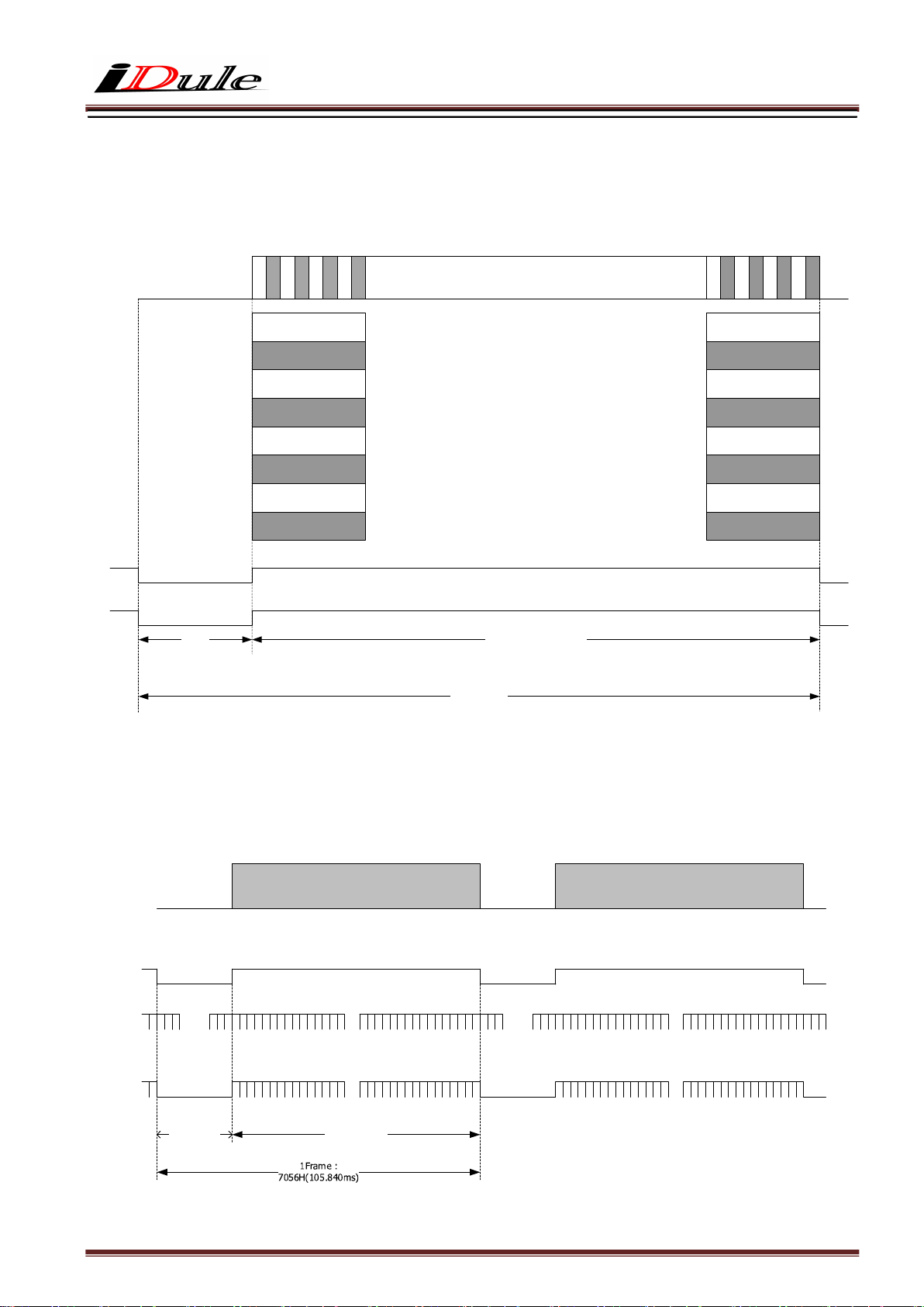
5.7. Horizontal Synchronous Signals Timing (8Tap Full Configuration : 9.4fps)
Image Out
Camera Link Port A
Camera Link Port B
Camera Link Port C
Camera Link Port D
Camera Link Port E
Camera Link Port F
Camera Link Port G
Camera Link Port H
0 1 2 3 4 5 6 7
0
1
2
3
4
5
6
7
・ ・ ・ ・ ・ ・ ・
・ ・ ・ ・ ・ ・ ・ ・ ・ ・ ・ ・
・ ・ ・ ・ ・ ・ ・ ・ ・ ・ ・ ・
・ ・ ・ ・ ・ ・ ・
・ ・ ・ ・ ・ ・ ・
・ ・ ・ ・ ・ ・ ・
・ ・ ・ ・ ・ ・ ・
・ ・ ・ ・ ・ ・ ・
・ ・ ・ ・ ・ ・ ・
・ ・ ・ ・ ・ ・ ・
~
~
~
LVAL Out
~
9
3
3
3
3
3
3
8
6
7
3
3
3
3
3
4
4
3
0
1
9
93
36
93
37
93
38
93
39
93
40
93
41
93
42
93
43
4
4
2
3
9
9
9
9
9
9
9
~
DVAL Out
Effective Data : 1168 CLK32 CLK
~
1H : 1200 CLK
5.8. Vertical Synchronous Signals Timing (8Tap Full Configuration : 9.4fps)
Image Out
FVAL Out
LVAL Out
~
~
~
~
~
~
DVAL Out
0
~
~
69
99
Camera Link CLK : 80MHz
~
~
0
~
~
69
99
V Blanking :
56H
Effective Line :
7000H
1H = 15us
Page 13
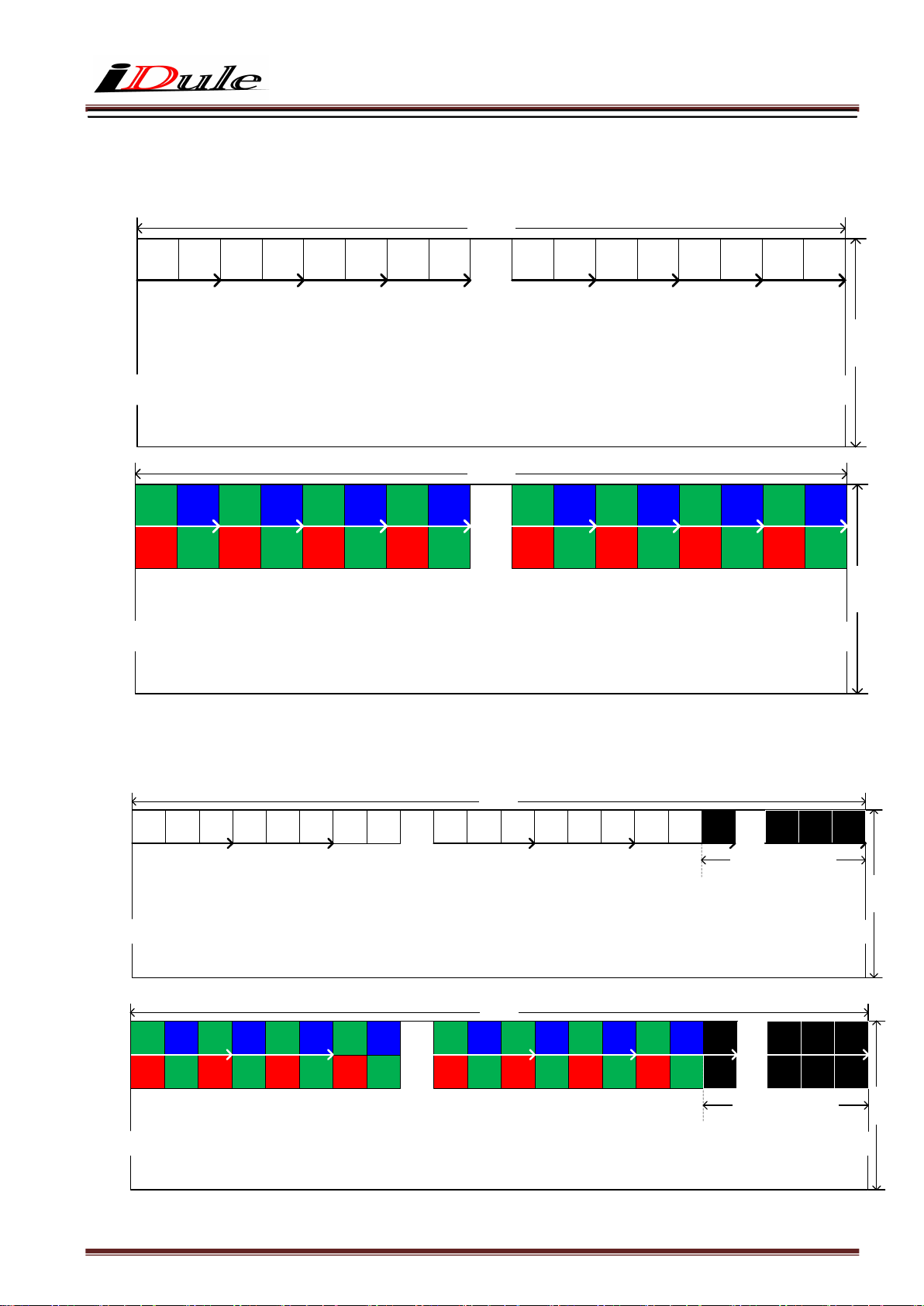
5.9. Image output format
(1) 2Tap Base Configuration : 2.4fps
D
D
D
D
0
1
2
D
3
4
~
~
G
B
G
B
G
0
1
2
3
4
R
G
R
G
R
0
1
2
3
4
~
~
(2) 3Tap Base Configuration : 3.1fps
D0D1D2D3D4D5D6D
~
~
G0B
R
0
1
G1R
G2B
2
3
G3R
G4B
5
G5R
4
~
~
D
5
B
5
G
5
G6B
6
9344(H)
D
D
6
・・・
7
D
9336D9337D9338D9339D9340D9341D9342D9343
7000(V)
~
~
9344(H)
B
G
B
6
7
G
9336
9337
G
B
9339
9338
G
B
9341
9340
G
B
9343
9342
・・・
G
R
G
6
7
5136(H)
D
・・・
7
9336D9337D9338D9339D9340D9341D9342D9343
R
9336
9337
R
G
9339
9338
R
G
9341
9340
D
9344
16pixel Black out
5136(H)
B
G
B
G
B
G
B
・・・
G
9336
R
9336
9337
G
9337
9338
R
9338
9339
G
9339
9340
R
9340
7
G
7
9341
G
9341
9342
R
9342
9343
G
9343
D
9344
D
9344
R
G
9342
D
・・・
9357D9358D9359
D
・・・
9357D9358D9359
D
・・・
9357D9358D9359
9343
7000(V)
~
~
7000(V)
~
~
7000(V)
16pixel Black out
~
~
Page 14
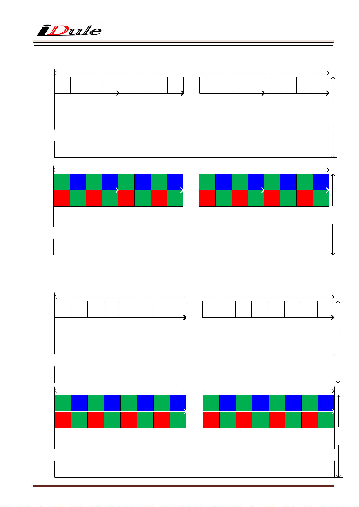
(3) 4Tap Medium Configuration : 4.7fps
D
D
D
D
0
1
2
3
~
~
G
B
G
B
0
1
2
3
R
G
R
G
0
1
2
3
~
~
(4) 8Tap Full Configuration : 9.4fps
D
D
D
D
0
1
2
3
~
~
G
B
G
B
0
1
2
3
R
G
R
G
0
1
2
3
~
~
9344(H)
D
D
D
D
4
5
6
G
B
G
4
5
6
R
G
R
4
5
6
D
D
D
4
5
6
G
B
G
4
5
6
R
G
R
4
5
6
7
B
7
G
7
D
7
B
7
G
7
・・・
9344(H)
・・・
9344(H)
9344(H)
D
9336D9337D9338D9339D9340D9341D9342D9343
B
G
B
G
B
G
9341
9340
9339
9338
9337
9336
G
R
G
R
G
R
9341
9340
9339
9338
9337
9336
・・・
・・・
D
9336D9337D9338D9339D9340D9341D9342D9343
B
G
B
G
B
G
9341
9340
9339
9338
9337
9336
G
R
G
R
G
R
9341
9340
9339
9338
9337
9336
G
9342
R
9342
9342
9342
7000(V)
~
~
B
9343
G
9343
7000(V)
~
~
7000(V)
~
~
B
G
9343
G
R
9343
7000(V)
~
~
Page 15
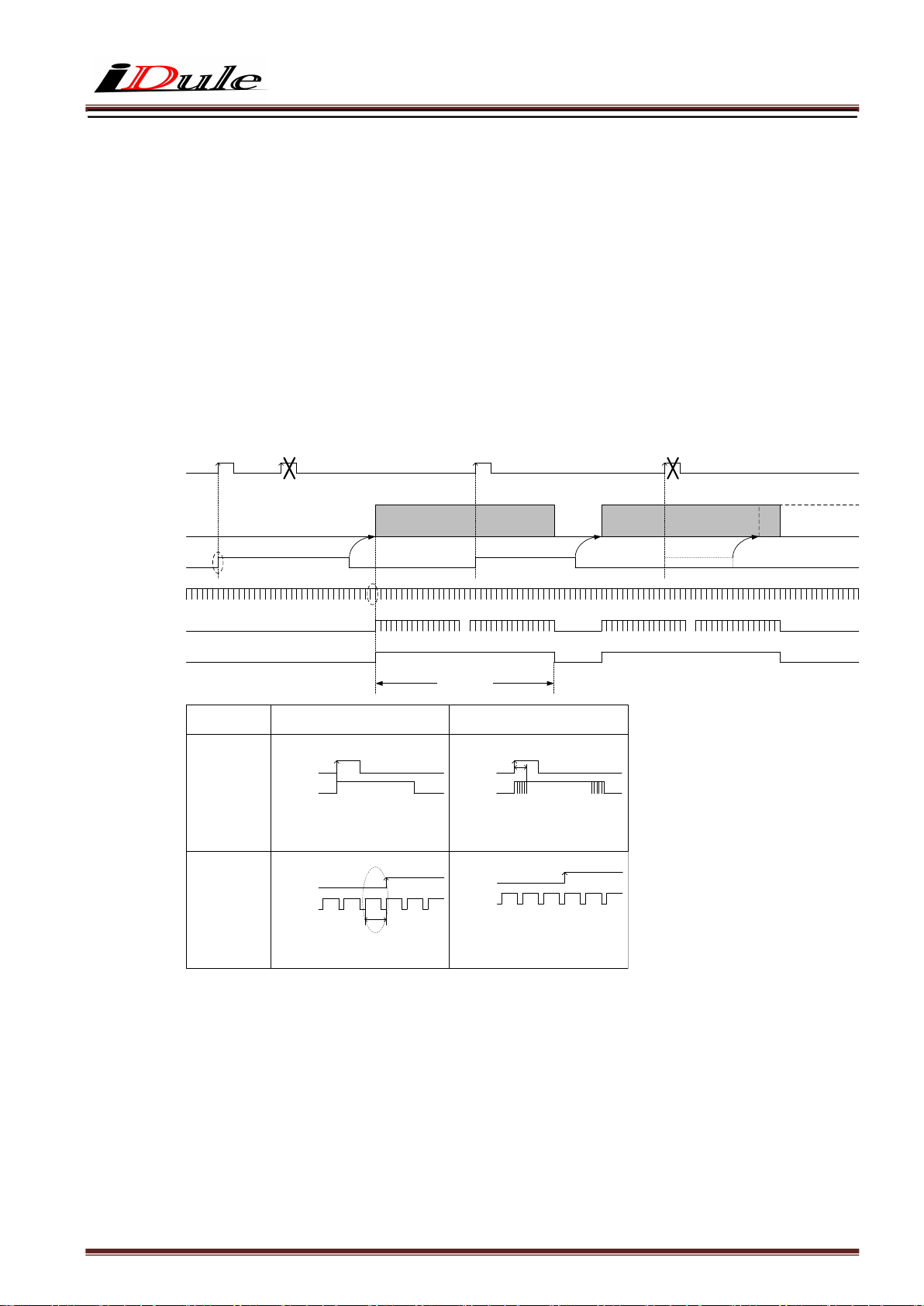
5.10. Fixed Trigger Shutter Mode
□ This is the mode to start exposure with external input trigger signals, and set the exposure time with serial
commands.
□ Delay time (Exposure Time Delay) from detecting trigger edge in the camera to starting exposure.
□ Triggers can be accepted even when outputting video signals.
However, trigger signals for exposure to start the next video output prior to the completion of video transmission
for the prior video output signals can not be accepted.
□ Trigger input during exposure time should be ignored. (Refer to the below A)
□ The delay time is fixed with the Trigger Hsync Mode ON.
However, if you use inputting the trigger signals for exposure to start the next video output prior ,
the line noise appears occasionally by the trigger timing.
Exposure O ut
Camera Link : SP out
12pin CN : 10pin out
TRIG IN
Image Out
LVAL Out
DVAL Out
FVAL Out
(a)
Trigger Hsync mode :
(Address:
17h)
Exposure Time
Delay
(a)
LVAL signal before
rising of FVAL
(b)
(A)
(Address:0
1h)
(b)
OFF(Data:0)
Exposure Delay 0
TRIG IN
Exposure
FVAL out
LVAL out
The length of LVAL of point (b) is variable.
(b)
~
~
Effective Line :
5120H
TRIG IN
Exposure
2Tap :
3Tap :
4Tap :
8Tap :
FVAL out
LVAL out
(Address:0
1h)
ON(Data:1) 【Factory settin g
Exposure Delay max1HD
max 34.207us
max 25.655us
max 17.103us
max 8.552us
LVAL length is always fixed.
】
(B)
(Address:0
1h)
~
~
Page 16
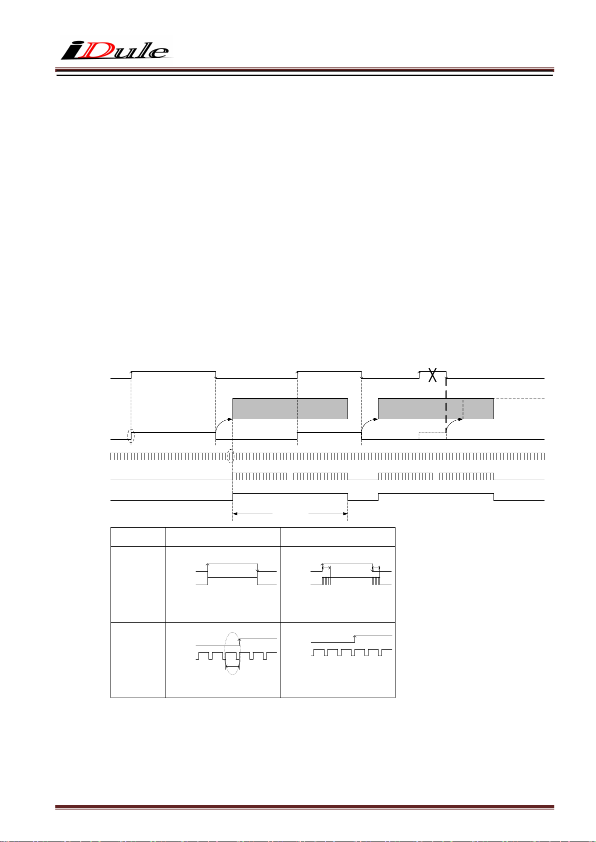
5.11. Pulse Width Trigger Shutter Mode
□ This is the mode to start exposure with external input trigger signals, and set the exposure time with
pulse width of the trigger signals.
□ Delay time (Exposure Time Delay) from detecting trigger edge in the camera to starting exposure, and from
detecting trigger end edge to completing exposure.
□ Pulse width is min. 2HD (min) to approx. 2 frames.
Functionally, there is no upper limitation, but noises such as dark noises and shadings may be noticeable
at long time exposure.
□ Triggers can be accepted even when outputting video signals.
However, trigger signals for exposure to start the next video output prior to the completion of video transmission
for the prior video output signals can not be accepted.
□ The delay time is fixed with the Trigger Hsync Mode ON.
However, if you use inputting the trigger signals for exposure to start the next video output prior ,
the line noise appears occasionally by the trigger timing.
Exposure O ut
Camera Link :SP out
12pin CN:10pin out
TRIG IN
Image Out
LVAL Out
DVAL Out
FVAL Out
(a)
Trigger Hsync mode :
(Address:
17h)
Exposure Time
Delay
(a)
LVAL signal before
rising of FVAL
(b)
(b)
OFF(Data:0)
Exposure Delay 0
TRIG IN
Exposure
FVAL out
LVAL out
The length of LVAL of point (b) is variable.
(b)
~
~
Effective Line :
5120H
TRIG IN
Exposure
2Tap :
3Tap :
4Tap :
8Tap :
FVAL out
LVAL out
ON(Data:1) 【Factory settin g
Exposure Delay max1HD
max 34.207us
max 25.655us
max 17.103us
max 8.552us
LVAL length is always fixed.
】
(A)
~
~
Page 17
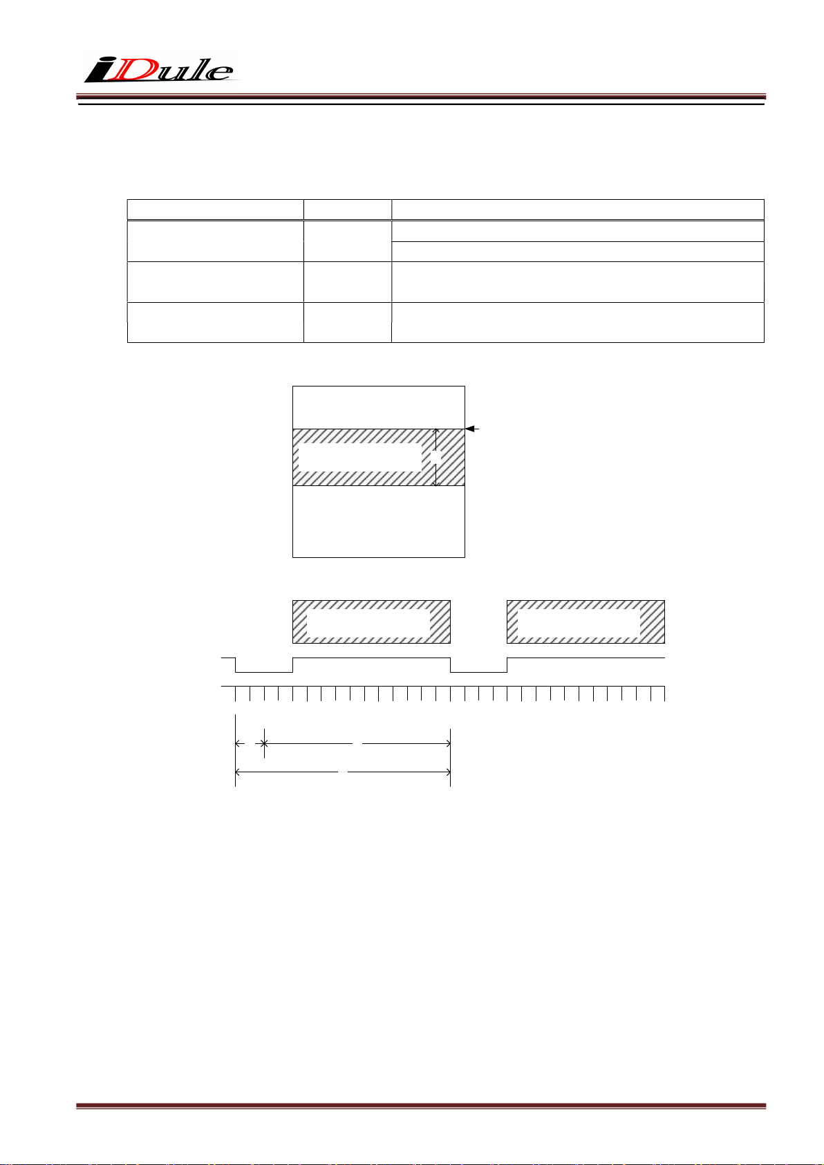
6. Partial Scan Mode
□ 1 partial area can be set by serial commands.
Function Address(Hex)
Partial scan mode
ON/OFF
Partial scan
Start position
Partial scan
Effective line
Image Out
FVAL
LVAL
①
(Example : Effective line :20 lines)
① : 56 lines fixed
② : Partial Area : 20 lines
③ : Total frame line : 76 lines
08
40-41
50-51
Partial Scan Effective Line
(Address : 50-51h)
Partial Scan Effective Line Partial Scan Effective Line
③
Partial scan
②
Full frame scan mode (00h)
Partial scan mode (01h)
mono
color
mono
color
0
Partial Scan Start Posit ion
(Address : 40-41h)
②
5119
min:0(0000h) ~ max:6999(1B57h)
min:0(0000h) ~ max:6998(1B56h)
min:1(0001h) ~ max:7000(1B58h)
min:2(0002h) ~ max:7000(1B58h)
Data(Hex)
Page 18
□ When setting several partial scan areas, please set the start position and effective lines trying not to
overlap the areas.
□ When setting several areas, please set the areas in the numerial order of start position.
□ Entire frame line numbers = V blanking line numbers (56H fixed) +Partial effective lines
Note that “Sum total of partial effective line numbers (expect V blanking lines) < 7000 should be met.
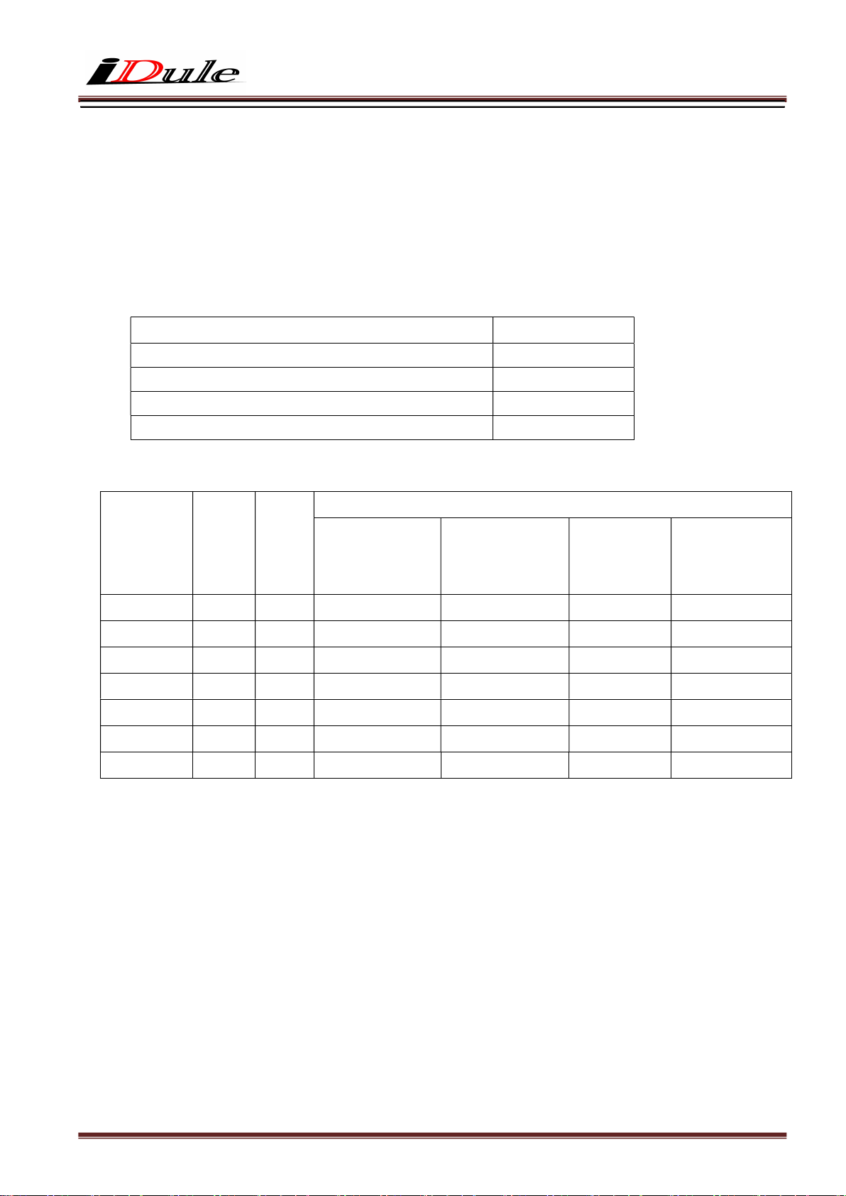
□ Frame rate = 1 / (Entire frame line numbers × Time for 1 line)
Camera Mode Time for 1 Line
2Tap Base Configuration 60us
3Tap Base Configuration 45us
4Tap Medium Configuration 30us
8Tap Full Configuration 15us
□ Example
Effective
Line
Number
Frame
Total
Line
Number
2Tap
Base
3Tap
Base
Frame Rate (fps)
4Tap
Medium
8Tap
Full
Mono(min) 1 57 292.4 389.9 584.8 1169.6
Color(min) 2 58 287.4 383.1 574.7 1149.4
Vertical:VGA
Vertical:XGA
480 536 31.1 41.5 62.2 124.4
768 824 20.2 27.0 40.5 80.9
Vertical:SXGA 1024 1080 15.4 20.6 30.9 61.7
Vertical:UXGA 1200 1256 13.3 17.7 26.5 53.1
OFF(Max) 7000 7056 2.4 3.1 4.7 9.4
Page 19
left and right
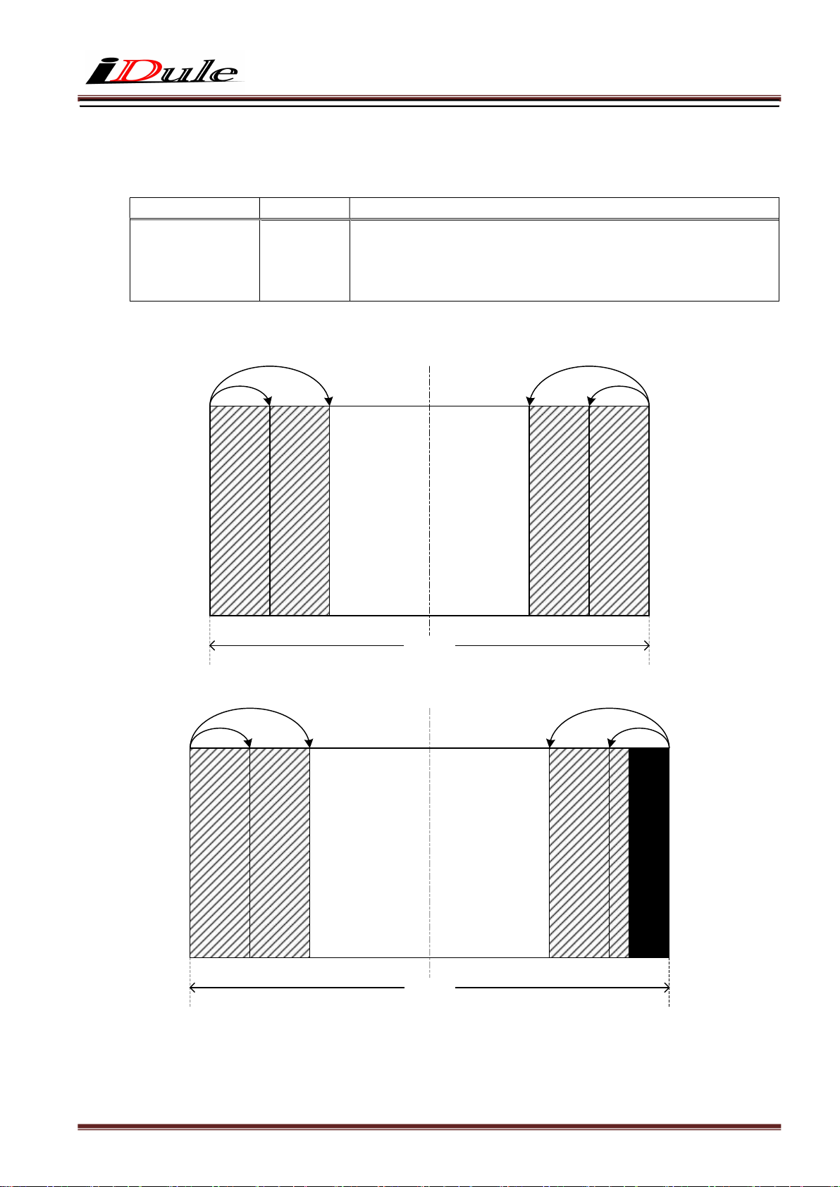
7. Horizontal cutout function
It is possible to cut out the left and right in the horizontal direction with 24 pixels x n. The frame rate does not
change even if you cut out the horizontal direction.
Function Address(Hex)
min:0(00h) ~ max:194(C2h)
Horizontal cutout 16
0
0
24
24
min:0=Full frame, 1=left and right 24pixel cut, max:106=
4656pixel cut
Cut size (pixel) = setting value x 24
48
2Tap Base, 4Tap Medium,
8Tap Full
9344(H)
48
3Tap Base
9360(H)
Data(Hex)
9295
9311
9319
9343
9335
9359
Page 20
8. Remote Communication
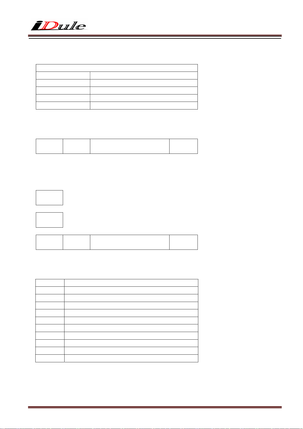
Via camera link cable, the camera can be controlled.
Communication Settings
Baud Rate
Data
Stop bit
Parity
XON / XOFF
:115200bps (fixed)
:8bit
:1bit
:None
:No Control
・ Send Command Format (Host to Camera)
If send a command, set the command and parameter between STX and ETX.
STX
(02H)
command
(2byte)
parameter (ASCII code)
(20H-7FH)
ETX
(03H)
・ Return Command Format (Camera to Host)
Normally, a camera returns a control code which is ACK or NAK.
If return value has a text message, the message is between STX and ETX.
ACK
・・・ Succeed
(06H)
NAK
・・・ Fail
(15H)
STX
(02H)
command
(2byte)
parameter (ASCII code)
(2FH- 7FH)
ETX
(03H)
・ Command List
Command Function
SR Set some values of resister
GR Get some values of resister
SU Set a user’s data
GU Get a user’s data
CS Save all configurations
CR Restore all configurations
QM Get a model name
QS Get a serial number
QV Get a firmware version
QE Get a detail of error information
・・・ return message
Page 21
8.1. Command Specifications
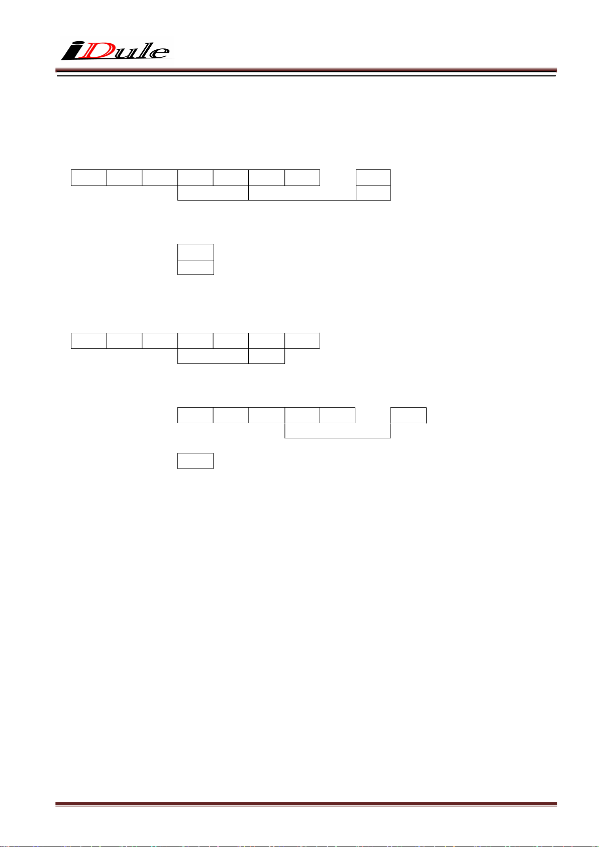
1) Set some values of resister
【Command】 Set : Resister
STX S R (a) (a) (d) (d)
・・・
ETX
Address
Data (Variable-length:max 16 address)
【Return Value】
Succeed
Fail
・・・
・・・
ACK
NAK
2) Get some value of resister
【Command】 Get : Resister
STX G R (a) (a) (d) ETX
Address
Number of data acquisition (optional)
【Return value】
Succeed
・・・
STX A R (d) (d)
・・・
ETX
Fail
・・・
NAK
Data (Data length depends on the number of acquisitions)
【Remarks】
The command gets some value of register of the specified address. The number of the acquisition is between
’0’ and ’F’( Hexadecimal ).
If appoint ’0’ at the address, the command send data of 16 address. If the command is omitted at the address,
the command send an address.
Page 22
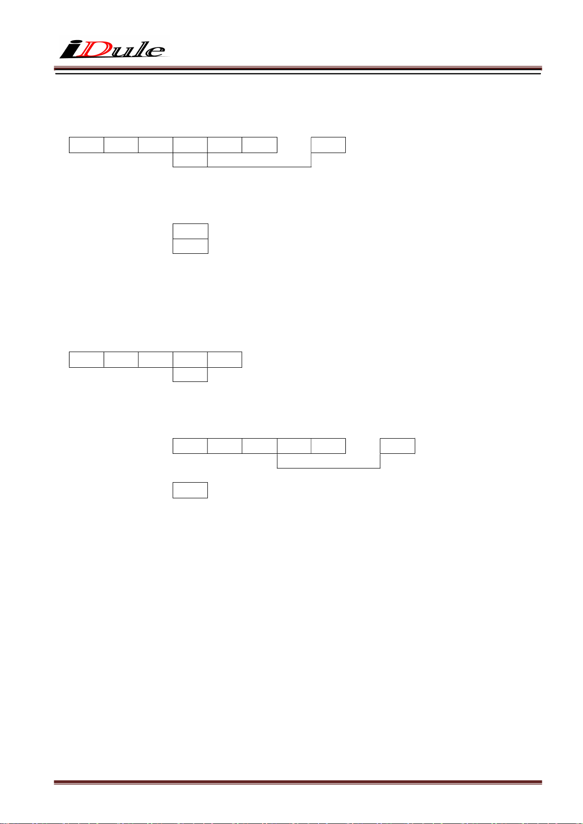
3) Set User’s data
【Command】 Set : User’s data
STX S U (n)
・・・
ETX
Table No.
User’s data (fixed length :16byte)
(0~3)
【Return Value】
Succeed
Fail
・・・
・・・
ACK
NAK
【Remarks】
The commands, sets free data on the specified register, and can use 4 tables (1 table : 16 characters).
4) Get User’s data
【Command】 Get : User’s data
STX G U 0 ETX
Table No.
(0~3)
【Response】
Succeed
・・・
STX A U (d) (d)
・・・
ETX
User’s data (fixed length : 16byte)
Fail
・・・
NAK
Page 23
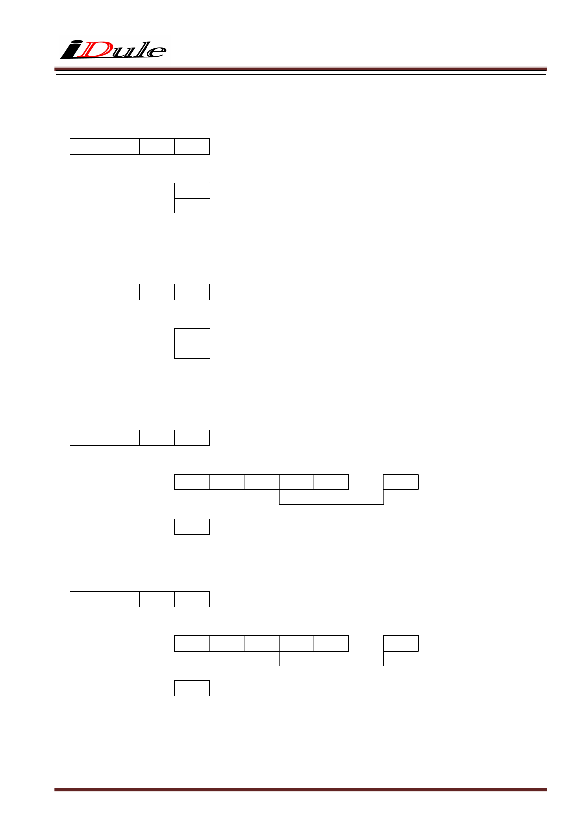
5) Save all configurations
【Command】 Configuration : Save
STX C S ETX
【Return Value】
Succeed
Fail
・・・
・・・
ACK
NAK
6) Restore all configurations
【Command】 Configuration : Restore
STX C R ETX
【Return Value】
Succeed
Fail
・・・
・・・
ACK
NAK
7) Get a model name
【Command】 Query : Model name
STX Q M ETX
【Return Value】
Succeed
・・・
STX R M (d) (d)
・・・
Fail
・・・
NAK
Model name (Fixed length:16byte)
8) Get a serial number
【Command】 Query : Serial number
STX Q S ETX
【Return Value】
Succeed
・・・
STX R S (d) (d)
・・・
Fail
・・・
NAK
Serial Number(Fixed length:8byte)
ETX
ETX
Page 24
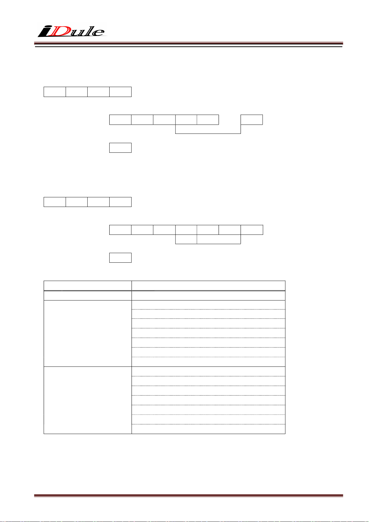
9) Get a firmware version
【Command】 Query : Version
STX Q V ETX
【Return Value】
Succeed
・・・
STX R V (d) (d)
・・・
Fail
・・・
NAK
Version information (fixed length:8byte)
10) Get a detail of error information
【Command】 Query : Error
STX Q E ETX
【Return Value】
Succeed
・・・
STX R E (d) (d) (d) ETX
Kind
Fail
・・・
NAK
Detal
Kind Detail
0:
No Error
1:
Communication Protocol
Error
2:
Internal Control Error
00:
00:
01:
02:
03:
04:
05:
06:
00:
01:
02:
03:
04:
05:
06:
Normal result
The command is undefined.
The command length is more than defined.
The address is undefined.
The value of data is undefined.
The length is more than defined.
The table number is undefined.
The string of user data was abnormal.
Internal control is abnormal.
A read only address was written by the command.
A protected address was written by the command.
Out of range address was written by the command.
The selected table number is abnormal.
The value of the man acquisition area is abnormal.
A function is not implemented.
ETX
Page 25
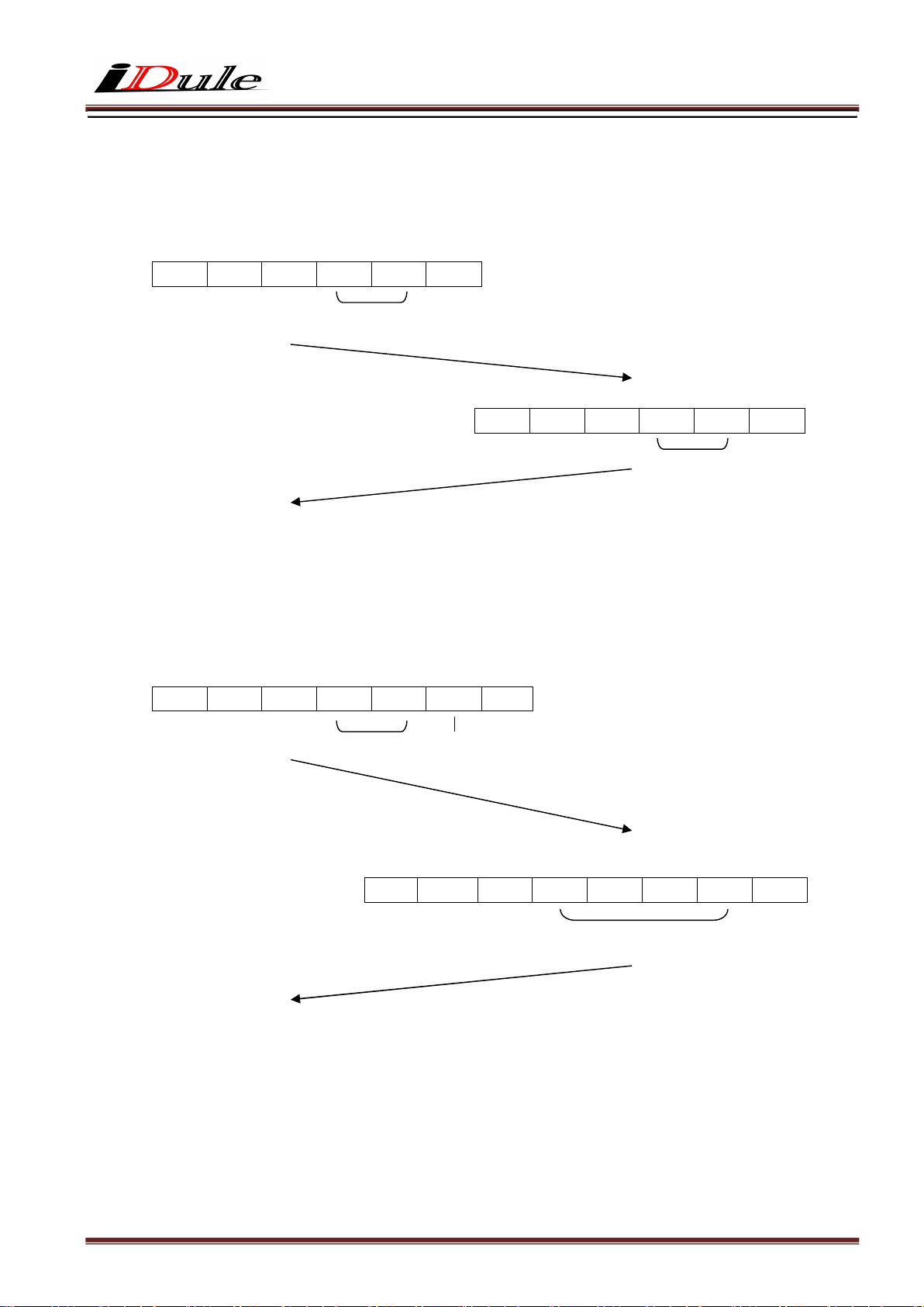
8.2. Control Example
1) How to check trigger shutter mode. ( The command gets a value from address 04)
【Send Command】
STX G R 0 4 ETX
Address 04
【Return value form camera】
STX A R 0 1 ETX
Data 01
【Receive Return Value】
The camera is working with a trigger shutter mode, because the command received a 01 from the camera.
2) How to check trigger shutter mode. ( The command gets consecutive 2 bytes values from address 20)
【Send Command】
STX G R 2 0 2 ETX
Address20 2Byte
【Receive return value】
STX A R F F 0 2 ETX
Data 02FF
【Receive return value】
The shutter mode of camera is working +12dB, because the command received a 02FF(767)
from the camera.
Page 26
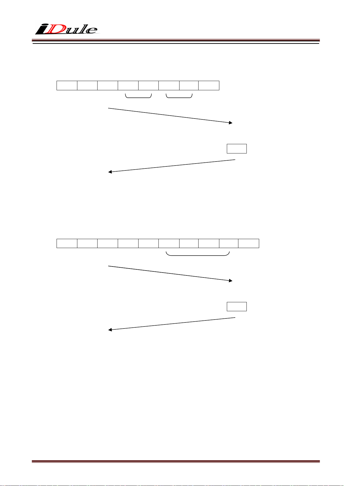
3) How to set partial scan mode. (The command sets 01 for address 08)
【Send Command】
STX S R 0 8 0 1 ETX
Address 08 Data 01
【Return value form camera】
ACK
【Receive Return Value】
The command finished normally, because the command received ACK from the camera.
4) How to set 01FF for manual shutter. (The command set 01FF for address 24)
【Send Command】
STX S R 2 4 F F 0 1 ETX
Address 24 Data 01FF
【Return value form camera】
ACK
【Receive Return Value】
The command finished normally, because the command received ACK from the camera.
Page 27
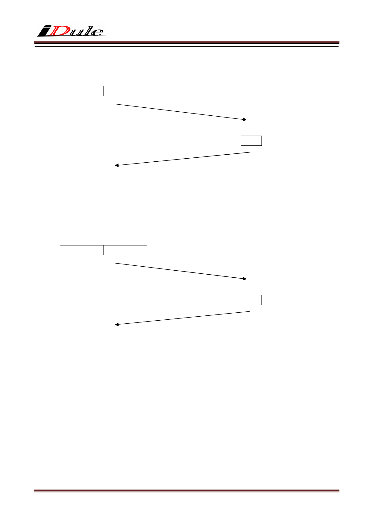
5) How to save configurations of a camera. (The command send CS)
【Send Command】
STX C S ETX
【Return value form camera】
ACK
【Receive Return Value】
The command finished normally, because the command received ACK from the camera.
6) How to restore the camera to initial settings. (The command send CR)
【Send Command】
STX C R ETX
【Return value form camera】
ACK
【Receive Return Value】
The command finished normally, because the command received ACK from the camera.
Page 28
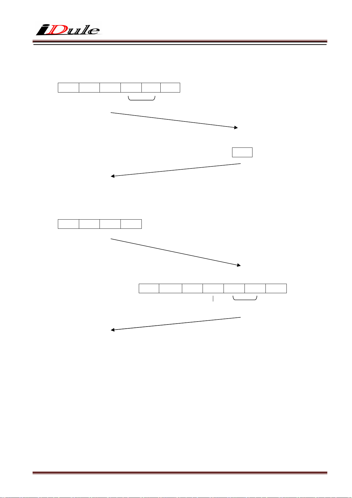
7) How to get detail of a communication error.
【Send Command】
STX G R @ 0 ETX
Set the address invalid value
【Return value form camera】
NAK
【Receive return value】
The command finished abnormally, because the command received ‘NAK’ from the camera.
When the command did not finish normally, retry to send command or send to get detail of a detail error command.
【Send Command】
STX Q E ETX
【Return value form camera】
STX R E 1 0 2 ETX
Kind1 Detail 02
【Receive Return Value】
The ‘GR’ command accessed invalid address , because the error command received kind ‘1’ and detail ‘02’.
Page 29
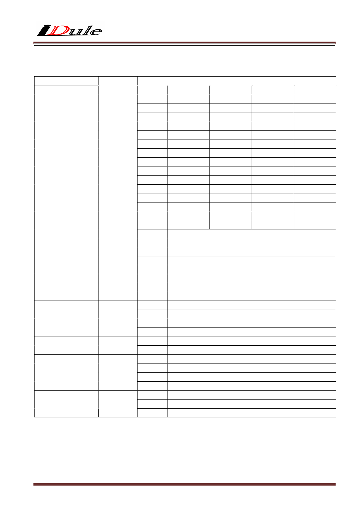
9. Function Setting
Function Address(Hex)
Preset shutter 01
Preset white balance
(color model)
Trigger shutter 04
Trigger polarity 05
Trigger input 06
Partial scan
ON/OFF
Output mode 0A
Output bit 0B
Data(Hex)
02
08
2Tap Base 3Tap Base 4Tap Medium
00:
01:
02:
03:
04:
05:
06:
07:
08:
09:
0A:
0B:
0C:
0D:
0E:
0F:
00:
01:
02:
03:
00:
01:
02:
00:
01:
00:
01:
00:
01:
00:
01:
02:
03:
00:
01:
02:
1/2.4s(OFF) 1/3.1s(OFF) 1/4.7s(OFF) 1/9.4s(OFF)
1/5s 1/6s 1/9s 1/19s
1/9s 1/12s 1/19s 1/38s
1/19s 1/25s 1/38s 1/76s
1/38s 1/50s 1/76s 1/150s
1/76s 1/100s 1/150s 1/300s
1/150s 1/200s 1/300s 1/600s
1/300s 1/400s 1/600s 1/1200s
1/600s 1/800s 1/1200s 1/2500s
1/1200s 1/1500s 1/2500s 1/5000s
1/2500s 1/3500s 1/5000s 1/9000s
1/4000s 1/5000s 1/7000s 1/12000s
1/5000s 1/7000s 1/9000s 1/15000s
1/7000s 1/9000s 1/12000s 1/20000s
1/12000s 1/15000s 1/20000s 1/25000s
Manual shutter (Address24-25h)
THRU
3200K(IRcut filter :C5000)
THRU(Spare)
Manual
Normal (Trigger OFF)
Fixed trigger shutter mode (Address 01)
Pulse width trigger shutter mode
Positive
Negative
CC1
12pin connector (11pin)
Full frame
Partial scan
8Tap Full Configuration
4Tap Medium Configuration
3Tap Base Configuration
2Tap Base Configuration
8bit 8Tap, 4Tap, 3Tap, 2Tap Configuration
10bit 8Tap, 4Tap, 2Tap Configuration
12bit 4Tap, 2Tap Configuration
8Tap Full
Page 30
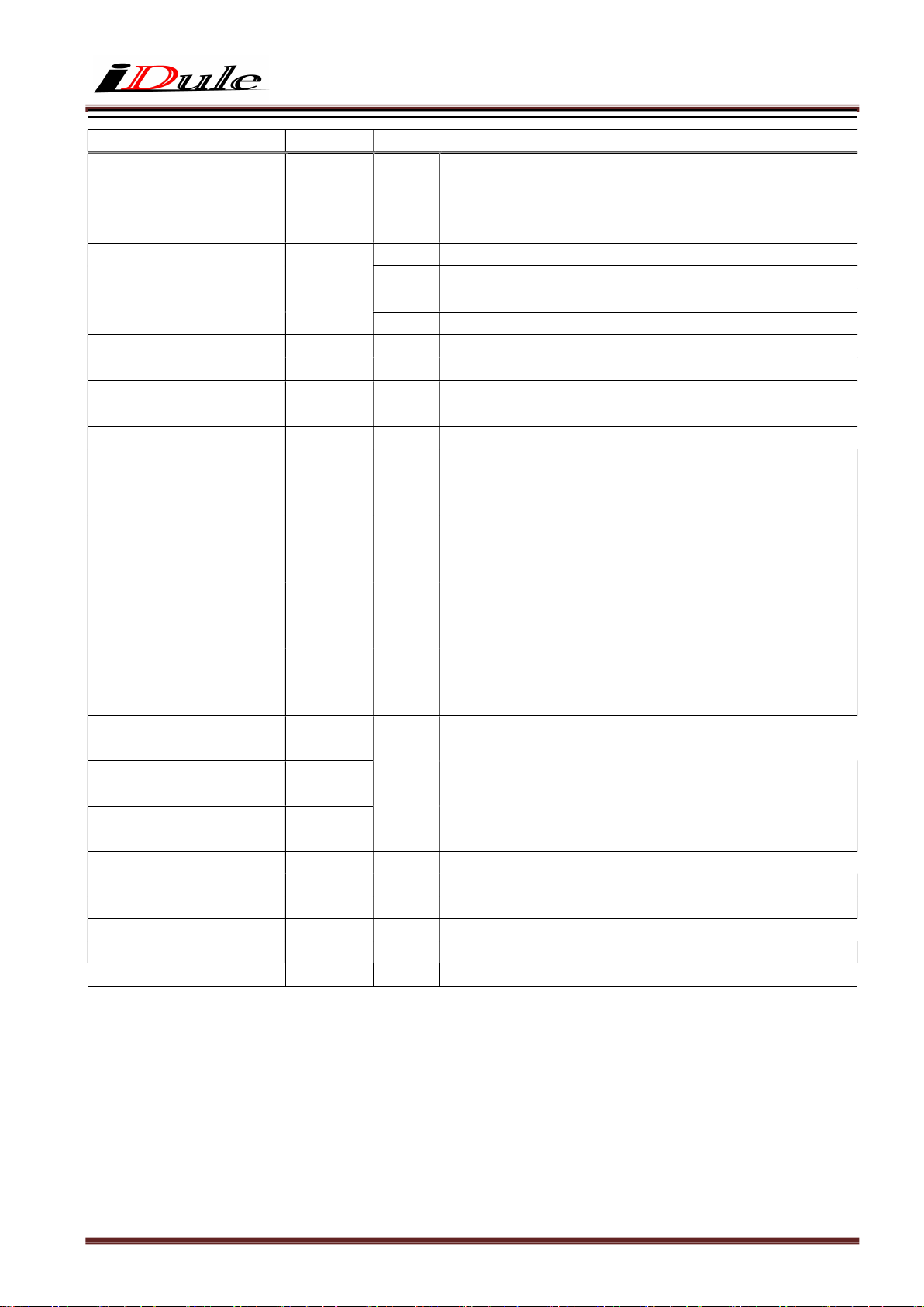
Function
Address(Hex)
Data(Hex)
min:0(00h) ~ max:194(C2h)
Horizontal cutout 16
LL:
min:0=Full frame, 1=left and right 24pixel cut, max:194=left and
right 4656pixel cut
Cut size(pixel) = setting value x 24
Trigger Hsync mode 17
Image flip 18
LED ON/OFF 1B
Manual gain 20-21
00:
01:
00:
01:
00:
01:
LLHH:
OFF
ON
Normal
Flip
OFF
ON
min:0(0000h) ~ max:767(02FFh)
x1(0dB) ~ x4(+12dB) Gain = (setting value+256) / 256
min:0(0000h) ~ max:5119(13FFh)
2Tap Base Configuration :
Exposure time = 22.25us + (7000 - (setting value)) x 60us
min:0=420.0ms, max:5119=82.3us
3Tap Base Configuration :
Exposure time = 22.25us + (7000 - (setting value)) x 45us
Manual shutter 24-25
LLHH:
min:0=315.0ms, max:5119=67.3us
4Tap Medium Configuration :
Exposure time = 22.25us + (7000 - (setting value)) x 30us
min:0=210.0ms, max:5119=52.3us
8Tap Full Configuration :
Exposure time = 22.25us + (7000- (setting value)) x 15us
min:0=105.0ms, max:5119=37.3us
Manual white balance R
(color model)
Manual white balance B
(color model)
Manual white balance G
(color model)
Partial scan
Start position
Partial scan
Effective line
28-29
2A-2B
2C-2D
40-41
50-51
LLHH:
LLHH:
LLHH:
min:0(0000h) ~ max:767(02FFh)
x1(0dB) ~ x4(+12dB) Gain = (setting value+256) / 256
mono
color
min:0(0000h) ~ max:6999(1B57h)
min:0(0000h) ~ max:6998(1B56h)
mono
color
min:1(0001h) ~ max:7000(1B58h)
min:2(0002h) ~ max:7000(1B58h)
※ LLHH : The data set with 2 Byte shall be set with Low Byte first, then set with High Byte.
< Example> Manual Shutter (Address 24-25h) ->6671(1A0FH)
STX SR 24 0F 1A ETX
Page 31
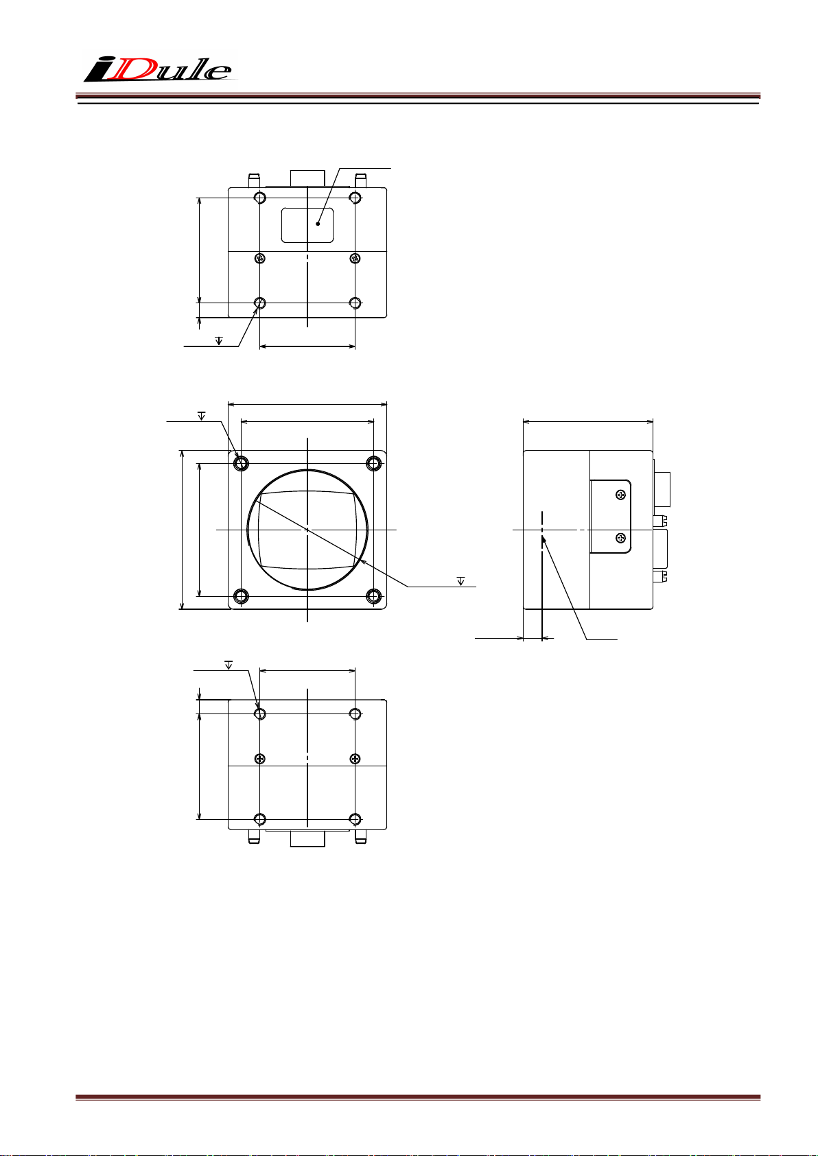
10. Dimensions
付貼板銘機
36.5
5
44M-4
4M-4
8
33
55
64
54
55
46
40.1x24M
65.6=BF
)riA nI(
44M-4
5
36.5
33
面像撮
Page 32
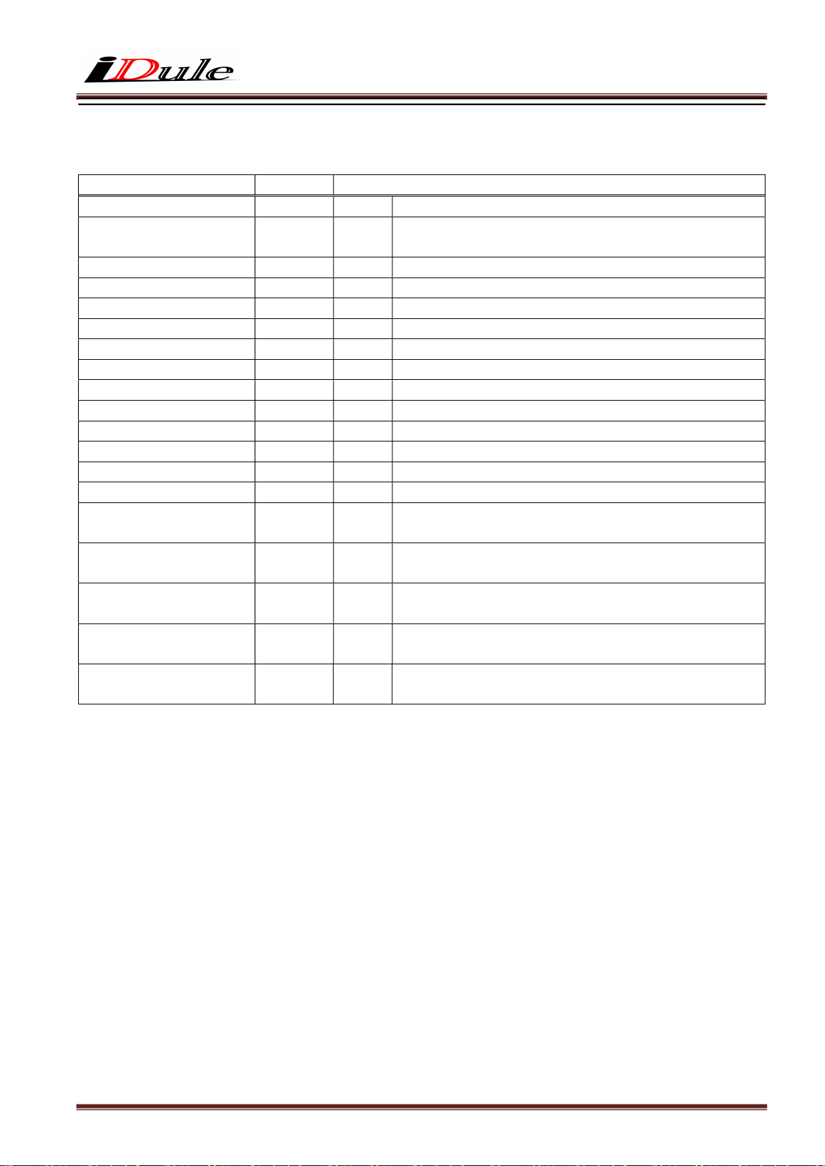
11. Initial Setting
Function Address Data
Preset shutter 01
Preset white balance
(color model)
02
Trigger shutter mode 04
Trigger polarity 05
Trigger input 06
Partial scan 08
Output mode 0A
Output bit 0B
Horizontal cutout 16
Trigger Hsync mode 17
Image flip 18
LED ON/OFF 1B
Manual gain 20-21
Manual shutter 24-25
Manual white balance R
(color model)
Manual white balance B
(color model)
Manual white balance G
(color model)
Partial scan
Start position
Partial scan
Effective line
28-29
2A-2B
2C-2D
40-41
50-51
00:
01:
00:
00:
00:
00:
00:
00:
00:
01:
00:
01:
0000:
0000:
0000:
0000:
0000:
0000:
1400:
OFF(1/9.4s)
3200K
Normal (Trigger OFF)
Positive
CC1
Full frame scan mode
8Tap Full Configuration
8bit
0
ON
Normal
ON
x1(0dB)
OFF(1/9.4s)
0dB
0dB
0dB
Start position 0
Effective line 7000
Page 33

12. Cases for Indemnity (Limited Warranty)
We shall be exempted from taking responsibility and held harmless for damage or losses incurred by
the user in the following cases.
In case damage or losses are caused by fire, earthquake, or other acts of God, acts by third party,
deliberate or accidental misuse by the user, or use under extreme operating conditions.
In case indirect, additional, consequential damages (loss of business interests, suspension of
business activities) are incurred as result of malfunction or non-function of the equipment, we
shall be exempted from responsibility for such damages.
In case damage or losses are caused by failure to observe the information contained in the
instructions in this product specification & operation manual.
In case damage or losses are caused by use contrary to the instructions in this product
specification & operation manual.
In case damage or losses are caused by malfunction or other problems resulting from use of
equipment or software that is not specified.
In case damage or losses are caused by repair or modification conducted by the customer or any
unauthorized third party (such as an unauthorized service representative).
13. CMOS Pixel Defect
IDULE compensates the noticeable CMOS pixel defects found at the shipping inspection prior to our
shipment. On very rare occasions, however, CMOS pixel defects might be noted with time of usage of
the products.
Cause of the CMOS pixel defects is the characteristic phenomenon of CMOS itself and IDULE is exempted
from taking any responsibilities for them. Should you have any questions on CMOS pixel defects
compensation, please contact us.
14. Product Support
When defects or malfunction of our products occur, and if you would like us to investigate on the cause
and repair, please contact your distributors you purchased from to consult and coordinate.
 Loading...