

Page 1
User Manual
For 37 in 1 Sensor Kit(ST1065)
www.openplatform.cc
Page 2
IDUINO for maker’s life
www.openplatform.cc 1
User Manual
for
37 in 1 Sensor Kit(ST1065)
Page 3

IDUINO for maker’s life
2 www.openplatform.cc
Module List
The order of modules is corresponding with the grid’s location, the last grid contains two
modules.
Name
Quantity
Picture
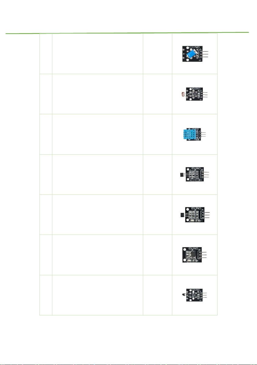
1
Joystick Module
1
2
Relay Module
1
3
Large Microphone Module
1
4
Small Microphone Module
1
5
Line Tracking Module
1
Page 4

IDUINO for maker’s life
www.openplatform.cc 3
6
Obstacle Avoidance Sensor
1
7
Flame Sensor Module
1
8
Linear Magnetic Hall Sensor
1
9
Touch Sensor
1
10
Digital Temperature Sensor
1
11
Buzzer Module
1
12
Passive Buzzer/Sounder
1
Page 5
IDUINO for maker’s life
4 www.openplatform.cc
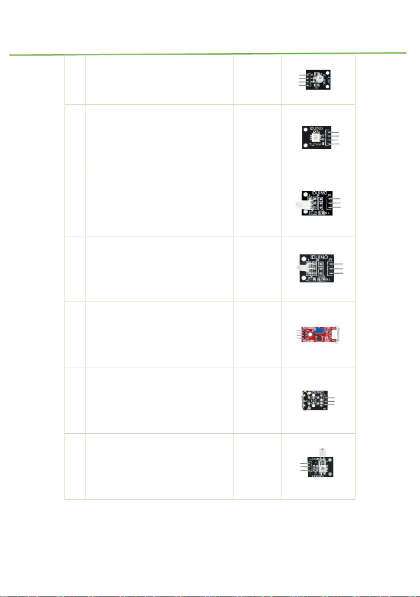
13
RGB LED Module
1
14
SMD RGB LED Module
1
15
Two Color LED Module(5mm)
1
16
Two Color LED Module(3mm)
1
17
Reed Switch Module
1
18
Mini Reed Switch Module
1
19
Heartbeat Sensor
1
Page 6
IDUINO for maker’s life
www.openplatform.cc 5
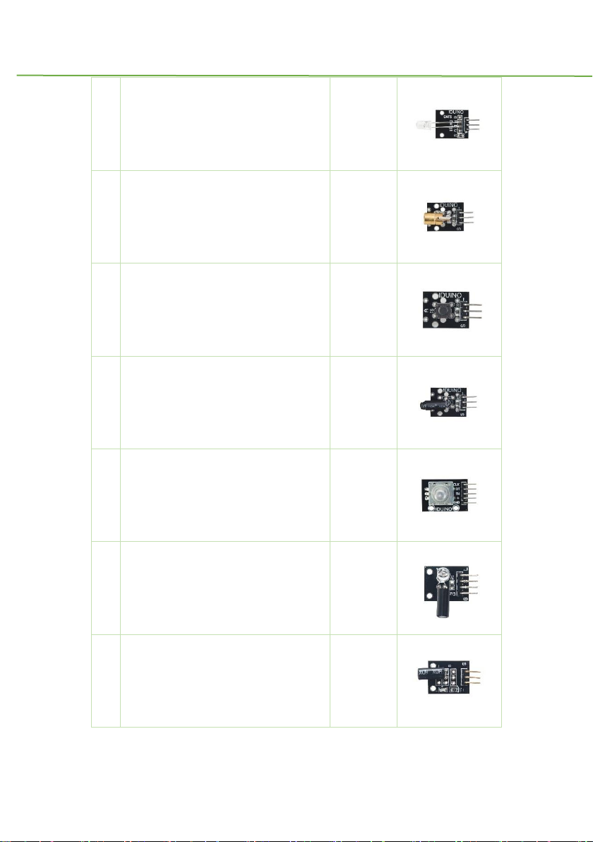
20
Seven Color Flashing
1
21
Laser Module
1
22
Tactile Switch Module
1
23
Shock Module
1
24
Rotary Encode Module
1
25
Switch Light Module
2
26
Tilt Switch Module
1
Page 7
IDUINO for maker’s life
6 www.openplatform.cc
27
Ball Switch Module
1
28
Light Dependent Resistor Module
1
29
Temperature and Humidity Module
1
30
Analog Hall Effect Sensor
1
31
Class Hall Magnetic Sensor
1
32
Digital Temperature Module
1
33
Analog Temperature Sensor
1
Page 8
IDUINO for maker’s life
www.openplatform.cc 7
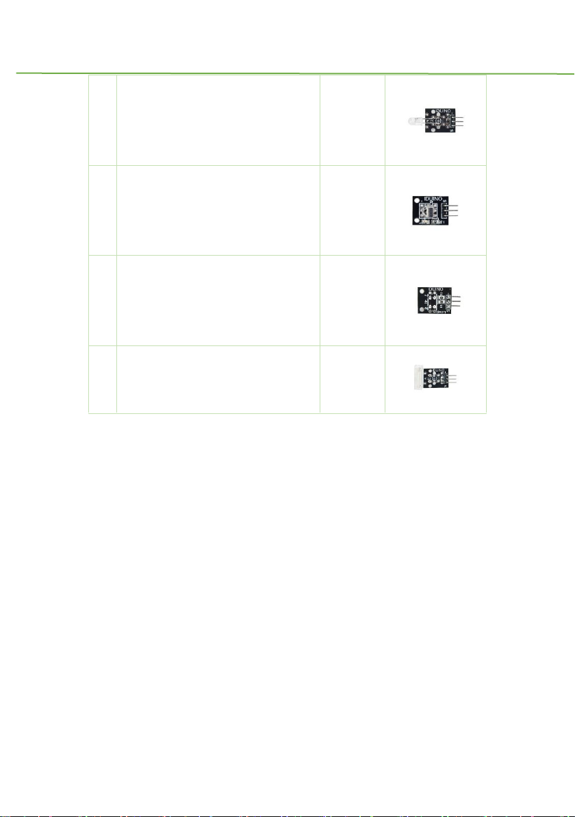
34
IR Transmitter Module
1
35
IR Receiver Module
1
36
Optical Broken Module
1
37
Hit Sensor Module
1
Page 9
IDUINO for maker’s life
8 www.openplatform.cc
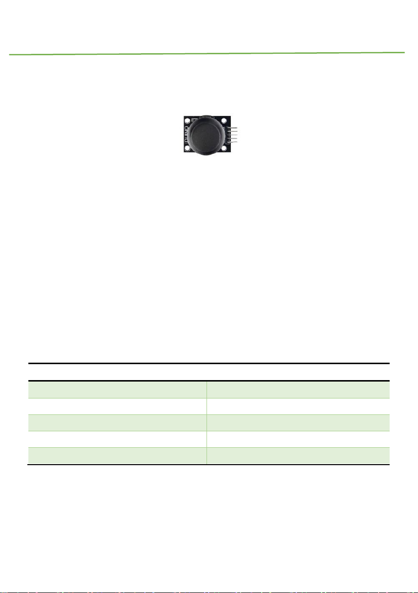
Module 1: Joystick module
1.Introduction
This joystick module maybe the best choice for your controller of DIY project. It has two
analog input pins to control X, Y axis and also has button input, someone may call it Z axis,
but it only input digital signal with 0 or 1.
Specifications:
Two analog pin(X, Y axis), one digital pin(button).
Input voltage: 5V
Output voltage: 2.5V
Size: 37*25*32mm
Weight: 8g
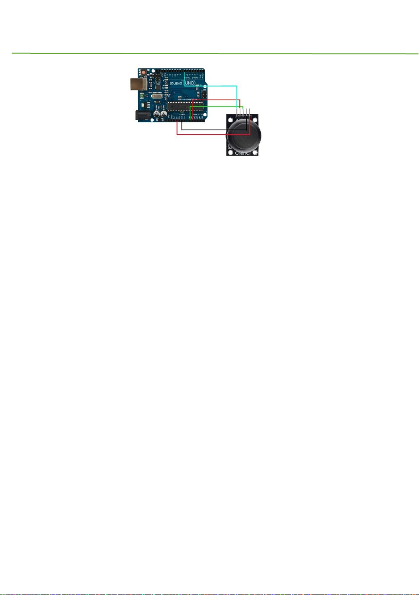
2.PinOut
Pin
Description
GND
Ground
+5v
Power
VRX
X axis analog signal input
VRY
Y axis analog signal input
SW
Button key, value is 0 or 1
3.Example
Here is an example, connect the circuit as below and run the code, you will see the analog
value from X, Y axis and button through the Serial Monitor.
Page 10
IDUINO for maker’s life
www.openplatform.cc 9
*********Code begin*********
int sensorPin = 5;
int value = 0;
void setup() {
pinMode(3, OUTPUT);
Serial.begin(9600);
}
void loop() {
value = analogRead(0);
Serial.print("X:");
Serial.print(value, DEC);
value = analogRead(1);
Serial.print(" | Y:");
Serial.print(value, DEC);
value = digitalRead(7);
Serial.print(" | Z: ");
Serial.println(value, DEC);
delay(100);
}
*********Code End*********
Page 11

IDUINO for maker’s life
10 www.openplatform.cc
Module 2: Relay Module
1. Introduction
The module is uses SRD relay module to control high-voltage electrical device. It can be
used in interactive projects and can also be used to control the lighting, electrical and other
equipment. It can be controlled directly by a wide range of microcontrollers and can be
controlled through the digital IO port, such as solenoid valves, lamps, motors and other high
current or high voltage devices.
Remarks: This is declare that the relay module is only for low voltage (below 75 V/DC and
50 V/AC).
specifications:
Number of I/O Channels: 1
Input Voltage: 5V DC
Type: Digital
Control signal: TTL level
Max allowable output Voltage: 50V AC/75V DC
Indication LED for Relay's Status
2. Pinout
Pin Name
Description
“+”
Power(5V DC)
“-”
GND
“S”
Signal pin, connected with Arduino
“NO”
Normally open terminal
“NC”
Normally closed terminal
“C”(middle pin)
Common terminal, Which connected with the power for the load.
Page 12
IDUINO for maker’s life
www.openplatform.cc 11
3. Example
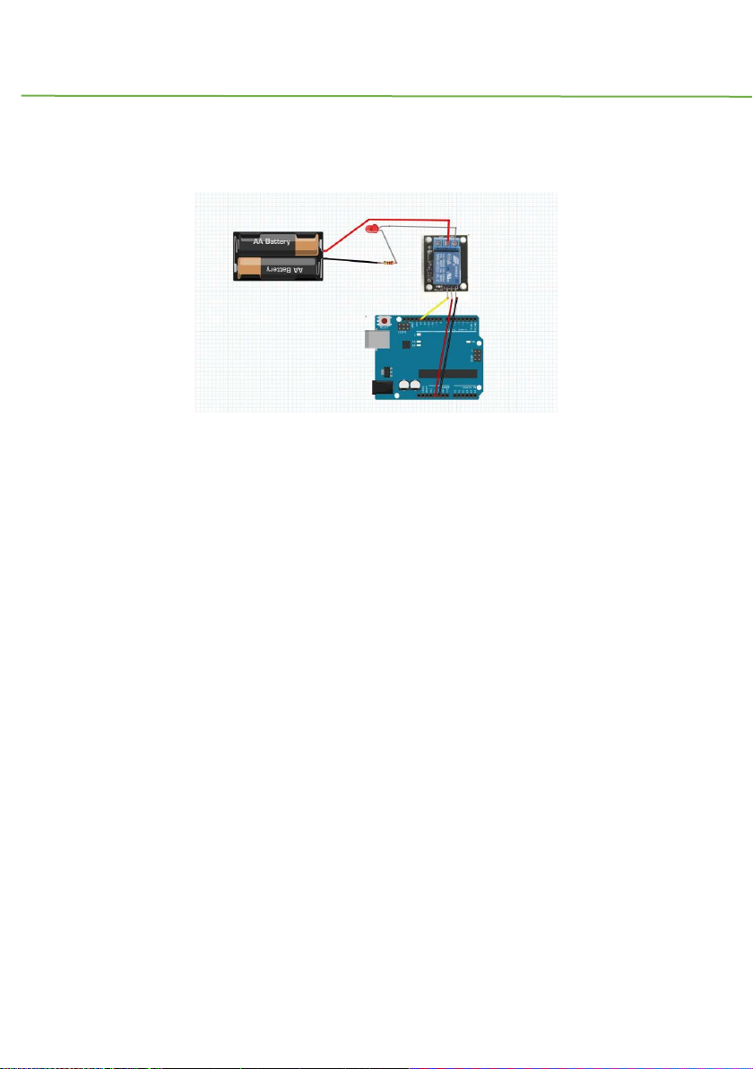
This example controls a LED(or other high power load) via the Relay module.
Physical connection as below:
The example code as below:
*********Code begin*********
int led = 13;
// the setup routine runs once when you press reset:
void setup() {
// initialize the digital pin as an output.
pinMode(led, OUTPUT);
}
// the loop routine runs over and over again forever:
void loop() {
digitalWrite(led, HIGH); // turn the LED on (HIGH is the voltage level)
delay(1000); // wait for a second
digitalWrite(led, LOW); // turn the LED off by making the voltage LOW
delay(1000); // wait for a second
}
*********Code End*********
Page 13

IDUINO for maker’s life
12 www.openplatform.cc
Module3. Large Microphone Module
1. Introduction
It’s a high sensitivity sound detection module, which has two output signal pin. one digital
pin(D0), When it detect some sound up to certain threshold, it can output High or Low level.
One analog pin(A0), it can real-time output voltage signal of the microphone.
Specification
Voltage:5V/3.3V
Electret microphone(It’s different from module4)
there is a mounting screw hole 3mm
the use 5v DC power supply
with analog output
there is threshold level output flip
high sensitive microphone and high sensitivity.
a power indicator light
the comparator output is light
Weight: 4g
Frequency Response range:50Hz~20kHz
Impedance:2.2K ohm
Sensitivity:48~66dB
polar pattern:Universal
Operating temperature: -40 to 85 degrees Celsius
Operating humidity: <90%
Page 14
IDUINO for maker’s life
www.openplatform.cc 13
Storage temperature : -40 to 85degrees Celsius
Storage humidity : <75%
product size: 45*15mm
2. Pinout
Pin
Description
A0
Analog signal output pin
G
Ground
+
Power(5V/3.3V)
D0
Digital signal output pin
3. Example
We will use three example to show the different function of this module.
Example 1 show you how to use the digital pin(D0), Example 2 show you how to use the
digital pin(A0), In Example 3, we can try to combine this two function into one experiment.
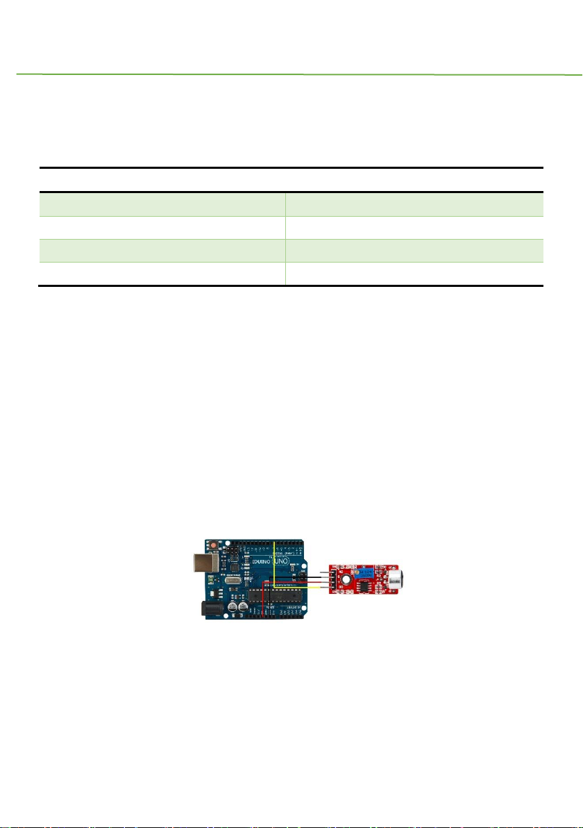
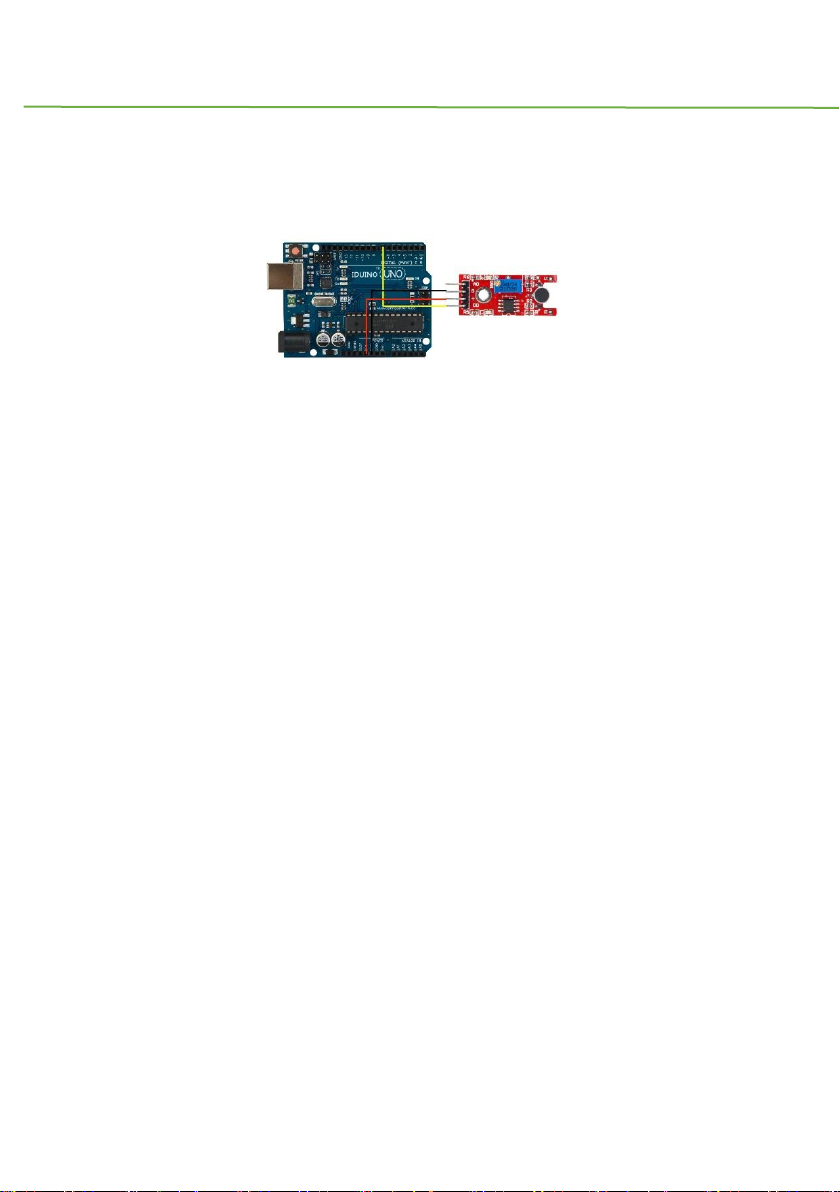
3.1 Example 1
This example shows you the digital pin function, connect Pin12(Arduino) to a LED light,
and connect this module as below, and upload the code.
Then turn the variable resistor until the LED12 turns off. Now you can handclap or make
a sound, you will see the LED12 turns on.
Code for Example1
********Code begin********
Page 15

IDUINO for maker’s life
14 www.openplatform.cc
int Led = 12 ;// define LED Interface
int buttonpin = 7; // define D0 Sensor Interface
int val = 0;// define numeric variables val
void setup ()
{
pinMode (Led, OUTPUT) ;// define LED as output interface
pinMode (buttonpin, INPUT) ;// output interface D0 is defined sensor
}
void loop ()
{
val = digitalRead(buttonpin);//
if (val == HIGH) //
{
digitalWrite (Led, HIGH);
}
else
{
digitalWrite (Led, LOW);
}
}
********Code End********
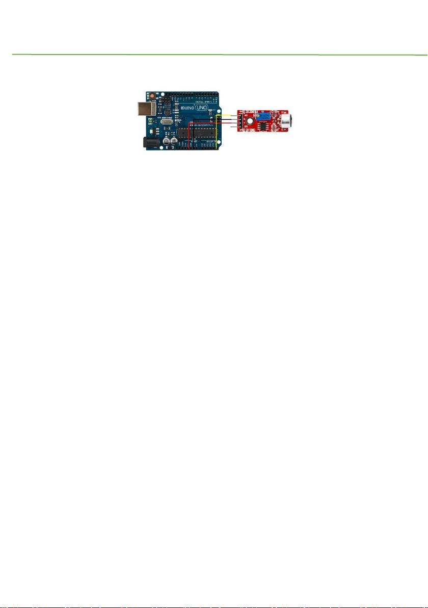
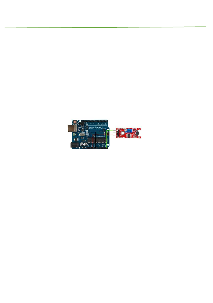
3.2 Example 2
This example shows you the Analog pin function, connect this module as below picture,
and upload the code.
Then open the Serial monitor, you can see some number between 0 to 1023. And now if
you make some high or low voice, the number is changing.
Page 16
IDUINO for maker’s life
www.openplatform.cc 15
Code for Example2
********Code begin********
int sensorPin = A5; // select the input pin for the potentiometer
void setup ()
{
Serial.begin (9600);
}
void loop ()
{
sensorValue = analogRead (sensorPin);
delay (500);
Serial.println (sensorValue, DEC);
}
********Code End********
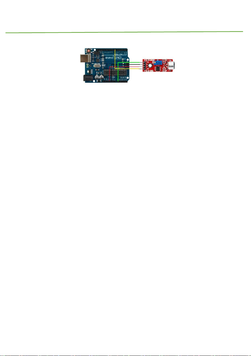
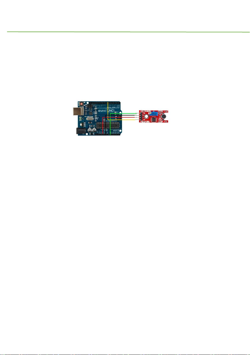
3.3 Example 3
In this example we try to combine digital pin and analog pin together to control two LED
lights, connection and code as below.
Page 17
IDUINO for maker’s life
16 www.openplatform.cc
Code for example 3
********Code begin********
int Led=13;
int ledPin=12;
int buttonpin=7;
int sensorPin = A0;
int sensorValue = 0;
int val;
void setup()
{
Serial.begin(9600);
pinMode(Led,OUTPUT);
pinMode(ledPin, OUTPUT);
pinMode(buttonpin,INPUT);
}
void loop()
{
sensorValue = analogRead(sensorPin);
digitalWrite(ledPin, HIGH);
delay(sensorValue);
digitalWrite(ledPin, LOW);
Page 18

IDUINO for maker’s life
www.openplatform.cc 17
delay(sensorValue);
Serial.println(sensorValue, DEC);
val=digitalRead(buttonpin);
if(val==HIGH)
{
digitalWrite(Led,HIGH);
}
else
{
digitalWrite(Led,LOW);
}
}
********Code End********
Module 4: Small microphone module
1.Introduction
This module is similar with the large microphone module(ST1146). The only difference is
the microphone, not only the size, but also the function. The large microphone module has
an electronic microphone, and the small microphone module just has a normal microphone.
The electret microphone has more high sensitivity, but they share the same work method.
Specification
Voltage:5V/3.3V
there is a mounting screw hole 3mm
Page 19

IDUINO for maker’s life
18 www.openplatform.cc
the use 5v DC power supply
with analog output
there is threshold level output flip
high sensitive microphone and high sensitivity.
a power indicator light
the comparator output is light
Weight: 4g
Frequency Response range:50Hz~20kHz
Impedance:2.2K ohm
Sensitivity:48~66dB
polar pattern:Universal
Operating temperature: -40 to 85 degrees celsius
Operating humidity: <90%
Storage temperature : -40 to 85 degrees celsius
Storage humidity : <75%
product size: 45*15mm
2. Pinout
Pin
Description
A0
Analog signal output pin
G
Ground
+
Power(5V/3.3V)
D0
Digital signal output pin
3. Example
We will use three example to show the different function of this module.
Example 1 show you how to use the digital pin(D0), Example 2 show you how to use the
digital pin(A0), In Example 3, we can try to combine this two function into one experiment.
3.1 Example 1
This example shows you the digital pin function, connect Pin12(Arduino) to a LED light,
and connect this module as below, and upload the code.
Page 20
IDUINO for maker’s life
www.openplatform.cc 19
Then turn the variable resistor until the LED12 turns off. Now you can handclap or make
a sound, you will see the LED12 turns on.
Code for Example1
********Code begin********
int Led = 12 ;// define LED Interface
int buttonpin = 7; // define D0 Sensor Interface
int val = 0;// define numeric variables val
void setup ()
{
pinMode (Led, OUTPUT) ;// define LED as output interface
pinMode (buttonpin, INPUT) ;// output interface D0 is defined sensor
}
void loop ()
{
val = digitalRead(buttonpin);//
if (val == HIGH) //
{
digitalWrite (Led, HIGH);
}
else
{
Page 21
IDUINO for maker’s life
20 www.openplatform.cc
digitalWrite (Led, LOW);
}
}
********Code End********
3.2 Example 2
This example show you the Analog pin function, connect this module as below picture, and
upload the code.
Then open the Serial monitor, you can see some number between 0 to 1023. And now if
you make some high or low voice, the number is changing.
Code for Example2
********Code begin********
int sensorPin = A5; // select the input pin for the potentiometer
void setup ()
{
Serial.begin (9600);
}
void loop ()
{
sensorValue = analogRead (sensorPin);
delay (500);
Serial.println (sensorValue, DEC);
Page 22
IDUINO for maker’s life
www.openplatform.cc 21
}
********Code End********
3.3 Example 3
In this example we try to combine digital pin and analog pin together to control two LED
lights, connection and code as below.
Code for example 3
********Code begin********
int Led=13;
int ledPin=12;
int buttonpin=7;
int sensorPin = A0;
int sensorValue = 0;
int val;
void setup()
{
Serial.begin(9600);
pinMode(Led,OUTPUT);
pinMode(ledPin, OUTPUT);
pinMode(buttonpin,INPUT);
}
void loop()
Page 23

IDUINO for maker’s life
22 www.openplatform.cc
{
sensorValue = analogRead(sensorPin);
digitalWrite(ledPin, HIGH);
delay(sensorValue);
digitalWrite(ledPin, LOW);
delay(sensorValue);
Serial.println(sensorValue, DEC);
val=digitalRead(buttonpin);
if(val==HIGH)
{
digitalWrite(Led,HIGH);
}
else
{
digitalWrite(Led,LOW);
}
}
********Code End********
Module5: Line tracking module
1.Introduction
With this module your DIY car or robot can walk only along one line way. When the detector
move from white to black, it could output TTL signal, So if you draw one black line between
Page 24
IDUINO for maker’s life
www.openplatform.cc 23
in the two wheels of your car, it will walk along your expecting road.
Specification:
Voltage: 3.3V to 5V
Operating current: 20mA @ 5V
Operating temperature range: 0°C ~ + 50°C
Black for LOW output, White for HIGH output
Size:45x10mm
2 Pinout
Pin
Description
S
Digital output pin, black is Low, white is
High
V+
Power(5V DC)
G
Ground
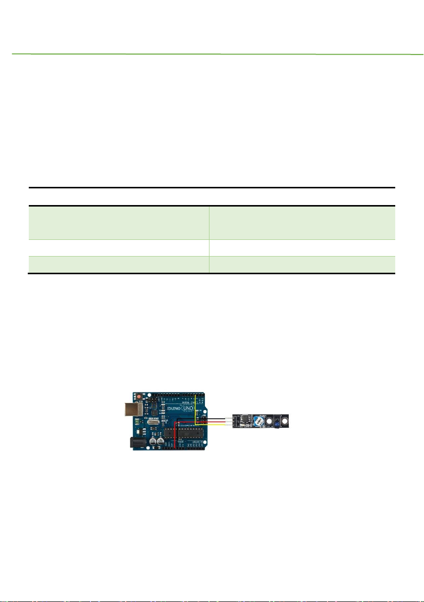
3. Example
The example show that when the sensor detect black area, the “s” pin output Low TTL
signal, then the LED13 turn off meanwhile the light ”L” on this module turns on. On the
contrary, LED13 turns on.
The connection as below:
********Code begin********
int Led=13;
int buttonpin=3;
Page 25
IDUINO for maker’s life
24 www.openplatform.cc
int val;
void setup()
{ pinMode(Led,OUTPUT);
pinMode(buttonpin,INPUT);
}
void loop()
{
val=digitalRead(buttonpin);
if(val==HIGH)
{ digitalWrite(Led,HIGH); }
else { digitalWrite(Led,LOW); }
}
********Code End********
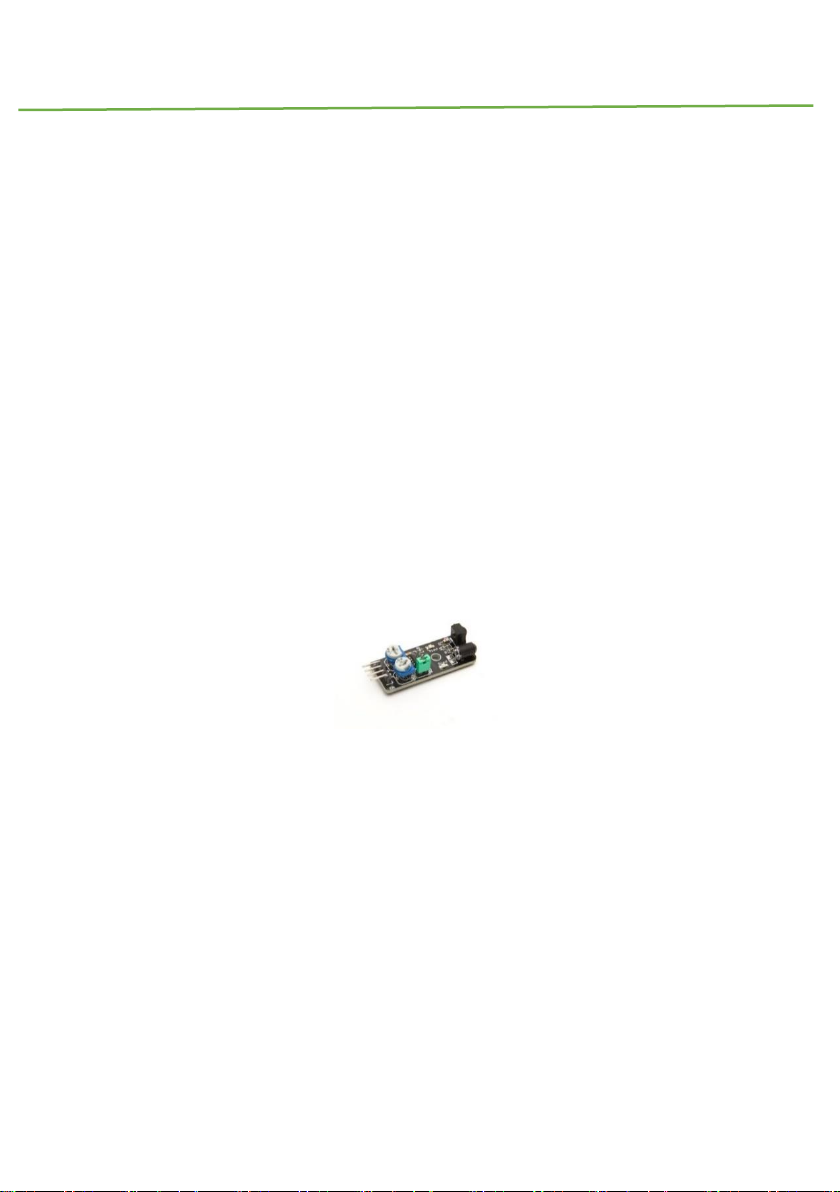
Module 6: Obstacle Avoidance Sensor
1. Introduction
Infrared obstacle avoidance sensor is designed for the design of a wheeled robot
obstacle avoidance sensor distance adjustable. This ambient light sensor adaptable, high
precision, having a pair of infrared transmitter and receiver, transmitter tubes emit a certain
frequency of infrared, When detecting the direction of an obstacle (reflector), the infrared
receiver tube receiver is reflected back, when the indicator is lit, Through the circuit, the
signal output interface output digital signal that can be detected by means of potentiometer
knob to adjust the distance, the effective distance From 2 ~ 40cm, working voltage of 3.3V-
5V, operating voltage range as broad, relatively large fluctuations in the power supply voltage
of the situation Stable condition and still work for a variety of microcontrollers, Arduino
Page 26

IDUINO for maker’s life
www.openplatform.cc 25
controller, BS2 controller, attached to the robot that
Can sense changes in their surroundings.
Specification:
Working voltage: DC 3.3V-5V
Working current: ≥ 20mA
Operating temperature: -10 ℃ - +50 ℃
detection distance :2-40cm
IO Interface: 4-wire interfaces (- / + / S / EN)
Output signal: TTL level (low level there is an obstacle, no obstacle high)
Adjustment: adjust multi-turn resistance
Effective angle: 35 °
Size: 45mm × 23mm
2. Pinout
Pin
Description
“+”
Power(3.3V~5V DC)
Gnd
ground
out
Signal pin
EN
Enable pin that Low level works, usually
useless
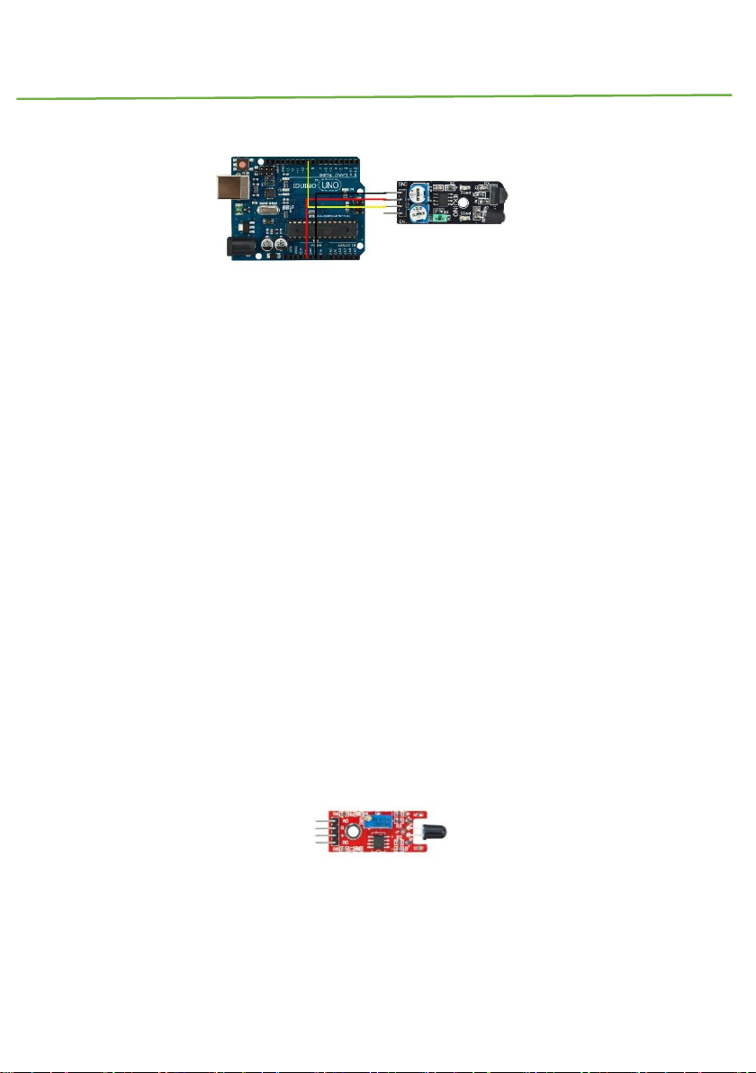
3.Example code
Here is a small example to test the sensor. By default, the sensor returns 1 on the Serial
Monitor. When detecting something, the sensor return 0.
The connection as below:
Page 27
IDUINO for maker’s life
26 www.openplatform.cc
******Code begin******
int count;
void setup() {
Serial.begin (9600);
pinMode (9, INPUT); //Sensor output
}
void loop() {
Serial.print ("Sensor: ");
Serial.println (digitalRead(9)); //print the sensor output
delay (500); //wait half a second
}
******Code End******
Module 7: Flame Sensor Module
1.Introduction
Page 28

IDUINO for maker’s life
www.openplatform.cc 27
This is a flame sensor module that can be used to detected whether a flame source exist
or not. It’s sensitive to IR wavelength at 760nm~1100nm. Usually, the detection angle is
about 60 degrees.
Specification
Operation voltage: 5V for analog, 3.3V for digital
Both digital and analog output pin
Adjustable sensitive
Detect IR wavelength: 760nm~1100nm
Size: 45*15mm
Weight: 3g
2.Pinout
Pin
Description
A0
Analog output pin, real-time output voltage
signal on thermal resistance
D0
Digital output pin, output Low or High
signal when the temperature reaches a
certain threshold
+
Power(5V for analog, 3.3V for digital)
G
Ground
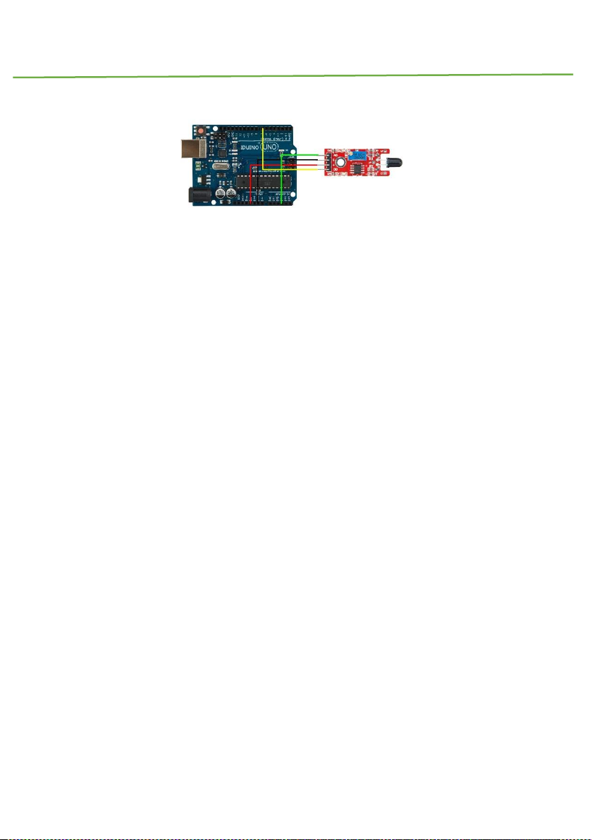
3.Example
Here is an example for how to use both the analog pin(A0) and digital pin(D0), connect the
circuit as below, upload this sketch, open the Serial Monitor, you will see the real-time value
of the thermal resistance, and once the flame closing to it, the value will change. If the value
reaches a certain threshold, the D0 pin will output High signal meanwhile the LED13 turns
on. And threshold can be adjusted by potentiometer.
Page 29
IDUINO for maker’s life
28 www.openplatform.cc
********Code begin********
int Led = 13 ;// define LED Interface
int buttonpin = 3; // define the flame sensor interface
int analoog = A3; // define the flame sensor interface
int val ;// define numeric variables val
float sensor; //read analoog value
void setup ()
{
pinMode (Led, OUTPUT) ;// define LED as output interface
pinMode (buttonpin, INPUT) ;// output interface defines the flame sensor
pinMode (analoog, INPUT) ;// output interface defines the flame sensor
Serial.begin(9600);
}
void loop ()
{
sensor = analogRead(analoog);
Serial.println(sensor); // display tempature
val = digitalRead (buttonpin) ;// digital interface will be assigned a
value of 3 to read val
if (val == HIGH) // When the flame sensor detects a signal, LED flashes
{
Page 30
IDUINO for maker’s life
www.openplatform.cc 29
digitalWrite (Led, HIGH);
}
else
{
digitalWrite (Led, LOW);
}
delay(1000);
}
********Code End********
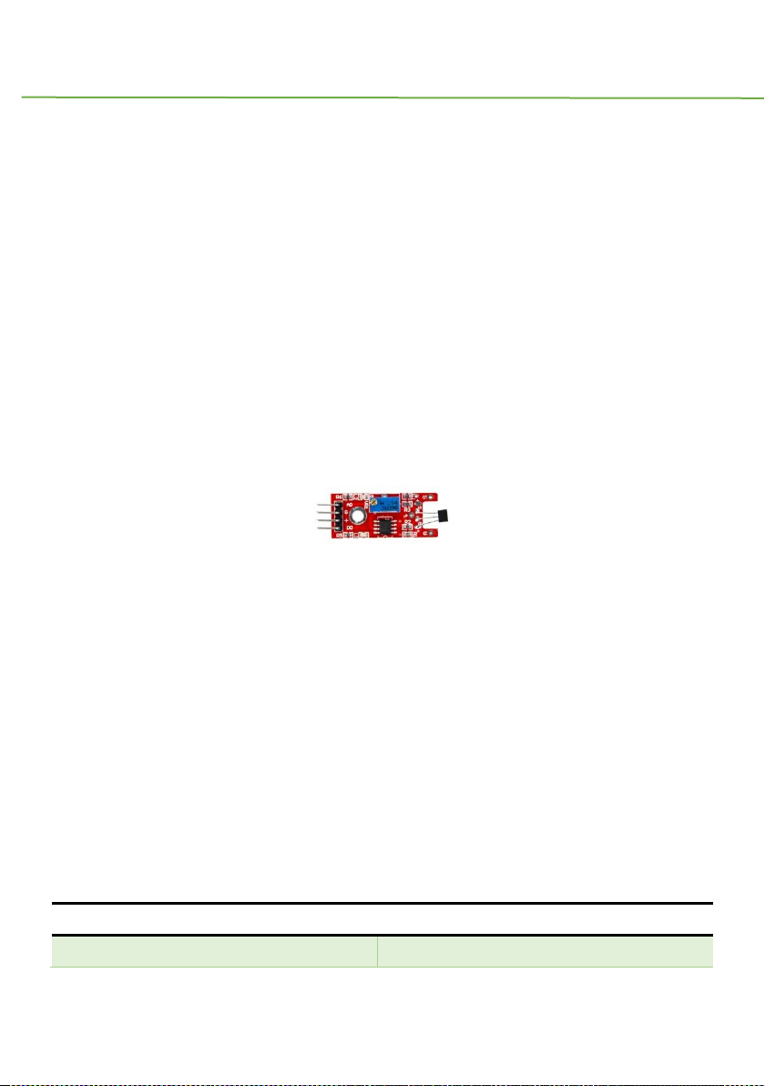
Module 8:Linear Magnetic Hall Sensor (SE014)
1 Introduction
This module is analog hall sensor module, it can both output an analog and digital voltage
at the signal pin of this module. This module is different from hall magnetic sensor(Module
31), which just output digital signal, like a magnetic switch.
Specification
Operation voltage: 5V
4Pin
Size:45*12mm
Weight: 3g
2 Pinout
Pin
Description
A0
Analog output pin, real-time output voltage
Page 31

IDUINO for maker’s life
30 www.openplatform.cc
signal
G
Ground
+
Power
D0
Digital signal pin
3.Example
In this example, If no magnetic field is present, the signal line of the sensor is HIGH (3.5
V). If a magnetic field is presented to the sensor, the signal line goes LOW, at the same time
the LED on the sensor lights up.
The connection as below:
Example Code:
******Code begin******
int Led = 13 ; // define LED Interface
int SENSOR = 10 ; // define the Hall magnetic sensor interface
int val ; // define numeric variables val
void setup ()
{
pinMode (Led, OUTPUT) ; // define LED as output interface
pinMode (SENSOR, INPUT) ; // define the Hall magnetic sensor line as
input
}
void loop ()
Page 32

IDUINO for maker’s life
www.openplatform.cc 31
{
val = digitalRead (SENSOR) ; // read sensor line
if (val == LOW) // when the Hall sensor detects a magnetic field, Arduino
LED lights up
{
digitalWrite (Led, HIGH);
}
{
digitalWrite (Led, LOW);
}
}
******Code End******
Module 9:Touch Sensor
1 Introduction
This module is a metal touch sensor, it looks like module7(flame sensor module), has 4
pin, including one analog pin and digital pin, but usually we just use the digital pin. Which
can be used to detect whether a human body is touching the metal detector.
Specification
Operation voltage: 5V
Both digital and analog output pin
Adjustable sensitive
Size: 45*15mm
Page 33

IDUINO for maker’s life
32 www.openplatform.cc
Weight: 3g
2 Pinout
Pin
Description
A0
Analog output pin, real-time output voltage
signal(usually useless)
D0
Digital output pin, output Low or High signal
when the human body touch it
+
Power(5V for analog, 3.3V for digital)
G
Ground
1.Example
Here is an example show you how to use this module, connection as below. When you touch
the metal detector via your finger, the LED13 turns on.
********Code begin********
int Led = 13;// define LED Interface
int buttonpin = 3;
int val;// define numeric variables val
void setup ()
{
pinMode (Led, OUTPUT) ;//define LED as output interface
pinMode (buttonpin, INPUT) ;// define metal touch sensor output interface
}
Page 34

IDUINO for maker’s life
www.openplatform.cc 33
void loop ()
{
val = digitalRead (buttonpin) ;//digital interface will be assigned a value
of 3 to read val
if (val == HIGH) //When the metal touch sensor detects a signal, LED flashes
{
digitalWrite (Led, HIGH);
}
else
{
digitalWrite (Led, LOW);
}
}
********Code End********
Module10: Digital Temperature Sensor(SE017)
1.Introduction
This module has both analog signal output pin and digital signal output pin, which is
different from analog temperature sensor(module33) and other temperature sensor
module.
A thermistor is a type of resistor whose resistance is dependent on temperature, more
so than in standard resistors. The word is a portmanteau of thermal and resistor.
Thermistors are widely used as inrush current limiter, temperature sensors (NTC type
Page 35

IDUINO for maker’s life
34 www.openplatform.cc
typically), self-resetting overcurrent protectors, and self-regulating heating elements.
The Module’s feature as below:
Feature
Value
Model No.
NTC-MF52 3950
Temperature Range
-55℃~+125℃
Accuracy
+/- 0.5℃
2.Pinout
Pin
Description
A0
Analog signal output pin
D0
Digital signal output pin
G
Gnd
“+”
Vcc(reference voltage:5V DC)
Temperature convert Formula
Here we use Steinhart–Hart equation to calculate the corresponding temperature. The
equation is
where:
T is the temperature (in Kelvins)
R is the resistance at T (in ohms)
A, B, and C are the Steinhart–Hart coefficients which vary depending on the type
and model of thermistor and the temperature range of interest. (The most general form
of the applied equation contains a [ln(R)]^2 term, but this is frequently neglected
because it is typically much smaller than the other coefficients).
Note: For this module, the recommended coefficients of A,B,C are
A equals 0.001129148;
B equals 0.000234125;
C equals 0.0000000876741;
Page 36

IDUINO for maker’s life
www.openplatform.cc 35
More, the same item products has a little bit different A,B,C coefficients , which depends
your environmental temperature. If the recommended coefficients are not accurate
enough, you’d better amend the A,B,C coefficients by Thermistor Calculator tool.
3 Example
This is a simple code for the NTC thermistor module, Connection as below:
Example code :
******Code begin******
#include <math.h>
double Thermister(int RawADC) {
double Temp;
Temp = log(((10240000/RawADC) - 10000));
Temp = 1 / (0.001129148 + (0.000234125 + (0.0000000876741 * Temp * Temp ))*
Temp );
Temp = Temp - 273.15;
return Temp;
}
void setup() {
Serial.begin(9600);
}
void loop()
{ Serial.print(Thermister(analogRead(0)));
Page 37

IDUINO for maker’s life
36 www.openplatform.cc
Serial.println("c");
delay(1000); }
******Code End******
Module 11: Buzzer module
1.Introduction
It’s a basic sound component. Comparing with the passive buzzer, it can be driven by both
DC signal and square wave signal.
Specification
Operation voltage: 3.3V/5V
Size: 25*15*12mm
Weight: 2g
2 pinout
Pin
Description
S
Signal input pin, which can be driven by DC
signal and square wave signal
+
Power(3.3V/5V), you may not see this mark
on the board, it’s the middle pin
-
Ground
3 Example
Here is a example that driven the active buzzer sound. The connection as below:
Page 38

IDUINO for maker’s life
www.openplatform.cc 37
********Code begin********
int speakerPin = 8;
void setup () {
pinMode (speakerPin, OUTPUT);
}
void loop () {
analogWrite (speakerPin, 255);
delay (50);
analogWrite (speakerPin, 0);
delay (10);
}
********Code End********
Module 12: Passive Buzzer
1 Introduction
Page 39

IDUINO for maker’s life
38 www.openplatform.cc
This module is similar with the Active Buzzer(Module 11), the only difference is that this
module only can be driven square wave signal, not DC signal.
2 pinout
Pin
Description
S
Signal input pin, which can be driven by
square wave signal
+
Power(3.3V/5V), you may not see this mark
on the board, it’s the middle pin
-
Ground
3 Example
Here is a example that driven the Passive buzzer sound. The connection as below:
********Code begin********
int buzzer = 8 ;// setting controls the digital IO foot buzzer
void setup ()
{
pinMode (buzzer, OUTPUT) ;// set the digital IO pin mode, OUTPUT out of
Wen
}
void loop ()
{
unsigned char i, j ;// define variables
Page 40

IDUINO for maker’s life
www.openplatform.cc 39
while (1)
{
for (i = 0; i <80; i++) // Wen a frequency sound
{
digitalWrite (buzzer, HIGH) ;// send voice
delay (1) ;// Delay 1ms
digitalWrite (buzzer, LOW) ;// do not send voice
delay (1) ;// delay ms
}
for (i = 0; i <100; i++) // Wen Qie out another frequency sound
{
digitalWrite (buzzer, HIGH) ;// send voice
delay (2) ;// delay 2ms
digitalWrite (buzzer, LOW) ;// do not send voice
delay (2) ;// delay 2ms
}
}
}
********Code End********
Module13 : RGB LED Module
1. Introduction
RGB LED module consists of a full-color LED made by R, G, B three pin PWM voltage input
Page 41

IDUINO for maker’s life
40 www.openplatform.cc
can be adjusted. Primary colors (red / blue / green) strength in order to achieve full color
mixing effect. Control of the module with the Arduino can be achieved Cool lighting effects.
And three resistor has been soldered on this board, so needn’t worry to burn out the LED
light under the long time work.
Specification
Red Vf: 1.8 to 2.1V
Green Vf: 3.0 to 3.2V
Blue Vf: 3.0 to 3.2V
Red color: 620-625 nm
Green color: 520-525 nm
Blue color: 465-470 nm
Red brightness @ ~20mA: 600-800 mcd
Blue brightness @ ~20mA: 800-1000 mcd
Green brightness @ ~20mA: 1500-2000mcd
2. Pinout
Pin Name
Description
“R”
Red light
“G”
Green light
“B”
Blue light
“-”
Ground
3. Example
In this example, we blink an LED and using an RGB LED we can generate any color we
want.
Here is the physical connection:
Page 42

IDUINO for maker’s life
www.openplatform.cc 41
********Code begin********
//RGB LED pins
int ledDigitalOne[] = {10, 11, 9}; //the three digital pins of the digital
LED
//10 = redPin, 11 = greenPin, 9 = bluePin
const boolean ON = HIGH; //Define on as LOW (this is because we use a
//common
//Anode RGB LED (common pin is connected to +5
//volts)
const boolean OFF = LOW; //Define off as HIGH
//Predefined Colors
const boolean RED[] = {ON, OFF, OFF};
const boolean GREEN[] = {OFF, ON, OFF};
const boolean BLUE[] = {OFF, OFF, ON};
const boolean YELLOW[] = {ON, ON, OFF};
const boolean CYAN[] = {OFF, ON, ON};
const boolean MAGENTA[] = {ON, OFF, ON};
const boolean WHITE[] = {ON, ON, ON};
const boolean BLACK[] = {OFF, OFF, OFF};
//An Array that stores the predefined colors (allows us to later randomly
display a color)
Page 43

IDUINO for maker’s life
42 www.openplatform.cc
const boolean* COLORS[] = {RED, GREEN, BLUE, YELLOW, CYAN, MAGENTA, WHITE,
BLACK};
void setup(){
for(int i = 0; i < 3; i++){
pinMode(ledDigitalOne[i], OUTPUT); //Set the three LED pins as outputs
}
}
void loop(){
/* Example - 1 Set a color
Set the three LEDs to any predefined color
*/
setColor(ledDigitalOne, YELLOW); //Set the color of LED one
/* Example - 2 Go through Random Colors
Set the LEDs to a random color
*/
//randomColor();
}
void randomColor(){
int rand = random(0, sizeof(COLORS) / 2); //get a random number within
the range of colors
setColor(ledDigitalOne, COLORS[rand]); //Set the color of led one to a
random color
delay(1000);
}
/* Sets an led to any color
led - a three element array defining the three color pins (led[0] =
redPin, led[1] = greenPin, led[2] = bluePin)
color - a three element boolean array (color[0] = red value (LOW = on,
Page 44

IDUINO for maker’s life
www.openplatform.cc 43
HIGH = off), color[1] = green value, color[2] =blue value)
*/
void setColor(int* led, boolean* color){
for(int i = 0; i < 3; i++){
digitalWrite(led[i], color[i]);
}
}
void setColor(int* led, const boolean* color){
boolean tempColor[] = {color[0], color[1], color[2]};
setColor(led, tempColor);
}
********Code End********
Module14 : SMD RGB LED Module
1. Introduction
RGB LED module consists of a full-color LED made by R, G, B three pin PWM voltage input
can be adjusted. Primary colors (red / blue / green) strength in order to achieve full color
mixing effect. Control of the module with the Arduino can be achieved Cool lighting effects.
Specification
Red Vf: 1.8 to 2.1V
Green Vf: 3.0 to 3.2V
Blue Vf: 3.0 to 3.2V
Red color: 620-625 nm
Green color: 520-525 nm
Blue color: 465-470 nm
Page 45

IDUINO for maker’s life
44 www.openplatform.cc
Red brightness @ ~20mA: 600-800 mcd
Blue brightness @ ~20mA: 800-1000 mcd
Green brightness @ ~20mA: 1500-2000mcd
2. Pinout
Pin Name
Description
“R”
Red light
“G”
Green light
“B”
Blue light
“-”
Ground
3. Example
In this example, we blink an LED and using an RGB LED we can generate any color we
want.
Here is the physical connection:
********Code begin********
int ledDigitalOne[] = {10, 11, 9}; //the three digital pins of the digital
LED
//10 = redPin, 11 = greenPin, 9 = bluePin
const boolean ON = HIGH; //Define on as LOW (this is because we use a
//common
//Anode RGB LED (common pin is connected to +5
//volts)
Page 46

IDUINO for maker’s life
www.openplatform.cc 45
const boolean OFF = LOW; //Define off as HIGH
//Predefined Colors
const boolean RED[] = {ON, OFF, OFF};
const boolean GREEN[] = {OFF, ON, OFF};
const boolean BLUE[] = {OFF, OFF, ON};
const boolean YELLOW[] = {ON, ON, OFF};
const boolean CYAN[] = {OFF, ON, ON};
const boolean MAGENTA[] = {ON, OFF, ON};
const boolean WHITE[] = {ON, ON, ON};
const boolean BLACK[] = {OFF, OFF, OFF};
//An Array that stores the predefined colors (allows us to later randomly
display a color)
const boolean* COLORS[] = {RED, GREEN, BLUE, YELLOW, CYAN, MAGENTA, WHITE,
BLACK};
void setup(){
for(int i = 0; i < 3; i++){
pinMode(ledDigitalOne[i], OUTPUT); //Set the three LED pins as outputs
}
}
void loop(){
/* Example - 1 Set a color
Set the three LEDs to any predefined color
*/
setColor(ledDigitalOne, YELLOW); //Set the color of LED one
/* Example - 2 Go through Random Colors
Set the LEDs to a random color
*/
//randomColor();
}
Page 47

IDUINO for maker’s life
46 www.openplatform.cc
void randomColor(){
int rand = random(0, sizeof(COLORS) / 2); //get a random number within
the range of colors
setColor(ledDigitalOne, COLORS[rand]); //Set the color of led one to a
random color
delay(1000);
}
/* Sets an led to any color
led - a three element array defining the three color pins (led[0] =
redPin, led[1] = greenPin, led[2] = bluePin)
color - a three element boolean array (color[0] = red value (LOW = on,
HIGH = off), color[1] = green value, color[2] =blue value)
*/
void setColor(int* led, boolean* color){
for(int i = 0; i < 3; i++){
digitalWrite(led[i], color[i]);
}
}
/* A version of setColor that allows for using const boolean colors
*/
void setColor(int* led, const boolean* color){
boolean tempColor[] = {color[0], color[1], color[2]};
setColor(led, tempColor);
}
********Code End********
Page 48

IDUINO for maker’s life
www.openplatform.cc 47
Module 15: Two Color LED Module(5mm)
1 Introduction
This module can gradually generate two kinds color, Red and Green, from the one color to
the other one. The “s” pin represents Red color and the middle pin means Green color.
Specification:
Color: Green + Red
Diameter: 5mm
Case Color: None
Package Type: Diffusion
Voltage (V): G :2.3-2 .6 V; R :1.9-2 .2 V
Using a current (MA): 20
Viewing angle: Wavelength (NM): 571 +625
Luminous intensity (MCD) :20-40; 60-80
Stent type: long-legged
2 pinout
Pin
Description
S
Red color pin
Middle pin
Green color pin
-
Ground
3. Example
Here is a example show that the color of the LED gradually change to Green from Red.
The connection as below:
Page 49

IDUINO for maker’s life
48 www.openplatform.cc
********Code Begin********
int redpin = 11; // select the pin for the red LED
int greenpin = 10;// select the pin for the greenLED
int val;
void setup () {
pinMode (redpin, OUTPUT);
pinMode (bluepin, OUTPUT);
Serial.begin (9600);
}
void loop ()
{
for (val = 255; val> 0; val --)
{
analogWrite (11, val);
analogWrite (10, 255-val);
delay (15);
}
for (val = 0; val <255; val ++)
{
analogWrite (11, val);
analogWrite (10, 255-val);
Page 50

IDUINO for maker’s life
www.openplatform.cc 49
delay (15);
}
Serial.println (val, DEC);
}
********Code End********
Module 16: Two Color LED Module(3mm)
1 Introduction
This module is similar with the module 15, it also can gradually generate two kinds color,
Red and Green, from the one color to the other one. The difference is the diameter of the
LED is 3mm.The “s” pin represents Red color and the middle pin means Green color.
Specification:
Color: Green + Red
Diameter: 3mm
Case Color: None
Package Type: Diffusion
Voltage (V) :2.0-2 .5
Using a current (MA): 10
Viewing angle: 150
Wavelength (NM): 571 +644
Luminous intensity (MCD) :20-40; 40-80
Stent type: long-legged
2 pinout
Page 51

IDUINO for maker’s life
50 www.openplatform.cc
Pin
Description
S
Red color pin
Middle pin
Green color pin
-
Ground
3. Example
Here is an example show that the color of the LED gradually change to Green from Red.
The connection as below:
********Code Begin********
int redpin = 11; // select the pin for the red LED
int greenpin = 10;// select the pin for the greenLED
int val;
void setup () {
pinMode (redpin, OUTPUT);
pinMode (bluepin, OUTPUT);
Serial.begin (9600);
}
void loop ()
{
for (val = 255; val> 0; val --)
{
analogWrite (11, val);
Page 52

IDUINO for maker’s life
www.openplatform.cc 51
analogWrite (10, 255-val);
delay (15);
}
for (val = 0; val <255; val ++)
{
analogWrite (11, val);
analogWrite (10, 255-val);
delay (15);
}
Serial.println (val, DEC);
}
********Code End********
Module 17: Reed Switch Module
1 Introduction
It is a simple magnetic read module, you can sense whether there is a current or magnetic
field.
Specification
Operation voltage: 5V
Both digital and analog output pin
Adjustable sensitive
Size: 45*15mm
Weight: 3g
Page 53

IDUINO for maker’s life
52 www.openplatform.cc
2 Pinout
Pin
Description
A0
Analog output pin, real-time output voltage
signal
D0
Digital output pin, output Low or High
signal when there current or magnetic
exists
+
Power
G
Ground
3.example
The example show that Reed module and the interface comes with digital 13 LED build a
simple circuit to produce a Reed warning lamp 13 comes with digital interfaces of the LED,
the Reed sensor access number 3 interface, when Reed sensors Sensed a key signal, LED
lights, otherwise off.
********Code Begin********
int Led = 13 ; / / define LED Interface
int buttonpin = 3; / / define the Reed sensor interfaces
int val ; / / define numeric variables val
void setup ()
{
Page 54

IDUINO for maker’s life
www.openplatform.cc 53
pinMode (Led, OUTPUT) ; / / define LED as output interface
pinMode (buttonpin, INPUT) ; / / output interface as defined Reed sensor
}
void loop ()
SunFounder{
val = digitalRead (buttonpin) ; / / digital interface will be assigned a
value of 3 to read val
if (val == HIGH) / / When the Reed sensor detects a signal, LED flashes
{
digitalWrite (Led, HIGH);
}
else
{
digitalWrite (Led, LOW);
}
}
********Code End********
Module 18:Mini Reed Switch Module
1 Introduction
This module is a simple reed switch module, it’s similar with the module17(Reed switch
module), but it has no analog pin, no adjustable resistor, just soldering one 10K ohm resistor.
Specification
Page 55

IDUINO for maker’s life
54 www.openplatform.cc
Operation voltage: 5V
3Pin
Size:25*15mm
Weight: 2g
2 Pinout
Pin
Description
D0
Digital output pin, output Low or High
signal when there current or magnetic
exists
+(middle pin)
Power
-
Ground
3.example
The example show that Reed module and the interface comes with digital 13 LED build a
simple circuit to produce a Reed warning lamp 13 comes with digital interfaces of the LED,
the Reed sensor access number 3 interface, when Reed sensors Sensed a key signal, LED
lights, otherwise off.
********Code Begin********
int Led = 13 ; / / define LED Interface
int buttonpin = 3; / / define the Reed sensor interfaces
int val ; / / define numeric variables val
Page 56

IDUINO for maker’s life
www.openplatform.cc 55
void setup ()
{
pinMode (Led, OUTPUT) ; / / define LED as output interface
pinMode (buttonpin, INPUT) ; / / output interface as defined Reed sensor
}
void loop ()
SunFounder{
val = digitalRead (buttonpin) ; / / digital interface will be assigned a
value of 3 to read val
if (val == HIGH) / / When the Reed sensor detects a signal, LED flashes
{
digitalWrite (Led, HIGH);
}
else
{
digitalWrite (Led, LOW);
}
}
********Code End********
Module 19: Heartbeat Sensor
1 Introduction
This project uses bright infrared (IR) LED and a phototransistor to detect the pulse of the
Page 57

IDUINO for maker’s life
56 www.openplatform.cc
finger, a red LED flashes with each pulse. Pulse monitor works as follows: The LED is the
light side of the finger, and phototransistor on the other side of the finger, phototransisto r
used to obtain the flux emitted, when the blood pressure pulse by the finger when the
resistance of the photo transistor will be slightly changed.
Specification
Operation voltage: 5V
3 pin
Size: 30*18mm
Weight: 2g
2 Pinout
Pin
Description
A0
Analog output pin, real-time output voltage
signal
+(middle pin)
Power
-
Ground
3.example
In this example, put your finger between the IR LED and the phototransistor, then open the
Serial Monitor, you will see the voltage value changing. With one camera in the dark, you
can see the IR LED is blinding.
********Code Begin********
int sensorPin = 0;
Page 58

IDUINO for maker’s life
www.openplatform.cc 57
double alpha = 0.75;
int period = 100;
double change = 0.0;
double minval = 0.0;
void setup ()
{
Serial.begin (9600);
}
void loop ()
{
static double oldValue = 0;
static double oldChange = 0;
int rawValue = analogRead (sensorPin);
double value = alpha * oldValue + (1 - alpha) * rawValue;
Serial.print (rawValue);
Serial.print (",");
Serial.println (value);
oldValue = value;
delay (period);
}
********Code End********
Module 20: Seven-Color flash Module
1 Introduction
Page 59

IDUINO for maker’s life
58 www.openplatform.cc
This module can make colorful light from one led, just like a rainbow light. Maybe you not
understand the meaning of seven-color flash, just try the example trail, it brings you amazing
experience.
Specification:
Color: colorful
Diameter: 3mm
Shape: Round LED 5mm DIP type
Lens type: white mist
Standard Forward Voltage :3.0-4 .5 V
2 pinout
Pin
Description
S
color pin
Middle pin
color pin
-
Ground
3. Example
Here is an example show that the color of the LED blinking. The connection as below:
********Code Begin********
void setup() {
// initialize digital pin 13 as an output.
pinMode(13, OUTPUT);
}
Page 60

IDUINO for maker’s life
www.openplatform.cc 59
// the loop function runs over and over again forever
void loop() {
digitalWrite(13, HIGH); // turn the LED on (HIGH is the
voltage level)
delay(1000); // wait for a second
digitalWrite(13, LOW); // turn the LED off by making the
voltage LOW
delay(1000); // wait for a second
}
********Code End********
Module 21:Laser Module(ST1172)
1. Introduction
Laser transmitter module, 650 nm (red), gives a small intense beam. Even this module is
safety for your project, do not look direct into the beam.
Warnning : This Class 3B laser can cause eye injury, please avoid exposure the beam.
Specification:
Operation voltage: 5V
Page 61

IDUINO for maker’s life
60 www.openplatform.cc
Wavelength:650nm Light color: Red
Size:27*15mm Type:Class 3B
2. Pinout
Pin Name
Description
“-”
Gnd
“S”
Signal pin(input)
“+”
Power(5V DC)
3. Example
This module can be used simply, example code as below, which control the laser diode to
turn on and turn off alternately.
*********Code begin*********
void setup ()
{
pinMode (13, OUTPUT); // define the digital output interface 13 feet
}
void loop () {
digitalWrite (13, HIGH); // open the laser head
delay (1000); // delay one second
digitalWrite (13, LOW); // turn off the laser head
delay (1000); // delay one second
Page 62

IDUINO for maker’s life
www.openplatform.cc 61
}
*********Code begin*********
Module 22: Button switch Module
1 Introduction
This is a simple button switch module, like a key switch. When you press on the key, this
module output a high level signal.
Specification:
Color: black
Voltage:5V DC
3 Pins
2 pinout
Pin
Description
S
Output pin
Middle pin
Power (5V DC)
-
Ground
3. Example
Here is an example show that the color of the LED blinking. When you press the key, the
LED13 turns on. The connection as below:
Page 63

IDUINO for maker’s life
62 www.openplatform.cc
********Code Begin********
int Led = 13 ;// define LED Interface
int buttonpin = 7; // define the key switch sensor interface
int val ;// define numeric variables val
void setup ()
{
pinMode (Led, OUTPUT); // define LED as output interface
pinMode (buttonpin, INPUT); // define the key switch sensor
output interface
}
void loop ()
{
val = digitalRead (buttonpin); // digital interface will be
assigned a value of 3 to read val
if (val == HIGH) // When the key switch when the sensor
detects a signal, LED flashes
{
digitalWrite (Led, LOW);
}
else
{
Page 64

IDUINO for maker’s life
www.openplatform.cc 63
digitalWrite (Led, HIGH);
}
}
********Code End********
Module23: Vibration Shock module(SE053)
1 Introduction
This module is a shock switch module, and if it can detect a jolt, it output one low level
signal. Be similar with our most sensor, It has three pin: Power pin, Ground pin and signal
switch pin. That’s an interesting function to your Arduino project.
Specification
Operation voltage: 5V
3Pin
Size:28*15mm
Weight: 2g
2 Pinout
Pin
Description
S
If the sensor detect a jolt, this pin output
low level signal
+(middle pin)
Power
-
Ground
Page 65

IDUINO for maker’s life
64 www.openplatform.cc
3.Example
This example show you how to use this module, connection as below, and upload the
sketch, open the serial monitor session, see how it will go~
Example code :
******Code begin******
int shockPin = 10; // Use Pin 10 as our Input
int shockVal = HIGH; // This is where we record our shock measurement
boolean bAlarm = false;
unsigned long lastShockTime; // Record the time that we measured a shock
int shockAlarmTime = 250; // Number of milli seconds to keep the shock
alarm high
void setup ()
{
Serial.begin(9600);
pinMode (shockPin, INPUT) ; // input from the KY-002
}
void loop ()
{
shockVal = digitalRead (shockPin) ; // read the value from our sensor
if (shockVal == LOW) // If we're in an alarm state
{
Page 66

IDUINO for maker’s life
www.openplatform.cc 65
lastShockTime = millis(); // record the time of the shock
if (!bAlarm){
Serial.println("IDUINO Shock module");
bAlarm = true;
}
}
else
{
if( (millis()-lastShockTime) > shockAlarmTime && bAlarm){
Serial.println("no alarm");
bAlarm = false;
}
}
}
******Code End******
Module24: Rotary Encode Module (SE055)
1 Introduction
Rotary encoder is a rotary input device (as in knob) that provides an indication of how
much the knob has been rotated AND what direction it is rotating in.It’s a great device for
stepper and servo motor control. You could also use it to control devices like digital
potentiometers.
Page 67

IDUINO for maker’s life
66 www.openplatform.cc
Specification
Operation voltage: 5V
5Pinout
Size:32*20*30mm
Weight: 20g
2 Pinout
Pin
Description
CLK
Encoder A
DT
Encoder B
SW
Switch button
+
Power(5V DC)
Gnd
Ground
3.Example
This is a simple sketch that shows how to count the encoder position and how to determine
direction of rotation. It has no switch debounce, nor does it use interrupts. A fully developed
application might need to incorporate these in order to make it robust.
******Code Begin******
int pinA = 3; // Connected to CLK
int pinB = 4; // Connected to DT
int encoderPosCount = 0;
Page 68

IDUINO for maker’s life
www.openplatform.cc 67
int pinALast;
int aVal;
boolean bCW;
void setup() {
pinMode (pinA,INPUT);
pinMode (pinB,INPUT);
/* Read Pin A
Whatever state it's in will reflect the last position
*/
pinALast = digitalRead(pinA);
Serial.begin (9600);
}
void loop() {
aVal = digitalRead(pinA);
if (aVal != pinALast){ // Means the knob is rotating
// if the knob is rotating, we need to determine direction
// We do that by reading pin B.
if (digitalRead(pinB) != aVal) { // Means pin A Changed first - We're
Rotating Clockwise
encoderPosCount ++;
bCW = true;
} else {// Otherwise B changed first and we're moving CCW
bCW = false;
encoderPosCount--;
}
Serial.print ("Rotated: ");
if (bCW){
Serial.println ("clockwise");
Page 69

IDUINO for maker’s life
68 www.openplatform.cc
}else{
Serial.println("counterclockwise");
}
Serial.print("Encoder Position: ");
Serial.println(encoderPosCount);
}
pinALast = aVal;
}
******Code End******
Module25: Switch light module
1 Introduction
This module contains two function, one is ball switch, the other is red led. Basing on these
two function, we can make a project like a magic
Specification
Operation voltage: 5V
4Pin
2 Pinout
Pin
Description
S
Signal output pin, used for the mercury
switch is active or not
L
Input pin for the red led
+(middle pin)
Power
Page 70

IDUINO for maker’s life
www.openplatform.cc 69
-
Ground
3.Example
This example shows you how to use this module, connection as below, and upload the
sketch, see how it will go~
Example code :
******Code begin******
int LedPinA = 3;
int LedPinB = 6;
int ButtonPinA = 4;
int ButtonPinB = 7;
int buttonStateA = 0;
int buttonStateB = 0;
int brightness = 0;
void setup ()
{
pinMode (LedPinA, OUTPUT);
pinMode (LedPinB, OUTPUT);
pinMode (ButtonPinA, INPUT);
pinMode (ButtonPinB, INPUT);
}
void loop ()
Page 71

IDUINO for maker’s life
70 www.openplatform.cc
{
buttonStateA = digitalRead (ButtonPinA);
if (buttonStateA == LOW &&brightness!= 255)
{
brightness=brightness+5;
}
analogWrite (LedPinA, brightness); //
analogWrite (LedPinB, 255-brightness);//
delay (200);
buttonStateB = digitalRead (ButtonPinB);
if (buttonStateB == LOW &&brightness>= 255)
{
brightness=0;
analogWrite (LedPinA, brightness); // A few Guan Yuan (ii) ?
analogWrite (LedPinB, 255-brightness);// B Yuan (ii) a few
Bang ?
delay (1000);
}
//brightness=brightness-5;
}
******Code End******
Module26: Tilt Switch module
Page 72

IDUINO for maker’s life
www.openplatform.cc 71
1 Introduction
This module is a tilt switch module, and if it is tilted towards right side ,it output one High
level signal. Be similar with our most sensor, It has three pin: Power pin, Ground pin and
signal switch pin. That’s an interesting function to your Arduino project.
Specification
Operation voltage: 5V
3Pin
Size:28*15mm
Weight: 2g
2 Pinout
Pin
Description
S
If the sensor is tilted, this pin output high
level signal
+(middle pin)
Power
-
Ground
3.Example
This example show you how to use this module, connection as below, and upload the
sketch, rotate this module, see what will be happen.
Example code :
******Code begin******
int Led = 13 ;// define LED Interface
Page 73

IDUINO for maker’s life
72 www.openplatform.cc
int buttonpin = 7; // define the mercury tilt switch sensor
interface
int val ;// define numeric variables val
void setup ()
{
pinMode (Led, OUTPUT) ;// define LED as output interface
pinMode (buttonpin, INPUT) ;// define the mercury tilt switch
sensor output interface
}
void loop ()
{
val = digitalRead (buttonpin) ;// read the values assigned to
the digital interface 7 val
if (val == HIGH) // When the mercury tilt switch sensor detects
a signal, LED flashes
{
digitalWrite (Led, HIGH);
}
else
{
digitalWrite (Led, LOW);
}
}
******Code End******
Page 74

IDUINO for maker’s life
www.openplatform.cc 73
Module27: Ball Switch sensor(SE059)
1 Introduction
This module called Ball switch sensor, just like a ball tilt switch, similar with the tilt switch.
When this module be tilted, it will output low or high signal for your control.
Specification
Operation voltage: 5V
3Pin
Size:25*15mm
Weight: 2g
2 Pinout
Pin
Description
S
If the sensor detect a tilt, this pin output
low or high level signal
+(middle pin)
Power
-
Ground
3.Example
In this example, you need connect a LED to pin13 to see when this module be rotated,
what will happen.
Page 75

IDUINO for maker’s life
74 www.openplatform.cc
******Code Begin******
int Led = 13 ;// define LED Interface
int buttonpin = 3; // define the tilt switch sensor interfaces
int val ;// define numeric variables val
void setup ()
{
pinMode (Led, OUTPUT) ;// define LED as output interface
pinMode (buttonpin, INPUT) ;//define the output interface tilt switch
sensor
}
void loop ()
{
val = digitalRead (buttonpin) ;// digital interface will be assigned a
value of 3 to read val
if (val == HIGH) //When the tilt sensor detects a signal when the switch,
LED flashes
{
digitalWrite (Led, HIGH);
}
else
{
Page 76

IDUINO for maker’s life
www.openplatform.cc 75
digitalWrite (Led, LOW);
}
}
******Code Begin******
Module 28:Light Dependent Resistor Module(SE012)
1 Introduction
Light Dependent Resistor, also called photoresistor, are light sensitive devices most
often used to indicate the presence or absence of light, or to measure the light intensity
Specification
Operation voltage: 5V
3Pin
Size:28*15mm
Weight: 2g
2 Pinout
Pin
Description
S
Analog output pin, real-time output voltage
signal
+(middle pin)
Power
-
Ground
3.example
In this example, this module will read the value of resistor and print in the Serial Monitor.
These value can be reflect the intensity of environment light.
Page 77

IDUINO for maker’s life
76 www.openplatform.cc
The connection as below:
********Code Begin********
int sensorPin = A5; // select the input pin for the potentiometer
int ledPin = 13; // select the pin for the LED
int sensorValue = 0; // variable to store the value coming from the sensor
void setup() {
pinMode(ledPin, OUTPUT);
Serial.begin(9600);
}
void loop() {
sensorValue = analogRead(sensorPin);
digitalWrite(ledPin, HIGH);
delay(sensorValue);
digitalWrite(ledPin, LOW);
delay(sensorValue);
Serial.println(sensorValue, DEC);
}
********Code End********
Page 78

IDUINO for maker’s life
www.openplatform.cc 77
Module29: Temperature and Humidity Module(SE052)
1.Introduction
DHT11 digital temperature and humidity sensor is a composite Sensor contains a
calibrated digital signal output of the temperature and humidity. Application of a dedicated
digital modules collection technology and the temperature and humidity sensing technology,
to ensure that the product has high reliability and excellent long-term stability. The sensor
includes a resistive sense of wet components and an NTC temperature measurement
devices, and connected with a high-performance 8-bit microcontroller.
The Module’s feature as below:
Feature
Value
Model No.
DTH11
Voltage
5V DC
Temperature Range
0~50℃
Humidity Range
20~90%
Accuracy
+/- 0.2℃, +/- 5%
2.Pinout
Pin
Description
“S”
Analog output pin, real-time output voltage
signal
“-”
Gnd
“+”
Vcc(reference voltage:5V DC)
Page 79

IDUINO for maker’s life
78 www.openplatform.cc
3.example
Here is an example to show the real-time temperature and humidity of environment, if you
have another LCD screen to be connected, that would be better fun.
The connection as below:
******Code begin******
int DHpin = 8;
byte dat [5];
byte read_data () {
byte data;
for (int i = 0; i < 8; i ++) {
if (digitalRead (DHpin) == LOW) {
while (digitalRead (DHpin) == LOW); // wait for 50us
delayMicroseconds (30); // determine the duration of the high level
to determine the data is '0 'or '1'
if (digitalRead (DHpin) == HIGH)
data |= (1 << (7-i)); // high front and low in the post
while (digitalRead (DHpin) == HIGH); // data '1 ', wait for the next
one receiver
}
}
return data;
Page 80

IDUINO for maker’s life
www.openplatform.cc 79
}
void start_test () {
digitalWrite (DHpin, LOW); // bus down, send start signal
delay (30); // delay greater than 18ms, so DHT11 start signal can be
detected
digitalWrite (DHpin, HIGH);
delayMicroseconds (40); // Wait for DHT11 response
pinMode (DHpin, INPUT);
while (digitalRead (DHpin) == HIGH);
delayMicroseconds (80); // DHT11 response, pulled the bus 80us
if (digitalRead (DHpin) == LOW);
delayMicroseconds (80); // DHT11 80us after the bus pulled to start
sending data
for (int i = 0; i < 4; i ++) // receive temperature and humidity data,
the parity bit is not considered
dat[i] = read_data ();
pinMode (DHpin, OUTPUT);
digitalWrite (DHpin, HIGH); // send data once after releasing the bus,
wait for the host to open the next Start signal
}
void setup () {
Serial.begin (9600);
pinMode (DHpin, OUTPUT);
}
void loop () {
start_test ();
Serial.print ("Current humdity =");
Serial.print (dat [0], DEC); // display the humidity-bit integer;
Serial.print ('.');
Page 81

IDUINO for maker’s life
80 www.openplatform.cc
Serial.print (dat [1], DEC); // display the humidity decimal places;
Serial.println ('%');
Serial.print ("Current temperature =");
Serial.print (dat [2], DEC); // display the temperature of integer bits;
Serial.print ('.');
Serial.print (dat [3], DEC); // display the temperature of decimal places;
Serial.println ('C');
delay (700);
}
******Code End******
Module 30:Hall Effect Sensor (SE022)
1 Introduction
This module is analog hall sensor module, it can output an analog voltage at the signal pin
of this module. This module is different from hall magnetic sensor(Module 31), which just
output digital signal, like a magnetic switch.
Specification
Operation voltage: 5V
3Pin
Size:28*15mm
Weight: 2g
2 Pinout
Pin
Description
Page 82

IDUINO for maker’s life
www.openplatform.cc 81
S
Analog output pin, real-time output voltage
signal
+(middle pin)
Power
-
Ground
3.example
In this example, this module will read the value of magnetic and print on the Serial Monitor.
These value can be reflect the intensity of environment magnetic.
Example Code:
******Code begin******
int sensorPin = A5; // select the input pin
int ledPin = 13; // select the pin for the LED
int sensorValue = 0; // variable to store the value coming from the
sensor
void setup () {
pinMode (ledPin, OUTPUT);
Serial.begin (9600);
}
void loop () {
sensorValue = analogRead (sensorPin);
digitalWrite (ledPin, HIGH);
delay (sensorValue);
Page 83

IDUINO for maker’s life
82 www.openplatform.cc
digitalWrite (ledPin, LOW);
delay (sensorValue);
Serial.println (sensorValue, DEC);
}
******Code End******
Module 31:Class Hall Magnetic Sensor(SE054)
1 Introduction
This module is Digital hall sensor module, it can output a digital voltage at the signal pin
of this module. Just like a magnetic switch, is different from analogy hall magnetic
sensor(Module 30).
Specification
Operation voltage: 5V
3Pin
Size:28*15mm
Weight: 2g
2 Pinout
Pin
Description
S
Digital signal output pin, real-time output
voltage signal
+(middle pin)
Power
-
Ground
Page 84

IDUINO for maker’s life
www.openplatform.cc 83
3.example
In this example, If no magnetic field is present, the signal line of the sensor is HIGH (3.5
V). If a magnetic field is presented to the sensor, the signal line goes LOW, at the same time
the LED on the sensor lights up.
The connection as below:
Example Code:
******Code begin******
int Led = 13 ; // define LED Interface
int SENSOR = 10 ; // define the Hall magnetic sensor interface
int val ; // define numeric variables val
void setup ()
{
pinMode (Led, OUTPUT) ; // define LED as output interface
pinMode (SENSOR, INPUT) ; // define the Hall magnetic sensor line as
input
}
void loop ()
{
val = digitalRead (SENSOR) ; // read sensor line
if (val == LOW) // when the Hall sensor detects a magnetic field, Arduino
LED lights up
Page 85

IDUINO for maker’s life
84 www.openplatform.cc
{
digitalWrite (Led, HIGH);
}
{
digitalWrite (Led, LOW);
}
}
******Code End******
Module 32:DS18B20 Temperature Sensor(SE029)
1.Introduction
This module is temperature sensor with chipDS18B20, It’s different from other NTC-
MF523950 temperature sensor(ST1147) or LM35 temperature sensor(SE039).
The Module’s feature as below:
Feature
Value
Chip
DS18B20
Temperature Range
-55℃~+125℃
Accuracy
+/- 0.5℃
Supply voltage
5V DC
2.Pinout
Pin
Description
Page 86

IDUINO for maker’s life
www.openplatform.cc 85
S
Signal pin
+(middle pin)
Power(reference voltage:5V DC)
-
Ground
3 Example
This is a simple code for the DS18B20temperature module, Wire as below:
Example code :
******Code begin******
#include <OneWire.h>
// DS18S20 Temperature chip i/o
OneWire ds(10); // on pin 10
void setup(void) {
// initialize inputs/outputs
// start serial port
Serial.begin(9600);
}
void loop(void) {
//For conversion of raw data to C
int HighByte, LowByte, TReading, SignBit, Tc_100, Whole, Fract;
byte i;
byte present = 0;
byte data[12];
Page 87

IDUINO for maker’s life
86 www.openplatform.cc
byte addr[8];
if ( !ds.search(addr)) {
Serial.print("No more addresses.\n");
ds.reset_search();
return;
}
Serial.print("R=");
for( i = 0; i < 8; i++) {
Serial.print(addr[i], HEX);
Serial.print(" ");
}
if ( OneWire::crc8( addr, 7) != addr[7]) {
Serial.print("CRC is not valid!\n");
return;
}
if ( addr[0] == 0x10) {
Serial.print("Device is a DS18S20 family device.\n");
}
else if ( addr[0] == 0x28) {
Serial.print("Device is a DS18B20 family device.\n");
}
else {
Serial.print("Device family is not recognized: 0x");
Serial.println(addr[0],HEX);
return;
}
ds.reset();
ds.select(addr);
ds.write(0x44,1); // start conversion, with parasite
Page 88

IDUINO for maker’s life
www.openplatform.cc 87
power on at the end
delay(1000); // maybe 750ms is enough, maybe not
// we might do a ds.depower() here, but the reset will take
care of it.
present = ds.reset();
ds.select(addr);
ds.write(0xBE); // Read Scratchpad
Serial.print("P=");
Serial.print(present,HEX);
Serial.print(" ");
for ( i = 0; i < 9; i++) { // we need 9 bytes
data[i] = ds.read();
Serial.print(data[i], HEX);
Serial.print(" ");
}
Serial.print(" CRC=");
Serial.print( OneWire::crc8( data, 8), HEX);
Serial.println();
//Conversion of raw data to C
LowByte = data[0];
HighByte = data[1];
TReading = (HighByte << 8) + LowByte;
SignBit = TReading & 0x8000; // test most sig bit
if (SignBit) // negative
{
TReading = (TReading ^ 0xffff) + 1; // 2's comp
}
Tc_100 = (6 * TReading) + TReading / 4; // multiply by (100
Page 89

IDUINO for maker’s life
88 www.openplatform.cc
* 0.0625) or 6.25
Whole = Tc_100 / 100; // separate off the whole and fractional
portions
Fract = Tc_100 % 100;
if (SignBit) // If its negative
{
Serial.print("-");
}
Serial.print(Whole);
Serial.print(".");
if (Fract < 10)
{
Serial.print("0");
}
Serial.print(Fract);
Serial.print("\n");
//End conversion to C
}
******Code End******
Module33: Analog Temperature Sensor(ST1147)
Page 90

IDUINO for maker’s life
www.openplatform.cc 89
1.Introduction
A thermistor is a type of resistor whose resistance is dependent on temperature, more so
than in standard resistors. The word is a portmanteau of thermal and resistor. Thermistors
are widely used as inrush current limiter, temperature sensors (NTC type typically), self-
resetting overcurrent protectors, and self-regulating heating elements.
The Module’s feature as below:
Feature
Value
Model No.
NTC-MF52 3950
Temperature Range
-55℃~+125℃
Accuracy
+/- 0.5℃
Pull-up resistor
10KΩ
2.Pinout
Pin
Description
“S”
Singal pin
“-”
Gnd
“+”
Vcc(reference voltage:5V DC)
Temperature convert Formula
Here we use Steinhart–Hart equation to calculate the corresponding temperature. The
equation is
where:
T is the temperature (in Kelvins)
R is the resistance at T (in ohms)
A, B, and C are the Steinhart–Hart coefficients which vary depending on the type
and model of thermistor and the temperature range of interest. (The most general form
of the applied equation contains a [ln(R)]^2 term, but this is frequently neglected
because it is typically much smaller than the other coefficients).
Page 91

IDUINO for maker’s life
90 www.openplatform.cc
Note: For this module, the recommended coefficients of A,B,C are
A equals 0.001129148;
B equals 0.000234125;
C equals 0.0000000876741;
More, the same item products has a little bit different A,B,C coefficients , which depends
your environmental temperature. If the recommended coefficients are not accurate
enough, you’d better amend the A,B,C coefficients by Thermistor Calculator tool.
3 Example
This is a simple code for the NTC thermistor module, Wire as below:
Example code :
******Code begin******
#include <math.h>
double Thermister(int RawADC) {
double Temp;
Temp = log(((10240000/RawADC) - 10000));
Temp = 1 / (0.001129148 + (0.000234125 + (0.0000000876741 * Temp * Temp ))*
Temp );
Temp = Temp - 273.15;
return Temp;
}
void setup() {
Page 92

IDUINO for maker’s life
www.openplatform.cc 91
Serial.begin(9600);
}
void loop()
{ Serial.print(Thermister(analogRead(0)));
Serial.println("c");
delay(1000); }
******Code End******
Module 34: IR Transmitter Module
1.Introduction
This module usually used together with the IR Receiver Module(Module35), this module’s
application are very wide in our common life. This module just like a LED, but the color of
light can’t be seen by human’ eye, you can see the light through your camera of your phone.
Specification
Operation voltage: 5V
3Pin
Size:30*15mm
Weight: 2g
2 Pinout
Pin
Description
S
Digital signal input pin, if this pin detect a
HIGH signal, this module transmit infrared
Page 93

IDUINO for maker’s life
92 www.openplatform.cc
light
+(middle pin)
Power
-
Ground
3.example
In this example, we use the basic sketch in the Arduino IDE, blinking this Infrared LED.
You can’t see the light through your light by your eye, but you can catch the infrared light by
a infrared receive device, like module 35, or just a camera.
The connection as below:
Example code :
******Code begin******
void setup() {
// initialize digital pin 13 as an output.
pinMode(13, OUTPUT);
}
// the loop function runs over and over again forever
void loop() {
digitalWrite(13, HIGH); // turn the LED on (HIGH is the
voltage level)
delay(1000); // wait for a second
digitalWrite(13, LOW); // turn the LED off by making the
voltage LOW
Page 94

IDUINO for maker’s life
www.openplatform.cc 93
delay(1000); // wait for a second
}
******Code End******
Module 35: IR Receiver Module
1.Introduction
This module usually used together with the IR transmit Module(Module34),
This module can read infrared light value and print in the Serial Monitor session.
Specification
Operation voltage: 5V
3Pin
Size:25*15mm
Weight:2g
2 Pinout
Pin
Description
S
Digital signal input pin, used to read the
value of infrared light.
+(middle pin)
Power
-
Ground
3.Example
In this example, you need an Infrared transmit device, like module 34, or mini remote
Page 95

IDUINO for maker’s life
94 www.openplatform.cc
controller, directly point the remoter to this module, which can read the hexadecimal value
of the infrared light and print on the window.
The connection as below:
Example code :
******Code begin******
# Include <IRremote.h>
int RECV_PIN = 11; // define input pin on Arduino
IRrecv irrecv (RECV_PIN);
decode_results results;
void setup ()
{
Serial.begin (9600);
irrecv.enableIRIn (); // Start the receiver
}
void loop () {
if (irrecv.decode (& results)) {
Serial.println (results.value, HEX);
irrecv.resume (); // Receive the next value
}
}******Code End******
Page 96

IDUINO for maker’s life
www.openplatform.cc 95
Module 36: Optical Broken Module(SE056)
1.Introduction
Optical Broken Module , also called photo-interrupter, which is a device that is made up of
an infrared led and a photo transistor with a gap between the two of them, When something
is placed between the gap the light is cut and the current flow through the photo transistor is
reduced or stopped.
Specification
Operation voltage: 5V
3Pin
Size:28*15mm
Weight: 2g
2 Pinout
Pin
Description
S
Digital signal input pin, if it detect a shelter,
it output High level.
+(middle pin)
Power
-
Ground
3.Example
In this example, connect the circuit as below, upload the sketch, then put something
between this module, the LED13 will light on.
Page 97

IDUINO for maker’s life
96 www.openplatform.cc
Example code :
******Code begin******
int Led=13;
int buttonpin=3;
int val;
void setup()
{
pinMode(Led,OUTPUT);
pinMode(buttonpin,INPUT);
}
void loop()
{
val=digitalRead(buttonpin);
if(val==HIGH)
{
digitalWrite(Led,HIGH);
}
else
{
digitalWrite(Led,LOW);
}
Page 98

IDUINO for maker’s life
www.openplatform.cc 97
}
******Code End******
Module 37: Hit Sensor Module(SE020)
1.Introduction
This module also called knock switch, if you hit this module, the signal pin would pinout
High level signal.
Specification
Operation voltage: 5V
3Pin
Size:28*15mm
Weight: 3g
2 Pinout
Pin
Description
S
Digital signal input pin, if it detect a knock,
it output High level.
+(middle pin)
Power
-
Ground
3.Example
This example shows you how to use this module to catch a hit, which is different to the
shock. If you hit this module, the LED13 will light on.
The connection as below:
Page 99

IDUINO for maker’s life
98 www.openplatform.cc
Example code :
******Code begin******
int Led=13;
int Shock=3;
int val;
void setup()
{
pinMode(Led,OUTPUT);
pinMode(Shock,INPUT);
}
void loop()
{val=digitalRead(Shock);
if(val==HIGH)
{
digitalWrite(Led,LOW);
}
else
{digitalWrite(Led,HIGH);
}
}
******Code End******
Page 100

 Loading...