

Page 1

IDUINO for Maker’s life
www.openplatform.cc
RGB LED Module
1. Introduction
RGB LED module consists of a full-color LED made by R, G, B three pin PWM voltage
input can be adjusted. Primary colors (red / blue / green) strength in order to achieve
full color mixing effect. Control of the module with the Arduino can be achieved Cool
lighting effects. And three resistor has been soldered on this board, so needn’t worry
to burn out the LED light under the long time work.
Specification
Red Vf: 1.8 to 2.1V
Green Vf: 3.0 to 3.2V
Blue Vf: 3.0 to 3.2V
Red color: 620-625 nm
Green color: 520-525 nm
Blue color: 465-470 nm
Red brightness @ ~20mA: 600-800 mcd
Blue brightness @ ~20mA: 800-1000 mcd
Green brightness @ ~20mA: 1500-2000mcd
2. Pinout
Pin Name
Description
“R”
Red light
“G”
Green light
“B”
Blue light
“-”
Ground
3. Example
Page 2
IDUINO for Maker’s life
www.openplatform.cc
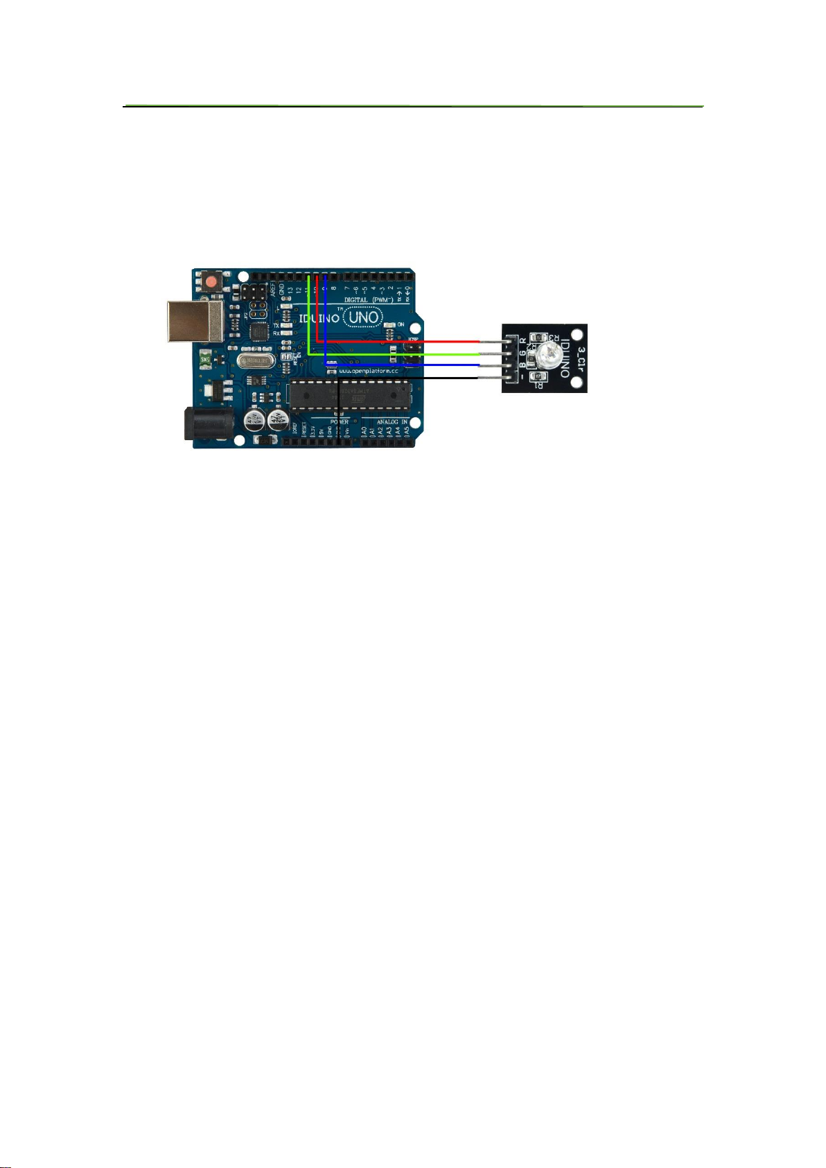
In this example, we blink an LED and using an RGB LED we can generate any color we
want.
Here is the physical connection:
********Code begin********
//RGB LED pins
int ledDigitalOne[] = {10, 11, 9}; //the three digital pins of the digital
LED
//10 = redPin, 11 = greenPin, 9 =
bluePin
const boolean ON = HIGH; //Define on as LOW (this is because we use
a common
//Anode RGB LED (common pin is connected to
+5 volts)
const boolean OFF = LOW; //Define off as HIGH
//Predefined Colors
const boolean RED[] = {ON, OFF, OFF};
const boolean GREEN[] = {OFF, ON, OFF};
const boolean BLUE[] = {OFF, OFF, ON};
const boolean YELLOW[] = {ON, ON, OFF};
const boolean CYAN[] = {OFF, ON, ON};
const boolean MAGENTA[] = {ON, OFF, ON};
const boolean WHITE[] = {ON, ON, ON};
const boolean BLACK[] = {OFF, OFF, OFF};
Page 3

IDUINO for Maker’s life
www.openplatform.cc
//An Array that stores the predefined colors (allows us to later randomly
display a color)
const boolean* COLORS[] = {RED, GREEN, BLUE, YELLOW, CYAN, MAGENTA, WHITE,
BLACK};
void setup(){
for(int i = 0; i < 3; i++){
pinMode(ledDigitalOne[i], OUTPUT); //Set the three LED pins as
outputs
}
}
void loop(){
/* Example - 1 Set a color
Set the three LEDs to any predefined color
*/
setColor(ledDigitalOne, YELLOW); //Set the color of LED one
/* Example - 2 Go through Random Colors
Set the LEDs to a random color
*/
//randomColor();
}
void randomColor(){
int rand = random(0, sizeof(COLORS) / 2); //get a random number within
the range of colors
setColor(ledDigitalOne, COLORS[rand]); //Set the color of led one to
a random color
delay(1000);
}
/* Sets an led to any color
led - a three element array defining the three color pins (led[0] =
redPin, led[1] = greenPin, led[2] = bluePin)
color - a three element boolean array (color[0] = red value (LOW = on,
HIGH = off), color[1] = green value, color[2] =blue value)
*/
void setColor(int* led, boolean* color){
for(int i = 0; i < 3; i++){
digitalWrite(led[i], color[i]);
}
Page 4

IDUINO for Maker’s life
www.openplatform.cc
}
void setColor(int* led, const boolean* color){
boolean tempColor[] = {color[0], color[1], color[2]};
setColor(led, tempColor);
}
********Code End********
 Loading...