

IDT Europe ZWIR4512AC1 User Manual

User Manual
Rev. 1.20 / August 2012
ZWIR451x
Serial Command Interface

ZWIR451x
Serial Command Interface – User Manual
User Manual
August 31, 2012
© 2012 Zentrum Mikroelektronik Dresden AG — Rev. 1.20
All rights reserved. The material contained herein may not be reproduced, adapted, merged, translated, stored, or used without the
prior written consent of the copyright owner. The information furnished in this publication is subject to changes without notice.
2 of 52
Contents
1 Introduction .......................................................................................................................................................... 6
1.1. Organization of this Document ..................................................................................................................... 6
2 Functional Description ......................................................................................................................................... 7
2.1. Interfaces ...................................................................................................................................................... 7
2.1.1. UART Interfaces ..................................................................................................................................... 7
2.1.2. SPI Interface .......................................................................................................................................... 8
2.1.3. Network Interface ................................................................................................................................... 8
2.2. Frame Format ............................................................................................................................................... 8
2.2.1. Commands and Responses ................................................................................................................... 9
2.2.2. Checksum Computation ......................................................................................................................... 9
2.2.3. Escaping................................................................................................................................................. 9
2.3. Frame Buffering .......................................................................................................................................... 10
2.4. Resets ......................................................................................................................................................... 10
2.5. Addressing .................................................................................................................................................. 10
2.5.1. PAN Identifier ....................................................................................................................................... 11
2.5.2. PAN Address ........................................................................................................................................ 11
2.5.3. IPv6 Addresses .................................................................................................................................... 11
2.6. The UDP Protocol ....................................................................................................................................... 14
2.7. Data Transmission and Reception ............................................................................................................. 14
2.8. Network Configuration ................................................................................................................................ 15
2.8.1. Physical Parameters ............................................................................................................................ 15
2.8.2. Software Parameters ........................................................................................................................... 15
2.9. Network Discovery ...................................................................................................................................... 18
2.10. Security ....................................................................................................................................................... 19
2.10.1. Internet Protocol Security (IPSec) ........................................................................................................ 19
2.10.2. Internet Key Exchange (IKEv2) ............................................................................................................ 21
2.10.3. Important Security Considerations and Recommendations ................................................................. 21
2.11. Firmware Over-the-Air Update (OTAU) ...................................................................................................... 21
2.12. General Purpose I/Os ................................................................................................................................. 22
2.13. Watchdog Timer ......................................................................................................................................... 23
2.14. Persistent Parameter Storage .................................................................................................................... 24
3 Command Reference ........................................................................................................................................ 25
3.1. Transmit Frame Command ......................................................................................................................... 26
3.2. Configure Receiver Command ................................................................................................................... 27
3.3. Get TRX Statistics ...................................................................................................................................... 28
3.4. Reset TRX Statistics ................................................................................................................................... 28
3.5. Configure Wake-up Command ................................................................................................................... 28
3.6. Power-Down Command.............................................................................................................................. 31
3.7. Get Address Configuration Command ........................................................................................................ 31
3.8. Set PAN Address ........................................................................................................................................ 32
3.9. Set PAN ID ................................................................................................................................................. 32
3.10. Configure PHY ............................................................................................................................................ 33
3.11. Configure Network ...................................................................................................................................... 34
3.12. Discover Network ........................................................................................................................................ 35

ZWIR451x
Serial Command Interface – User Manual
User Manual
August 31, 2012
© 2012 Zentrum Mikroelektronik Dresden AG — Rev. 1.20
All rights reserved. The material contained herein may not be reproduced, adapted, merged, translated, stored, or used without the
prior written consent of the copyright owner. The information furnished in this publication is subject to changes without notice.
3 of 52
3.13. Remote Execute ......................................................................................................................................... 35
3.14. Get Firmware Version ................................................................................................................................. 35
3.15. Reset........................................................................................................................................................... 36
3.16. Network Reset ............................................................................................................................................ 36
3.17. Store Configuration ..................................................................................................................................... 36
3.18. Test ............................................................................................................................................................. 37
3.19. Configure LEDs Command ......................................................................................................................... 37
3.20. Configure GPIO .......................................................................................................................................... 38
3.21. Write GPIO ................................................................................................................................................. 38
3.22. Read GPIO ................................................................................................................................................. 39
3.23. Toggle GPIO ............................................................................................................................................... 39
3.24. Configure UART1 ....................................................................................................................................... 40
3.25. Configure UART2 ....................................................................................................................................... 40
3.26. Configure SPI ............................................................................................................................................. 41
3.27. Restore Fabric Settings .............................................................................................................................. 42
3.28. Configure Multicast ..................................................................................................................................... 42
3.29. Join Multicast Group ................................................................................................................................... 43
3.30. Leave Multicast Group ................................................................................................................................ 43
3.31. Add Security Policy ..................................................................................................................................... 43
3.32. Add Security Association ............................................................................................................................ 44
3.33. Add IKEv2 Authentication Entry ................................................................................................................. 45
3.34. Enable Watchdog Timer ............................................................................................................................. 46
3.35. Get Current Interface .................................................................................................................................. 46
3.36. Get PHY Configuration ............................................................................................................................... 46
3.37. Get NET Configuration ............................................................................................................................... 47
3.38. Get FCC ID ................................................................................................................................................. 47
3.39. Receive Packet Command ......................................................................................................................... 47
3.40. Remote Response Command .................................................................................................................... 47
4 Certification ........................................................................................................................................................ 48
4.1. European R&TTE Directive Statements ..................................................................................................... 48
4.2. Federal Communication Commission Certification Statements ................................................................. 48
4.2.1. Statements ........................................................................................................................................... 48
4.2.2. Requirements ....................................................................................................................................... 48
4.3. Supported Antennas ................................................................................................................................... 49
5 Abbreviations ..................................................................................................................................................... 50
6 Related Documents ........................................................................................................................................... 51
7 Document Revision History ............................................................................................................................... 52

ZWIR451x
Serial Command Interface – User Manual
User Manual
August 31, 2012
© 2012 Zentrum Mikroelektronik Dresden AG — Rev. 1.20
All rights reserved. The material contained herein may not be reproduced, adapted, merged, translated, stored, or used without the
prior written consent of the copyright owner. The information furnished in this publication is subject to changes without notice.
4 of 52
List of Figures
Figure 2.1 Frame Format ........................................................................................................................................ 9
Figure 2.2 General IPv6 Address Layout .............................................................................................................. 12
Figure 2.3 IPv6 Multicast Address Layout ............................................................................................................ 12
Figure 2.4 Multicast Addressing: Group ID Configuration..................................................................................... 14
Figure 2.5 Example of Network Topology 1 .......................................................................................................... 16
Figure 2.6 Example of Network Topology 2 .......................................................................................................... 17
Figure 2.7 IPSec Working Principle ...................................................................................................................... 20
Figure 2.8 Layout of the Pin Configuration Bit-Field ............................................................................................. 23
Figure 3.1 Configure Wakeup - Peripheral Field Format ...................................................................................... 30
Figure 3.2 Remote Execute Command Frame Layout ......................................................................................... 35
Figure 3.3 UART Configuration Bit-Field Layout ................................................................................................... 40
Figure 3.4 SPI Configuration Bit-Field Layout ....................................................................................................... 41
Figure 8.1 FCC Compliance Statement to be printed on Equipment Incorporating ZWIR4512 Devices ............. 49
List of Tables
Table 2.1 Interface Dispatch Numbers .................................................................................................................. 7
Table 2.2 UART Configuration and Pin Description .............................................................................................. 7
Table 2.3 UART Configuration Options ................................................................................................................. 7
Table 2.4 SPI Pin Description ................................................................................................................................ 8
Table 2.5 SPI Configuration Options ..................................................................................................................... 8
Table 2.6 General Error Responses ...................................................................................................................... 9
Table 2.7 GPIO Operating Modes ....................................................................................................................... 22
Table 2.8 Default I/O Configuration of Preconfigured Pins .................................................................................. 22
Table 3.1 Command Overview ............................................................................................................................ 25
Table 3.2 Transmit Frame Command Fields ....................................................................................................... 26
Table 3.3 Transmit Frame Command Responses ............................................................................................... 27
Table 3.4 RXSetup Command Fields .................................................................................................................. 27
Table 3.5 RXSetup Command Responses .......................................................................................................... 27
Table 3.6 Get TRX Statistics Response Format .................................................................................................. 28
Table 3.7 Transmission Duty-Cycle Requirements of Sub-GHz Devices in the European Union ...................... 28
Table 3.8 Wakeup Sources .................................................................................................................................. 29
Table 3.9 Configure Wakeup Command Fields ................................................................................................... 30
Table 3.10 Configure Wakeup Command Responses .......................................................................................... 30
Table 3.11 Power Down Command Fields ............................................................................................................ 31
Table 3.12 Power Down Command Responses .................................................................................................... 31
Table 3.13 Get Address Configuration Response Fields....................................................................................... 32
Table 3.14 Set PAN Address Command Fields ..................................................................................................... 32
Table 3.15 Set PAN Address Command Responses ............................................................................................ 32
Table 3.16 Set PAN ID Command Fields .............................................................................................................. 33
Table 3.17 Set PAN ID Command Responses ...................................................................................................... 33
Table 3.18 Configure PHY Command Fields ......................................................................................................... 33
Table 3.19 Configure PHY Command Responses ................................................................................................ 33
Table 3.20 Configure Network Command Fields ................................................................................................... 34

ZWIR451x
Serial Command Interface – User Manual
User Manual
August 31, 2012
© 2012 Zentrum Mikroelektronik Dresden AG — Rev. 1.20
All rights reserved. The material contained herein may not be reproduced, adapted, merged, translated, stored, or used without the
prior written consent of the copyright owner. The information furnished in this publication is subject to changes without notice.
5 of 52
Table 3.21 Response Codes of the Configure Network Command ....................................................................... 35
Table 3.22 Remote Execute Response Codes ...................................................................................................... 35
Table 3.23 Get Firmware Version Command Responses ..................................................................................... 36
Table 3.24 Store Configuration Command Fields .................................................................................................. 36
Table 3.25 Store Configuration Command Responses ......................................................................................... 37
Table 3.26 Test Command Fields .......................................................................................................................... 37
Table 3.27 Test Command Responses ................................................................................................................. 37
Table 3.28 Configure LEDs Command Fields ....................................................................................................... 37
Table 3.29 Configure LEDs Command Responses ............................................................................................... 38
Table 3.30 Configure GPIO Command Fields ....................................................................................................... 38
Table 3.31 Configure GPIO Responses ................................................................................................................ 38
Table 3.32 Write GPIO Command Fields .............................................................................................................. 38
Table 3.33 Write GPIO Responses ........................................................................................................................ 39
Table 3.34 Read GPIO Command Fields .............................................................................................................. 39
Table 3.35 Read GPIO Command Responses ...................................................................................................... 39
Table 3.36 Toggle GPIO Command Fields ............................................................................................................ 39
Table 3.37 Toggle GPIO Command Responses ................................................................................................... 39
Table 3.38 Configure UART Command Fields ...................................................................................................... 40
Table 3.39 Configure UART Command Responses .............................................................................................. 40
Table 3.40 Configure SPI Command Fields .......................................................................................................... 41
Table 3.41 Configure SPI Command Responses .................................................................................................. 41
Table 3.42 Restore Fabric Settings Command Fields ........................................................................................... 42
Table 3.43 Restore Fabric Settings Command Responses................................................................................... 42
Table 3.44 Configure Multicast Command Fields .................................................................................................. 42
Table 3.45 Configure Multicast Command Fields .................................................................................................. 42
Table 3.46 Join Multicast Group Command Fields ................................................................................................ 43
Table 3.47 Join Multicast Field Command Responses .......................................................................................... 43
Table 3.48 Leave Multicast Group Command Fields ............................................................................................. 43
Table 3.49 Leave Multicast Group Command Responses .................................................................................... 43
Table 3.50 Add Security Policy Command Fields .................................................................................................. 44
Table 3.51 Add Security Policy Command Responses ......................................................................................... 44
Table 3.52 Add Security Association Command Fields ......................................................................................... 45
Table 3.53 Add Security Association Command Responses ................................................................................ 45
Table 3.54 Add IKEv2 Authentication Entry Command Fields .............................................................................. 45
Table 3.55 Add IKEv2 Authentication Entry Command Responses ...................................................................... 46
Table 3.56 Enable Watchdog Timer Command Fields .......................................................................................... 46
Table 3.57 Get PHY Command Response ............................................................................................................ 46
Table 3.58 Get NET Command Response ............................................................................................................ 47
Table 3.59 Receive Packet Command Fields ........................................................................................................ 47
Table 3.60 Remote Response Command Fields ................................................................................................... 47

ZWIR451x
Serial Command Interface – User Manual
User Manual
August 31, 2012
© 2012 Zentrum Mikroelektronik Dresden AG — Rev. 1.20
All rights reserved. The material contained herein may not be reproduced, adapted, merged, translated, stored, or used without the
prior written consent of the copyright owner. The information furnished in this publication is subject to changes without notice.
6 of 52
1 Introduction
This document describes the features and the usage of the ZWIR451x module with the Serial Command Interface
(SCI) firmware. The SCI allows using ZWIR451x modules without programming the module. The ZWIR451x
modules are delivered preprogrammed and tested and can be integrated into the application without
programming. The module provides several serial interfaces that can be used independently to control the
module.
The SCI module provides firmware over-the-air update (OTAU) capability, data encryption, and data
authentication in addition to the normal User Datagram Protocol (UDP) communication. Integration into normal
computer networks is possible without restrictions.
1.1. Organization of this Document
The following section gives a functional overview of the serial command interface firmware. The different interfaces, mechanisms, and functionalities are explained in this section. Section 3 documents all available
commands.
In order to differentiate between decimal, hexadecimal, and binary number representations, this document uses
the convention to subscript binary and hexadecimal numbers with a capital B or H, respectively.
In section 3, command argument fields and responses are explained in a table format. Interpret tables for
command argument fields as a list: the first table row is the first command argument; the second row represents
the second argument, and so on. For responses, the same rule applies if there is no code field in the table.
Otherwise, the table is interpreted in the following way: The code is the first field contained in the response. All
fields (second column of the table) in the same row as the code field follow the code in the response.

ZWIR451x
Serial Command Interface – User Manual
User Manual
August 31, 2012
© 2012 Zentrum Mikroelektronik Dresden AG — Rev. 1.20
All rights reserved. The material contained herein may not be reproduced, adapted, merged, translated, stored, or used without the
prior written consent of the copyright owner. The information furnished in this publication is subject to changes without notice.
7 of 52
Interface
Dispatch Value
UART1
0
UART2
1
SPI
2
Network
3
UART-Pin Name
Usage
Direction
Module Pin
UART1
UART2
Transmit (TX)
Mandatory
Output
13 6 Receive (RX)
Mandatory
Input
12
5
Request to send (RTS)
Optional
Output
17
7
Clear to send (CTS)
Optional
Input
16
8
Option
Default Configuration
Configuration Options
Data Transfer Rate
115200 Baud
61
(1)
baud – 256000
(2)
baud
Parity
Not enabled
Odd, Even
Number of Stop Bits
1 2 Flow-Control
Not enabled
Hardware Flow Control
(1) 61 baud can only be achieved on UART2. The minimum baud rate of UART1 is 122.
(2) The maximum rate of 256000 baud can only be achieved on UART1. The maximum rate of UART2 is 115200 baud.
2 Functional Description
2.1. Interfaces
The module provides two UART and one SPI interface for communication with external hosts. The host can also
execute commands over the network interface. Hosts can be computers, microcontrollers, or even single sensors
that have an appropriate interface. It is possible to connect different devices to different interfaces. All
communication interfaces are enabled in the SCI default configuration.
The SCI firmware allows sending incoming network data to any of the available interfaces. For this purpose, the
Configure Receiver command expects a dispatch value that specifies to which of the serial interfaces incoming
data is sent. Table 2.1 shows the dispatch numbers for the different interfaces.
Table 2.1 Interface Dispatch Numbers
2.1.1. UART Interfaces
The module provides two UART interfaces. By default, both interfaces operate at a data rate of 115200 kBaud,
have 8 data bits, one stop bit, no parity bit, and no flow control. The UART configuration can be changed at any
time using one of the commands Configure UART1 or Configure UART2. Any interface can be used to change the
UART configuration.
Table 2.2 UART Configuration and Pin Description
Table 2.3 UART Configuration Options

ZWIR451x
Serial Command Interface – User Manual
User Manual
August 31, 2012
© 2012 Zentrum Mikroelektronik Dresden AG — Rev. 1.20
All rights reserved. The material contained herein may not be reproduced, adapted, merged, translated, stored, or used without the
prior written consent of the copyright owner. The information furnished in this publication is subject to changes without notice.
8 of 52
SPI Pin Name
Direction
Usage
Module Pin
Master Out Slave In (MOSI)
Input
Mandatory
1
Master In Slave Out (MISO)
Output
Mandatory
2
Clock
Input
Mandatory
3
Slave Select
Input
Optional
4
Data Pending
Output
Optional
7
Value
Default
Configuration Option
Clock Polarity
Low ( clock is low when idle )
High
Clock Phase
First edge captures data
Second edge captures data
Pending Pin Mapping
Module pin 7
2.1.2. SPI Interface
The module provides an SPI interface that is operating in slave mode. To control the SCI module via the SPI, the
host computer must provide an SPI clock whenever data is to be sent or received. Availability of data from the SCI
module is signaled by a dedicated line that is pulled low when data is available for read-out. If the host needs to
receive data and no data is to be transmitted, sending zeros is recommended. The ZWIR451x will send zeros
over its MISO line if the master is transmitting a frame and no data has to be transmitted to the host.
The default configuration uses the SSN pin to activate the SCI node. Data is only received and transmitted if the
SSN pin is pulled to low. The SPI is configured for MSB first transmission and reception; the clock is low when
idle; and the first clock transition is used as data capture edge.
Table 2.4 SPI Pin Description
Table 2.5 SPI Configuration Options
2.1.3. Network Interface
The network interface allows executing commands remotely. Basically this works like the serial interfaces with the
difference that command frames sent over the network interface do not have to carry the START byte and data
escaping is not required. All available commands can be executed remotely. For some commands restrictions
apply.
Each SCI node listens to UDP port 4 for incoming command frames. If a command is received, it is executed and
if there is any response from the command, the response is sent back to the device that requested execution of
the command.
The SCI also implements the Remote Execute command, which allows initiation of a remote execution over one of
the serial interfaces.
2.2. Frame Format
Command and responses are sent over the different physical communication interfaces in data frames that have a
special format that allows detecting communication errors and introduces low overhead. All frames have a
common format.
The frame format is illustrated in Figure 2.1. Each frame starts with the START delimiter 7EH. The following two
bytes determine the length of the frame payload. Length information is stored in Little Endian format; hence, the
least significant byte is stored first. The third byte determines the command to be executed. The following N bytes

ZWIR451x
Serial Command Interface – User Manual
User Manual
August 31, 2012
© 2012 Zentrum Mikroelektronik Dresden AG — Rev. 1.20
All rights reserved. The material contained herein may not be reproduced, adapted, merged, translated, stored, or used without the
prior written consent of the copyright owner. The information furnished in this publication is subject to changes without notice.
9 of 52
Code
Field
Length
Description
1
Invalid Header
3
Message larger than the maximum allowed size or unknown command.
2 - Invalid checksum.
3
Interface
1
A framing, parity, overflow, or noise error at the UART or SPI interface
occurred.
Command
1
Pos. of Last Valid Byte
2 4 Internal Error Code
4
An internal error occurred.
5 - Duplicate address detection failed.
30
Failing IPv6 Address
16
The address resolution for the address returned in the response failed.
This error occurs sometime after attempting to send an unicast frame to a
destination.
START
1 byte
LENGTH
2 bytes
CMD
1 byte
CHKS
1 byte
PAYLOAD
LENGTH bytes
are the frame payload. At the end of the frame, a checksum byte is attached, which helps to detect communication errors.
Figure 2.1 Frame Format
2.2.1. Commands and Responses
The Serial Command Interface firmware distinguishes Command and Response Frames. Command Frames are
sent in order to trigger a specific action at the receiver of the Command Frame. Response Frames contain status
information sent in response to Command Frames. Typically Response Frames are only sent if an error was
encountered in the last Command Frame.
A Command Frame has a Command Code in the range of 01H to 7FH. The values 00H, 1BH and 7EH are not
allowed. An overview of all available commands and their command codes can be found in Table 3.1.
The Command Code of a Response Frame is the Command Code of the Command Frame that triggered the
Response OR’ed with 80H. The Response Frame with the Command Code 80H is a special response frame that is
sent when an invalid frame was received or another non-command-related error occurred.
Table 2.6 General Error Responses
2.2.2. Checksum Computation
At the end of each packet a checksum is appended that helps to detect transmission errors on the physical
transmission medium. The checksum is formed in such way that the sum of all transmitted bytes, excluding the
Start character 7EH is zero. If the sum of all received bytes of a packet does not result in zero, a Frame Error
packet with its error code set to CHECKSUM_ERROR is sent over the same interface the erroneous packet was
received on.
2.2.3. Escaping
If one of the characters 1BH or 7EH is contained in the data stream or one of the frame control fields, this character
must be escaped by XOR’ing it with 80H and prepending it with 1BH. This modification has no effect on the length
field of the frame, even if it is done in the payload section of the frame. However, escaping must be considered for
checksum calculation.

ZWIR451x
Serial Command Interface – User Manual
User Manual
August 31, 2012
© 2012 Zentrum Mikroelektronik Dresden AG — Rev. 1.20
All rights reserved. The material contained herein may not be reproduced, adapted, merged, translated, stored, or used without the
prior written consent of the copyright owner. The information furnished in this publication is subject to changes without notice.
10 of 52
If the checksum of the device is one of ZMDI’s two control characters, the checksum must be escaped as well.
Escaping the checksum is done by sending the escape character 1BH followed by the computed checksum value
minus 1BH
The following examples illustrate how escaping must be performed:
7e 04 00 12 1a 1b 1c 1d 7c
7e 04 00 12 1a 1b 9b 1c 1d e1
7e 1b 00 01 ff 02 00 00 00 00 00 00 00 00 00 00 00 00 00 01 7e 03 01 02 03 04 05 06 07 08 09 34
7e 1b 9b 00 01 ff 02 00 00 00 00 00 00 00 00 00 00 00 00 00 01 1b fe 03 01 02 03 04 05 06 07 08 09 fe
7e 04 00 10 24 9f 32 79 7e
7e 04 00 10 24 9f 32 79 1b 63
2.3. Frame Buffering
Each communication interface maintains its own message queue. In situations of high load, messages are
queued temporarily in the message queue. Each interface has its own message queue. The message queue
distinguishes between command frames and response frames. Response frames are queued at the beginning of
the queue, while command frames are queued at the end of the queue. This ensures that response frames are
sent immediately after the triggering command frame. However, if a command frame is being sent when a
response frame is queued, the transmission of the command frame is completed before the response frame is
sent.
2.4. Resets
The SCI module provides two types of reset. One is System Reset; the other one is Network Reset. System Reset
puts the device into the state that it has after a power-on. It executes the complete startup procedure of the
microcontroller and the transceiver in order to put them into a defined state. All settings are restored to the fabric
default values or to the configuration that was saved to the flash memory the last time. System Reset is also
performed automatically in the event of an unrecoverable error. If System Reset is performed because of an error,
an error message is sent over the interface the last instruction was received from. This message usually contains
an error description. The most common error for System Reset is a memory allocation failure, which can appear
after changing the network configuration or after configuring multicast. Refer to the documentation of the
Configure Network and Configure Multicast commands.
Network Reset is used after changing the network configuration. It does not perform a System Reset. A Network
Reset disconnects all open connections and applies changes in network parameters that have been applied
before. The command Configure Network performs a reset automatically to apply the settings that have been
made. Network Reset does not affect the physical parameter set with Configure PHY.
2.5. Addressing
Each SCI module has three types of addresses. The PAN Identifier, the PAN Address and the IPv6 Address(es)
are described in the following sections.

ZWIR451x
Serial Command Interface – User Manual
User Manual
August 31, 2012
© 2012 Zentrum Mikroelektronik Dresden AG — Rev. 1.20
All rights reserved. The material contained herein may not be reproduced, adapted, merged, translated, stored, or used without the
prior written consent of the copyright owner. The information furnished in this publication is subject to changes without notice.
11 of 52
2.5.1. PAN Identifier
This address identifies the network the device is operating in. All devices that are part of the same network must
use the same PAN identifier. Devices with different PAN identifiers are not able to communicate with each other,
even if they are in the physical range of each other and have the same PHY settings applied.
The PAN Identifier is a 16-bit number. Its default value is ACCAH. This value is changed using the command Set
PAN ID.
2.5.2. PAN Address
The PAN address is the hardware address of the device. The PAN address is also commonly known as the MAC
address. The PAN address of the SCI module is a 64-bit number that is formed according to the EUI-64 rules.
Each device in the network MUST have a unique PAN address. This address is used to generate locally and
globally unique IPv6 addresses (see section 2.5.3.1). Usually applications do not have to process the PAN
address directly.
ZMDI’s ZWIR451x SCI Modules have a globally unique address preprogrammed. This enables generation of
locally and globally unique IPv6 addresses without any need for initial configuration. ZMDI does not recommend
changing the PAN address of the device. However, if the application requires this, it is supported by the command
Set PAN Address.
2.5.3. IPv6 Addresses
The IPv6 addresses are the addresses the applications are dealing with. These addresses are 128-bit wide. Each
device must have at least one IPv6 address in order to be able to communicate. Using IPv6 addresses, the
application determines where packets are sent to and received from. How IPv6 addresses are set up and how
they are presented is explained below.
IPv6 addresses are 128-bit, thus 16-byte wide. As it would be impractical to use the byte-wise notation known
from the old IPv4, IPv6 introduces a new notation. IPv6 addresses are represented by eight 16-bit hexadecimal
numbers that are separated by colons. An example for such address is
2001:0db8:0000:0000:1b00:0000:0ae8:52f1
Leading zeros of segments can be omitted as they do not carry information. The IPv6 notation allows omitting a
sequence of zero-segments and representing it as double colon. With these rules, the above address can be
written as
2001:db8::1b00:0:ae8:5211 or 2001:db8:0:0:1b00::ae8:52f1.
However, replacing multiple zero segments is not allowed. Thus the address
2001:db8::1b00::ae8:5211
is invalid.
In order to explain IPv6 addresses, the term “link” must be defined. Nodes are said to be on the same link when
they are able to communicate with each other without requiring any routers. Nodes on the same link are able to
communicate on the MAC level.
An IPv6 address consists of two components: a prefix and an interface identifier. The prefix specifies the network
a device is part of while the interface identifier specifies the interface of a device. The size of the prefix varies for
different address types. In the IPv6 address notation, the prefix length can be appended to the address with a
slash followed by the number of prefix bits. Thus the notation 2001:db8::/64 represents a network containing the
addresses from 2001:db8:: to 2001:db8::ffff:ffff:ffff:ffff.

ZWIR451x
Serial Command Interface – User Manual
User Manual
August 31, 2012
© 2012 Zentrum Mikroelektronik Dresden AG — Rev. 1.20
All rights reserved. The material contained herein may not be reproduced, adapted, merged, translated, stored, or used without the
prior written consent of the copyright owner. The information furnished in this publication is subject to changes without notice.
12 of 52
Prefix
127
0
Group Identifier (GID)
FFH
Scope
Flags
112
116
120
127
112
Prefix
127 n n-1
0
Interface Identifier (IID)
Figure 2.2 General IPv6 Address Layout
IPv6 supports three kinds of addressing methodologies: unicast addressing, multicast addressing, and anycast
addressing. Unicast addressing is used to communicate to well defined remote nodes. Using multicast addressing
packts may be sent to multiple addresses at the same time. Anycast addressing is used to reach any node out of
a group of nodes which share the same anycast address. ZMDI’s SCI firmware doesn’t allow nodes to have
anycast addresses. However, remote anycast nodes (e.g. compuers in the network) can be reached. A network
node may have multiple interfaces; e.g. it may incorporate multiple radio nodes or multiple Ethernet cards. Unicast
addresses are used to address a single interface in the network. The prefix of the address determines the scope
of the unicast address. This may be link-local or global. All unicast addresses with a prefix starting with 0b000
(bits 125 to 127) have a 64-bit interface identifier. If the prefix equals fe80::/64, this is a link-local unicast address.
Link local addresses are valid only on the link the interface is connected to. The prefix of global unicast addresses
is typically received from a router via address autoconfiguration. If the router is not connected to the internet, the
node will not get a global address, only a local one. Besides local and global prefixes, there are further prefix
configurations with limited scope that are not covered by this documentation. Refer to RFC 4291 for more detailed
information about alternative prefix configurations.
Multicast allows sending packets to multiple receivers at the same time. For this purpose, IPv6 provides multicast
addresses. This class of addresses must only be used as destination address. It MUST NOT be used as a source
address in IPv6 packets. Figure 2.3 shows the layout of multicast addresses. They have a 16-bit prefix with the
most significant eight bits set to ffH, followed by two 4-bit fields for flags and the scope of the multicast packet. The
lower 112 bits specify the multicast group id. A device checks if it is part of a multicast group depending on the
multicast group ID.
Figure 2.3 IPv6 Multicast Address Layout
For the flags field, ZMDI’s IPv6 stack only supports the values 0000B and 0001B. The first version specifies that
the multicast address is a well-known address (an address that has been assigned by the IANA). The second one
marks the address as a temporarily assigned address that is not specified by internet standards. Custom multicast
addresses MUST use the latter version of multicast addresses!
For the scope field, any allowed value is supported. However values above 0010B require appropriately configured
routers.
Two addresses are of special interest, as they are used very often.
1. The unspecified address :: - All segments of this address are zero. It is used by receivers to listen to any
sender. This address must never be used as destination address.
2. The link-local all nodes multicast address ff02::1 – Packets sent to this address are received by all nodes
on the link. Thus this multicast address is equivalent to link-local broadcasting.
For further information about IPv6 addressing, refer to RFC 4291 – “IP Version 6 Addressing Architecture.”

ZWIR451x
Serial Command Interface – User Manual
User Manual
August 31, 2012
© 2012 Zentrum Mikroelektronik Dresden AG — Rev. 1.20
All rights reserved. The material contained herein may not be reproduced, adapted, merged, translated, stored, or used without the
prior written consent of the copyright owner. The information furnished in this publication is subject to changes without notice.
13 of 52
2.5.3.1. IPv6 Address Autoconfiguration
In order to make node configuration and setup as easy as possible, IPv6 provides a stateless autoconfiguration
mechanism for IPv6 addresses. Using this algorithm, IPv6 unicast addresses are generated automatically from
information statically available on the interface and information provided by routers on the link. If no router is
present, only an IPv6 address with link-local scope is generated. Global addresses are generated if the router
advertises prefix information. Thus, no manual address assignment is required and no server-based address
assignment technology, such as DHCP, needs to be provided.
The stateless address autoconfiguration mechanism uses the PAN address (refer to section 2.5.2) of the interface
to generate the device’s IPv6 addresses. For both address scopes, link-local and global scope, this is done by
putting a 64-bit prefix in front of the modified 64-bit PAN address of the interface. The modification of the PAN
address refers to toggling the universal/local bit of the interface identifier. This method is described in Appendix A
of RFC 4291. Assuming a PAN address of 00:11:7d:00:00:12:34:56 and a prefix 2001:db8::/64, this would result
in the global IPv6 address 2001:db8::211:7d00:12:3456. Accordingly the link-local address would be generated by
using the link-local prefix fe80::/64 and result in the IPv6 address fe80::211:7d00:12:3456. Note that in both
cases, the modification coming from the modified PAN address is highlighted in red.
IPv6 requires that addresses that are assigned to an interface are checked for their uniqueness on the link. This is
done using the Duplicate Address Detection (DAD) algorithm. DAD is not required if the universal/local bit in the
interface identifier of the IPv6 address is set to 1 (like in the example above). The DAD algorithm is described in
more detail in section 2.5.3.3.
2.5.3.2. Multicast
IPv6 Multicast allows sending packets to multiple receivers at the same time. Sending packet to multiple receivers
is done by simply using a multicast address as the destination address. All devices that want to receive packets
sent to a particular multicast address must join the appropriate multicast group before they are able to receive
packets. The receiver must be configured appropriately to receive packets from the sender. Refer to section 2.7
for more detailed information on configuring devices for data reception.
The ZWIR451x SCI firmware provides a flexible multicast implementation supporting up to 16384 (214) groups.
Depending on the multicast configuration of the device, 7 to 112 groups can be accessed simultaneously. When
multicast is configured, a bit-field is allocated in the devices with each bit representing the status of a certain
group membership status of the device. Joining a certain group will set the corresponding bit in the bit-field
internally, while leaving that group will delete the bit. Each device can join as many groups as it wishes.
In order to send data to one or multiple groups, the destination address must be formed appropriately according to
the selected multicast configuration. ZMDI’s multicast implementation allows flexible configuration of the way
multicast groups are addressed in the network. The multicast GID basically is divided into two sections. The lower
bits are interpreted as a bit mask that is logically AND’ed with the internally stored bit-field of a receiving device in
order to determine if the device is part of the requested multicast group. The remaining bits that are not in the bitmask are interpreted as 16-bit group addresses. Each multicast device MUST configure multicast. During the
multicast configuration, specify how many of the upper 16 fields of an IPv6 multicast address are interpreted as
the group address. The remaining bits are interpreted as bit-field. The general layout of the multicast GID is
shown in Figure 2.4. Parameter N is the configured number of group address fields. Note that all devices in the
network must use the same multicast configuration.

ZWIR451x
Serial Command Interface – User Manual
User Manual
August 31, 2012
© 2012 Zentrum Mikroelektronik Dresden AG — Rev. 1.20
All rights reserved. The material contained herein may not be reproduced, adapted, merged, translated, stored, or used without the
prior written consent of the copyright owner. The information furnished in this publication is subject to changes without notice.
14 of 52
Prefix
127
0
Group Identifier (GID)
GADR
N-1
112 – 16
112
GADR0
Group Bit-Mask (112 – N*16 bits)
112 – N*16
0
Figure 2.4 Multicast Addressing: Group ID Configuration
2.5.3.3. Validation of IPv6 Address Uniqueness
Duplicate address detection (DAD) is performed to check if an IPv6 address is unique on the link. For this
purpose, a node starts to send neighbor solicitation (NS) messages to the address to be checked. If another node
replies to one of those messages or if another node also sends neighbor solicitation messages to this address,
the assigned address is not unique and must not be used. In such cases, a system reset is performed, and an
error message is sent to the interface that the last command was received from. Note that this error can only
happen if some of the devices in the application use manually configured IPv6 addresses or PAN addresses.
Therefore, it is recommended that manually configured addresses not be used!
2.6. The UDP Protocol
The User Datagram Protocol (UDP) is used for data transmission in ZWIR451x devices. UDP is a connectionless
and lightweight protocol, introducing minimal communication and processing overhead. No connection has to be
created, and no network traffic is required before data transmission between nodes can be started. Instead,
communication is possible immediately. UDP does not guarantee that packets that have been sent are reaching
the receiver. If reliable transmission is required, acknowledges must be implemented on the application level. It is
also possible that the same UDP packet is received multiple times. Furthermore, it is not guaranteed that the
receive order of packets at the destination is the same as the send-order at the source. This must be considered
by the application programmer.
UDP uses the concept of ports to differentiate different data streams to a node. A port can be seen as the address
of a service running on the receiver of a packet. Depending on the destination port of a packet, the network stack
decides to which network service the packet is routed. UDP distinguishes 65636 ports. The SCI firmware on
ZWIR451x simply transmits data that have been received on a certain connection to one of its interfaces. It is
possible to assign different interfaces to different ports.
The SCI firmware opens three UDP connections automatically. These connections are required for the remoteexecution of commands, the Internet Key Exchange protocol, and the Over-the-Air firmware update feature. The
ports allocated for these services are listed below. They must not be used by the application.
Port 4: Remote Execution
Port 500: Internet Key Exchange version 2
Port 1357: Over-the-Air Update
2.7. Data Transmission and Reception
Data transmission is requested with the Transmit Data command. This command allows specification of the
destination IPv6 address and the UDP port that the packet should be sent to. The source port of the transmission
is selected randomly.
In order to receive packets from a remote device, the receiver must be configured appropriately. For that purpose,
the command Configure Receiver is provided. It allows configuring the source address of the device that data
should be received from and the UDP port that data should be received on. It is possible to determine to which

ZWIR451x
Serial Command Interface – User Manual
User Manual
August 31, 2012
© 2012 Zentrum Mikroelektronik Dresden AG — Rev. 1.20
All rights reserved. The material contained herein may not be reproduced, adapted, merged, translated, stored, or used without the
prior written consent of the copyright owner. The information furnished in this publication is subject to changes without notice.
15 of 52
interface that data traffic received on the particular connection is sent to. The source address argument SHOULD
be a unicast address, if data reception from a particular device is expected. Alternatively it is possible to use the
unspecified address that will accept data from any sender.
For successful data transmission, the UDP port configured at the receiver must match the UDP port that data is
sent to.
2.8. Network Configuration
ZWIR451x network parameters are configurable to match the needs of the application. Especially for large
installations with mesh routing, adjusting settings for optimal performance is strongly recommended.
2.8.1. Physical Parameters
ZWIR451x’s SCI firmware allows configuring the radio channel, the signal modulation, and the transmission
power. In order to be able to communicate, all devices must use the same channel and modulation settings. All
physical parameters are changed with the command Configure PHY.
Note that the European Union restricts the output power of devices in the SRD extension band (865 MHz – 868
MHz) to 1 mW. For that reason, it is not possible to select an output power of more than 0dBm for these bands.
Otherwise an error message is returned.
2.8.2. Software Parameters
The software parameters control the behavior of the network stack. All of these parameters are changed using the
command Configure NET.
2.8.2.1. IPv6 Network Parameters
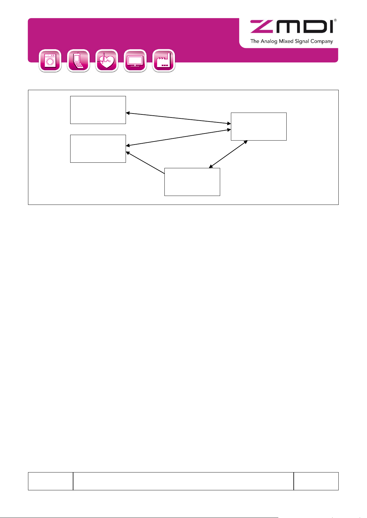
The Neighbor Cache Size determines how many neighbor cache entries are allocated by the network. Neighbor
cache entries are required for each remote endpoint a device wishes to communicate via unicast to. Considering
an example network topology as shown in Figure 2.5, the devices must have the following number of neighbor
cache entries:
D1 1 entry
D2 1 entry
D3 2 entries
D4 3 entries
Thus for each outgoing connection (arrow is pointing away from device), a neighbor cache entry is required.
ZWIR451x
Serial Command Interface – User Manual
User Manual
August 31, 2012
© 2012 Zentrum Mikroelektronik Dresden AG — Rev. 1.20
All rights reserved. The material contained herein may not be reproduced, adapted, merged, translated, stored, or used without the
prior written consent of the copyright owner. The information furnished in this publication is subject to changes without notice.
16 of 52
D1
D2
D3
D4
Figure 2.5 Example of Network Topology 1
The Maximum Socket Count parameter determines how many sockets may be open at the same time. This is
important for concurrent reception of different data streams.
The Neighbor Reachable Time parameter determines the time a neighbor cache entry is considered as
reachable before reachability is verified by the network stack automatically. Usually this parameter is configured
by routers present in the network. Thus, if a router is present, the configured value is overwritten with the value
received from router advertisements.
The Duplicate Address Detection Enable flag determines if duplicate address detection (DAD) is performed
during interface initialization or when a new address is assigned to the interface. Duplicate address detection is
used to verify that no other device in the network is using the same address as the address verified. DAD causes
one broadcast packet to be sent during interface initialization. The interface is not available for user communication before the DAD packet is sent and some delay to receive an answer has passed. The time before
availability of the interface or a newly assigned IPv6 address is between one and two seconds if DAD is enabled.
If DAD is disabled, the interface or newly assigned addresses are available immediately and no packet is sent out
by the device. However, leaving DAD enabled is recommended for protection from network failures caused by
duplicate addresses. A device that is unable to initialize its interface correctly will report an error and go to
Standby Mode until it is being reset.
The Router Solicitation Enable flag determines if the device sends router solicitations to the network. This is
typically done to obtain network configuration information such as address lifetimes and reachable times as well
as global network prefixes. If there will never be a router on the network, this option can be disabled. Otherwise
the option should be left enabled. Usually routers send configuration information autonomously at a certain time
interval. If delayed reception of router information is acceptable, the Router Solicitation Enable flag may be unset.
However, care must be taken to ensure that the router information advertised on a regular basis contains the
same amount of information as the solicited advertisements.
 Loading...