

Page 1
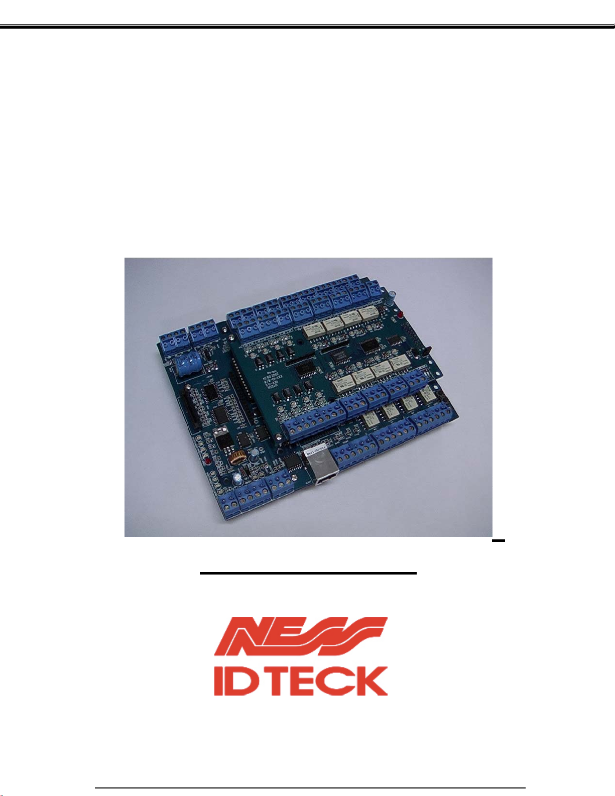
IDTeck
ITDC
ITDCSR
EIO88
Access Controller
Rev. V3.x
USER’S MANUAL
The specification contained in this manual are subject to change without notice at any time.
Page 2

Table of Contents
1. IMPORTANT SAFETY INSTRUCTIONS
2. INTRODUCTION
2.1 IDENTIFYING SUPPLIED PARTS
2.2 ABOUT NESS - IDTECK iTDC
2.3 SPECIFICATION
3. PRODUCT OVERVIEW
3.1 FUNCTIONS
3.2 BOARD LAYOUT
3.3 OPTIONAL ACCESSORIES
3.3.1 EIO88 EXPANSION I/O BOARD
3.3.2 TCP/IP MODULE
3.3.3 LCD DISPLAY MODULE
3.3.4 KEYPAD
4. INSTALLATION TIPS & CHECK POINT
4.1 CHECK POINTS BEFORE INSTALLATION
4.1.1 CABLE/WIRE
4.1.2 TIPS FOR PLACING DEVICES
4.2 CHECK POINTS DURING INSTALLATION
4.2.1 TERMINATING RESISTANCE
4.2.2 DISCCORD OF ELECTRIC POTENTIAL
4.2.3 EARTH GROUND
4.3 TIPS TO MAXIMIZE READ RANGE OF RFID READERS
4.3.1 POWER SUPPLY
4.3.2 ENVIRONMENTAL SOURCES OF
ELECTRICAL INTERFERENCE.
4.4 INSTALLATION LOCATION
5. INSTALLATION
5.1 DIMENSIONS
5.2 BACKUP BATTERY JUMPER
5.3 DIP SWITCH (BOARD ID)
5.4 WIRING
5.4.1 POWER
5.4.2 INPUT CONNECTIONS
5.4.3 OUTPUT CONNECTIONS
5.4.4 READER CONNECTIONS
5.4.5 OPTIONAL ACCESSORY CONNECTIONS
6. COMMUNICATIONS
6.1 RS232 COMMUNICATION PORT CONNECTION
Page 3

IDTeck – iTDC 2~4 DOOR ACCESS CONTROLLER
6.2 RS-422 COMMUNICATION PORT CONNECTION
6.2.1 RS-422 COMMUNICATION (STANDALONE)
6.2.2 RS-422 COMMNUNICATION
(MULTIPLE iTDC CONNECTIONS)
6.3 DIAL UP MODEM
6.4 TCP/IP MODULE (INTERNAL VERSION)
6.5 TCP/IP CONVERTER (EXTERNAL VERSION)
7. OPERATION STATUS
7.1 LED INDICATORS OF THE iTDC
7.2 LED INDICATORS OF THE EIO88 EXPANSION I/O BOARD
8. BASIC SETTINGS
8.1 INITIALIZATION OF iTDC
8.2 HOW TO ENTER THE SETUP MENU
8.3 DOOR SETTING
8.4 DATE AND TIME SETTING
8.5 ID COUNT SETTING
8.6 ID REGISTRATION
8.7 OUTPUT SETTING
9. OPERATION
9.1 NORMAL OPERATION
9.2 DEFAULT SETTING
10. SETTING CHANGES
10.1 SETUP MENU F1
10.2 SETUP MENU F2
10.3 SETUP MENU F3
10.4 SETUP MENU F4
APPENDIX
A. THE RELATION BETWEEN INPUT AND
OUTPUT (DEFAULT)
B. TROUBLE SHOOTING
CONTACTS
101-001 (iTDC), 101-002 (EIO88), 101-145 (iTDCSR) -3- Users Manual
Page 4

IDTeck – iTDC 2~4 DOOR ACCESS CONTROLLER
1. IMPORTANT SAFETY INSTRUCTIONS
To prevent injuries to persons and damages to property, please read all the instructions and follow them
whenever you deal with this product.
After reading, please put this instruction manual where it can be easily seen for the system operator.
ON INSTALLATION AND POWER
Use 12V DC power ONLY.
- Connecting to higher than 12V DC may result in a risk of electric shock, fire, or heavy damage of the unit.
Do NOT install this product at places with wet or metallic dust, or that can be watered.
- There may be risks of electric shock and fire.
Do NOT install this product near electric motors running.
- The unit may not operate normally.
Do NOT set this product near heaters or any thing that produces heat.
- There may be a risk of fire.
Be ALWAYS careful not to short-circuit any part of the circuitry with tools like a screwdriver in hand.
- There may be a risk of fire or heavy damage of the unit.
ON MAINTENANCE
Do NOT use any kind of liquid for cleaning.
- There may be a risk of electric shock, fire or heavy damage of the unit. Use an air spray, if needed.
Users are cautioned NOT to attempt repair of this product or modify the wirings set by the installer at their
own discretion.
- It may pose the risk of fire, hardware damages, or abnormal operations of the unit.
It is recommended not to use a flammable spray or something easy to burn near this product.
- There may be the risk of an explosion or fire.
Keep the unit away from any unauthorized people.
- It may cause abnormal operations of the unit.
101-001 (iTDC), 101-002 (EIO88), 101-145 (iTDCSR) -4- Users Manual
Page 5
IDTeck – iTDC 2~4 DOOR ACCESS CONTROLLER
2. INTRODUCTION
2.1 IDENTIFYING SUPPLIED PARTS
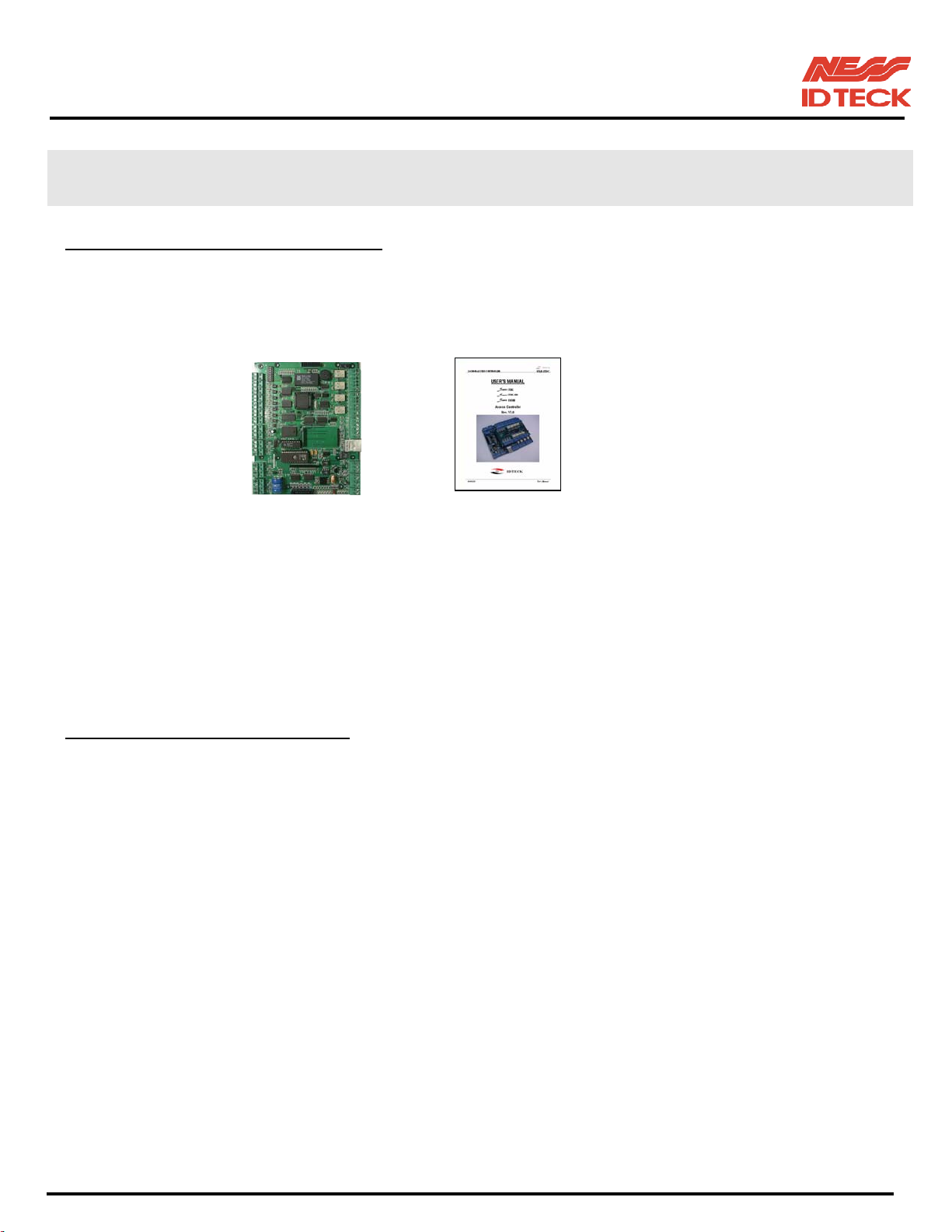
Please unpack and check the contents of the box. (Optional accessories, if purchased, may be included in
the package)
Main Unit Manual
(1) (1)
* Optional Accessories
EIO88 (Expansion I/O Board) – (Ness part No. 101-002)
Keypad (16 keys), LCD Display Module – (Ness part No. 101-003)
TCP/IP Module (IGM7100A) – (Ness part No. 101-124)
2.2 ABOUT NESS - IDTECK iTDC
The NESS - IDTECK iTDC is an intelligent 2~4 Door Access Controller designed to meet the market
requirements for high security, convenience, and reliability. This user-friendly device allows you to
register up to 50,000 User ID numbers, and it can buffer up to 29,500 events in its memory. 4 reader ports
can be connected with Proximity Readers, Proximity + PIN Readers or biometric fingerprint (or face
recognition) readers. Each reader can have its own operation mode, ether RF only, RF + Password,
fingerprint, RF + fingerprint, RF + PIN + fingerprint. Independent 7 input ports can be connected with
various devices such as Exit Buttons, Door Contact Sensors, PIR Sensors, Window Breakage Sensors and
Fire Sensors to strengthen security. Input/Output ports can be expanded by adding an Expansion I/O
Board. Optional Keypad and LCD Display module can be used to set-up functions manually and
programming inputs and outputs. Using RS232 or RS422 communication, a network system can be set up,
consolidating up to 256 units. All setting values including ID numbers, Inputs/Outputs, Real Time Clock,
Time Schedules and all Event Transaction Reports can be downloaded/uploaded from/to the host
computer with software supporting a variety of reporting formats. NESS - IDTECK iTDC can be installed
and managed inside the security zone for higher security. Experience the ultimate high-level security
access control system with NESS - IDTECK iTDC.
101-001 (iTDC), 101-002 (EIO88), 101-145 (iTDCSR) -5- Users Manual
Page 6

IDTeck – iTDC 2~4 DOOR ACCESS CONTROLLER
2.3 SPECIFICATION
CPU 8bit Microprocessor
Memory Program Memory: 64KB ROM
Power DC 12V/ 350mA max. (Excluding lock current)
Data Memory: 512KB RAM (battery backup)
Card Holders
/ Event Buffers
User Programmable by 1,000 unit of card holders
Card Holders: 1,000 ~ 50,000 users (Default: 5,000 users)
Event Buffers: 20,000 ~ 29,500 events (Default: 27,500 events)
Reader Ports 4 Reader Ports
Reader Data Format Standard 26 bits Wiegand Format,
Standard 34 bits Wiegand Format (Applied to iTDC-SR),
8 bits burst Format for keypad reader
Communication port RS232/RS422 (up to 256 channels) selectable
4800, 9600(Default), 19200, 38400bps communication speed
Inputs/Outputs
7 Input ports/ DC12V/ 20mA
4 Relay Output ports/ DC12V~24V/ FORM-C Relay 2A max.
3 TTL Output ports: DC5V/ 20mA
Optional EIO88 Expansion I/O board (8 Inputs and 8 Output Relays)
Self Diagnostic Yes
Reset Power on reset and Watchdog timer reset
Operation Status 21 LED (red or green) indicators
Operating Environment
0°C ~ +65°C, 0 ~ 90%(Humidity)
Weight 250g (0.55 lbs)
Dimensions 185mm x145mm x 18mm (7.4” x 5.8” x 0.72”)
Optional
Keypad 16 keys
LCD Display Module 2Lines x 16ch, 2.62” x 0.55”(65.6mm x 13.8mm) viewing area
Expansion I/O Board EIO88 (8 Input ports/8 Output Relays)
***Required to control doors 3 & 4)***
TCP/IP module IIM7100A
101-001 (iTDC), 101-002 (EIO88), 101-145 (iTDCSR) -6- Users Manual
Page 7

IDTeck – iTDC 2~4 DOOR ACCESS CONTROLLER
3. PRODUCT OVERVIEW
3.1 FUNCTIONS
Stand-Alone Operation
The NESS - IDTECK iTDC is capable of having 4 readers (4 Door Controls – NOTE : EIO88 is required
to control doors 3 & 4). The unit receives card ID numbers from the proximity readers and determines
whether or not to unlock the door. When an input signal is entered, for example from a sensor activated or
an exit button pressed, the controller generates and logs an appropriate response by input signals. All
events are stored into the memory buffers and sent to the host computer. The access controller is a true
stand-alone device that, in the event of malfunction, will not affect to other units when used in conjunction
with one another.
Operation with Host Computer
All event transactions can be managed via the host computer. The data transmitted from the controller can
be displayed and stored on the host PC.
Data Backup
The controller retains all user information and event data for 30 days, even in the event of power failure.
CAUTION: Battery Jumper must be set correctly before the unit running.
(See the INSTALLATION section)
Keypad
If the NESS - IDTECK iTDC is not connected to host PC, the integrated keypad and LCD display module
can also be used for programming process manually.
Anti-Pass-Back
Using an additional proximity reader for exiting, the Anti-Pass-Back mode can be set. Anti-pass-back
mode prevents any entry or exit when the registered user did not properly followed one entry and one exit
by the Anti-pass-back rule. APB only allowed exit for the user once got into the door first and it doesn’t
allow any user trying twice entry or twice exit.
101-001 (iTDC), 101-002 (EIO88), 101-145 (iTDCSR) -7- Users Manual
Page 8

IDTeck – iTDC 2~4 DOOR ACCESS CONTROLLER
Number of Door Control (2/3/4 Door Control)
The iTDC controller can control up to 4 doors with 4 readers. If controlling 2 doors, APB can be applied
to both doors. If controlling 3 doors, APB can only be applied to first door using reader 1 for entry and
reader 2 for exit. Door 2 and 3 cannot use APB function as there is only entry reader installed. If
controlling 4 doors, APB function cannot be used. (If controlling 3 and 4 doors, you must use optional
Expansion I/O board (EIO88 – Ness part No 101-003) to install Exit Button, Door Contact Sensor, Door
Relays and Alarm devices)
Input/Output
The NESS - IDTECK iTDC has built-in 7 inputs and 7 outputs (4 relay outputs and 3 TTL outputs), which
can be used to manipulate a wide variety of controls.
Optional Expansion I/O
Optional Expansion I/O board (EIO88, (Ness part No. 101-003) additional 8 inputs and 8 output relays)
can be connected to the iTDC controller. It can control additional inputs and outputs from iTDC main
controller.
Input Device Type Set-up (NO, NC)
If the input device is normal open (NO) type sensor, you have to set-up the input device type to (NO).
This gives the iTDC will activate when the input port makes short circuit to ground. If the input device is
normal close (NC) type sensor, you have to set-up the input device type to (NC). This gives the iTDC will
activate when the input port makes open circuit. All input device type can be programmed by software
program on the host computer. (This set-up is also applied to optional Expansion I/O board)
Time schedule Set-up
You can program 15 time schedules and apply one time schedule to each user. Each time schedule has 8
different time zones from Monday to Sunday (7 time zones) and one holiday. Each time zone has 5
different time codes so you can program 5 different time codes to each day. The software program on the
host computer can program all time schedules. Also you can program time schedule for individual inputs
and outputs.
Note each input (or output) can have a time schedule assigned to it. In this case the input will only be
active during this time schedule and the output can also active automatically during a time schedule. Each
time schedule is also linked to one of the holiday schedules.
Holiday Schedule Set-up
Excepting Sunday, you can program 100 holidays to one holiday schedule. Each holiday schedule is
linked to one time schedule, which has time code for holidays. So you can program all holidays to holiday
schedule and the time code for holidays is programmed to holiday time zone of time schedule.
Example: A. Holiday schedule 01 linked to time schedule 01,
Holiday schedule 02 linked to time schedule 02
B. Holiday schedule 02 linked to time schedule 01,
Holiday schedule 01 linked to time schedule 03
Forced Door Open Alarm
101-001 (iTDC), 101-002 (EIO88), 101-145 (iTDCSR) -8- Users Manual
Page 9
IDTeck – iTDC 2~4 DOOR ACCESS CONTROLLER
When door is opened by force, the door contact sensor is activated then forced door open alarm will be
generated until the door is closed. For this application, you have to install door contact sensor (Reed
Switch) to the door and you have to properly set door contact time and outputs to alarm devices.
Duress Alarm / Alarm Arm – Disarm Code
In case of duress, (or External Alarm Arm - Disarm) enter the 2 digits Duress Password and <ENT> key
before the normal access process. The door will be opened as normal but the duress alarm is also
generated at the same time and the duress alarm output will be activated to TTL output and alarm event
will be sent to the host PC.
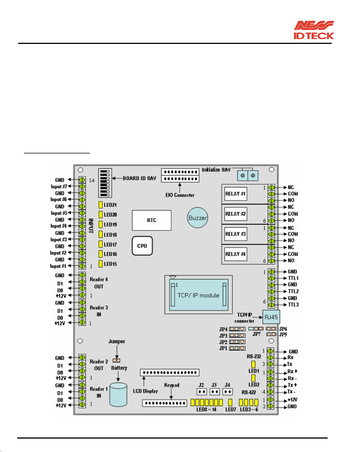
3.2 BOARD LAYOUT
Figure: iTDC Control Board Layout
101-001 (iTDC), 101-002 (EIO88), 101-145 (iTDCSR) -9- Users Manual
Page 10

IDTeck – iTDC 2~4 DOOR ACCESS CONTROLLER
BOARD ID S/W
This BOARD ID S/W is for communication ID setting of iTDC control board.
EIO Connector
This EIO Connector is the port for connecting the optional EIO88 expansion I/O board.
Initialise S/W
This Initialise S/W is to initialise and erase all user data from the memory. There are two tactile switches
and the initialisation is only active when the two tactile switches are pressed.
Relay #1 ~ Relay #4
These are 4 FORM-C (COM, NO, NC) relay outputs at DC12~24V, Max. 2A current.
TTL #1 ~ TTL #3
These are 3 TTL output ports at DC5V TTL level, max. 20mA current.
The normal logical state of TTL output is Low (DC0V) and activates to High (DC5V).
TCP/IP connector
This is RJ45 connector for TCP/IP communication port and you can use this TCP/IP port when you install
the optional TCP/IP module on the board.
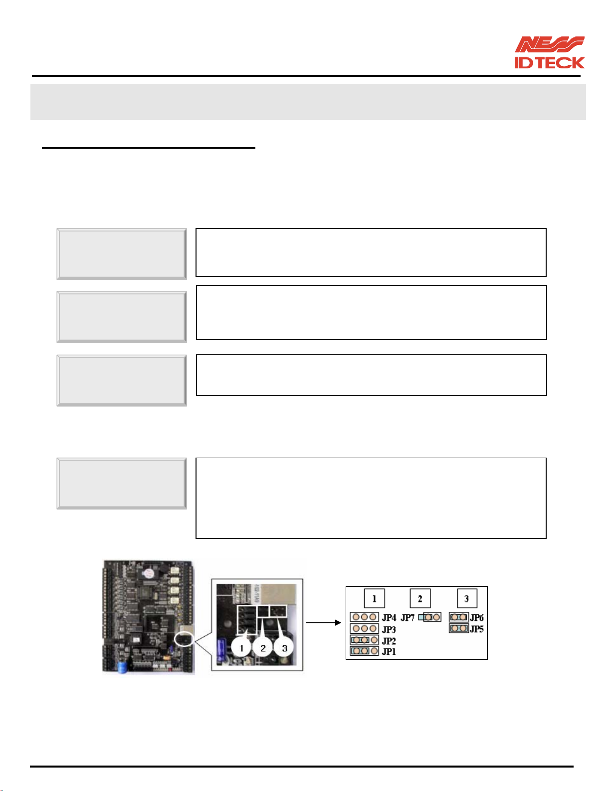
Jumper Switch for TCP/IP, RS422 Communication (JP1 ~ JP4):
This is Jumper switch for TCP/IP or RS 422 communication selection
The Figure (
Jumper Switch for RS_422 Communication test (JP5~6):
This is jumper switch for RS_422 communication test.
This test is RS422 port by communication test of [SETUP F4].
Extract jumper of JP3~4 and shorts JP5~6 by this jumper.
Initial status of JP5~6 is Open.
Jumper Switch for TCP/IP module selection (JP7):
This is jumper switch for selection TCP/IP internal module (IIM7100 or IIM7100A).
The Figure (iTDC Control Board Layout) is initial status. (Default: IIM7100A)
iTDC Control Board Layout) is initial status. (Default: RS422 communication)
RS-232 Serial Communication Port
This is RS232 communication port for connecting this board directly to PC.
RS-422 Serial Communication Port
This is RS422 communication port for connecting multiple boards up to 256 units to PC.
You need RS422/RS232 converter for connecting RS422 port to PC.
+12V and GND (Main Power)
This is main power connection of control board and iTDC is working at DC12V, max. 250mA current.
Keypad
This is optional keypad port and it can be used with optional LCD display module for manual set-up.
101-001 (iTDC), 101-002 (EIO88), 101-145 (iTDCSR) -10- Users Manual
Page 11

IDTeck – iTDC 2~4 DOOR ACCESS CONTROLLER
LCD Display
This is optional LCD Display port and it can be used with optional keypad for manual set-up.
Jumper
This is Battery Connection Jumper and you have to make short circuit of this jumper before you use iTDC
control board, as this jumper is the connection of backup battery to the internal memory devices.
Reader #1 ~ Reader #4
These are 4 proximity reader ports and each reader port supplies DC12V to the proximity reader and
receives 26bit Wiegand output from the reader. If you connect PINPAD Reader then you have to make
sure that the PINPAD Reader has 8bit burst output through Wiegand output.
Input #1 ~ Input #7
These are 7 Input Ports.
Buzzer
This is internal Buzzer and it makes beep sounds when you press the keypad from the optional keypad so
you can confirm how many keys are pressed
TCP/IP Module
This is the location for the optional TCP/IP module (IIM7100A – Ness part No. 101-124) and you have to
install TCP/IP module at this location when you want to use TCP/IP communication port.
LED1 ~ LED2
These 2 LEDs indicate the communication status. LED1 is RX status and it blinks when the data is
receiving from the PC. LED2 is TX status and it blinks when the data is transmitting to the PC
LED3 ~ LED6
These 4 LEDs indicate communication status of TCP/IP module. LED3 is Connection Status, LED4 is
10Mbps, LED5 is 100Mbps and LED6 is Collision Status indicator.
LED7
This red colour LED is power indicator and it always on when the control board powered on.
LED8 ~ LED14
These 7 LEDs indicate output status. Each LED is on when the corresponding output is activated, LED8 is
for Relay #1, LED9 is for Relay #2, LED10 is for Relay #3, LED11 is for Relay #4, LED12 is for TTL 1,
LED13 is for TTL 2 and LED14 is for TTL 3 output.
LED15 ~ LED21
These 7 LEDs indicate input status. Each LED is on when the corresponding input is activated (short
circuit to ground), LED15 is for Input 1, LED16 is for Input 2, LED17 is for Input3, LED18 is for Input 4,
LED19 is for Input 5, LED20 is for Input 6 and LED21 is for Input 7.
101-001 (iTDC), 101-002 (EIO88), 101-145 (iTDCSR) -11- Users Manual
Page 12
IDTeck – iTDC 2~4 DOOR ACCESS CONTROLLER
3.3 OPTIONAL ACCESSORIES
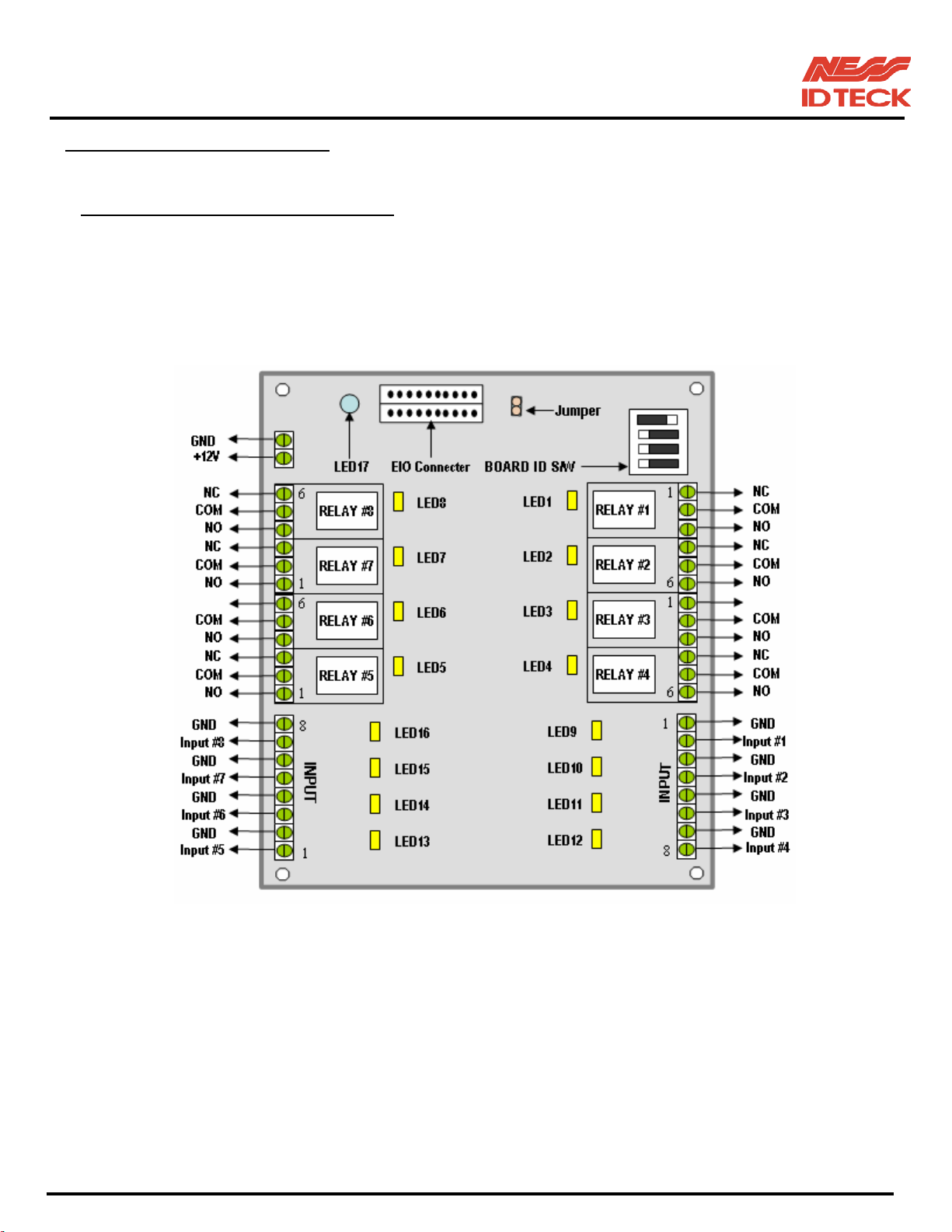
3.3.1 EIO88 EXPANSION I/O BOARD
(Ness Part No. 101-002)
The EIO88 board features:
- 8 Inputs ports
- 8 FORM-C Relay Output ports
- 4 Inputs can be configured to Door 3 ~ 4 as of exit buttons and door contact sensors.
- 4 Output Relays can be configured to Door 3 ~ 4 as of door locks and alarm devices.
Figure: EIO88 Expansion I/O Board Layout
EIO connector
This EIO Connector is the port for connecting to iTDC Main Control board.
BOARD ID S/W
The DIPswitch is factory set as shown on the above layout. DO NOT change the setting as
it may cause wrong operation of EIO88 expansion I/O board.
+12V and GND (Main Power)
This is main power connection of expansion I/O board working at DC12V, max. 100mA current.
101-001 (iTDC), 101-002 (EIO88), 101-145 (iTDCSR) -12- Users Manual
Page 13

IDTeck – iTDC 2~4 DOOR ACCESS CONTROLLER
Relay #1 ~ Relay #8
These are 8 FORM-C (COM, NO, NC) relay outputs at DC12~24V, max. 2A current.
Input #1 ~ Input #8
These are 8 Input Ports.
LED17
This red colour LED is power indicator and it always on when the EIO88 board powered on.
LED1 ~ LED8
These 8 LEDs indicate output status. Each LED is on when the corresponding output is activated.
LED1: Relay #1, LED2: Relay #2, LED3: Relay #3, LED4: Relay #4,
LED5: Relay #5, LED6: Relay #6, LED7: Relay #7, LED8: Relay #8
LED9 ~ LED16
These 7 LEDs indicate input status. Each LED is on when the corresponding input is activated.
LED9: Input #1, LED10: Input #2, LED11: Input #3, LED12: Input #4,
LED13: Input #5, LED14: Input #6, LED15: Input #7, LED16: Input #8
3.3.2 TCP/IP MODULE
You can add optional TCP/IP module (IIM7100A) and this module can be used if you want
TCP/IP communication to the host PC.
3.3.3 LCD DISPLAY MODULE
You can connect optional LCD display module to iTDC main control board and you can
use LCD display module with optional keypad when you set-up all functions to iTDC
manually.
3.3.4 KEYPAD
You can connect optional Keypad to iTDC main control board and you can use keypad
with LCD display module when you set-up all functions to iTDC manually.
101-001 (iTDC), 101-002 (EIO88), 101-145 (iTDCSR) -13- Users Manual
Page 14
IDTeck – iTDC 2~4 DOOR ACCESS CONTROLLER
4. INSTALLATION TIPS & CHECK POINT
Installing the iTDC is a relatively easy task. It can be installed with common hand tools and readily available
communications wire. This section provides information about wiring, wire runs and other information to make
the installation quick and easy.
4.1 CHECK POINTS BEFORE INSTALLATION
4.1.1 SELECTION OF CABLE
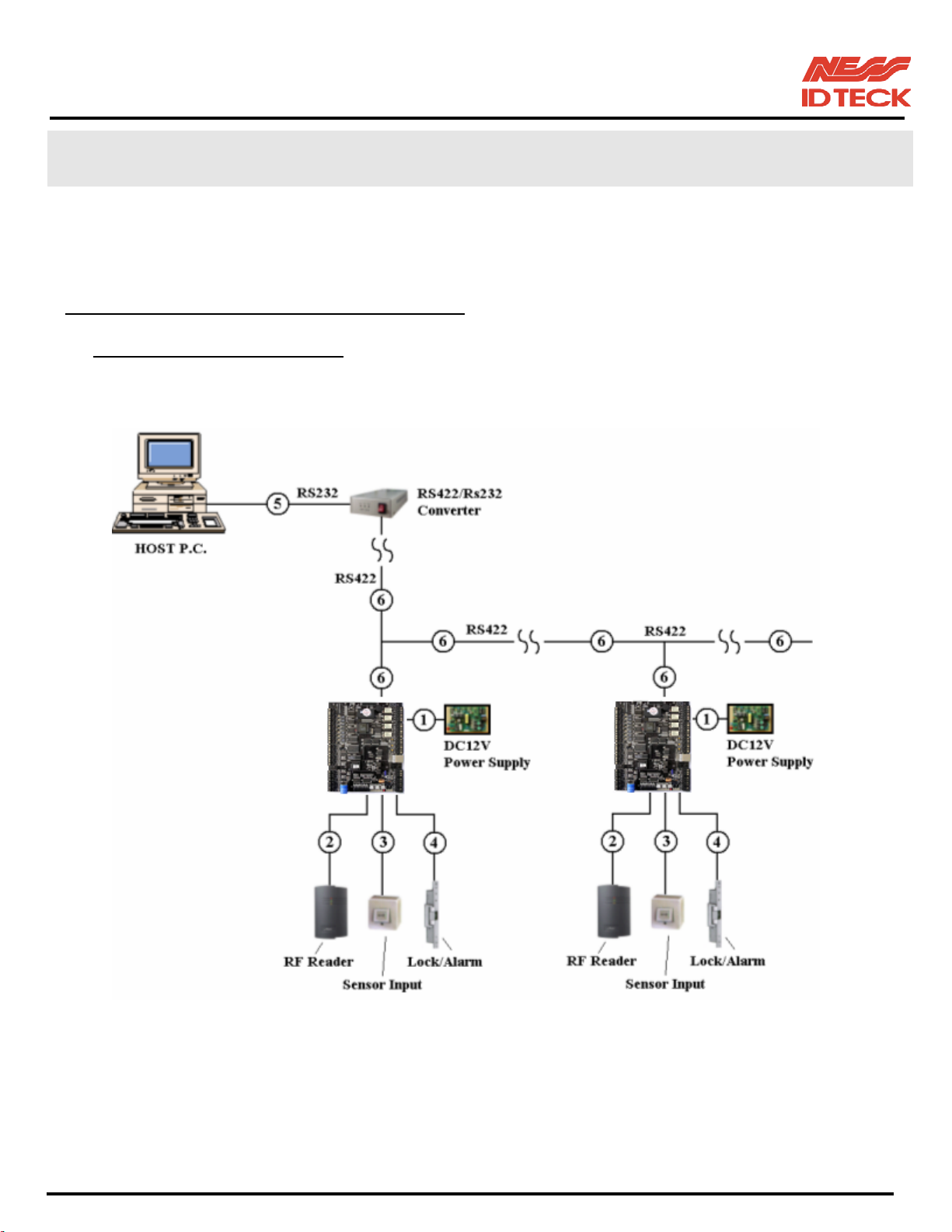
System installation cabling will be configured as follow.
Figure: System Installation Layout
101-001 (iTDC), 101-002 (EIO88), 101-145 (iTDCSR) -14- Users Manual
Page 15

IDTeck – iTDC 2~4 DOOR ACCESS CONTROLLER
4.1.2 RECOMMENDED CABLE TYPE AND PERMISSIBLE LENGTH OF CABLE
Reference Description Cable Specification
Maximum
Distance
iTDC Power (DC12V)
Belden #9409, 18 AWG
①
DC Power -> iTDC
2 conductor, unshielded
Belden #9512, 22 AWG
Reader (Power and Data)
4 conductor, shielded
②*
Extra Reader -> iTDC
Belden #9514, 22 AWG
8 conductor, shielded
Door Contact
Exit Button
Belden #9512, 22 AWG
4 conductor, shielded
③
Sensor Input
Input -> iTDC
Door Lock, Alarm Device
Belden #9514, 22 AWG
8 conductor, shielded
Belden #9409, 18AWG
④
Lock (Alarm) -> iTDC
RS232 Cable
2 conductor, unshielded
Belden #9829, 24 AWG
⑤
Converter -> Host P.C.
2-twisted pair, shielded
30m
150m
300m
300m
15m
RS485 Cable
Belden #9829, 24 AWG
iTDC -> iTDC
2-twisted pair, shielded
iTDC -> Converter
⑥
RS422 Cable
Belden #9830, 24 AWG
iTDC -> iTDC
3-twisted pair, shielded
iTDC -> Converter
*:
Need thicker wire if you connect the reader with high current consumption.
4.2 CHECK POINT DURING INSTALLATION
4.2.1 TERMINATION RESISTOR
Termination resistors are used to match impedance of the network to the impedance of the transmission
line being used. When impedance is mismatched, the transmitted signal is not completely absorbed by the
receiver and a portion of signal is reflected back into the transmission line.
The decision whether or not to use termination resistors should be based on the cable length and data rate
used by the communication system.
1,200m
For example, if you use 9,600 baud rate and 1,200m length of cable, the propagation velocity of cable is
0.66 x speed of light (This value is specified by the cable manufacturer), if we assume the reflections will
damp out in three round trips up and down the cable length, the transmitted signal will stabilize 18.6us
101-001 (iTDC), 101-002 (EIO88), 101-145 (iTDCSR) -15- Users Manual
Page 16
IDTeck – iTDC 2~4 DOOR ACCESS CONTROLLER
after the leading edge of a bit. Since the data bit is captured in the middle of the bit, which is
approximately 52us after the leading edge of a bit. The reflection stabilizing time 18.6us is much before
the centre of the bit therefore the termination resistors are not required.
However, if you install the cable to maximum length, the impedance of cable and network is mismatched
and the transmitted signal is overlapped by the reflected signal. In this case, it is recommended to add
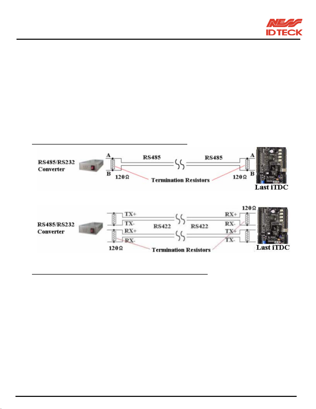
termination resistors to the end of the receiver lines. A 120Ω resistor can be used for termination resistor
in parallel between the receiver lines “A” and “B” for 2 wires RS485 system or “RX+” and “RX-” for 4
wires RS422 system. A termination resistor of less than 90Ω should not be used and no more than 2
terminations should be used in one networking system.
4.2.2 HOW TO CONNECT TERMINATION RESISTORS
Figure: Termination resistors for 2 wire RS485 communication system
Figure: Termination resistors for 4 wire RS422 communication system
4.2.3 GROUNDING SYSTEM FOR COMMUNICATION CABLE
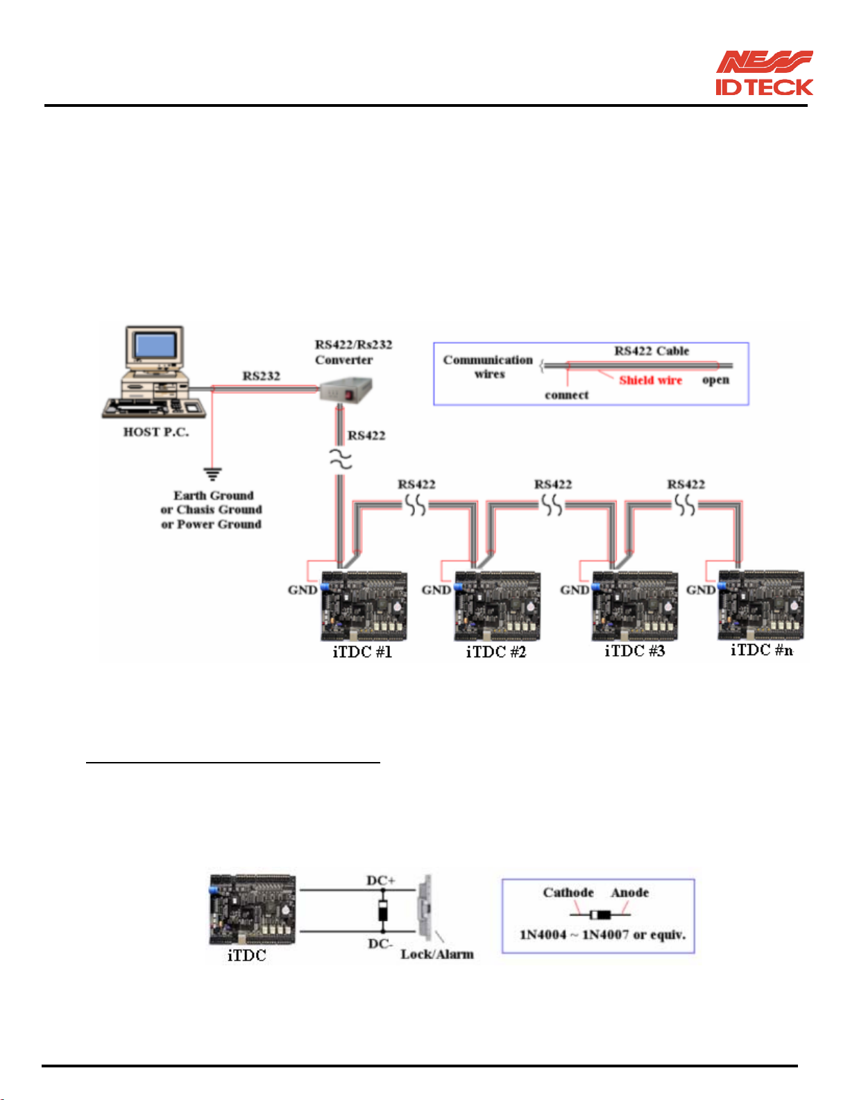
We recommend to using proper grounding system on the communication cable. The best method for
grounding system is to put the shield wire of the communication cable to the 1st class earth grounding;
however it is not so easy to bring the earth ground to the communication cable and also the installation
cost is raised.
There will be three grounding point where you can find during installation;
1) Earth Ground
2) Chassis Ground
3) Power Ground
The most important point for grounding system is not to connect both ends of shield wires to the
grounding system; in this case there will be a current flow through the shield wire when the voltage level
of both ends of shield wire is not equal and this current flow will create noise and interfere to
communications.
101-001 (iTDC), 101-002 (EIO88), 101-145 (iTDCSR) -16- Users Manual
Page 17
IDTeck – iTDC 2~4 DOOR ACCESS CONTROLLER
For the good grounding, we recommend to connecting ONLY one end of shield wire of communication
cable to grounding system; If you find earth ground nearby, then connect one end of shield wire to earth
ground; If you do not have earth ground nearby, then find chassis ground and connect one end of shield
wire to chassis ground; If you do not find both earth ground and chassis ground, then connect one end of
shield wire to power ground.
Note that if the chassis ground is not properly connected to the earth and floated from the ground level,
then grounding to the chassis ground will give communication problems; in this case we recommend to
use power ground instead of chassis ground.
Figure: Grounding system
4.2.4 REVERSE DIODE CONNECTION
If you connect an inductor (Door Locks or Alarm device) to the output relays, there will be a high surge
voltage created while the inductor is turning on and off. If you do not connect reverse diode, the surge
voltage will transfer and damage to the electronic circuit of the controller. It is strongly recommended to
add a reverse diode between the inductor coils to absorb this surge voltage.
Figure: Reverse Diode connection
101-001 (iTDC), 101-002 (EIO88), 101-145 (iTDCSR) -17- Users Manual
Page 18
IDTeck – iTDC 2~4 DOOR ACCESS CONTROLLER
5. INSTALLATION
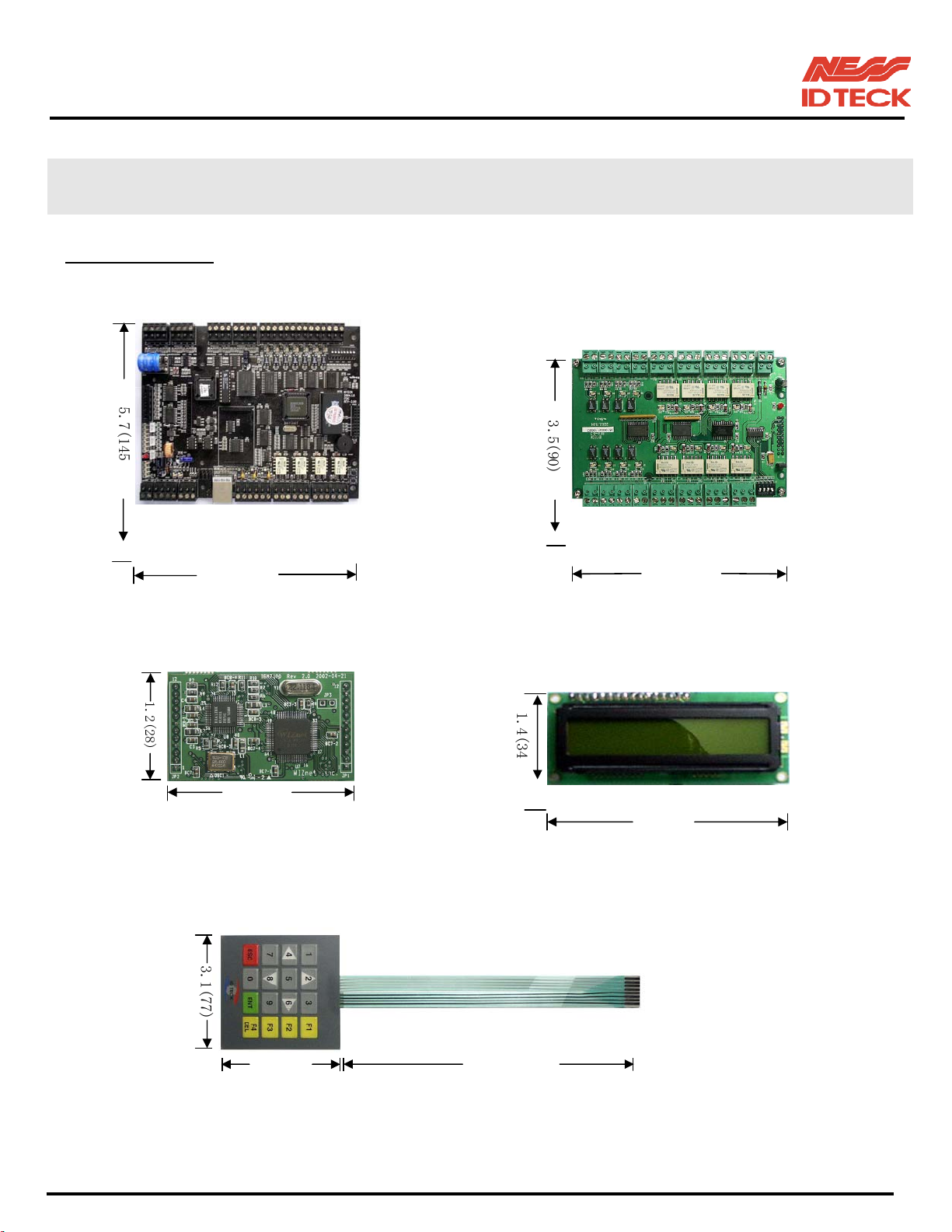
5.1 DIMENSIONS Unit: inch (mm)
5
.
7
(
1
4
5
3
.
5
(
9
0
)
7.3(185)
5.3(136)
iTDC DIMENSION EIO88 DIMENSION
1
.
2
(
2
8
)
1.9(47)
1
.
4
(
3
4
3.1(77)
TCP/IP MODULE DIMENSION LCD MODULE DIMENSION
3
.
1
(
7
7
)
3.1(77)
7.9(200)
KEYPAD DIMENSION
101-001 (iTDC), 101-002 (EIO88), 101-145 (iTDCSR) -18- Users Manual
Page 19
IDTeck – iTDC 2~4 DOOR ACCESS CONTROLLER
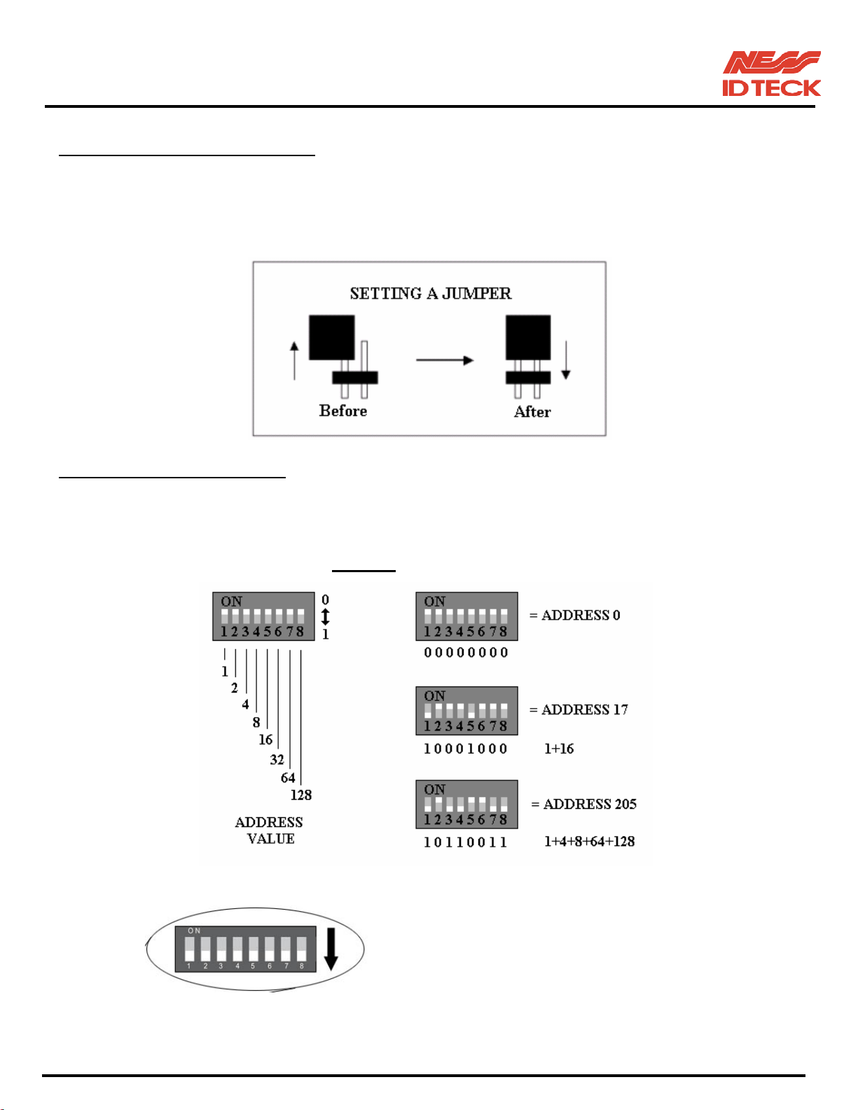
5.2 BACKUP BATTERY JUMPER
iTDC has a jumper for the backup battery connection, which is left open circuit to prevent any current
consumption of backup battery during storage and shipment. (Figure: Jumper setting). Before the iTDC
put into operation, it needs to be connected so that the backup battery can retain the memory during power
failure.
5.3 DIP SWITCH (BOARD ID)
There is 8bit DIP SW for address setting and it turns to 8bit binary code as below and each bit has fixed
Figure: JUMPER SETTING
Address value, the address is calculated the sum value of each bit set to “1” position.
Example
NOTE: To select the address switch
the address switch towards the left
side of the PCB.
101-001 (iTDC), 101-002 (EIO88), 101-145 (iTDCSR) -19- Users Manual
Page 20

IDTeck – iTDC 2~4 DOOR ACCESS CONTROLLER
5.4 WIRING
5.4.1 POWER
Connect (+) wire of DC 12V power to +12V terminal
Connect GND (-) wire of DC 12V power to GND terminal
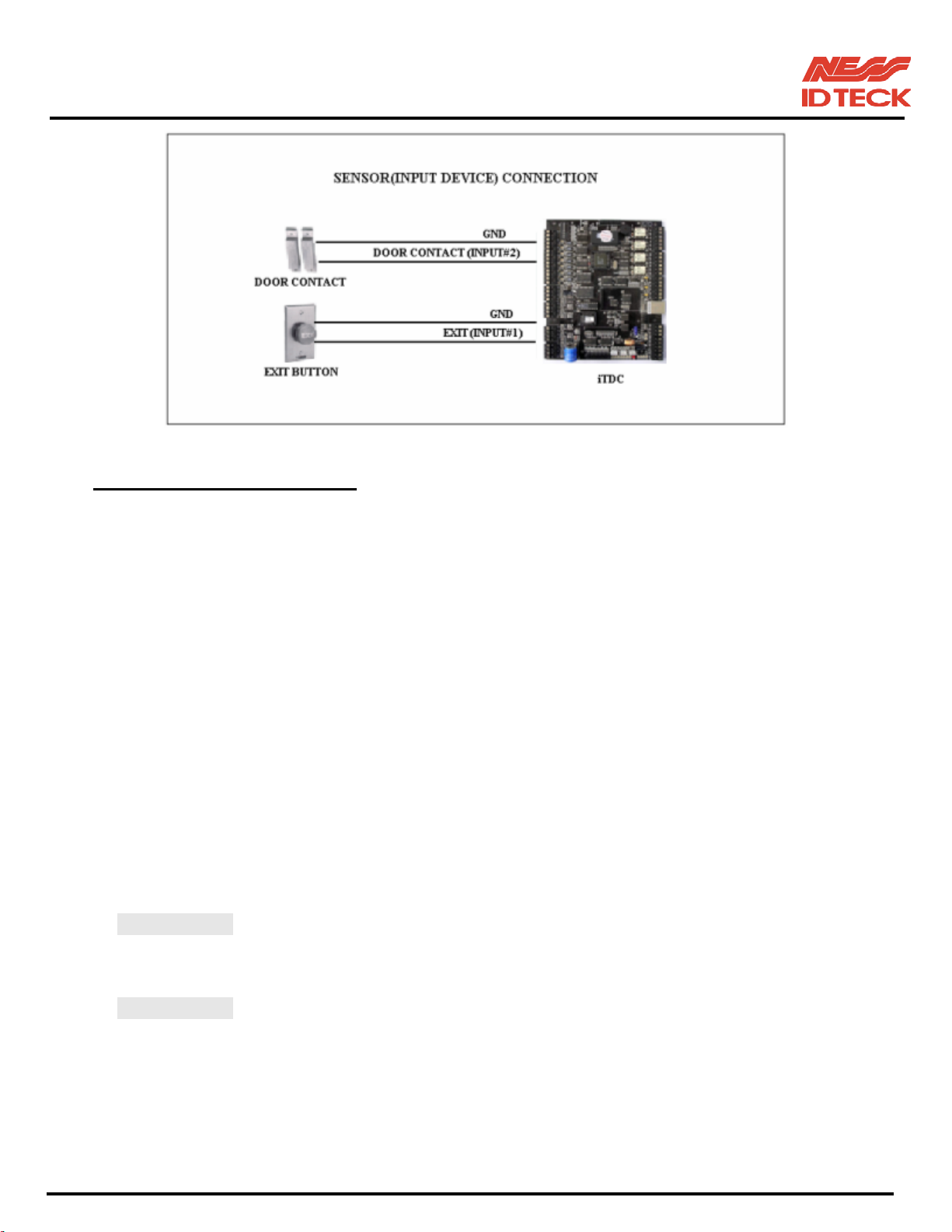
5.4.2 INPUT CONNECTIONS
Exit Button Connection (Input #1, Input #3)
- Connect one wire from an Exit Button to Input #1 for the Door1 and to Input #3 for Door2
- Connect the other wire from the Exit Button to the GND
Door Contact Sensor Connection (Input #2, Input #4)
- Connect one wire from a Door Contact Sensor to Input #2 for the Door1 and to Input #4 for Door2
- Connect the other wire from the Door Contact Sensor to GND
Summary of Input connections to corresponding Doors
2-Door Control Door1: Input #1 to Exit Button, Input #2 to Door Contact Sensor
Door2: Input #3 to Exit Button, Input #4 to Door Contact Sensor
3-Door Control Door1: Input #1 to Exit Button, Input #2 to Door Contact Sensor
Optional EIO88 Expansion I/O Board controls the Exit Button and
Door Contact Sensor for Door2 and Door3.
Door2: EIO88 Input #1 to Exit Button, EIO88 Input #2 to Door Contact
Door3: EIO88 Input #3 to Exit Button, EIO88 Input #4 to Door Contact
4 Door Control Door1: Input #1 to Exit Button, Input #2 to Door Contact Sensor
Door2: Input #3 to Exit Button, Input #4 to Door Contact Sensor
Optional EIO88 Expansion I/O Board controls the Exit Button and
Door Contact Sensor for Door3 and Door4.
Door3: EIO88 Input #1 to Exit Button, EIO88 Input #2 to Door Contact
Door4: EIO88 Input #3 to Exit Button, EIO88 Input #4 to Door Contact
Auxiliary Input Connection (Applied to Input #5, Input #6 and Input #7)
- Connect one wire from an Auxiliary Input Device to one of the Input #5, #6 and #7.
- Connect the other wire from the Auxiliary Input Device to GND
Note: If you have EIO88 Expansion I/O Board, you can use EIO88 Input #5, Input #6,
Input #7 and Input #8 for additional auxiliary input devices.
101-001 (iTDC), 101-002 (EIO88), 101-145 (iTDCSR) -20- Users Manual
Page 21
IDTeck – iTDC 2~4 DOOR ACCESS CONTROLLER
Figure: INPUT DEVICES CONNECTION
5.4.3 OUTPUT CONNECTIONS
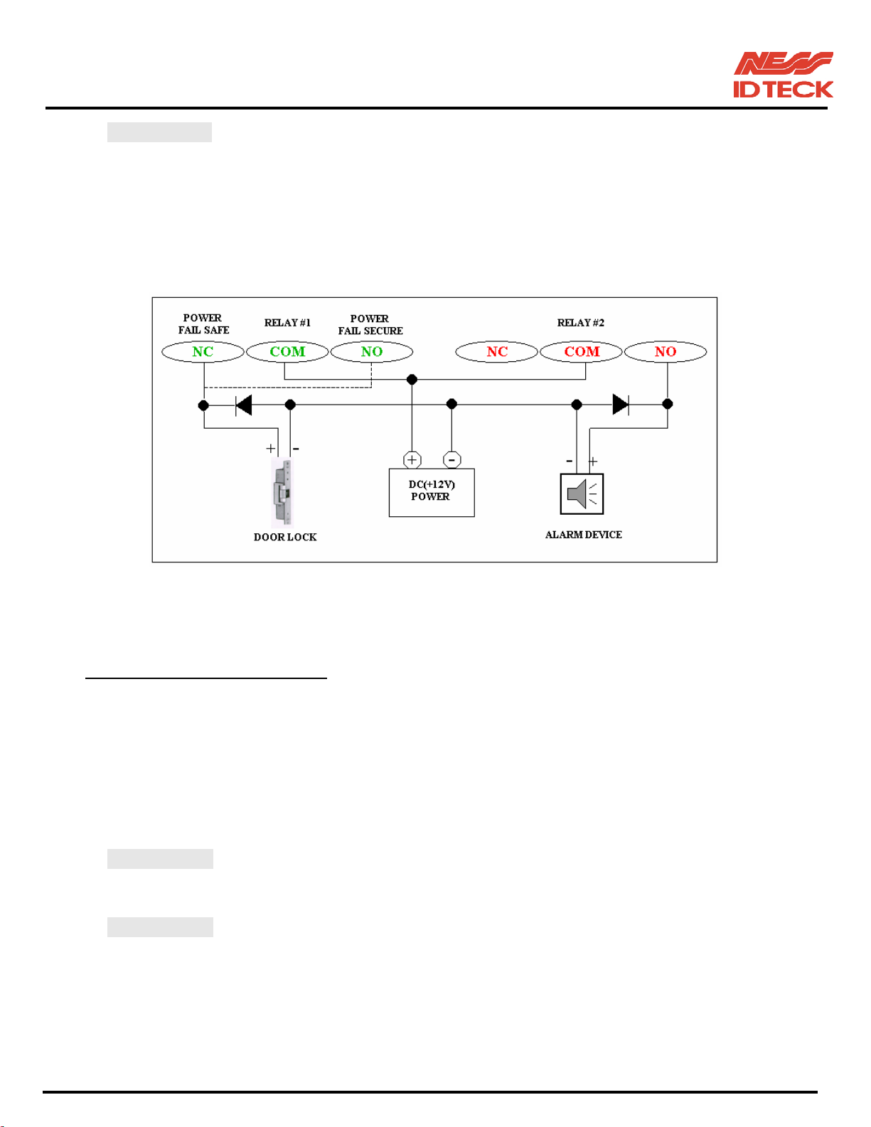
Door Lock (Power Fail Safe) Connection (Door1: Relay #1, Door2: Relay #3)
- Connect COM port of Relay #1 and Relay #3 to +12V
- Connect NC port of Relay #1(Door1) and Relay #3 (Door2) to (+) wire of door lock device
- Connect GND port to (-) wire of door lock devices
Door Lock (Power Fail Secure) Connection (Door1: Relay #1, Door2: Relay #3)
- Connect COM port of Relay #1 and Relay #3 to +12V
- Connect NO port of Relay #1(Door1) and Relay #3 (Door2) to (+) wire of door lock device
- Connect GND port to (-) wire of door lock devices
Alarm Device Connection (Door1 Alarm: Relay #2, Door2 Alarm: Relay #4)
- Connect COM port of Relay #2 and Relay #4 to +12V
- Connect NO port of Relay #2(Door1) and Relay #4 (Door2) to (+) wire of Alarm devices
- Connect GND port to (-) wire of Alarm devices
Summary of Output Relay connections to corresponding Doors
2-Door Control Door1: Relay #1 to Door Lock, Relay #2 to Alarm Device
Door2: Relay #3 to Door Lock, Relay #4 to Alarm Device
3-Door Control Door1: Relay #1 to Door Lock, Relay #2 to Alarm Device
Optional EIO88 Expansion I/O Board controls the Door Lock and
Alarm Devices for Door2 and Door3.
Door2: EIO88 Relay #1 to Door Lock, EIO88 Relay #2 to Alarm
Door3: EIO88 Relay #3 to Door Lock, EIO88 Relay #4 to Alarm
101-001 (iTDC), 101-002 (EIO88), 101-145 (iTDCSR) -21- Users Manual
Page 22
IDTeck – iTDC 2~4 DOOR ACCESS CONTROLLER
4 Door Control Door1: Relay #1 to Door Lock, Relay #2 to Alarm Device
Door2: Relay #3 to Door Lock, Relay #4 to Alarm Device
Optional EIO88 Expansion I/O Board controls the Door Lock and
Alarm Devices for Door3 and Door4.
Door3: EIO88 Relay #1 to Door Lock, EIO88 Relay #2 to Alarm
Door4: EIO88 Relay #3 to Door Lock, EIO88 Relay #4 to Alarm
Figure: DOOR LOCK, ALARM DEVICE CONNECTION
NOTE: Add DIODES as shown above.
DIODE: Fast recovery DIODE (current: Min. 1A), 1N4001 ~ 1N4007 or similar
5.4.4 READER CONNECTIONS
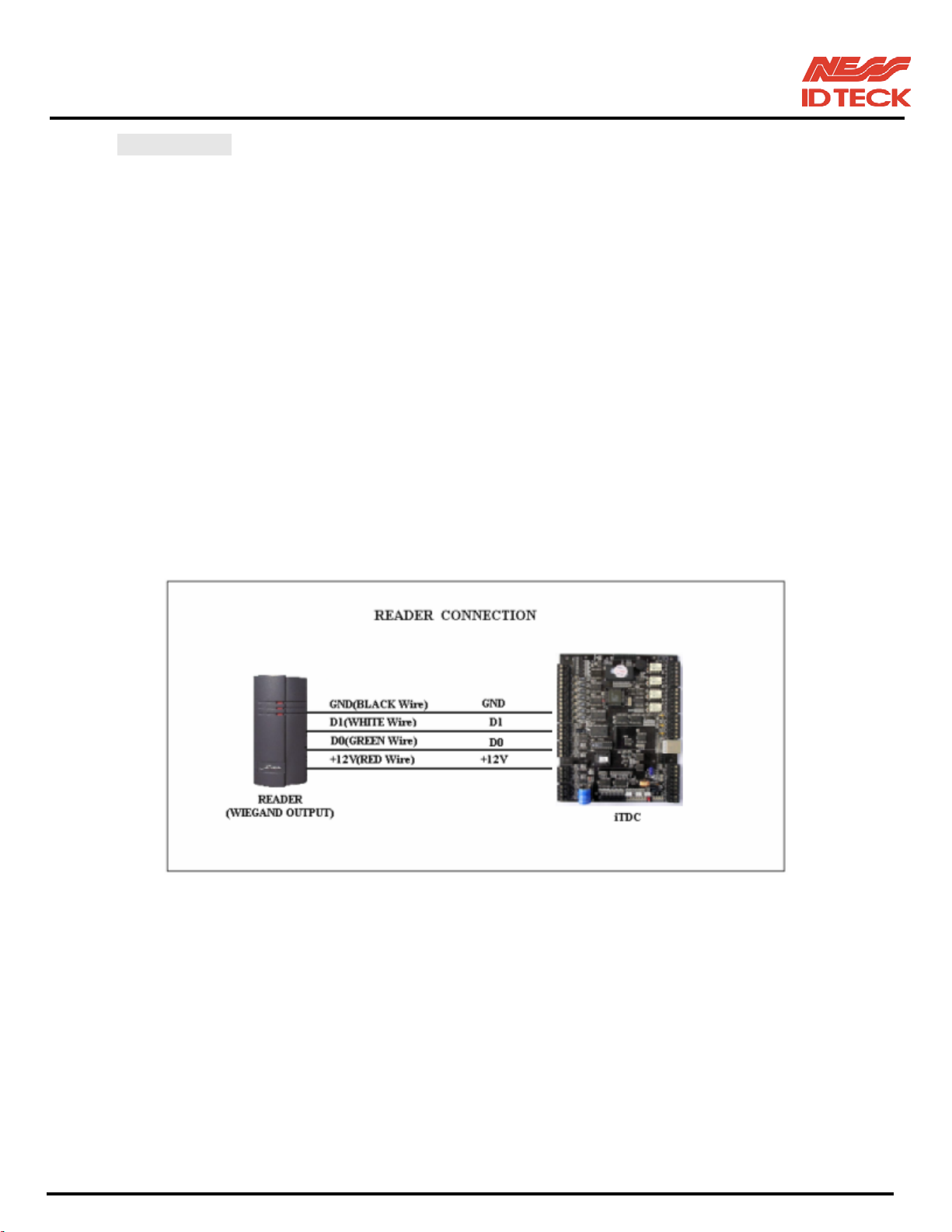
Proximity Reader Connection
- Connect (+) wire of the Proximity Reader to +12V of Reader port
- Connect (-) wire of the Proximity Reader to GND of Reader port
- Connect Data-0 wire of the Proximity Reader to D0 of Reader Port
- Connect Data-1 wire of the Proximity Reader to D1 of Reader Port
Summary of Proximity Reader locations to corresponding Doors
2-Door Control Door1: Reader #1 to Door1 Entrance, Reader #2 to Door1 Exit
Door2: Reader #3 to Door2 Entrance, Reader #4 to Door2 Exit
3-Door Control Door1: Reader #1 to Door1 Entrance, Reader #2 to Door1 Exit
Door2: Reader #3 to Door2 Entrance, Exit Button to Door2 Exit
Door3: Reader #4 to Door3 Entrance, Exit Button to Door3 Exit
You need optional EIO88 Expansion I/O Board to control Door Locks
and Exit Buttons for Door2 and Door3.
101-001 (iTDC), 101-002 (EIO88), 101-145 (iTDCSR) -22- Users Manual
Page 23
IDTeck – iTDC 2~4 DOOR ACCESS CONTROLLER
4 Door Control Door1: Reader #1 to Door1 Entrance, Exit Button to Door1 Exit
Door2: Reader #2 to Door2 Entrance, Exit Button to Door2 Exit
Door2: Reader #3 to Door3 Entrance, Exit Button to Door3 Exit
Door3: Reader #4 to Door4 Entrance, Exit Button to Door4 Exit
You need optional EIO88 Expansion I/O Board to control Door Locks
and Exit Buttons for Door3 and Door4.
z Compatible Readers:
iTDC: Standard 26bit Wiegand Format Proximity Readers
Standard 26bit Wiegand + 8bit Burst Format Proximity and Keypad Readers.
iTDC-SR: Standard 34bit Wiegand Format Proximity Readers
Standard 34bit Wiegand + 8bit Burst Format Proximity and Keypad Readers.
z Recommended Readers:
For iTDC: RF10, RF20, RF30, RF70, RF500, iPASS10, iPASS20, RFK101
For iTDC-SR: SR10, SR101
Figure: READER CONNECTION
101-001 (iTDC), 101-002 (EIO88), 101-145 (iTDCSR) -23- Users Manual
Page 24
IDTeck – iTDC 2~4 DOOR ACCESS CONTROLLER
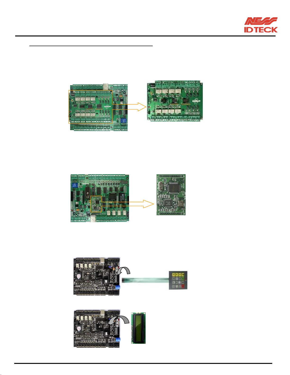
5.4.5 OPTIONAL ACCESSORY CONNECTIONS
Expansion I/O Board connection (EIO88)
- Connect the EIO88 Expansion I/O Board to iTDC as shown on below.
TCP/IP Module Connection (IIM7100A)
- Connect the IIM7100A TCP/IP Module as shown on below.
EIO88
(EXPANSION I/O BOARD)
TCP/IP module
Keypad and LCD Display Connection
- Connect the Keypad and LCD Display to the Keypad and LCD ports as shown on below.
Keypad
LCD
101-001 (iTDC), 101-002 (EIO88), 101-145 (iTDCSR) -24- Users Manual
Page 25
IDTeck – iTDC 2~4 DOOR ACCESS CONTROLLER
6. COMMUNICATIONS
6.1 Communication Port Test (Loop Test)
This is Loop test for communication test of [SETUP F4] (self-diagnosis functions).
You can check for communication state between iTDC and Cable.
6.1.1 RS232 Port Test
COMM TEST
TX data = 0
COMM test pass!!
6.1.2 RS422 Port Test
COMM TEST
☞. Before this communication test,
Connect the RS232-RX and RS232-TX wires together.
☞. This test is a loop test and iTDC sends a character to TX port and
check whether the RX port receive the character or not. If you
have an error, please contact our service facility.
☞. After the test is done, LCD will display “COMM test pass!!”.
Press any key to return to the set-upmenu.
☞. Before this communication test,
Connect the Rx (-) and TX (-), Rx (+) and TX (+) wires.
Note!! In case of RS-422 test, JP3, 4 disconnection and JP5, 6 short
After the test is done, short pin1, 2(or 2,3) of the JP3, 4.
Figure: Jumper switch location and Jumper switch setting for RS_422 communication test
101-001 (iTDC), 101-002 (EIO88), 101-145 (iTDCSR) -25- Users Manual
Page 26
IDTeck – iTDC 2~4 DOOR ACCESS CONTROLLER
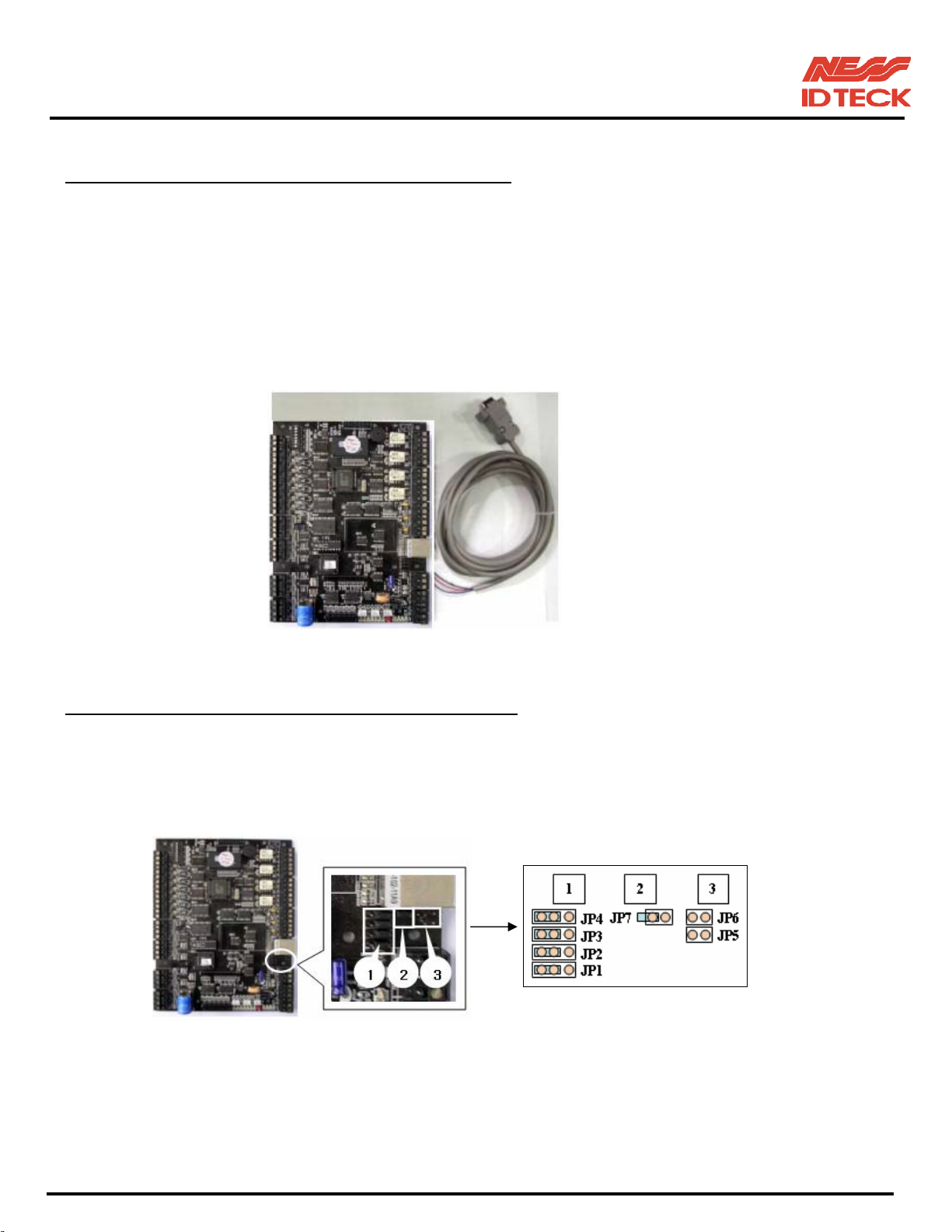
6.2 RS232 COMMUNICATION PORT CONNECTION
A 9-pin connector (Serial communication connector, female) is required to connect the iTDC to a host
computer via RS232 communication. Please follow the instructions.
- Connect RS232-TX port of iTDC to the pin #2 of the 9-pin connector.
- Connect RS232-RX port of iTDC to the pin #3 of the 9-pin connector.
- Connect RS232-GND of iTDC to the pin #5 of the 9-pin connector.
- Plug in the 9-pin connector to COM1 or COM2 Port of the host PC.
- Install and run iTDC Application Software.
Figure: RS-232 COMMUNICATON
6.3 RS-422 COMMUNICATION PORT CONNECTION
6.3.1 Jumper Switch Setting
Before the RS422 Communication, the jumper switch needs to be setting with the figure of the
below.
Figure: Jumper Switch location and setting for RS_422 communication
101-001 (iTDC), 101-002 (EIO88), 101-145 (iTDCSR) -26- Users Manual
Page 27
IDTeck – iTDC 2~4 DOOR ACCESS CONTROLLER
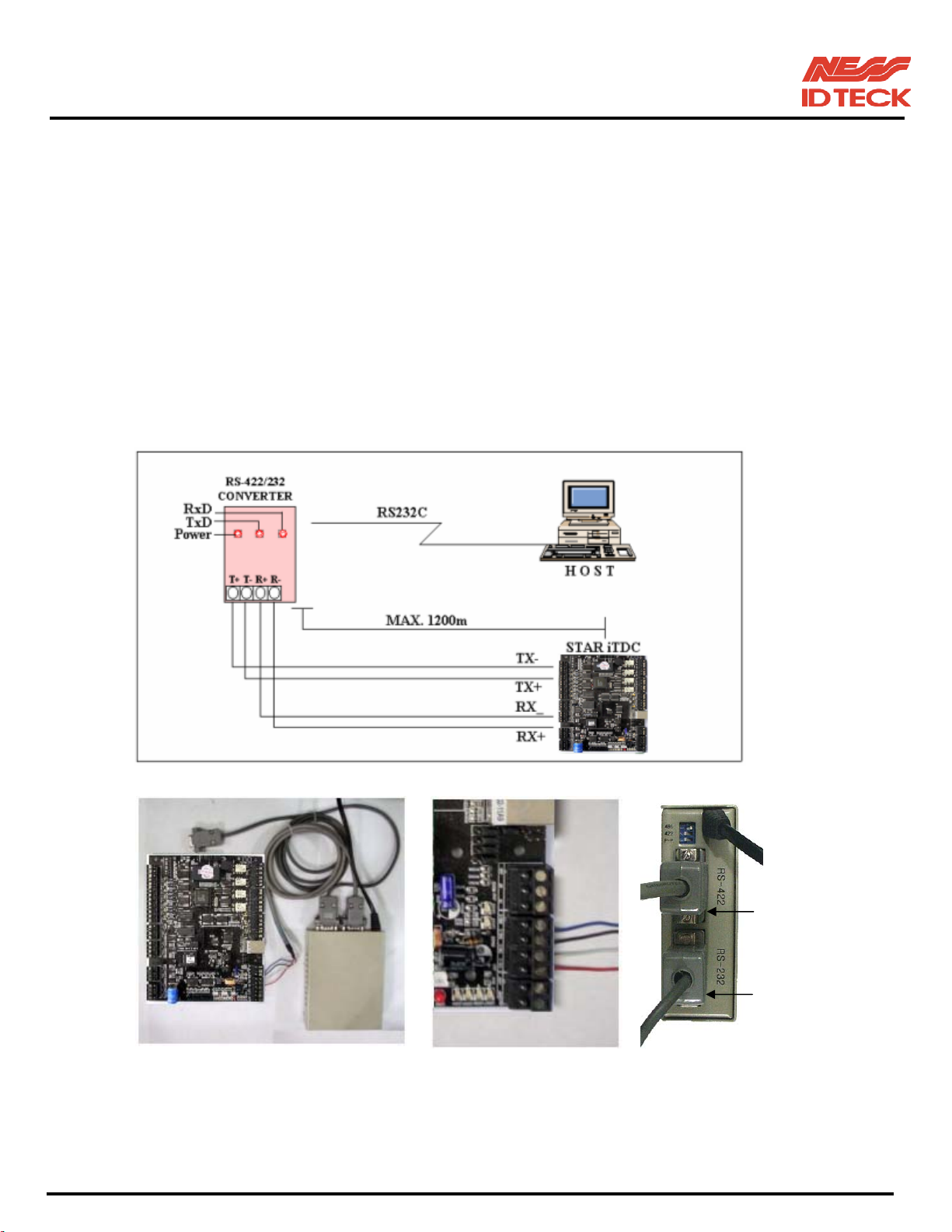
6.3.2 RS-422 CONNECTION (STAND ALONE)
RS422/RS232 converter (CNP200) is required to use RS422 communication between the iTDC and a host
computer. Please follow the instructions.
- Connect RS422-TX (+) of the iTDC to RS422-RX (+) port of the converter.
- Connect RS422-TX (-) of the iTDC to RS422-RX (-) port of the converter.
- Connect RS422-RX (+) of the iTDC to RS422-TX (+) port of the converter.
- Connect RS422-RX (-) of the iTDC to RS422-TX (-) port of the converter.
- Plug in the RS232 9-pin connector of the converter to the COM1 or COM2 Port of the PC.
- Install and run iTDC Application Software.
To iTDC
To host PC
a. Between iTDC and CNP200 b. RS 422 port connection c. CNP200 setting
Figure: RS-422 Communication between iTDC and Host Computer
101-001 (iTDC), 101-002 (EIO88), 101-145 (iTDCSR) -27- Users Manual
Page 28
IDTeck – iTDC 2~4 DOOR ACCESS CONTROLLER
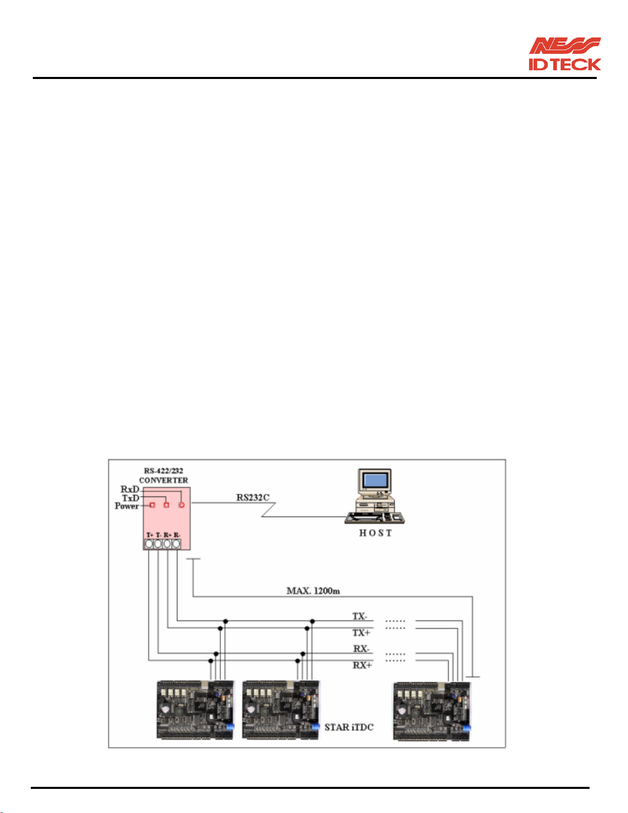
6.3.3 RS-422 CONNECTION (MULTIPLE iTDC CONNECTIONS)
RS422/RS232 converter is required to use RS422 communication between multiple iTDCs and a host
computer. Please follow the following instructions.
1 unit of iTDC can use a TCP/IP internal module for communications. And an iTDC used TCP/IP internal module
can communicate with other iTDC Controllers by RS422 method.
In this case, the communication must be connected via RS422 method.
First, you have to connect all RS422 port of all iTDCs in parallel.
- Connect RS422-TX (+) of one iTDC to RS422-TX (+) of another iTDC.
- Connect RS422-TX (-) of one iTDC to RS422-TX (-) of another iTDC.
- Connect RS422-RX (+) of one iTDC to RS422-RX (+) of another iTDC.
- Connect RS422-RX (-) of one iTDC to RS422-RX (-) of another iTDC.
Second, you have to connect one of RS422 port of iTDC to RS422/RS232 converter.
- Connect RS422-TX (+) of the one iTDC to RX (+) port of the converter.
- Connect RS422-TX (-) of the one iTDC to RX (-) port of the converter.
- Connect RS422-RX (+) of the one iTDC to TX (+) port of the converter.
- Connect RS422-RX (-) of the one iTDC to TX (-) port of the converter.
- Plug in the RS232 9-pin connector of the converter to the COM1 or COM2 Port of the PC.
- Install and run iTDC Application Software.
Figure: RS-422 Communication between iTDCs and Host Computer
101-001 (iTDC), 101-002 (EIO88), 101-145 (iTDCSR) -28- Users Manual
Page 29
IDTeck – iTDC 2~4 DOOR ACCESS CONTROLLER
6.4 DIAL UP MODEM
Please, see the Software manual.
6.5 TCP/IP MODULE (INTERNAL VERSION)
Please, see the Software manual.
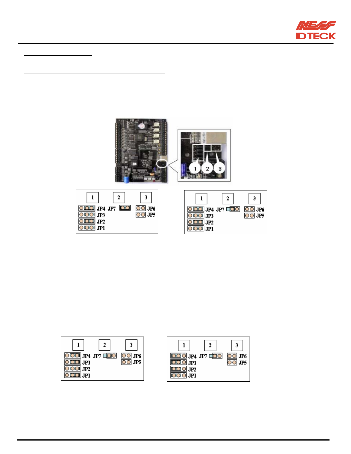
6.5.1 Jumper Switch setting (Over iTDC V3.0)
Before the LAN (TCP/IP module) Communication, the jumper switch needs to be setting with the
figure of the below.
IIM7100(IGM7100) IIM7100A
Figure: Jumper Switch location and setting for LAN (TCP/IP module) communication
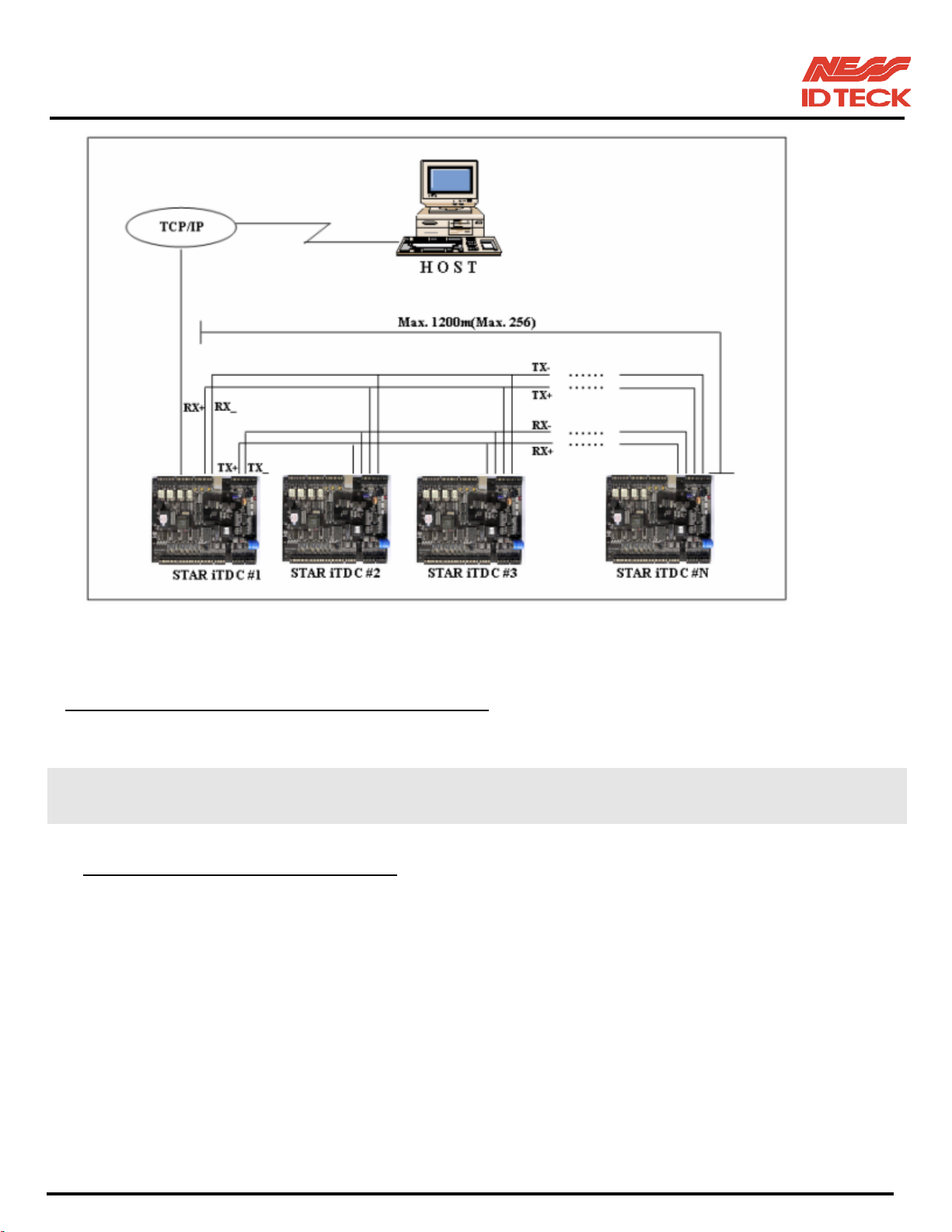
6.5.2 Multi drop Connection (by TCP/IP internal module)
This uses LAN (TCP/IP) communication between multiple iTDCs and a host computer.
Install the same as <Figure: Multi drop connection (by TCP/IP internal module)>.
Set the jumper switch the same as <Figure: Jumper switch setting for Multi drop connection (by
TCP/IP internal module)>
iTDC #1 iTDC #2 ~ #N
In this example NESS - IDTECK iTDC #1 uses IIM7100A.
Figure: Jumper switch setting for Multi drop connection (by TCP/IP internal module)
101-001 (iTDC), 101-002 (EIO88), 101-145 (iTDCSR) -29- Users Manual
Page 30
IDTeck – iTDC 2~4 DOOR ACCESS CONTROLLER
Figure: Multi drop connection (by TCP/IP internal module)
6.6 TCP/IP CONVERTER (EXTERNAL VERSION)
Please, see the Software manual.
7. OPERATION STATUS
7.1 LED INDICATORS OF THE iTDC
The LEDs for indicating the status of the iTDC are located as shown in the Figure: iTDC Layout. Each
LED will be turned on and off as the following status of the iTDC.
LED1 ~ LED2
These two LEDs indicate the communication status. LED1 blinks while the communication signal is
receiving from the PC. LED2 blinks while iTDC is sending the signals to the PC.
LED1: RxD, LED2: TxD
LED3 ~ LED6
If the TCP/IP module is installed, these LEDs indicate the status of the TCP/IP module.
LED3: Connection Status, LED4: 10M bps, LED5: 100M bps, LED6: Collision Status
101-001 (iTDC), 101-002 (EIO88), 101-145 (iTDCSR) -30- Users Manual
Page 31

IDTeck – iTDC 2~4 DOOR ACCESS CONTROLLER
LED7
This LED is always on if the iTDC is powered on.
LED8 ~ LED14
These LEDs indicate the status of the Output ports. The LED is turned on while the output is activating to
the output port.
LED8: Relay #1, LED9: Relay #2, LED10: Relay #3, LED11: Relay #4
LED12: TTL #1, LED13: TTL #2, LED14: TTL #3
LED15 ~ LED21
These LEDs indicate the status of the Input ports. The LED is turned on while the input port is activating
to low to the ground level.
LED15: Input #1, LED16: Input #2, LED17: Input #3, LED18: Input #4
LED19: Input #5, LED20: Input #6, LED21: Input #7
7.2 LED INDICATORS OF THE EIO88 EXPANSION I/O BOARD
The LEDs for indicating the status of the EIO88 Expansion I/O Board are located as shown in the Figure:
EIO88 Expansion I/O Board Layout. Each LED will be turned on and off as the following status of the
EIO88 Expansion I/O Board.
LED17
This LED is always on if the EIO88 Expansion I/O Board is powered on.
LED1 ~ LED8
These LEDs indicate the status of the Output ports of EIO88 Expansion I/O Board. The LED is turned on
while the output is activating to the output port.
LED1: Relay #1, LED2: Relay #2, LED3: Relay #3, LED4: Relay #4
LED5: Relay #5, LED6: Relay #6, LED7: Relay #7, LED8: Relay #8
LED9 ~ LED16
These LEDs indicate the status of the Input ports of EIO88 Expansion I/O Board. The LED is turned on
while the input port is activating to low to the ground level.
LED9: Input1, LED10: Input2, LED11: Input3, LED12: Input4,
LED13: Input5, LED14: Input6, LED15: Input7, LED16: Input8
101-001 (iTDC), 101-002 (EIO88), 101-145 (iTDCSR) -31- Users Manual
Page 32
IDTeck – iTDC 2~4 DOOR ACCESS CONTROLLER
8. BASIC SETTINGS
Note !!! You have to connect optional LCD display and Keypad to iTDC for the following manual settings.
8.1 INITIALIZATION OF iTDC
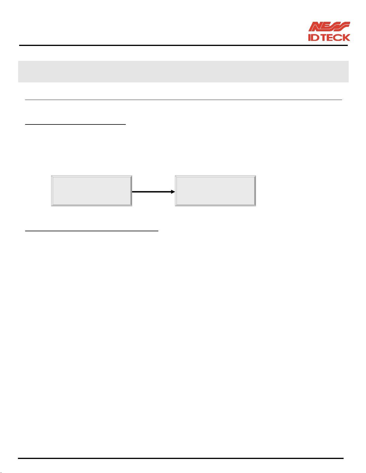
After the all installation and connections are completed, power up the iTDC then press the two
Initialisation Switches simultaneously. The LCD will first display “System Initialising…” After the all
Initialisation process is completed then the LCD will display “Initialise END Turn OFF Power.” Turn the
power off then turn on again for iTDC running.
8.2 HOW TO ENTER THE SETUP MENU
To set-up or to change the iTDC settings, you have to enter the SETUP MENU first. To do so, press the 8
Initialize END System
times <0> key for Master ID (Default setting “00000000”) and <ENT> key from the optional Keypad
then you can get into SETUP MENU. There are 4 main SETUP MENU and you first get into [SETUP
MENU F1]. You can move to other SETUP MENU by pressing <F1> key for [SETUP MENU F1],
<F2> key for [SETUP MENU F2], <F3> key for [SETUP MENU F3] and <F4> key for [SETUP
MENU F4]. There are several SUB MENU in the main SETUP MENU and you can scroll up and down
the SUB MENU by pressing <4> and <6> key in the main SETUP MENU. If you don’t press any key for
20 seconds or if you press <ESC> key then iTDC will exit the SETUP MENU then return to normal
operation. You can also change the Master ID in the [SETUP MENU F2].
The Master ID for iTDC-SR is 10 times <0> key (Default setting “0000000000”).
101-001 (iTDC), 101-002 (EIO88), 101-145 (iTDCSR) -32- Users Manual
Page 33
IDTeck – iTDC 2~4 DOOR ACCESS CONTROLLER
8.3 DOOR SETTING
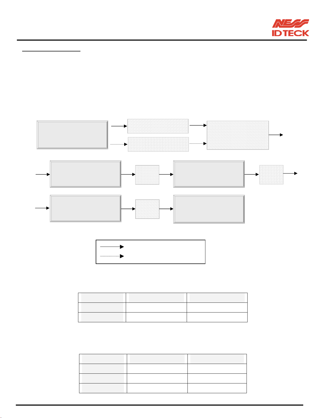
First, you have to configure “How many doors you want to control by iTDC” and this set-up is very
important, as the iTDC will automatically configure the Input sources and Output Relays upon to the
number of doors to be controlled by iTDC. Press <F2> key once then press <6> key or <4> key until the
LCD shows [DOOR SETTING] in the [SETUP MENU F2] then press <ENT> key to change the DOOR
SETTING. Please follow the steps below for DOOR SETTING and it shows the procedure for 4 DOOR
setting. The Master ID for iTDC-SR is 10 digits number (Default setting “0000000000”).
STAR iTDC [F1]
2 Door Setting
“MASTER ID” + <ENT>
8 times <0> + <ENT>
Initial LCD Display
DOOR SETTING DOOR SETTING
DOOR SETTING
<ENT>
<ENT>
DOOR
4 DOOR Setting Completed
: After Master ID change
: Initial Master ID
Press <F2> + 7times <6>
Select [
DOOR SETTING]
+ <ENT>
<4> or
<6>
Confirm the Reader locations as shown on the table below.
3 Door Setting
Entry Exit
Door1 Reader #1 Reader #2
Door2 Reader #3 Reader #4
Confirm the Reader and Exit Button locations as shown on the table below.
Entry Exit
Door1 Reader #1 Reader #2
Door2 Reader #3 EXIT Button
Door3 Reader #4 EXIT Button
101-001 (iTDC), 101-002 (EIO88), 101-145 (iTDCSR) -33- Users Manual
Page 34
IDTeck – iTDC 2~4 DOOR ACCESS CONTROLLER
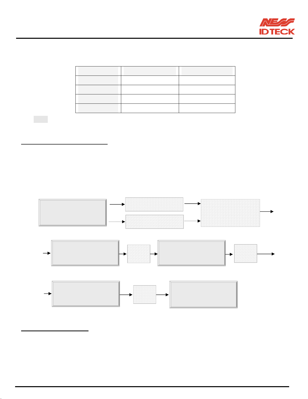
4 Door Setting
Confirm the Reader and Exit Button locations as shown on the table below.
Note! This must be set-up first before other set-up.
8.4 DATE AND TIME SETTING
Select [TIME SETTING] in the [SETUP MENU F2] and enter the Year / Month / Date / hour / minute /
second / Day (Total 15 digits) as shown below. LCD will display the new Date and Time after the time
setting completed but year and day will not be displayed. iTDC has 24 hours system and day codes are 1
for Sunday, 2 for Monday, 3 for Tuesday, 4 for Wednesday, 5 for Thursday, 6 for Friday and 7 for
Entry Exit
Door1 Reader #1 EXIT Button
Door2 Reader #2 EXIT Button
Door3 Reader #3 EXIT Button
Door4 Reader #4 EXIT Button
Saturday. The Master ID for iTDC-SR is 10 digits number (Default setting “0000000000”).
STAR iTDC [F1]
Initial Display
TIME SETTING
TIME SETTING
8.5 ID COUNT SETTING
iTDC can register maximum 20,000 User ID and you can select maximum User ID to be registered into the
“MASTER ID” + <ENT>
8 times <0> + <ENT>
<ENT>
“Year/Month/Day/Hour/Min./Sec./Day”
<ESC>
YYYYMMDDhhm
STAR iTDC
LCD displays after time setting
Select [
Press <F2>
TIME SETTING]
+ <ENT>
<ENT>
iTDC from 1,000 up to 20,000 Users in 1,000 increments. This ID COUNT setting is to configure
maximum User ID to be registered into iTDC and if you set-up less ID COUNT then iTDC will increase
the EVENT Buffer size to maximum. The default ID COUNT is 5,000 Users and the default EVENT
Buffer size is 27,500 can be stored when you operate iTDC off-line.
101-001 (iTDC), 101-002 (EIO88), 101-145 (iTDCSR) -34- Users Manual
Page 35
IDTeck – iTDC 2~4 DOOR ACCESS CONTROLLER
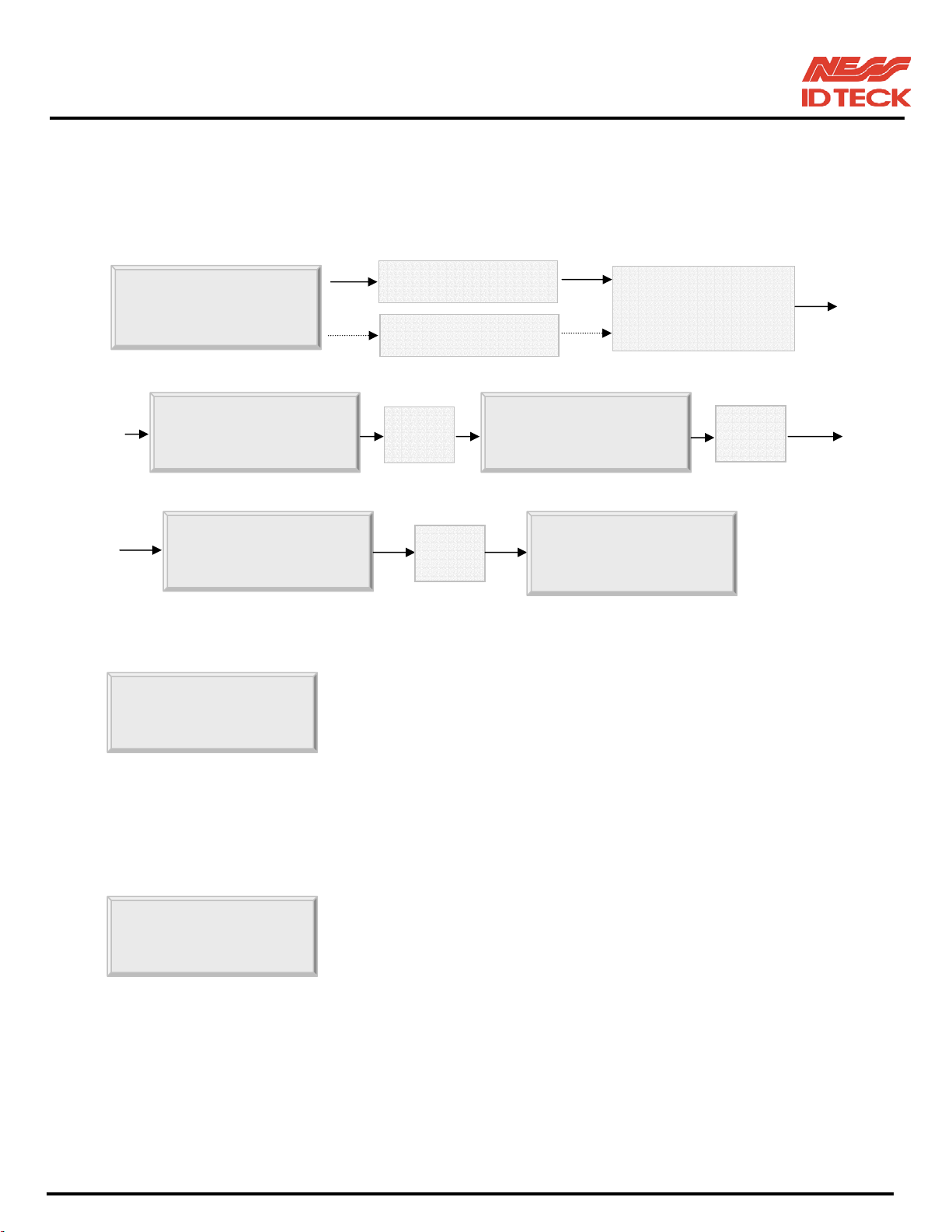
Select [ID COUNT] in the [SETUP MENU F3] then set-up the maximum User ID to be registered into
iTDC. Follow the steps to set-up ID COUNT.
The Master ID for iTDC-SR is 10 digits number (Default setting “0000000000”).
STAR iTDC [F1]
Initial Display
“MASTER ID” + <ENT>
8 times <0> + <ENT>
Press <F3> + <4> or <6>
Select [
ID COUNT]
ID COUNT ENTER ID
ID COUNT
<ENT>
Enter the number from 1000 to 20000
<ESC>
STAR iTDC [F1]
<ENT>
☞ You will see this error message when you press <ENT> key in the
EVENT MEMORY
[ID COUNT] menu and it tells you that some events are still
existing in the EVENT Buffer and you may lost the data when you
change the ID COUNT. You may try this setting again after
uploading the events to the host PC or deleting them, using the
[SETUP MENU F2] -> [EVENT CLEAR].
☞ You will see this error message when you try to change ID COUNT
ID TOTAL
less than the total registered User ID. In this case you have to delete
some User ID or clear the User ID, using the [SETUP MENU F2] -
> [ID CLEAR] first then try again from the beginning.
101-001 (iTDC), 101-002 (EIO88), 101-145 (iTDCSR) -35- Users Manual
Page 36
IDTeck – iTDC 2~4 DOOR ACCESS CONTROLLER
8.6 ID REGISTRATION
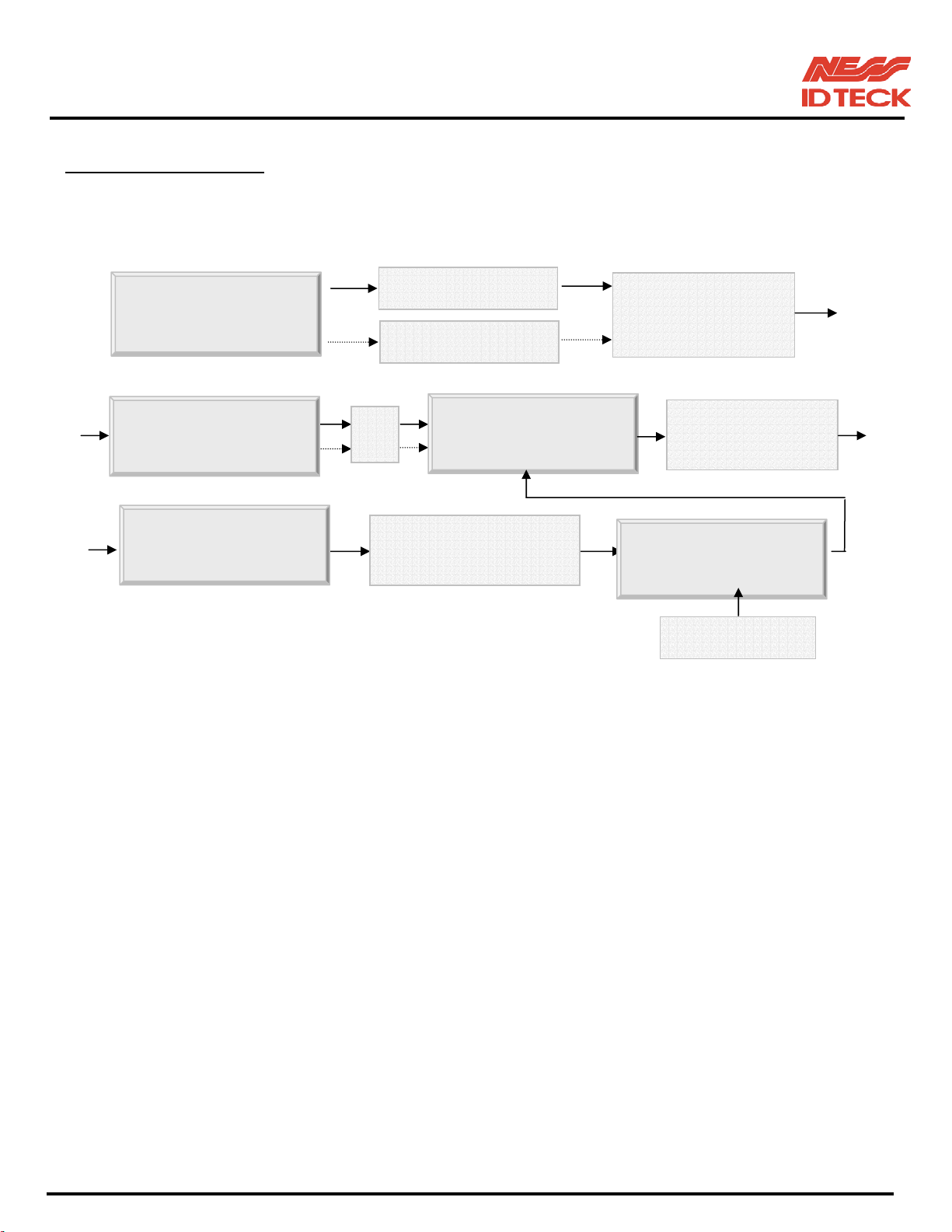
You can register the User ID into the iTDC. Select [SETUP MENU F3] -> [ID REGISTRATION] then
follow the steps below.
The Master ID for iTDC-SR is 10 digits number (Default setting “0000000000”).
STAR iTDC [F1]
Initial LCD Display
“MASTER ID” + <ENT>
8 times <0> + <ENT>
Press <F3> then
Select
[
ID REGISTRATION]
ID
<ENT>
ID [________]
ID (8digits) + <ENT>
Password (4digits) + <ENT>
TA__TB__TC__T
Time Schedule codes + <ENT>
Reader Usage codes + <ENT>
TA00TB00TC00T
1. ID [________]: ID number consists of 3-digits Facility code from 000 to 255 and 5-digits ID number
Reg. completed
from 00000 to 65535 so that the 8-digits ID number cannot exceed 25565535. If you don’t know the ID
number of the proximity cards then select [SETUP MENU F4] -> [READER TEST] then present the
card to the reader to display the ID number. Enter 8-digits ID number then press <ENT> key in the ID
[________] field. (ID number of iTDC-SR has 10-digits decimal numbers.)
2. PW [____]: PW is the password which can be used to access the doors where you install a Proximity
and Keypad Reader and set-up the RF + Password operating mode. But regardless of the operating mode,
it is necessary to enter a default password (0000) in the PW [____] field when you register ID.
3. TA__TB__TC__TD__: TA, TB, TC and TD are Time Schedule code (00-15) for the Readers, TA is the
Time Schedule for the Reader #1, TB is for Reader #2, TC is for Reader #3 and TD is for Reader #4.
When you present the card to Reader #1 then the cardholder is only allowed the access of the door during
the Time Schedule code entered to TA__ and the other Readers are the same manner. To control the
accessible Time Schedule for each cardholder, you must set-up the Time schedules first and enter the
Time Schedule code here. If you want to access the door anytime for the cardholder then enter default
Time Schedule code '00' for the value.
101-001 (iTDC), 101-002 (EIO88), 101-145 (iTDCSR) -36- Users Manual
Page 37

IDTeck – iTDC 2~4 DOOR ACCESS CONTROLLER
4. RA__RB__RC__RD__: RA, RB, RC and RD are Reader Usage codes for the cardholder. If you put ‘1’
for RA then Reader #1 is accessible and if you put ‘0’ for RA then the cardholder can not access through
the Reader #1 and iTDC generates an error message “Access Door Error” and displays on the LCD. To
get access through all 4 Readers, you have to input ‘1’ value for RA, RB, RC and RD.
8.7 OUTPUT SETTING
You can program the output behaviour by using the application software. Please refer to APPENDIX for
factory settings.
9. OPERATION
9.1 NORMAL OPERATION
Power on
When the power is applied to iTDC, the LED7 is turned on.
Registered card reading
When a registered card (or PIN) is read, the Door (Relay #1, Relay #3) will open for 3 seconds (Default)
with the LED on. (LED8, LED10)
Exit Button
To request for exit from the inside, an Exit Button (or an Exit Reader) can be used.
The Door (Relay #1, Relay #3) will open for 3 seconds with the LED on. (LED8, LED10)
Alarms
When an unregistered card is read, the access is denied and the alarm (Relay #2, Relay #4) will be
activated for 3 seconds with the LED on (LED9, LED11) along with a buzzer sound.
9.2 DEFAULT SETTING
When you operate the iTDC first time or you initialise the iTDC, the controller will set-up all values defaults
(factory settings). You can change the settings for desired application.
Please refer to the APPENDIX for the default setting values.
101-001 (iTDC), 101-002 (EIO88), 101-145 (iTDCSR) -37- Users Manual
Page 38
IDTeck – iTDC 2~4 DOOR ACCESS CONTROLLER
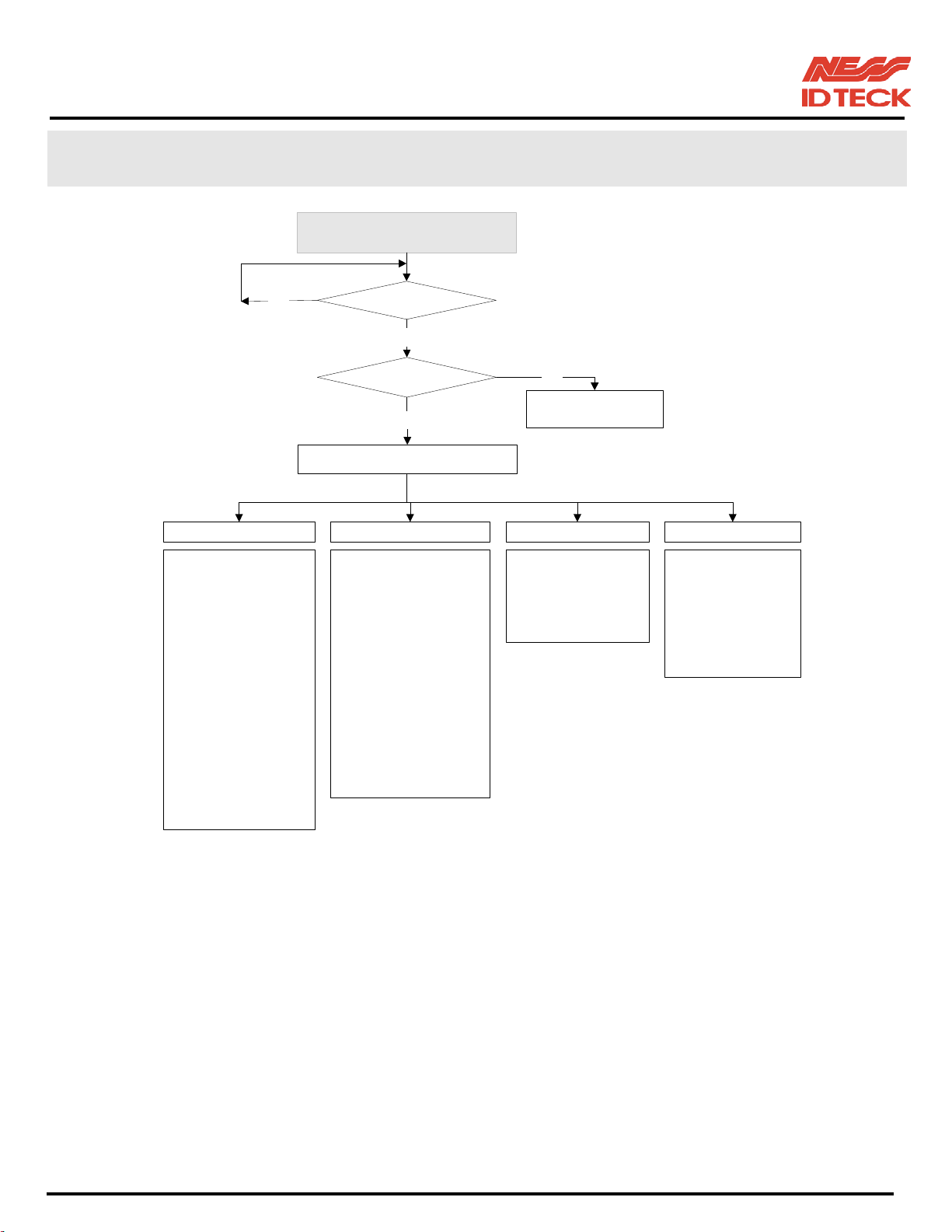
10. SETTING CHANGES
(MODEL NAME, CURRENT TIME)
INITIAL DISPLAY
NO
SETUP MENU F1 SETUP MENU F2
1. READER 1 MODE
2. READER 2 MODE
3. READER 3 MODE
4. READER 4 MODE
5. DOOR 1 APB
6. DOOR 2 APB
7. READER1 KEY IN
8. READER2 KEY IN
9. READER3 KEY IN
10. READER4 KEY IN
11. READER1 DURESS
12. READER2 DURESS
13. READER3 DURESS
14. READER4 DURESS
15. READER1 T/S
16. READER2 T.S
17. READER3 T/S
18. READER4 T/S
ID INPUT ?
YES
MASTER ID ?
YES
SETUP MENU
1. TIME SETTING
2. HOLIDAY INDEX
3. COMM ID
4. BAUD RATE
5. MASTER ID CHANGE
6. EVENT MEMORY
7. DOOR ALARM
8. DOOR SETTING
9. HOLIDAY SETTING
10. TIME SCHEDULE
11. IN/OUT DEFINE
12. READER DEFINE
13. SYSTEM INITIALIZE
14. EVENT CLEAR
15. CARD ID CLEAR
16. TIME SCHE CLEAR
NORMAL OPERATION
SETUP MENU F3
1. ID REGISTRATION
2. ID DELETE
3. ID LIST
4. REG. ID COUNT
5. ID COUNT
6. EVENT COUNT
NO
MODE
SETUP MENU F4
1. VERSION
2. SRAM TEST
3. OUTPUT TEST
4. LCD TEST
5. KEYPAD TEST
6. READER TEST
7. INPUT TEST
8. COMM TEST
☞. To set-up or to change the iTDC settings, you have to enter the SETUP MENU first. To do so,
press 8 times <0> key for Master ID (Default setting “00000000”) and <ENT> key from the
optional Keypad then you can get into SETUP MENU. There are 4 main SETUP MENU and
you first get into [SETUP MENU F1]. You can move to other SETUP MENU by pressing
<F1> key for [SETUP MENU F1], <F2> key for [SETUP MENU F2], <F3> key for [SETUP
MENU F3] and <F4> key for [SETUP MENU F4]. There are several SUB MENU in the main
SETUP MENU and you can scroll up and down the SUB MENU by pressing <4> and <6> key
in the main SETUP MENU. If you don’t press any key for 20 seconds or if you press <ESC>
key then iTDC will exit the SETUP MENU then return to normal operation.
The Master ID for iTDC-SR is 10 times <0> key (Default setting “0000000000”).
101-001 (iTDC), 101-002 (EIO88), 101-145 (iTDCSR) -38- Users Manual
Page 39
IDTeck – iTDC 2~4 DOOR ACCESS CONTROLLER
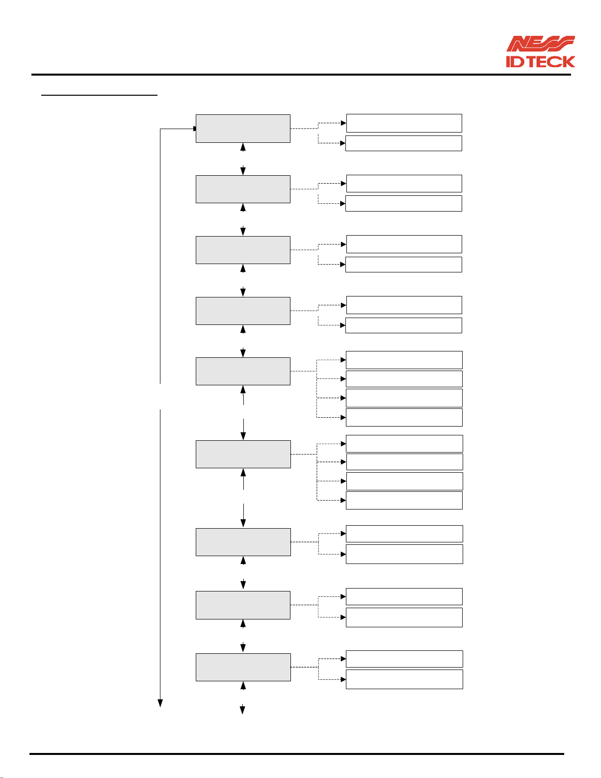
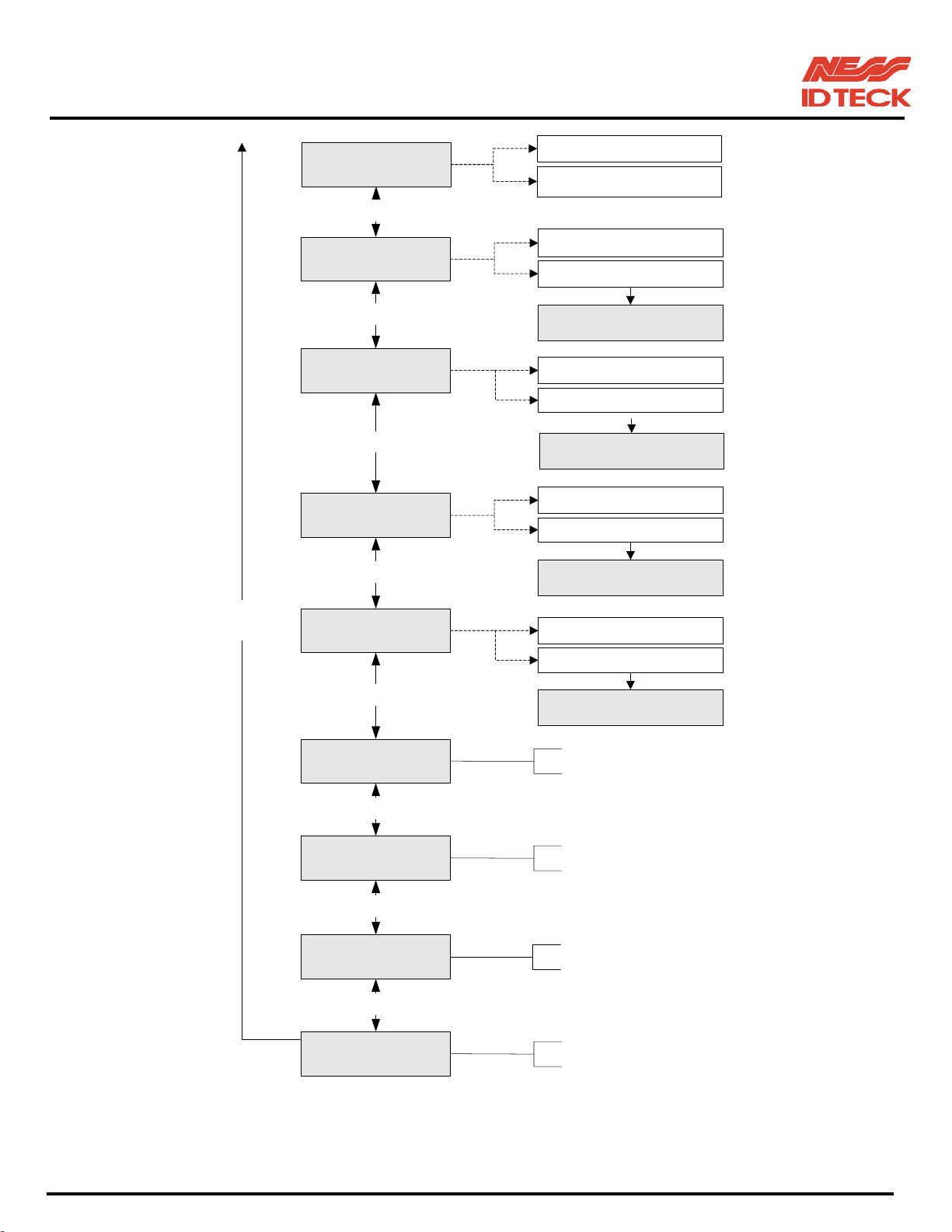
10.1 SETUP MENU F1
Searching key
<4> or <6>
READER 1 MODE
key<4> or <6>
READER 2 MODE
key<4> or <6>
READER 3 MODE
key<4> or <6>
READER 4 MODE
key<4> or <6>
DOOR 1 APB
key<4> or <6>
RF Only (default)
RF+PASSWORD
RF Only (default)
RF+PASSWORD
RF Only (default)
RF+PASSWORD
RF Only (default)
RF+PASSWORD
NOT USE (default)
USE(ALONE)
USE(ZONE)
ALL CLEAR
DOOR 2 APB
key<4> or <6>
READER1 KEY IN
key<4> or <6>
READER2 KEY IN
key<4> or <6>
READER3 KEY IN
key<4> or <6>
NOT USE (default)
USE(ALONE)
USE(ZONE)
ALL CLEAR
DISABLE (default)
ENABLE
DISABLE (default)
ENABLE
DISABLE (default)
ENABLE
101-001 (iTDC), 101-002 (EIO88), 101-145 (iTDCSR) -39- Users Manual
Page 40
IDTeck – iTDC 2~4 DOOR ACCESS CONTROLLER
DISABLE (default)
READER4 KEY IN
ENABLE
key<4> or <6>
NOT USE (default)
READER 1 DURESS
USE
Searching key
<4> or <6>
key<4> or <6>
READER 2 DURESS NOT USE (default)
key<4> or <6>
READER 3 DURESS
key<4> or <6>
READER 4 DURESS NOT USE (default)
key<4> or <6>
READER 1 T/S
DURESS 1 P/W
USE
DURESS 2 P/W
NOT USE (default)
USE
DURESS 3 P/W
USE
DURESS 4 P/W
2 Digit number
key<4> or <6>
READER 2 T/S
key<4> or <6>
READER 3 T/S
key<4> or <6>
READER 4 T/S
2 Digit number
2 Digit number
2 Digit number
101-001 (iTDC), 101-002 (EIO88), 101-145 (iTDCSR) -40- Users Manual
Page 41
IDTeck – iTDC 2~4 DOOR ACCESS CONTROLLER
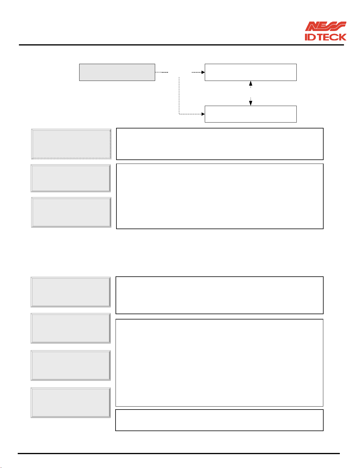
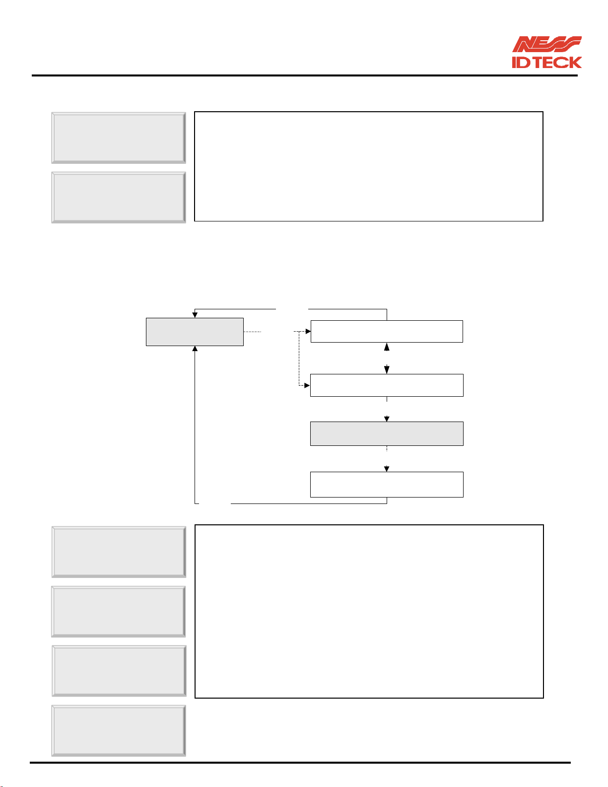
10.1.1 READER MODE SETTING
READER1
READER1
READER1
* READER2, READER3 and READER4 MODE set-up is the same as above.
10.1.2 ANTI-PASS-BACK MODE SETTING
DOOR 1 APB
DOOR 1 APB
DOOR 1 APB
DOOR 1 APB
* DOOR2 APB mode set-up is the same as above.
READER 1 MODE
☞. It shows READER1 MODE is set to RF ONLY operating mode.
If you want to change the mode to RF+PASSWORD operating
☞. Now you can change the mode by pressing <4> or <6> key to
toggle the mode. If you want to set-up the mode displayed then
press <ENT> key to accept this mode.
Note:
RF ONLY: The door is accessible with the proximity card alone.
RF+PASSWORD: The door is accessible with the proximity card
☞. It shows Door1 anti-pass-back operation is not used. Press
<ENT> key. (It only applies when the Door has Exit Reader)
z For Door1 (2), you must have Reader #1(#2) for entry and
☞. Press <4> or <6> key for searching the APB mode.
Press <ENT> key to select the mode.
NOT USE: Anti-pass-back mode is not applied.
USE (ALONE): Door1 (2) Anti-pass-back mode is separately applied.
USE (ZONE): Door1 (2) Anti-pass-back mode is applied together.
Note: If you select USE (ZONE) then the APB flag will be affected
Example: When you select USE (ALONE) then Door2 entry is possible
☞. If you select All Clear then iTDC will clear all APB flags and all
RF Only (default)<ENT>
Seaching key<4> or <6>
RF+PASSWORD
<
>
and Password.
to Door1 and Door2. DOOR2 APB mode is set automatically.
after you got in through Door1.
When you select USE (ZONE) then Door2 entry is not
101-001 (iTDC), 101-002 (EIO88), 101-145 (iTDCSR) -41- Users Manual
Page 42
IDTeck – iTDC 2~4 DOOR ACCESS CONTROLLER
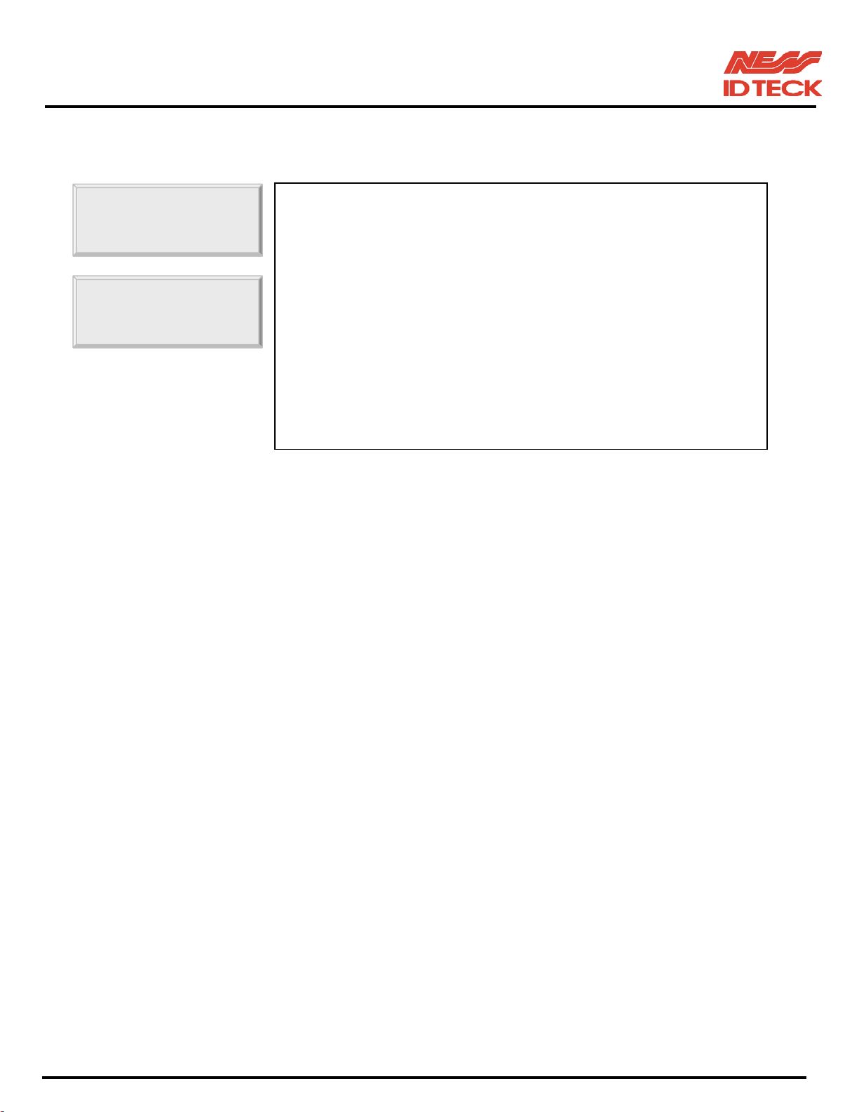
10.1.3 KEYPAD INPUT SETTING
READER1 KEY
READER1 KEY
☞. This function is to set DISABLE/ENABLE the keypad inputs
from the Proximity and Keypad Readers. The default setting is
DISABLE the keypad inputs. If you install Keypad Reader (8bit
burst format) and set this mode ENABLE, you can access the
Door by pressing 8digit User ID from the keypads.
Press <ENT> key and press <4> or <6> key to select ->ENABLE
then press <ENT> key to set-upthis function.
* READER2, READER3 and READER4 KEY IN set-up is the same as above.
10.1.4 DURESS MODE SETTING
<ENT>
READER 1 DURESS
<ENT>
NOT USE(default)
Searching key<4> or <6>
USE
<ENT>
DURESS 1 P/W
<ENT>
ENTER NEW P/W
(2digit + <ENT>)
<ENT>
READER1
☞. You can select whether the DURESS mode is used or not used for
READER1. To use this function, you need Keypad Reader.
Default setting is NOT USE. If you want to set-up Duress mode
then press <ENT> key and select ->USE by pressing <4> or <6>
READER1
key then press <ENT> key. LCD will display default Duress
Password ‘00’. Press <ENT> key again to enter 2 digit Duress
Password then press <ENT> key to finish setting.
DURESS 1 P/W
Note!!
In case of Duress, enter the 2 digit Duress Password and <ENT>
key then present the card. Door will be opened as normal but the
DURESS 1 P/W
101-001 (iTDC), 101-002 (EIO88), 101-145 (iTDCSR) -42- Users Manual
Page 43
IDTeck – iTDC 2~4 DOOR ACCESS CONTROLLER
* READER2, READER3 and READER4 DURESS set-up is the same.
10.1.5 READER TIME SCHEDULE SETTING
READER1 T/S
READER1 T/S
☞. If you set-up RF+PASSWORD operating mode for Reader #1
(Refer to READER1 MODE SETTING), you can apply Time
Schedule for Reader #1. During the time period of Time Code in
the T/S, Reader #1 will operate RF ONLY mode. And the rest of
time period, Reader #1 will operate RF+PASSWORD mode.
To apply this function, you have to set-up Time Schedules (T/S)
and Holiday Schedules (H/S) from the iTDC Application Software
and download T/S with H/S index to the iTDC. Please read iTDC
Software Manual for detail.
Select READER1 T/S then press <ENT> key. Enter 2 digit T/S
‘
’~‘
’
* READER2, READER3 and READER4 T/S set-up is the same as above.
101-001 (iTDC), 101-002 (EIO88), 101-145 (iTDCSR) -43- Users Manual
Page 44
IDTeck – iTDC 2~4 DOOR ACCESS CONTROLLER
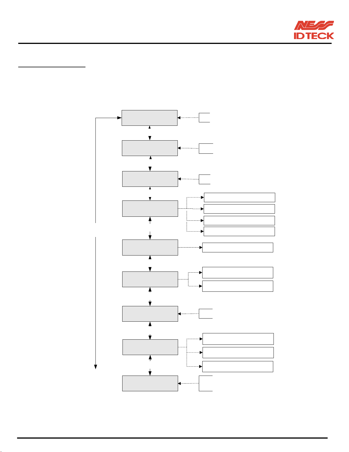
10.2 SETUP MENU F2
Searching key
<4> or <6>
TIME SETTING
key<4> or <6>
HOLIDAY INDEX
key<4> or <6>
COMM ID
key<4> or <6>
BAUD RATE
key<4> or <6>
MASTER ID CHANGE
key<4> or <6>
EVENT MEMORY
15 Digit key in
Setup each T/S index(2 Digit)
Display Communication ID
4800
9600(default)
19200
38400
KEY ( 8 Digit )
USE (default)
NOT USE
key<4> or <6>
DOOR ALARM
key<4> or <6>
DOOR SETTING
key<4> or <6>
HOLIDAY SETTING
2 Digit ( default 3 second )
2 DOOR(default)
3 DOOR
4 DOOR
INDEX : 01 ~ 10
No.: 01 ~ 100
101-001 (iTDC), 101-002 (EIO88), 101-145 (iTDCSR) -44- Users Manual
Page 45
IDTeck – iTDC 2~4 DOOR ACCESS CONTROLLER
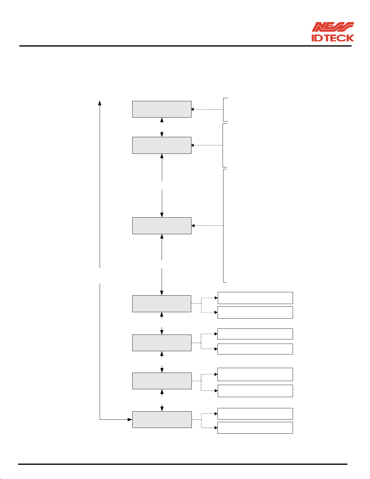
INDEX : 01 ~ 15
TIME SCHEDULE
WEEKLY: HOL, SUN, MON, …. SAT
No.: 01 ~ 05
Searching key
<4> or <6>
key<4> or <6>
IN/OUT DEFINE
key<4> or <6>
READER DEFINE
key<4> or <6>
SYS INITIALIZE
01 ~ 07: INPUT #1 ~ #7
08 ~ 15: EIO INPUT #1 ~ #8
16 ~ 19: DURESS MODE #1 ~ #4
20: OUTPUT T/S
21: INPUT T/S
22: INPUT TYPE
01: R1 ID OK
02: R1 ID ERROR
03: R1 ID T/S ERROR
04: R1 APB ERROR
05: R2 ID OK
06: R2 ID ERROR
07: R2 ID T/S ERROR
08: R2 APB ERROR
09: R3 ID OK
10: R3 ID ERROR
11: R3 ID T/S ERROR
12: R3 APB ERROR
13: R4 ID OK
14: R4 ID ERROR
15: R4 ID T/S ERROR
16: R4 APB ERROR
YES
NO
key<4> or <6>
YES
EVENT CLEAR
NO
key<4> or <6>
YES
CARD ID CLEAR
NO
key<4> or <6>
TIME SCHE CLEAR
YES
NO
101-001 (iTDC), 101-002 (EIO88), 101-145 (iTDCSR) -45- Users Manual
Page 46
IDTeck – iTDC 2~4 DOOR ACCESS CONTROLLER
b
p
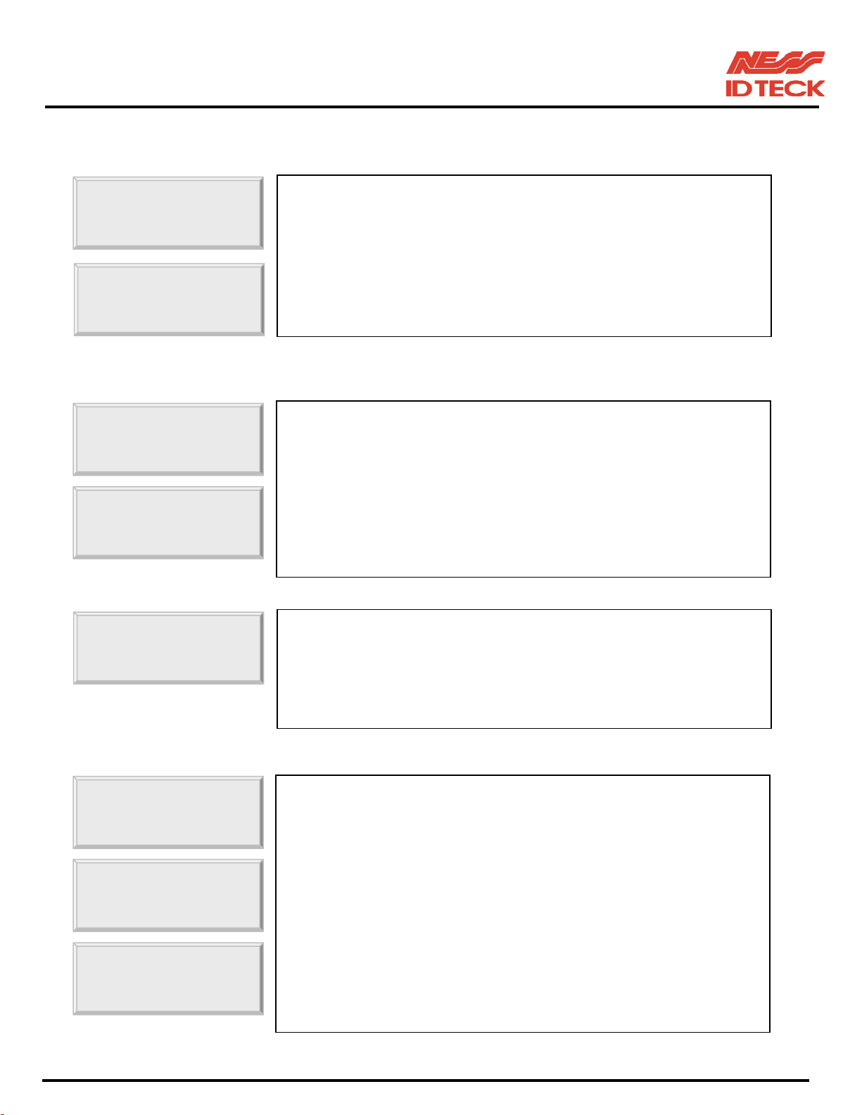
10.2.1 TIME SETTING
TIME SETTING
YYYYMMDDhhmmssW
_ _ _ _ _ _ _ _ _ _
10.2.2 HOLIDAY INDEX SETTING
HOLIDAY
T/S_INDEX 01
10.2.3 COMMUNICATION ID (ADDRESS) DISPLAY
COMM ID
☞. Press <ENT> key and enter 15 digit Date/Time codes then
<ENT> key to finish setting.
YYYY: Year, MM: Month, DD: Date
hh: Hours (24 hours system), mm: Minutes, ss: Seconds
W: Sun=1, Mon=2, Tue=3, Wed=4, Thu=5, Fri=6, Sat=7
Example: 200302101330152 => Feb.10,2003 13:30:15 Mon
☞. Holiday Index is to link the Holiday Schedule (H/S) to Time
Schedule. You can set-up one of holiday index (01~10) to one of
T/S index (01~15) so that the Holiday Time Code in the T/S can
e applied for the Holidays in the H/S. Default HOLIDAY
CODE is ‘00’ which means no holidays are applied to T/S.
Select HOLIDAY INDEX menu and press <ENT> then select
desired T/S_INDEX (01~15) by pressing <4> or <6> key then
ress <ENT> key to input 2 digit HOLIDAY CODE and <ENT>.
☞. This menu shows the current communication ID of the iTDC. If
multiple iTDC units are connected to one host PC, each unit
must be configured to different communication ID.
Note:
You can change COMM ID by DIPswitch setting of the iTDC.
10.2.4 BAUD RATE SETTING
BAUD RATE
BAUD RATE
BAUD RATE
☞. iTDC supports 4800, 9600, 19200 and 38400bps of baud rate and
default setting are 9600bps. Wrong baud rate setting will cause
communication errors and you have to set same baud rate to
iTDC and host PC. If you have communication problem,
please check followings;
- Check COMM ID of iTDC and host PC
- Check BAUD RATE of iTDC and host PC
- Check communication port and cable
- Check COM port set-up of host PC
Parity: None, Data Bit: 8 bit, Stop Bit: 1 bit
To change the baud rate, press <ENT> key and select desired
baud rate by pressing <4> or <6> key then press <ENT> key.
101-001 (iTDC), 101-002 (EIO88), 101-145 (iTDCSR) -46- Users Manual
Page 47
IDTeck – iTDC 2~4 DOOR ACCESS CONTROLLER
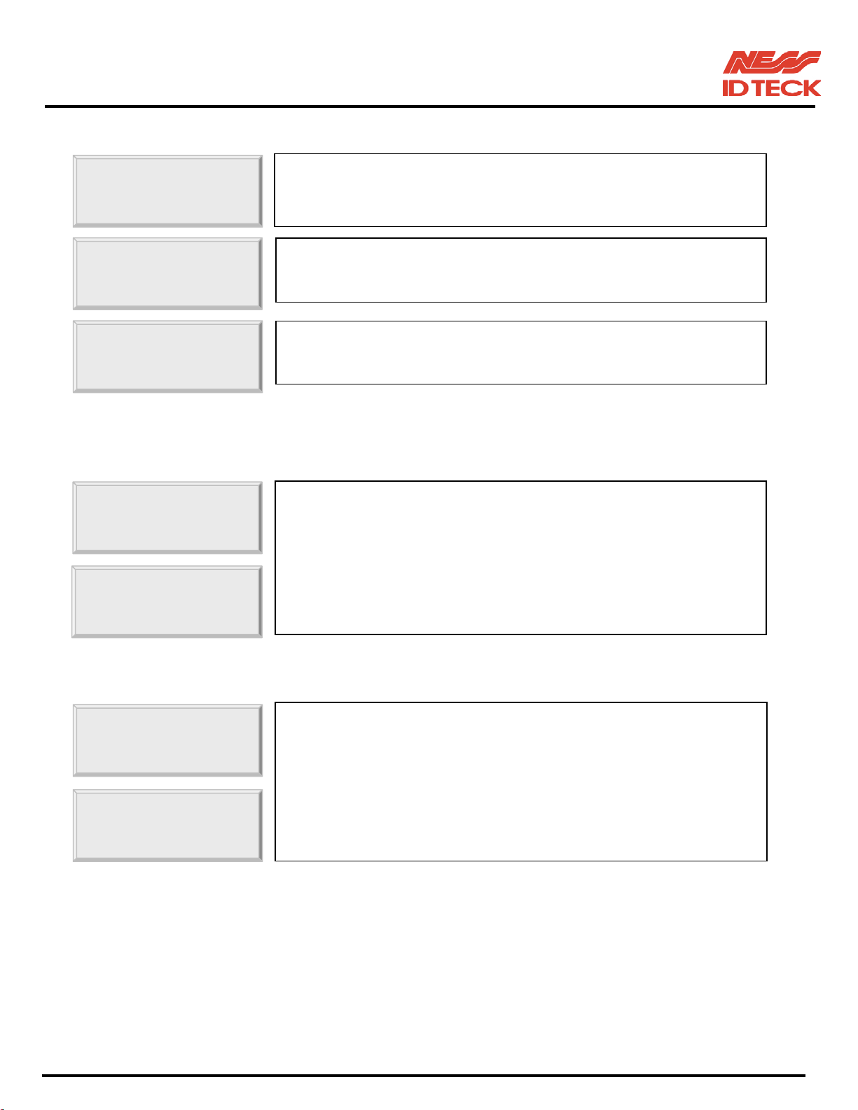
10.2.5 MASTER ID CHANGE
MASTER ID CHANGE
MASTER ID CHANGE
Master Card
The Master ID for iTDC-SR is 10 digits number (Default setting “0000000000”).
10.2.6 EVENT MEMORY SETTING
EVENT
EVENT
☞. Press <ENT> key to change the current Master ID (“00000000”).
You should use the new Master ID to access the SETUP MENU
☞. You should use 8 digits number for Master ID. Press <ENT> key
and enter the new 8 digits Master ID and <ENT> key.
☞. Master ID is now changed and stored in the memory. LCD shows
new Master ID is registered successfully.
☞. You can select whether you use event memory or not. When you
select USE and in case of event memory full then iTDC generates
an error message and keeps all events stored in the memory.
When you select NOT USE then iTDC will not generate an error
and new event overwrite into the event buffers. If you use iTDC
for standalone (just for door access) then select NOT USE.
10.2.7 DOOR OPEN ALARM SETTING
DOOR ALARM
☞. When the door is still opened after the door unlock time, you may
set this alarm function. To use this function, you have to install
Door Contact Sensor on the door and set-up the output of Door
Contact Sensor from the iTDC Application Software. ‘03’ default
DOOR ALARM
00: Alarm if the door is opened after the door unlock time
01~98: Alarm if the door is opened after the set time (01~98s)
99: No alarm
101-001 (iTDC), 101-002 (EIO88), 101-145 (iTDCSR) -47- Users Manual
Page 48
IDTeck – iTDC 2~4 DOOR ACCESS CONTROLLER
10.2.8 DOOR SETTING
DOOR
☞. Set-up how many doors to be controlled by the iTDC.
2 DOOR: Reader#1-Door1 Entry, Reader#2-Door1 Exit
Reader#3-Door2 Entry, Reader#4-Door2 Exit
3 DOOR: Reader #1-Door1 Entry, Reader #2-Door1 Exit
Reader#3-Door2 Entry, Reader#4-Door3 Entry
DOOR
4 DOOR: Reader#1, #2, #3, #4-Door1, 2,3,4 Entry
Note! This must be set-up first before other set-up.
Please refer to section 8.3 DOOR SETTING.
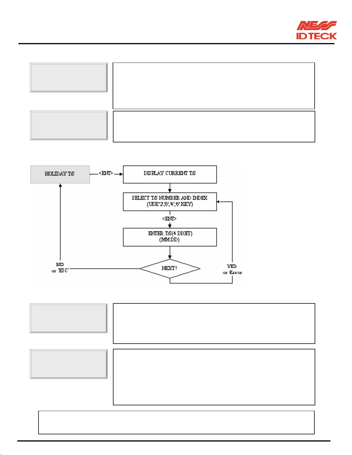
10.2.9 REGISTERING AND CHANGING HOLIDAY TIME
SCHEDULE
HOLIDAY
. You can register up to 100 specified “holidays,” per year for each
schedule setting. There can be 10 other registration sets created,
meaning holidays can be set for up to 10 years. Press <ENT> to
HOL T/S: 01 #001
. 1) Holiday Time schedule (Date registration set) number: 01 ~ 10(10 years)
2) Index for the days: 01 ~ 100(100 days)
register the days.
. With the <2> key and <8> key, select the Date Registration Set
Number (1~10), and with the <4> key and <6> key, select the
index for the days (1~100). Press <ENT> key and the cursor will
blink. Enter the date, in form of the Month (1~12). The LCD will
indicate the defined date. Now a day has been registered. For
further registration, repeat the process.
101-001 (iTDC), 101-002 (EIO88), 101-145 (iTDCSR) -48- Users Manual
Page 49
IDTeck – iTDC 2~4 DOOR ACCESS CONTROLLER
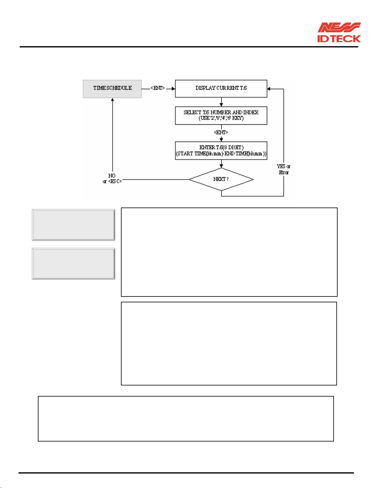
10.2.10 REGISTERING AND CHANGING TIME SCHEDULE
TIME
T/S: 01 HOL #1
. You may program time schedules to grant and restrict access for
each user. There can be up to 15 different schedules. A minimum
of one schedule must be defined.
If only one schedule is programmed the most common setting
allows access for all users 24 hours / day. A time schedule can be
programmed for each day of the week and holidays, and five
shifts can be defined for each day. To set time schedules, press
<ENT> key from this menu.
If you want to set time schedules, press <ENT> key when this
figure is displayed.
. Press <2> key or <8> key to adjust the Time Schedule (T/S)
number (1-15) and the day of the week (Mon-Sun and ‘HOL’).
Define which shift of the day (1-5), using the <4> key and <6>
key. ‘HOL’ refers to specific holidays you will register. Press
<ENT> key, and the cursor will blink, then enter the beginning
time of the period, in the form of hour (2-digit): minute (2-digit)
and the ending time in the same form. Then the lower line will
indicate the defined period. For more schedules, repeat the
process. To end time scheduling, press <ESC> key.
. Possible values for time scheduling
1) Time schedule number: 01 ~ 15 (Needed when IDs are registered)
2) A day of the week: MON, TUE, WED, THU, FRI, SAT, SUN, HOL
3) Index: 1 ~ 5(referred to the five periods of time of a day)
101-001 (iTDC), 101-002 (EIO88), 101-145 (iTDCSR) -49- Users Manual
Page 50
IDTeck – iTDC 2~4 DOOR ACCESS CONTROLLER
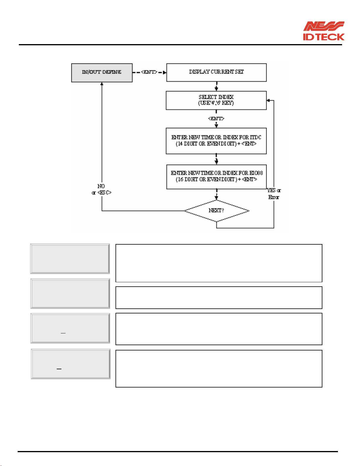
10.2.11 DEFINING OUTPUTS IN COMPLIANCE WITH INPUTS
IN/OUT DEFINE
1.INPUT #1
iTDC: 03 00 00
EIO: 00 00 00
. You can program or deactivate each output to be generated and
choose how long (in seconds) they will last. There are default
values as seen in the APENDIX (A. THE RELATION
BETWEEN INPUT AND OUTPUT (DEFAULT)
☞. Select input sources by changing Index numbers with the keys
<4> or <6>.
☞. Press <ENT> key and you will see a cursor blinking at the first
digit from the left of the seven couples of digits (Output of iTDC).
Enter the 14 digit (seven couples) key.
☞. Press <ENT> key and you will see a cursor blinking at the first
digit from the left of the eight couples of digits (Output of EIO88).
To set time for eight couples, press <ENT> key.
For more inputs,
<
>
101-001 (iTDC), 101-002 (EIO88), 101-145 (iTDCSR) -50- Users Manual
Page 51
IDTeck – iTDC 2~4 DOOR ACCESS CONTROLLER
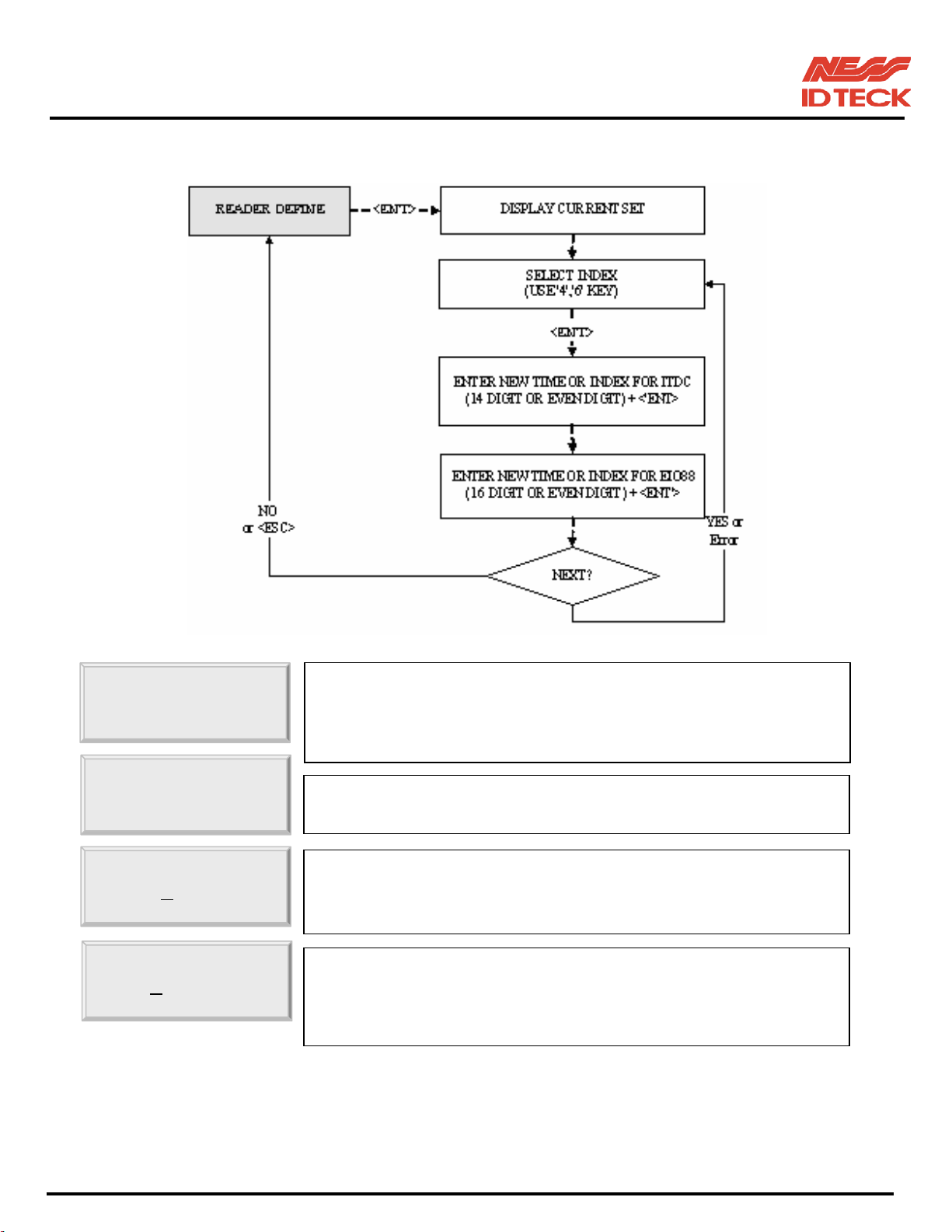
10.2.12 DEFINING OUTPUTS IN COMPLIANCE WITH READER
READER/OUT
1.R1 ID OK
iTDC: 03 00 00
EIO: 00 00 00
. You can program or deactivate each output to be generated and
choose how long (in seconds) they will last. There are default
values as seen in the APENDIX (A. THE RELATION
BETWEEN INPUT AND OUTPUT (DEFAULT)
☞. Select input sources by changing Index numbers with the keys
<4> or <6>.
☞. Press <ENT> key and you will see a cursor blinking at the first
digit from the left of the seven couples of digits(Output of iTDC).
Enter the 14 digit (seven couples) key.
☞. Press <ENT> key and you will see a cursor blinking at the first
digit from the left of the eight couples of digits(Output of EIO88).
To set time for eight couples, press <ENT> key. For more inputs,
<
>
101-001 (iTDC), 101-002 (EIO88), 101-145 (iTDCSR) -51- Users Manual
Page 52
IDTeck – iTDC 2~4 DOOR ACCESS CONTROLLER
y
y
y
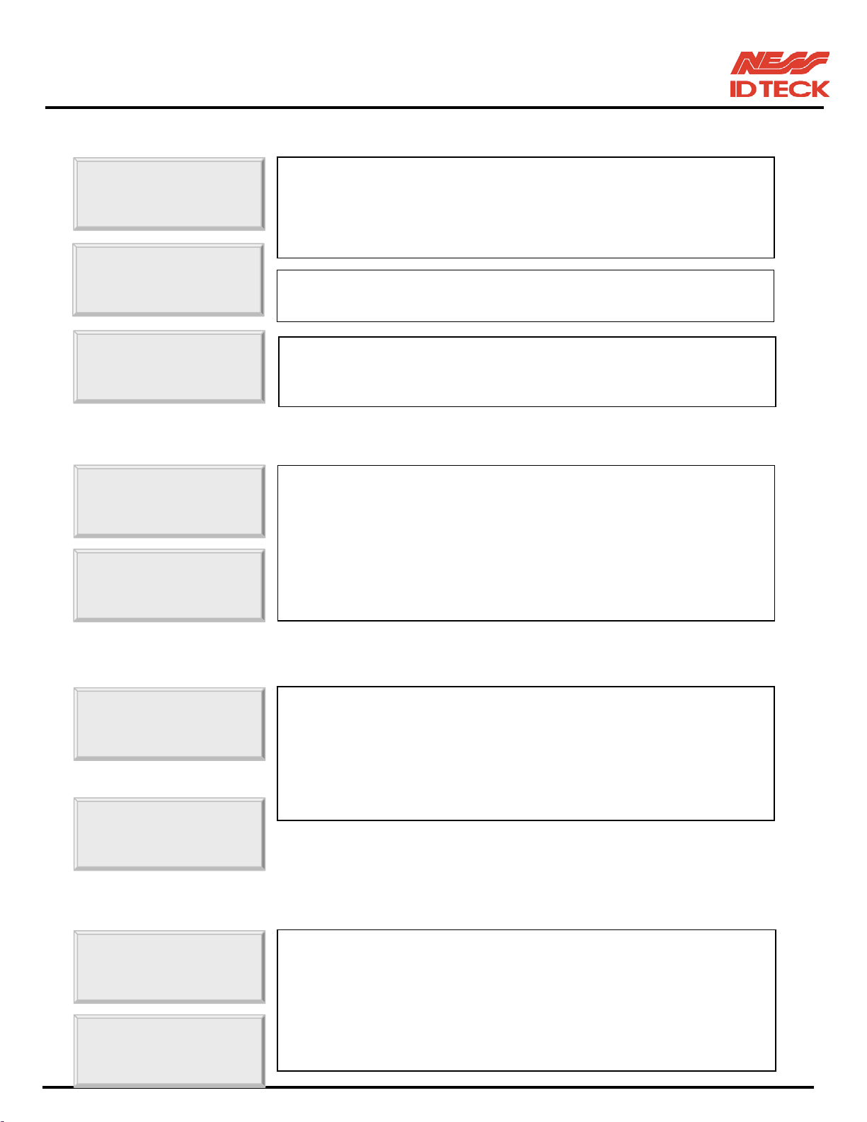
10.2.13 SYSTEM INITIALIZE
SYS INITIALIZE
SYS INITIALIZE
System
10.2.14 EVENT CLEAR
EVENT
EVENT
10.2.15 CARD ID CLEAR
☞. This operation will initialise the iTDC. Press <ENT> key, if an
initialisation is needed. (First time installation or resetting in the
event of a malfunction).
CAUTION: Initialising will erase all stored data in the memory.
☞. Press <1> key to initialise or <0> key to cancel the operation.
☞. This message appears while the system is being initialised.
After the initialisation, iTDC will return to the set-up menu.
☞. When the event memory is full or when you want to change ID
COUNT, you can clear the event memory in this menu. Press
<ENT> key then press <1> key to clear event memory or <0>
key to cancel the operation.
CAUTION: Before you clear the events, make sure that the
stored events is not necessary to upload to the host
PC otherwise you may lose important data.
☞. When you want to delete all User ID (Card ID), you can clear all
CARD ID CLEAR
CARD ID CLEAR
User ID from the memory. Press <ENT> key then press <1> key
to clear all User ID or <0> key to cancel the operation.
CAUTION: Before
ou clear all User ID, make sure that the
registered User ID is no longer used otherwise
ou
10.2.12 TIME SCHEDULE CLEAR
TIME SCHE
TIME SCHE
☞. When you want to delete all Time Schedule (01~15), you can
clear all T/S from the memory. Press <ENT> key then press <1>
key to clear all T/S or <0> key to cancel the operation.
CAUTION: Before you clear all T/S, make sure that the stored
T/S is no longer used otherwise
stored T/S in the memory.
ou may lose all
101-001 (iTDC), 101-002 (EIO88), 101-145 (iTDCSR) -52- Users Manual
Page 53
IDTeck – iTDC 2~4 DOOR ACCESS CONTROLLER
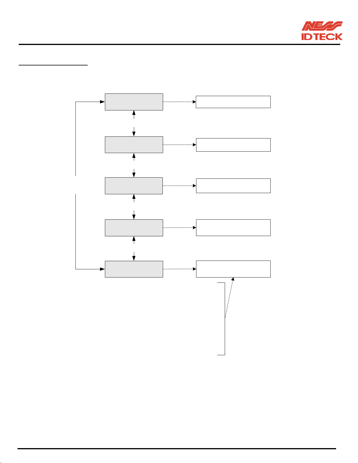
10.3 SETUP MENU F3
ID REGISTRATION
key<4> or <6>
ID DELETE
key<4> or <6>
KEY
KEY
Searching key
<4> or <6>
ID LIST
key<4> or <6>
REG. ID COUNT
key<4> or <6>
ID COUNT
DISPLAY REGISTERED
ID DATA
DISPLAY REGISTRATION
ID COUNT
ENTER POSSIBLE
REGISTRATION ID COUNT
ID / EVENT
1,000 / 29,500
2,000 / 29,000
3,000 / 28,500
4,000 / 28,000
5,000 / 27,500
: / :
: / :
10,000 / 25,000
20,000 / 20,000
101-001 (iTDC), 101-002 (EIO88), 101-145 (iTDCSR) -53- Users Manual
Page 54
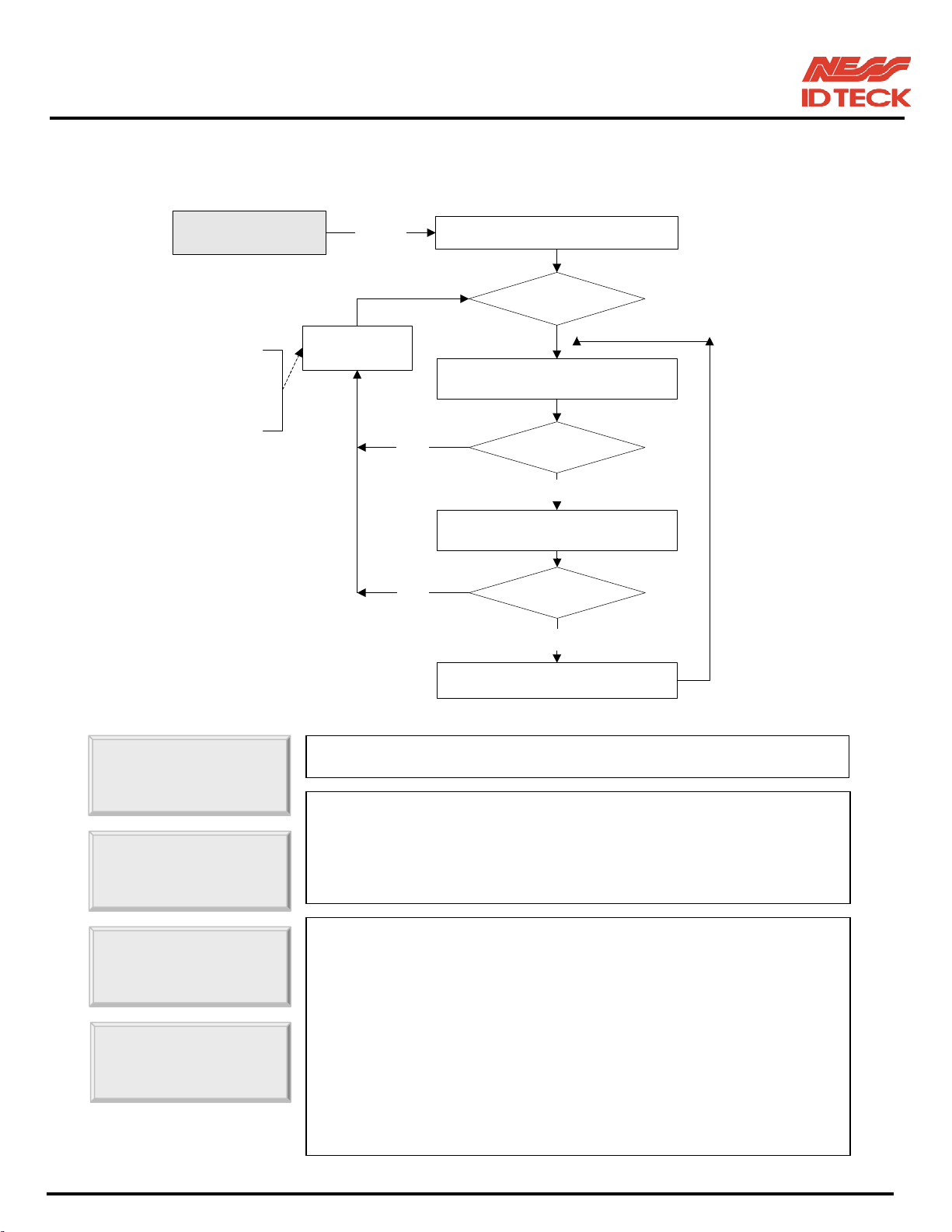
IDTeck – iTDC 2~4 DOOR ACCESS CONTROLLER
10.3.1 CARD REGISTRATION
ID REGISTRATION <ENT> REGISTRATION SELECT
KEY ?
ERROR
Invalid Card ID
Invalid T/S 1
Invalid T/S 2
Invalid RD
DISPLAY
YES
ENTER NEW ID
(8 digit - Card data)
Card ID Error ?YES
NO
INPUT
PW, TS, RD
PW, TS, RD Error ?
NO
ID REGISTRATION END
☞. Press <ENT> key to register new User ID.
ID
ID [________]
☞. Enter 8 digit Card ID in the ID [________] field and press
<ENT> key. Enter 4 digit Password in the PW [____] field and
press <ENT> key. Even you don’t use Password, it is necessary
to enter 4 digit Password as default. (Example: ‘0000’)
☞. Enter 2 digit T/S index to TA, TB, TC and TD and <ENT> key.
TA__TB__TC__T
This T/S will be applied to each Reader.
Enter <1> key to use the Reader or <0> key for no use and
<ENT> key to finish the setting.
Example: When you want to apply T/S 01 for Reader#1(TA),
T/S 02 for Reader#2(TB), T/S 02 for Reader#3(TC) and T/S 00
for Reader#4(TD) and you want to use Reader#1, #2, #3 only.
Press <0><1><0><2><0><2><0><0><ENT> key for T/S
Press <1><1><1><0><ENT> key for Reader use/not use
101-001 (iTDC), 101-002 (EIO88), 101-145 (iTDCSR) -54- Users Manual
Page 55
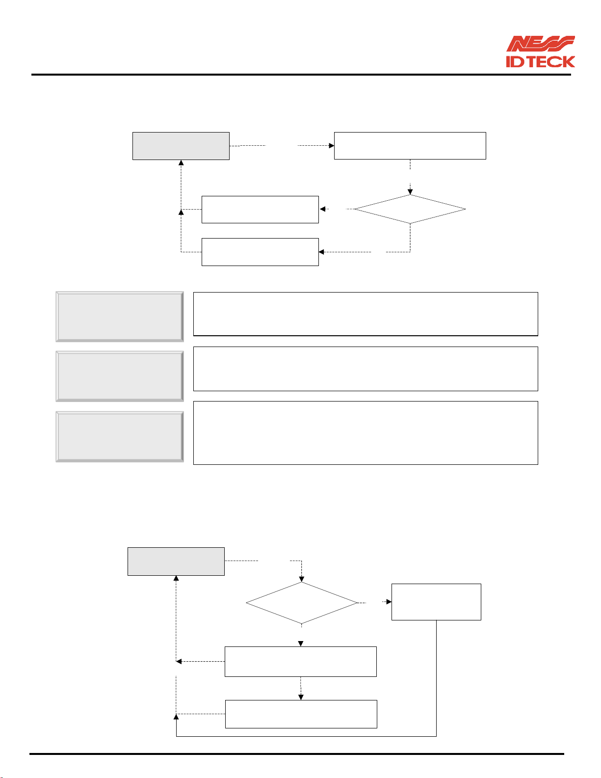
IDTeck – iTDC 2~4 DOOR ACCESS CONTROLLER
ID number of iTDC-SR is 10 digits decimal number.
10.3.2 ID DELETE
ID DELETE
<ENT>
ENTER CARD NUMBER
(8 Digit)
<ENT>
ID DELETE
Enter Card No.
☞. Press <ENT> key to delete registered User ID
☞. Enter 8 digit User ID that you want to delete and <ENT>.
☞. If the User ID you entered is found, the User ID will be deleted
LCD Display
"ID DELETED"
LCD Display
"UNREGISTERED ID"
and display “ID Deleted” and if the User ID is not found then only
display “ID Unregistered”. You may repeat ID DELETE many
ID number of iTDC-SR is 10 digits decimal number.
Yes
EXIST ID?
No
10.3.3 ID LIST
ID LIST
<ESC>
<ENT>
EXIST ID ?
YES
DISPLAY ID NUMBER, P/W, T/S
DOOR_FLAG
SEARCHING ID
(USE SEARCHING KEY)
LCD display:
NO
"MEMORY
EMPTY"
101-001 (iTDC), 101-002 (EIO88), 101-145 (iTDCSR) -55- Users Manual
Page 56
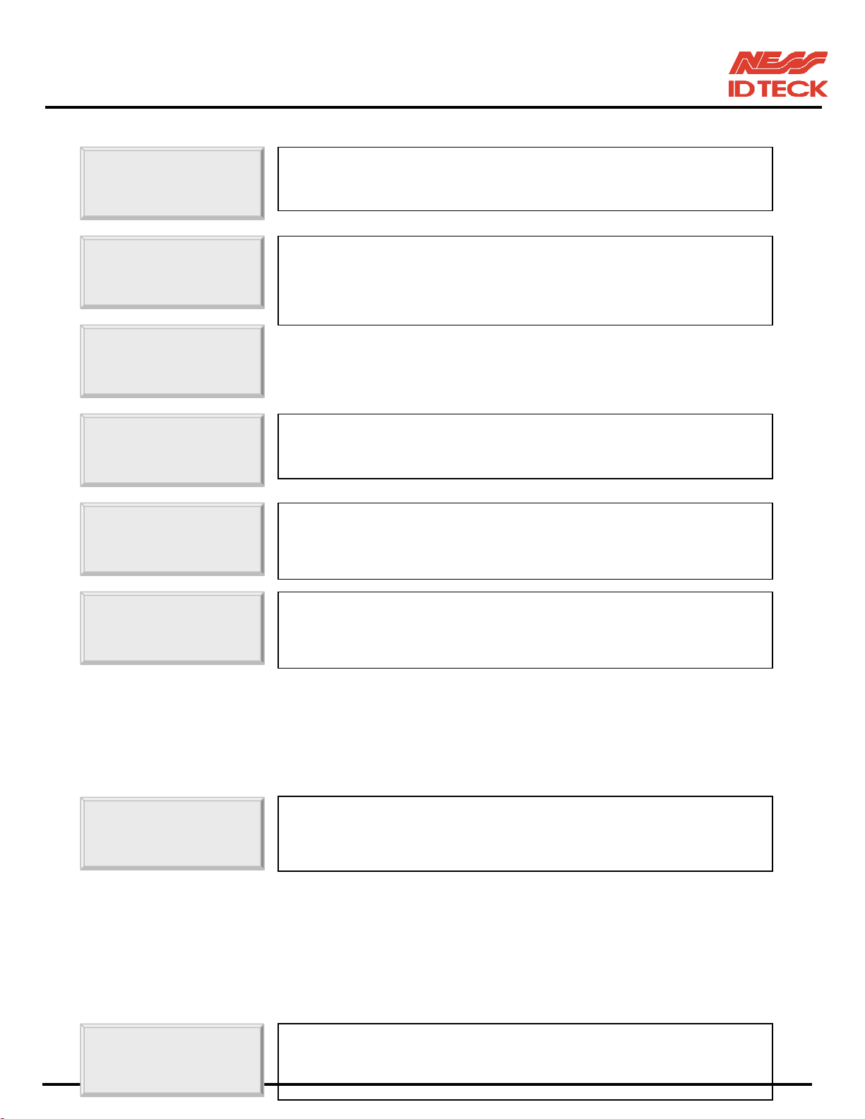
IDTeck – iTDC 2~4 DOOR ACCESS CONTROLLER
☞. If you want to see the list of registered User ID, press the <ENT>
ID LIST
ID[XXXXXXXX]
TA__TB__TC__TD
key in this menu.
☞. 8 digit User ID, 4 digit password and T/S for the readers are
displayed on the LCD, and you can scroll up and down the list by
pressing <4> and <6> keys. Press <ESC> key to return to the
MEMORY
☞. “MEMORY EMPTY” message will be displayed when there is
☞. “ID LIST TOP” message will be displayed first when the first
registered User ID is displayed on the LCD.
ID number of iTDC-SR is 10 digits decimal number.
10.3.4 REGISTERED ID COUNT
REG. ID COUNT
☞. “ID LIST BOTTOM” message will be displayed first when the
last registered User ID is displayed on the LCD.
☞. This menu displays the total number of registered User ID. It
automatically counts when you register or delete User ID. LCD
shows 12,345 User ID is now registered in the memory.
10.3.5 ID COUNT
☞. Press <ENT> key to change maximum ID Count.
ID COUNT
101-001 (iTDC), 101-002 (EIO88), 101-145 (iTDCSR) -56- Users Manual
Note! This must be set-up first before other set-up.
Please refer to section 8.5 ID COUNT SETTING.
Page 57
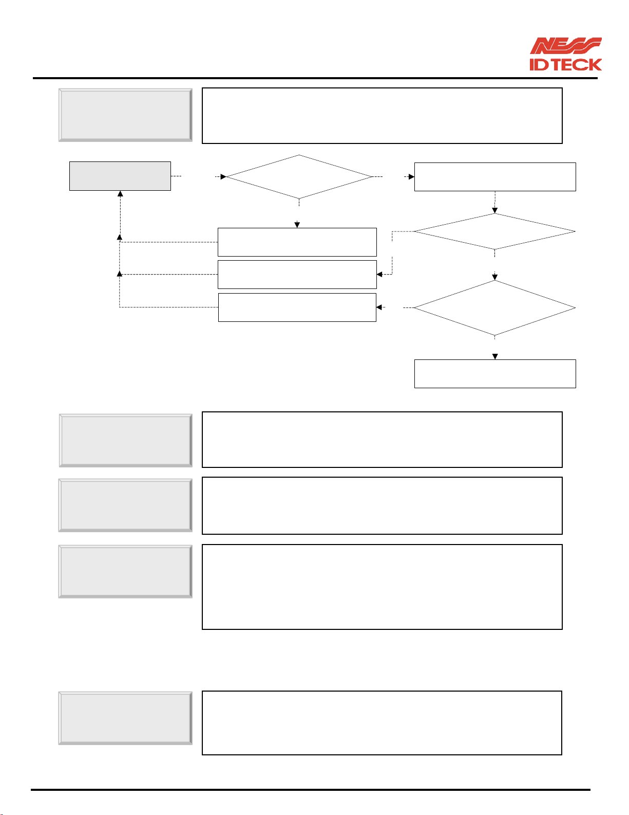
IDTeck – iTDC 2~4 DOOR ACCESS CONTROLLER
g
p
ENTER ID
ID COUNT
☞. Enter number from 1000 to 20000 in multiple of 1000 for the
maximum User ID count. Example: 1000, 2000, 5000, 10000,
ress <ENT> key.
EMPTY ?
NO
YES
NO
NO
ENTER NO. (4 ~ 5 digit)
ID COUNT VALID ?
YES
REGISTERED ID COUNT
< ENTER NO. ?
YES
COMPLETE
<ENT>
20000. Then
EVENT MEMORY
DISPLAY: EVENT MEMORY
NOT EMPTY
DISPLAY: INVALID COUNT
DISPLAY: ID TOTAL COUNT
WRONG !!!
EVENT MEMORY
ID TOTAL
10.3.6 STORED EVENT COUNT
EVENT COUNT
☞. LCD will display “Invalid Count” error message when you enter
the ID Count which is not multiple of 1,000 or the ID Count is
not in between 1,000 and 20,000.
☞. LCD will display “EVENT MEMORY NOT EMPTY!!!” error
message when you want to change ID Count and there are some
events still existin
in the Event Buffer.
☞. LCD will display “ID TOTAL COUNT Wrong !!!” error message
when you enter the less ID Count number than the number of
User ID registered in the memory.
Note! This must be set-up first before other set-up.
Please refer to section 8.3 DOOR SETTING.
☞. This menu displays the total number of event.
It automatically counts when you upload to PC. LCD shows
1,234 User ID is now registered in the memory
101-001 (iTDC), 101-002 (EIO88), 101-145 (iTDCSR) -57- Users Manual
Page 58
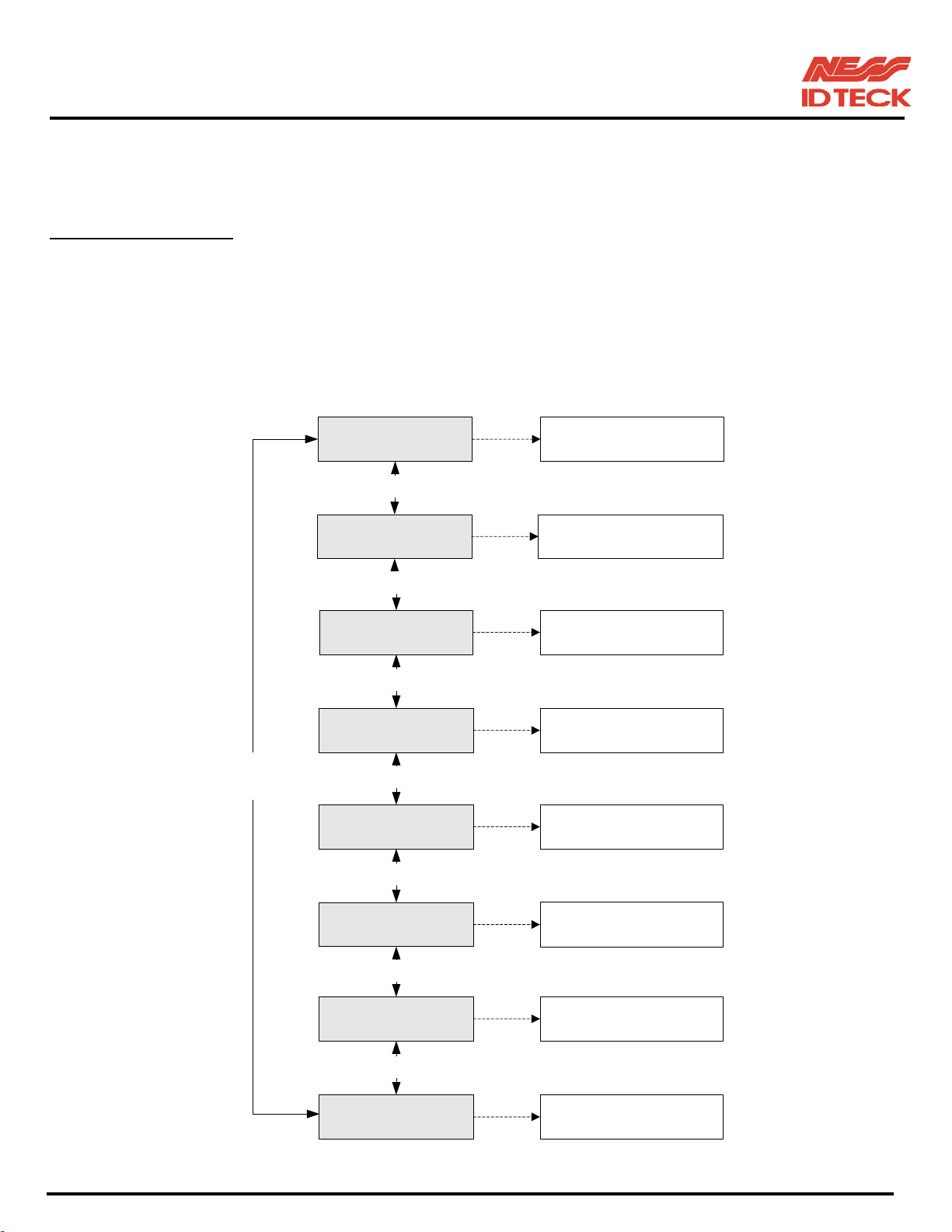
IDTeck – iTDC 2~4 DOOR ACCESS CONTROLLER
10.4 SETUP MENU F4
☞. On set-up menu F4, there are self-diagnosis functions to test the performances of the operations. To
test, press <ENT> key on the menu.
Searching
key<4> or <6>
VERSION
key<4> or <6>
SRAM TEST
key<4> or <6>
OUTPUT TEST
key<4> or <6>
LCD TEST
key<4> or <6>
KEYPAD TEST
key<4> or <6>
READER TEST READER TEST
DISPLAY CURRENT F/W
VERSION
SRAM TEST
OUTPUT TEST
LCD TEST
KEYPAD TEST
key<4> or <6>
INPUT TEST INPUT TEST
key<4> or <6>
COMM TEST
COMMUNICATION TEST
(RS-232)
101-001 (iTDC), 101-002 (EIO88), 101-145 (iTDCSR) -58- Users Manual
Page 59
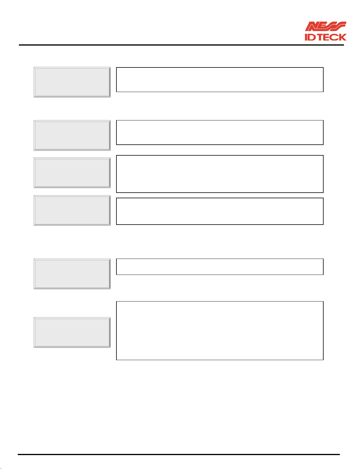
IDTeck – iTDC 2~4 DOOR ACCESS CONTROLLER
10.4.1 VERSION CHECK
VERSION
10.4.2 SRAM TEST
SRAM TEST
Memory fail!! 00
RAM test pass!!!
10.4.3 OUTPUTS TEST
☞. The version of the controller’s firmware is displayed on the LCD.
Press <4> or <6> key to look for other menus of set-up menu F4.
☞. To test the SRAM memory, press <ENT> key.
☞. If the SRAM has problems, LCD will show the memory block
number with Memory fail message. In this case, you have to
contact technical support. Press any key to return to the set-up
☞. If the SRAM is working properly then LCD will show RAM test
pass message. Press any key to return to the set-up menu.
OUTPUT
OUTPUT 8
☞. To test the outputs, press <ENT> key.
☞. The output test will be proceeding for each output twice On and
Off. The first 4 test is for output relays (Realy#1~Relay#4) so
you can hear the mechanical sound of relays and followed 3 test
is for TTL output test. The last test is for built-in buzzer test and
you can hear two beep sounds. Press any key to return to the setup menu.
101-001 (iTDC), 101-002 (EIO88), 101-145 (iTDCSR) -59- Users Manual
Page 60
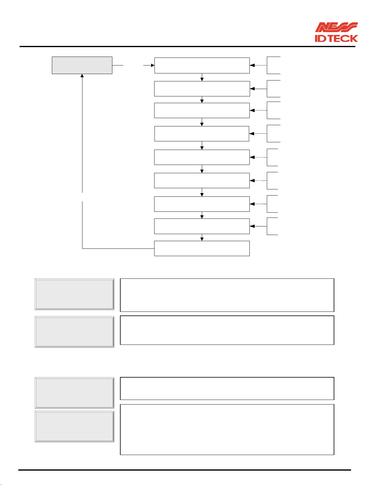
IDTeck – iTDC 2~4 DOOR ACCESS CONTROLLER
,
OUTPUT TEST
Enter any key
<ENT>
Relay 1 test
(Activated two times)
Relay 2 test
(Activated two times)
Relay 3 test
(Activated two times)
Relay 4 test
(Activated two times)
TTL Output 1 test
(Activated two times)
TTL Output 2 test
(Activated two times)
TTL Output 3 test
(Activated two times)
Buzzer Output test
(Activated two times)
This test is applicable to
Relay1 and LED.
This test is applicable to
Relay2 and LED.
This test is applicable to
Relay3 and LED.
This test is applicable to
Relay4 and LED.
This test is applicable to
TTL1. (0V - 5V)
This test is applicable to
TTL2. (0V - 5V)
This test is applicable to
TTL3. (0V - 5V)
This test is applicable to
Buzzer.
10.4.4 LCD TEST
LCD TEST
Last Update
10.4.5 KEYPAD TEST
KEYPAD TEST
Output test end
☞. Press <ENT> key to continue the test. LCD will display all
characters on the screen.
☞. When the test is done. LCD will show “Last Update Press any
key…” then press any key to return to the set-up menu.
☞. Press <ENT> key to start the keypad test.
☞. LCD will display “0123456789ABCDEF” on the bottom line of
LCD. Press each key from the keypad then the depressed key will
be disappeared from the LCD. Note that F1 key is “A”, F2 key is
“B”, F3 key is “C”, F4 key is “D”, ESC key is “E” and ENT key is
“F” on the screen. After the test is done
it returns to set-upmenu.
101-001 (iTDC), 101-002 (EIO88), 101-145 (iTDCSR) -60- Users Manual
Page 61
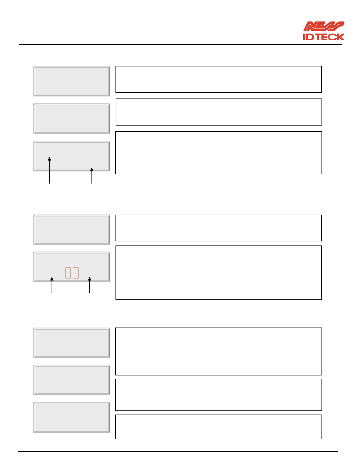
IDTeck – iTDC 2~4 DOOR ACCESS CONTROLLER
10.4.6 READER TEST
READER TEST
. Press <ENT> key for the reader test.
Scanning ...
☞. LCD will display “Scanning…” for reading the cards. Present the
☞. When the reader successfully read the card, LCD will display
Reader 1
Card # Reader #
10.4.7 INPUT AND DIP SWITCH TEST
INPUT TEST
INPUT TEST
DIP S/W
INPUT
☞. Press <ENT> key for the input test.
. The first 8 digits of the bottom line shows the status of the
10.4.8 COMMUNICATION TEST
card to one of the readers.
reader number and 8-digit card number on the LCD. Press
<ESC> key to return to the set-up menu.
ID number of iTDC-SR is 10 digit decimal number.
DIPswitch for communication ID setting and “1” indicates the
switch ON position and “0” indicates the switch OFF position. The
last 7 digits shows the input status and “0” indicates the input port
open circuit and “1” indicates the input port short to ground level.
Press <ESC> key to return to the set-up menu.
COMM TEST
TX data = 0
☞. Before this communication test,
RS232: Connect the RS232-RX and RS232-TX wires together.
RS-422: Connect the Rx (-) and TX (-), Rx (+) and TX (+) wires.
Note!! In case of RS-422 test, JP3, 4 disconnection and JP5, 6 short
☞. This test is a loop test and iTDC sends a character to TX port and
check whether the RX port receive the character or not. If you
have an error, please contact our service facility.
COMM test pass!!
☞. After the test is done, LCD will display “COMM test pass!!”
Press any key to return to the set-upmenu.
101-001 (iTDC), 101-002 (EIO88), 101-145 (iTDCSR) -61- Users Manual
Page 62
IDTeck – iTDC 2~4 DOOR ACCESS CONTROLLER
APPENDIX
A. THE RELATION BETWEEN INPUT AND OUTPUT (DEFAULT)
1. The relation between input and output (2Door set-up: iTDC Board Default)
Index No Relay#1 Relay#2 Relay#3 Relay#4 TTL#1 TTL#2 TTL#3
[1] Input #1 (Door1 Exit button)
[2] Input #2 (Door1 Contact SW) 00
[3] Input #3 (Door2 Exit button) 00 00
[4] Input #4 (Door2 Contact SW) 00 00 00
[5] Input #5 00 00 00 00 00 00 00
[6] Input #6 00 00 00 00 00 00 00
[7] Input #7 00 00 00 00 00 00 00
[8] EIO88 Input #1 00 00 00 00 00 00 00
[9] EIO88 Input #2 00 00 00 00 00 00 00
[10] EIO88 Input #3 00 00 00 00 00 00 00
[11] EIO88 Input #4 00 00 00 00 00 00 00
[12] EIO88 Input #5 00 00 00 00 00 00 00
[13] EIO88 Input #6 00 00 00 00 00 00 00
[14] EIO88 Input #7 00 00 00 00 00 00 00
[15] EIO88 Input #8 00 00 00 00 00 00 00
[16] DURESS MODE 1
03
03
00 00 00 00 00 00
03
00 00 00 00 00 00
00 00 00 00 00
03
00 00 00 00
03
00 00 00
[17] DURESS MODE 2
[18] DURESS MODE 3 00 00
[19] DURESS MODE 4 00 00
[20] OUTPUT Time Schedule 00 00 00 00 00 00 00
[21] INPUT Time Schedule 00 00 00 00 00 00 00
[22] INPUT Type
Default output setting values of EIO88 Relay#1 ~ Relay#8 are all “00”.
INPUT Type: “00”= NC, “01”= NO
03
01 01 01 01 01 01 01
00 00 00 00 00 00
03
03
00 00 00 00
00 00 00 00
101-001 (iTDC), 101-002 (EIO88), 101-145 (iTDCSR) -62- Users Manual
Page 63
IDTeck – iTDC 2~4 DOOR ACCESS CONTROLLER
2. The relation between input and output (3Door set-up: iTDC Board Default)
Index No Relay#1 Relay#2 Relay#3 Relay#4 TTL#1 TTL#2 TTL#3
[1] Input #1 (Door1 Exit button)
03
[2] Input #2 (Door1 Contact SW) 00
00 00 00 00 00 00
03
00 00 00 00 00
[3] Input #3 00 00 00 00 00 00 00
[4] Input #4 00 00 00 00 00 00 00
[5] Input #5 00 00 00 00 00 00 00
[6] Input #6 00 00 00 00 00 00 00
[7] Input #7 00 00 00 00 00 00 00
[8] EIO88 Input #1 (Door2 Exit) 00 00 00 00 00 00 00
[9] EIO88 Input #2 (Door2 Contact) 00 00 00 00 00 00 00
[10] EIO88 Input #3 (Door3 Exit) 00 00 00 00 00 00 00
[11] EIO88 Input #4 (Door3 Contact) 00 00 00 00 00 00 00
[12] EIO88 Input #5 00 00 00 00 00 00 00
[13] EIO88 Input #6 00 00 00 00 00 00 00
[14] EIO88 Input #7 00 00 00 00 00 00 00
[15] EIO88 Input #8 00 00 00 00 00 00 00
[16] DURESS MODE 1
03
00 00 00 00 00 00
[17] DURESS MODE 2
03
00 00 00 00 00 00
[18] DURESS MODE 3 00 00 00 00 00 00 00
[19] DURESS MODE 4 00 00 00 00 00 00 00
[20] OUTPUT Time Schedule 00 00 00 00 00 00 00
[21] INPUT Time Schedule 00 00 00 00 00 00 00
[22] INPUT Type
01 01 01 01 01 01 01
INPUT Type: “00”= NC, “01”= NO
101-001 (iTDC), 101-002 (EIO88), 101-145 (iTDCSR) -63- Users Manual
Page 64

IDTeck – iTDC 2~4 DOOR ACCESS CONTROLLER
3. The relation between input and output (3Door set-up: EIO88 Extension I/O Board Default)
Index No
[1] Input #1 (Door1 Exit button) 00 00 00 00 00 00 00 00
[2] Input #2 (Door1 Contact SW) 00 00 00 00 00 00 00 00
[3] Input #3 00 00 00 00 00 00 00 00
[4] Input #4 00 00 00 00 00 00 00 00
[5] Input #5 00 00 00 00 00 00 00 00
[6] Input #6 00 00 00 00 00 00 00 00
[7] Input #7 00 00 00 00 00 00 00 00
[8] EIO88 Input #1 (Door2 Exit)
[9] EIO88 Input #2 (Door2 Contact) 00
[10] EIO88 Input #3 (Door3 Exit) 00 00
[11] EIO88 Input #4 (Door3 Contact) 00 00 00
[12] EIO88 Input #5 00 00 00 00 00 00 00 00
[13] EIO88 Input #6 00 00 00 00 00 00 00 00
Relay#1 Relay#2 Relay#3 Relay#4 Relay#5 Relay#6 Relay#7 Relay#8
03
00 00 00 00 00 00 00
03
00 00 00 00 00 00
03
00 00 00 00 00
03
00 00 00 00
[14] EIO88 Input #7 00 00 00 00 00 00 00 00
[15] EIO88 Input #8 00 00 00 00 00 00 00 00
[16] DURESS MODE 1 00 00 00 00 00 00 00 00
[17] DURESS MODE 2 00 00 00 00 00 00 00 00
[18] DURESS MODE 3
[19] DURESS MODE 4 00 00
[20] OUTPUT TIME SCHEDULE 00 00 00 00 00 00 00 00
[21] INPUT TIME SCHEDULE 00 00 00 00 00 00 00 00
[22] INPUT TYPE
03
01 01 01 01 01 01 01 01
00 00 00 00 00 00 00
03
00 00 00 00 00
INPUT Type: “00”= NC, “01”= NO
101-001 (iTDC), 101-002 (EIO88), 101-145 (iTDCSR) -64- Users Manual
Page 65
IDTeck – iTDC 2~4 DOOR ACCESS CONTROLLER
4. The relation between input and output (4Door set-up: iTDC Board Default)
Index No Relay#1 Relay#2 Relay#3 Relay#4 TTL#1 TTL#2 TTL#3
[1] Input #1 (Door1 Exit Button)
[2] Input #2 (Door1 Contact SW) 00
[3] Input #3 (Door2 Exit Button) 00 00
[4] Input #4 (Door2 Contact SW) 00 00 00
[5] Input #5 00 00 00 00 00 00 00
[6] Input #6 00 00 00 00 00 00 00
[7] Input #7 00 00 00 00 00 00 00
[8] EIO88 Input #1 (Door3 Exit) 00 00 00 00 00 00 00
[9] EIO88 Input #2 (Door3 Contact) 00 00 00 00 00 00 00
[10] EIO88 Input #3 (Door4 Exit) 00 00 00 00 00 00 00
[11] EIO88 Input #4 (Door4 Contact) 00 00 00 00 00 00 00
[12] EIO88 Input #5 00 00 00 00 00 00 00
[13] EIO88 Input #6 00 00 00 00 00 00 00
[14] EIO88 Input #7 00 00 00 00 00 00 00
[15] EIO88 Input #8 00 00 00 00 00 00 00
[16] DURESS MODE 1
03
03
00 00 00 00 00 00
03
00 00 00 00 00 00
00 00 00 00 00
03
00 00 00 00
03
00 00 00
[17] DURESS MODE 2 00 00
[18] DURESS MODE 3 00 00 00 00 00 00 00
[19] DURESS MODE 4 00 00 00 00 00 00 00
[20] OUTPUT Time Schedule 00 00 00 00 00 00 00
[21] INPUT Time Schedule 00 00 00 00 00 00 00
[22] INPUT Type
INPUT Type: “00”= NC, “01”= NO
01 01 01 01 01 01 01
03
00 00 00 00
101-001 (iTDC), 101-002 (EIO88), 101-145 (iTDCSR) -65- Users Manual
Page 66

IDTeck – iTDC 2~4 DOOR ACCESS CONTROLLER
5. The relation between input and output (4Door set-up: EIO88 Default)
Index No
Relay#1 Relay#2 Relay#3 Relay#4 Relay#5 Relay#6 Relay#7 Relay#8
[1] Input #1 (Door1 Exit Button) 00 00 00 00 00 00 00 00
[2] Input #2 (Door1 Contact SW) 00 00 00 00 00 00 00 00
[3] Input #3 (Door2 Exit Button) 00 00 00 00 00 00 00 00
[4] Input #4 (Door3 Contact SW) 00 00 00 00 00 00 00 00
[5] Input #5 00 00 00 00 00 00 00 00
[6] Input #6 00 00 00 00 00 00 00 00
[7] Input #7 00 00 00 00 00 00 00 00
[8] EIO88 Input #1 (Door3 Exit)
03
[9] EIO88 Input #2 (Door3 Contact) 00
[10] EIO88 Input #3 (Door4 Exit) 00 00
[11] EIO88 Input #4 (Door4 Contact) 00 00 00
00 00 00 00 00 00 00
03
00 00 00 00 00 00
03
00 00 00 00 00
03
00 00 00 00
[12] EIO88 Input #5 00 00 00 00 00 00 00 00
[13] EIO88 Input #6 00 00 00 00 00 00 00 00
[14] EIO88 Input #7 00 00 00 00 00 00 00 00
[15] EIO88 Input #8 00 00 00 00 00 00 00 00
[16] DURESS MODE 1 00 00 00 00 00 00 00 00
[17] DURESS MODE 2 00 00 00 00 00 00 00 00
[18] DURESS MODE 3
03
[19] DURESS MODE 4 00 00
00 00 00 00 00 00 00
03
00 00 00 00 00
[20] OUTPUT TIME SCHEDULE 00 00 00 00 00 00 00 00
[21] INPUT TIME SCHEDULE 00 00 00 00 00 00 00 00
[22] INPUT TYPE
01 01 01 01 01 01 01 01
Input type: 00- NC, 01- NO
101-001 (iTDC), 101-002 (EIO88), 101-145 (iTDCSR) -66- Users Manual
Page 67
IDTeck – iTDC 2~4 DOOR ACCESS CONTROLLER
6. Factory settings on the outputs regarding access attempts (2Door set-up: iTDC Board Default)
[1] Reader#1 ID OK
[2] Reader#1 ID Error 00
[3] Reader#1 ID T/S Error 00
[4] Reader#1 APB Error 00
[5] Reader#2 ID OK
[6] Reader#2 ID Error 00
[7] Reader#2 ID T/S Error 00
[8] Reader#2 APB Error 00
[9] Reader#3 ID OK 00 00
[10] Reader#3 ID Error 00 00 00
[11] Reader#3 ID T/S Error 00 00 00
[12] Reader#3 APB Error 00 00 00
[13] Reader#4 ID OK 00 00
[14] Reader#4 ID Error 00 00 00
[15] Reader#4 ID T/S Error 00 00 00
[16] Reader#4 APB Error 00 00 00
Index No Relay#1 Relay#2 Relay#3 Relay#4 TTL#1 TTL#2 TTL#3
03
03
00 00 00 00 00 00
03
03
03
00 00 00 00 00
00 00 00 00 00
00 00 00 00 00
00 00 00 00 00 00
03
03
03
00 00 00 00 00
00 00 00 00 00
00 00 00 00 00
03
03
00 00 00 00
03
03
03
00 00 00
00 00 00
00 00 00
00 00 00 00
03
03
03
00 00 00
00 00 00
00 00 00
Factory set values of the EIO88 Expansion I/O board are all ‘00’s.
101-001 (iTDC), 101-002 (EIO88), 101-145 (iTDCSR) -67- Users Manual
Page 68
IDTeck – iTDC 2~4 DOOR ACCESS CONTROLLER
7. Factory settings on the outputs regarding access attempts (3Door set-up: iTDC Board Default)
[1] Reader#1 ID OK
[2] Reader#1 ID Error 00
[3] Reader#1 ID T/S Error 00
[4] Reader#1 APB Error 00
[5] Reader#2 ID OK
[6] Reader#2 ID Error 00
[7] Reader#2 ID T/S Error 00
[8] Reader#2 APB Error 00
Index No Relay#1 Relay#2 Relay#3 Relay#4 TTL#1 TTL#2 TTL#3
03
03
00 00 00 00 00 00
03
03
03
00 00 00 00 00
00 00 00 00 00
00 00 00 00 00
00 00 00 00 00 00
03
03
03
00 00 00 00 00
00 00 00 00 00
00 00 00 00 00
[9] Reader#3 ID OK 00 00 00 00 00 00 00
[10] Reader#3 ID Error 00 00 00 00 00 00 00
[11] Reader#3 ID T/S Error 00 00 00 00 00 00 00
[12] Reader#3 APB Error 00 00 00 00 00 00 00
[13] Reader#4 ID OK 00 00 00 00 00 00 00
[14] Reader#4 ID Error 00 00 00 00 00 00 00
[15] Reader#4 ID T/S Error 00 00 00 00 00 00 00
[16] Reader#4 APB Error 00 00 00 00 00 00 00
101-001 (iTDC), 101-002 (EIO88), 101-145 (iTDCSR) -68- Users Manual
Page 69
IDTeck – iTDC 2~4 DOOR ACCESS CONTROLLER
8. Factory settings on the outputs regarding access attempts (3Door set-up: EIO88 Default)
Index No
Relay#1 Relay#2 Relay#3 Relay#4 Relay#5 Relay#6 Relay#7 Relay#8
[1] Reader#1 ID OK 00 00 00 00 00 00 00 00
[2] Reader#1 ID Error 00 00 00 00 00 00 00 00
[3] Reader#1 ID T/S Error 00 00 00 00 00 00 00 00
[4] Reader#1 APB Error 00 00 00 00 00 00 00 00
[5] Reader#2 ID OK 00 00 00 00 00 00 00 00
[6] Reader#2 ID Error 00 00 00 00 00 00 00 00
[7] Reader#2 ID T/S Error 00 00 00 00 00 00 00 00
[8] Reader#2 APB Error 00 00 00 00 00 00 00 00
[9] Reader#3 ID OK
03
[10] Reader#3 ID Error 00
[11] Reader#3 ID T/S Error 00
[12] Reader#3 APB Error 00
[13] Reader#4 ID OK 00 00
[14] Reader#4 ID Error 00 00 00
[15] Reader#4 ID T/S Error 00 00 00
[16] Reader#4 APB Error 00 00 00
00 00 00 00 00 00 00
03
03
03
00 00 00 00 00 00
00 00 00 00 00 00
00 00 00 00 00 00
03
00 00 00 00 00
03
03
03
00 00 00 00
00 00 00 00
00 00 00 00
101-001 (iTDC), 101-002 (EIO88), 101-145 (iTDCSR) -69- Users Manual
Page 70
IDTeck – iTDC 2~4 DOOR ACCESS CONTROLLER
9. Factory settings on the outputs regarding access attempts (4Door set-up: iTDC Board Default)
[1] Reader#1 ID OK
[2] Reader#1 ID Error 00
[3] Reader#1 ID T/S Error 00
[4] Reader#1 APB Error 00
[5] Reader#2 ID OK 00 00
[6] Reader#2 ID Error 00 00 00
[7] Reader#2 ID T/S Error 00 00 00
[8] Reader#2 APB Error 00 00 00
[9] Reader#3 ID OK 00 00 00 00 00 00 00
[10] Reader#3 ID Error 00 00 00 00 00 00 00
[11] Reader#3 ID T/S Error 00 00 00 00 00 00 00
[12] Reader#3 APB Error 00 00 00 00 00 00 00
[13] Reader#4 ID OK 00 00 00 00 00 00 00
[14] Reader#4 ID Error 00 00 00 00 00 00 00
[15] Reader#4 ID T/S Error 00 00 00 00 00 00 00
Index No Relay#1 Relay#2 Relay#3 Relay#4 TTL#1 TTL#2 TTL#3
03
00 00 00 00 00 00
03
03
03
00 00 00 00 00
00 00 00 00 00
00 00 00 00 00
03
00 00 00 00
03
03
03
00 00 00
00 00 00
00 00 00
[16] Reader#4 APB Error 00 00 00 00 00 00 00
101-001 (iTDC), 101-002 (EIO88), 101-145 (iTDCSR) -70- Users Manual
Page 71
IDTeck – iTDC 2~4 DOOR ACCESS CONTROLLER
10.
Factory settings on the outputs regarding access attempts (4Door set-up: EIO88 Default)
Index No
Relay#1 Relay#2 Relay#3 Relay#4 Relay#5 Relay#6 Relay#7 Relay#8
[1] Reader#1 ID OK 00 00 00 00 00 00 00 00
[2] Reader#1 ID Error 00 00 00 00 00 00 00 00
[3] Reader#1 ID T/S Error 00 00 00 00 00 00 00 00
[4] Reader#1 APB Error 00 00 00 00 00 00 00 00
[5] Reader#2 ID OK 00 00 00 00 00 00 00 00
[6] Reader#2 ID Error 00 00 00 00 00 00 00 00
[7] Reader#2 ID T/S Error 00 00 00 00 00 00 00 00
[8] Reader#2 APB Error 00 00 00 00 00 00 00 00
[9] Reader#3 ID OK
03
[10] Reader#3 ID Error 00
[11] Reader#3 ID T/S Error 00
[12] Reader#3 APB Error 00
[13] Reader#4 ID OK 00 00
[14] Reader#4 ID Error 00 00 00
[15] Reader#4 ID T/S Error 00 00 00
[16] Reader#4 APB Error 00 00 00
00 00 00 00 00 00 00
03
03
03
00 00 00 00 00 00
00 00 00 00 00 00
00 00 00 00 00 00
03
00 00 00 00 00
03
03
03
00 00 00 00
00 00 00 00
00 00 00 00
101-001 (iTDC), 101-002 (EIO88), 101-145 (iTDCSR) -71- Users Manual
Page 72

IDTeck – iTDC 2~4 DOOR ACCESS CONTROLLER
B. TROUBLE SHOOTING
☞ Broken or abnormal letters show on the LCD, when powered on.
Cause
Solution
SRAM backup battery problem or LCD module problem.
1. Initialise the controller and set-up the date and time on SETUP MENU F2->SYS INITIALIZE
and SETUP MENU F2->TIME SETTING.
2. If you still have problem, please contact a designated service centre.
☞
Can I set the controller to operate in RF only mode for one card and in RF+P/W mode for another?
Cause N/A
Solution 1. Do not mix the working mode for one Reader.
2. But you can set one reader to operate in RF only mode and another one in RF+P/W mode.
☞
The Set-up mode suddenly goes back to the Normal-operating mode.
Cause Time out error
Solution 1. In the Set-up mode, it is programmed to do so when there is no key-in or reading card within
20 seconds.
☞
A valid card became unregistered after batch-downloading IDs from PC.
Cause Wrong procedure during download, or a component defect.
Solution 1. The card ID might be registered only to the controller and not registered in PC. The process of
downloading IDs, iTDC first erase the ID memory of the unit, therefore if the IDs from the PC
didn’t contain the card ID, this can happen.
2. Check whether the card ID is registered in PC
3. If not, please register the number and try downloading again.
4. If the trouble remains after the procedure above, contact a designated service centre.
101-001 (iTDC), 101-002 (EIO88), 101-145 (iTDCSR) -72- Users Manual
Page 73

IDTeck – iTDC 2~4 DOOR ACCESS CONTROLLER
☞
Doesn’t enter the Set-up Mode after entering the Master ID “00000000”.
Cause The Master ID might be changed or components are defective.
Solution 1. Try changing the Master ID through the application S/W. (It’ll be changed to “00000000”.)
- Note that the Master ID for iTDC-SR is 10 times <0>, “0000000000”.
2. When it is not feasible, initialise the unit as followings.
- Press the two System Initialisation Switches simultaneously while power is on.
- Wait until the message ‘Initialise END Turn OFF Power…’ appears on the LCD and turn it
off and on again. Try entering the Set-up mode.
- Note that all the value will be set to default, including the IDs after initialising.
3. If the trouble remains after the procedure above, contact a designated service centre.
☞
No problem with accessing by cards, but cannot access with the PIN input.
Cause An error in Set-up or possible component defect.
Solution 1. Check whether a beep sound is generated when you press a key.
When it is, the problem may be an error in set-up. Precede followings.
- Enter the Master ID (“00000000” default) to enter the Set-up mode.
(Note that the Master ID for iTDC-SR is 10 times <0>, “0000000000”.)
- Press <F1> key.
- ‘READER 1 MODE’ will appear on the LCD, then use the key <6> to choose ‘READER1
KEY IN’, ‘READER2 KEY IN’, ‘READER3 KEY IN’, or ‘READER4 KEY IN’ and select
‘Enable’ as wanted.
2. When there is no beep sound or already enabled Key-in functions, contact a designated service
centre.
101-001 (iTDC), 101-002 (EIO88), 101-145 (iTDCSR) -73- Users Manual
Page 74

IDTeck – iTDC 2~4 DOOR ACCESS CONTROLLER
☞
The reader seems to read cards, but the controller does not respond or does not respond properly,
such as displaying wrong card numbers in the reader test mode.
Cause Reader defect, wiring error between the reader and the controller, or the electric noises around.
Solution 1. Be sure that the reader reads the card ID when you present a card.
2. Be sure that the reader format is correct. 26bit Wiegand or 34bit Wiegand for iTDC-SR
3. Check the wiring between the reader and iTDC.
- Check the wires of Wiegand data lines D0 and D1, which is connected correctly.
- Connect the controller ground to the ground wire of the reader and it is recommended to
connect them to an earth ground.
4. Using oscilloscope, check the shape of signals from the reader at the controller’s side.
When noises are shown on the signals, it is recommended to use shielded wires and the
unused wires to the common ground. You can use repeaters, also.
5. Check the maximum cable length, which may be indicated on the reader manual.
6. If the trouble remains after the procedure above, contact a designated service centre.
101-001 (iTDC), 101-002 (EIO88), 101-145 (iTDCSR) -74- Users Manual
Page 75
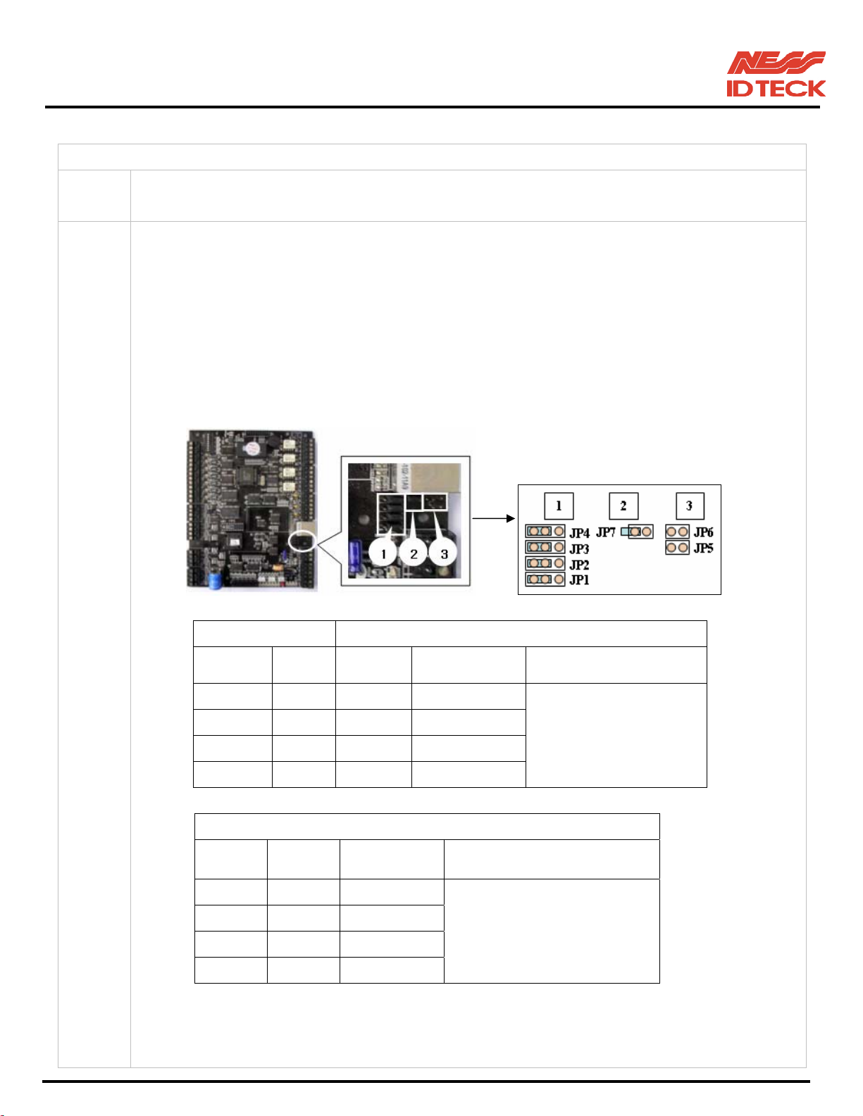
IDTeck – iTDC 2~4 DOOR ACCESS CONTROLLER
☞
The controller does not communicate with PC.
Cause Defective cable is used, errors in wiring, an error in setting COMM ID of the controller, or
damage on the communication port (either on PC side or on the controller side).
Solution 1. Please, check the settings of the application S/W and the controller.
- Check the controller’s COMM ID is listed on the application S/W.
- Set the different COMM ID when two or more controllers are installed.
- Check the communication speed (9600bps default) is the same as the setting on the S/W.
- Make sure that the PC’s COM port is set correctly on the S/W.
- The parameters at the S/W should be set as follows.
Parity bit: NONE
Data bit: 8bit
Stop bit: 1bit
2. RS_422 Jumper
2. Check the line connection for communication.
RS232 RS422 (mono)
iTDC PC iTDC
TX port TX RX(-) TX(-)
RX port RX RX(+) TX(+)
GND GND TX(-) RX(-)
TX(+) RX(+)
RS422/232
Converter
The RS232 cable from
the converter
PC
RS422 (Multi Drop)
iTDC
iTDC
RX(-) RX(-) TX(-)
RX(+) RX(+) TX(+)
RS422/232
Converter
PC
The RS232 cable from
the converter
TX(-) TX(-) RX(-)
TX(+) TX(+) RX(+)
3. In case of setting RS422 communication, recommend to use line-end resistors of 120 Ohm
between the RX (+) and RX (-) lines and between the TX (+) and TX (-) lines, and apply the
same resistors to the converter RS422 lines. Consult a service centre or an electric
101-001 (iTDC), 101-002 (EIO88), 101-145 (iTDCSR) -75- Users Manual
Page 76

IDTeck – iTDC 2~4 DOOR ACCESS CONTROLLER
technician if you cannot be sure how to do it.
4. When a multi-drop communication doesn’t work, test one-by-one communication first.
5. If the trouble remains after the procedure above, contact a designated service centre.
101-001 (iTDC), 101-002 (EIO88), 101-145 (iTDCSR) -76- Users Manual
Page 77

IDTeck – iTDC 2~4 DOOR ACCESS CONTROLLER
FCC REGISTRATION INFORMATION
FCC REQUIREMENTS PART 15
Caution: Any changes or modifications in construction of this device, which are not expressly approved
by the manufacturer for compliance, could void the user's authority to operate the equipment.
NOTE: This device complies with Part 15 of the FCC Rules.
Operation is subject to the following two conditions;
1. This device may not cause harmful interference, and
2. This device must accept any interference received, including interference that may cause undesired
operation.
This equipment has been tested and found to comply with the limits for a Class A Digital Device,
pursuant to Part 15 of the FCC Rules. These limits are designed to this equipment generates, uses, and
can radiate radio frequency energy and, if not installed and used in accordance with the instructions, may
cause harmful interference to radio communications.
However, there is no guarantee that interference will not occur in a particular installation. If this
equipment does cause harmful interference to radio or television reception, which can be determined by
turning the radio or television off and on, the user is encouraged to try to correct interference by one or
more of the following measures.
1. Reorient or relocate the receiving antenna.
2. Increase the separation between the equipment and receiver.
3. Connect the equipment into an outlet on another circuit.
4. Consult the dealer or an experienced radio/TV technician for help.
101-001 (iTDC), 101-002 (EIO88), 101-145 (iTDCSR) -77- Users Manual
Page 78

IDTeck – iTDC 2~4 DOOR ACCESS CONTROLLER
CONTACTS
Ness Security Products Pty Ltd
ABN 28 069 984 372
Head Office – NSW:
4 / 167 Prospect Hwy
Seven Hills, NSW, 2147 – Australia
Ph +61 2 8825 9222
Fax + 61 2 9674 2520
www.ness.com.au
email:[email protected]
NSW:
4 / 167 Prospect Hwy
Seven Hills, NSW, 2147
Ph (02) 8825 9222
Fax (02) 9674 2520
QLD:
Unit 3A / 471 Lytton Road
Morningside, Qld, 4170
Ph (07) 3399 4910
Fax (07) 3217 9711
Vic:
24 Terracotta Drive
Blackburn, Vic, 3130
Ph (03) 9875 6400
Fax (03) 9875 6422
W.A:
Unit 1, 567 Newcastle Street
Perth, W.A., 6000
Ph (08) 9328 2511
Fax (08) 9227 7073
101-001 (iTDC), 101-002 (EIO88), 101-145 (iTDCSR) -78- Users Manual
Page 79

IDTeck – iTDC 2~4 DOOR ACCESS CONTROLLER
NOTES
101-001 (iTDC), 101-002 (EIO88), 101-145 (iTDCSR) -79- Users Manual
Page 80

IDTeck – iTDC 2~4 DOOR ACCESS CONTROLLER
101-001 (iTDC), 101-002 (EIO88), 101-145 (iTDCSR) -80- Users Manual
 Loading...