

Page 1
ViVOpay
™
VP5300
User Manual
80152500-001 Rev. A
Page 2

ViVOpay VP5300 User Manual
Copyright
Copyright
ID TECH
10721 Walker Street
Cypress, CA 90630
USA
This document, as well as the hardware and software it describes, is furnished under license
and may only be used in accordance with the terms of such license. The content of this paper
is furnished for informational use, subject to change without notice, and not to be construed
as a commitment by ID TECH. ID TECH assumes no responsibility or liability for any errors or
inaccuracies that may appear in this document.
Except as permitted by such license, no part of this publication may be reproduced or
transmitted by electronic, mechanical, recorded, or any other method, or translated into
another language or language form without the express written consent of ID TECH. ID
TECH is a registered trademark of International Technologies and Systems Corporation.
ViVOpay and Value through Innovation are trademarks of International Technologies and
Systems Corporation. Other trademarks are the property of the respective owner.
Warranty Disclaimer: The services and hardware are provided "as is" and "as-available," and
the use of these services and hardware are at the user’s own risk. ID TECH does not make, and
hereby disclaims, any and all other express or implied warranties, including, but not limited to
warranties of merchantability, title, fitness for a particular purpose, and any warranties arising
from any course of dealing, usage, or trade practice. ID TECH does not warrant that the
services or hardware will be uninterrupted, error-free, or completely secure.
2017, International Technologies and Systems Corporation. All rights reserved.
2
Page 3
ViVOpay VP5300 User Manual
Caution:
The ViVOpay
VP5300
should be mounted 1
-
2 feet away from ot
her
Caution:
Danger of Explosion if battery is incorrectly replaced. Replace only with
Warning:
Avoid close proximity to radio transmitters which may reduce the ability
FCC Regulatory Compliance
Notices Class B Equipment
This equipment has been tested and found to comply with the limits for a Class B digital device
pursuant to Part 15 of the FCC Rules. These limits are designed to provide reasonable protection
against harmful interference in a residential installation. This equipment generates, uses, and can
radiate radio frequency energy and, if not installed and used in accordance with the instructions,
may cause harmful interference to radio communications. However, there is no guarantee that
interference will not occur in a particular installation. This device complies with part 15 of the FCC
rules. Operation is subject to two conditions: (1) This device may not cause harmful interference,
and (2) this device must accept any interference received, including interference that may cause
undesired operation.
If this equipment does cause harmful interference to radio or television reception, which can be
determined by turning the equipment off and on, the user is encouraged to try and correct the
interference by one or more of the following measures:
•
Reorient or relocate the receiving antenna.
•
Increase the separation between the equipment and the receiver.
•
Connect the equipment into an outlet on a circuit different from that to which the receiver is
connected.
•
Consult the dealer or an experienced radio/TV technician for help.
•
Changes or modifications to the ViVOpay VP5300 not expressly approved by ID TECH could
void the user's authority to operate the ViVOpay VP5300.
IC Compliance Warning
Operation is subject to two conditions: (1) This device may not cause harmful interference, and
(2) this device must accept any interference received, including interference that may cause
undesired operation.
Cautions and Warnings
ViVOpay VP5300 units. Can be adjusted based on lane setup.
same or equivalent type recommended by the manufacturer. Discard used
batteries according to the manufacturer’s instructions.
of the reader.
3
Page 4

ViVOpay VP5300 User Manual
Table of Contents
1. Overview
1.1
1.2
1.3
1.4
1.5
1.6
1.7
2. VP5300 3-View Drawing
3. VP5300 NFC Antenna 3-View
4. VP5300 Installation
4.1
4.2
4.3
Flush-Mounting the Antenna ................................................................................. 18
Attaching the Cables from the Antenna to the VP5300 ............................................. 18
4.4
4.5
4.6
4.7
Front LED Status .................................................................................................. 22
Diagnostic LED Status .......................................................................................... 22
4.8
Presenting Cards or NFC Phones ......................................................................... 24
5. Installation Points
6. RF Interference
7. Firmware Upgrade
Preparation ........................................................................................................... 26
8. Troubleshooting
.................................................................................................................. 5
Features .......................................................................................................... 7
ViVOpay VP5300: Approvals ........................................................................... 9
ViVOpay VP5300: Firmware ............................................................................ 9
ViVOpay VP5300: Physical/Mechanical Characteristics ................................ 11
ViVOpay VP5300: Environmental Characteristics .......................................... 12
ViVOpay 5300: Durability and Reliability Specs ............................................. 12
ViVOpay VP5300 Contactless Specifications ................................................ 12
.......................................................................................... 13
................................................................................... 14
................................................................................................. 15
Parts List ....................................................................................................... 15
Installation of Reader..................................................................................... 15
Mounting the ViVOpay VP5300 External NFC Antenna ................................. 16
Connecting to Power ..................................................................................... 19
Connecting to the Data Port .......................................................................... 19
Engaging the Removal Detection Switch for Testing ..................................... 21
LED Management ......................................................................................... 22
Using the ViVOpay VP5300 to Make a Purchase .......................................... 24
................................................................................................... 25
....................................................................................................... 25
.................................................................................................. 26
..................................................................................................... 29
4
Page 5

ViVOpay VP5300 User Manual
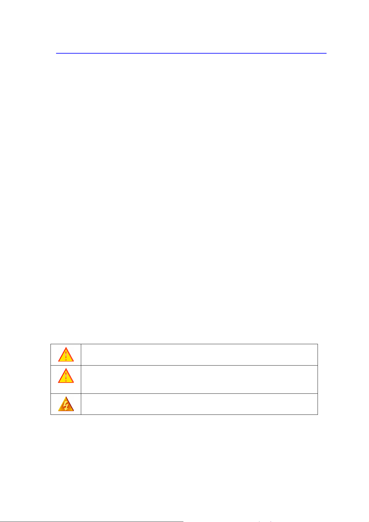
1. Overview
ID TECH's ViVOpay VP5300 is a compact, ruggedized credit card reader designed to support MSR
(magstripe) and contact EMV, plus contactless EMV (when the device is mated with the
VP5300’s NFC antenna).
The ViVOpay VP5300 is designed to deliver MSR, EMV, and NFC (contactless) payment
acceptance with SRED security and reliability, in unattended payment scenarios, such as Parking,
Fueling, ATM, Ticketing, and Payment Kiosks. When paired with the ID TECH SmartPIN L100 PCIcertified PIN pad, and the optional NFC antenna, all payment options from Chip-PIN to
NFC/mobile wallet solutions can be accepted.
VP5300 leads the industry in low power consumption and ruggedness, with its metal bezel and
IK10 and IP65 ratings to ensure long life in demanding conditions. VP5300 is certified to the latest
payment standards of EMV (Level 1 and Level 2) and PCI (5.x), and offers easy integration of
payments into self-serve kiosk and unattended environments.
The VP5300
VP5300 NFC Antenna
5
Page 6

ViVOpay VP5300 User Manual
Model Number
Description
SPTP2
-
988-33-2C-0C
Outdoor hybrid insert reader, metal bezel, 2
SPTP2
-
988-33-2CD-0C Same as above but with Demo Key injected, for
Model Number
Description
8015
2210
-
001 USB cable
80152211
-
001 RS-232 cable
140-2035
-00
Power supply, USA plug, 9VDC, 1.0A; 9
.0-26.
4
Model Number
Description
ID-80152002
-
001 Antenna
NFC Antenna, silver overlay
, with RJ
-
45 (male)
ID-80152002
-
002 Ante
nna NFC Antenna, black overlay
, with RJ
-
45 (male)
VP5300 PCI/EMV Certified Insert Reader
SAM, TDES, Card Present switch, Contactless
controller module
development and testing.
Optional Accessories
VAC input
NFC Antenna
coupling.
coupling.
The ViVOpay VP5300 supports USB and serial (RS-232) host communication using the command
protocol defined in the NEO Interface Developers Guide. This comprehensive guide describes all
of the firmware commands and other features available in ID TECH's NEO-series devices; it is the
authoritative source for technical information of interest to systems integrators. (Contact your ID
TECH representative to obtain a copy of this guide, which is available under NDA.) Note, also,
that a feature-rich, Windows-based Universal SDK is available to aid in rapid development of
applications that talk to the VP5300.
Be sure to check the Downloads link on the ID TECH public Knowledge Base at
https://atlassian.idtechproducts.com/confluence/display/KB/Knowledge+Base+-+Home for the
latest VP5300 demos, utilities, SDK updates, white papers, and other downloads, all of which are
freely available without registration.
NOTE: While the VP5300, installed by itself, can run on 5VDC power, the P/N 140-2035-00 power
supply (9VDC) must be used when an approved PIN pad (keypad), such as the ID TECH SmartPIN
L100, is paired with the VP5300 (because of the added power demand of the keypad).
6
Page 7

ViVOpay VP5300 User Manual
1.1
This document assumes that users are familiar with their host systems and all related functions.
Features
The ViVOpay VP5300 supports the following:
•
Contactless: ISO/IEC 14443 Type A and B.
•
ISO 18092.
•
Hybrid (ICC + MagStripe) insert reader paired with an external PIN pad (SmartPin L100),
an application controller and optional contactless solution.
•
PCI-PTS 5.x certification with SRED.
•
Tamper responsive.
•
MSR reads up to 3 tracks of data (Bi-Directional), with JIS-1 and JIS-II support.
•
ICC reader with landing contact.
•
Contact and Contactless EMV Level 1 and 2 approval required.
•
Implementation of ID TECH's proven Common Kernel, for EMV L2 compatibility.
•
Encrypted MSR, contact, and contactless EMV output, with DUKPT key management.
•
IDG commands for all functions.
•
Support for NGA Key Injection Protocol.
•
TR34 Remote Key Injection Protocol.
•
Ability to pair with SmartPIN L100.
•
VP5300 (standard version) and L100 (standard version) can work either as two
standalone products, or paired.
•
15 DUKPT key slots supported .
•
Optional contactless antenna.
•
Mechanical front switch.
•
2 User-accessible SAMs
•
Metallic bezel to meet IK 10 impact rating .
•
Less than 1 second start up from complete power down.
•
Quick Chip and M/Chip Fast compatibility for rapid contact EMV (less than 2 seconds).
•
Dedicated USB and Ethernet ports (for data communication).
•
Able to use a 7.5-24VDC power source support (up to 45V current spike protection) for
applications requiring a L100 PIN PAD and/or Contactless where 5VDC power alone
may not be able to provide sufficient power for both devices at once.
•
Powered RS-232 connection, to allow powering of L100 without an additional adapter.
•
LAN with network function 2 colored LEDs for link state and speed indication.
•
Low power Sleep Mode and Stop Mode.
•
Audio feedback for EMV and contactless transactions (either on the reader unit or on
external antenna or both).
•
Cable / connector terminals should be recessed from the rear surface of the case and
facing backward. So the connected cables do not increase the overall length and
vertical height when connected to the unit.
•
RoHS 2, and REACH compliance.
•
1 year manufacturer warranty.
7
Page 8

ViVOpay VP5300 User Manual
8
Page 9

ViVOpay VP5300 User Manual
Meets ISO 7810/ISO 7811
specification
Item
Regulation & Class
CE EN55032/EN55035,
Class
- B
FCC Part 15, Class
-B
RoHS
Compliant
Apple Pay
1.2
UL Compliance with UL regulation
REACH Compliance with REACH regulation
USB IF Compliance with USB IF regulation
EMV Contact L1 & L2 / Contactless L1 & L2
American Express American Express® ExpressPay 3.1
Discover Discover® DPAS 1.0 Zip 3.1.2
MasterCard MasterCard® Mchip 3.1.1
Visa Visa VCPS 2.2
Interac Interac 1.5d
CUP qPBOC 3.0
JCB JCB
PCI PCI PTS 5.X Certified
OTHERS
ViVOpay VP5300: Approvals
Apple VAS
Android Pay
Google Smart Tap 2.1
1.3
ViVOpay VP5300: Firmware
Feature
Magnetic stripe
Contactless
Support Function
Supports AAMVA format
Supports JIS I/II card format
Supports single, dual and triple tracks.
Bi-directional reading
EMVCo Contactless Level 1/2
ISO 14443 Type A&B, Mifare, ISO 18092 (including P2P)
Visa: VCPS 2.2 or later (MSD and qVSDC)
9
Page 10

ViVOpay VP5300 User Manual
IRWIN listed
Use L100 as user interface for
non-payment related functions
Secure firmware and application download using PKI
Visa Transit extensions
MasterCard: M/Chip 3.1 or later
American Express: ExpressPay 3.1
Discover: DPAS latest version
Interac: Flash version 1.5d
PBOC: level 1 and 2
MiFare: Classic, Ultralight C, DESFire, DESFire EV1
JCB Level 2
China Union Pay (CUP)
Sony Felica Support (Japan/Asia)
Android Pay Support
Apple Pay Support
Apple VAS
Google Smart Tap 2.1
Samsung Pay NFC
Calypso electronic ticketing system support (pre-development
evaluation)
Contact
EMVCo Contact Level 1 & 2
External Pinpad
Pair with SmartPIN L100 PIN pad for EMV L2 chip and PIN
Power Management Low power modes: Sleep and Stop
Key injection
Compatible with FutureX and Geobridge HSMs for Data Key
Injection
Can communicate with HSM via USB or RS232 port
Support for RSA keys generation and certificates loading
Support for Asymmetric TR-34 Remote Key Injection
Security
PCI PTS SRED Certified (5.x or higher)
Supports ID TECH Encrypted Data Output Format – 80000502-001
Support multiple types of encryption formats.
TDES
AES
RSA-based TransArmor
Supports Multiple Key management techniques:
DUKPT
Master Session Key
10
Page 11

ViVOpay VP5300 User Manual
Application
QSPI Flash for code storag
e and SDRAM for memory
Multiple hosts
LEDs
LEDs
– Green NFC Certification LED on antenna
1 tri-color LED indicator for MSR
Audio
Logs
Ethernet
Item
Physical Dimensions
:
127mm from back of mounting surface x 100mm max x 70mm max
Physical Dimensions:
65mm x 54mm x 14.5mm (LxWxH), not counting 15.5mm
-
deep M4
Structure Material
Plastic
,
PC UL 94V
-0
Housing Color
Black
Weight
0.69kg
Bezel
Metallic,
stainles
s steel
look
Cable management
Cable/connectors should be recessed from rear surface of the case
Secure commands (MAC or PKI) for configuring device (RTC,
whitelist, reset device, etc.)
Command Set
Reference the NEO Interface Developers Guide - 800139403-001
Host Interfaces
Firmware/Application
Download
1.4
ViVOpay VP5300: Physical/Mechanical Characteristics
RS232, USB-HID
Use host interfaces to download firmware/application
Future development to supports payment applications hosted by
the VP5300 to send payment packets to different
gateways/processors/acquirers
Stores multiple sets of keys for different hosts
2 diagnostic LED
Beep for contactless transaction and other functions
Keep logs for firmware/application download, secure events
Can connect to internet
VP5300 Reader
VP5300 NFC Antenna
Bezel
Dimensional characteristics of VP5300.
(LxWxH)
studs that protrude from the back of the unit
Water drain feature to allow liquid to drain
and facing backwards
11
Page 12

ViVOpay VP5300 User Manual
Catego
ry Support
Operating Temperature
-25° C to 65
° C (-13° F to 158° F), max change of 10° C per hour
Storage Temperature
-40° C t
o 80° C (-40° F to 185° F)
Operating Humidity
10% to 9
5
% non
-
condensing
Storage Humidity
10% to 95
% non
-
condensing, duration 3
months
Transit Humidity
5% to 95% non
-
condensing, duration 1 week
Operating Environment
Water resistant for indoor and outdoor use
IK Rating
IK 10
IP Rating
IP 65
ESD (Device)
Contact
±6kV
Air discharge
±12kV
ESD (Mag head only)
Contact
±6kV
Air discharge
±12kV
Item
Specification
Magnetic Head
1,000,000
swipes
minimum
Rail 1,0
00,000
swipe
s minimum
Sm
artcard connector
1,000,000 cycles minimum
Impact Resistance
Pass IK 10 testing
Ingress Resistance
Pass IP 65 rating
Hardware
MTBF
500,000
hours
Receiver Subcarrier Data
ISO 14443
-
2 Type A: Modified Manches
ter
Typical Read Range
4-
6 cm (1.5 to 2.3 inches)
Electrical
1.5
Note: Cables/connectors must be fully isolated with insulating material to prevent ESD discharge.
ViVOpay VP5300: Environmental Characteristics
1.6
1.7
ViVOpay 5300: Durability and Reliability Specs
ViVOpay VP5300 Contactless Specifications
ISO 14443-2 Type B: NRZ-L, BPSK
ISO 18092
ISO 21481 (PCD & NFC)
12
Page 13

ViVOpay VP5300 User Manual
Reader Input Voltage
supplied by the VP5300
Working Current
<500mA
(@7.5VDCIN)
Rated power
Maximum field strength
<3.8W
2.6 dBuA/m at 3 m
2. VP5300 3-View Drawing
13
Page 14

ViVOpay VP5300 User Manual
3. VP5300 NFC Antenna 3-View
Antenna mounting details:
14
Page 15

ViVOpay VP5300 User Manual
4. VP5300 Installation
This section provides information on how to install the ViVOpay VP5300 in an enclosure.
Note that the unit may be installed edgewise (vertically), or in a horizontal manner.
4.1
4.2
Refer to the VP5300 3-view drawing. Verify that power cords can physically reach the unit. Then
proceed to:
Parts List
Verify that you have the following hardware for the installation of the ViVOpay VP5300:
•
ViVOpay VP5300 P/N SPTP2-988-33-2C-0C or SPTP2-988-33-2CD-0C.
•
(Optional) ViVOpay VP5300 NFC Antenna P/N ID-80152002-001 or ID-80152002-002. You will
need this item, and its cable (P/N 80136204-001), if you will be using VP5300's contactless
(NFC) capabilities.
•
USB cable P/N 80152210-001, or RS-232 cable P/N 80152211-001.
•
Power supply P/N 140-2035-00.
Installation of Reader
•
Locate, mark, and drill holes for the four main mounting points of the unit, spaced 89mm
apart lengthwise (on center), and spaced 45mm apart (on center) along the short axis. Use a
#12 drill.
•
Secure the unit to the enclosure with bolts or screws of appropriate depth. Note that the
anti-tamper nubs, located behind the mounting gasket on the unit's right side (when viewed
head-on; the side nearest the molded-in ViVOpay logo), must be depressed when the unit is
mounted. Ensure that the gasket is compressed to a degree necessary to ensure anti-tamper
nub depression (and to protect against unnecessary moisture ingress).
15
Page 16

ViVOpay VP5300 User Manual
4.3
Refer to the VP5300 Antenna 3-view drawing. If you are using the VP5300's contactless capability,
you will need to install the optional NFC antenna and its cabling.
Use the following instructions to mount the antenna on the exterior of a kiosk.
Mounting the ViVOpay VP5300 External NFC Antenna
Note: It is recommended that you experiment with and verify the orientation of the
ViVOpay VP5300 NFC Antenna before marking and drilling mounting holes, ensuring that
the antenna is far enough away from the main body of the VP5300 so that insertion of a
"tap card" in the unit's contact-EMV slot doesn't trigger an unwanted NFC interaction.
Important: Mark holes in such a way as to ensure that the ViVOpay VP5300 NFC Antenna is
oriented with the LEDs at the top.
1. Locate and mark the four 4.4mm (0.173 inch) mounting holes.
2. Locate and mark two 14.0 mm (0.551 inches) access holes (used for connecting the
antenna barrel connector (gold-plated) and the LED power and data cable (Molex
terminated) to the unit. Notice that these holes are located off-center toward the top of
the unit.
3. Drill the four 4.4 mm (0.173) mounting holes using a number 17 drill bit.
4. Drill the two access holes (14.0 mm, 0.551 inch) holes using a 35/64 drill bit.
16
Page 17

ViVOpay VP5300 User Manual
VP5300 NFC
5. Remove the nuts from the four mounting studs on the back of the antenna.
6. Route the end of the cable (80136204-001) with the RJ-45 connector through the matching
14.0 mm (0.551 inch) hole in to the kiosk. Make sure that the front of the antenna will be
properly oriented (not upside down) on the kiosk before inserting the four screws into the
mounting holes.
7. Align the four threaded posts with their mounting holes and attach the ViVOpay VP5300
NFC Antenna to the mounting surface. Make sure that the cable is not pinched, rubbing,
or binding.
Antenna
8. Use the four nuts to secure the ViVOpay VP5300 NFC Antenna to the surface of the kiosk.
Make sure to tighten the nuts securely so that the antenna does not move freely on the
outside surface of the kiosk.
Note: Tighten the nuts to 5-7 in/lbs. for a good weather-tight seal.
9. Attach the end of the cable with the SMB barrel connector through the right 14.0 mm
(0.551 inch) hole, and secure it to its socket on the back of the antenna. The SMB
connector pushes onto the socket.
17
Page 18

ViVOpay VP5300 User Manual
10. Attach the RJ-45 connector (male) coming from the ViVOpay VP5300 NFC Antenna to the
RJ-45 receptacle (female) on the 80136204-001 cable.
Flush-Mounting the Antenna
The RF field of the antenna is sensitive to the proximity of metal. If you are flush-mounting the
antenna in a metal surface or bezel, you have three options:
•
Mount with the RF emitting surface of the antenna at least 1cm forward of any metal.
•
Mount with the RF emitting surface of the antenna at least 1cm behind any metal. This will
reduce the effective range of the antenna.
•
Mount flush with the metal but allow a minimum of 1cm spacing between the antenna and
the metal.
In all cases, test the antenna mounting before engaging in a production-ready installation.
Attaching the Cables from the Antenna to the VP5300
1. Attach the SMB barrel end of the cable (80136204-001) from the antenna to the SMB post
of the ViVOpay VP5300. The connector slides on.
2. Attach the Molex end of the cable (80136204-001) from the antenna to the ViVOpay
VP5300, where the Molex receptacle sits next to the RJ-45 receptacle.
18
Page 19

ViVOpay VP5300 User Manual
Note: Verify that the polarizing lug on the end of the data cable is
facing towards the correct side of the ViVOpay VP5300 (away
from the mounting plate) before inserting the connector. If the
Molex is installed incorrectly (upside-down), it will apply the
wrong polarity to the LEDs and quite likely damage them.
4.4
The VP5300 can be powered through the RS-232 communications cable or the USB Y-connector.
Connect the +7.5 to 45VDC power supply (P/N 140-2035-00) to the barrel receptacle on the RS-232
cable, or the barrel part of the Y-cable for USB, by sliding the power supply barrel into the receiving
recess.
Plug the unit in to an AC outlet and verify that the VP5300 lights up.
4.5
See below.
Connecting to Power
Connecting to the Data Port
19
Page 20

ViVOpay VP5300 User Manual
20
Page 21

ViVOpay VP5300 User Manual
4.6
The front panel of the ViVOpay VP5300 incorporates a removal-detection switch behind the
bezel's rubber gasket, on the unit's right-edge flange (when viewed head-on, as in the illustration
below). For bench testing, you may find it desirable to clamp the detection-removal nubs closed
using a metal strip held on with two screws (see illustration below). It's necessary to engage the
removal-detection feature, for example, before attempting to pair a VP5300 with a compatible ID
TECH PINpad, such as the SmartPIN L100 keypad.
Engaging the Removal Detection Switch for Testing
21
Page 22

ViVOpay VP5300 User Manual
No external power
Check th
e power
Flashing
Idle waiting (
Smart card processing is complete and the ICC powered off.
4.7
LED Management
There are two LEDs. One is the user-interface LED on the front bezel of the reader; the other
(diagnostic) LED is on the back.
Front LED Status
•
The LED turns green in idle waiting.
•
LED handling for Magstripe card operation:
The LED will turn red to indicate that the recent magstripe card read was bad.
•
LED handling for smart card operation:
The Green LED will flash after powering on the smart card.
The solid Green LED indicates smart card processing is complete and the ICC
powered off. The user can remove the smart card.
State
0 Off No external power
1
2 Solid Green
3 Solid Red The recent magstripe card read was bad. Red lasts 1 second.
LED Indicating
Green
Powering on the smart card and starting smart card operation
User can remove the smart card. If the transaction mode was MSR,
magstripe card data is sent out.)
Diagnostic LED Status
The LED on the back of the VP5300 is intended to be used for diagnostic purposes.
LED status:
1. Off
2. Solid – No communication with its host.
3. Flashing (1 sec on, 1 sec off) – Communicating with its host.
LED Colors:
Amber – Reader requires on-site service actions.
Green – Reader is ready to read cards.
Red – Reader needs to be sent back to the manufacturer.
LED
State
1
Off Off Off
Indicating Service action Green Amber Red
cable and power
supply
22
Page 23

ViVOpay VP5300 User Manual
Check that the
Removal flag is on and
Check removal
Power is on, but
2
Solid
Red
firmware(either K21 or MaxQ)
doesn't run
Solid amber normally means
3
Solid
Amber
the front removal-detection
buttons (left side of front
bezel) are not depressed.
If this possibility is ruled out,
check host connectivity.
Dismount the device
and send it back to
the manufacture.
removal detection
button is fully
depressed. Check
the communication
cable and if host is
running.
Power on. First restart and no
Solid
Green
Solid
Amber
4
5
RFU RFU
command sent. In not ready
state, and waiting for host to
communicate.
RFU
RFU
RFU
Firmware downloading and
programming
RFU
In ready state but no
communication with its host RFU
Command sent to reader;
reader waiting for response.
RFU
communicating with its host
switch (under the
gasket on the unit's
front flange, on the
right) to see if it is
fully engaged; if
6
Flashing
Green
Flashing
Amber
Off
Solid
7
Green
Flashing
8
Green
Off
9
Flashing
Amber
23
Page 24

ViVOpay VP5300 User Manual
necessary, call
Reader has no communication
Dismount the
Reader is communicating with
Dismount the
service center to
reactivate the
reader.
with its host, and the crypto
10
11
4.8
Presenting Cards or NFC Phones
The ViVOpay VP5300 allows for credit/debit card purchases using Contactless technology.
Present the card/phone in close proximity to the front portion of the antenna module. Present
the card/phone so that maximum surface area is parallel to the antenna module as shown below.
The antenna should beep and all four green LEDs should illuminate briefly to indicate a successful
test.
Using the ViVOpay VP5300 to Make a Purchase
Solid
Amber
Solid
Red
Flashing
Amber
driver is not functioning:
Crypto MCU is lost or
certificates are invalid (unit
may be tampered)
its host, and the crypto driver
is not functioning: Crypto
MCU is lost or certificates are
invalid (unit may be
tampered)
reader and send it
back to the
manufacturer.
reader and send it
back to the
manufacturer.
24
Page 25

ViVOpay VP5300 User Manual
This tests the antenna's ability to read the Contactless test card. If unsuccessful, there will be no
reaction from the reader. If you use a test card and the antenna is attached to the VP5300, a
dummy transaction can be tested. The transaction will not be authorized and will come back with
a response, but will at least test for end-to-end connectivity.
5. Installation Points
•
The VP5300 is designed to be mounted on a metal surface and in reasonably close proximity
to any internal motors and electrical devices that may be operating inside the kiosk. However,
the unit (like all NFC/RFID devices) is susceptible to RF and electromagnetic interference. It is
important that the unit not be mounted near (within 3 or 4 feet) large electric motors,
computer UPS systems, microwave transmitters, anti-theft devices, radio transmitters,
routers, and so on.
•
Close proximity of metal to the RF-emitting end of the antenna can greatly reduce the range
of the antenna.
•
Tie all cables neatly with nylon cable-ties and route them so that they are inaccessible and
invisible to customers. Label the cable ends as "host," "ViVOpay" and "power," to simplify
connection testing or component replacement, particularly when untrained individuals might
be involved.
•
Test theinstallation using a test card to perform an end-to-end transaction (the same as an
actual purchase). The NFC antenna front panel's light should illuminate. Even if the transaction
is declined (as it should be with a test card), it will prove connectivity all the way through the
system. If possible, the store manager or some other responsible party should test each
VP5300 on a regular basis (perhaps at the start of each day or at least once per week) with a
test card to ensure continued operation and functionality. If the unit is rebooted on a regular
basis (such as every night) it is important to test the contactless reader portion as soon as
possible afterwards to ensure continued communication.
6. RF Interference
Q. Why do I need to know about RF interference?
A. Contactless payment devices use radio frequency technology to send card data to a
contactless terminal reader.
Q. How can RF interference affect contactless payment?
A. Radio frequency interference can cause data errors. If RF interference is present,
contactless payment devices may operate intermittently or inconsistently.
Q. Where does RF interference come from?
A. Radio frequency interference (RFI) can originate from a wide number of sources at the
point-of-sale (POS). Some examples of sources of RF energy and RF interference include:
AM/FM radio and TV transmitters
2-way radios, pagers
Mobile telephones
Power lines, transformers
25
Page 26

ViVOpay VP5300 User Manual
Large electric motors
Medical equipment
Microwaves
Electromechanical switches
Wireless Routers
Q. What should I do if I suspect RF interference exists in my environment?
A. Begin by inspecting your environment for possible sources of RF interference.
Q. Do equipment manufacturers test their devices for RF interference?
A. Yes. Electronic equipment is tested for RFI sensitivity by the manufacturers. These tests
are performed in a controlled laboratory environment and will often not replicate the types
of situations that would be encountered in your own point-of-sale (POS) environment.
Q. What RF levels will impact RF operations?
A. Factors that can cause RF interference vary case-by-case. There are no set rules defining a
single RF level that will cause RFI. RFI depends on the sensitivity of the equipment under
consideration, or how low an interpreting signal can be in the presence of the equipment and
cause problems.
Equipment can be particularly sensitive to very low signal levels of one frequency and yet be
quite immune to high signal levels of another frequency -- so frequency is an important
factor. Some electronic system components are internally shielded and have a very high
immunity to interference; but generally, most equipment has not been so engineered.
7. Firmware Upgrade
The VP5300 can have its firmware upgraded in the field using either serial or USB interfaces.
Preparation
To update the new firmware you will need:
•
PC with available serial or USB port
•
VP5300 with a serial data cable or a USB cable attached
•
Firmware files (including Boot Loader files) for the desired firmware
•
Software (for the PC) that will upload the firmware files to the VP5300
7.2 Uploading Firmware for RS232 or USB Need rewrite based on the latest Secure
bootloader
1. Move firmware files (*.fm) and bootloader .exe files into into the same folder.
2. Check and confirm device is correctly connected to the power source and RS-232/USB
connection.
3. If RS232 is the interface choice, then please close all software that is using RS-232
communication.
4. Run the bootloader utility, choosing communication type and parameters according to the
connection interface.
•
For serial interface, choose “COM” and Baud Rate of 19200 (default).
•
For USB interface, choose “HID” and verify VID displaying 0ACD.
26
Page 27

ViVOpay VP5300 User Manual
5. Click the “Load” button - the firmware will be loaded into the device. When “Firmware
successfully downloaded” appears on the utility, then the firmware has been successfully
installed. The Utility may be closed at that time.
Serial Interface:
27
Page 28

ViVOpay VP5300 User Manual
USB interface:
28
Page 29

ViVOpay VP5300 User Manual
Symptom
Possible Cause
Remedy
Reader does not
•
•
8. Troubleshooting
The ViVOpay VP5300 reader is designed to be reliable and easy to troubleshoot. The components
that may require troubleshooting include the power module (if applicable), the reader, and the
serial cable.
General Issues
appear to be
powered on (no LEDs
are lit).
Reader not powered on
or incorrect voltage.
•
Improper use of internal
power supply provided by
the kiosk.
Check cable connections.
•
Verify that power is on and correct voltage and
current are present.
•
Make sure that the correct pins are utilized.
•
Make sure that the power provided is within
the specified range of the reader.
•
Make sure that the correct polarity is observed.
•
For more information, refer to the Input
Voltage under the Electrical specification
section.
29
Page 30

ViVOpay VP5300 User Manual
Symptom
Possible Cause
Remedy
•
LEDs do not light and
•
•
Replace the device with a known-good device
to verify that the power supply and wiring in
the installation are sound.
Reading Cards/Phones
beeper is not audible
when card/fob
presented.
Card/fob/phone not
properly presented.
•
RF interference.
•
Unsupported card used.
•
Wrong firmware (contact
your local support
representative).
Present card/fob/phone closer to the antenna,
and ensure it is parallel to the face of the
reader.
•
Verify that the card/fob/phone is valid/current.
•
Verify that metal is not interfering with the
antenna.
•
Test with “ViVOcard Contactless Test Card”
part number 241-0015-03 Rev A.
•
Try a different card/fob.
•
Check to see if card/fob is damaged.
•
Verify that correct firmware is loaded on reader
(local support representative only).
•
Power cable plug is fully inserted.
•
Replace the unit.
30
Page 31

ViVOpay VP5300 User Manual
Some c
ards/fobs read,
•
•
Communication to Kiosk
No data is received, or
•
•
Load Firmware
Firmware loading
Device is not well
•
Firmware loading
Device is not well
•
Firmware loadi
ng
Bootloader firmware in
•
but not all.
Possible bad
card/fob.
•
Unsupported card
used.
•
Wrong firmware
(contact your local
support
Check to see if card/fob is damaged.
•
Verify that correct firmware is loaded on reader
(local support representative only).
•
Card readers must contain the latest versions
of card-brand public certificates (CAPKs). If a
CAPK is out of date, one particular kind of card
may no longer be usable. Update the CAPK.
representative).
data is garbled.
software indicates “open
RS-232 failed”
Faulty or incorrect
cable connections.
connected to PC. Or
other software is using
Check that the cable connection is secure and
in the correct port on the unit.
Check the cable connection
•
Close other software which might be using the
same serial interface.
the serial interface.
Check the cable connections.
software indicates “Load
connected to PCs.
firmware failed."
Contact your support representative to reload
software indicates “Send
device is destroyed.
manufacture's firmware.
Command failed.”
If you are unable to resolve the problem, please contact support@idtechproducts.com (sending
an e-mail to this address will automatically open a support ticket).
31
 Loading...