

Page 1
User Manual
NEO RF245
LONG RANGE READER
1 December. 2016 Copyright IDTECK Co., Ltd.
Page 2

User Manual
Table Of Contents
1. SAFETY INFORMATION ·············································································································· 3
2. INTRODUCTION ··························································································································· 4
3. FEATURE ········································································································································ 4
4. SPECIFICATION ···························································································································· 5
5. IDENTIFYING SUPPLIED PARTS ································································································ 6
6. INSTALLATION OF THE PRODUCT ··························································································· 7
7. CABLE COLOR ····························································································································10
8. OUTPUT FORMAT AND TIMING ····························································································11
9. WIRE CONNECTION TO CONTROLLER ·················································································12
10. OPERATION ······························································································································13
11. FCC REGISTRATION INFORMATION ····················································································17
12. WARRANTY POLICY AND LIMITATION OF LIABILITY ·····················································18
13. HOW TO MAKE RMA REQUEST (AFTER SALES SERVICE) ··············································19
2 December. 2016 Copyright IDTECK Co., Ltd.
Page 3
User Manual
Warning - Power
Caution - Installation
Caution - Usage
Caution - Cleaning
1. Safety Information
To prevent safety accident and property damage, read through information below and use the product
properly.
This symbol indicates that dangerous voltage consisting risk of electric shock
Present within this unit
This exclamation point symbol is intended to alert the user to the presence of important
operating and maintenance (servicing) instructions in the literature accompanying the
appliance.
- Must use DC +12 V.
- If any unusual smells or smoke comes from the unit, stop using the product.
- Do not install the unit in humid, dusty, or sooty locations.
- Do not install in a location subject to high temperature (over 60°C), low temperature (Below -35°C),or high
humidity.
- Do not operate the product with the tool in hand when power is on
- Do not drop objects on the product or apply strong blows to it. .
- Keep away from magnetic interference.
- Keep out of direct sunlight and heat radiation sources.
- If you want to relocate the already installed product, be sure to turn off the power and then move or re-install.
- Do not locate the device near combustible substance such as spray.
- Avoid being touched by other than administrator for the purpose of abnormal using.
- Do not change connection installed by technician
- When water or liquid gets into the device, turn off the power first.
-
- When cleaning, do not spray water directly onto parts of the product.
- Clean only with dry cloth.
- Do not use chemicals or cleaning products.
3 December. 2016 Copyright IDTECK Co., Ltd.
Page 4

User Manual
RF245-2,3,5,10m
NEO RF245(S)
IDA245
OK
OK
IDA245-H2
OK
OK
IDA245N
OK
OK
IDA245N-H2
OK
OK
2. Introduction
NEO RF245 is outdoor long range reader of 2.45GHz. If used with IDA245(N)/IDA245(N)H2 Active Tag, reading range can be
selected up to 15 M depending on the installation environment. NEO RF245 can be used for hands-free access control,
parking management, circulation management and factory automation. Also the reader supports various types of output
format including 26bit Wiegand, RS232 and bargate output format. Once power is supplied to NEO RF245, it sets channel
and site code automatically. User can check operation status by internal buzzer, red and green LED.
3. Feature
- Long range reader NEO RF245. IDA245(N)/IDA245(N)H2 Active card is used.
- 2.45GHz frequency
- Encrypted Tag ID and Secure Protocols between Reader and Tags.
- Multiple Tags Reading (30 Tags / Sec.)
- 90° One Directional Antenna (Option: 360° Omni Directional Antenna)
- 26bit Wiegand and RS232 Output Format
- Supports bargate control output (Power Transistor output : 1 sec)
- OTR and Hold Control Input for Parking Control
- Below chart shall be the compatible table between the previous readers and cards which is RF245 and IDA245.
4 December. 2016 Copyright IDTECK Co., Ltd.
Page 5

User Manual
CPU
32bit Microprocessor and ISM Band Receiver
Read Range
Up to 15m, 49.2feet, Reading range control using IDA245N
Multiple Reading
Up to 30 Tags / second
※ Number of card reading varies depending on the installation environment
Frequency
2.45GHz, ISM Band
Receiving Site Code
256 Site Code
Modulation
Encrypted GFSK
Directivity
90° One-directional Antenna,
Receiver Gain
Better than -80dBm
Power / Current
DC12V / Max.50mA
Output Format
26bit Wiegand and RS232, Bargate Output
RS232 Format
9600bps, parity none, 8 Data bits, 1 Stop bit
Bargate Output
1A (Power Transistor : 1s)
OTR
(One Time Reading) Control
Input
Low Active Input, DC12V, Max, 50mA Current Drain
HOLD Control Input
Low Active Input, DC12V, Max. 50mA Current Drain, Vehicle Detector Input
LED Indicator
Built-in Red, Green LED
Beeper
Built-in Piezo Buzzer
Operating Temperature
Operating Humidity
-35°C to +65°C (-31°F to +149°F)
10% to 90% relative humidity non-condensing
Color / Material
Dimension(W x H x T)
Ivory / Polycarbonate / Anodized Aluminum
7.1” x 7.1” x 1.6” (180mm x 180mm x 40mm)
Weight
1.15Kg(excluding Mounting Bracket)
Certificate
FCC, CE, KC, RoHS
4. Specification
5 December. 2016 Copyright IDTECK Co., Ltd.
Page 6
User Manual
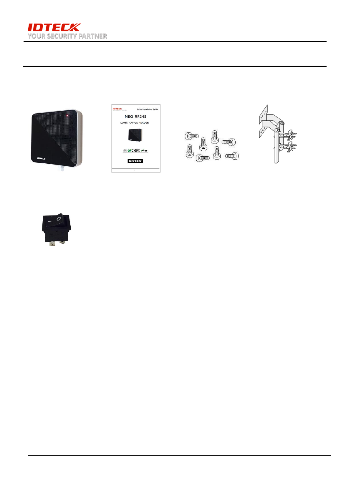
5. Identifying Supplied Parts
Unpack and check the contents. If any of these parts are missing, contact your distributor.
NEO RF245 Quick Installation Guide Mounting Bolts Mounting Bracket
ON/OFF Switch for
Reading range setting
6 December. 2016 Copyright IDTECK Co., Ltd.
Page 7

User Manual
6. Installation of the Product
7 December. 2016 Copyright IDTECK Co., Ltd.
Page 8

User Manual
Extra Purchase
Reader hood, bargate, loop coil and speed bump are extra purchase. (IDTECK doesn’t offer these
contents)
Reading Angle of NEO RF245
The reading angle of RF245 is approximately 90 degree at the front side of the reader. However the reader has
about 10% of the maximum reading distance at the rear side of the reader.
8 December. 2016 Copyright IDTECK Co., Ltd.
Page 9

User Manual
Applications
F.1 Parking Control (Island) F.2 Multiple Gates with OTR & HOLD Control
1. NEO RF245 is applicable in a various way as it shows in F.1 and F.2. However, because of the
characteristic of a long range reader, we recommend to have enough space between each of them when
installing multiple RF245 (ex: F.1 : 3m, F.2 : 5m at least).
2. In case of not being able to keep enough distance between two or more readers due to the spatial
constraints, a user can set desire reading range by adjusting the angle. If it is difficult to have enough
space between the NEO RF245 due to the spatial constraints,
3. Using a reader hood will diminish the reading range; therefore, set a speed bump at the crossing gate
ramp to extend the reading range, if desired. A speed limit has to be restricted to 20 Km/h or below.
9 December. 2016 Copyright IDTECK Co., Ltd.
Page 10

User Manual
Cable name
Color
Main Power(DC+12V)
Red
Power Ground(GND)
Black
Wiegand Data-0
Green
Wiegand Data-1
White
BARGATE1)
Gray
HOLD Loop INPUT2)
Blue
OTR INPUT3)
Yellow
RS232_TX
Purple
RS232_RX
Brown
BOOT_INPUT4)
Orange
7. Cable Color
1. BARGATE output (a transistor output) that directly controls a car circuit breaker is used for circuit
breaker control relay operation. The maximum current drain rate is 1 Amps.
2. HOLD input is used to force NEO RF245 to read a tag when loop sensor detects any approaching
vehicle. When a vehicle is detected, NC contact should be used, and the input should also be
disconnected from GND completely. In OTR mode, the reader will only output tag ID (1 time).
CAUTION: Nothing should be connected to this input unless loop sensor is in use.
3. OTR cable (yellow) is used to limit the reading time to 1 (OTR = One time reading).
4. When BOOT_INPUT is connected to GND during firmware upgrade, the system changes into
applicable mode.
CAUTION: Nothing should be connected to this input during normal operation.
10 December. 2016 Copyright IDTECK Co., Ltd.
Page 11

User Manual
Start(0x02h)
Card ID
(8 ASCII char.)
End(0x03h)
LRC(XOR)
total 11 bytes
8. Output Format and Timing
8-1. 26bit Wiegand output Timing
Data bit: 100us low active pulse
Interval between bits: 1ms
8-2. RS232 output format
Baud Rate: 9600bps, Parity: None, Data bit: 8, Stop bit: 1
LRC: Exclusive OR (XOR) from Start(0x02h) to End(0x03h)
8-3 Bargate output Timing
Low active pulse: 1 sec duration
Transistor (open collector) output
11 December. 2016 Copyright IDTECK Co., Ltd.
Page 12

User Manual
9. Wire Connection to Controller
NEO RF245 Wire Connection
# Notice
- Connect both yellow (OTR, one time reading) and white (WIEGAND-1) cable to the ON/OFF switch (the switch
must be ON when setting up reading range).
- Turn ON the switch when setting up reading range. Make sure to turn it OFF after a desired range is setup.
12 December. 2016 Copyright IDTECK Co., Ltd.
Page 13

User Manual
10. Operation
- Normal Operation Mode
10-1 Apply power to the reader. When power is supplied, the RF245 reader will automatically set its
frequency and site code, and go into standby mode. The red LED will be turned on after successful
initialization.
10-2 If a tag (IDA245N & IDA245) or IDA245N-H2 & IDA245H2) approaches the reader, the reader will
generate a beeping sound in every second. The green and red LED will blink on and off alternatively.
The reader will send 26bit Wiegand output, RS232, and BARGATE output to the controller at the same
time.
10-3 Bargate output:
When the reader detects a tag, it will generate 1s BARGATE control output through the Gray wire. The
BARGATE output is a transistor (open collector) output, with the maximum current drain of 1 A.
10-4 One time reading(OTR) control Input:
Connect OTR (yellow) cable to GND to activate One-Time-Reading mode. During this state, the reader
will only generate output signal when a tag is detected for the first time.
If a user needs to scan the same tag again, the particular tag must be completely out of the reading
range for at least 5 seconds, and scanned to the reader again. (The maximum number of cards that the
reader can detect at the same time during OTR more is 12. From the 13th tag, it will be detected as
“Continuous.”)
10-5 HOLD Control Input: (NC contacts required)
When the HOLD Control Input (Blue wire) is grounded, it will prevent the reader from reading the tag.
This can be used for vehicle detectors such as Loop Coil Sensor.
Hold Input with OTR function will only detect on tag ID. Please refer to the following figure.
13 December. 2016 Copyright IDTECK Co., Ltd.
Page 14

User Manual
- Reading range setting method
☞ NEO RF245 is suitable for any installation environment that the users can freely set the reading range
at the desired distance.
10-6 Power off NEO RF245.
10-7 Connect yellow (OTR, one time reading) and white (Wiegand_D1) cables together.
(You can use a enclosed switch to connect two cables together, as shown below. The switch must be
turned on before setting up reading range. Make sure to turn off when finished).
14 December. 2016 Copyright IDTECK Co., Ltd.
Page 15

User Manual
10-8 Power up NEO RF245.
10-9 Green and red LED will light up as shown below. The device will generate 10 beeping sounds for 10
seconds.
10-10 During those 10 seconds, scan a tag from a desired location. The tag should be scanned 10 straight
times. For the first 5 times of the scanning, a single sound (Bee) will be generated. From the 6th to 9th
times of scanning, double sound (Bee Beep) will be generated. At the last 10th time of scanning, triple
sound (Bee Bee Beep) will be generated. Now the distance of that 10th time of scanning will be
programmed as a new reading distance. When finished, the reading range setup will be finalized and
green LED will turn off.
15 December. 2016 Copyright IDTECK Co., Ltd.
Page 16

User Manual
10-11 Power off the device, and disconnect yellow and white cables (If used switch, simply turn OFF the
switch).
10-12 Power on the device. You can now scan the tag from the distance that has been programmed.
Scenario
- Current reading range is 2 meters, and you want to maximize the reading range. How?
1) Follow the steps above (5-6 and 5-7).
2) Wait until green LED turns off (DO NOT scan any tag until it fully goes off).
3) Follow the steps (5-9 to 5-10). Recognition distance shall be set with the maximum reading
range.
※ Note:
1. Reading range can have a margin of error that depends on installation circumstances.
2. The default reading range of NEO RF245 is set to maximum.
(Reading Range is definable according to each site's properties.)
16 December. 2016 Copyright IDTECK Co., Ltd.
Page 17

User Manual
11. FCC REGISTRATION INFORMATION
FCC Requirements Part 15
CAUTION: Any changes or modifications in construction of this device which are not expressly approved by the responsible
for compliance could void the user's authority to operate the equipment.
NOTE: This device complies with Part 15 of the FCC rules.
Operation is subject to the following two conditions;
1. This device may not cause harmful interface, and
2. This device must accept any interference received, including interference that may cause undesired operation.
This equipment has been tested and found to comply with the limits for a Class A Digital Device, pursuant to Part 15 of
the FCC rules. These limits are designed to this equipment generates, uses, and can radiate radio frequency energy and, if
not installed and used in accordance with the instructions, may cause harmful interference to radio communications.
However, there is no guarantee that interference will not occur in a particular installation. If this equipment does cause
harmful interference to radio or television reception, which can be determined by turning the radio or television off and on,
the user is encouraged to try to correct interference by one or more of the following measures.
1. Reorient or relocate the receiving antenna.
2. Increase the separation between the equipment and receiver.
3. Connect the equipment into an outlet on another circuit.
4. Consult the dealer or an experienced radio/TV technician for help.
17 December. 2016 Copyright IDTECK Co., Ltd.
Page 18

User Manual
12. Warranty policy and limitation of liability
IDTECK warrants this product against defects in material and workmanship for the period specified in the table below from
the date of purchase under normal customer use. This Warranty doesn’t apply: 1) to any product which has been
dismantled without authorization of IDTECK or/and has a damaged or detached QC label on its back side; 2) to any losses,
defects, or damages caused by improper testing, operation, installation, maintenance, modification, alteration, or
adjustment; 3) to any product with a damaged or faded serial number on it; or 4) to any losses, defects, or damages caused
by lightning or other electrical discharge, natural disaster, misuse, accident or neglect.
This Limited Warranty is in lieu of all other warranties, obligations, or liabilities on the part of IDTECK, and IDTECK
DISCLAIMS ANY AND ALL WARRANTY, WHETHER EXPRESS OR IMPLIED, OF MERCHANTABILITY OR FITNESS FOR A
PARTICULAR PURPOSE.IDTECK does not, and cannot, know who is present, what property is located, where this product will
be used; it would be extremely difficult to determine the actual damages that may result from a failure of the product to
perform as anticipated; and the low price of this product is based upon the nature of the product provided and the limited
liability that IDTECK assumes. IDTECK IS NOT RESPONSIBLE FOR ANY PERSONAL INJURY, PROPERTY DAMAGE OR LOSS,
DIRECT, SPECIAL, INCIDENTAL OR CONSEQUENTIAL DAMAGES, OR OTHER LOSS, AND IDTECK’S MAXIMUM LIABILITY SHALL
NOT IN ANY CASE EXCEED THE PURCHASE PRICE OF THE PRODUCT.
To obtain repair or replacement under the terms of this warranty, visit IDTECK’s Website (http://www.idteck.com) and place
an online RMA request. After an RMA code is issued, return the product along with the authorization RMA code.
18 December. 2016 Copyright IDTECK Co., Ltd.
Page 19

User Manual
13. How to Make RMA Request (After Sales Service)
To make the RMA request, the product must be initially registered on IDTECK webpage. After registering the
product, send it to IDTECK RMA Center. Please follow the instructions below:
1. Please register the RMA request via IDTECK webpage.
www.idteck.com [Customer Center] → [Technical Service] → [Online RMA] → [RMA Request]
※ Please refer to the IDTECK webpage for more details.
2. RMA Code will be issued after the RMA Center reviews the RMA request form.
3. Enclose the product along with the RMA Code and send it to IDTECK RMA Center. (Product without RM
A Code is not accepted.)
If you have any questions or problems regarding the RMA services, please contact us using the contact
information below. Friendly representatives at IDTECK are always standing by to provide the best after
sales services
IDTECK Headquarter
5F, Ace Techno Tower B/D, 468, Gangseo-ro,
Gangseo-Gu, Seoul, 07573, Korea
Tel: +82 2 2659 0055
Fax: +82 2 2659 0086
E-mail: webmaster@idteck.com
Website: www.idteck.com
IDTECK Production (RMA center)
5F, 404 (Nae-dong), Sinheung-ro, Wonmi-gu, Buchon-si, Kyonggi-do, 14489, Korea
Copyright@2014 IDTECK All Right Reserved.
Tel: 82-32-671-5642
Fax: 82-32-671-5641
E-mail: webmaster@idteck.com
Website: www.idteck.co.kr
IDTECK Global(America)
1555 Redondo Beach Blvd #100 Gardena, CA 90247
Tel: +1-310-819-8115
Fax: +1-702-421-2488
19 December. 2016 Copyright IDTECK Co., Ltd.
Page 20

User Manual
The specifications contained in this manual are subject to change without notice at any time.
5F, Ace Techno Tower B/D, 468, Gangseo-ro,
Gangseo-Gu, Seoul, 07573, Korea
Tel : +82-2-2659-0055
Fax : +82-2-2659-0086
E-mail : webmaster@idteck.com
Dec. 2016 Copyright IDTECK Co., Ltd.
 Loading...