

Page 1
Augusta and Augusta S
80145503-001
USER MANUAL
Rev. M
Revised: 19 August, 2019
Page 2

2019 ID Technologies, Inc. All rights reserved
ID TECH
10721 Walker Street, Cypress, CA90630 Voice: (714) 761-6368 Fax: (714) 761-8880
Visit us at http://www.idtechproducts.com
The information contained herein is provided to the user as a convenience. While every effort has been
made to ensure accuracy, ID TECH is not responsible for damages that might occur because of errors or
omissions, including any loss of profit or other commercial damage, nor for any infringements or patents
or other rights of third parties that may result from its use. The specifications described herein were
current at the time of publication but are subject to change at any time without prior notice.
LIMITED WARRANTY
ID TECH warrants to the original purchaser for a period of 12 months from the date of invoice that this
product is in good working order and free from defects in material and workmanship under normal use
and service. ID TECH’s obligation under this warranty is limited to, at its option, replacing, repairing, or
giving credit for any product that returned to the factory of origin with the warranty period and with
transportation charges and insurance prepaid, and which is, after examination, disclosed to ID TECH’s
satisfaction to be defective. The expense of removal and reinstallation of any item or items of
equipment is not included in this warranty. No person, firm, or corporation is authorized to assume for
ID TECH any other liabilities in connection with the sales of any product. In no event shall ID TECH be
liable for any special, incidental or consequential damages to purchaser or any third party caused by any
defective item of equipment, whether that defect is warranted against or not. Purchaser’s sole and
exclusive remedy for defective equipment, which does not conform to the requirements of sales, is to
have such equipment replaced or repaired by ID TECH. For limited warranty service during the warranty
period, please contact ID TECH to obtain a Return Material Authorization (RMA) number & instructions
for returning the product.
THIS WARRANTY IS IN LIEU OF ALL OTHER WARRANTIES OF MERCHANTABILITY OR FITNESS FOR
PARTICULAR PURPOSE. THERE ARE NO OTHER WARRANTIES OR GUARANTEES, EXPRESS OR IMPLIED,
OTHER THAN THOSE HEREIN STATED. THIS PRODUCT IS SOLD AS IS. IN NO EVENT SHALL ID TECH BE
LIABLE FOR CLAIMS BASED UPON BREACH OF EXPRESS OR IMPLIED WARRANTY OF NEGLIGENCE OF ANY
OTHER DAMAGES WHETHER DIRECT, IMMEDIATE, FORESEEABLE, CONSEQUENTIAL OR SPECIAL OR FOR
ANY EXPENSE INCURRED BY REASON OF THE USE OR MISUSE, SALE OR FABRICATIONS OF PRODUCTS
WHICH DO NOT CONFORM TO THE TERMS AND CONDITIONS OF THE CONTRACT.
ID TECH and Value through Innovation are trademarks of International Technologies & Systems
Corporation. USB (Universal Serial Bus) specification is copyright by Compaq Computer Corporation,
Intel Corporation, Microsoft Corporation, and NEC Corporation. Windows is registered trademarks of
Microsoft Corporation. Quick Chip is a Visa specification. M/Chip Fast is a Master Card specification.
Augusta KB with Quick Chip and M/Chip Fast is patent-pending.
Copyright 2019 ID TECH. All rights reserved. Document Number: 80145503-001
Page 2 of 32
Page 3

Revision History
Revision
Date
Description of Changes
By
50
12/20/2015
Initial draft
KT
50a
12/30/2015
Misc. corrections as suggested by Engineering
KT
51
01/12/2016
Misc. updates regarding data formats and serial
KT
52
03/10/2016
Incorporated LM's command tables.
USB descriptors added.
KT
53
03/24/2016
Table format applied to remaining commands.
commands.
KT
B
04/08/2016
Add Set Encryption and Get Encryption Control
(78 53 01 07 and 78 52 01 07).
KT
C
06/22/2016
Added LCD Foreign Language Mapping Table (for
LCD messaging).
KT
D
10/25/2016
Added Terminal Configurations appendix.
KT
K
04/18/2019
Font and format update
supported
CB
L
07/08/2019
Added SRED Decommissioning text
CB M 08/19/2019
Added power consumption specifications
CB
commands (now called USB communication
commands).
Remove references to LCD commands and
outputs.
Added Appendix on Function IDs.
New language added to clarify the difference
between ITP and NGA commands.
Table added, to clarify the categories of NGA
EMV-required LCD messages).
Added info for 49 72 01 responses (EMV-required
13.0: Removed tag DFEF59; it is no longer
Copyright 2019 ID TECH. All rights reserved. Document Number: 80145503-001
Page 3 of 32
Page 4

Table of Contents
1. INTRODUCTION 5
1.1. QUICK CHIP AND M/CHIP FAST SUPPORT 6
1.2. SRED SUPPORT 6
2. SOFTWARE INTEGRATION 7
3. FEATURES 8
4. APPLICABLE DOCUMENTS 9
5. SPECIFICATIONS 9
5.1. STRUCTURE 9
5.2. DURABILITY/RELIABILITY 9
5.3. ENVIRONMENTAL 10
5.4. POWER MANAGEMENT 10
5.5. PHYSICAL DIMENSIONS 11
5.6. AGENCY APPROVALS AND COMPLIANCES 12
6. DECOMMISSIONING SRED DEVICES 12
7. BASE FUNCTIONALITY 12
7.1. SMART CARD FUNCTION 12
7.2. MAGNETIC STRIPE FUNCTION 12
7.3. INTERFACE FUNCTION 12
7.4. KEY INJECTION FUNCTION 13
7.5. REMOTE KEY INJECTION FUNCTION 13
7.6. BOOTLOADER FUNCTION 13
8. USB COMMUNICATION 14
8.1. ITP PROTOCOL FORMAT 14
8.2. NGA PROTOCOL FORMAT 15
8.3. USB DESCRIPTORS 16
USB-HID 16
USB-KB 18
8.4. USB KB COMMUNICATION COMMAND AND RESPONSE FORMAT 21
Data Formats 22
MSR Modes of Operation 22
Auto Mode 22
Buffer Mode 23
9. EMV L2 DATA OUTPUT FORMATS 24
9.1. STANDARD TRANSACTION MODE 24
9.2. NO DATA ENCRYPTION KEY & NO TRANSARMOR CERTIFICATE: 24
9.3. TDES/AES MODE & DATA ENCRYPTION KEY EXIST: 24
9.4. TRANSARMOR MODE & TRANSARMOR CERTIFICATE EXISTS: 25
9.5. QUICK CHIP AND M/CHIP FAST TRANSACTION MODE 26
9.6. NO DATA ENCRYPTION KEY & NO TRANSARMOR CERTIFICATE: 27
9.7. TDES/AESMODE & DATA ENCRYPTION KEY EXIST: 27
9.8. TRANSARMORMODE &TRANSARMOR CERTIFICATE EXIST: 28
10. BASIC OPERATION 29
11. TROUBLESHOOTING 29
12. APPENDIX A: QUICK CHIP AND M/CHIP FAST SUPPORT 30
13. HOW TO ENABLE QUICK CHIP AND M/CHIP FAST MODE 30
14. FASTER EMV (QUICK CHIP) DATA 31
Copyright 2019 ID TECH. All rights reserved. Document Number: 80145503-001
Page 4 of 32
Page 5

1. Introduction
ID TECH’s Augusta series reader is a hybrid MagStripe and EMV ICC card reader, built for
maximum durability, security, and cost-effectiveness. It is available in both non-SRED
(Augusta) and PCI SRED (Augusta S) versions. The standard Augusta supports TDES or AES
data encryption (with TransArmor encryption as an option), with DUKPT key management,
and remote key injection as an option. An SRED version of the reader, Augusta S, is available
for customers who require the tamper protection, fulltime encryption, command
authentication, and other features of SRED.
The Augusta product line is specifically designed for a hybrid MagStripe/ICC card
environment, and provides user-friendly interface features (such as blue-colored “Point of
Interaction” LED indicators) that make it easy and fast for users to determine where/when
to swipe or insert cards. A traditional “green/blue/red” LED status indicator is also provided
for clear indication of overall event status. In addition, an audible beeper can indicate
alert/error status, and remind the user to remove his or her card at the end of an EMV
transaction. Combined, the LEDs and audible beeper features provide user-friendly cues that
enable a fast, efficient transaction.
The Augusta product provides a logical migration path for existing ID TECH MiniMag and
SecureMag customers who wish to migrate from a magstripe-only POS platform to a
platform that provides EMV ICC functionality. Augusta does this by providing a “dual mode”
communication structure that allows it to operate in either “Legacy Mode” or “EMV Hybrid
Mode.”
In Legacy Mode, the Augusta acts as a conventional “magstripe only” device that is
command-compatible with the existing ID TECH SecureMag product line (when
communicating over USB-KB). This allows the Augusta to be a drop-in, plug-and-play
replacement within existing SecureMag environments. Likewise, the Augusta maintains the
same physical mounting features as the MiniMagII product. Thus, existing
MiniMag/SecureMag customers can purchase the Augusta as a direct replacement product,
with confidence that the Augusta’s ICC features will “future proof” their investment for
migration to an EMV chip-card environment.
In EMV Hybrid Mode, the Augusta transforms into a fully featured EMV L1/L2 ICC and
MagStripe card reader using a USB-HID interface. In this mode, the Augusta is no longer
command-compatible with the SecureMag product line. This document describes the
command set and protocol used in Augusta's EMV Hybrid Mode.
Copyright 2019 ID TECH. All rights reserved. Document Number: 80145503-001
Page 5 of 32
Page 6

1.1. Quick Chip and M/Chip Fast Support
Augusta-series readers with firmware at V1.01.003 or higher support firmware-integrated
Quick Chip and M/Chip Fast, allowing for 2-sec EMV transactions in USB Keyboard mode
(compatible with virtual terminals) – a patent-pending ID TECH innovation. (Note: The ID
TECH patent applies to the keyboard-mode implementation, not Quick Chip itself.) See
Appendix A for more information.
1.2. SRED Support
Augusta S incorporates PCI-PTS 4.x SRED (Secure Read and Exchange of Data) support, for
the most demanding security environments. Note that Augusta S is dimensionally the same
as standard Augusta but has a Part Number that contains '851.' Augusta S supports Quick
Chip and M/Chip Fast (as described above and in Appendix A) as well as all normal modes of
the standard Augusta, but incorporates additional security features:
• Augusta S incorporates advanced tamper-detection features, including circuitry that
will automatically zero out encryption keys (rendering the unit useless to an
attacker) if the unit is opened or disassembled.
• Augusta S features fulltime encryption: No sensitive data will ever be output in
plaintext format.
• Encryption in SRED mode is TDES.
• Sensitive commands require MAC authentication. In particular, the following
commands require authentication in Augusta S:
o Set White List
o Set Date & Time
o Set CA Public Key
o Set Certification Revocation List
o New KSN/Key Pair
• Optionally, transaction output may contain a MAC hash of sensitive track data. See further
discussion at EMV L2 Data Output as well as the Set Verify Encrypt Data Output command.
Copyright 2019 ID TECH. All rights reserved. Document Number: 80145503-001
Page 6 of 32
Page 7

2. Software Integration
When it comes to creating software that communicates with the Augusta, the developer has
several choices:
• Two-way USB-KB communication via Legacy Mode protocol and command set
• One-way (read only) USB-KB communication in Quick Chip and M/Chip Fast mode
• Direct USB-HID communication via EMV Hybrid Mode protocol and command set
• ID TECH Universal SDK (Supports Windows, iOS, and Android environments)
ID TECH suggests that Windows developers use the C#-based Universal SDK whenever
possible. This powerful development platform reduces integration complexity and cuts
development time significantly by providing a library of routines that allow convenience
access to commonly used functions. Also, the SDK is supported by sample code and
test/debug utilities that make it easier for ID TECH to support the developer.
The Universal SDK and related documentation can be downloaded from the ID TECH
website. Please contact ID TECH customer support (support@idtechproducts.com) for
further information, or check for the latest downloads at
https://atlassian.idtechproducts.com/confluence/display/KB/Downloads+-+Home
Downloads do not require registration.
.
Copyright 2019 ID TECH. All rights reserved. Document Number: 80145503-001
Page 7 of 32
Page 8

3. Features
ID TECH's Augusta is a state-of-the-art EMV ICC contact reader with the ability to fall back to
conventional magstripe interactions. Its features include the following:
• Encryption-capable 3-track magstripe swipe-reader and EMV ICC "insert" reader
• Supports encrypted or non-encrypted operation
• PCI certified SRED version available
• EMV Level 1 and Level 2 certified
• Built-in support for Quick Chip and M/Chip Fast in keyboard mode (patent pending)
• Compact size, mounting compatible with MiniMagII product
• User-friendly LED indicators for card insertion location/point of interaction
• Tri-color LED to indicate reader status, good/bad card reads, etc.
• Audio feedback to signal good/bad card reads and alert status
• Support for Triple DES or AES encryption methods
• Support for TransArmor encryption
• Support for DUKPT key management
• Supports ID TECH standard TR31 (and optional TR34) based Remote Key Injection
• Rated for 1,000,000 magstripe card swipes and 500,000 ICC card insertions
• On-board battery-backed RTC (Real Time Clock) for transaction timestamping
• RoHS and REACH compliant
• 1-year manufacturer's warranty
• Firmware can be upgraded in the field via the communication interfaces
• SDKs available for C# on Windows and Java on Android
• Tamper detection and tamper-triggered key zeroization (Augusta S only)
• Compatible with virtual terminal environments (keyboard output)
Copyright 2019 ID TECH. All rights reserved. Document Number: 80145503-001
Page 8 of 32
Page 9

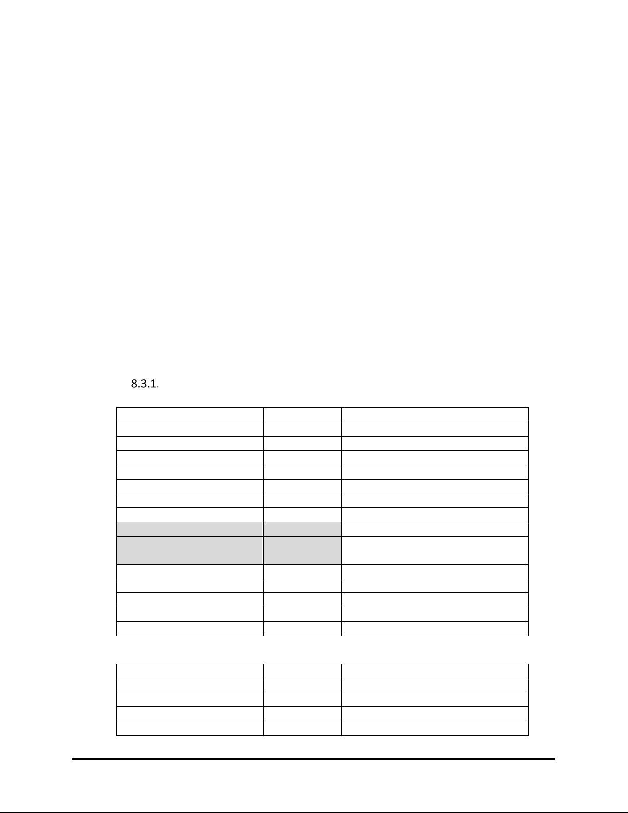
4. Applicable Documents
No.
Item
Specification
1
Magnetic Head
1,000,000 swipes minimum
2
Rail
1,000,000 swipes minimum
3
Smartcard connector
500,000 inserts minimum
4
Drop Test
Unit is able to withstand 4 ft. drop to concrete on 6 surfaces and
4 corners (6 cycles) and remain functionally intact
5
IK Test
IK08
6
IP Test
IP50 when placed horizontal; IP52 when unit is mounted
vertical.
7
Electrostatic discharge
Electronics can survive ESD of 8kV contact, and 12kV air
discharge, with no loss of communications
8
MTBF
120,000 POH minimum
1
Physical Dimensions
Maximum 127mm x 52mm x 35mm
L x W x H
2
Structure Material
Plastic
3
Status LED
Tri-color LED to indicate reader status
Blue, Red, Green
4
ICC LED
Blue LEDs to indicate ICC card insertion
5
Magnetic Head
3 tracks read head
6 Head material
Permalloy
7 Slot width
1.0mm (MSR) or 0.9mm (ICC)
8 Card format
ISO-7816
9 ICC Contact force
0.2 to 0.6N
10
Battery
3.0V lithium
5 yr life
11
Beeper
75db @4KHz
ISO 7810 Identification cards -- Physical characteristics
ISO 7811 Identification Cards -- Tracks 1 through 3
ISO 7816 Identification cards -- Integrated circuit cards
ISO 4909 Magnetic stripe content for Track 3
EMV Contact Specifications for Payment Systems Version 4.3
5. Specifications
5.1. Structure
No. Item Specification Note
5.2. Durability/Reliability
Copyright 2019 ID TECH. All rights reserved. Document Number: 80145503-001
Page 9 of 32
Page 10

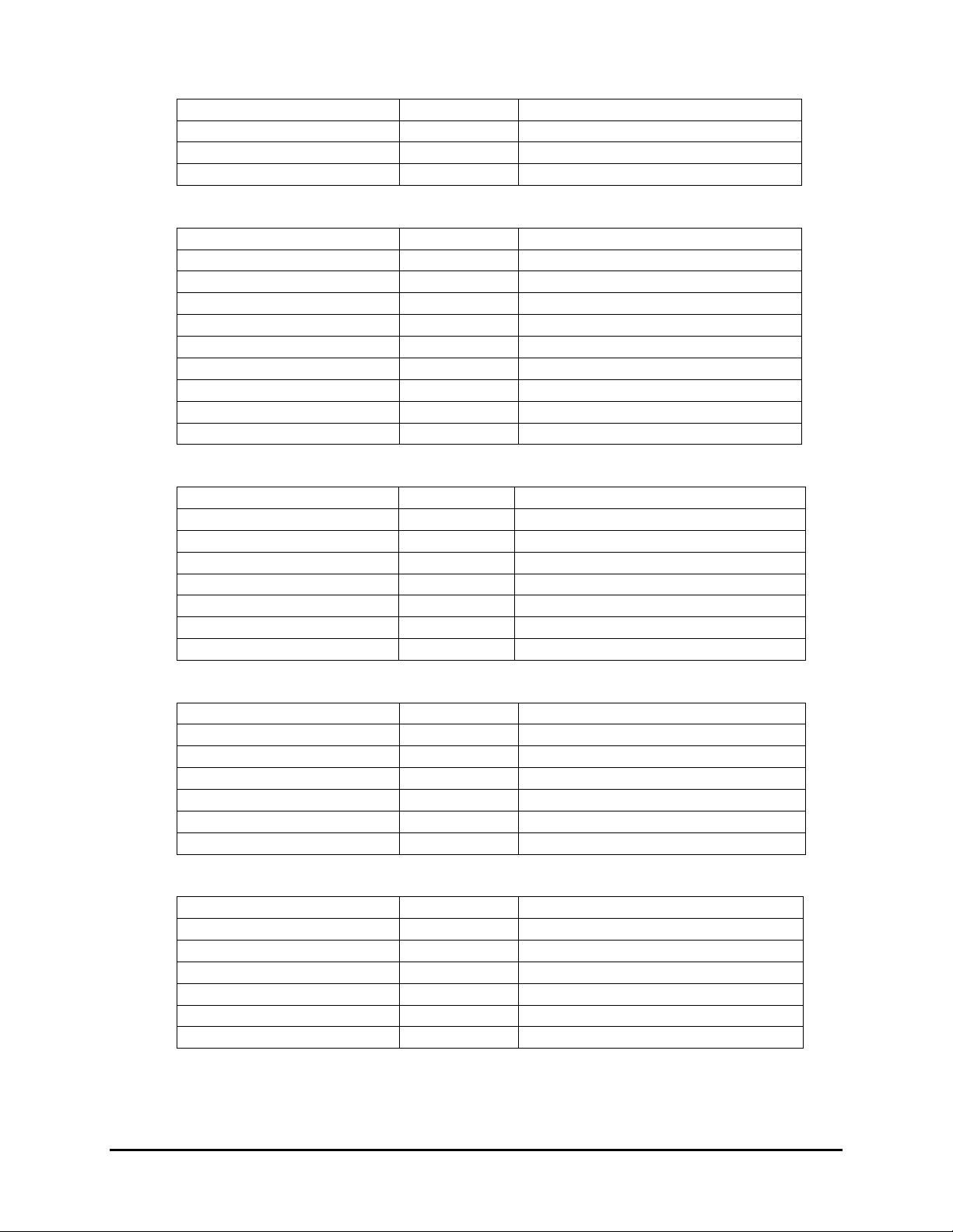
5.3. Environmental
Tested Parameter
Current measured
Power on (Normal)
68 mA
Suspend Circuit
1.5 mA
ICC Power On
88 mA (max)
ICC LED ON (Replace LED 5mA)
122 mA
ICC LED ON (Original LED 2mA)
91.6 mA
Item
Specification
Note
Operating
Temperature
0 to 55°C (32 to 131°F)
Non-condensing.
Storage Temperature
-25 to 65°C (-13 to 149°F)
Non-condensing.
Relative humidity
Maximum 95%
Non-condensing
ESD
Contact
±8kV
Air discharge
±12KV
5.4. Power Consumption
Power Management
USB interface cable provides power from VBUS at 5VDC.
Copyright 2019 ID TECH. All rights reserved. Document Number: 80145503-001
Page 10 of 32
Page 11

5.5. Physical Dimensions
Copyright 2019 ID TECH. All rights reserved. Document Number: 80145503-001
Page 11 of 32
Page 12

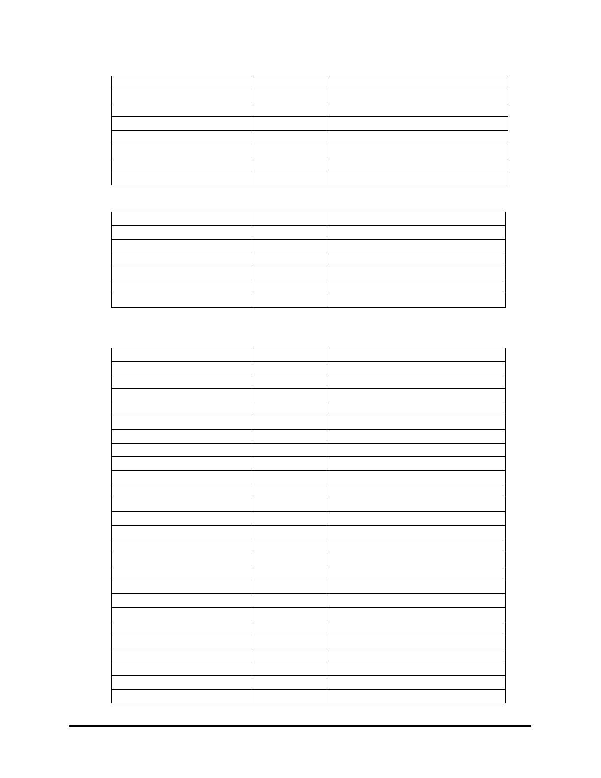
5.6. Agency Approvals and Compliances
Item
Regulation & Class
Note
CE
EN55022/EN55024, Class- B
FCC
Part 15, Class-B
RoHS
DIRECTIVE 2011/65/EU
Pb,Hg,Cr6+,PBDE,PBB < 1000ppm
Cd < 100ppm
REACH Compliance with REACH regulation
EMV Contact L1&L2
PCI SRED 4.1 Augusta S version only
IK rating IK08
IP rating IP52
6. Decommissioning SRED Devices
All PCI devices require proper decommissioning prior to device disposal in order to ensure the
protection of all sensitive financial card data. For instructions on decommissioning your device,
see Decommissioning of SRED Devices on the ID TECH Knowledge Base.
7. Base Functionality
7.1. Smart Card function
• EMV Level 1 approval.
• Reads ISO 7816 (1,2,3,4) (T=0, T=1) (Class A, B) microprocessor cards.
• Monitor Card Seated Status.
• TDES and AES Encryption.
• DUKPT key management.
7.2. Magnetic Stripe function
• Meets ISO 7811 (Supports AAMVA format and JIS II Card format).
• Support single, dual or triple tracks.
• Bi-directional reading.
• TDES or AES Encryption.
• DUKPT key management.
• PCI PTS 4.x Function Supported SRED.
7.3. Interface function
The device can communicate with the host via USB-KB or USB-HID.
Copyright 2019 ID TECH. All rights reserved. Document Number: 80145503-001
Page 12 of 32
Page 13

7.4. Key injection function
Compatible with FutureX HSM for Data Key Injection.
Can communicate with Mobile devices (Related Protocol) via USB-HID port.
(Note: ID TECH is a certified Key Injection Facility. Talk to your ID TECH representative about getting
units key-injected.)
7.5. Remote Key Injection function
Compatible with Local POS Computer (LPC) for Data Key Injection.
Can communicate with Local POS Computer (LPC) via USB port.
Contact your ID TECH representative for information about obtaining Remote Key Injection services.
7.6. Bootloader function
The firmware can be upgraded via USB.
Copyright 2019 ID TECH. All rights reserved. Document Number: 80145503-001
Page 13 of 32
Page 14

8. USB Communication
Two-way communication can occur with Augusta using USB-KB (for SecureMag compatibility mode; that
is, magstripe-only operation) or via USB-HID (magstripe plus EMV). When a unit is placed in Quick Chip
and M/Chip Fast mode, it operates read-only, in keyboard mode.
In MSR-only Legacy mode (two-way USB-KB, non-Quick-Chip), commands are sent and received using
the ID Tech ITP Protocol (a simple command/response scheme that wraps data with start and end codes
plus an LRC, or longitudinal redundancy check, value; see below). In combined EMV+MSR mode (that is,
USB-HID mode; EMV enabled), commands are sent via ID Tech NGA Protocol (a simple command-andresponse scheme; see details further below).
For the complete firmware-command API, see document 80145504-001, ID TECH Augusta Low-Level
Command API Guide (available at
https://atlassian.idtechproducts.com/confluence/display/KB/Downloads+-+Home
8.1. ITP Protocol Format
• <STX> is defined as 0x02
• <ETX> is defined as 0x03
• <ACK> is defined as 0x06
• <NAK> is defined as 0x15
.)
Configuration Setting Command: <STX><S><FuncSETBLOCK1>…<FuncBLOCKn><ETX><LRC>
Response: <ACK> or <NAK> for wrong command (invalid funcID, length and value)
Configuration Review Command: <STX><R><ReviewID><ETX><LRC>
Response: <ACK> <STX> <FuncID> <Len> <FuncData> <ETX> <LRC 2>
<FuncID>, <Len> and <FuncData> definition are same as described above.
Note: ReviewID (value 0x1F) will return all funcID-s.
Where:
• <Length> = is a two-byte counter (high then low) from <Command ID> to the byte before
LRC
• <Command ID> = is a one byte value identifying a specific command ID.
• <FuncID> = is a one byte Function ID, which identifies the particular function or settings
affected.
• <Len> = is a one-byte length count for the data block “<FuncData>”
• <FuncData> = is the data block for the function
<Response Data> = is the data block associated with the Response.
<Status> is a two byte value indicating the success or failure of a command. There are a few
responses without status. e.g. Version command.
Copyright 2019 ID TECH. All rights reserved. Document Number: 80145503-001
Page 14 of 32
Page 15

Note that the LRC comes at the end and represents the XOR of all preceding byte values including STX
and ETX.
8.2. NGA Protocol Format
<STX><CLenL><CLenH><Command_Body/Response_Body/Notification/Output
Body/Input Body>…<LRC> <CheckSum><ETX>
• Function Command
Command Format:
<TaskID><F><Command>…
Response:
If valid command and no problem during execution
<ACK>[<Response>]…
Otherwise
<NAK><ErrorCode1>][<ErrorCode2>
• Setting Command
Command Format:
<TaskID> <S> <00> or
<TaskID><S><NoFunc><FuncBlock>
Where:
• <TaskID> <S> <00> means Default the Task
• <All (0x7F)> <S> <00> means Default All
• <NoFunc> is number of function blocks to set in a task. Now only support <NoFunc> = 1
• <FuncBlock> has the following format of <FuncID><Len><FuncData>
• <FuncID> is a one byte Property ID.
• <Len> is a one byte length count for a setting <FuncData>.
• <FuncData> is a setting for a property.
Response:
If valid command and no problem during execution
<ACK>
Or (fail)
<NAK><ErrorCode1><ErrorCode2>
For setting command, reader will scan command first and send back error codes if it found any
error(s), and do setting if no error has been found.
<Unknown ID in Setting/Review list> (1600) and <Setting value out of
range> (1400) will be treated as warning. i.e.: Do setting for other properties but skip setting for
those properties which have warning. Warning will be sent to host.
• Host Review Command
Command Format:
<TaskID><R><00> or
Copyright 2019 ID TECH. All rights reserved. Document Number: 80145503-001
Page 15 of 32
Page 16
<TaskID><R><NoFunc><FuncID>
Field
Value (Hex)
Description (ACR38)
Length
12
Length = 18
Des type
01 BCD USB
00 02
USB 2.0
Device Class
00
Not specific
Sub Class
00
Unused
Device Protocol
00
Unused
Max Packet Size
40
Max Packet Size is 64 bytes
VID
0A CD
PID
38 20 (39 20
for SRED)
BCD Device Release
00 01
i-Manufacture
01 i-Product
02 i-Serial-Number
03 # Configuration
01
Field
Value (Hex)
Description
Length
09 Des type
02 Total Length
29 00
No. Interface
01
Where:
<NoFunc> is number of properties to review in a task. Now only support <NoFunc> = 1
<TaskID><R><00> allows host to review all properties in a task.
<TaskID><R><01><FuncID> allows host to review setting for a property.
Response:
<ACK><TaskID><NoFunc><FuncBLOCK> or (fail)
<NAK><ErrorCode1><ErrorCode2>
<TaskID> is needed for each <FuncID> in review command.
Note that in contrast to the ITP format, in NGA protocol the LRC value does not come at the end, and
does not include STX, length bytes, nor ETX in its calculated XOR value.
8.3. USB Descriptors
Following are the USB descriptors used by Augusta. The detailed information should be adjusted and
tested as need be during implementation.
USB-HID
Device Descriptor:
Configuration Descriptor:
Copyright 2019 ID TECH. All rights reserved. Document Number: 80145503-001
Page 16 of 32
Page 17
Configuration Value
01 iConfiguration
00 Attributes
A0
Bus power; With remote wakeup
Power
32
100 mA
Field
Value (Hex)
Description
Length
09 Des type
04 Interface No.
00 Alternator Setting
00 # EP
02 Interface Class
03
HID
Sub Class
00 Interface Protocol
00 iInterface
00
Field
Value (Hex)
Description
Length
09 bDescriptorType
21
HID
bcdHID(L/H)
11 01
Rev 1.11
bCountryCode
00 bNumDescriptors
01 bDescriptorType
22
Report
wDescriptorLength(L/H)
1C 00
L H
Field
Value
Description
Length
07 Des Type
05
End Point
EP Addr
02
EP2 Out, Command Down
Attributes
03
Interrupt
wMaxPacketSize
40 00
64 Bytes
bInterval
04
4 milliseconds
Field
Value
Description
Length
07 Des Type
05
End Point
EP Addr
81
EP1 In, Response Up
Attributes
03
Interrupt
Size
40 00
64 Bytes
Interval
04
4 milliseconds
Interface Descriptor: (USB-HID)
HID Descriptor:
End Point Descriptor: (EP2)
End Point Descriptor: (EP1)
Copyright 2019 ID TECH. All rights reserved. Document Number: 80145503-001
Page 17 of 32
Page 18

USB-KB
Field
Value (Hex)
Description (ACR38)
Length
12
Length = 18
Des type
01 bcd USB
00 02
USB 2.0
Device Class
00
Not specific
Sub Class
00
Unused
Device Protocol
00
Unused
Max Packet Size
08
Max Packet Size is 8 bytes
VID
0A CD
PID
38 10 (39 10
for SRED)
BCD Device Release
00 01
i-Manufacture
01 i-Product
02 i-Serial-Number
03 # Configuration
01
Field
Value (Hex)
Description
Length
09 Des type
02 Total Length
22 00
No. Interface
01 Configuration Value
01 iConfiguration
00 Attributes
80
Bus power; Without remote wakeup
Power
32
100 mA
Field
Value (Hex)
Description
Length
09 Des type
04 Interface No.
00 Alternator Setting
00 # EP
01 Interface Class
03
HID
Sub Class
01
01:boot
Interface Protocol
02
02:keyboard
iInterface
00
USB-KB communication may be used when the Augusta is in SecureMag-compatibility mode (magstripe
only). For EMV/ICC-enabled operation, use USB-HID instead.
Device Descriptor:
Configuration Descriptor:
Interface Descriptor: (USB-HID)
Copyright 2019 ID TECH. All rights reserved. Document Number: 80145503-001
Page 18 of 32
Page 19
HID Descriptor:
Field
Value (Hex)
Description
Length
09 bDescriptorType
21
HID
bcdHID(L/H)
11 01
Rev 1.11
bCountryCode
00 bNumDescriptors
01 bDescriptorType
22
Report
wDescriptorLength(L/H)
52 00
L H
Field
Value
Description
Length
07 Des Type
05
End Point
EP Addr
81
EP1 In
Attributes
03
Interrupt
Size
08 00
8 Bytes
Interval
01
1 milliseconds
Field
Value (Hex)
Description
Usage Page
05 01
Generic Desktop
Usage
09 06
Keyboard
Collection
A1 01
Application
Usage Page
05 07
Key codes
Usage Minimum
19 E0
224
Usage Maximum
29 E7
231
Logical Minimum
15 00
0
Logical Maximum
25 01
1
Report Size
75 01
1
Report Count
95 08
8
Input
81 02
Data, Variable, Absolute
Report Count
95 01
1
Report Size
75 08
Input
85 01
Constant
Report Count
95 05
5
Report Size
75 01
Usage Page
05 08
LED
Usage Minimum
19 01
1
Usage Maximum
29 05
5
Output
91 02
Data Var Absolute
Report Count
95 01
1
Report Size
75 03
Output
91 01
Constant
Report Count
95 06
6
End Point Descriptor: (EP1)
HID report descriptor for IDTech Key Board Protocol
Copyright 2019 ID TECH. All rights reserved. Document Number: 80145503-001
Page 19 of 32
Page 20

Report Size
75 08
Logical Minimum
15 00
0
Logical Maximum
25 66
102
Usage Page
05 07
Key codes
Usage Minimum
19 00
Usage Maximum
29 66
102
Input
81 00
Data,Array
Usage Page
06 2D FF
ID TECH
Report Count
95 01
1
Logical maximum
26 FF 00
255
Logical Minimum
15 01
Report Size
75 08
Usage
09 20
Setup data byte
Report Count
95 08
Feature
B2 02 01
Data Var, Abs
End Collection
C0
Copyright 2019 ID TECH. All rights reserved. Document Number: 80145503-001
Page 20 of 32
Page 21

8.4. USB KB Communication Command and Response Format
The Augusta supports USB-KB communication (only) while in “Legacy Mode.”
Legacy Mode is compatible with ID TECH’s “SecureMag” magstripe-only card reader.
Please see ID TECH manual P/N 80096504-001, the SecureMag Encrypted MagStripe Reader User
Manual, for additional information regarding the SecureMag (Legacy Mode) protocol and command set.
Note that USB-KB commands use ID Tech's ITP protocol, in which commands are wrapped with STX
(0x02) and ETX (0x03), followed by an LRC value that represents the XOR of all preceding byte values.
(No checksum is used.) For example:
Command: 52 22 (Get Firmware Version)
This command would be sent as (hex) 02 52 22 03 71, where 0x71 is the LRC value.
USB HID Communication Command and Response Format
In EMV Hybrid Mode, Augusta uses ID TECH proprietary NGA protocol format commands and responses
in USB communications. The NGA protocol exchanges data using the following format:
<0x02> <Len_Low><Len_High> <Command Body/Response
Body/Notification Body> <LRC> <CheckSUM> <0x03>
Where:
• <0x02> is STX (Start of Text)
• <Len_Low><Len_High> is the length of the <Command Body/Response
Body/Notification Body> in hexadecimal byte values.
• <LRC> is LRC (exclusive OR) of <Command Body/Response Body/Notification
Body> byte values. (XOR all bytes together. The result is the LRC.)
• <CheckSUM> is SUM of <Command Body/Response Body/Notification Body>
values, disregarding overflow. (Add all bytes; the result, mod-256, is the checksum.)
• <0x03> is ETX (End of Text)
• Response Body is [<Response Status> + <Response Data>]
<Response Status>: 1 byte.
<Response Data>: n bytes.
If <Response Status> is ACK, Several bytes needed.
If <Response Status> is NAK, Response data is Error code (2 bytes), or Error code
(2 bytes) + Tag (1 or 2 bytes; this is for ICC L2 response).
• Command Body is [<Command> + <Command Parameters>]
• Notification Body is [ xxxxxxxxxxxxxxxxxxxx ]
Copyright 2019 ID TECH. All rights reserved. Document Number: 80145503-001
Page 21 of 32
Page 22

Note that NGA commands tend to begin with a high nibble value 7:
Command Prefix
Category
72
ICC (smart card commands)
73
MSR (magstripe commands)
75
PCI Miscellaneous
78
Configuration commands
7F
Reserved
In a multi-byte NGA command, the first byte indicates the category (as shown above); the second byte is
typically one of 'F', 'R', or 'S' (Function, Read, Set; hex 0x46, 0x52, or 0x53 respectively); and the third
byte is the specific function ID.
Data Formats
Note that when a chip-card (ICC) transaction is performed, EMV data will be returned using a tag-based
(TLV) representation as described in detail in ID TECH P/N 80000502-001 ID Tech Encrypted Data Output.
When a conventional magstripe (MSR) transaction is performed, MSR data will be returned following
the ID TECH Enhanced Encrypted MSR Data Format described in ID TECH P/N 80000502-001 ID Tech
Encrypted Data Output.
MSR Modes of Operation
MSR operation occurs in two modes: Auto or Buffer.
Auto Mode
Auto mode means MSR data will be auto sent out once magnetic card was swiped.
It is supported only in USB-KB interface; it is the default behavior. Auto Mode can be disabled.
After MSR data were auto-sent out, the Buffer Data will be erased directly.
Copyright 2019 ID TECH. All rights reserved. Document Number: 80145503-001
Page 22 of 32
Page 23

USB-KB with ITP Protocol
USB-HID with NGA Protocol
Step 0
If device is Auto Mode or Disable Buffer
Mode, Set to Enable Buffer Mode.
If device is Disable Buffer Mode, Set to
Enable Buffer Mode.
Step 1
Send “Arm to Read” Command.
If receive ACK, enter next step.
Send “Arm to Read” Command.
If receive ACK, enter next step.
Step 2
While in this state, User can swipe Card.
While in this state, User can swipe Card.
Buffer Mode
Buffer mode means MSR data will be sent out in response to the Read Buffer Data command.
It is supported in USB-HID interface or USB-KB interface. Buffer Mode can be disabled.
Implementation:
Timeout is 30 seconds.
Send “Read Buffer Data” to read MSR data.
The response should be:
• NAK for No Swipe Card and No Timeout,
and Buffer is erased. or
• NAK for No Swipe Card and Timeout. or
• ACK + “Successful MSR Data” for swipe
OK, and Buffer is erased. or
• NAK for swipe failed, and Buffer is
erased.
If send “Read Buffer Data” before send “Arm
to Read” , the response should be 0x18.
After Swipe Card, the MSR data should be
exist at most 15 Minutes. If timeout, Buffer
is erased.
Timeout is 30 seconds.
Send “Read Buffer Data” to read MSR data.
The response should be:
• NAK + “No Swipe Card Error” for No
Swipe Card and No Timeout, and Buffer
is erased. or
• NAK + “Timeout Error” for No Swipe
Card and Timeout. or
• “Successful MSR Data” for swipe OK,
and Buffer is erased. or
• NAK + “Failed Get MSR Data” for swipe
failed, and Buffer is erased.
If send “Read Buffer Data” before send “Arm
to Read” , the response should be NAK +
“Operate Error”
After Swipe Card, the MSR data should be
exist at most 15 Minutes. If timeout, Buffer
is erased.
Copyright 2019 ID TECH. All rights reserved. Document Number: 80145503-001
Page 23 of 32
Page 24

9. EMV L2 Data Output Formats
9.1. Standard Transaction Mode
The following sections describe data outputs that apply in USB-HID mode (as opposed to Keyboard
mode involving Quick Chip; see Quick Chip and M/Chip Fast Transaction Mode
details). For addition detail on data output formats for MSR and EMV, see ID TECH document 80000502001, ID TECH Encrypted Data Output Formats.pdf, available from
https://atlassian.idtechproducts.com/confluence/display/KB/Downloads+-+Home.
9.2. No Data encryption Key & No TransArmor Certificate:
ErrorResponse Body: 15 04 00
The Response Data – 02 <Len_L><Len_H>15 04 00<LRC><SUM> 03
9.3. TDES/AES mode & Data encryption Key exist:
Without MAC Data Output:
EMV L2 Transaction Result – 06 <2 bytes Response Code><Attribution><DF EF 12 0A
(10 bytes KSN)><5A A1 08 (8 bytes Tag5A Mask Data)><5A C1 10 (16 bytes
Tag5A Encryption Data)><57 A1 13 (19 bytes Tag57 Mask Data)><57 C1
18/20 (24 bytes/32bytes Tag57 Encryption Data)><9F 1F C1 N (N bytes
Tag9F1F Encryption Data)><9F 20 n (n bytes Raw Value)><TLV1><TLV2> …
<TLVn><DF EF 4C 06 00 26 00 10 00 00><DF EF 4D 38/40 (56/64 bytes
Encrypted Trk1_Data Trk2_Data Trk3_Data PAN_Data)>
The Response Data – 02 <Len_L><Len_H> 06 <2 bytes Response
Code><Attribution><DF EF 12 0A (10 bytes KSN)><5A A1 08 (8 bytes Tag5A
Mask Data)><5A C1 10 (16 bytes Tag5A Encryption Data)><57 A1 13 (19
bytes Tag57 Mask Data)><57 C1 18/20 (24 bytes/32bytes Tag57 Encryption
Data)><9F 1F C1 N (N bytes Tag9F1F Encryption Data)><9F 20 n (n bytes
Raw Value)><TLV1><TLV2> … <TLVn><DF EF 4C 06 00 26 00 10 00 00><DF EF
4D 38/40 (56/64 bytes Encrypted Trk1_Data Trk2_Data Trk3_Data
PAN_Data)><LRC><SUM> 03
With MAC Data Output:
EMV L2 Transaction Result – 06 <2 bytes Response Code><Attribution><DF EF 12 0A
(10 bytes KSN)><5A A1 08 (8 bytes Tag5A Mask Data)><5A C1 10 (16 bytes
Tag5A Encryption Data)><57 A1 13 (19 bytes Tag57 Mask Data)><57 C1
18/20 (24 bytes/32bytes Tag57 Encryption Data)><9F 1F C1 N (N bytes
Tag9F1F Encryption Data)><9F 20 n (n bytes Raw Value)><TLV1><TLV2> …
<TLVn><DF EF 4C 06 00 26 00 10 00 00><DF EF 4D 38/40 (56/64 bytes
Encrypted Trk1_Data Trk2_Data Trk3_Data PAN_Data)><DF EF 41 10 (16
bytes MAC Value)><DFEF420A (10 bytes MAC Key KSN)>
The Response Data – 02 <Len_L><Len_H> 06 <2 bytes Response
Code><Attribution><DF EF 12 0A (10 bytes KSN)><5A A1 08 (8 bytes Tag5A
Copyright 2019 ID TECH. All rights reserved. Document Number: 80145503-001
Page 24 of 32
further below for more
Page 25

Mask Data)><5A C1 10 (16 bytes Tag5A Encryption Data)><57 A1 13 (19
bytes Tag57 Mask Data)><57 C1 18/20 (24 bytes/32bytes Tag57 Encryption
Data)><9F 1F C1 N (N bytes Tag9F1F Encryption Data)><9F 20 n (n bytes
Raw Value)><TLV1><TLV2> … <TLVn><DF EF 4C 06 00 26 00 10 00 00><DF EF
4D 38/40 (56/64 bytes Encrypted Trk1_Data Trk2_Data Trk3_Data
PAN_Data)><DF EF 41 10 (16 bytes MAC Value)><DF EF 42 0A (10 bytes MAC
Key KSN)><LRC><SUM> 03
9.4. TransArmor Mode & TransArmor Certificate Exists:
Without MAC Data Output:
Step1:
EMV L2 Transaction Result – 06 <2 bytes Response Code><Attribution><DF EF 12 0A
(10 bytes KSN)><DF EE 26 02 (2 bytes data)><5A A1 08 (8 bytes Tag5A
Mask Data)><5A C201 58 (344 bytes Tag5A TransArmor Data)><57 A1 13 (19
bytes Tag57 Mask Data)><57 C201 58 (344 bytes Tag57 TransArmor
Data)><TLV1><TLV2> … <TLVn><DF EF 48 0A DF EF 4C DF EF 4D 9F 1F 9F 20>
The Response Data – 02 <Len_L><Len_H> 06 <2 bytes Response
Code><Attribution><DF EF 12 0A (10 bytes KSN)><DF EE 26 02 (2 bytes
data)><5A A1 08 (8 bytes Tag5A Mask Data)><5A C201 58 (344 bytes Tag5A
TransArmor Data)><57 A1 13 (19 bytes Tag57 Mask Data)><57 C201 58 (344
bytes Tag57 TransArmor Data)><TLV1><TLV2> … <TLVn><DF EF 48 0A DF EF
4C DF EF 4D 9F 1F 9F 20><LRC><SUM> 03
Step2:
Terminal can send “Retrieve Transaction Result” command with 4 tags (DFEF4C, DFEF4D, 9F1F and 9F20)
to get them.
The response Data - 06 <DF EF 4C 06 00 26 00 10 00 00><DF EF 4D 82 02 B0 (344
bytes Tag57 TransArmor Data) (344 bytes Tag5A TransArmor Data)><9F 1F
C2 01 58 (344 bytes Tag9F1F TransArmor Data) ><DF EF 48 02 9F 20>
The Response Data – 02 <Len_L><Len_H> 06 <DF EF 4C 06 00 26 00 10 00 00><DF
EF 4D 82 02 B0 (344 bytes Tag57 TransArmor Data) (344 bytes Tag5A
TransArmor Data)><9F 1F C2 01 58 (344 bytes Tag9F1F TransArmor Data)
><DF EF 48 02 9F 20><LRC><SUM> 03
Step3:
Terminal can send “Retrieve Transaction Result” command with 4 tags (9F20) to get them
The response Data - 06 <9F 20 C2 01 58 (344 bytes Tag9F20 TransArmor Data) >
The Response Data – 02 <Len_L><Len_H> 06 <9F 20 C2 01 58 (344 bytes Tag9F20
TransArmor Data) ><LRC><SUM> 03
Copyright 2019 ID TECH. All rights reserved. Document Number: 80145503-001
Page 25 of 32
Page 26

With MAC Data Output:
Step1:
EMV L2 Transaction Result – 06 <2 bytes Response Code><Attribution><DF EF 12 0A
(10 bytes KSN)><DF EE 26 02 (2 bytes data)><5A A1 08 (8 bytes Tag5A
Mask Data)><5A C201 58 (344 bytes Tag5A TransArmor Data)><57 A1 13 (19
bytes Tag57 Mask Data)><57 C201 58 (344 bytes Tag57 TransArmor
Data)><TLV1><TLV2> … <TLVn><DF EF 48 0A DF EF 4C DF EF 4D 9F 1F 9F
20><DF EF 41 10 (16 bytes MAC Value)><DF EF 42 0A (10 bytes MAC Key
KSN)>
The Response Data – 02 <Len_L><Len_H> 06 <2 bytes Response
Code><Attribution><DF EF 12 0A (10 bytes KSN)><DF EE 26 02 (2 bytes
data)><5A A1 08 (8 bytes Tag5A Mask Data)><5A C201 58 (344 bytes Tag5A
TransArmor Data)><57 A1 13 (19 bytes Tag57 Mask Data)><57 C201 58 (344
bytes Tag57 TransArmor Data)><TLV1><TLV2> … <TLVn><DF EF 48 0A DF EF
4C DF EF 4D 9F 1F 9F 20><DF EF 41 10 (16 bytes MAC Value)><DF EF 42 0A
(10 bytes MAC Key KSN)><LRC><SUM> 03
Step2:
Terminal can send “Retrieve Transaction Result” command with 4 tags (DFEF4C, DFEF4D, 9F1F and 9F20)
to get them
The response Data - 06 <DF EF 4C 06 00 26 00 10 00 00><DF EF 4D 82 02 B0 (344
bytes Tag57 TransArmor Data) (344 bytes Tag5A TransArmor Data)><9F 1F
C2 01 58 (344 bytes Tag9F1F TransArmor Data) ><DF EF 48 02 9F 20><DF
EF 41 10 (16 bytes MAC Value)><DF EF 42 0A (10 bytes MAC Key KSN)>
The Response Data – 02 <Len_L><Len_H> 06 <DF EF 4C 06 00 26 00 10 00 00><DF
EF 4D 82 02 B0 (344 bytes Tag57 TransArmor Data) (344 bytes Tag5A
TransArmor Data)><9F 1F C201 58 (344 bytes Tag9F1F TransArmor Data)
><DF EF 48 02 9F 20><DF EF 41 10 (16 bytes MAC Value)><DF EF 42 0A (10
bytes MAC Key KSN)><LRC><SUM> 03
Step3:
Terminal can send “Retrieve Transaction Result” command with 4 tags (9F20) to get them
The response Data - 06 <9F 20 C2 01 58 (344 bytes Tag9F20 TransArmor Data)
><DF EF 41 10 (16 bytes MAC Value)><DF EF 42 0A (10 bytes MAC Key
KSN)>
The Response Data – 02 <Len_L><Len_H> 06 <9F 20 C2 01 58 (344 bytes Tag9F20
TransArmor Data) ><DF EF 41 10 (16 bytes MAC Value)><DF EF 42 0A (10
bytes MAC Key KSN)><LRC><SUM> 03
9.5. Quick Chip and M/Chip Fast Transaction Mode
This mode of operation is used in conjunction with USB "Keyboard" mode (KB), a mode in which the card
reader acts as a keyboard device, outputting data spontaneously upon card presentation.
Copyright 2019 ID TECH. All rights reserved. Document Number: 80145503-001
Page 26 of 32
Page 27

9.6. No Data encryption Key & No TransArmor Certificate:
Error Response Body: 15 04 00
The Response Data – 02 <Len_L><Len_H>15 04 00<LRC><SUM> 03
9.7. TDES/AESmode & Data encryption Key exist:
Transaction OK:
EMV L2 Transaction Result – 06 <2 bytes Response Code><Attribution><DF EF 12 0A
(10 bytes KSN)><DF EF 5B 08 (8 bytes Tag5A Mask Data)><5A 10 (16 bytes
Tag5A Encryption Data)><DF EF 5D 13 (19 bytes Tag57 Mask Data)><57
18/20 (24 bytes/32bytes Tag57 Encryption Data)><9F 1F N (N bytes
Tag9F1F Encryption Data)><9F 20 N (N bytes Raw Value)><TLV1><TLV2> …
<TLVn><DF EF 4C 06 00 26 00 10 00 00><DF EF 4D 38/40 (56/64 bytes
Encrypted Trk1_Data Trk2_Data Trk3_Data PAN_Data)>
Without MAC Data Output:
KB final output (Ascii Code) – <DF EE 25 02 (2 bytes Response Code)><DF EE 26 02
(2 bytes Attribution)><DF EF 12 0A (10 bytes KSN)><DF EF 5B 08 (8
bytes Tag5A Mask Data)><5A 10 (16 bytes Tag5A Encryption Data)><DF EF
5D 13 (19 bytes Tag57 Mask Data)><57 18/20 (24 bytes/32bytes Tag57
Encryption Data)><9F 1F N (N bytes Tag9F1F Encryption Data)><9F 20 N
(N bytes Raw Value)><TLV1><TLV2> … <TLVn><DF EF 4C 06 00 26 00 10 00
00><DF EF 4D 38/40 (56/64 bytes Encrypted Trk1_Data Trk2_Data
Trk3_Data PAN_Data)>
With MAC Data Output:
KB final output (Ascii Code) – <DF EE 25 02 (2 bytes Response Code)><DF EE 26 02
(2 bytes Attribution)><DF EF 12 0A (10 bytes KSN)><DF EF 5B 08 (8
bytes Tag5A Mask Data)><5A 10 (16 bytes Tag5A Encryption Data)><DF EF
5D 13 (19 bytes Tag57 Mask Data)><57 18/20 (24 bytes/32bytes Tag57
Encryption Data)><9F 1F N (N bytes Tag9F1F Encryption Data)><9F 20 N
(N bytes Raw Value)><TLV1><TLV2> … <TLVn><DF EF 4C 06 00 26 00 10 00
00><DF EF 4D 38/40 (56/64 bytes Encrypted Trk1_Data Trk2_Data
Trk3_Data PAN_Data)><DF EF 41 10 (16 bytes MAC Value)><DF EF 42 0A (10
bytes MAC Key KSN)>
Note: msgX is <DF EE 25 02 (2 bytes Response Code)> … …<DF EF 4C 06 00 26
00 10 00 00><DF EF 4D 38/40 (56/64 bytes Encrypted Trk1_Data Trk2_Data
Trk3_Data PAN_Data)><DF EF 41 10>
Transaction Error:
EMV L2 Transaction Result – 15 + <2 bytes Error Code>
KB final output (Ascii Code) – <DF EF 61 02 (2 bytes Error Code)>
Copyright 2019 ID TECH. All rights reserved. Document Number: 80145503-001
Page 27 of 32
Page 28

9.8. TransArmormode &TransArmor Certificate exist:
Step1:
Transaction OK:
EMV L2 Transaction Result – 06 <2 bytes Response Code><Attribution><DF EF 12 0B
(11 bytes KID)><DF EE 26 02 (2 bytes data)><DF EF 5B 08 (8 bytes Tag5A
Mask Data)><5A 8201 58 (344 bytes Tag5A TransArmor Data)><DF EF 5D 13
(19 bytes Tag57 Mask Data)><57 8201 58 (344 bytes Tag57 TransArmor
Data)><TLV1><TLV2> … <TLVn><DF EF 48 0A DF EF 4C DF EF 4D 9F 1F 9F 20>
Without MAC Data Output:
KB final output (Ascii Code) – <DF EE 25 02 (2 bytes Response Code)><DF EE 26 02
(2 bytes Attribution)><DF EF 12 0B (11 bytes KID)><DF EE 26 02 (2
bytes data)><DF EF 5B 08 (8 bytes Tag5A Mask Data)><5A 8201 58 (344
bytes Tag5A TransArmor Data)><DF EF 5D 13 (19 bytes Tag57 Mask
Data)><57 8201 58 (344 bytes Tag57 TransArmor Data)><TLV1><TLV2> …
<TLVn><DF EF 48 0A DF EF 4C DF EF 4D 9F 1F 9F 20>
With MAC Data Output:
KB final output (Ascii Code) – <DF EE 25 02 (2 bytes Response Code)><DF EE 26 02
(2 bytes Attribution)><DF EF 12 0B (11 bytes KID)><DF EE 26 02 (2
bytes data)><DF EF 5B 08 (8 bytes Tag5A Mask Data)><5A 8201 58 (344
bytes Tag5A TransArmor Data)><DF EF 5D 13 (19 bytes Tag57 Mask
Data)><57 8201 58 (344 bytes Tag57 TransArmor Data)><TLV1><TLV2> …
<TLVn><DF EF 48 0A DF EF 4C DF EF 4D 9F 1F 9F 20><DF EF 41 10 (16
bytes MAC Value)><DF EF 42 0A (10 bytes MAC Key KSN)>
Note: msgX is <DF EE 25 02 (2 bytes Response Code)> … … <DF EF 41 10>
Transaction Error:
EMV L2 Transaction Result – 15 + <2 bytes Error Code>
KB final output (Ascii Code) - <DF EF 61 02 (2 bytes Error Code)>
Step2:
Without MAC Data Output:
KB final output (Ascii Code) – <DF EF 4C 06 00 26 00 10 00 00><DF EF 4D 82 02 B0
(344 bytes Tag57 TransArmor Data) (344 bytes Tag5A TransArmor
Data)><9F 1F 82 01 58 (344 bytes Tag9F1F TransArmor Data) ><DF EF 48
02 9F 20>
With MAC Data Output:
KB final output (Ascii Code) – <DF EF 4C 06 00 26 00 10 00 00><DF EF 4D 82 02 B0
(344 bytes Tag57 TransArmor Data) (344 bytes Tag5A TransArmor
Data)><9F 1F 82 01 58 (344 bytes Tag9F1F TransArmor Data) ><DF EF 48
02 9F 20><DF EF 41 10 (16 bytes MAC Value)><DF EF 42 0A (10 bytes MAC
Key KSN)>
Note: msgX is <DF EF 4C 06 00 26 00 10 00 00> … … <DF EF 41 10>
Copyright 2019 ID TECH. All rights reserved. Document Number: 80145503-001
Page 28 of 32
Page 29

Step3:
Without MAC Data Output:
KB final output (Ascii Code) – <9F 20 82 01 58 (344 bytes Tag9F20
TransArmor Data) >
With MAC Data Output:
KB final output (Ascii Code) – <9F 20 82 01 58 (344 bytes Tag9F20 TransArmor
Data) ><DF EF 41 10 (16 bytes MAC Value)><DF EF 42 0A (10 bytes MAC
Key KSN)>
Note: msgX is <9F 20 82 01 58 (344 bytes Tag9F20 TransArmor Data) ><DF
EF 41 10>
10. Basic Operation
The Augusta derives its power from the 5VDC associated with the USB connection. (No extra power
cords are needed.) Simply plug the Augusta into any PC, laptop, or other host that supports standard
USB-A connectivity.
Note: No special drivers are needed in order to use Augusta. If your Windows machine pauses to
download a driver automatically, the first time you plug in your Augusta, simply accept all defaults, and
continue.
To perform a magstripe read, slide a card (stripe facing the body of the Augusta) through the side slot of
the Augusta, in either direction.
To perform a chip-card transaction, dip a chip card into the ICC slot and remove it when the unit beeps
or your POS software indicates that you should remove your card.
11. Troubleshooting
The Augusta is extremely simple and reliable, and should require no special troubleshooting. If the
power-on light fails to illuminate when the unit is plugged in, try plugging the Augusta into a knowngood USB receptacle (possibly on a different machine). Likewise, if communication with Augusta is ever
lost, simply unplug the unit and plug it back in; communication should be restored.
Augusta has no user-serviceable parts and should not be disassembled in any way. Augusta S, in
particular, incorporates anti-tamper features that will activate if any attempt is made to disassemble the
unit. (Any cryptographic keys in the unit will be erased, and the unit will need to be sent back to the
manufacturer to be made serviceable again.)
If you should need to open a customer support case, visit
https://atlassian.idtechproducts.com/jira/servicedesk/customer/portal/3/user/login?destination=portal
%2F3 or send an e-mail to support@idtechproducts.com (which will automatically open a Tech Support
case).
Copyright 2019 ID TECH. All rights reserved. Document Number: 80145503-001
Page 29 of 32
Page 30

12. Appendix A: Quick Chip and M/Chip Fast Support
ID TECH Augusta-series readers are designed to support the Quick Chip and M/Chip Fast EMV modality
when operating in USB-KB mode. This is sometimes referred to as Faster EMV.
Quick Chip and M/Chip Fast is a particular way of doing contact-EMV transactions, designed to shorten
the amount of time the cardholder spends waiting to remove his or her card from the reader. For
most chip cards, the overall "card inserted" time is on the order of 2.0 seconds. (For cards that lack
Payment System Environment capability on the chip, the overall time can be as long as 7.0 seconds,
because communication with the gateway or acquirer may be required before the card can be
removed from the reader. In Quick Chip, this communication can occur after the card is already
removed from the reader.)
Quick Chip and M/Chip Fast is an online-only style of interaction, hence it is especially appropriate for
markets that are traditionally online-only, such as the U.S. retail market. It relies on terminal
configuration changes (not kernel changes), and a hard-coded chain of events surrounding Gen AC
requests, to achieve its functional goals. For detailed information about how Quick Chip and M/Chip
Fast works, be sure to consult the U.S. Payments Forum white paper at:
http://www.emv-connection.com/downloads/2016/09/Optimizing-Txn-Speed-WP-FINAL-February-
2017.pdf
ID TECH's Augusta-series readers offer Faster EMV, or Quick Chip and M/Chip Fast capability, in
conjunction with USB-Keyboard (USB-KB) mode, which is a patent-pending combination that allows
Augusta to provide EMV-readiness in a virtual terminal environment. Combining EMV with Keyboard
Mode means it becomes exceptionally easy for virtual terminals to support contact EMV transactions
in a browser environment.
When a customer presents a card for a Quick Chip and M/Chip Fast transaction, Augusta reads the
card (and carries out all the usual steps of an EMV transaction, except for Issuer Authentication and
the processing of Issuer Scripts; these steps are not done in Quick Chip and M/Chip Fast), and then it
outputs TLV data as keystrokes (which is to say, ASCII-renderable hex values) straight to the host
computer. The "keystrokes" will show up in whatever text window (or text field, in a web form)
currently has focus. (The payment application can intercept these keystrokes as needed, to
parse/filter them, insert appropriate values in appropriate form fields, and/or go online for
authorization.)
The following section describes the configuration steps needed to put an Augusta reader into Quick
Chip and M/Chip Fast Mode. Please note that once the reader is in this mode, all EMV transactions will
occur in USB-KB mode using Quick Chip and M/Chip Fast. (MSR transactions will occur in USB-KB mode
as well.) It is possible to switch the reader back to USB-HID mode at any time.
The procedures and screenshots below assume that the user is able to utilize ID TECH's Windowsbased Universal Demo software (available for free download at
https://atlassian.idtechproducts.com/confluence/display/KB/Downloads+-+Home
).
13. How To Enable Quick Chip and M/Chip Fast Mode
To enable Quick Chip and M/Chip Fast, first ensure that the reader's firmware is at V1.01.003 or
higher. Then perform the following steps.
Copyright 2019 ID TECH. All rights reserved. Document Number: 80145503-001
Page 30 of 32
Page 31

Tag
Meaning
DFEF5A
Terminal Data Setting - Tags to Return
DFEF5B
Mask for Tag5A
DFEF5C
Mask for Tag56
1. Enable the 5C configuration of Terminal Capabilities by issuing the 72 53 01 28 01 35
command. (For more about terminal configurations, see Appendix H.)
2. Use the Save Terminal Configuration command in the Universal Demo to set the values of
minor-config terminal TLVs as desired, making sure 5C is enabled. (See arrows in the screen
shot below.)
3. Set the CA Public Key
if it has never been set, and load any AIDs or do any other initializations
you wish to do, before proceeding.
4. Set the device to Quick Chip and M/Chip Fast Mode by issuing the following command: 72
53 01 29 01 31.
5. Finally, change the device's USB mode to USB-KB by issuing the following command: 78 53
01 10 02 02 00.
14. Faster EMV (Quick Chip) Data
The output from a Quick Chip and M/Chip Fast transaction consists predominantly of standard EMV
tag data, since Quick Chip and M/Chip Fast is, in fact, just EMV. However, you might also encounter
certain ID TECH proprietary tags (as follows):
Copyright 2019 ID TECH. All rights reserved. Document Number: 80145503-001
Page 31 of 32
Page 32

DFEF5D
Mask for Tag57
DFEF5E
Mask for Tag9F6B
DFEF5F
Mask for TagFFEE13 (track 1)
DFEF60
Mask for TagFFEE14 (track 2)
DFEF61
Error Code
DFEF62
Allow MSR Swipe data from ICC Card
Send tags DFEF5A and/or DFEF62 as Terminal Configuration values to control (respectively) the
Default Amount of the transaction (normally zero, for Quick Chip), the "tags to return" as part of each
transaction, and whether or not to enforce a policy of preferring EMV over MSR if a card has a chip.
For tag DFEF62, if the value = 0x01, then any MSR swipe with an ICC card requires the card to be
inserted instead of returning MSR swipe data. (In other words: MSR swipe data from an ICC card can
only be captured in a fallback situation.) If the value = 0x00, any card swiped (MSR or ICC) is allowed to
return MSR swipe data.
Other tags returned in a Quick Chip transaction will conform to EMVCo standard usage. Some tags
may be encrypted: for details, see ID TECH document P/N 80000502-001, Encrypted Data Output.
An example of USB-KB data output from a Quick Chip and M/Chip Fast transaction (using Visa ADVT
Test Card No. 43) is:
DF EE 25 02 00 02 DF EE 26 02 20 00 DF EE 12 0A 62 99 49 00 75 00 02 A0 02
90 DF EF 5D 11 47 61 CC CC CC CC 04 32 D1 01 22 01 CC CC CC CC CC 57 18 D0 18
2C 6B 2D F9 C4 D2 CD 60 B7 74 C7 65 AF 14 0E 7B 53 F7 78 39 62 9A DF EF
5B 08 47 61 CC CC CC CC 04 32 5A 08 D0 18 2C 6B 2D F9 C4 D2 5F 20 1A 56 49 53
41 20 41 43 51 55 49 52 45 52 20 54 45 53 54 20 43 41 52 44 20 34 33 5F
24 03 10 12 31 5F 25 03 95 07 01 5F 28 02 08 40 5F 2A 02 08 40 5F 2D 00 5F
34 00 5F 57 01 00 50 0B 56 49 53 41 20 43 52 45 44 49 54 4F 00 82 02 5C
00 84 07 A0 00 00 00 03 10 10 8C 15 9F 02 06 9F 03 06 9F 1A 02 95 05 5F 2A 02
9A 03 9C 01 9F 37 04 8D 17 8A 02 9F 02 06 9F 03 06 9F 1A 02 95 05 5F 2A 02 9A
03 9C 01 9F 37 04 8E 0E 00 00 00 00 00 00 00 00 1E 03 02 03 1F 00 9C 01 00 9F
02 06 00 00 00 00 00 00 9F 03 06 00 00 00 00 00 00 9F 10 07 06 01 0A 03 21 99
00 9F 13 00 9F 20 00 9F 26 08 34 BB F5 DC 19 F3 95 24 9F 27 01 00 9F 34 03 1E
03 00 9F 36 02 01 04 9F 37 04 9F A2 99 23 9F 38 00 9F 39 01 07 9F 4D 00 9F
4F 00 95 05 42 C0 00 00 00 9B 02 E8 00 8A 02 5A 33 99 00 9F 5B 00
Tags and lengths are shown in boldface. The KSN occurs in tag DFEE12. Sensitive fields (such as tag 5A)
are encrypted and/or masked.
Copyright 2019 ID TECH. All rights reserved. Document Number: 80145503-001
Page 32 of 32
 Loading...