

Page 1

2DScan
TM
Barcode Scanner
User’s Manual
80108502-001 rev.A
Page 2

FCC WARNING STATEMENT
This equipment has been tested and found to comply with the limits for a Class B
digital device, pursuant to Part 15 of FCC Rules. These limits are designed to
provide reasonable protection against harmful interference when the equipment is
operated in a commercial environment. This equipment generates, uses, and can
radiate radio frequency energy and, if not installed and used in accordance with the
instruction manual, may cause harmful interference to radio communications.
FCC COMPLIANCE STATEMENT
This device complies with Part 15 of the FCC Rules. Operation of this device is
subject to the following conditions: this device may not cause harmful interference
and this device must accept any interference received, including interference that
may cause undesired operation.
CANADIAN DOC STATEMENT
This digital apparatus does not exceed the Class B limits for radio noise for digital
apparatus set out in the Radio Interference Regulations of the Canadian Department
of Communications.
Le présent appareil numérique n’émet pas de bruits radioélectriques dépassant les
limites applicables aux appareils numériques de las classe B prescrites dans le
Réglement sur le brouillage radioélectrique édicté par les ministère des
Communications du Canada.
CE STANDARDS
Testing for compliance to CE requirements was performed by an independent
laboratory. The unit under test was found compliant to class B limits of part 15 of the
FCC rules.
Page 3

LIMITED WARRANTY
ID TECH warrants to the original purchaser for a period of 36 months from the date
of invoice that this product is in good working order and free from defects in material
and workmanship under normal use and service. ID TECH’s obligation under this
warranty is limited to, at its option, replacing, repairing, or giving credit for any
product which has, within the warranty period, been returned to the factory of origin,
transportation charges and insurance prepaid, and which is, after examination,
disclosed to ID TECH’s satisfaction to be thus defective. The expense of removal
and reinstallation of any item or items of equipment is not included in this warranty.
No person, firm, or corporation is authorized to assume for ID TECH any other
liabilities in connection with the sales of any product. In no event shall ID TECH be
liable for any special, incidental or consequential damages to purchaser or any third
party caused by any defective item of equipment, whether that defect is warranted
against or not. Purchaser’s sole and exclusive remedy for defective equipment,
which does not conform to the requirements of sales, is to have such equipment
replaced or repaired by ID TECH. For limited warranty service during the warranty
period, please contact ID TECH to obtain a Return Material Authorization (RMA)
number & instructions for returning the product.
THIS WARRANTY IS IN LIEU OF ALL OTHER WARRANTIES OF MERCHANT
ABILITY OR FITNESS FOR PARTICULAR PURPOSE. THERE ARE NO OTHER
WARRANTIES OR GUARANTEES, EXPRESS OR IMPLIED, OTHER THAN
THOSE HEREIN STATED. THIS PRODUCT IS SOLD AS IS. IN NO EVENT SHALL
ID TECH BE LIABLE FOR CLAIMS BASED UPON BREACH OF EXPRESS OR
IMPLIED WARRANTY OF NEGLIGENCE OF ANY OTHER DAMAGES WHETHER
DIRECT, IMMEDIATE, FORESEEABLE, CONSEQUENTIAL OR SPECIAL OR FOR
ANY EXPENSE INCURRED BY REASON OF THE USE OR MISUSE, SALE OR
FABRICATIONS OF PRODUCTS WHICH DO NOT CON-FORM TO THE TERMS
AND CONDITIONS OF THE CONTRACT
The information contained herein is provided to the user as a convenience. While
every effort has been made to ensure accuracy, ID TECH is not responsible for
dam-ages that might occur because of errors or omissions, including any loss of
profit or other commercial damage, nor for any infringements or patents or other
rights of third parties that may result from its use. The specifications described
herein were current at the time of publication, but are subject to change at any time
without prior notice.
© 2009 International Technologies & Systems Corporation. The information
contained herein is provided to the user as a convenience. While every effort has
been made to ensure accuracy, ID TECH is not responsible for damages that might
occur because of errors or omissions, including any loss of profit or other
commercial damage. The specifications described herein were current at the time of
publication, but are subject to change at any time without prior notice.
ID TECH is a registered trademark of International Technologies & Systems
Corporation. 2DScan and Value through Innovation are trademarks of International
Technologies & Systems Corporation.
Page 4

Page I
请更换节标题
Table of Contents
Content
About this guide
Introduction ................................................................................................................................................. 1
Chapter Description ..................................................................................................................................... 1
Graphic Notations ........................................................................................................................................1
Getting to Start
Introduction .................................................................................................................................................. 2
Getting to know 2DScan............................................................................................................................... 3
Unpacking ............................................................................................................................................. 3
Outline ..................................................................................................................................................3
Data Interface ........................................................................................................................................4
Communication Ports ..................................................................................................................................5
Connecting with USB Cable ........................................................................................................................ 6
Connecting with RS232 Cable ..................................................................................................................... 7
Connecting with PS/2 Cable ........................................................................................................................8
Removal of Communication Cable ..............................................................................................................9
ON, OFF, IDLE, RESTART ......................................................................................................................10
Maintenance ............................................................................................................................................... 10
Reading .......................................................................................................................................................11
Depth of Field ............................................................................................................................................ 13
Specifications ............................................................................................................................................. 14
Programming the Engine
Introduction ................................................................................................................................................ 15
Code Programming ............................................................................................................................. 15
Command Programming ..................................................................................................................... 15
QuickSet Programming ......................................................................................................................15
Programming Notation ..............................................................................................................................16
Code Programming On/Off........................................................................................................................17
Illumination ................................................................................................................................................ 18
Aiming ....................................................................................................................................................... 19
Beep ........................................................................................................................................................... 20
Decoding Beep ....................................................................................................................................20
Decoding Beep Type ........................................................................................................................... 20
Decoding Beep Volume ...................................................................................................................... 21
Power On Beep ...................................................................................................................................21
Beep Denotation (Beeper Definitions) ...............................................................................................21
Reading Mode ............................................................................................................................................ 22
Reading Timeout and Delay ...................................................................................................................... 23
Sensitivity ..................................................................................................................................................24
Exposure Imaging Mode ............................................................................................................................ 25
Default .......................................................................................................................................................26
Factory Default ................................................................................................................................... 26
User Default ........................................................................................................................................ 26
Query Product Information ........................................................................................................................ 27
Page 5

Page II
Table of Contents
RS232 Interface
Introduction ................................................................................................................................................ 28
Serial Port ..................................................................................................................................................29
Baud Rate ............................................................................................................................................29
Parity Check ........................................................................................................................................30
Hardware Auto Flow Control(only for 2DScan) ........................................................................30
Data Bits Transmitted .........................................................................................................................31
Stop Bits ..............................................................................................................................................31
USB Interface
Introduction ................................................................................................................................................ 32
USB HID-KBW ......................................................................................................................................... 33
USB Country Keyboard Types ...........................................................................................................34
USB Country Keyboard Types ...........................................................................................................35
Unknown Characters, Beep ................................................................................................................ 36
Emulate ALT + keypad ....................................................................................................................... 37
Function Key Mapping .......................................................................................................................38
ASCII Function Key Mapping Table .................................................................................................. 39
Keystroke Delay .................................................................................................................................40
Caps Lock ........................................................................................................................................... 40
Convert Case ....................................................................................................................................... 41
Emulate Numeric Keypad ...................................................................................................................42
USB DataPipe ............................................................................................................................................43
USB COM Port Emulation ........................................................................................................................ 44
HID-POS .................................................................................................................................................... 45
Introduction .........................................................................................................................................45
Access the Device in Your Program ................................................................................................... 46
Getting Scanned Data ......................................................................................................................... 46
VID and PID Table .............................................................................................................................46
PS/2 Interface
Introduction ................................................................................................................................................ 47
Symbols
Introduction ............................................................................................................................................... 48
General Options ......................................................................................................................................... 49
Disable Reading All ............................................................................................................................ 49
Enable Reading All ............................................................................................................................. 49
Enable Reading All 1D ....................................................................................................................... 49
Disable Reading All 1D ...................................................................................................................... 49
Enable Reading All 2D ....................................................................................................................... 50
Disable Reading All 2D ...................................................................................................................... 50
Code 128 ....................................................................................................................................................51
Load Factory Default .......................................................................................................................... 51
Enable/Disable Code 128 ...................................................................................................................51
Select Message Length ....................................................................................................................... 52
Page 6

Page III
Table of Contents
EAN-8 ........................................................................................................................................................ 53
Load Factory Default .......................................................................................................................... 53
Enable/Disable UCC/EAN-8 ..............................................................................................................53
Check Digit ......................................................................................................................................... 53
2 Digits Addenda Code ....................................................................................................................... 54
5 Digits Addenda Code ....................................................................................................................... 54
EAN-8 expand to EAN-13 ..................................................................................................................55
EAN-13 ...................................................................................................................................................... 56
Load Factory Default .......................................................................................................................... 56
Disable/EnableEAN-13 ......................................................................................................................56
Check Digit ......................................................................................................................................... 56
2 Digits Addenda Code ....................................................................................................................... 57
5 Digits Addenda Code ....................................................................................................................... 57
UPC-E ........................................................................................................................................................ 58
Load Factory Default .......................................................................................................................... 58
Disable/Enable UPC-E .......................................................................................................................58
Check Digit ......................................................................................................................................... 58
2 Digits Addenda Code ....................................................................................................................... 59
5 Digits Addenda Code ....................................................................................................................... 59
Transmit Default “0” .....................................................................................................................60
UPC-E Expand to UPC-A ...................................................................................................................60
UPC-A ........................................................................................................................................................61
Load Factory Default .......................................................................................................................... 61
Disable/Enable UPC-A ....................................................................................................................... 61
Check Digit ......................................................................................................................................... 61
2 Digits Addenda Code ....................................................................................................................... 62
5 Digits Addenda Code ....................................................................................................................... 62
Transmit Default “0” ...................................................................................................................... 63
Interleaved 2 of 5 ....................................................................................................................................... 64
Load Factory Default .......................................................................................................................... 64
Disable/Enable Interleaved 2 of 5 .......................................................................................................64
Select Message Length ....................................................................................................................... 65
Check Digit ......................................................................................................................................... 66
Specified Lengths ...............................................................................................................................67
ITF-14 ........................................................................................................................................................ 68
ITF-6 .......................................................................................................................................................... 69
Code 39 ......................................................................................................................................................70
Load Factory Default .......................................................................................................................... 70
Enable/Disable Code 39 .....................................................................................................................70
Transmit Start & Stop Character.........................................................................................................70
Select Message Length ....................................................................................................................... 71
Check Digit ........................................................................................................................................ 72
Decode ASCII ..................................................................................................................................... 72
Codabar ...................................................................................................................................................... 73
Load Factory Default .......................................................................................................................... 73
Enable/Disable Codabar .....................................................................................................................73
Select Message Length ....................................................................................................................... 74
Check Digit ........................................................................................................................................ 75
Transmit Start & Stop Character.........................................................................................................76
Page 7

Page IV
Table of Contents
Code 93 ......................................................................................................................................................77
Load Factory Default .......................................................................................................................... 77
Enable /Disable Code 93 ....................................................................................................................77
Select Message Length ....................................................................................................................... 78
Check Digit ........................................................................................................................................ 79
UCC/EAN-128 ...........................................................................................................................................80
Load Factory Default .......................................................................................................................... 80
Enable/Disable UCC/EAN-128 ..........................................................................................................80
GS1 Databar ............................................................................................................................................... 81
Load Factory Default .......................................................................................................................... 81
Enable/Disable GS1 Databar .............................................................................................................. 81
Transmit AI(01) Character .................................................................................................................. 81
EAN·UCC Composite ................................................................................................................................ 82
Load Factory Default .......................................................................................................................... 82
Enable/Disable EAN·UCC Composite ............................................................................................... 82
Code 11 ......................................................................................................................................................83
Load Factory Default .......................................................................................................................... 83
Enable/Disable Code 11 ......................................................................................................................83
Select Message Length ....................................................................................................................... 84
Check Digit ......................................................................................................................................... 85
ISBN ..........................................................................................................................................................86
Load Factory Default .......................................................................................................................... 86
Enable/Disable ISBN .......................................................................................................................... 86
Transmit .............................................................................................................................................. 86
Industrial 25 ............................................................................................................................................... 87
Load Factory Default .......................................................................................................................... 87
Enable/Disable Industrial 25 ...............................................................................................................87
Select Message Length ....................................................................................................................... 88
Check Digit ......................................................................................................................................... 89
Standard 25 ................................................................................................................................................ 90
Load Factory Default .......................................................................................................................... 90
Enable/Disable Standard 25 ................................................................................................................ 90
Select Message Length ....................................................................................................................... 91
Check Digit ......................................................................................................................................... 92
Plessey .......................................................................................................................................................93
Load Factory Default .......................................................................................................................... 93
Enable/Disable Plessey ....................................................................................................................... 93
Select Message Length ....................................................................................................................... 94
Check Digit ......................................................................................................................................... 95
MSI-Plessey ...............................................................................................................................................96
Load Factory Default .......................................................................................................................... 96
Enable/Disable MSI-Plessey ..............................................................................................................96
Select Message Length ....................................................................................................................... 97
Check Digit ......................................................................................................................................... 98
PDF417 ...................................................................................................................................................... 99
Load Factory Default .......................................................................................................................... 99
Enable/Disable PDF417 ......................................................................................................................99
Select Message Length ..................................................................................................................... 100
PDF417 Twin Code........................................................................................................................... 101
Forward/Positive Direction PDF 417 ..............................................................................................101
Page 8

Page V
Table of Contents
QR Code ..................................................................................................................................................102
Load Factory Default ........................................................................................................................ 102
Enable/Disable QR Code .................................................................................................................. 102
Select Message Length ..................................................................................................................... 103
QR Twin Code ..................................................................................................................................104
Aztec ........................................................................................................................................................ 105
Load Factory Default ........................................................................................................................ 105
Enable/Disable Aztec ........................................................................................................................105
Select Message Length ..................................................................................................................... 106
Reading Multi-barcodes of an Image................................................................................................107
The number of Multi-barcodes ......................................................................................................... 108
Data Matrix ..............................................................................................................................................109
Load Factory Default ........................................................................................................................ 109
Enable/Disable Data Matrix..............................................................................................................109
Select Message Length ......................................................................................................................110
Data Matrix Twin Code .....................................................................................................................111
Rectangular Symbols .........................................................................................................................112
Forward/Positive Direction Data Matrix ..........................................................................................112
Maxicode ..................................................................................................................................................113
Load Factory Default .........................................................................................................................113
Enable/Disable Maxicode ................................................................................................................113
Select Message Length ......................................................................................................................114
OCR
Introduction ...............................................................................................................................................115
Prefix/Suffix
Introduction ...............................................................................................................................................116
General Programming ...............................................................................................................................117
Disable or Enable Prefix/Suffix .........................................................................................................117
Prefix Sequences ................................................................................................................................118
Disable or Enable User Prefix ...........................................................................................................119
Program User Prefix ..........................................................................................................................119
AIM Prefix ............................................................................................................................................... 120
Code ID Prefix .........................................................................................................................................121
Code ID Default ................................................................................................................................ 121
Modify Code ID ................................................................................................................................ 122
User Suffix ............................................................................................................................................... 125
Disable or Enable User Suffix .......................................................................................................... 125
Program User Suffix .........................................................................................................................125
Stop Suffix ............................................................................................................................................... 126
Disable or Enable Stop Suffix ..........................................................................................................126
Program Stop Suffix ......................................................................................................................... 126
Message Interception & Pack
Introduction .............................................................................................................................................. 127
Page 9

Page VI
Table of Contents
Message Interception ............................................................................................................................... 128
Programming 1D Intercept Option ................................................................................................... 129
Programming 2D Intercept Option ................................................................................................... 130
Message Pack ........................................................................................................................................... 131
Introduction .......................................................................................................................................131
Normal Pack .....................................................................................................................................131
Batch Programming
Introduction .............................................................................................................................................. 132
How to build a batch command ............................................................................................................... 133
Produce setting code ................................................................................................................................ 134
Use batch setting code .............................................................................................................................135
Appendix
Digit Code ................................................................................................................................................ 136
Save and Abort .........................................................................................................................................138
Factory Default List .................................................................................................................................139
AIM ID List ............................................................................................................................................. 144
Code ID List .............................................................................................................................................145
Symbols ID Number ................................................................................................................................ 146
Page 10

Page 1
About this guide
Introduction
This User Guide provides installation and programming instructions for the 2DScan. Product specification
and dimensions are also included.
Chapter Description
Getting to Start, explains the theory of operation and electrical interface of the 2DScan bar code scanner. It
also describes how to install it and its technical specifications.
USB Interface, describes how to use three protocols of USB connection to link between 2DScan and
USB Host. Four protocols are USB HID-KBW, USB DataPipe, USB COM Port Emulation, HID-POS
respectively.
RS232 Interface, describes how to use the RS232 interface of the 2DScan to link with a series Host. It mainly
explains the same communication parameters, including baud rate, parity check, data bits select, stop bits
select and hardware auto flow control.
PS/2 Interface, describes how to use PS/2 Interface of 2DScan and parameters to link with a PS/2 port Host.
Symbols, lists all the available symbols and provides the parameters supported by the 2DScan.
OCR describes the OCR technology and provides the programming barcodes to enable/disable this feature.
Prefix/Suff
ix, lists all the types of Prefix/Suffix and provides the general programming barcode to program
them.
Message Interception & Pack, describes the functions of Message Interception & Pack and provides the
programming guide and barcode.
Batch Programming, describes the function and rules of Batch Programming.
Tool – Handy item for a task.
Attention – Important subject to be aware of or to avoid.
Tips – Helpful information about a topic or a feature.
Example – Illustration of how to use a feature.
Graphic Notations
Page 11

Page 2
Getting to Start
Introduction
2DScan is a 1D & 2D barcode reader. Auto-ID patented technology ensure 2DScan fast image
capture and accurate decoding. It provides the customer the best value.
2DScan can be used as a hand-held reader or as hand-free reader in a stand. Ergonomically designed to
provide comfortable and easy use.
Chapter One presents an overall picture of how to use 2DScan step by step. Please have an 2DScan and a stand
handy.
This chapter is recommended to general users, maintenance personnel, and software programmers.
Page 12

Page 3
Getting to Start
Getting to know 2DScan
Unpacking
Unpack 2DScan and accessories. Check with the packing list. Make sure that there is no damage or
missing part(s). If any damage or missing parts, please keep the original package and contact your
supplier for services.
Outline
The figure below shows major components of 2DScan.
Power Indicator
Led
Beeper
Scan Windows
Tag(S/N,Cetifications,etc)
Trigger
Cable Slot
Page 13

Page 4
Getting to Start
Getting to know 2DScan
Data Interface
Dismount hole
Cable slot
Pin 1
Pin 10
Pin Function
1 NC
2 NC
3 VCC 5.0V
4 TXD
5 RXD
6 CTS
7 RT
S
8 GND
9 USBC_D-
10 USBC_D+
There are two types of 2DScan with a diff
erent main board in it. 2Dscan's main board has USB and
PS/2 interfaces and 2DScan's has USB and RS232 interfaces.
2DScan Interface Definition
Pin Function
1 NC
2 NC
3 VCC 5.0V
4 KB_CLK
5 KB_DATA
6 PC_CLK
7 PC_DATA
8 GND
9 D-
10 D+
2DScan
Interface Definition
Page 14

Page 5
Getting to Start
Communication Ports
2DScan must connect to a Host to operate. A Host can be PC, POS, or any intelligent terminal with at least
one of the following communication ports: USB, RS232, or PS/2.
USB 1、
RS232 2、
RS232 port on Host:
PS/2 3、
PS/2 port on Host:
USB port on Host:
2DScan has USB and PS/2 interfaces and 2DScan has USB and RS232 interfaces.Please check the ports
first to order the fitting type of 2DScan and cables.
Page 15

Page 6
Getting to Start
Connecting with USB Cable
Insert USB Cable (RJ45 male head) into 2DScan cable slot; 1、
Insert USB Cable (USB male head) into Host's (female) USB connector; 2、
NOTE: 2DScan is a DataPipe device. You need to install the driver on the Host
to communicate with 2DScan. See USB Interface
Page 16

Page 7
Getting to Start
Connecting with RS232 Cable
Insert RS232 cable (RJ 45 male head) into 2DScan cable slot; 1、
Insert RS232 cable (RS232 male head) into Host's (female) RS232 connector; 2、
Connect RS232 cable and the mains with power adapter; 3、
Page 17

Page 8
Getting to Start
Connecting with PS/2 Cable
Insert PS/2 cable (RJ 45 male DIN) into 2DScan cable slot; 1、
Insert PS/2 cable (PS/2 male DIN) into Host PS/2 female slot; 2、
If necessary, connect PS/2 cable and the mains with power adapter; 3、
If necessary, keyboard can connect to female slot on the PS/2 cable; 4、
Page 18

Page 9
Getting to Start
Removal of Communication Cable
A Pin that fit the 2DScan “ dismount hole” is needed. A paper clip could be ideal. Stretch one end of the
paper clip to fit the “Dismount Hole”. Follow the steps:
For RS232 and PS/2 connections, unplug the power adaptor. 1、
Insert the Pin into “Dismount Hole” and keep some pressure. 2、
Pull out the cable gently. 3、
Pull out the Pin after the cable is removed. 4、
Unplug the connector from the Host. 5、
Page 19

Page 10
Getting to Start
ON, OFF, IDLE, RESTART
Connect 2DScan and Host, 2DScan will power on automatically and in "Idle" (ready to use) state (factory
default).
Power On
Power Off
There are 4 ways to "Power OFF":
Remove Cable Off 2DScan; »
Remove Power Adapter Off RS232 Cable; »
Remove USB Cable from the Host; »
Remove PS/2 cable from the Host. If a power adapter is connected, remove it too. »
IDLE Mode
When reader is NOT reading, it is in "IDLE mode".
With no reading attempt within a timeout, the Imager will switch to IDLE mode automatically.
RESTART
If 2DScan halted and does not respond to operations, please "Restart" by "Power OFF", and then "Power
ON".
Maintenance
The scan window must be kept clean. Improper maintenance will breach the limited warranty. »
Avoid rough objects not to damage or scratch the window. »
Use brush to remove the stain. »
Use soft cloth (cloth for glasses) to clean. »
Prohibit spraying towards the window.
»
Only use clean water as a cleanser. »
Page 20

Page 11
Getting to Start
Reading
Getting to Start
1、Ensure 2DScan, cables, and the Host are connected, then turn the unit Power ON
2、Press & hold Trigger.
Illumination LED and Aiming LED cast an Illumination Pattern (red light) and an Aiming Pattern
(blue light);
3、
Keep Aiming Pattern in the center of a bar code. Zoom in and zoom out to allocate the Optimum
Reading Stance.
4、
On a successful reading, there’ll be a beep sound, illumination & aiming patterns die out. The 2DScan
then transmits barcode message to the Host.
NOTE: Experiences tell a certain range of distances has higher successful reading rate. This range is
the Optimum Reading Stance.
Page 21

Page 12
Getting to Start
Reading
Adjust Height
Select reading mode “auto mode” or “continuous mode” when working in hands-free mode. 1、
Adjust the stand height for the optimum reading stance. 2、
Page 22

Page 13
Getting to Start
Depth of Field
Reading Stance is defined as the distance between the Imager front and an object (barcode). It effects
image capturing area and image quality, and thus effects reading performance.
36°
63mm Code 39 (5 mil) 120mm
25mm Code 39 (10 mil) 210mm
57mm PDF417 (5 mil) 115mm
37mm PDF417 (10 mil) 215mm
35mm
QR Code (10 mil) 145mm
25mm QR Code (15 mil) 210mm
35mm Data Matrix (10 mil) 155mm
30mm Data Matrix (15 mil)
220mm
0 50 100 150 200 250
Page 23

Page 14
Getting to Start
Specifications
Performance
Image Sensor CMOS
Resoluing 752 * 480
Interface
RS232 / HID-KBW
/ USB DataPipe/ USB COM Port Emulation /
HID-POS/ PS2
Symbologies
2D
PDF417, QR Code(Model 1/2), DataMatrix (ECC200, ECC000, 050,
080,100,140), A
ztec, Maxicode, etc.
1D
Code128, EAN-13, EAN-8, Code39, UPC-A, UPC-E, Codabar,
Interleaved 2 of 5, ISBN, Code 93, GS1 Databar, Code 11,etc
Precision ≥ 5mil
Light Source LED(630 nm ± 10 nm)
Light Intensity 300 LUX (130 mm )
Depth of Scan Field 45 mm ~ 450 mm
Print Contrast Signal ≥ 30%
Roll 360°
Ya
w(Skew) 45°
Pitch 45°
Illumination 0 ~ 100,000 LUX
Mechanical/ Electrical
Power Consumption 1.65 W
Vo
ltage DC 5 V
Current
Max 330 mA
Oper. 290 mA
Idle 200 mA
Weight 250g
Environment
Operate Te
mperature -5°C - +45
°C
Storage Temperature -40°C - +60°
C
Humidity 5% - 95% ( non-condensing )
Certificates
FCC Part15 Class B, CE EMC Class B
Page 24

Page 15
Introduction
There are 3 ways to program (configure) the Engine, Code Programming, Command Programming, and
QuickSet Programming.
Code Programming
The Engine reads a set of specially encoded barcodes to program features. In the following sections, we will
explain the options and features available and provide the barcodes to program them.
This method of programming the Engine is most straight forward. However, it requires manually readings of
each barcode. As all manual operations, errors are more likely to occur.
Command Programming
The Host can send the Pro CMD strings (see the chapter of Software Interface) to program the Engine. In the
following sections, the Pro CMD strings will be included with the barcodes for Code Programming.
A fixture, could be used to program the Engines before they are installed into your equipments or systems.
Another alternative is to design the configuration capability in your equipments or systems.
This method of programming the Engine could be automated. A software program can be developed to
download all the configuration data to the Engine.
Note: The programming results are restored in non-volatile memory. They will not be lost when the Engine is
powered off.
Programming the Engine
Page 25

Page 16
Programming the EngineProgramming the Engine
Code Programming ON
Code Programming OFF
Tools
Programming Notation
This is the notation to disable the Code Programming.
There are 4 parts of
a notation:
The first part of the notation is the barcode for Code Programming 1、
The second part of the notation is the name of the options or features, such as Disable Code Pro- 2、
gramming.
The third part of the notation is the corresponding Pro CMD string of the Code Programming. 3、
If there is “
**” in front of the name, it means the notation is factory default. 4、
** Code Programming OFF
【Pro CMD:0006000】
1
2
3
4
Page 26

Page 17
Programming the EngineProgramming the Engine
Code Programming ON
Code Programming OFF
Tools
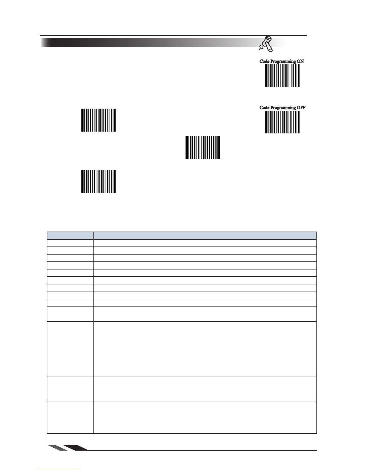
Code Programming On/Off
Read the “Code Programming ON” barcode to activate “Code Programming” function. One or more Code Programming barcodes can be read to
configure the Engine.
If an option or feature needs additional parameters, such as digits, they can be
found at the end of this chapter.
To exit Code Programming, read “Code Programming OFF” or any normal
barcode.
** Code Programming OFF
【Pro CMD:0006000】
Code Programming ON
【Pro CMD:0006010】
The value of code programming can be sent to the Host. For factory default, “No Send Pro
Code Value”, the value
of programming codes will not be sent to the Host; by reading “Send
Pro Code Value”, the reader will send the value of Programming Code to the Host.
**No Send Pro Code Value
【Pro CMD:0002000】
Send Pro Code Value
【Pro CMD:0002010】
Page 27

Page 18
Programming the EngineProgramming the Engine
Code Programming ON
Code Programming OFF
Tools
Illumination
Illumination LED lighting up barcodes are used to capture better images.
There are 4 modes:
“Ill
umination Wink”: LED keeps flashing when reading »
“Illumination Keep ON”: LED keeps on when Power ON »
“Illumination Read ON”: LED keeps on when reading »
“Illumination OFF”: LED is off all the time »
** Illumination Wink
【Pro CMD:0200000】
Illumination Keep ON
【Pro CMD:0200010】
Illumination Read ON
【Pro CMD:0200030】
Illumination OFF
【Pro CMD:0200020】
Page 28

Page 19
Programming the EngineProgramming the Engine
Code Programming ON
Code Programming OFF
Tools
Aiming
There are 3 modes:
“Aim Wink”: LED keeps flashing when reading »
“Aim Keep ON”: LED keeps on when Power ON »
“Aim OFF”: LED is off all the time »
“Sense Mode”: LED is off when reading, on when not reading. »
** Aim Wink
【Pro CMD:0201000】
Aim Keep ON
【Pro CMD:0201010】
Aim OFF
【Pro CMD:0201020】
Sense Mode
【Pro CMD:0201030】
Page 29

Page 20
Programming the EngineProgramming the Engine
Code Programming ON
Code Programming OFF
Tools
Beep
Decoding Beep
Read “Beep ON” to enable all decoding beep denotation and read
“Beep OFF” to disable.
**Beep ON
【Pro CMD:0203010】
Beep OFF
【Pro CMD:0203000】
Decoding Beep Type
**Type 1
【Pro CMD:0203020】
Type 2
【Pro CMD:0203021】
Type 3
【Pro CMD:0203022】
Page 30

Page 21
Programming the EngineProgramming the Engine
Code Programming ON
Code Programming OFF
Tools
Beep
Beep Denotation (Beeper Definitions)
Beep Denotation
low-higher-higher-higher Power ON completed
1 beep successful reading of an ordinary
barcode
2 beeps successful reading of an programming
barcode
3 short low-2 high reading failure
1 long low Unknown Character,
Virtual Keypad
(USB connection)
Decoding Beep Volume
** Loud
【Pro CMD:0203030】
Medium
【Pro CMD:0203031】
Low
【Pro CMD:0203032】
** Beep On
【Pro CMD:0204001】
Beep OFF
【Pro CMD:0204000】
Power On Beep
Page 31

Page 22
Programming the EngineProgramming the Engine
Code Programming ON
Code Programming OFF
Tools
Reading Mode
Hand-held Mode: Pull and keep holding the trigger line to read. Com- »
plete one reading or release the trigger to terminate reading status.
Auto Mode: The ambient luminance change in front of the engine auto- »
matically initiates reading. After completion of reading, the engine goes to idle.
Both luminance chang
e and the Trigger can initiate reading when idle.
Continuous Mode: Pull the Trigger line low to start reading. The engine »
will keep reading. T
o stop, pull trigger line low again.
**Hand-held Mode
【Pro CMD:0302000】
Auto Mode
【Pro CMD:0302010】
Continuous Mode
【Pro CMD:0302020】
Page 32

Page 23
Programming the EngineProgramming the Engine
Code Programming ON
Code Programming OFF
Tools
Reading Timeout and Delay
One Reading Timeout
【Pro CMD:0313000】
Same Barcode Reading Delay
【Pro CMD:0313010】
There are two options available in Same Barcode Reading Delay:
(Multi-reading) Prohibit: The same symbol can be read after delay. »
(Multi-reading) Semi-
prohibit: The same symbol can be read more than once in the delay period »
if ambient illuminati
on is changed, for example the bar code is removed out of reading area and moved
back.
** Multi-reading Semi-prohibit
【Pro CMD:0313020】
Multi-reading Prohibit
【Pro CMD:0313030】
To set One Reading Timeout to 1500ms, read these programming codes:
"Code Programming ON" 1、
"One 2、 Reading Timeout"
Digit Code "1","5","0","0" see Digit Code 3、
"Save Programming" 4、
One Reading Timeo
ut:If
the engine doesn't read any barcode during the
timeout period, it wi
ll stop reading automatically. One Reading Timeout is
valid in Auto mode. The default timeout is 3000ms.
Same Barcode Reading Delay:It is used to avoid misreading on the same
barcode (the same format and message) in a Same Barcode Reading Delay
Time. It is valid only in Auto mode. The default delay is 1500ms.
Page 33

Page 24
Programming the EngineProgramming the Engine
Code Programming ON
Code Programming OFF
Tools
Sensitivity
Sensitivity is how sensitive the engine is to ambient illumination change. »
Sensitivity value is [1 .. 20]
»
The lower the sensit
ivity value is the higher sensitivity will be. The low- »
er the sensitivity value is the smaller illumination change will initiate reading.
High Sensitivity (= 8)
【Pro CMD:0312020】
** Normal Sensitivity (= 11)
【Pro CMD:0312010】
Low Sensitivity (= 14)
【Pro CMD:0312000】
Enhanced Sensitivity (= 5)
【Pro CMD:0312030】
Program Sensitivity
(Min:1, Max:20)
【Pro CMD:0312040】
Page 34

Page 25
Programming the EngineProgramming the Engine
Code Programming ON
Code Programming OFF
Tools
Exposure Imaging Mode
** Normal Exposure Mode
【Pro CMD:0321000】
Reflections Eliminating Mode
【Pro CMD:0321010】
Page 35

Page 26
Programming the EngineProgramming the Engine
Code Programming ON
Code Programming OFF
Tools
Default
Factory Default
Read “Load All Factory Default” to reset all parameters to factory default.
Applicable conditions:
User options programming wrong configuration leads to reading mal- »
function
Forget details of previous programming and start over.
»
**Load All Factory Default
【Pro CMD:0001000】
User Default
All user options can be saved as User Default. It will be restored in non-volatile memory.
Read “Save as User Default” to save all the current user options to be User Default, and erase the previous
User Default. Read “Load User Default”to restore the engine to User Default.
Save as User Default
【Pro CMD:0001150】
Load User Default
【Pro CMD:0001160】
If read “Load All Factory Default”, User Default will still be restored in non-volatile
memory.
Page 36
Page 27
Programming the EngineProgramming the Engine
Code Programming ON
Code Programming OFF
Tools
Query Product Information
Product information could be obtained by reading "Query Product Information"
barcode. The engine will send it to the Host immediately.
“Power ON, Send Product Info”, the engine sends product information through
serial port(only) to the Host after Power ON.
The product information is provided as follows:
Title Remarks
Firmware Ver Device Firmware Version
Build Time Device Firmware Version Establishing Time
Device ID Device Type
App Ver Device Application
Version
uIMG Ver Device uIMG
Version
Date Device Manufacture Date
S/N Device serial number
ESN Use
r-define
d devi
ce serial number
Manufacture ID Device Name
Interface 1 types of communication interfaces:
TTL232(EM3000) or RS232(EM2027), baud rate, parity check, data bits, stop bit
1D Indicate that reading 1D is allowed. Symbols are divided by comma. Additional
features format:
“+” conn
ect features 1.
Min Message Length -> Max Message Length2.
“No Check Digit” or “Check Digit” 3.
“Fixed Length: 2~64
even value”. 4.
It is in this format: Fixed Length: 2 4 6 8 10 12...
2D Indicate that reading 2D is allowed. Symbols are divided by comma.
Additional feature format:
Min Message Length -> Max Message Length
Scan Mode Scan Mode:
Manual Scan
1.
Auto Scan 2.
Continuous Scan3.
Query Product Information
【Pro CMD:0003000】
Power ON, Send Product Info
【Pro CMD:0007010】
**Power ON, Do not Send Product Info
【Pro CMD:0007000】
Page 37

Page 28
RS232 Interface
Introduction
Under RS232 connection, the engine and the Host use the same communication parameters: baud rate, parity
check, data bits select and stop bits select.
Enable RS232 Connection
【Pro CMD:1100000】
Page 38

Page 29
RS232 InterfaceRS232 Interface
Code Programming ON
Code Programming OFF
Tools
Serial Port
Baud Rate
Baud rate is the number of bits of data transmitted per second. Set your scan engine
baud rate to match the baud rate setting of the Host device. Otherwise, they can not
communicate.
The engine supports the following baud rates (The default baud rate is 9600):
**9600
【Pro CMD:0100030】
1200
【Pro CMD:0100000】
2400
【Pro CMD:0100010】
4800
【Pro CMD:0100020】
14400
【Pro CMD:0100040】
19200
【Pro CMD:0100050】
38400
【Pro CMD:0100060】
57600
【Pro CMD:0100070】
115200
【Pro CMD:0100080】
The engine and the Host should use the same serial port parameters: baud rate,
parity check, data bits and stop bits. The sequence is as follows: 9600 (baud rate),
null (parity check), 8 (data bits), 1 (stop bits).
Page 39

Page 30
RS232 InterfaceRS232 Interface
Code Programming ON
Code Programming OFF
Tools
Parity Check
Parity check options should be the same on the engine and the Host.
Select Odd parity: If data has an odd number of 1 bits, the parity bit »
value is set to 0.
Selec
t Even parity:If data has an even number of 1 bits, the parity bit »
value is set to 0.
Selec
t No Parity Check and parity bit will not be sent. »
**No Parity Check
【Pro CMD:0101000】
Even Check
【Pro CMD:0101010】
Odd Check
【Pro CMD:0101020】
Serial Port
Hardware Auto Flow Control(only for 2DScan)
When enabled,2DScan will decide if the data should be sent in accordance with CTS signal level. When it
is low level CTS signal, it means the serial port’s cache memory of receiving end (such as PC) is full and
2DScan will not send data through RS232 until CTS signal is set to high level by receiving end.
When 2DScan is not ready for receiving, it will set RTS signal to low level. When sending end (such as PC)
detects it, it could not send data to 2DScan any more, otherwise the data will be lost.
When disabled, data’s sending and receiving through serial port will not be effected by RTS/CTS signal.
**Disable Hardware Auto Flow Control
【Pro CMD:0104000】
Enable Hardware Auto Flow Control
【Pro CMD:0104010】
Before enabling this function, please be sure that RTS/CTS signal line is contained in RS232
cable. If not, a RS232 communication error will occur.
Page 40

Page 31
RS232 InterfaceRS232 Interface
Code Programming ON
Code Programming OFF
Tools
Data Bits Transmitted
Select data bits transmitted to be 5, 6, 7 and 8. Ensure the selections on
the engine and the Host are the same.
Stop Bits
Stop bit follows every byte to indicate the end of transmission and the start of the next
transmission.
Default 1 stop bit.
**1 Stop Bits
【Pro CMD:0102000】
2 Stop Bits
【Pro CMD:0102010】
Serial Port
** 8 Data Bits
【Pro CMD:0103030】
7 Data Bits
【Pro CMD:0103020】
6 Data Bits
【Pro CMD:0103010】
5 Data Bits
【Pro CMD:0103000】
Page 41

Page 32
USB Interface
Introduction
When only data transmission is needed through USB connection, USB HID-KBW option can
be programmed. It emulates the unit’s transmission as a USB keyboard input. The Host receives
keystrokes of the virtual keyboard. It is “Plug and Play”. There is no driver required.
Page 42

Page 33
USB InterfaceUSB Interface
Code Programming ON
Code Programming OFF
Tools
USB HID-KBW
USB connection (no driver needed) supports simulating the Imager transmission to be a
USB keyboard input. The Host receives keystrokes of the virtual keyboard. It works in
“Plug and Play” base. There is no driver required.
Select USB HID-KBW
【Pro CMD:1100020】
If the input field of the Host allows keyboard input, no software needed to assist HIDKBW input.
Page 43

Page 34
USB InterfaceUSB Interface
Code Programming ON
Code Programming OFF
Tools
USB HID-KBW
The keyboard arrangements and country codes vary in different countries. »
Refer country codes to the table “USB Country Keyboard Types”. Follow the
steps mentioned below to program.
1.“Code Programming ON” »
2.“Select Country Code” »
3. Read digit codes (according to country code) »
4.“Save programming” »
5.“Code Programming OFF” »
Select Country Code
【Pro CMD:1103000】
Emulate Norway keyboard:
1. "Code Programming ON"
2."Select Country Code"
3. Digit code: "1", "5"
4."Save Programming"
5."Code Programming OFF"
USB Country Keyboard Types
Page 44

Page 35
USB Interface
USB HID-KBW
USB Country Keyboard Types
Country/Language Number Country/Language Number
U.S. 0 Netherlands(Dutch) 14
Belgium 1 Norway 15
Brazil 2 Poland 16
Canada(French) 3 Portugal 17
Czechoslovakia 4 Romania 18
Denmark 5 Russia 19
Finland(Swedish) 6 Slovakia 21
France 7 Spain 22
Germany/Austria 8 Sweden 23
Greece 9 Switzerland(German) 24
Hungary 10 Tu
rkey F 25
Israel(Hebrew) 11 Turkey Q 26
Italy 12 U.K 27
Latin-American 13 Japan 28
Page 45

Page 36
USB InterfaceUSB Interface
Code Programming ON
Code Programming OFF
Tools
USB HID-KBW
Unknown Characters, Beep
HID-KBW deems an unknown character to be a character is not included in a
country keyboard type. It may not be able to allocate and send a keystroke, thus lead
to an error beep.
** No Beep, Unkown Character
【Pro CMD:1103030】
Beep, Unkown Character
【Pro CMD:1103031】
Suppose select country keyboard types France (number 7), read a barcode "AÐF".
Since the “Д(0xD0) is not included in France country code, the Imager skip “Д
and transmit “AF”. For factory default, no beep produced. Read “Beep, Unkown
Character”to indicate unknown character.
Page 46

Page 37
USB InterfaceUSB Interface
Code Programming ON
Code Programming OFF
Tools
USB HID-KBW
Emulate ALT + keypad
When enabled, full ASCII characters (0x00~0xff) can be sent over the numeric
keypad regardless country keyboard selections.
“ALT” Make 1、
According to the ASCII value, input the numbers over the numeric keypad 2、
“ALT ”Break 3、
** No Emulate ALT + keypad
【Pro CMD:1103060】
Emulate ALT + keypad
【Pro CMD:1103061】
Too much keystroke emulation slows the sending speed.
Suppose country code “7”, France is selected, and “Emulate ALT + keypad” is
enabled. Barcode message "AÐF" (65/208/70) will be sent as:
1. “ALT make”+ “0,6,5”+“ALT Break”
2. “ALT make”+ “2,0,8”+“ALT Break”
3. “ALT make”+ “0,7,0”+“ALT Break”
Page 47

Page 38
USB InterfaceUSB Interface
Code Programming ON
Code Programming OFF
Tools
USB HID-KBW
Function Key Mapping
When enabled, function characters (0x00~0x1F) are sent as ASCII sequences
over the numeric keypad.
“Ctrl make” 1、
Hit function key 2、
“Ctrl Break” 3、
** No Function Key Mapping
【Pro CMD:1103130】
Function Key Mapping
【Pro CMD:1103140】
USB HID-KBW set to be factory default. Enable “Emulate CTRL + keypad”. Read
barcode “A(tab)F”(0x65/0x09/0x70). The sequence is:
1. Keystroke “A”
2. Input “Ctrl I” by “Ctrl make”, Keystroke “I”, “Ctrl break”
3. Keystroke “F”
For some text editors “Ctrl I” is italic convert. So the output may be “AF”
Enable “Emulate ATL + keypad” will automatically disable “Emulate CTRL +
keypad”
Page 48

Page 39
USB Interface
USB HID-KBW
ASCII Function Key Mapping Table
ASCII(HEX) Function key ASCII(HEX) Function Key
00 2 10 P
01 A 11 Q
02 B 12 R
03 C 13 S
04 D 14 T
05 E 15 U
06 F 16 V
07 G 17 W
08 H 18 X
09 I 19 Y
0A J 1A Z
0B K 1B [
0C L 1C \
0D M 1D ]
0E N 1E 6
0F O 1F .
Page 49

Page 40
USB InterfaceUSB Interface
Code Programming ON
Code Programming OFF
Tools
USB HID-KBW
Keystroke Delay
This parameter sets the delay, in milliseconds, between emulated keystrokes. Scan
programming code below to increase the delay when the Host require a slower transmission of data.
** No Delay
【Pro CMD:1103050】
Short Delay(20ms)
【Pro CMD:1103051】
Long Delay(40ms)
【Pro CMD:1103052】
Caps Lock
The case of the data is inverted regardless of the state of the Caps Lock key on the Host. Lower case and
upper case are converted correspondingly.
** Disable Caps Lock
【Pro CMD:1103010】
Enable Caps Lock
【Pro CMD:1103020】
“Convert Case”,“Emulate ALT + keypad” and “Function Key Mapping”
option prevails “Enable Caps Lock”
“Enable Caps Lock”, barcode message “AbC”is transmitted as “aBc”
Page 50

Page 41
USB InterfaceUSB Interface
Code Programming ON
Code Programming OFF
Tools
USB HID-KBW
Convert Case
The Imager converts all barcode messages to the selected case.
** No Case Conversion
【Pro CMD:1103040】
Convert All to Upper Case
【Pro CMD:1103041】
Convert All to Lower Case
【Pro CMD:1103042】
Read “Convert All to Lower Case”, Barcode message “AbC” is sent as “abc”
Page 51

Page 42
USB InterfaceUSB Interface
Code Programming ON
Code Programming OFF
Tools
USB HID-KBW
Emulate Numeric Keypad
When disable, the whole barcode message will be emulated as keystrokes on main keyboard.
Read “Emulate Numeric Keypad” to enable the function. when “0~9”is of the barcode message,
it will be emulated as keystrokes on numeric keypad. But sign such as “+”“_”“*”“/”“.” is
emulated as keystrokes on main keyboard.
Numeric keypad is normally at the right of a standard keyboard. This function is effected by the current
state of “Num Lock” of Host's numeric keypad. The emulate numeric keypad couldn't control the state
of “Num Lock”. So, if “Num Lock” light off, the output is function key instead of numbers.
** Disable Emulate Numeric Keypad
【Pro CMD:1103110】
Emulate Numeric Keypad
【Pro CMD:1103120】
Check Num Lock light before use this function.
Enable “Emulate ALT + keypad” will automatically disable this function
Enable “Emulate Number Keyboard” and read the “A4.5” barcode. If “Num
Lock” on the Host is ON, the data received will be “A4.5”. If “Num Lock” is OFF,
Host will receive the data from keyboard as follow:
Host receives data “A”. This character is not included in keyboard, thus the data will be
sent as normal.
Next, Host receives data “4” corresponding to the instruction of “Cursor move to
left”.
Then, Host receives data “.” corresponding to the instruction of “delete the character
just back of cursor”.
There is no input generated by data “4” as the data “5” corresponds to NO instructions.
Page 52

Page 43
USB InterfaceUSB Interface
Code Programming ON
Code Programming OFF
Tools
USB DataPipe
This protocol is defined by Newland Reference. A driver has to be installed before
using this protocol to communicate with reader,
The advantage of using this protocol is the fast data transmission. Meanwhile, the
SDK can be easily integrated into the application system.
Select USB DataPipe
【Pro CMD:1100010】
Page 53

Page 44
USB InterfaceUSB Interface
Code Programming ON
Code Programming OFF
Tools
USB COM Port Emulation
When the USB port is connected to Host serial port in order to receive data from
scanner, the model of imitating USB-to-RS232 has to be chosen. Hence, the
engine and the Host must communicate at the same parameters and the parameters
of real serial port and visual serial port must be the same.
Select USB COM Port Emulation
【Pro CMD:1100060】
Page 54

Page 45
USB InterfaceUSB Interface
Code Programming ON
Code Programming OFF
Tools
HID-POS
Introduction
The HID POS interface is recommended for new applications. It can send up to 56
characters in a single USB report and is much faster than keyboard emulation.
Features: »
HID based, no custom driver required »
Much faster than keyboard emulation and traditional RS-232 »
Symbology identifiers (AIM and Hand Held Products) are always con- »
tained in the input report, which uses USB direction names: input (to the PC) and
output (to the device)
Note: HID POS does not require a custom driver installation. However,
a HID
interface on Windows 98 does.
Select HID-POS
【Pro CMD:1100080】
Page 55

Page 46
USB InterfaceUSB Interface
Code Programming ON
Code Programming OFF
Tools
HID-POS
Access the Device in Your Program
CreateFile opens the device as a HID, then ReadFile delivers the scanned data
to the application. Use WriteFile to send data to the device.
For complete information on USB and HID interfaces, please see www.USB.
com.
Getting Scanned Data
After scanning and decoding a bar code, the device sends the following input report:
Bit
Byte 7 6 5 4 3 2 1 0
0 Report ID = 0x02
1 Length of the bar code (field "Decoded Data")
2-57 Decoded Data (1-56)
58-61 Reserved (1-4)
62 Symbology Identifier or N/C:0x00
63 7 6 5 4 3 2 1
Decode
Data
Continued
VID and PID Table
USB uses two numbers to identify a device and find the correct drivers. The first is the VID (Vendor ID),
assigned by the USB Implementers Forum. The vendor ID (VID) is 1EAB (hex). The second is the
PID (Product ID). A range of PIDs is used for each product sub family, so each PID contains a base
number and an interface type (keyboard, COM port, etc.).
Device Interface Type PID(Hex) PID(Dec)
EM2027
Base 0200 512
HID POS 0210 528
2DScan
Base 0100 256
HID POS 011
0 272
Page 56

Page 47
PS/2 Interface
Introduction
PS/2 connection is emulated as an HID-KBW input.
It can only transmit data to the Host, and does not support programming commands from the Host.
It does not support hot plug. Connecting P/S 2 Plugging while the unit is on will cause permanent damage.
Select PS/2
【Pro CMD:1100070】
Page 57

Page 48
Introduction
This chapter lists all the available symbols and provides the programming barcodes to enable/disable them.
Disabling reading of the symbols which do not apply, will improve reading performance. The few abling
reading of the symbols are, the fast the engine will work.
Symbols
Page 58

Page 49
Symbols
Code Programming ON
Code Programming OFF
Tools
General Options
Disable Reading All
Disable Reading All = Allow reading Programming Codes only.
Enable Reading All
Enable Reading All = Enable to read all symbols and Programming Codes.
Enable Reading All
【Pro CMD:0001020】
Enable Reading All 1D
Enable Reading All 1D
【Pro CMD:0001040】
Disable Reading All 1D
Disable Reading All 1D
【Pro CMD:0001030】
Disable Reading All
【Pro CMD:0001010】
Page 59

Page 50
Symbols
Code Programming ON
Code Programming OFF
Tools
General Options
Enable Reading All 2D
Enable Reading All 2D
【Pro CMD:0001060】
Disable Reading All 2D
Disable Reading All 2D
【Pro CMD:0001050】
Page 60

Page 51
Symbols
Code Programming ON
Code Programming OFF
Tools
Code 128
Load Factory Default
** Load Code 128 Factory Default
【Pro CMD:0400000】
Enable/Disable Code 128
Disable Code 128
【Pro CMD:0400010】
** Enable Code 128
【Pro CMD:0400020】
When the engine can not read Code 128, please read“Enable Code 128” and try again.
Page 61

Page 52
Symbols
Code Programming ON
Code Programming OFF
Tools
Code 128
To set Min Message Length of Code 128 to 8 bytes and Max Message Length to 12 bytes,
read these programming codes
“Code Programming ON” 1、
“Select Min Message Length” 2、
Digit Code “8”, see Digit Code 3、
“Save Programming”,see Digit Code 4、
“Select Max Message Length” 5、
Digit Code
“1” 6
、
Digit Code “2” 7、
“
Save Programming” 8、
“Code Programming OFF
” 9、
Select Message Length
It is used to program the valid reading length of Code 128. The engine will
not send barcode message to the Host, if the decoded data length does not
match the valid length.
Code 128 Message Length is defined by “Min. Message Length” and
“Max. Message Length”.
Min Message Length (default: 1)
【Pro CMD:0400030】
Max Message Length (default: 48)
【Pro CMD:0400040】
1D bar code Message Length should not exceed 127 bytes. If Max Message Length is
less than Min Message Length, it means the engine will only support barcodes of the two
lengths. If Max Message Length is equal to Min Message Length, the engine will only support barcodes of the length.
Page 62

Page 53
Symbols
Code Programming ON
Code Programming OFF
Tools
EAN-8
Load Factory Default
** Load UCC/EAN-8 Factory Default
【Pro CMD:0401000】
Enable/Disable UCC/EAN-8
** Enable UCC/EAN-8
【Pro CMD:0401020】
Disable UCC/EAN-8
【Pro CMD:0401010】
Check Digit
UCC/EAN-8 is fixed 8 digits barcode and the last digit is check digit.
**Transmit Check
【Pro CMD:0401040】
Do Not Transmit Check
【Pro CMD:0401030】
Page 63

Page 54
Symbols
Code Programming ON
Code Programming OFF
Tools
EAN-8
2 Digits Addenda Code
Addenda Code is the one to the right of an ordinary code. Picture below
shows an ordinary code with a 2 digits Addenda Code. The left one in blue
lines is an ordinary code. The right one in red lines is the 2 digits Addenda
Code.
** Disable 2 Digits Addenda Code
【Pro CMD:0401050】
Enable 2 Digits Addenda Code
【Pro CMD:0401060】
5 Digits Addenda Code
5 Digits Addenda Code is the one to the right of an ordinary code. Picture below shows an ordinary
code with a 5 digits Addenda Code. The left one in blue lines is an ordinary code. The right one in red
lines is the 5 digits Addenda Code.
** Disable 5 Digits Addenda Code
【Pro CMD:0401070】
Enable5 Digits Addenda Code
【Pro CMD:0401080】
“ Enable 2 Digits Addenda Code “ — read an ordinary code and 2 digits Addenda Code.
“ Enable 5 Digits Addenda Code “ — read an ordinary code and 5 digits Addenda Code.
“Disable 2 Digits Addenda Code “ — read an ordinary code only, and ignore 2 digits
Addenda Code.
1234 567
1234 567
89012
Page 64

Page 55
Symbols
Code Programming ON
Code Programming OFF
Tools
EAN-8
EAN-8 expand to EAN-13
Expand EAN-8 to EAN-13, by adding 5 bytes of “0” to the left, and then transmit.
** Do Not Expand to EAN-13
【Pro CMD:0401090】
Expand to EAN-13
【Pro CMD:0401100】
Page 65

Page 56
Symbols
Code Programming ON
Code Programming OFF
Tools
EAN-13
Load Factory Default
** Load EAN-13 Factory Default
【Pro CMD:0402000】
Disable/EnableEAN-13
** Enable EAN-13
【Pro CMD:0402020】
Disable EAN-13
【Pro CMD:0402010】
Check Digit
** Transmit Check
【Pro CMD:0402040】
Do Not Transmit Check
【Pro CMD:0402030】
Page 66

Page 57
Symbols
Code Programming ON
Code Programming OFF
Tools
5 Digits Addenda Code
2 Digits Addenda Code
“ Enable 2 Digits Addenda Code “ — read an ordinary code and 2 digits Addenda Code.
“ Enable 5 Digits Addenda Code “ — read an ordinary code and 5 digits Addenda Code.
“Disable 2 Digits Addenda Code “ — read an ordinary code only, and ignore 2 digits
Addenda Code.
5 Digits Addenda Code is the one to the right of an ordinary code. Picture below shows an ordinary
code with a 5 digits Addenda Code. The left one in blue lines is an ordinary code. The right one in red
lines is the 5 digits Addenda Code.
Addenda Code is the one to the right of an ordinary code. Picture below
shows an ordinary code with a 2 digits Addenda Code. The left one in blue
lines is an ordinary code. The right one in red lines is the 2 digits Addenda
Code.
** Disable 5 Digits Addenda Code
【Pro CMD:0402070】
Enable5 Digits Addenda Code
【Pro CMD:0402080】
** Disable 2 Digits Addenda Code
【Pro CMD:0402050】
Enable 2 Digits Addenda Code
【Pro CMD:0402060】
1 234567 89012
34
1 234567 89012
45678
EAN-13
Page 67

Page 58
Symbols
Code Programming ON
Code Programming OFF
Tools
UPC-E
Load Factory Default
** Load UPC-E Factory Default
【Pro CMD:0403000】
Disable/Enable UPC-E
** Enable UPC-E
【Pro CMD:0403020】
Disable UPC-E
【Pro CMD:0403010】
When the engine can not read UPC-E, please read “Enable UPC-E” and try again.
Check Digit
UPC-E is fixed 8 digits barcode and the last digit is check digit.
** Transmit Check
【Pro CMD:0403040】
Do Not Transmit Check
【Pro CMD:0403030】
Page 68

Page 59
Symbols
Code Programming ON
Code Programming OFF
Tools
5 Digits Addenda Code
2 Digits Addenda Code
“ Enable 2 Digits Addenda Code “ — read an ordinary code and 2 digits Addenda Code.
“ Enable 5 Digits Addenda Code “ — read an ordinary code and 5 digits Addenda Code.
“Disable 2 Digits Addenda Code “ — read an ordinary code only, and ignore 2 digits
Addenda Code.
** Disable 5 Digits Addenda Code
【Pro CMD:0403070】
Enable 5 Digits Addenda Code
【Pro CMD:0403080】
5 Digits Addenda Code is the one to the right of an ordinary code. Picture below shows an ordinary
code with a 5 digits Addenda Code. The left one in blue lines is an ordinary code. The right one in red
lines is the 5 digits Addenda Code.
** Abort 2 Digits Addenda
【Pro CMD:0403050】
Enable 2 Digits Addenda Code
【Pro CMD:0403060】
Addenda Code is the one to the right of an ordinary code. Picture below
shows an ordinary code with a 2 digits Addenda Code. The left one in blue
lines is an ordinary code. The right one in red lines is the 2 digits Addenda
Code.
UPC-E
0 123456
78
0 123456
78901
Page 69

Page 60
Symbols
Code Programming ON
Code Programming OFF
Tools
UPC-E
Transmit Default “0”
The first byte of UPC-E is default to “0”.
UPC-E Expand to UPC-A
Follow the standard algorithm to expand UPC-E to UPC-A.
**Do Not Expand to UPC-A
【Pro CMD:0403110】
Expand to UPC-A
【Pro CMD:0403120】
** Do Not Transmit “0”
【Pro CMD:0403090】
Transmit “0”
【Pro CMD:0403100】
Page 70

Page 61
Symbols
Code Programming ON
Code Programming OFF
Tools
UPC-A
Load Factory Default
** Load UPC-A Factory Default
【Pro CMD:0404000】
Disable/Enable UPC-A
When the engine can not read UPC-A, please read “Enable UPC-A” and try again.
Check Digit
UPC-A is fixed 13 digits barcode and the last digit is Check Digit.
** Enable UPC-A
【Pro CMD:0404020】
Disable UPC-A
【Pro CMD:0404010】
**Transmit Check
【Pro CMD:0404040】
(Do) Not Transmit Check
【Pro CMD:0404030】
Page 71

Page 62
Symbols
Code Programming ON
Code Programming OFF
Tools
5 Digits Addenda Code
2 Digits Addenda Code
“ Enable 2 Digits Addenda Code “ — read an ordinary code and 2 digits Addenda Code.
“ Enable 5 Digits Addenda Code “ — read an ordinary code and 5 digits Addenda Code.
“Disable 2 Digits Addenda Code “ — read an ordinary code only, and ignore 2 digits
Addenda Code.
** Disable 5 Digits Addenda Code
【Pro CMD:0404070】
Enable 5 Digits Addenda Code
【Pro CMD:0404080】
5 Digits Addenda Code is the one to the right of an ordinary code. Picture below shows an ordinary
code with a 5 digits Addenda Code. The left one in blue lines is an ordinary code. The right one in red
lines is the 5 digits Addenda Code.
** Disable 2 Digits Addenda Code
【Pro CMD:0404050】
Enable 2 Digits Addenda Code
【Pro CMD:0404060】
Addenda Code is the one to the right of an ordinary code. Picture below
shows an ordinary code with a 2 digits Addenda Code. The left one in blue
lines is an ordinary code. The right one in red lines is the 2 digits Addenda
Code.
1 23456 78901
23
1 23456 78901
23456
UPC-A
Page 72

Page 63
Symbols
Code Programming ON
Code Programming OFF
Tools
Transmit Default “0”
The first byte of UPC-A is default to “0”.
UPC-A has the default “0” but it is not printed out, unlike UPC-E. Read “Transmit
0” will add a “0” to transmit.
UPC-A
**Do Not Transmit “0”
【Pro CMD:0404090】
Transmit “0”
【Pro CMD:0404100】
Page 73

Page 64
Symbols
Code Programming ON
Code Programming OFF
Tools
Interleaved 2 of 5
Load Factory Default
** Load Interleaved 2 of 5 Factory Default
【Pro CMD:0405000】
Disable/Enable Interleaved 2 of 5
When the engine can not read Interleaved 2 of 5, please read “Enable Interleaved 2 of 5”
and try again
** Enable Interleaved 2 of 5
【Pro CMD:0405020】
Disable Interleaved 2 of 5
【Pro CMD:0405010】
Page 74

Page 65
Symbols
Code Programming ON
Code Programming OFF
Tools
Select Message Length
It is used to program the valid reading length of Interleaved 2 of 5. The engine
will not send barcode message to the Host, if the decoded data length does not
match the valid length.
Interleaved 2 of 5 Message Length is defined by “Min. Message Length”
and “Max. Message Length”
Interleaved 2 of 5
To set Min Message Length of Interleaved 2 of 5 as 8 bytes, and Max Message length as 12
bytes, read these programming codes:
1. “Code Programming ON”
2. “Select Min Message Length”
3. Digit Code “8”, see Digit Code Appendix (Pxxx)
4. “Save Programming”, see Digit Code Appendix (Pxxx)
5. “Select Max Message Length”
6. Digit Code “1”
7. Digit Code “2”
8. “Save Programming”
9. “Code Programming OFF”
Min Message Length (default: 6)
【Pro CMD:0405030】
Max Message Length (default: 80)
【Pro CMD:0405040】
1D bar code Message Length should not exceed 127 bytes. If Max Message Length is
less than Min Message Length, it means the engine will only support barcodes of the two
lengths. If Max Message Length is equal to Min Message Length, the engine will only support barcodes of the length.
Page 75

Page 66
Symbols
Code Programming ON
Code Programming OFF
Tools
Interleaved 2 of 5
Check Digit
Interleaved 2 of 5 may include Check Digit (not compulsory) following its
barcode messages. It verifies the barcode message.
“NO Check, Transmit All” means to read without check and transmit »
all bytes including barcode message and Check digit.
“Check, Do Not Transmit Check Digit” means to read and check. If »
verification is successful, transmits barcode message; if not, engine will not
send barcode message to the Host.
“Check, Transmit All” means to read and check. If verification is »
successful, transmits all messages; if not, engine will not send barcode message to the Host.
** NO Check, Transmit All
【Pro CMD:0405050】
When “Check, Do Not Transmit Check digit” is enabled and barcode message length
minus one is less than Min Message Length, it will lead to an error.
E.g.:Reading a 4-byte (include check Digit) Interleaved 2 of 5 with the Min Message
Length being 4 bytes and “Check, Do Not Transmit Check digit” enabled leads to an
error.
Check, Do Not Transmit Check Digit
【Pro CMD:0405060】
Check, Transmit All
【Pro CMD:0405070】
The number of Interleaved 2 of 5 barcode bits(check digit contained) must be even. If it is odd, a 0 will
be added as the first digit. The check digit generates automatically when a barcode is produced.
Page 76

Page 67
Symbols
Code Programming ON
Code Programming OFF
Tools
Interleaved 2 of 5
Specified Lengths
Program the engine to read specified lengths or ranges of specified lengths for
Interleaved 2 of 5. The length value must be 3 decimal digits. And the length
value MUST be an even number between 2 to 64.
Read “Enable Specified Length” to enable this feature or “Disable
Specified Length” to disable.
The engine only read Interleaved 2 of 5 which are 12 and 24 bytes.
1. “Code Programming ON”
2. “Enable Specified Length”
3. “Add Code Length”
4. Digit Code “0”,“1”,“2”
5. “Save Programming”
6. “Add code length”
7. Digit Code “0”,“2”,“4”
8. “Save Programming”
9. “Code Programming OFF”
The engine only read Interleaved 2 of 5 between 12 bytes and 24 bytes.
1. “Code Programming ON”
2. “Enable Specified Length”
3. “Add Code Length”
4. Digit Code “0”,“1”,“2”
5. Digit Code “0”,“2”,“4”
6. “Save Programming”
7. “Code Programming OFF”
** Disable Specified Length
【Pro CMD:0405140】
Enable Specified Length
【Pro CMD:0405150】
Add Code Length
【Pro CMD:0405160】
Remove Code Length
【Pro CMD:0405170】
Page 77

Page 68
Symbols
Code Programming ON
Code Programming OFF
Tools
ITF-14
ITF-14 is a fixed length, 14 bytes Interleaved 2 of 5 barcode with Check digit. By
factory default, it is disabled.
When enabled, ITF-14 precedes 14-byte Interleaved 2 of 5 barcode.
**Disable ITF-14
【Pro CMD:0405080】
Enable ITF-14, Do Not Transmit Check Digit
【Pro CMD:0405090】
Enable ITF-14, Transmit Check Digit
【Pro CMD:0405100】
For instance, when ITF-14 is enabled and Interleaved 2 of 5 is disabled, the ITF-14 and 14
bytes Interleaved 2 of 5 with check digit can be read, but other Interleaved 2 of 5 can not.
Page 78

Page 69
Symbols
Code Programming ON
Code Programming OFF
Tools
ITF-6
ITF-6 is a fixed length 6 bytes Interleaved 2 of 5 barcode with check digit.
When enabled, ITF-6 precedes 6-byte Interleaved 2 of 5 barcode.
**Disable ITF-6 User Selection
【Pro CMD:0405110】
ITF-6, Read, Do Not Transmit Check Digit
【Pro CMD:0405120】
ITF-6, Read, Transmit Check Digit
【Pro CMD:0405130】
For instance, when ITF-6 is enabled and Interleaved 2 of 5 is disabled, the ITF-6 and 6
bytes Interleaved 2 of 5 with check digit can be read, but other Interleaved 2 of 5 can not
Page 79

Page 70
Symbols
Code Programming ON
Code Programming OFF
Tools
Code 39
Load Factory Default
** Load Code 39 Factory Default
【Pro CMD:0408000】
Enable/Disable Code 39
When the engine can not read Code 39, please read “Enable Code 39” and try again
Transmit Start & Stop Character
Transmission of “*” can be selected.
** Enable Code 39
【Pro CMD:0408020】
Disable Code 39
【Pro CMD:0408010】
**Transmit Both “*”
【Pro CMD:0408090】
Transmit Neither “*”
【Pro CMD:0408080】
Page 80

Page 71
Symbols
Code Programming ON
Code Programming OFF
Tools
Code 39
Select Message Length
It is used to program the valid reading length of Code 39. The engine will not
send barcode message to the Host, if the decoded data length does not match
the valid length.
Code 39 Message Length is defined by “Min. Message Length” and
“Max. Message Length “.
To set Min Message Length of Code 39 to 8 bytes, and Max Message Length to 12 bytes,
read these programming codes:
1. “Code Programming ON”
2. “Select Min Message Length”
3. Digit Code “8”, see Digit Code
4. “Save Programming”, see Digit Code
5. “Select Max Message Length”
6. Digit Code “1
”
7. Digit Code “2”
8.“Save Programming”
9.“Code Programming OFF”
Min Message Length (default: 1)
【Pro CMD:0408030】
Max Message Length (default: 48)
【Pro CMD:0408040】
1D bar code Message Length should not exceed 127 bytes. If Max Message Length is
less than Min Message Length, it means the engine will only support barcodes of the two
lengths. If Max Message Length is equal to Min Message Length, the engine will only support barcodes of the length.
Page 81

Page 72
Symbols
Code Programming ON
Code Programming OFF
Tools
Code 39
When “Check, Do not Transmit Check digit” is enabled and barcode message length
minus one is less than Min Message Length, it will lead to an error.
E.g.:Reading a 4-byte (include check byte) Code 39 with the Min Message Length being 4
bytes and “Check, Do not transmit Check Digit” enabled leads to an error.
Decode ASCII
Code 39 can include full ASCII characters. For factory default, the engine only decodes part of them.
Read “Full ASCII decode” to decode full ASCII characters.
** NO Check, Transmit All
【Pro CMD:0408050】
Check, Do not transmit Check Digit
【Pro CMD:0408060】
Check, Transmit All
【Pro CMD:0408070】
Check Digit
Code 39 may include Check Digit (not compulsory) following its barcode
message. It verifies the barcode message.
"NO Check, Transmit All" means to read without check and transmit »
all bytes including barcode message and Check Digit.
"Check, Do Not Transmit Check Digit" means to read and check. If »
verification is successful, transmits barcode message; if not, engine will not
send barcode message to the Host.
"Check, Transmit All" means to read and check. If verification is suc- »
cessful, transmits all messages; if not, engine will not send barcode message
to the Host.
**Partial ASCII Decode
【Pro CMD:0408100】
Full ASCII Decode
【Pro CMD:0408110】
Page 82

Page 73
Symbols
Code Programming ON
Code Programming OFF
Tools
Codabar
Load Factory Default
** Load Codabar Factory Default
【Pro CMD:0409000】
Enable/Disable Codabar
When the engine can not read Codabar, please read “Enable Codabar” and try again.
** Enable Codabar
【Pro CMD:0409020】
Disable Codabar
【Pro CMD:0409010】
Page 83

Page 74
Symbols
Code Programming ON
Code Programming OFF
Tools
Codabar
Select Message Length
It is used to program the valid reading length of Codabar. The engine will not
send barcode message to the Host, if the decoded data length does not match
the valid length.
Codabar Message Length is defined by “Min. Message Length” and
“Max. Message Length “.
Min Message Length (default: 2)
【Pro CMD:0409030】
Max Message Length (default: 60)
【Pro CMD:0409040】
1D bar code Message Length should not exceed 127 bytes. If Max Message Length is
less than Min Message Length, it means the engine will only support barcodes of the two
lengths. If Max Message Length is equal to Min Message Length, the engine will only support barcodes of the length.
Page 84

Page 75
Symbols
Code Programming ON
Code Programming OFF
Tools
Codabar
When “Check, Do not Transmit Check digit” is enabled and barcode message length
minus one is less than Min Message Length, it will lead to an error.
E.g.:Reading a 4-byte (include check byte) Codabar with the Min Message Length being 4
bytes and “Check, Do not transmit Check Digit” enabled leads to an error.
** NO Check, Transmit All
【Pro CMD:0409050】
Check, Do not transmit Check Digit
【Pro CMD:0409060】
Check, Transmit All
【Pro CMD:0409070】
Check Digit
Codabar may include Check Digit (not compulsory) following its barcode
message. It verifies the barcode message.
"NO Check, Transmit All" means to read without check and transmit »
all bytes including barcode message and Check Digit.
"Check, Do Not Transmit Check Digit" means to read and check. If »
verification is successful, transmits barcode message; if not, engine will not
send barcode message to the Host.
"Check, Transmit All" means to read and check. If verification is suc- »
cessful, transmits all messages; if not, engine will not send barcode message
to the Host.
Page 85

Page 76
Symbols
Code Programming ON
Code Programming OFF
Tools
Codabar
Transmit Start & Stop Character
Codabar uses either one of “A”, “B”, “C” and “D” as the start
character and the stop character. Transmission of them can be selected.
**Transmit Both Start & Stop Character
【Pro CMD:0409090】
Transmit Neither Start & Stop Character
【Pro CMD:0409080】
**Use ABCD/ABCD As Start & Stop Character
【Pro CMD:0409100】
Use ABCD/TN*E As Start & Stop Character
【Pro CMD:0409110】
**Use Upper Letter
【Pro CMD:0409120】
Use Lower Letter
【Pro CMD:0409130】
Page 86

Page 77
Symbols
Code Programming ON
Code Programming OFF
Tools
Code 93
Load Factory Default
** Load Code 93 Factory Default
【Pro CMD:0410000】
Enable /Disable Code 93
When the engine can not read Code 93, please read “Enable Code 93” and try again.
** Disable Code 93
【Pro CMD:0410010】
Enable Code 93
【Pro CMD:0410020】
Page 87

Page 78
Symbols
Code Programming ON
Code Programming OFF
Tools
Select Message Length
It is used to program the valid reading length of Code 93. The engine will not
send barcode message to the Host, if the decoded data length does not match
the valid length.
Code 93 Message Length is defined by “Min. Message Length” and “Max.
Message Length .”
Code 93
To set Min Message Length of Code 93 to 8 bytes and Max Message Length to 12 bytes,
read these programming codes:
1.“Code Programming ON”
2.“Select Min Message Length”
3. Digit Code “8”, see Digit Code
4.“Save Programming”, see Digit Code
5.“Select Max Message Length”
6. Digit Code “1”
7. Digit Code “2”
8.“Save Programming”
9.“Code Programming OFF”
Min Message Length (default: 1)
【Pro CMD:0410030】
Max Message Length (default: 48)
【Pro CMD:0410040】
1D bar code Message Length should not exceed 127 bytes. If Max Message Length is
less than Min Message Length, it means the engine will only support barcodes of the two
lengths. If Max Message Length is equal to Min Message Length, the engine will only support barcodes of the length.
Page 88

Page 79
Symbols
Code Programming ON
Code Programming OFF
Tools
Code 93
NO Check, Transmit All
【Pro CMD:0410050】
** Check, Do not transmit Check Digit
【Pro CMD:0410060】
Check, Transmit All
【Pro CMD:0410070】
Check Digit
Code 93 may include Check Digits (not compulsory) following its barcode
message. The two digits verify the barcode message.
"NO Check, Transmit All" means to read without check and transmit »
all bytes including barcode message and Check Digits.
"Check, Do Not Transmit Check Digit" means to read and check. If »
verification is successful, transmits barcode message; if not, engine will not
send barcode message to the Host.
"Check, Transmit All" means to read and check. If verification is suc- »
cessful, transmits all messages; if not, engine will not send barcode message
to the Host.
When “Check, Do not Transmit Check digit” is enabled and barcode message length
minus one is less than Min Message Length, it will lead to an error.
E.g.:Reading a 4-byte (include check byte) Code 93 with the Min Message Length being 4
bytes and “Check, Do not transmit Check Digit” enabled leads to an error.
Page 89

Page 80
Symbols
Code Programming ON
Code Programming OFF
Tools
UCC/EAN-128
Load Factory Default
** Load UCC/EAN-128 Factory Default
【Pro CMD:0412000】
Enable/Disable UCC/EAN-128
When the engine can not read UCC/EAN-128, please read “Enable UCC/EAN-128” and
try again.
** Enable UCC/EAN-128
【Pro CMD:0412020】
Disable UCC/EAN-128
【Pro CMD:0412010】
Page 90

Page 81
Symbols
Code Programming ON
Code Programming OFF
Tools
GS1 Databar
Load Factory Default
** Load GS1 Databar Factory Default
【Pro CMD:0413000】
Enable/Disable GS1 Databar
When the engine can not read GS1 Databar, please read “Enable GS1 Databar” and try
again.
** Enable GS1 Databar
【Pro CMD:0413020】
Disable GS1 Databar
【Pro CMD:0413010】
Transmit AI(01) Character
** Transmit AI(01) Character
【Pro CMD:0413060】
Do not Transmit AI(01) Character
【Pro CMD:0413050】
Page 91

Page 82
Symbols
Code Programming ON
Code Programming OFF
Tools
EAN·UCC Composite
Load Factory Default
** Load EAN·UCC Composite Factory Default
【Pro CMD:0414000】
Enable/Disable EAN·UCC Composite
When the engine can not read EAN·UCC Composite, please read “Enable EAN·UCC
Composite” and try again.
Enable EAN·UCC Composite
【Pro CMD:0414020】
** Disable EAN·UCC Composite
【Pro CMD:0414010】
Enable UPC/EAN Composite
【Pro CMD:0414040】
** Disable UPC/EAN Composite
【Pro CMD:0414030】
Page 92

Page 83
Symbols
Code Programming ON
Code Programming OFF
Tools
Code 11
Load Factory Default
** Load Code 11 Factory Default
【Pro CMD:0415000】
Enable/Disable Code 11
When the engine can not read Code 11, please read “Enable Code 11” and try again.
Enable Code 11
【Pro CMD:0415020】
** Disable Code 11
【Pro CMD:0415010】
Page 93

Page 84
Symbols
Code Programming ON
Code Programming OFF
Tools
Code 11
Select Message Length
It is used to program the valid reading length of Code 11. The engine will not
send barcode message to the Host, if the decoded data length does not match
the valid length.
Code 11 Message Length is defined by “Min. Message Length” and “Max.
Message Length .”
To set Min Message Length of Code11 to 8 bytes and Max Message Length to 12 bytes,
read these programming codes:
1.“Code Programming ON”
2.“Select Min Message Length”
3. Digit Code “8”, see Digit Code
4.“Save Programming”, see Digit Code
5.“Select Max Message Length”
6. Digit Code “1”
7. Digit Code “2”
8.“Save Programming”
9.“Code Programming OFF”
Min Message Length (default: 4)
【Pro CMD:0415030】
Max Message Length (default: 48)
【Pro CMD:0415040】
1D bar code Message Length should not exceed 127 bytes. If Max Message Length is
less than Min Message Length, it means the engine will only support barcodes of the two
lengths. If Max Message Length is equal to Min Message Length, the engine will only support barcodes of the length.
Page 94

Page 85
Symbols
Code Programming ON
Code Programming OFF
Tools
Code 11
When “Check, Do not Transmit Check digit” is enabled and barcode message length
minus one is less than Min Message Length, it will lead to an error.
E.g.:Reading a 4-byte (include check byte) Code 11 with the Min Message Length being 4
bytes and “Check, Do not transmit Check Digit” enabled leads to an error.
NO Check, Transmit All
【Pro CMD:0415050】
** Single Check Digit,MOD11
【Pro CMD:0415060】
Double Check Digits, MOD11/MOD11
【Pro CMD:0415070】
Double Check Digits, MOD11/MOD9
【Pro CMD:0415080】
Single Check Digit MOD11(Len <= 10)
Double Check Digits MOD11/MOD11 (Len > 10)
【Pro CMD:0415090】
Single Check Digit MOD11 (Len <= 10)
Double Check Digits MOD11/MOD9 (Len > 10)
【Pro CMD:0415100】
Do not transmit Check Digit
【Pro CMD:0415110】
** Transmit Check Digit
【Pro CMD:0415120】
Check Digit
Code 11 may include Check Digit (not compulsory) following its barcode message.
It verifies the barcode message.
"NO Check, Transmit All" means to read without check and transmit all »
bytes including barcode message and Check Digit.
"Check, Do Not Transmit Check Digit" means to read and check. If verifica- »
tion is successful, transmits barcode message; if not, engine will not send barcode
message to the Host.
"Check, Transmit All" means to read and check. If verification is successful, »
transmits all messages; if not, engine will not send barcode message to the Host.
Page 95

Page 86
Symbols
Code Programming ON
Code Programming OFF
Tools
ISBN
Load Factory Default
** Load ISBN Factory Default
【Pro CMD:0416000】
Enable/Disable ISBN
Enable ISBN
【Pro CMD:0416020】
** Disable ISBN
【Pro CMD:0416010】
** Transmit 13 digits
【Pro CMD:0416030】
Transmit 10 digits
【Pro CMD:0416040】
Transmit
When the engine can not read ISBN, please read “Enable ISBN” and try again.
Page 96

Page 87
Symbols
Code Programming ON
Code Programming OFF
Tools
Industrial 2 of 5
Load Factory Default
** Load Industrial 2 of 5 Factory Default
【Pro CMD:0417000】
Enable/Disable Industrial 2 of 5
Enable Industrial 2 of 5
【Pro CMD:0417020】
** Disable Industrial 2 of 5
【Pro CMD:0417010】
When the engine can not read Industrial 2 of 5, please read “ Enable Industrial 2 of 5” and try
again.
Page 97

Page 88
Symbols
Code Programming ON
Code Programming OFF
Tools
Industrial 25
Min Message Length (default: 6)
【Pro CMD:0417030】
Max Message Length (default:48)
【Pro CMD:0417040】
Select Message Length
1D bar code Message Length should not exceed 127 bytes. If Max Message Length is
less than Min Message Length, it means the engine will only support barcodes of the two
lengths. If Max Message Length is equal to Min Message Length, the engine will only support barcodes of the length.
It is used to program the valid reading length of Industrial 25. The engine will
not send barcode message to the Host, if the decoded data length does not
match the valid length.
Industrial 2 of 5 Message Length is defined by “ Min. Message Length” and
“Max. Message Length .”
To set Min Message Length of Industrial 25 to 8 bytes and Max Message Length to 12
bytes, read these programming codes:
1.“Code Programming ON”
2.“Select Min Message Length”
3. Digit Code “8”, see Digit Code
4.“Save Programming”, see Digit Code
5.“Select Max Message Length”
6. Digit Code “1”
7. Digit Code “2”
8.“Save Programming”
9.“Code Programming OFF”
Page 98

Page 89
Symbols
Code Programming ON
Code Programming OFF
Tools
Industrial 25
** NO Check, Transmit All
【Pro CMD:0417050】
Check, Do Not Transmit Check Digit
【Pro CMD:0417060】
Check, Transmit All
【Pro CMD:0417070】
Check Digit
Industrial 25 may include Check Digit (not compulsory) following its barcode
message. It verifies the barcode message.
"NO Check, Transmit All" means to read without check and transmit all »
bytes including barcode message and Check Digit.
"Check, Do Not Transmit Check Digit" means to read and check. If verifica- »
tion is successful, transmits barcode message; if not, engine will not send barcode
message to the Host.
"Check, Transmit All" means to read and check. If verification is successful, »
transmits all messages; if not, engine will not send barcode message to the Host.
When “Check, Do not Transmit Check digit” is enabled and barcode message length
minus one is less than Min Message Length, it will lead to an error.
E.g.:Reading a 4-byte (include check byte) Industrial 25 with the Min Message Length
being 4 bytes and “Check, Do not transmit Check Digit” enabled leads to an error.
Page 99

Page 90
Symbols
Code Programming ON
Code Programming OFF
Tools
Standard 2 of 5
Load Factory Default
** Load Standard 2 of 5 Factory Default
【Pro CMD:0418000】
Enable/Disable Standard 2 of 5
When the engine can not read Standard 2 of 5, please read “ Enable Standard 2 of 5” and try
again.
Enable Standard 2 of 5
【Pro CMD:0418020】
** Disable Standard 2 of 5
【Pro CMD:0418010】
Page 100

Page 91
Symbols
Code Programming ON
Code Programming OFF
Tools
Standard 25
Min Message Length (default: 6)
【Pro CMD:0418030】
Max Message Length (default:48)
【Pro CMD:0418040】
Select Message Length
1D bar code Message Length should not exceed 127 bytes. If Max Message Length is
less than Min Message Length, it means the engine will only support barcodes of the two
lengths. If Max Message Length is equal to Min Message Length, the engine will only support barcodes of the length.
It is used to program the valid reading length of Standard 2 of 5. The engine will
not send barcode message to the Host, if the decoded data length does not
match the valid length.
Standard 2 of 5 Message Length is defined by “Min. Message Length” and
“Max. Message Length .”
To set Min Message Length of Standard 2 of 5 to 8 bytes and Max Message Length to 12
bytes, read these programming codes:
1.“Code Programming ON”
2.“Select Min Message Length”
3. Digit Code “8”, see Digit Code
4.“Save Programming”, see Digit Code
5.“Select Max Message Length”
6. Digit Code “1”
7. Digit Code “2”
8.“Save Programming”
9.“Code Programming OFF”
 Loading...