

Page 1

© 2018 Integrated Device Technology, Inc. 1 November 1, 2018
ZWIR4532 Evaluation Kit User Manual
Description
The ZWIR4532 Development Kit is a set of three circuit boards
intended as an evaluation and application development platform for
the ZWIR4532 6LoWPAN module. Each Development Board
provides an USB interface and an optional single Ethe rnet interface
to connect with the user's PC. The USB is used as a virtual COM
port and provides the power supply for JTAG programming and
debugging. The Ethernet interface is provided to easily integrate
the 6LoWPAN network into existing network infrastructure. Push
buttons and LEDs are available as an on-board user interface. The
application circuitry can be easily prototyped.
The Development Kit provides firmware libraries and example
programs. Firmware libraries include an operating system, IDT's
mesh-routing-enabled 6LoWPAN stack, IP-Security (IPSec) and
Internet Key Exchange version 2 (IKEv2) protocol support, as well
as support for over-the-air (OTA) updates and different peripheral
libraries. Ethernet gateway firmware is provided with the kit,
allowing transparent integration of sensor networks into existing
Ethernet networks.
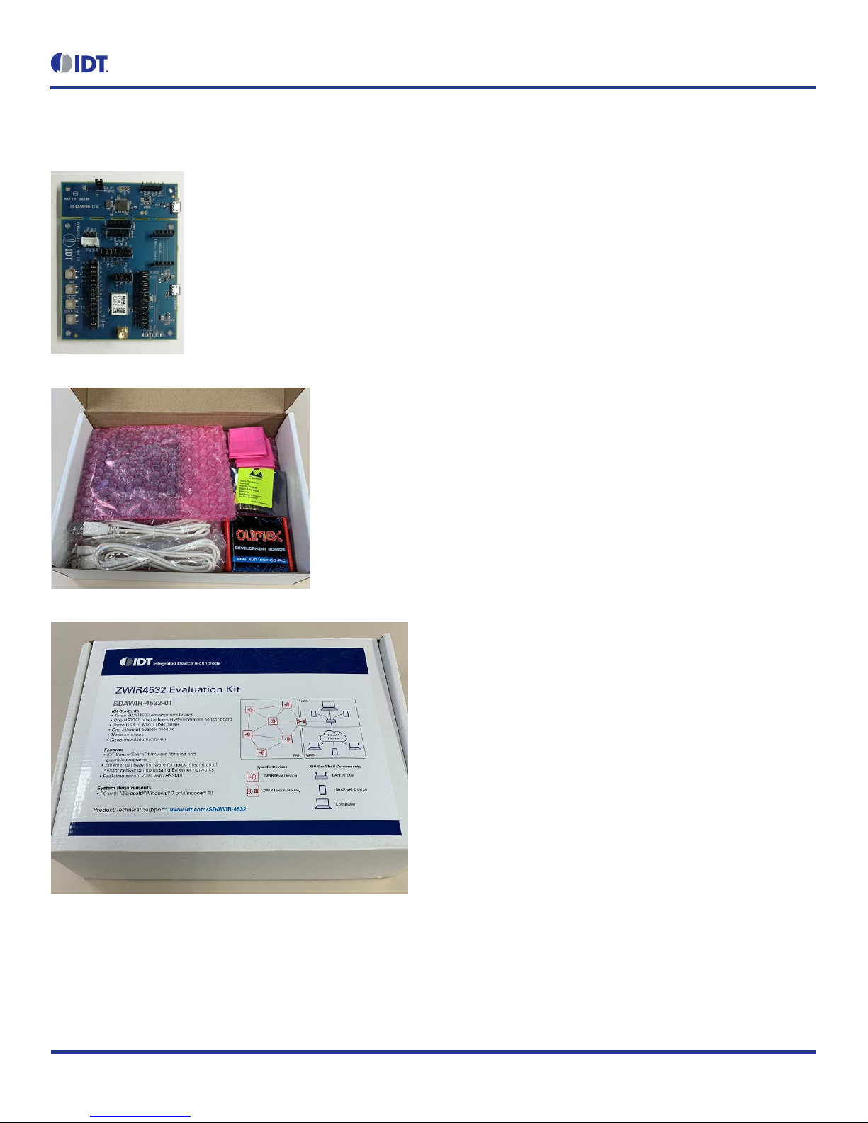
Kit Contents
3 ZWIR4532 development boards
3 HS3001 Humidity and Temperature sensors
3 USB to Micro USB cables
3 antennas
1 Ethernet adapter
Features
IDT SensorShare firmware libraries and example programs
License-free 868/915 MHz frequency bands
IPv6 module addressing
4 channels in EU mode; 10 channels in US mode
Over-the-air update (OTAU) functionality
Mesh connectivity
HS3001 Humidity and Temperature Sensor with I2C interface
in the Sensor Cube
• RH accuracy: ±1.5% RH typical (10% to 90% RH, 25°C)
• Fast RH response time (typical: 6 seconds)
• Temperature sensor accuracy: ±0.2°C (typ.) at -10°C to
+80°C
Related datasheets are available online:
• ZWIR4532: www.idt.com/ZWIR4532
• HS3001: www.idt.com/HS3001
• ENC28J60H Ethernet Adapter
https://www.olimex.com/Products/Modules/Ethernet/ENC2
8J60-H/resources/ENC28J60-H.pdf
• Microchip AT86RF212 Transceiver
http://ww1.microchip.com/downloads/en/DeviceDoc/doc81
68.pdf
• ST Micro STM32L071 MCU
https://www.st.com/resource/en/datasheet/stm32l071v8.pdf
Page 2
ZWIR4532 Evaluation Kit User Manual
© 2018 Integrated Device Technology, Inc. 2 November 1, 2018
!
!
Important Notes
Disclaimer
Integrated Device Technology, Inc. and its affiliated companies (herein referred to as “IDT”) shall not be liable for any damages arising out of defects resulting from
(i) delivered hardware or software
(ii) non-observance of instructions contained in this manual and in any other documentation provided to user, or
(iii) misuse, abuse, use under abnormal conditions, or alteration by anyone other than IDT.
TO THE EXTENT PERMITTED BY LAW, IDT HEREBY EXPRESSLY DISCLAIMS AND USER EXPRESSLY WAIVES ANY AND ALL WARRAN TIES, WHETHER
EXPRESS, IMPLIED, OR STATUTORY, INCLUDING, WITHOUT LIMITATION, IMPLIED WARRANTIES OF MERCHANTABILITY AND OF FITNESS FOR A
PARTICULAR PURPOSE, STATUTORY WARRANTY OF NON-INFRINGEMENT, AND ANY OTHER WARRANTY THAT MAY ARISE BY REASON OF USAGE
OF TRADE, CUSTOM, OR COURSE OF DEALING.
Restrictions in Use
IDT’s SDAWIR03 Demons trati on Kit, c onsist ing of the 6LoWPAN-WiFi Hub, Sens or Cube(s ), AC/DC W all Mou nt Adapters , Hose; USB and HDMI adapters, and
the IDT Demo Software, are designed to provide a quick s etup for tak ing F low, RH%, and temperatu re meas urements wit h the FS 2012 and HS3001 onl y. IDT’ s
SDAWIR03 Demonstration Kits and IDT Demo Software must not be used for any mission-critical applications, end-customer products, or measurement reference
source.
Important Safety Warning: These procedures can result in high currents, which can cause severe injury or death
and/or equipment damage. Only trained professional staff shoul d connect external equipment a nd operate the software.
Important Equipment Warning: Ensure the correct connection of all cables. Supplying the board using the wrong
polarity could result in damage to the board and/or the equipment. Check that all jumpers have been removed from
the board before applying power.
Contents
1. ZWIR4532 Evaluation Kit Components ........................................................................................................................................................4
2. Setup ............................................................................................................................................................................................................5
2.1 Computer Requirements .....................................................................................................................................................................5
2.2 Setting the Evaluation Kit to Interface the Computer ...........................................................................................................................5
2.3 Evaluation Kit Board Connections .......................................................................................................................................................6
2.3.1 Antenna ................................................................................................................................................................................6
2.3.2 Ethernet Connector ..............................................................................................................................................................7
2.3.3 FS2012 Flow Sensor ............................................................................................................................................................7
2.3.4 IDT Sensor Stick ...................................................................................................................................................................7
2.3.5 Grove Sensor .......................................................................................................................................................................8
2.3.6 User Switch Connections .....................................................................................................................................................8
2.3.7 Reset and Boot Select Switch ..............................................................................................................................................8
2.3.8 User LED Connections .........................................................................................................................................................8
Page 3

ZWIR4532 Evaluation Kit User Manual
© 2018 Integrated Device Technology, Inc. 3 November 1, 2018
2.3.9 Miscellaneous Jumpers ........................................................................................................................................................9
2.3.10 Jumper Locations on the PCB ............................................................................................................................................10
2.4 Kit Power-Off and Operation .............................................................................................................................................................11
3. Schematics .................................................................................................................................................................................................11
4. Integrated Development Environment (IDE) Setup and Configuration .......................................................................................................20
4.1 Download Required Files ..................................................................................................................................................................20
4.2 Installing CrossWorks for ARM and Obtaining an Evaluation Lic en se ..............................................................................................20
4.3 Setting Up Required Libraries and the ZWIR4532 Board Support Package .....................................................................................20
5. Hello World Test Program ..........................................................................................................................................................................21
5.1 Creating a New Project ......................................................................................................................................................................21
5.2 Compiling, Loading and Executing the Project ..................................................................................................................................21
6. Ordering Information ...................................................................................................................................................................................22
7. Revision History ..........................................................................................................................................................................................22
List of Figures
Figure 1. Evaluation Kit Board Connections .......................................................................................................................................................6
Figure 2. Jumper Locations ..............................................................................................................................................................................10
Page 4
ZWIR4532 Evaluation Kit User Manual
© 2018 Integrated Device Technology, Inc. 4 November 1, 2018
1. ZWIR4532 Evaluation Kit Components
Page 5
ZWIR4532 Evaluation Kit User Manual
© 2018 Integrated Device Technology, Inc. 5 November 1, 2018
2. Setup
2.1 Computer Requirements
Windows 7, Windows 8 and Windows 10; 32-bit and 64-bit are supported. The selection of the development program may limit these choices.
2.2 Setting the Evaluation Kit to Interface the Computer
The connection to the evaluation kit is via the computers USB port operating as a serial COMx device. This driver needs to be installed prior to
plugging this Evaluation Kit into the PC. ST Micro provides the driver to do this.
1. Connect to www.st.com
2. In search tab in the upper right corner enter ST-LINK/V2.
3. Click on the STSW-LIN009 option.
4. On the bottom of the page, select the Get Software option and follow the instructions.
5. ST Micro will ask for some information to execute the download.
6. Unzip the download.
7. Execute the resulting .bat file to permit installing the correct version (32-bit or 64-bit).
When the evaluation kit is plugged into the PC, the COM LE D on the Programming Link part of the board will illuminate:
Flashing indicates the USB connection is not correct
Continuously on indicates a working USB connection
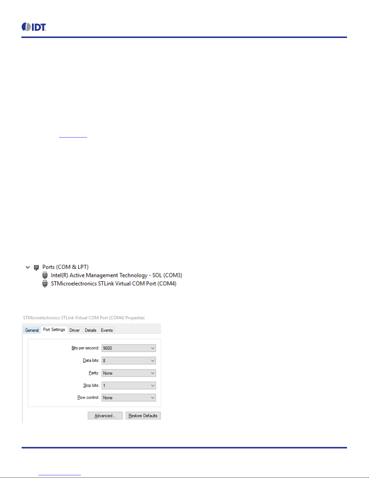
The Control Panel and the Device Manager option on the PC will show the connection and the COM port being used. For example, this shows
a COM4 connection:
Typical port settings will default to:
.
Page 6

ZWIR4532 Evaluation Kit User Manual
© 2018 Integrated Device Technology, Inc. 6 November 1, 2018
I2C Sensor
Grove
Antenna SMA Connector
User Switches
Boot Select
Auxiliary Power via USB cable. Use
board is
separated from the EV Kit board
Ethernet Adapter connector
Indicator LEDs
User LED1
Various
the EV Kit setup
2.3 Evaluation Kit Board Connections
Figure 1. Evaluation Kit Board Connections
Connectors:
IDT FS2012
IDT Sensor Stick
Jumpers to alter
JTAG programming connection.
Only used if the two sections
are separated
USB control connection and
kit power
only when programming
Reset
2.3.1 Antenna
The antenna is to be 50Ω and examples are supplied in the evaluation kit. There is no matching ne twork on the evaluation kit PCB if matching
is needed for other antennas–this has to be done after the SMA connector.
3.3V to ZWIR4532
3.3V to Sensors
USB 5V input
User LED2
Page 7

ZWIR4532 Evaluation Kit User Manual
© 2018 Integrated Device Technology, Inc. 7 November 1, 2018
2.3.2 Ethernet Connector
The ZWIR4532 accepts the Ethernet expansion module ENC28J60-G (supplied in the evaluation kit).
Ethernet Connector
Pin Function Via Jumper ZWIR4532 Pad Function
J18-1 SCK J27 16 A5
J18-2 MOSI J29 34 A7
J18-3 MISO J28 33 A6
J18-4 WOL NC --- ---
J18-5 INT J26 14 A3
J19-5 (6) CLKOUT NC --- --J19-4 (7) CS J25 14 A4
J19-3 (8) RST J24 6 A1
J19-2 (9) GND --- --- ---
J19-1 (10) 3.3V --- --- ---
2.3.3 FS2012 Flow Sensor
FS2012 Flow Sensor
Pin Function Via Jumper ZWIR4532 Pad Function
J20-1 VDD 5V (USB) --- --- --J20-2 I2C – SDA J12 43 B7
J20-3 I2C – SCL J11 42 B6
J20-4 GND --- --- --J20-5 NC --- --- --J20-6 VOUT Resistors R22, R23; J34 38 B1
2.3.4 IDT Sensor Stick
IDT Sensor Stick
Pin Function Via Jumper ZWIR4532 Pad Function
J36-1 VDD 5V (USB) --- --- --J36-2 GND --- --- --J36-3 3.3V Sensors --- --- --J36-4 I2C – SDA J12 43 B7
J36-5 I2C – SCL J11 42 B6
5 NC --- --- ---
Page 8

ZWIR4532 Evaluation Kit User Manual
© 2018 Integrated Device Technology, Inc. 8 November 1, 2018
2.3.5 Grove Sensor
Grove Sensor
Pin Function Via Jumper ZWIR4532 Pad Function
J21-1 I2C – SCL J11 42 B6
J21-2 I2C – SDA J12 43 B7
J21-3
J21-4 GND --- --- ---
VDD 5V (USB) or 3.3V
Sensor
J55 (next to
connector)
--- ---
2.3.6 User Switch Connections
Switch Function Via Jumper ZWIR4532 Pad Function
SW1 N.O. to GND
Soft pull-up to 3.3V
SW2 N.O. to 3.3V
Soft pull-down to GND
J33 11 A9
J43 7 A0
2.3.7 Reset and Boot Select Switch
Switch Function ZWIR4532 Pad Function
SW3 RESET N.O. to GND 8 RST
SW4 BOOT_SEL N.O. to 3.3V 13 BSEL
2.3.8 User LED Connecti ons
LED Function Via Jumper ZWIR4532 Pad Function
LED1 High Level is LED ON J31 30 A11
LED2 High Level is LED ON J43 29 A12
Page 9

ZWIR4532 Evaluation Kit User Manual
© 2018 Integrated Device Technology, Inc. 9 November 1, 2018
2.3.9 Miscellaneous J umpers
Signals which are not committed to a function are connected to dual-row jumpers. The pin not connected to the ZWIR4532 is a no connection.
Jumper ZWIR4532 Pad Function
J30 23 DIG1
J41 22 DIG3
J56 21 DIG4
J39 5 A2
J45 28 A15
J46 35 B2
J47 40 B3
J10 19 B5
J48 32 B8
J49 31 B9
J50 36 B10
J51 27 B14
J52 2 PC13
J7 (connects 32.768kHz time crystal) 3 PC14
J8 (connects 32.768kHz time crystal) 4 PC15
Page 10

ZWIR4532 Evaluation Kit User Manual
© 2018 Integrated Device Technology, Inc.
10
November 1, 2018
2.3.10 Jumper L ocations on the PCB
Figure 2. Jumper Locations
Page 11

ZWIR4532 Evaluation Kit User Manual
© 2018 Integrated Device Technology, Inc.
11
November 1, 2018
2.4 Kit Power-Off and Operation
The ZWIR4532 evaluation kit wil l show as a USB connecte d item. It is best to do a USB eject of t he device and then extract the U SB cable from
the PC.
If the evaluation kit boards have been separated and the Auxiliary USB power connector is being used (no true USB connection to the PC),
simply unplug the cable to power off the evaluation kit.
3. Schematics
Page 12

ZWIR4532 Evaluation Kit User Manual
© 2018 Integrated Device Technology, Inc.
12
November 1, 2018
Page 13

ZWIR4532 Evaluation Kit User Manual
© 2018 Integrated Device Technology, Inc.
13
November 1, 2018
Page 14

ZWIR4532 Evaluation Kit User Manual
© 2018 Integrated Device Technology, Inc.
14
November 1, 2018
Page 15

ZWIR4532 Evaluation Kit User Manual
© 2018 Integrated Device Technology, Inc.
15
November 1, 2018
Page 16

ZWIR4532 Evaluation Kit User Manual
© 2018 Integrated Device Technology, Inc.
16
November 1, 2018
Page 17

ZWIR4532 Evaluation Kit User Manual
© 2018 Integrated Device Technology, Inc.
17
November 1, 2018
Page 18

ZWIR4532 Evaluation Kit User Manual
© 2018 Integrated Device Technology, Inc.
18
November 1, 2018
Page 19

ZWIR4532 Evaluation Kit User Manual
© 2018 Integrated Device Technology, Inc.
19
November 1, 2018
Page 20

ZWIR4532 Evaluation Kit User Manual
© 2018 Integrated Device Technology, Inc.
20
November 1, 2018
4. Integrated Development Environment (IDE) Setup and Configuration
This document assumes Rowley CrossWorks for ARM is a commercial toolchain available for Windows and Linux. It provides an integrated
development environment (IDE) and a debugger. IDT provides board support packages for ZWIR45xx modules to allow for quick and easy
project setup.
4.1 Download Required Files
1. Download CrossStudio from https://www.rowley.co.uk/arm/index.htm.
2. Download ZWIR4532 Firmware Package.zip from IDT.com and unzip to a directory of your choice.
3. Download ST-Link Drivers from ST.com.
4.2 Installi ng C rossWorks for ARM and Obtaini ng an E valuation License
1. Run the installation. Note that the installation requires administrator privileges.
2. Start the CrossStudio IDE.
3. From the main menu bar, select “Tools” “License Manager”.
4. Choose “Evaluate Crossworks”.
5. Select “Primary operating system disk” as the item to which to lock your license.
6. Click on the “Send e-mail” button and wait for reception of your activation key by email –note that this may take some time.
7. After reception of the activation, copy the email contents to the clipboard.
8. Go back to CrossStudio and open the License Manager again .
9. Choose “Activate CrossWorks”.
10. Paste the clipboard contents in the “Enter activation key” textbox (usually the clipboard content is already there).
11. Click on “Install License”.
12. Click “Close”.
4.3 Setting U p R equired Libraries and the ZWIR4532 Board Support Package
1. From the main menu bar, select “Tools” “Package Manager”.
2. Find the “STM32 CPU Support Package” and mark for installation by double-clicking or right-clicking and “Install Selected Package”.
3. Click “Next” button twice followed by “Finish”.
4. From the main menu bar, select “Tools” “Packages” “Manually Install Packages…”.
5. Navigate to the directory where the ZWIR4532 Firmware Package has been unzipped.
6. Select the “ZWIR4532 Board Support Package” and click open.
Page 21

ZWIR4532 Evaluation Kit User Manual
© 2018 Integrated Device Technology, Inc.
21
November 1, 2018
5. Hello World Test Program
5.1 Creating a New Project
1. From the main menu, select “File” “New Project”.
2. Select “6LoWPAN project template for ZWIR4532 modules”.
3. Modify the project name and chose a directory where the project will be stored.
4. Click “Next”.
5. Select/deselect libraries as shown below and click “ Next”.
6. Click “Finish”.
5.2 Compiling, Loading and Executing the Pr oject
1. The project generated above already includes some functional code that may be left unchanged for this test.
2. Compile the project by pressing “F7” or right-click on the project name in th e project explorer and select “Build”.
3. Ensure the development kit is connected through the programming link USB connector.
4. From the main menu, select “”Target” “Connect” “STLink/V2”.
5. Press “F5” to load and execute the program.
6. The program will be loaded on the module, start running and stop at function ZWIR_AppInitHardware. Press F5 to continue execution.
7. CrossStudio will show a “Debug Terminal” which displays the outputs of the certain debug_printf functions in the code.
Page 22

ZWIR4532 Evaluation Kit User Manual
© 2018 Integrated Device Technology, Inc.
22
November 1, 2018
Corporate Headquarters
www.IDT.com
Sales
www.IDT.com/go/sales
Tech Support
Device Technology, Inc. All rights reserved.
6. Ordering Information
Orderable Part Number Description
SDAWIR-4532-01 The demonstration kit to develop applications for the ZWIR4532 6LoWPAN module.
7. Revision History
Revision Date Description of Change
November 1, 2018 Initial release.
6024 Silver Creek Valley Road
San Jose, CA 95138
DISCLAIMER Integrated Device Technology , Inc. (IDT) and its affiliated companies (herein referred to as “IDT”) reserve the right to modi fy the produc ts and/or spec ifications desc ribed herein at any time,
without notice, at IDT's sole discretion. Performance s pecifications and operating parameters of the desc ribed product s are det er mi ned i n an i ndep endent state and are not guaranteed to perform the s ame
way when installed in customer product s. The inf ormati on cont ained h erei n is prov i ded wit hout representation or warranty of any kind, wh ether ex press or i mpli ed, includi ng, but not limited t o, the suitability
of IDT's products for any particular purpose, an implied warranty of merchantabi lity , or non-i nfringe m ent of the intellectual property ri ghts of ot hers. This doc ument i s presented onl y as a guide and does not
convey any license under intellectual property rights of IDT or any third parties.
IDT's products are not intended for use in applications involving ex treme environmental conditions or in life support systems or similar devices where the f ailure or malfunction of an IDT product can be
reasonably expected to significantly affect the health or safety of users. Anyone using an IDT product in such a manner does so at their own risk, absen t an express , written agree ment by IDT.
Integrated Device Technology, IDT and the ID T logo are trademarks or registered trademarks of IDT and its subsidiaries in the United Stat es and other countries. Other trademark s used herein are the
property of IDT or their respective third party owners. For datasheet type definitions and a glossary of common terms, visit www.idt.com/go/glossary
1-800-345-7015 or 408-284-8200
Fax: 408-284-2775
www.IDT.com/go/support
. All contents of this document are copyright of Integrated
 Loading...