

Page 1

© 2016 Integrated Device Technology, Inc. 1 April 12, 2016
ZWIR451x Programming Guide
Content
1 Introduction ......................................................................................................................................................... 5
1.1. IPv6 .............................................................................................................................................................. 6
1.2. 6LoWPAN .................................................................................................................................................... 6
1.3. Organization of this Document .................................................................................................................... 6
2 Functional Description ........................................................................................................................................ 7
2.1. Requirements Notation ................................................................................................................................ 7
2.2. Terms ........................................................................................................................................................... 7
2.3. Naming Conventions ................................................................................................................................... 8
2.4. Library Architecture ..................................................................................................................................... 8
2.5. Operating Modes ......................................................................................................................................... 9
2.5.1. Device Mode ......................................................................................................................................... 9
2.5.2. Gateway Mode .................................................................................................................................... 10
2.5.3. Sniffer Mode ........................................................................................................................................ 10
2.6. Operating System ...................................................................................................................................... 11
2.6.1. Initialization ......................................................................................................................................... 11
2.6.2. Normal Operation ................................................................................................................................ 11
2.6.3. Power Modes ...................................................................................................................................... 13
2.6.4. Error Handling ..................................................................................................................................... 14
2.7. Firmware Version Information ................................................................................................................... 14
2.7.1. Vendor ID ............................................................................................................................................ 15
2.7.2. Product ID ........................................................................................................................................... 15
2.7.3. Major Firmware Version ...................................................................................................................... 15
2.7.4. Minor Firmware Version ...................................................................................................................... 15
2.7.5. Firmware Version Extension ............................................................................................................... 15
2.7.6. Library Version .................................................................................................................................... 15
2.8. Addressing ................................................................................................................................................. 15
2.8.1. Address Types .................................................................................................................................... 16
2.8.2. IPv6 Addresses ................................................................................................................................... 16
2.8.3. IPv6 Address Auto-configuration ........................................................................................................ 18
2.8.4. Validation of Address Uniqueness ...................................................................................................... 18
2.9. Data Transmission and Reception ............................................................................................................ 20
2.9.1. User Datagram Protocol ..................................................................................................................... 20
2.9.2. Data Transmission and Reception ...................................................................................................... 20
2.9.3. Address Resolution ............................................................................................................................. 22
2.9.4. Recommendations .............................................................................................................................. 23
2.10. Mesh Routing............................................................................................................................................. 23
2.10.1. Multicast Traffic ................................................................................................................................... 24
2.10.2. Unicast Traffic ..................................................................................................................................... 24
2.10.3. Mesh Routing Parameter Configuration Recommendations .............................................................. 24
2.11. Network and Device Status ....................................................................................................................... 26
Page 2

ZWIR451x Programming Guide
© 2016 Integrated Device Technology, Inc. 2 April 12, 2016
2.12. Security ...................................................................................................................................................... 26
2.12.1. Internet Protocol Security (IPSec) ....................................................................................................... 27
2.12.2. Internet Key Exchange Version 2 (IKEv2) .......................................................................................... 28
2.12.3. Recommendations .............................................................................................................................. 28
2.13. Firmware Over-the-Air Upd ates................................................................................................................. 28
2.13.1. Functional Description ........................................................................................................................ 29
2.13.2. Firmware Constraints .......................................................................................................................... 30
2.14. Memory Considerations ............................................................................................................................. 30
2.14.1. Call Stack ............................................................................................................................................ 31
2.14.2. IDT Network Stack Dynamic RAM Requirements .............................................................................. 31
2.14.3. Using Dynamic Memory Allocation ..................................................................................................... 32
2.15. Supported Network Standards .................................................................................................................. 33
3 Core-Library Reference .................................................................................................................................... 36
3.1. Initialization ................................................................................................................................................ 36
3.2. Program Control ........................................................................................................................................ 37
3.3. Networking ................................................................................................................................................. 41
3.3.1. Address Management ......................................................................................................................... 41
3.3.2. Socket and Datagram Handling .......................................................................................................... 44
3.3.3. Radio Parameters ............................................................................................................................... 49
3.3.4. Gateway Mode Functions ................................................................................................................... 51
3.3.5. Miscellaneous ..................................................................................................................................... 52
3.4. Power Management .................................................................................................................................. 55
3.5. Firmware Version Information ................................................................................................................... 59
3.6. Properties and Parameters ........................................................................................................................ 60
3.7. Error Codes ............................................................................................................................................... 61
4 UART Library Reference .................................................................................................................................. 62
4.1. Symbol Reference ..................................................................................................................................... 62
4.2. Custom UART I/O Configuration ............................................................................................................... 64
4.3. Error Codes ............................................................................................................................................... 65
5 GPIO Library Reference ................................................................................................................................... 66
5.1. Symbol Reference ..................................................................................................................................... 66
6 IPSec Library Reference .................................................................................................................................. 71
6.1. Symbol Reference ..................................................................................................................................... 71
6.2. Error Codes ............................................................................................................................................... 74
7 IKEv2 Library Reference .................................................................................................................................. 75
7.1. Symbol Reference ..................................................................................................................................... 75
7.2. Library Parameters .................................................................................................................................... 76
8 Over-the-Air Update Library ............................................................................................................................. 77
8.1. Library Reference ...................................................................................................................................... 77
8.2. Inclusion of the OTAU Library ................................................................................................................... 79
8.3. Error Codes ............................................................................................................................................... 80
Page 3

ZWIR451x Programming Guide
© 2016 Integrated Device Technology, Inc. 3 April 12, 2016
9 NetMA Libraries ................................................................................................................................................ 81
9.1. NetMA1 Library .......................................................................................................................................... 81
9.1.1. NetMA1 Library Symbol Reference .................................................................................................... 81
9.1.2. Inclusion of the NetMA1 library ........................................................................................................... 86
9.2. NetMA2 Libraries ....................................................................................................................................... 87
9.2.1. NetMA2 Library Symbol Reference .................................................................................................... 87
9.2.2. Inclusion of the NetMA2 Libraries ....................................................................................................... 88
10 Accessing Microcontroller Resources .............................................................................................................. 89
10.1. Internal Microcontroller Configuration ....................................................................................................... 89
10.2. Backup Data Registers .............................................................................................................................. 89
10.3. Interrupt Handlers ...................................................................................................................................... 89
10.4. Default I/O Configuration ........................................................................................................................... 92
11 Certification....................................................................................................................................................... 96
11.1. European R&TTE Directive Statements .................................................................................................... 96
11.2. Federal Communication Commission Certification Statements ................................................................ 96
11.2.1. Statements .......................................................................................................................................... 96
11.2.2. Requirements ...................................................................................................................................... 96
11.2.3. Accessing the FCC ID ......................................................................................................................... 97
11.3. Supported Antennas .................................................................................................................................. 97
12 Alphabetical Lists of Symbols........................................................................................................................... 98
12.1. Functions and Function-Like Macros ........................................................................................................ 98
12.2. Data Types ................................................................................................................................................ 99
12.3. Variables and Constants ......................................................................................................................... 101
13 Related Documents ........................................................................................................................................ 102
14 Glossary ......................................................................................................................................................... 103
15 Document Revision History ............................................................................................................................ 105
List of Figures
Figure 1.1 ZWIR451x Application Domain ............................................................................................................. 5
Figure 2.1 Library Architecture ............................................................................................................................... 9
Figure 2.2 Application Interface into the Protocol Stack in Different Operating Modes ....................................... 10
Figure 2.3 IPv6 Unicast Address Layout.............................................................................................................. 17
Figure 2.4 IPv6 Multicast Address Layout ........................................................................................................... 17
Figure 2.5 Resolving Address Conflicts in Local Networks ................................................................................. 19
Figure 2.6 Working Principle of IPSec ................................................................................................................. 27
Figure 2.7 Memory Layout of OTAU-Enabled Applications ................................................................................. 29
Figure 2.8 Heap Memory Scattering .................................................................................................................... 32
Figure 5.1 ZWIR_GPIO_ReadMultiple Result Alignment in ZWIR4512AC1 Devices ......................................... 67
Figure 5.2 ZWIR_GPIO_ReadMultiple Result Alignment in ZWIR4512AC2 Devices ......................................... 67
Figure 11.1 FCC Compliance Statement to be Printed on Equipment Incorporating ZWIR4512 Devices ............ 97
Page 4

ZWIR451x Programming Guide
© 2016 Integrated Device Technology, Inc. 4 April 12, 2016
List of Ta ble s
Table 2.1 Naming Conventions Used in C-Code .................................................................................................. 8
Table 2.2 Event Processing Priorit y in the Main Event Loo p.............................................................................. 12
Table 2.3 Power Modes Overview ...................................................................................................................... 13
Table 2.4 Interrupts that Result in a System Reset ............................................................................................ 14
Table 2.5 Unicast Socket Examples ................................................................................................................... 21
Table 2.6 Multicast Addressing Exam ples .......................................................................................................... 22
Table 2.7 Stack Parameter Dynamic Memory Size Requriements .................................................................... 31
Table 2.8 Supported RFCs and Limitations ........................................................................................................ 33
Table 3.1 Configurable Stack Parameters and Their Default Values ................................................................. 60
Table 3.2 Error Codes Generated by the Core Library ....................................................................................... 61
Table 4.1 Error Codes Generated by the UART Libraries .................................................................................. 65
Table 6.1 Error Codes Generated by the IPsec Libraries ................................................................................... 74
Table 7.1 Overview of IKEv2 Library Parameters and Properties ...................................................................... 76
Table 8.1 Error Codes Generated by the OTAU Library .................................................................................... 80
Table 10.1 STM32 Interrupt Vector Table ............................................................................................................ 90
Table 10.2 STM32 Default I/O Configuration........................................................................................................ 93
Page 5
ZWIR451x Programming Guide
© 2016 Integrated Device Technology, Inc. 5 April 12, 2016
Cloud /
Internet
ZWIR45xx
Device
Computer
ZWIR45
xx
Gateway
LAN
Router
Handheld
Device
Specific Devices:
Off
-
the-Shelf
Components:
LAN
WANPAN
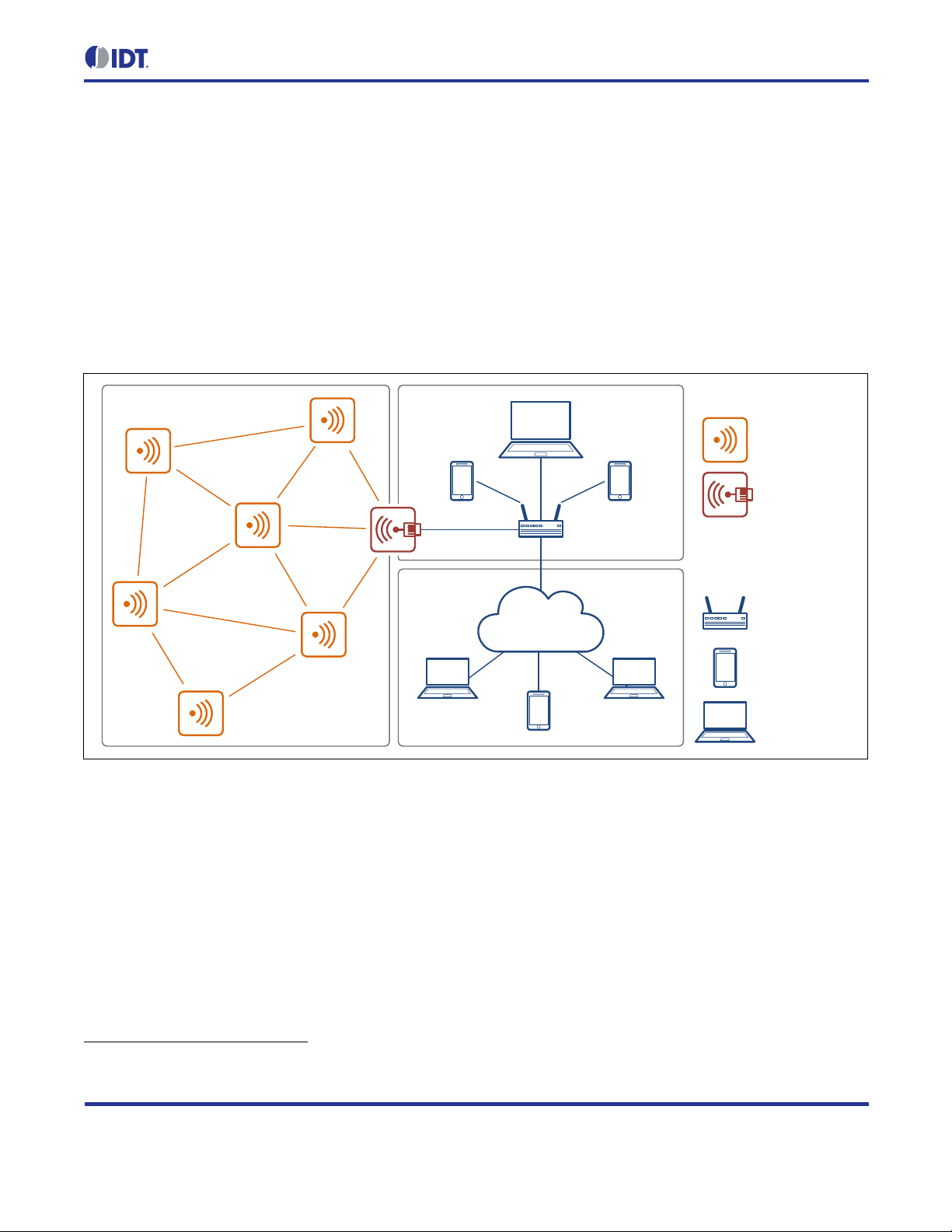
1 Introduction
This guide describes the u sage of the 6LoWPAN app lication programming interface ( API) for application development using ZWIR451x modules. These modules provide bidirectional IPv6 communication over an IEEE
802.15.4 wireless n etwork. Using IPv6 as the ne twork layer protocol allows easy integration of sensor or actor
nodes into an existing Int ernet Protocol (IP) infrastructure with out the need for additional hard ware. Refer to the
data sheet for the ZWIR451x module for detailed information about the module, including pin assignments.
Figure 1.1 ZWIR451x Application Domain
Figure 1.1 shows a t ypical network conf iguration. The Personal Are a Network (PAN) is built from a set of various
ZWIR451x m odules. T he network is c onnected via a border router to the local are a net work (LAN) and from there
to a wide area network (WAN) such as the Internet. With this setup, each module can be accessed from
anywhere in the world with just its unique IPv6 address.
The radio nodes are t ypically organized in a m esh topology. Routing of IP packets over this topology is handled
by the software stack tr ansparently for the user. T he network allows dr opping in new nodes or removing existing
nodes without requiring manual reconfiguration. Routes to new nodes will be found automatically by the stack.
Application software runs on an STM32F103RC ARM® Cortex™ M3
ZWIR451x API. The MCU is clocked with up to 64 MHz and provides 256 kB yte flash memory and 48 kByte RAM,
which allows the implementation of memory and computationally intensive applications. The API provides
functions to communicate with remote devices, access different I/O interfaces, and support power-saving modes.
* The ARM® and Cortex™ trademarks are owned by ARM, Ltd.
*
microcontroller (MCU) on top of the
Page 6

ZWIR451x Programming Guide
© 2016 Integrated Device Technology, Inc. 6 April 12, 2016
1.1. IPv6
IPv6 is the successor of the IPv4 protocol, which has been the major network protocol used for Internet
communication over the p ast decades. One of the main advantag es of IPv6 over IPv4 is its huge addres s area,
which provides 2
128
(about 3.4 x 1 038) unique address es. This enormous addres s space allows assignm ent of a
globally unique IP address to every imaginable device that c o uld be connected to the Internet. Another a dv an tage
with respect to sensor network s is the stateless address auto-configur ation m echanism, allow ing nodes to obtain
a unique local or global IP address without requiring a specific server or manual configuration.
The use of IPv6 makes it possible t o connect sensor networks directly to the In ternet. Basically this is possible
with other network protocols, too, but thos e require a dedicated gateway that translates n etwork addresses to IP
addresses and vice versa. Usually this translation requires application knowledge and maintenance of the
application state in the b order router, and therefore changing the border rout er software might be required with
each application update. The protocol gateway might also introduce an additional point of attack if secure
communication between devices inside and outside of the PAN is required.
IDT’s 6LoWPAN implem entation supports IPSec, which is the m andated standard for secur e communicatio n over
IPv6. The use of IPv6 throughout the whole network allows real end-to-end security.
1.2. 6LoWPAN
IPv6 has been designed for high bandwidth internet infras tructure, which does not put significant co nstraints on
the underlying net work protocols due to the vas t amount of mem ory, computing power, and energy. In contras t,
the IEEE 802.15.4 stand ard is intended f or lo w data-r ate com m unication of de vices with ver y lim ited availability of
all these resources. In order to make both standards work together, the 6LoWPAN standard (RFC 4944) has
been developed by the Internet Engineering Task Force (IETF) to carry IP packets over IEEE 802.15.4 networks.
6LoWPAN adds an adaptio n layer betw een the link layer and network layer of the Open Systems Interc onnection
(OSI) reference model. This layer performs compression of IPv6 and higher layer headers as well as
fragmentation to get large IPv6 packets transmitted over IEEE 802.15.4 networks. The 6LoWPAN layer is
transparent for the us er, and therefor e on 6LoW PAN devices, the IPv6 pro tocol is used i n exactly the sam e way
as on native IPv6 dev ices. The presence of the 6LoWPAN adaption la yer does not restrict IP function ality. The
user of a 6LoWPAN system does not recognize the existence of the 6LoWPAN layer.
1.3. Organization of this Document
Sections 2 to 7 cover the A PI documentatio n, which is divided into two parts. T he first part, c overed b y section 2
provides a functional descr iption of t he network s tack. It explains the cor relation of the different API func tions and
provides background information about s tack internals . The second par t is the function ref erence and is co vered
by sections 3 to 7. If familiar with the general stack functionality, the reader can simply use these sections to look
up function signatures or basic usage information.
Section 8 explains how user applications can use the resources provided by the microcontroller and which
resources are blocked by the operating system.
Terms set in bold monospace font can be clicked, activating a hyperlink to the section where a detailed
definition of this term can be found.
Page 7

ZWIR451x Programming Guide
© 2016 Integrated Device Technology, Inc. 7 April 12, 2016
2 Functional Description
The following subsecti ons give a generic overview of the different func tionalities of the firmware delivered with
ZWIR451x modules. Background information is provided if required for proper use of the libraries. Usage
recommendations are gi ve n f or optimal performance in cert ain app lic at ion configurations. A de tai le d des cr ip tion of
the functions, types, and variables available for application programming is given in sections 3 through 7.
2.1. Requirements Notation
This document uses s everal words to i ndicate the requirements of IDT’s 6LoWPAN stack implem entation. The
key words M
O
PTIONAL, set in italic small caps letters denote requirements as described below
M
UST, SHALL, REQUIRED These words denote an a bsolute requirem ent of the im plem entation. Disregardi ng these
requirements will cause erroneous function of the system.
M
UST NOT, SHALL NOT These phrases mean that something is absolutely prohibited by the implementation.
Disregarding these requirements will cause erroneous function of the system.
S
HOULD, RECOMMENDED These words descr ibe best practice, b ut there might be reasons to disregard it. Before
ignoring this, the implications of ignoring the recommendation must be fully understood.
UST, MUST NOT, REQUIRED, SHALL, SHALL NOT, SHOULD, SHOULD NOT, RECOMMENDED, MAY and
S
HOULD NOT, NOT RECOMMENDED These words describe items that can impair proper behavior of the system
when implemented. H owever, there might be reasons to ch oose to implement the item anyway. Implications of
doing so must be fully understood.
M
AY, OPTIONAL T hese words describe items which ar e optional. No misbehavior is to be expected when these
items are ignored.
2.2. Terms
This document distingu ishes between t hree types of functions: h ooks, callbacks , and API functions. Basically, all
three types are def ined as normal f unctions in the pro gramming language C, b ut they differ in the way that they
are used.
API Functions are functions which are defined and implemented by IDT’s 6LoWPAN stack. They provide a
functionality that can be ac cessed b y the user code. T he declarations of API func tions are provi ded in the he ader
file belonging to the library in which the function is implemented.
Hooks are functions that provide the user the abil ity to extend the default behavi or of the stack . They are called
from the operating system (OS) to give the application the op portunity to im plement custom features or reactions
to events. The oper ating s ystem provides a defau lt implem entation of the h ook that is cal led if no c ustom hook is
defined. The protot ypes of all available h ooks are defined in the header file b elonging to the libr ary in which the
default implementation is loc ated. ZWIR_AppInitNetwork and ZWIR_Error are examples of hooks.
Callbacks are also called from the operating system, but they must be registered explicitly at the OS. The
function may have a custom name, but the signature m ust be matching. Cal lback functions are register ed at the
OS using API functions. O ne example for a function expecting a cal lback is ZWIR_OpenSocket. In contrast to
hooks, callbacks do not have default implementations. For each callback function, there is a type declaration
declaring how the signature of the user function should look.
Page 8

ZWIR451x Programming Guide
© 2016 Integrated Device Technology, Inc. 8 April 12, 2016
variableName, functionArgument
FunctionName
TypeName_t
PREPROCESSOR_MACRO
2.3. Naming Conventions
For better readability of the code, all user accessible func tions and types of the API comply with a set of nam ing
conventions. Each identif ier that is an element of the API is prefixed with “ZWIR_.” Function, variable, function
argument and type identifiers are defined using “CamelCase” style. This means that each single word of a
multiple word identifier star ts with a capit al letter. The rem aining letters of the wor d are lower case. Prepr ocessor
macros are defined using all capital letters.
Different style rules apply to func tions, variables , and types definitions . Function-name and type-name identifiers
start with a capital le tter in the first word, while variab le identifiers start with a l ower case letter in the first wor d.
Type names have an add itional “_t” suffix. Varia ble names and function ar guments are not diff erentiated in the
naming conventions.
Table 2.1 Naming Conventions Used in C-Code
Identifier Type Style
First word starts with lower case, all other words with capital letters.
All words start with capital letters (“CamelCase”).
All words start with capital letters and name ends with “_t” s uffix.
All letters are capitalized.
2.4. Library Architecture
ZWIR451x modules are f reely programmable by means of an API that is im plemented in a set of libraries. The
libraries provide different functionality and can be linked into the user program. The use of the core library is
mandatory, as it pro vides t he operat ing s ystem and a ll gener ic comm unication functional ity. All other l ibraries are
optional and can be link ed depending on the requ irements of the target ap plicatio n. Each libr ary exposes a set of
functions and types that are required to im plem ent the desired func tionalit y. The librar y architectur e is depic ted in
Figure 2.1.
To make programm ing as easy as poss ible, t he librari es m ake use of an event and c omm and approac h wher ever
possible. Using th is approa ch, applic ation code is not required t o poll f or data o n the dif ferent inter faces. Ins tead,
newl y available data is pas sed to user-defined callback functions automatically. Timer hooks and callbacks are
available, and they are automatically executed periodically or after expiration of a user-defined time interval.
Linking the library without any additional code will result in a valid binary that can be programmed on a radio
module. Such binaries will not provide user-specific functionality. However, the nodes relay packets in mesh
networks and respond to ping requests . In order to add functionality, several functions that have empty default
implementations can be defined by the user.
Page 9
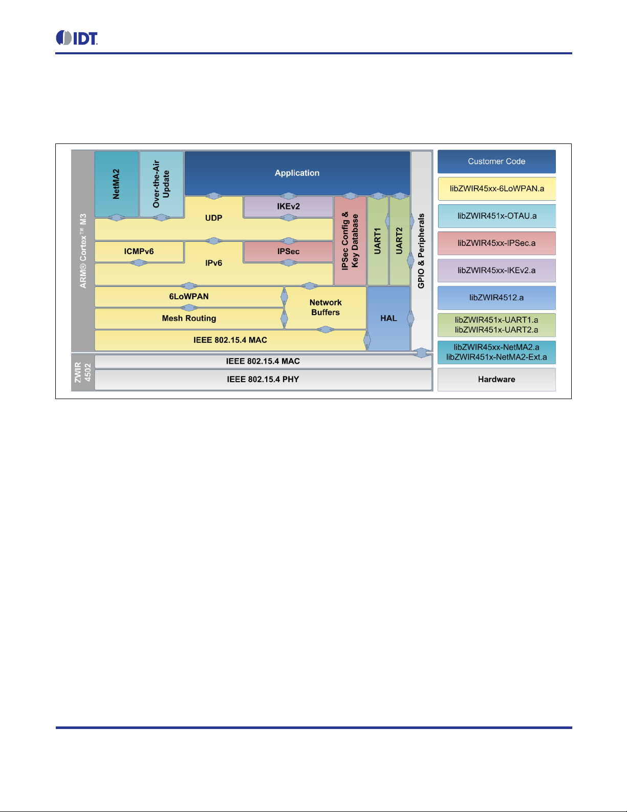
ZWIR451x Programming Guide
© 2016 Integrated Device Technology, Inc. 9 April 12, 2016
Figure 2.1 Library Architecture
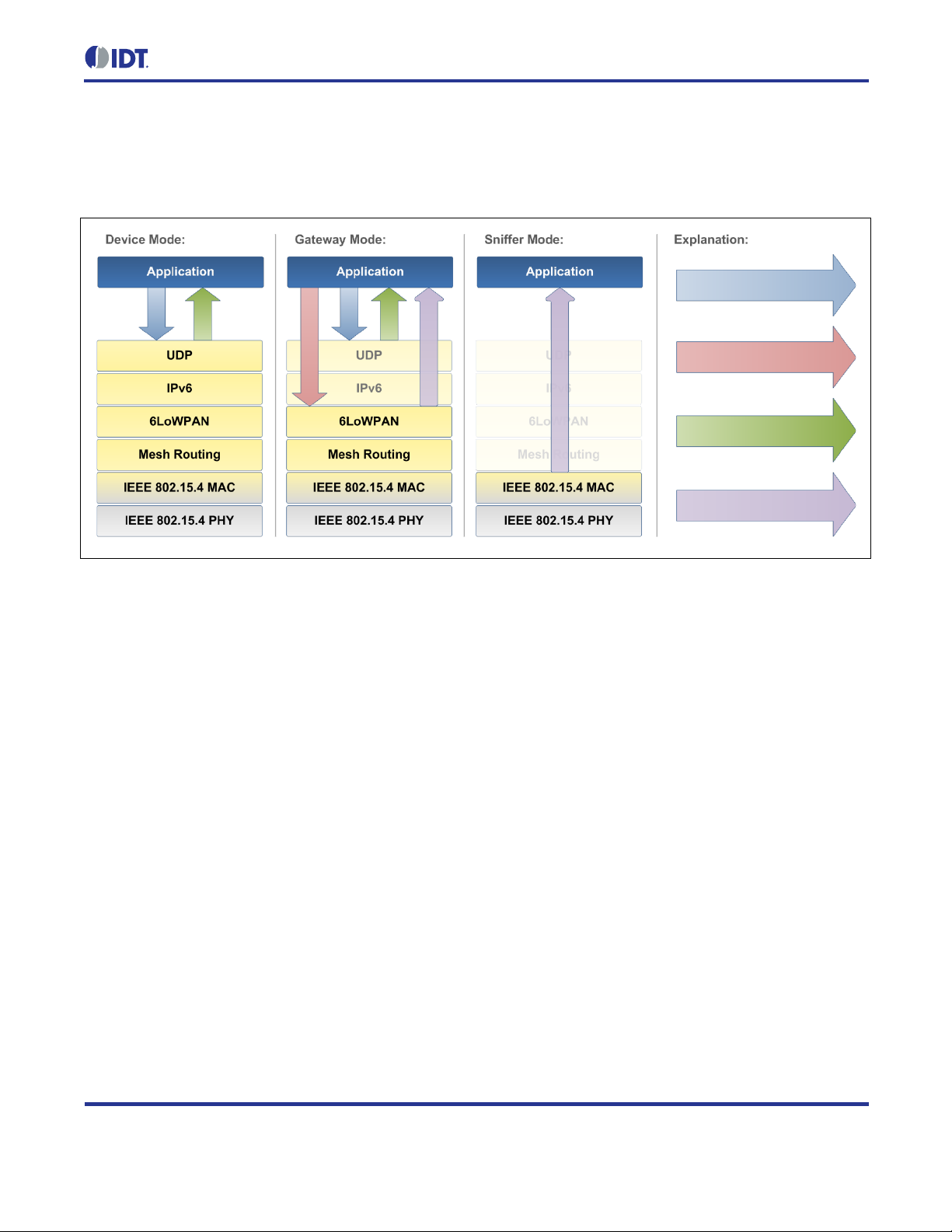
2.5. Operating Modes
The API provides thr ee operating modes: Devic e Mode, Gateway Mode and S niffer Mode. The modes di ffer in
how many of the protocol layers are pr oces s ed b y the net work s tack. All other API functionalit y rem ains the s ame.
Setting the operatin g m ode of a n ode must be done b efore an y ini tiali zation of th e API and th e hard ware. F or th is
purpose, the ZWIR_SetOperatingMode function is provided. Figure 2.2 shows how applicat ion code interfac es
into the network stack in diff erent operating modes. A description of the three different modes is provided i n the
next subsections.
2.5.1. Device Mode
The Device Mode is preconf igured since this is the most commonly used mode for ZWIR451x modules. Each
node with sensing or acti ng f unc tiona lity should use this operati ng mode. Full protocol proces s ing is p er f orm ed for
incoming and outgoing data. This means that all header inform ation is removed from incoming Us er Datagram
Protocol (UDP) pac kets and onl y payload dat a is passed to the applicat ion. Accor dingly, the ap plication on ly has
to provide payload da ta tha t should be s ent ov er the net work. T he stack automaticall y adds all necess ary header
information.
Device-configured devices behave as normal IPv6 devices. Theref ore address auto-configura tion and neighbordiscovery is performed as defined by the IPv6 standard. Data are sent and received over UDP sockets. The
functions ZWIR_SendUDP and ZWIR_SendUDP2 serve as an interface to the network stack. Incoming data is
passed to an application callback that must be registered when a socket is opened using ZWIR_OpenSocket.
Page 10
ZWIR451x Programming Guide
© 2016 Integrated Device Technology, Inc.
10
April 12, 2016
ZWIR_SendUDP(2)
ZWIR_Send6LoWPAN
ZWIR_OpenSocket
ZWIR_SetOperatingMode
Figure 2.2 Application Interface into the Protocol Stack in Different Operating Modes
2.5.2. Gateway Mode
The Gateway Mode is i ntended for use with modules that should work as protocol gate ways. Protocol gat eways
change the physical media used for IPv6 pack et tr ans mission. This enables the i ntegration of 6LoWPAN networ ks
into Ethernet-based IPv6 networks for example.
In contrast to the Device Mode, not all ne twork layers are pr ocessed in Gateway Mode . For any IPv6 pack et that
is received via the air interface, o nly the 6LoWPAN-s pec ific m odif icatio ns of the h eader s are r emoved, resulting in
a packet containing all IPv6 and higher layer headers. This packet is passed to the receive callback function.
Accordingly, all data that need to be sent over the network are assumed to have valid IPv6 and higher layer
headers. Only 6LoWPAN-specific modifications will be applied to outgoing packets.
Gateway-configured device s do n ot per form addres s auto-configuration and neighbor-disc over y as d efined b y the
IPv6 standard. Moreover no router solicitation and router advertisement messages are generated automatically.
To enter the Gatewa y Mode, ZWIR_SetOperatingMode must be called from ZWIR_AppInitHardware. It is
not possible to call ZWIR_SetOperatingMode from any other loc ation in the cod e. ZWIR_SetOperatingMode
accepts a callback f unction that is called u pon reception of data in the gat eway. Sending data is accom plished
using the function ZWIR_Send6LoWPAN.
2.5.3. Sniffer Mode
The Sniffer Mode is provided to al low observation of raw network traff ic. No protocol processing is perform ed.
Thus the data passed to the application layer includes all header information. In contrast to the two other
operating modes, all packets received over the air interface are passed to the application, regardless of the
address to which the packet has been sent. This also includes MAC layer packets.
Page 11

ZWIR451x Programming Guide
© 2016 Integrated Device Technology, Inc.
11
April 12, 2016
Sniffer Mode is useful for debugging purposes. It can be used to find out which devices in the network are
transferring packets and which are not. Sniffer Mode devices do not generate any network traffic—not
autonomously or user trig gered. That is why there is onl y an interfac e from the s tack to the app lication co de, but
not vice versa.
To enter Sniffer Mode , call ZWIR_SetOperatingMode ( ZWIR_omSniffer, YourCallbackFunction ) f rom
ZWIR_AppInitHardware. The functions ZWIR_Send6LoWPAN, ZWIR_SendUDP and ZWIR_SendUDP2 do not
function in this mode. However, it is sti ll possible to chang e the physical chan nel and the modulati on scheme of
the transceiver by calling ZWIR_SetChannel and ZWIR_SetModulation.
2.6. Operating System
The operating system is ve r y light-wei ght and does not pro vide m ulti-threading. This means that any user-defined
function that is called from the operating system is completely executed before control is passed back to the
operating system. Therefore, the user is re quired to write cooper ative code. User s must be aware that f unctions
requiring long execution t ime will bloc k the operating system kernel and m ight cause the kernel to m iss incoming
data, regardless of whet her they are received over the air or any wired interface.
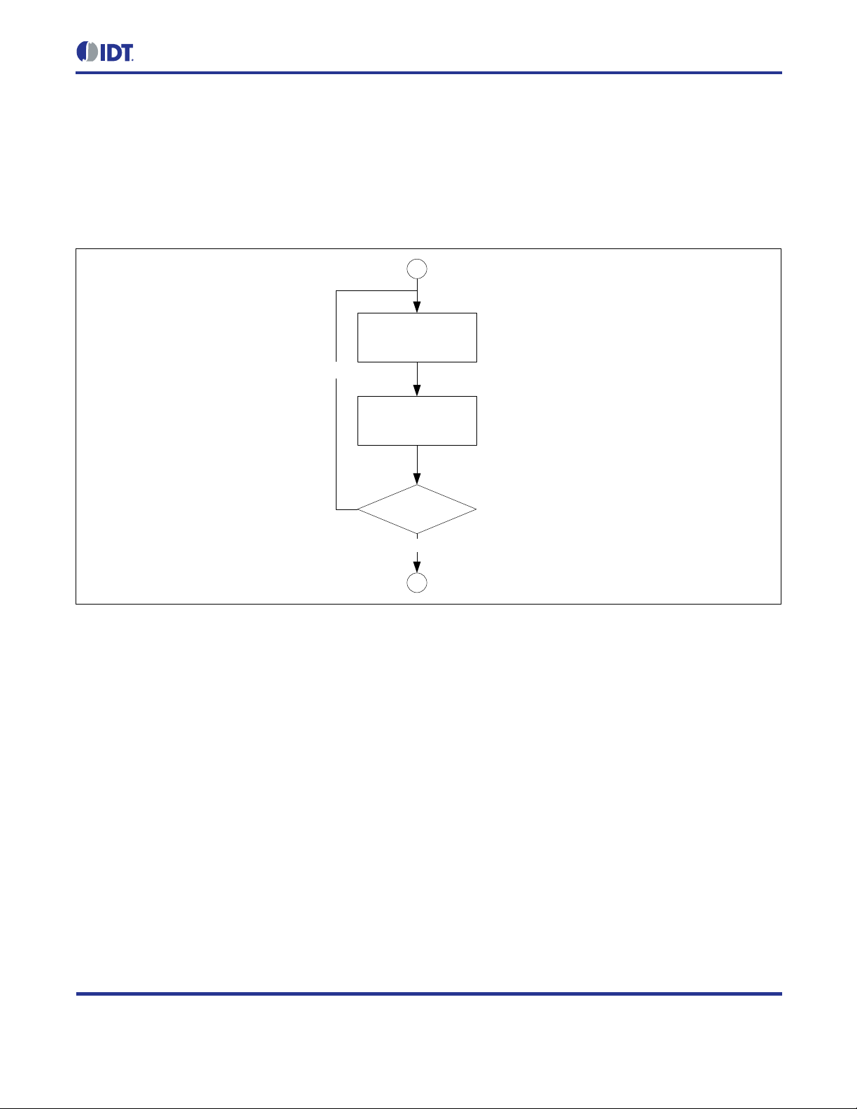
2.6.1. Initialization
During the operating system initialization phase, the different libraries and the MCU peripherals required for
system operation are initialized. Startup initialization is done in two phases, each with its own hook for user
application code. During the firs t phase, the internal clocks and the periphera ls used by the stack are initialized
and the random number generator is seeded. Also peripherals requ ired by certain libraries are initia lized if the
corresponding librar y is link ed int o the proj ect. Af ter thi s, the ZWIR_AppInitHardware hook is call ed if present,
enabling application code to initialize any additional hardware. The application can initialize its I/Os and
peripherals in this function. ZWIR_SetOperatingMode must be called from here if the Gateway Mode is
required. Sending data ov er the network or initiali zing network sock ets is not possible from here, as the network
stack is not in itialized. However, func tions controlling t he physical parameters of the network (e.g. , output power
or physical channel)
SHOULD be called from here.
During the second phase, the transceiver and the net work stack are initialized. If the Norm al Mode is selected,
duplicate address detec tion (DAD) is also started and r outer information is solicited. DAD chec ks if the address
given to the m odule is uni que on t he link . After finishing network init ializa tion, ZWIR_AppInitNetwork is called.
Application code can do its r emaining initializati on tasks such as setting up sockets at this po int. Since DAD and
router solicitation are started before the call to ZWIR_AppInitNetwork, it is recommended that physical
parameters of the network are set up first in ZWIR_AppInitHardware. This ensures that DAD and RS are
performed on the correct channel with correct settings.
2.6.2. Normal Operation
During normal operation, t he operating system collects events f rom the different peripherals an d the application
and handles them acc ording to their priorit y. Event pro cessing prior ities are f ixed and cann ot be change d. Events
are processed highest prior ity first; the lowest num ber represents the highest priority. Table 2.2 lists all even ts
with their priorities and triggered actions.
Page 12

ZWIR451x Programming Guide
© 2016 Integrated Device Technology, Inc.
12
April 12, 2016
ZWIR_Main10ms
ZWIR_Main100ms
ZWIR_Main1000ms
Table 2.2 Event Processing Priority in the Main Event Loop
Priority Event Triggered By Effect
0 Application Event 0 Application Code Call user-defined callback function
1 Transceiver Event Transceiver Interrupt Request Process transceiver request
2 Application Event 1 Application Code Call user-defined callback fun c tion
3 Callback Timer Expired SysTick Controlled Software Timer Call user-defined cal lba ck fun c tion
4 Sleep Requested Software Sleep for the requested time
5 Received Data on UART1 UART1 Interrupt Call user-defined callback fun c tion
6 Application Event 2 Application Code Call user-defined callback function
7 10ms Timer Expired SysTick Controlled Software Timer
Call
8 100ms Timer Expired SysTick Controlled Software Timer
9 1000ms Timer Expired SysTick Controlled Software Timer
10 Application Event 3 Application Code Call user-defined callback fun c tion
11 Received Data on UART2 UART2 Interrupt Call user-defined callback function
12 Sending Data Failed due to
Resource Conflict
13 Application Event 4 Application Code Call user-defined callback func tion
Network Stack Retry sending
Call
Call
The operating system provides five application eve nt handlers that can be used to process applicat ion events in
the context of the operating system scheduler. Application event handlers
SHOULD be used to react to
asynchronous events requiring computationally intensive processing. Interrupts are a typical example for such
events. If an interrupt occurs, the int errupt servic e routine (ISR) c an trigger an e vent and de lay the process ing to
an appropriate time. This ensures that multiple asynchronous events are handled in the order of their priority,
without blocking interrupts.
Application events are triggered by calling ZWIR_TriggerAppEvent with the corresponding event number
(0 through 4). When the OS scheduler reaches the user-triggered event, an application callback function is
executed. Multiple cal ls to this function before the cor responding application callback is invok ed will not cause
multiple invocations of the application callback.
For each application event, an event handler callback function must be registered using
ZWIR_RegisterAppEventHandler. If no event handler is registered f or a certain event, triggering this event
has no effect. In order to change an ev ent handler, ZWIR_RegisterAppEventHandler must be called agai n
with the new handler. Unregistering event hand lers can be performed by calling the r egistration function with a
NULL callback argument.
Page 13

ZWIR451x Programming Guide
© 2016 Integrated Device Technology, Inc.
13
April 12, 2016
2.6.3. Power Modes
The stack support s different modes to r educe the power c onsumption of the de vice. In Active Mode, all module
features are available. The Sleep, Stop, and Standby Modes reduc e the power consum pt ion by disabli ng dif fer ent
module functionalit ies. Eac h of the power-saving modes affec ts the behav ior of the M CU and t he transc eiver and
supports different wake-up conditions.
Table 2.3 Power Modes Overview
Mode Wakeup Clock Context1) I/O Transceiver
Source Time MCU Core Peripherals
Active On On 2) Retained As configured On 3)
Sleep Any IRQ 1.8 µs Off On 2) Retained As configured Off 4)
Stop
Standby
1)
Refers to the status of the RAM and peripheral register contents after wakeup – the backup registers of the MCU are always
2)
Clock is enabled for all peripherals that have been enabled by application code and all peripherals that are used by the library.
3)
Can be powered off by application code.
4)
Remains on if peripheral/transc eiver is sel ect ed as wakeup source.
RTC IRQ
External IRQ
RTC IRQ
Wakeup P in
available.
5.4 µs Off Off Retained As configured Off
50 µs Off Off Lost Analog input Off
4)
Active Mode is entered autom atically after startup. In this mode, the MCU core and all p eripherals used by the
application are run ning and all functionality is a vailable. The transceiver is t ypically on but can be switched off
explicitly by a call to ZWIR_TransceiverOff. This mode has the highest power consumption.
In Sleep Mode, the MCU core is disa bled bu t the MC U perip hera ls are stil l functioning if required. The trans c eiver
can be switched on or off. Mem ory contents and I/O s ettings remain in the stat e that was active at the activa tion
of the Sleep Mode. Waking up from Sleep Mode is possible on an y MCU interrupt. After the wakeup event, the
stack continues executio n at the position it had been s topped. The power consu mption in Sleep Mode is slightl y
reduced compared to Active Mode. If more signific an t r eductio n of the power consumption is required, the Stop or
Standby Modes should be considered.
Stop Mode provides significant reduction of power consumption while still providing a short wakeup time and
context saving. Dependi ng on the application’s requirements , the transceiver could rem ain enabled to wake up
the module when a packet comes in (set the trans ceiver as the wak eup source). By default, the tra nsceiver is
disabled in Stop-Mode. The MCU core and al l periph er als of the MC U are dis able d in Stop Mode. Wakeup is onl y
possible by the built-in real-time clock (RTC) or an external interrupt, triggered at any GPIO l ine. For that, the
external interrupt must be configured appropriately.
Standby Mode is the lo wes t po wer mode. In this mode, the MCU is po were d of f and the tr ans ce iv er is on s tan db y.
Only the MCU’s internal RT C is running, serving as a wakeup source. Additionall y, the external wakeup pin can
be used to wake up the module. Aft er wakeup, the memory contents of the MCU ar e l ost and must be rei nit i alize d
the same as after normal power-on.
Page 14

ZWIR451x Programming Guide
© 2016 Integrated Device Technology, Inc.
14
April 12, 2016
Any of the low power modes is entered by calling the function ZWIR_PowerDown. It can be chosen whether
power-down is delayed until all pending events are processed or not. If delayed power down is chosen, the
power-down procedure can be aborted by a call to ZWIR_AbortPowerDown. The wakeup sources for the
different power modes are configured by ZWIR_SetWakeupSource.
2.6.4. Error Handling
The stack performs error handling in two dif ferent ways. The firs t is simply to reset the ch ip if an unrecoverable
MCU exception occurs that caused an interrupt. For errors that ar e not caused by MCU exceptions, the stack
provides a default handling, which may be overwritten by the application code.
The error handlers perfor ming a system reset are trigg ered by one of the interrupts listed i n Table 2.4. The reason
for resetting the whol e system is that in the case of no rmal operat ion, none of the liste d interrupts s hould ap pear.
However, if different beh avior is desired, it is possible to overwrite the d efault implementation by providing the
user’s own interrupt service routines. See section 10.3 for details.
Table 2.4 Interrupts that Result in a System Reset
Resetting Interrupts
Non-maskable Interrupt
Hard Fault
Memory Management
Bus Fault
Usage Fault
Programmable Voltage Detector
In the case of a r ecoverable error , the ZWIR_Error hook is called by the opera ting system . The error num ber is
passed as a function argument. In order to provide custom error handling, the application
MUST provide an
implementation of ZWIR_Error. T he return value of the func tion determ ines whether th e error has been handl ed
by the application (return true) or if the default handler will be executed (return false).
2.7. Firmware Version Information
The ZWIR451x API provide s the capability of includin g firm ware version inf ormation in the s tack. This information
can be requested remotel y af ter wards an d is required by the F irmware Over-the-Air Update Library. The complete
firmware version cons ists of the Vendor ID, the Firm ware ID, the Major Firmware Versi on, the Minor Firmware
Version, and the Firmware Version Ex te ns io n. T hes e c omponents are defined in t he ap plication code using g lob al
variables. The role of the different components is explained in the following subsections.
In addition to t he firm ware versio n inf ormation m entio ned abo ve, the s tack provides addit ional ver sion i nformation
for the library t o whic h the application was link ed. This vers ion inform ation consist s of Major Stack Version, Min or
Stack Version, and Stack Version Extension field.
Page 15

ZWIR451x Programming Guide
© 2016 Integrated Device Technology, Inc.
15
April 12, 2016
2.7.1. Vendor ID
The Vendor ID is a 32-bit num ber that identifies the c ompany that developed the device firm ware. A Vendor ID
must be requested from IDT. Each company must obtain its own Vendor ID before placing products on the
market. The Vendor ID is set using the global varia ble ZWIR_vendorID. If this variable is not set, the firmware
will use the Vendor ID E966
firmware.
, which is reserved for ex perim ental purpos es and mus t not be used f or production
HEX
2.7.2. Product ID
The Product ID is a 16-bit num ber identifying the pro duct firmware. It is espec ially important for the Ov er-the-Air
Update functionality but could also serve for remote identification of the device type. Refer to the ZWIR451x
Application Note – Enabling Firmwar e Over -the-Air U pdates for more inf ormation about th e role of the Produc t ID
in IDT’s Over-the-Air Update Library.
The Product ID is set by defining the global variable ZWIR_productID. If this variable is not def ined, the value
will be read as zero.
2.7.3. Major Firmware Version
The Major Firmware Vers io n is a version inform ation f i el d that is freely us ab le f or app lic at ion pur pos es . It is s et by
defining the global vari able ZWIR_firmwareMajorVersion. If this variab le is no t def ined, the value will be read
as zero.
2.7.4. Minor Firmware Version
The Minor Firm ware Ver sio n is a vers ion i nf ormation field that is freely usable f or application purposes. It is set by
defining the global vari able ZWIR_firmwareMinorVersion. If this variab le is no t def ined, the value will be read
as zero.
2.7.5. Firmware Version Extension
The Firmware Version Ext ension is a version information fie ld that is freely usable for application purposes. It is
set by defining the glo bal var iable ZWIR_firmwareVersionExtension. I f this vari able is n ot d efined, the value
will be read as zero.
2.7.6. Library Version
IDT’s firmware stack libraries have their own vers ion information included. This inf ormation is compiled into the
binary libraries and can be requested by the application c ode using the function ZWIR_GetRevision. Like the
firmware version, the library version consists of the major and minor versions as well as extension information.
2.8. Addressing
Each module has t hree types of addresses : a PAN id entifier, link layer address, and network layer address. This
section describes the different address types and explains how they are used in the stack.
Page 16

ZWIR451x Programming Guide
© 2016 Integrated Device Technology, Inc.
16
April 12, 2016
2.8.1. Address Types
The PAN identifier (PANId) is a 16-bit-wide number carrying an identifier of the network. Each device in the
same network must have the same PANId. Nodes wit h differ ent PANIds cannot comm unicate. A defau lt PANId is
preprogrammed in the network stack. The current PANId can be requested or changed using the functions
ZWIR_GetPANId and ZWIR_SetPANId, respectively. The default value is ACCA
The link la yer address is also ref erred to as the M AC address or P AN address. This addres s is used by the
lower communication la yers and does not need to be handled directl y b y the user. The link layer addr ess must be
unique in the network . Each ZWIR451x module has a predefined, hardw are program med address that is globally
unique. The PAN address is 64-bits-wide. It can be requested and changed by the functions
ZWIR_GetPANAddress and ZWIR_SetPANAddress. Changing the PAN address is not recommended as thi s
could cause problems as described in section 2.8.4.
The third address t ype is the net wo rk layer add ress, which is equiv alent t o the I Pv6 Addres s. T hese addr esses
are 128-bit-wide. They are us ed by the applicat ion to determ ine the destin ation that pack ets should be sen t to or
the source packets should be received from. Each device needs at least one IPv6 address to be reachable.
However, multiple a ddresses can be ass igned to each no de. IPv6 ad dresses assigned to a node m ust be unique
on the network. However, typically users do not need to handle IPv6 address assignment. IPv6 provides a
mechanism that performs automatic address configuration. This mechanism is explained in section 2.8.3.
HEX
.
2.8.2. IPv6 Addresses
IPv6 addresses are 128-bit and therefore 16-bytes wide. As it woul d be impractical to us e the byte-wise notation
known from IPv4, IP v6 introduces a new nota tion. IPv6 addr esses are represented b y eight 16-bit hexadecim al
segments that are separated by colons. An example for such address is
2001:0db8:0000:0000:1b00:0000:0ae8:52f1
The leading zeros of segm ents can be omitted as they do not car ry information. Furthermore the IPv6 not ation
allows om itting a sequence of zero segment s and representing it as double c olon. With these rules, the above
address can be written as
2001:db8::1b00:0:ae8:52f1 or 2001:db8:0:0:1b00::ae8:52f1
However, replacing multiple zero segments is not allowed, so the following address is invalid:
2001:db8::1b00::ae8:52f1
An IPv6 addres s consist s of two components: a prefix and an int erface iden tifier. T he prefix s pecifies the network
that a device is part of; the interface ide ntifier specifies the interf ace of a device. A node with multiple ne twork
interfaces has multip le interface identifiers. The si ze of the prefix varies f or different address types. In the IPv 6
address notation, t he prefix length can be appe nded t o the addres s w ith a slas h f ollowed b y the num ber of pr efix
bits. For example, th e notation 2001:db8::/64 re presents a network c ontaining the addresses from 2001:db8:: to
2001:db8::ffff:ffff:ffff:ffff.
IPv6 supports three kinds of addressing methodologies: unicast addres sing, multicast addressing, and anycast
addressing. Unicast and multicast addresses differ in how the pref ix is formed. Anycast addres s es can be used as
target addresses and are handled like unicast addresses.
Page 17

ZWIR451x Programming Guide
© 2016 Integrated Device Technology, Inc.
17
April 12, 2016
Prefix
Interface-Identifier
127 64 63 0
Prefix
Multicast Group ID
127
111 0
0xff
8
Scope
Flags
4
4
Unicast addresses are s hown in Figure 2.3 and use 64 bits each f or the pref ix a nd the inter face ide ntifier. Unicas t
addresses exactly ide ntify one single interface in a net wor k . T he prefix of the address determines the s cope of the
unicast address. If the pr efix equals fe80::/64 this is a link-local unicas t address. Link local addresses are valid
only on the single link a node is c onnec te d to. The prefix of global unicast addr es ses is rec eived via ad dres s autoconfiguration from a r outer that is conn ected to the Int ernet. Ther e are addition al prefix configuratio ns with lim ited
scope that are not covered by this documentation.
Figure 2.3 IPv6 Unicast Address Layout
Multicast addressing allows sending out a single packet to multiple receivers. For this purpose, IPv6 provides
multicast addresses. A multicast address can only be used as the destination address, never as the source
address of a pack et. The la yout of a m ulticast addres s is shown in Figure 2.4. Multicast a ddresses h ave a 16-bit
prefix with the most significant 8 bits set to FF
, followed by two 4-bit fields for flags and the scope of the
HEX
multicast packet. The remaining bits specify the multicast group ID.
Figure 2.4 IPv6 Multicast Address Layout
In this document, it is assumed that the f lags field is a lways either 0000
multicast address is a wel l-known address . 0001
m arks the address as a tem porarily assigned ad dress that is
BIN
or 0001
BIN
BIN
. 0000
specifies that the
BIN
not specified by Internet s tandards. These addr esses must be used for custom multicast addres sing. The scope
field is always assum ed to be 0010
, representing the link-local scope. Other scopes are us able but must be
BIN
supported by routers.
Two specific addresses shoul d be noted as these are used very often. M ore information about their us e can be
found in section 2.9.2.
1. The unspecified address ::
All segments of this address are zero. It is used by receivers to listen to any sender. This address must
never be used as destination address.
2. The link-local all nodes multicast address ff02::1
Packets sent to this address are received by all nodes in the network, so this multicast address is
equivalent to broadcasting.
For more detailed information about IPv6 addressing refer to RFC 4291
– “IP Version 6 Addressing Architecture.”
Page 18

ZWIR451x Programming Guide
© 2016 Integrated Device Technology, Inc.
18
April 12, 2016
2.8.3. IPv6 Address Auto-configuration
IPv6 provides a stateless address auto-configuration mechanism. This mechanism allows the configuration of
node addresses from information that is statically available on the node and information provided by routers.
Router information is only require d if global communication is required . Addresses for link-local comm unication
can be derived from the link-layer address. This removes the need for manual configuration of addresses or
dynamic host configuration protocol (DHCP) servers in the network.
The local information used f or auto-configuration is the interf ace EUI-64 address. T he EUI-64 address is a factor y
programmed link-layer address that IDT guarantees to be unique for each m odule. The EUI-64 address is often
referred to as the MAC address. During network initialization, each node generates a unique link-local IPv6
address by putting the pref ix fe80::/64 in f ront of the EUI -64 address with bit 1 of the most significant EUI -64 byte
inverted. Assuming a link -layer address of 00:11:7d:00:12:34:56:78, the gen erated link-local IPv6 a ddress would
be fe80::211:7d00:1234:5678.
It is possible to switch off the link-local address generation by setting the stack parameter
ZWIR_spDoAddressAutoConfiguration to zero before the stack initialization.
In addition to link-local address generation, nodes request router information during startup seeking a global prefix
for building a glo ba ll y va lid addr es s. Those requests ar e cal le d r ou ter s o lici tat ions . Routers present on t he link will
respond to router solicitation messages of the node with router advertisements containing global prefix
information. Taking this prefix and the EUI-64 address of the node, a global address is generated in the same way
as for the link-local address. Router solicitation is done automatically during the startup phase.
If there is no router o n the link, no global address will be ass igned and onl y link -local communicatio n is poss ible.
In this case, the router solicitation messages can be suppressed by setting the stack parameter
ZWIR_spDoRouterSolicitation to zero.
A host cannot rely on a generated address being unique, as there might be manually configured EUI-64
addresses on its link . Therefore, it must perf orm “duplicated address detec tion” (DAD) to be sure the gener ated
address is unique. Duplica te address detection is mandatory for each ad dress being attached to a node and is
performed automatic ally b y the networ k s tack. It is des cribed i n m ore detail i n the f ollowing sec tion. Each ad dress
being assigned to an interf ace is subject to duplicat e address detection. Addresses are not vali d until duplicate
address detection (DAD) is completed. Devices are not ab le to send or receive pac kets using a unicast ad dress
that has not been v alidated to be unique. After devic e startup (and therefore after assignm ent of the link-local
unicast address), the net work s tack calls the hook ZWIR_AppInitNetworkDone, s igna ling that D AD on th e link local address has been c ompleted and the addres s can be used. Applicati ons should use this hook to send out
initial packets.
2.8.4. Validation of Address Uniqueness
After a node has configur ed its own addr ess , it per forms Duplicate Address Detection (DAD) to check if the ne wly
configured IPv6 address is unique on the link . For this purpose, the no de starts to s end neighbor s olicitation (NS)
messages to the address to be checked (to its own address). If another node rep l ies to one of those messages or
if another node also se nds neighbor solicitation m essages to this address, the assigne d address is not unique
and must not be used. In this case, the error handler hook ZWIR_Error is called with the error code
ZWIR_eDADFailed. It is up to users to provide their own error handling mechanism for such cases.
Page 19
ZWIR451x Programming Guide
© 2016 Integrated Device Technology, Inc.
19
April 12, 2016
Assign
link-
address
Perform network
initialization
& DAD
DAD failed?
yes
no
Start
Normal Operation
The default implem entatio n prov ide d in t he library only r em oves t he f ai ling ad dr ess from the interface. If the failing
address was the only address of the module, the module will not be reachable.
Figure 2.5 Resolving Address Conflicts in L o cal Networks
Application code ca n try to resolve the address conflict. One possible solution is t o manually change the l ink-layer
address of the node, using random numbers or a dedicate d algorithm. ZWIR_SetPANAddress m ust be called
with the new address and the network initialization must be restarted. This is done by calling
ZWIR_ResetNetwork. The procedure can b e repeat ed f or an arbit rar y number of tim es until a un ique a ddr ess is
found.
Note that a duplicate address problem should not appear if each module in the network uses the factory
programmed link-layer address. In this case, the link-layer address is guaranteed to be globally unique.
Therefore, using the user’s own addresses is not recommended. For some applications, the user knows that there
are no duplicate a ddresses in the network. In such cases, the duplicate address detection mechanism can be
disabled by setting the stack parameter ZWIR_spDoDuplicateAddressDetection to zero. This has the
positive side effec t of the immediate abilit y to send and receive pack ets using the user’s own IPv6 address(es ).
Furthermore, less traffic is generated on the network.
Page 20

ZWIR451x Programming Guide
© 2016 Integrated Device Technology, Inc.
20
April 12, 2016
2.9. Data Transmission and Reception
Data are transmitted us ing the User Datagr am Protocol (U DP). If a destination node is not directl y reacha ble f rom
the source node, pack ets ar e routed ov er inter m ediate nodes autom atical ly. Rout e setup is done tr anspar entl y for
the user. The following subsections describe the different aspects of data transmission and reception.
2.9.1. User Datagram Protocol
The User Datagram Pr otocol is used for data communication. UDP is a connectionless and lightweight protocol
with the benefit of m inimal communication and pr ocessing overhead. No conn ection has to be created, and no
network traffic is required before data transmission between nodes can be started. Instead, communication is
possible immediately. However, UDP does not guarantee that packets that have been sent are reaching the
receiver. It is also possible that a single UDP p acket is rec eived multiple tim es. Furtherm ore, it is not guara nteed
that the receiving order of packets at the des ti nat io n is the s ame as the sending order at th e s ourc e. This must be
considered by the application programmer.
UDP uses the concept of ports to distinguish different data streams to a node. 65535 different ports can be
distinguished in UDP. A port can be seen as the address of a service running on a node. Depending on the
destination port of a pac ket, the network s tack dec ides to which service th e packet is routed on the receiver n ode.
In IDT’s 6LoWPAN stack, services that provide the callback f unctions to which network packets are passed are
running in the application code. Each service has its own callback function.
2.9.2. Data Transmission and Reception
Data transmission is requested by calling ZWIR_SendUDP or ZWIR_SendUDP2. Both functions send a single UDP
packet to a remote hos t. ZWIR_SendUDP2 accepts the address an d port of the remote device as a parameter,
while ZWIR_SendUDP requires a socket handle specifying the des tination parameters. For reception of d ata, a
socket is required as well.
A socket is an object that stores the addres s of a remote device and the rem ote and local UDP ports used for
communication. It can be seen as an en dp oin t of a uni dir ecti ona l or bi dir ecti on al c om munication flow. Additionally,
it is possible to spec ify a callback that is called when data is received over the socket. Soc kets are opened and
closed using the API func tions ZWIR_OpenSocket and ZWIR_CloseSocket. The maximum number of sockets
that can be open in parallel is defined by the stack parameter ZWIR_spMaxSocketCount.
Four parameters must be provided when a socket is opened:
• IPv6 address of the remote communic ation endpoint: This is the addres s that data should be sent to a nd/or
received from. Data r eception is only possi ble if the remote addres s is a unicast address or the unspec ified
address. If a multicast address is provided, only data transmission is possible.
• Remote UDP port: This is the UDP port that data are sent to. For reception of data, this port is ignored.
• Local UDP port: This is the UDP port that data are rec eived on. Onl y packets that are sent to this po rt wil l be
handled in the callback function. If this number is 0, no data is received.
• Receive callback function: This is a pointer to a function that is called when data from a remote device is
received. If no data should be received, this pointer can be set to NULL.
The choice of whether ZWIR_SendUDP or ZWIR_SendUDP2 should be used for communication de pends on the
characteristics of the ne twork traffic between t he comm unicating dev ices. ZWIR_SendUDP2 is intend ed to send a
Page 21

ZWIR451x Programming Guide
© 2016 Integrated Device Technology, Inc.
21
April 12, 2016
few packets to a rem ote device without expecting a r esponse from the target device. The func tion accepts the
remote address and UDP port together with the data to be sent. Internally the function will open a temporary
socket that is imm ediately closed after sending out the pac ket, so a slight overhead is ad ded. ZWIR_SendUDP2
functions even if the maximum number of sockets is open. ZWIR_SendUDP must be used in cases where
responses are expected from the remote device or data must be transmitted frequently.
The following subsecti ons will explain unicast an d multicast communication in m ore detail and give exampl es of
how to use the IPv6 addresses and ports appropriately.
2.9.2.1. Unicast
Traffic that has only a single dest ination node is called unicast traff ic. In order to send data unicast, t he sender
must open a sock et with the rem ote address set to the IPv6 addr ess of the intended receiver. The receiver must
open a socket with the remote address f ield set to the s ender’s IPv6 addr ess or to the uns pecified addr ess. The
sender socket rem ote port field must match the receiver socket local port field in both cases. Table 2.5 shows
some example socket configurations and notes whether communication is possible or not.
Table 2.5 Unicast Socket Examples
A
fe80::1:1:1:1
Rem. Addr.: fe80::2:2:2:2
Rem. Port: 55555
Local Port 44444
Rem. Addr.: fe80::1:1:1:1
Rem. Port: 44444
Local Port 55555
B
fe80::2:2:2:2
C
fe80::2:2:2:2
Rem. Addr.: fe80::1:1:1:1
Rem. Port: 44444
Local Port 33333
D
fe80::2:2:2:2
Rem. Addr.:
Rem. Port: 44444
Local Port 55555
fe80::3:3:3:3
::
Rem. Addr.: fe80::1:1:1:1
Rem. Port: 44444
Local Port 55555
Sender Recipients
A B receives packet. (Remote address and remote port of A match interface address and local port of B.)
C does not receive packet. (Remote port of A does not match local port of C.)
D receives packet. (Remote address of D matches all addresses; local port of D matches remote port of A.)
E does not receive packet. (Remote address of A does not match interface address of E.)
B A receives packet. (Remote address and remote port of B match interface address and local port of A.)
No other socket receives packet. (Interface addresses do not match remote address field of B; local ports do
not match remote port of B.)
C A receives packet. (Remote address and remote port of C match interface address and local port of A.)
No other socket receives packet. (Interface addresses do not match remote address field of C.)
D
E
No socket receives packet. (Sending is not possible with an unspecified address as the destination.)
No socket receives packet. (Remote addresses of sockets A, B, and C do not match interface address of E;
local port of D does not match remote port of E.)
E
Page 22

ZWIR451x Programming Guide
© 2016 Integrated Device Technology, Inc.
22
April 12, 2016
02:x:x:x:x:x:x:x
55555
44444
12:x:x:x:x:x:x:x
2.9.2.2. Multicast
Multicast is used t o send data to multipl e nodes at the same tim e. For a multicast transmis sion, the sender must
open a socket with the r em ote addres s s et to a m ulticas t IPv6 a ddress. The s emantic s of ports is the sam e as for
unicast comm unication. The receiver must open a sock et with the r emote addres s set to the I Pv6 address of the
sender or to the unspec if ied ad dress . Note that a sock et with a m ulticast r em ote address cannot be used f or data
reception.
IDT’s implementation of the IPv6 multicast feature does not support explicit assignment of multicast groups to
single nodes. Instead, if a packet is received that was sent to a temporary multi cast address, the hook function
ZWIR_CheckMulticastGroup is called by the network stack. This function must be implemented by the
application code in order to use the multicast feature. The application can check the multicast group of the
destination address and decide if it is part of it. This mechanism allows very flexible and application-tailored
multicast addressing schemes. If the application does not pro vi de th e ZWIR_CheckMulticastGroup, tem por ary
multicast addresses are rejected by the stack.
Table 2.6 Multicast Addressing Examples
A
fe80::1:1:1:1
Rem. Addr.: ff02::1
Rem. Port: 55555
Local Port 44444
Rem. Addr.: ff
Rem. Port:
Local Port
B
fe80::1:1:1:1
C
fe80::1:1:1:1
Rem. Addr.: ff
Rem. Port: 55555
Local Port 44444
D
fe80::x:x:x:x
Rem. Addr.: fe80::1:1:1:1
Rem. Port: x
Local Port 55555
E
fe80::x:x:x:x
Rem. Addr.:
Rem. Port: x
Local Port 55555
::
Sender Recipients
A
D and E receive packet. (Remote address matches interface address of A; local port of D and E matches
remote port of A.)
B
No socket receives packet. (If multicast group ID is not 1, packets are dropped by the receiver as wellknown addresses must not be used by applications.)
C
D and E receive packet if multicast group ID resolution is implemented in user code and returns “true.”
(Remote address of C is temporary link-local multicast group; local ports of D and E match remote port of
C.)
2.9.3. Address Resolution
Before unicast data can be tr ansmitted from one device to another, the sending node must determine the linklayer address of the rec eiver. T his is c alled address resolutio n and is done auto maticall y by the sender ’s n etwork
stack, using the neighbor d iscovery protocol (NDP). NDP repl aces the address resolutio n protocol (ARP), which
was used in IPv4 networks. Address resolution starts on demand and is transparent to the user.
If a data packet is to be sent to a receiver for which the link-layer a ddress is not known, the s ender performs
address resolution to f in d t he link-layer address of the rec ei ver. The result is add ed to t h e n eig hb or c ac he a nd the
data packet is sent out. The maximum size of the neighbor cache is configurable using the stack parameter
ZWIR_spNeighborCacheSize. Note that changing this parameter at runtime will res ult in the loss of all cache
entries, regardless of whet her the neighbor cache size is increased or decreased.
Page 23

ZWIR451x Programming Guide
© 2016 Integrated Device Technology, Inc.
23
April 12, 2016
Neighbor cache entries are valid only for a lim ited time. After this tim e, the accessibility of the neighbor must be
verified. This is also automatically done by the NDP and is beyond the scope of this document. The NDP’s
NeighborRetransTim e parameter can be adjusted w ith the stack parameter ZWIR_spNeighborRetransTime.
This time defines the tim eout in m s between r etransm itted N DP packets. T he lifeti m e of neighbor cac he entr ies is
defined by routers attac hed to the network . If the network does not have any routers, a defau lt reachable time is
used. IDT’s net work stack provides t he stac k par am eter ZWIR_spNeighborReachableTime for conf iguring this
time. In c ases where routers advertise lifetime information, this information is given prec edence over the stack
parameter.
Note that the default value f or this c onstant (see Table 3.1) significantly diff ers fr om the Ethernet def ault sett ing of
30 seconds. This is to reduce communication overhead generated by neighbor reachability detection messages. It
is possible to disable the timeout completely. This is done by setting ZWIR_spNeighborReachableTime to
zero.
The exact specification of the neighbor discover y protoc ol can b e found in RFC 4861
– “Neighbor D isc overy for IP
version 6 (IPv6)”.
2.9.4. Recommendations
The 6LoWPAN protocol performs IPv6 header compression to make the transmission of IPv6 packets more
efficient over IEEE 802.15 .4 based networks. The header com pression mechanism assumes that the interface
identifier (i.e., the lower 64 bits of the IPv6 address) is generated from the link-layer address of the device. In such
situations, the header c om pr es sion mechanism is capable of eliding link-local IPv 6 addr ess es c ompletely from the
compressed header. T herefore, us ing manually assign ed IPv6 address es is
addresses generated by addres s auto-configuration after device startup
NOT RECOMMENDED. Instead the IPv6
SHOULD be used.
In order to achieve maxim um com pression of global IP v6 addres ses , it is possible to define compr ession con texts
using the parameters ZWIR_spHeaderCompressionContext1, ZWIR_spHeaderCompressionContext2
and ZWIR_spHeaderCompressionContext3. These parameters define frequently occurring prefixes that
should be compr ess ed by the 6LoWPAN hea der c ompression mechanism. If such prefixes are d ef ined , it must be
ensured that each device in the network uses the same configuration of these parameters!
In addition to IPv6 header c ompression, the 6LoWPAN layer can als o compr ess the UDP hea der. T his is done if
the source and/or des tination port is in the range of 6161 6 to 61631. Thus, if the a pplication does not explicitly
require another port range, these ports
SHOULD be used to maximize the data transmission efficiency.
2.10. Mesh Routing
IDT’s 6LoWPAN stack enables devices to work in a mesh network topology. If the distance between two
communicating devic es is too wide for direct radio transm ission, packets are r outed over interm ediate devices –
known as “hops” – automatically. Routes through the mesh are detected tra nsparently for the app lication. Nodes
can take two roles in a mesh network scenario: they can act as endpoints only, or they can provide relaying
service. In this documentation, devices are named endpoints or relays depending on their configuration. If the
stack configuration is not changed by the app lication, each node is conf igured as a relay with a max imum hop
count of four.
IDT’s mesh routing protocol functions on top of the MAC layer, immediately below the network layer.
Page 24

ZWIR451x Programming Guide
© 2016 Integrated Device Technology, Inc.
24
April 12, 2016
2.10.1. Multicast Traffic
Network layer multicast tr affic is handled by broadcas t messages on the mesh and lo wer layers. Receivers of a
mesh broadcast mes sage can forwar d it depending on th eir configurat ion. The decision of whether the m essage
is forwarded is determined based on the configur ation param eter ZWIR_spMaxHopCount. T his value determines
the upper limit of hops that a broadcast packet can take through the network . Each broadcast packet car ries its
hop count in its m esh routing headers. This field is incr emented each time the packet is for warded by a relay.
When a node receives a packet with a hop count that i s equal to or higher than ZWIR_spMaxHopCount, the node
does not forward the packet. Other wise, the hop count is incremented and th e packet is forward ed. Thus nodes
can be forced to function as endpoints b y setting ZWIR_spMaxHopCount to zero. An y other configurat ion m akes
a node function as a mesh network relay.
2.10.2. Unicast Traffic
For unicast traffic all no des, hence endpoints and relays, m aintain a routing table. The routing table stor es the
MAC address of the next h op to be t aken to a specific destination MAC addr ess . Af ter po wer on, res et, or network
reset, the ro uting t able does not conta in an y entr ies. A node r equir ing u nicast c om munication must set up a rout e
to each of its unicast destination nodes. This is done on demand and transparent for the application.
When the transmission of a unicast packet is requested and there is no matching routing table entry for the
destination, the pack et to be s ent is queue d and the r oute dis covery pr ocess is s tarted. A Route Re quest ( RReq)
is broadcasted into the network, requesting a route to the destination address of the unicast packet. Nodes
receiving an RReq check whether the requested addr ess matches their own addres s or not. If not, the packet is
retransmitted by rela ys and ign ored by endpoints, respectively. If the node’s ow n address is matched, a Route
Reply (RRep) message is sent to the source hop of the RReq packet. Nodes receiving an RRep packet
create/update a recor d in their routing tabl es, storing the source address of the RRep packet as the next hop to
the requested destination.
Unicast packets always ta ke the same route through the network as long as the r oute is not removed from the
routing tables. Routing table entries are removed if one of the following conditions occurs:
• The route has not been used for ZWIR_spRouteTimeout seconds.
• The route has been failing for ZWIR_spRouteMaxFailCount times.
• The route was oldest when creation of a new route was required but the routing table was full.
If a hop fails for ZWIR_spRouteMaxFailCount times (no acknowledge is sent by the ho p) , the sender considers
the route as broken and se nds an i nform ative pac ket to t he origi nator of the pack et. T he originat or then r einit iates
the route discovery process, searching for an alternative route.
2.10.3. Mesh Routing Parameter Configuration Recommendations
In order to maximize the network performance f or different application sc enarios while mainta ining a high leve l of
stability and without wasting resources, the different routing param eters should be configured according to the
application’s characteristics. All parameters are listed below with explanations of the basic function of the
parameter and recommendations for their setting in different application scenarios.
Page 25

ZWIR451x Programming Guide
© 2016 Integrated Device Technology, Inc.
25
April 12, 2016
ZWIR_spMaxHopCount
This parameter determines whether a node acts as endpoint or as a relay and constrains the forwarding of
multicast pac kets. With ZWIR_spMaxHopCount set to zero, the node acts as a communication endpo int. Note
that the node is still able to communicate with remote nodes over multiple hops. Only the ability to forward
packets is constrained by this parameter!
In order to make a node function as a mesh network relay, ZWIR_spMaxHopCount
greater than zero. However, the value
SHOULD NOT be chosen arbitrarily, but it SHOULD reflect the actual size of the
MUST be set to a value
network. The optimal value is the num ber of hops required to reach th e farthes t remote c ommunication par tner. If
no mesh routing is required, setting ZWIR_spMaxHopCount to zero will improve the performanc e.
Limiting the number of nodes working as a r elay in the network is strongly recomm ended. As a rule of thum b, a
relay should not have more than ten other r elays within direct reachability. Otherwise, the network latency and th e
packet loss are ver y likel y to increas e.
If a large number of relays is desired, using the ZWIR_spRouteRequestMinRSSI parameter should be
considered for limiting the amount of traffic generated during the route discovery process.
ZWIR_spRoutingTableSize
This parameter c onfigures how many routes can be kept “alive” c oncurrently. Thus, this param eter defines the
number of nodes that the device can communicate with before needing to drop and reestablish routes. The
routing table is required in endp oi nts and rel a ys! On endpoints, the table s i ze should be e qua l to or lar ger th a n the
number of remote nodes that the device is intended to communicate with. On relays, this number should be
increased by the number of nodes for which the relay service is provided.
The routing table is stor ed in the RAM and therefore limited by the RAM size. T he RAM for the routing table is
quasi-statically allocated before the ZWIR_AppInitNetwork hook is called. Therefore it is recommended to
define the size of the rou ting-table in ZWIR_AppInitHardware. Otherwise a networ k res et has to b e perfor med
in order to get the change into effect.
ZWIR_spRouteTimeout
This parameter defines how m any seconds an idle route is kept in the routing table. T he default value is 3600
seconds. The idle tim e counter is restarted each time the route is used. Typically the route timeout param eter
does not explicitly affect memory consumption or application performance. However, in frequently changing
network configurat ions, r eduction of the timeout value m ay be advantageous, as old routes do not have t o be
tested and found to be defective before a new route is established.
ZWIR_spRouteMaxFailCount
This parameter contr ols how often a route can fail before it is considered to be dead. Depending on the ne twork
characteristics, this value shou ld be set to a rath er low va lue bet ween zero an d f ive. The hig her the pro babilit y of
unreachability of a relay or endpoint, the lower th is val ue s hou ld b e configured. In networks with fr equ ent c ha nges
of positions of nodes or a rapidl y chan ging enviro nm ent, the pro babil it y of unreachab ility is hig h and ther ef ore this
variable should be low. In contrast, fixed installations of nodes and relays can select a higher value, as the
unreachability of a node/rel a y is very likel y to be temporary.
Page 26

ZWIR451x Programming Guide
© 2016 Integrated Device Technology, Inc.
26
April 12, 2016
ZWIR_spRouteRequestAttempts
This parameter conf igures how many attem pts are made to set u p a route to a rem ote device. By reducing th is
number, the application can reduce the network load caused by failing route discovery attempts. However,
reducing this number will increase the chance of a failing route discovery when it would be physically possible.
ZWIR_spRouteRequestMinLinkRSSI and ZWIR_spRouteRequestMinLinkRSSIReduction
Propagation of electromagnetic waves is influenced by a multitude of external parameters. As a result, radio
transmission som etimes appears to behave r andomly. T ypically this is caused by subtle ch anges in the external
environment. The occurrence of random behavior might increase noticeably in mesh network topolog ies. Fo r one
logical connection of two nodes, there are typically multiple physical links included, all of which have an
independent failure probability.
In order to mak e links more robust against los s of connection due to en vironmental variations, the parameters
ZWIR_spRouteRequestMinLinkRSSI and ZWIR_spRouteRequestMinLinkRSSIReduction are provided.
These parameters allow specifying link quality constraints on each physical link of the whole route. With such
constraints in place, sm aller env ironmental c hanges will impair th e routes less, as the signal qualit y on any li nk is
less likely to drop below the sensitivity level of the module.
2.11. Network and Device Status
The API provides f unctions for discovering the net work and requesting the device st atus. Network discovery is
performed using the ZWIR_DiscoverNetwork function. This func tion broadc asts a message to all devices in t he
PAN and makes the ans wers available to the user. For each device, t he hop-distance, the link-quality, and all
assigned IPv6 addresses are returned.
The node status is returned by ZWIR_GetTRXStatistic. The returned data s tr ucture c ontai ns infor m ation such
as sent and received pac ket and b yte count an d failing transm iss ion attem pts. Howev er, the m ost impor tant value
is the sender duty cycle. This value is important, as frequency regulations require nodes to keep their
transmission duty c ycle low er than 1% . It is the respons ibilit y of the app licati on code t o ens ure t hat this n um ber is
not exceeded.
2.12. Security
Most applications require secure communication in order to protect sensitive data and to protect actors from
unauthorized accesses through attackers. For that reason, IDT provides an implementation of the Internet
Protocol Security Suite (IPSec) and the Internet Key Exchange protocol version 2 (IKEv2). IPSec is used to
encrypt and authenticate d ata, while IKEv2 is used to m anage the keys used for encryption and authentication.
IPSec and IKEv2 are stan dardized by the Internet Engineering Task Force (IETF). Both protoco ls are mandated
to be used for encr yption and key managem ent in IPv6. The implem entation of the protocols is pr ovided in two
separate libraries.
Page 27
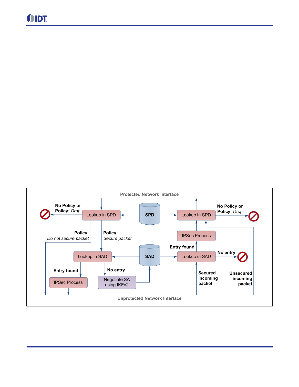
ZWIR451x Programming Guide
© 2016 Integrated Device Technology, Inc.
27
April 12, 2016
2.12.1. Internet Protocol Security (IPSec)
IDT provides an IPS ec implementation in conjunc tion with its communication libr a r ies. IPS ec is a pr otocol suite for
encryption and authentication of data sent over an IP network. IPSec is supported by virtually all modern
operating systems. The encapsulating security payload (ESP) and authentication header (AH) protocols are
supported for data encryption and authentication, respectively. Data encryption ensures confidentiality of
information transm itted over the network . Authenticatio n is applied to ensur e that data are not m odified along the
way and that the sender is the entity that it claims to be.
In order to use th e securit y features of the s tack, the libZWIR45xx-IPSec.a library must be included in the proj ect
and must be configured ap propriately. IPSec m aintains a Securit y Policy Database (SPD) that contains rules for
how outgoing and incoming traffic must be handled. For each incom ing an d out go i ng pac ket, the stack c hecks the
SPD for a matchin g rule that contai ns inf ormation on how the pack et should b e hand led. The r ules ca n dire ct the
network stack to either drop, b ypass or pr oc ess the pac ket in the security module. Bypassin g a pac ket means that
no security processing is applied. Rules can be applied to single addresses or complete subnets.
Each item in the SPD requiring security processing contains a pointer into the Security Association Database
(SAD). Each item of this database contains the required information for encryption and decryption of packets. This
information includes keying material and the algorithm to be used for encryption and decryption.
Figure 2.6 Working Principle of IPSec
Page 28

ZWIR451x Programming Guide
© 2016 Integrated Device Technology, Inc.
28
April 12, 2016
The SAD items can be configured manually or automatically. For automatic configuration, the Internet Key
Exchange protoco l is used. This protocol is im plemented in a separate libr ary and is described in the f ollowing
section. In either case, SPD entries for incom ing and outgoing traf fic must be conf igured by the applicat ion. This
is done using the function ZWIRSEC_AddSecurityPolicy. If manual configuration should be used, the
function ZWIRSEC_AddSecurityAssociation must be called on both communicating devices, setting the
security parameters for the connection.
2.12.2. Internet Key Exchange Version 2 (IKEv2)
The Internet Key Exchang e version 2 protocol can be used for autom atic creation of keying m aterial for secured
connections. This protocol is implemented in the libZWIR45xx-IKEv2.a library. If IKEv2 is used, no manual
configuration of the SAD is required. Instead, keying material is negotiated automatically on demand. If
application code attempts to send data to a remote node and the corresponding SPD entry requires security
processing of this data , it is c hec ked to determine if a s ec urit y assoc i ation (SA) is as s igned to the SPD entry. If no
entry exists, IPSec requests the establishment of a security association from the IKEv2 daemon.
IKEv2 first attempts to set up a secur e communication channel over which keying m aterial is exchanged. This
channel is set up using the Diffie-Hellmann-Key-Exchange algorit hm.
Both communicating parti es use a Pre-Share d Key (PSK) for mut ual authentication. T he PSK is registered us ing
the ZWIRSEC_AddIKEAuthenticationEntry function. After setup of the secure channel, k eying material for
the security association to be created is exc hang ed.
2.12.3. Recommendations
IDT str ongly recomm ends using the sec urity featur es prov ided b y the network stack . Security is n ot onl y required
to prevent data from being visible for third parties—more critical is active att acks on a network. Most applica tions
will suffer from s uch attacks. In the best case, applications might behave erratica lly; however, in the worst case,
perilous behavior of actors can be caused by an attack. Attacking possibilities are manifold: packets can be
changed on their way to the destination; they can be sent again; invalid packets infiltrate into the network; or
packets can be simpl y bloc ked by an attacker. IPSec can pr ot ec t aga ins t a ll of these attacks . IPSec in conj un c tion
with IKEv2 further increases the security, as the keying material can be renewed on a regular basis.
2.13. Firmware Over-the-Air Updates
IDT provides an over-the-air update (OTAU) librar y. This library extends the ap plication with functiona lity for the
reception and processin g of update packets, as well as f unctionality for replacing the existing code with a new
version. The update mechanism incorporates recovery mechanisms, ensuring the proper recovery after occurrence of an error during the update process.
The OTAU firmware library is des igned to require minimal interaction of the firm ware programmer. However, it
places some constraints on the firmware in order to ensure reliability of the OTAU function.
Page 29

ZWIR451x Programming Guide
© 2016 Integrated Device Technology, Inc.
29
April 12, 2016
.
update_code
(OTAU Boot-Loader)
.status_seg
(OTAU Status Information)
.text
.data
...
(Active Application Firmware)
.text*
.data*
...*
(New Application Firmware Image)
Optional section for permanent
parameter storage
2.13.1. Functional Description
Integrating the firm ware over-the-air update (OTAU) adds two com ponents into the us er applic ation. The f irst one
is a service for the r eception and processing of OTAU-related network tr affic. The second one is a boot -loader
that replaces the old firmware image with the new one after complete reception and verification of all update
traffic. The boot-loader com ponent is located in a program section called .update_code. The location of this
segment
A second segment that is ded icated to OTAU-enab led code is the .status_seg. This segm ent resides directly
behind the boot-loader component and stores status information about the firmware update.
Including the sections referenced abo ve, the application’s memory layout would be as shown in Figure 2.7. The
application code is located after the .update_code and .status_seg sections. Optionally the OTAU m emory
layout can incorporate a section for the storage of permanent parameters. This section
of the flash. In contrast to non-OTAU-enab led applica tions, the amount of memory availab le for the applicat ion is
limited to less than one half of the microcontroller’s total flash memory s ize. This is because the spac e for the
buffering of the full new firmware image must be provided.
The OTAU network service is started through a call to the ZWIR_OTAU_Register function. The f unction takes
the UDP port to be use d b y the OT AU networ k s ervice as the argument . Calling t his f unction is all that is requir ed
to enable the reception and proc essing of firmware over-the-air updates. All oth er update parameters are controlled by the update server, which is typically a computer in the network.
MUST be the first flash memory page(s). During the update process, the boot-loader is not replaced!
MUST be located at the end
Figure 2.7 Memory Layout of OTAU-Enabled Applications
Page 30

ZWIR451x Programming Guide
© 2016 Integrated Device Technology, Inc.
30
April 12, 2016
A new firmware image to be loaded into the device is typically received in small chunks of data. Whenever a
chunk of data is received, the c orresponding flash location in the new applicat ion firmware image portion of the
flash is updated. If this is the firs t chunk written to a flash page, the flash page i s completely erased before the
chunk is written to it. All packets corresponding to the same firmware update
information and the size of data chunk s
MUST be the same for all packets. Packets containing fragments of a
MUST include the same version
different size than the f irst fragment are ignored once the update is started. Packets containin g different version
information trigger a complete re-initialization of the update.
2.13.2. Firmware Constraints
The OTAU network service uses a dedicated UDP port for the reception and transmiss ion of OTAU-related packets. The application
application behavior is determined by the behavior of sockets being reopened with the same parameters.
The contents of the .update_code and .status_seg segm ents must not be changed in any way by the application. This means the application
MUST NOT use the same port for any other purpose. If this limitation is ignored, the
MUST NOT explicitly place functions or data in either of these sections!
In order to allow the OTAU from a firmware-version A to a firmware version B, t he firmware ver sions
MUST share
the following properties:
• The call stack of A and B must be located at the same RAM position.
• The call stack of A and B must be of the same size.
• The flash memory layout of A and B must be the same (e.g., no optional section as shown in Figure 2.7
can be added or removed).
2.14. Memory Considerations
Applications must manage their memory consumption – especially with respect to RAM (random access
memory). There are basically three components that contribute to the overall RAM size requirements of the
application:
1. Statically allocated memory
2. Dynamically allocated memory
3. Call stack
The call stack is required by the app lication to st ore the return ad dresses from f unction calls, func tion argum ents,
and variables stored loc ally in functio ns. The RAM size res erved for the cal l stack can be configured in th e linker
script. Applications utilizing IDT’s network stack need a minimum of 2kB of call stack . In order to leave some
flexibility for the user ap plic atio n, th e def aul t s tac k si ze conf igur ed i n the linker script is 5kB. The call stack resides
at the lower end of the RAM area.
Static memory is consumed by globally declared and local statically declared variables. IDT’s network stack
requires less t han 8kB of static m em or y in a m inimal c onfigurat ion. T he stat ic m em ory consum ption ca n eas il y be
determined b y exam ining the m ap file generated b y the linker. Stat ic m emory is allocate d immediately behi nd the
call stack.
Page 31

ZWIR451x Programming Guide
© 2016 Integrated Device Technology, Inc.
31
April 12, 2016
ZWIR_spRoutingTableSize
ZWIR_spNeighborCacheSize
ZWIR_spMaxSocketCount
The third component, t he dynamic ally allocated m emory, is allocat ed in the unused ar ea between stat ic memory
and the end of RAM. Memory in this area is t ypicall y all ocate d at runtime u sin g C’s malloc func tio n. M em ory can
be freed using the free function. Some list s and buffers used by IDT’s network stack are allocat ed dynamically.
There is no tool support for automatic determination of the dynamic m emory size requirements of applications.
The size of dynamic memory used by IDT’s network stack depends on the configured parameters. This is
explained in more detail in section 2.14.2.
2.14.1. Call Stack
IDT’s network stack plac es the call stack of t he application a t the lo wer end of the RAM. T his is enables detection
of s tack overflows. The s tack grows downwar ds from its topm ost address toward s the beginning of the R AM. If a
stack overflow occ urs , the MCU tri es to ac c ess an a d dr ess that is not in the RAM area and the M CU w il l gener at e
a Bus-Fault interrupt. Not e that during interrupt handling, the interrupt handl er function does not hav e a working
stack. Thus, it is not secure to use loca l variables or calling subroutines. The Bus-Fault interrupt def ault handler
performs a system reset.
2.14.2. IDT Network Stack Dynamic RAM Requirements
IDT’s network stack has a number of configurable parameters that require allocation of memory at runtime. During
system startup and aft er re set, memory for these var iables is alloc ated d ynam ically on the heap. Table 2.7 shows
on how these parameters influence the dynamic RAM requirements of the application.
Table 2.7 Stack Param et er Dynam i c Memo ry Size R equ rie m en ts
Note: The “Size” column specifies the size of a single element. It must be multiplied with the configured parameter value. For
each row, an additional 32-byte element is required for storing the allocation record if not otherwise noted.
Parameter Size Element Count Notes
[bytes] Min Default
28 1 8
60 1 8
28 4 8
- 238 - 6 This memory is allocated for internal
- 48 - 2
buffers for which size cannot be
configured.
In addition to t he quas i-stat ical l y a lloca ted memories above, IDT’s network stack dynamically allocates m emory at
runtime if packets must be sent to des tinations for which addr ess resolution an d route discovery have not been
performed. One pack et can be buffered for each destination node. Allocation is perform ed if enough memory is
available. If no mem ory is left, the packet to be sent is dropped , but the address resolution and rou te detection
procedure is initiated in any case. Thus, even if the packet is not being buffered, the next pac ket being sent is
likely to arrive at the destination node.
Page 32

ZWIR451x Programming Guide
© 2016 Integrated Device Technology, Inc.
32
April 12, 2016
6kB Heap Memory
Application developers must always ensure that the parameter settings allow proper al location of all quasi-static
memory. If parameters are chosen too large, stack initialization will fail and report the failure as error
ZWIR_eMemoryExhaustion. The default handling of this error is a system reset. Thus, if the parameters
causing the mem ory exha ustion are set during system startup, this will result in an infinit ive loop. The error is
detected easily with a custom implementation of the ZWIR_Error function.
2.14.3. Using Dynamic Memory Allocation
Applications requiring d ynamic memory allocation can f reely use the functions malloc and free for allocation
and de-allocation of RAM at runtime, respectively. However, the application developers must be aware of the
limited availabilit y of RAM on the device. Each allocat ed block c onsumes an addition al 32-byte bloc k on the heap
for the allocation record.
Due to memory fragmentat ion effects, it cannot be guaranteed that memory alloc ation is successful, even if the
total amount of free he ap space is sufficient f or an allocation requ est. If memory block s are allocated and freed
frequently, the free spac e in memory might become scattered over the whole he ap, not providing an y free block
large enough for holding a requeste d block. Figure 2.8 demonstrates this with a simple example that has 3kB of
free memory but does not allow the allocation of a 2kB memory block with malloc.
Figure 2.8 Heap Memory Scattering
M1 – 2kB
Memory blocks have been allocated in the order
M1 M2 M3
M2 was freed after M3 had been allocated.
M2 – 1.5kB
M3 – 1kB
M4 has never been allocated
3kB of free memory remaining, but allocation of
2kB block is not possible
M4 – 1.5kB
Page 33

ZWIR451x Programming Guide
© 2016 Integrated Device Technology, Inc.
33
April 12, 2016
2.15. Supported Network Standards
Table 2.8 lists RFCs that are supported b y IDT’s network stack, and it specifies the limitations that apply with
respect to these RFCs.
Table 2.8 Supported RFCs and Limitations
RFC Limitations
Internet Protocol Version 6 (IPv6) Specification
2460
Security Architecture for the Internet Protocol
4301
• Hop-by-hop options header
o Only Pad1 and PadN options are supported (as specified in RFC).
o Other options will cause unrecognized option processing as proposed in RFC.
• Routing extension header
o If “Segments Left” > 0, packets are ignored and an Internet Control Message Protocol (ICMP) error
message parameter problem is sent. However, the use of the type 0 routing header has been
deprecated by RFC 5095!
• Fragmentation extension header
o Not supported – packets received with this extension header are silently dropped.
o Specification requirement of receiving 1500-byte packets is not supported. However, use of
fragmentation is discouraged by the RFC!
• Destination options header
o Only Pad1 and PadN options are supported (as specified in RFC).
o Other options will cause unrecognized option processing as proposed in RFC.
o Packets with next header 59 are dropped.
o Traffic class and flow label are always set to zero in packets sent from 6LoWPAN nodes.
• Tunnel mode is not supported.
• ESP SA with both null encryption and no integrity algorithm is allowed.
• Events are not logged.
• Local IPv6 address cannot be used as a selector.
• No sequence counter overflow handling.
• SA lifetime is handled by IKE and only time controlled.
• Certificates are not supported for IKE authentication.
• No ICMP error messages processing and generation.
• Fragmentation and reassembly is not supported.
IP Authentication Header
4302
• AH is not supported.
Page 34

ZWIR451x Programming Guide
© 2016 Integrated Device Technology, Inc.
34
April 12, 2016
RFC Limitations
IP Encapsulating Security Payload (ESP)
4303
Cryptographic Algorithm Implementation Requirements for ESP and Authentication Header (AH)
4835
Neighbor Discovery for IP Version 6 (IPv6)
4861
• SPI 0 to 255 are not reserved.
• Anti-replay service is not active.
• The sequence number will cycle.
• ESN is not supported.
• Dummy packets are not supported.
• Traffic flow confidentiality (TFC) padding is not supporte d.
• Auditing is not supported.
• Supports ONLY NULL encryption and AES-CTR.
• Supports ONLY NULL authentication and AES-XCBC-MAC-96.
• Only host functionality is implemented.
• Destination cache as proposed by the standard is not available. However, there is no need for this as the
purpose of the cache is to reduce the time required for the next hop determination, but this is already
done in a fraction of the time that message transport requires.
• No checking of the linkMTU option is performed – however this is not required as 6LoWPAN only
supports the minimum linkMTU of 1280 and never sends larger packets.
• If no reachable router is in the router list, default router selection is not performed in a round-r obin manner
as proposed by the standard; instead the first entry found is taken. However, reachable routers still have
precedence over routers whose reachability is unknown (see section 6.3.6 of RFC4861).
• Variables are mainly implemented as constants.
• During address resolution, packets must be queued until address resolution is complete. The memory for
this is allocated dynamically at runtime. If memory allocation fails, the packet is not queued! Only a single
packet will be queued. A queued packet is not replaced with the latest one if more than one packet needs
to be buffered during the address resolution process.
• Changes of the link-layer address are not advertised as proposed in section 7.2.6 of RFC4861. However,
this is not required, as the node will also change its IPv6 address.
• Anycast neighbor solicitation is not supported.
• Redirect messages are not supported (see section 8 of RFC4861).
• Nodes that use multicast do not use the Multicast Listener Discovery (MLD) protocol to announce the
groups in which they are members.
IPv6 Stateless Address Auto-configuration
4862
• Maximum number of NS for DAD is limi ted to 1.
• Address deprecation is not implemented. Behavior is the same as preferredLifetime==validLifetime.
However, router advertisements with a preferredLifetime>validLifetime are ignored by the device.
Page 35

ZWIR451x Programming Guide
© 2016 Integrated Device Technology, Inc.
35
April 12, 2016
RFC Limitations
Transmission of IPv6 Packets over IEEE 802.15.4 Networks
4944
IPv6 Configuration in Internet Key Exchange Protocol Version 2 (IKEv2)
5996
• IDT’s implementation does not support one of the specified header compression algorithms proposed by
the RFC. Instead, it implements the RFC draft-hui-6lowapn-hc version 01 (see “6LoWPAN Compression
of IPv6 Datagrams” below).
is used as the dispatch value for this compression format.
03
HEX
• Mesh functionality specified in the RFC is not implemented. Instead, a proprietary link-layer mesh
implementation is provided.
• Only 64-bit link-layer addresses are supported at this time.
• Supports only the negotiation of an ESP in transport mode between two protected endpoints.
• The Diffie-Hellman group cannot be changed.
• Only one initial exchange can occur at the same time.
• Only one pair of child SAs can be negotiated with one IKE SA.
• Windowing is not supported.
• Timeouts are defined by user.
• The critical flag is ignored.
• Cookies are not supported.
• Implementation provides only one proposal.
• Only packets for port 500 are accepted.
• Extensible Authentication Protocol (EAP) is not supported.
• IP Compression (IPComp) is not supported.
• Network address translation (NAT) traversal is not supported.
• Only ID_IPV6_ADDR is supported.
• Only shared key message integrity code is supported.
• Vendor ID payload is not supported.
• Configuration payload is not supported.
Cryptographic Algorithms for Use in the Internet Key Exchange Version 2 (IKEv2)
4307
6LoWPAN Compression of IPv6 Datagrams
draft-hui-
6lowpan-
hc-01
• Supports only 768 MODP (Modular Exponential) Group.
• Supports only ENCR_AES_CBC.
• Supports only PRF_AES128_CBC.
• Supports only AUTH_AES_XCBC_96.
• ISA100_UDP Header Compression is not implemented (see section 3.3 in draft specification).
Page 36

ZWIR451x Programming Guide
© 2016 Integrated Device Technology, Inc.
36
April 12, 2016
3 Core-Library Reference
3.1. Initialization
The core library provides two differ ent hooks that can be used to initi alize the application during s ystem startup.
The first hook, nam ed ZWIR_AppInitHardware, is called bef ore network initialization. T he second one , named
ZWIR_AppInitNetwork, is called afterwards.
void
ZWIR_AppInitHardware ( ZWIR_ResetReason_t resetReason )
This hook is called after power on and after reset to conf igure the module periph erals. The resetReason
argument specifies the res et source that triggered the exec ution of this function. If requir ed, the operating
mode of the module
Note: Most API functions must not be called from this function. The documentation specifies which API
functions can be called from ZWIR_AppInitHardware.
SHOULD be set from this function.
void
ZWIR_AppInitNetwork ( ZWIR_ResetReason_t resetReason )
This hook is called when the def ault network ing parameter s have been init ialized af ter power-on or reset. It
should be used to open sock ets and initialize further network parameter s if required. However, it m ust not
be used for sending out d ata, as the node has not com pleted Duplicate Addr ess Detection ( DAD); refer to
section 2.8.4 for further details) at this point. The resetReason argum ent specifies the reset source that
triggered the execution of this function.
void
ZWIR_AppInitNetworkDone ( ZWIR_ResetReason_t resetReason )
This hook is called after successful completion of the DAD procedure. It is also called when DAD is
disabled. In this case, the function is called immediately after the call to ZWIR_AppInitNetwork. The
resetReason argument specifies the reset source that triggered the execution of this function. All API
functions can be called from this function.
void
ZWIR_SetOperatingMode ( ZWIR_OperatingMode_t opMode,
ZWIR_RadioReceiveCallback_t callback )
This function sets the operatin g mode of the device. Device Mode, Gateway Mode, or Sniffer Mode can be
selected (refer to section 0) with the opMode argument. The callback argument is used in Gateway Mode
and Sniffer Mode to specif y the function to be called on the rece ption of data. If the callback is NULL, no
function will be called. If Device Mode is selected callback is ignored. It is
ZWIR_SetOperatingMode only be called from ZWIR_AppInitHardware.
RECOMMENDED that
Page 37

ZWIR451x Programming Guide
© 2016 Integrated Device Technology, Inc.
37
April 12, 2016
typedef enum { ... } ZWIR_OperatingMode_t
Type enumerating the different operating modes of the device. Possible values include:
ZWIR_omNormal Device Mode
ZWIR_omGateway Gateway Mode
ZWIR_omSniffer Sniffer Mode
typedef enum { ... } ZWIR_ResetReason_t
Type enumerating the different reasons for system reset. Possible values include:
ZWIR_rPowerOnReset
Reason: The device has been powered on after being switched off.
ZWIR_rStandbyReset
Reason: The device is waking up from standby mode
ZWIR_rIndependentWatchdogReset
Reason: The MCU’s independent watchdog (IWDG) was triggered.
ZWIR_rSoftwareReset
Reason: A software reset has been performed
ZWIR_rPinReset
Reason: System reset was triggered by pulling low the reset pin.
ZWIR_rWindowWatchdogReset
Reason: The window watch dog has trig gere d
ZWIR_rLowPowerReset
Reason: The supply voltage dropped below the specified threshold.
3.2. Program Control
The API does not provid e the c oncept of a centr al m ain f unction as is typic al in traditional C pr ogram s. Only three
timing-driven hooks, nam ed ZWIR_Main10ms, ZWIR_Main100ms, and ZWIR_Main1000ms, are provided; they
are called periodically after 10, 100 and 1000 milliseconds, respectively. Sensing and acting by the user
application should be implemented in these hooks. For more fine-tuned time control, a user-programmable
callback timer is ava ilable. This timer can be programm ed at 1ms increments. Initialization and de-initialization of
this freely programmable timer function is via ZWIR_StartCallbackTimer and ZWIR_StopCallbackTimer.
The ZWIR_Main10ms, ZWIR_Main100ms, and ZWIR_Main1000ms hooks can be defin ed to im plem ent ap plication behavior that has to be executed periodically. The default implementations of these hooks do nothing, so
these hooks can be left undefined if they are not required.
Page 38

ZWIR451x Programming Guide
© 2016 Integrated Device Technology, Inc.
38
April 12, 2016
In addition to the f ixed per iod m ain f unctions, th e API also pro vides a f reel y confi gurable c allbac k tim er. T he timer
is started using the ZWIR_StartCallbackTimer function. It is possible to provi de a data pointer to this function,
which is passed to t he callback when the timer expir es. This allows for delayed data processing. Whether the
timer is triggered just once or periodically can be selected.
The timer is stopped with the ZWIR_StopCallbackTimer.
void
ZWIR_Reset ( void )
This function causes a s of t w are r es et of th e system. Both, the m ic roc ontr oller an d the tr a nsc ei ver ar e res e t.
The complete startup sequence is executed. If this function is called while the transceiver receives or
transmits data, the packet will be lost.
void
ZWIR_ResetNetwork ( void )
This function resets the r adio transceiver and reinitializes the net work stack. After a call to this functio n,
IPv6 address auto-conf iguration is restarted and manually ass igned addresses are lost. Also routing an d
address resolution information are lost.
void
ZWIR_Main10ms ( void )
void
ZWIR_Main100ms ( void )
void
ZWIR_Main1000ms ( void )
These hooks are calle d with a period of 10, 100 and 1000 m illiseconds. On timeslots that are multiples of
10ms or 100ms, the shorter period function has priority over the longer period. This means that
ZWIR_Main10ms is called before ZWIR_Main100ms, whic h is c al led bef ore ZWIR_Main1000ms. A ll thr e e
functions are called immediately at system startup.
Note: These functions are not suitable if exact timer behavior is required. A constant execution interval
cannot be guaranteed nor is it guaranteed that the function is executed at each intended time instant.
Page 39

ZWIR451x Programming Guide
© 2016 Integrated Device Technology, Inc.
39
April 12, 2016
void
ZWIR_StartCallbackTimer ( uint32_t timeout,
ZWIR_TimeoutCallback_t callback,
void* data,
bool periodic )
If this function is called, the freel y programmable tim er is initial ized and started. T he function pr ovided with
the callback argument will be called about timeout ms after the call to ZWIR_StartCallbackTimer.
The value provided with data will be passed t o callback when it is c alled. If t he periodic flag is set to
one, callback is called periodically; otherwise callback is c alle d jus t onc e. If this function is call ed whi le
the timer is running, the timer will be reprogrammed and the previous programming will be lost.
Note: The callback timer is not suitable if exact timer behavior is requ ired. Cons ider using a MCU timer
peripheral for exact timing.
void
ZWIR_StopCallbackTimer ( )
This function stops a running callback timer. If no timer is running, nothing will happen.
void
ZWIR_TriggerAppEvent ( uint8_t eventId )
This function allows the processing of application events with a certain operating system priority. This
function notifies the operating system of the presence of an application event and schedules the
appropriate callbac k f unction f or exec ution. T ypicall y this is use d to exec ute c om putation al ly i ntensiv e cod e
in response to an interrupt.
void
ZWIR_RegisterAppEventHandler ( uint8_t eventId,
ZWIR_AppEventHandler_t handler )
This function registers an appl ication event han dler callback for a certain applicati on event in the operat ing
system. If this function is called m ore than once with the same eventId, the call back function provided
with the last call will be in effect.
typedef void ( * ZWIR_AppEventHandler_t ) ( void )
This function pointer t ype defines the signature of a callbac k function that is ex ecuted in response to an
application event.
typedef void ( * ZWIR_TimeoutCallback_t ) ( void* data )
Function pointer type for the callback function that should be called if the callback timer expires.
Page 40

ZWIR451x Programming Guide
© 2016 Integrated Device Technology, Inc.
40
April 12, 2016
ZWIR_RevisionInfo_t
ZWIR_GetRevision ( void )
This function returns a st ructure containing d etailed vers ion information. This information must be provided
if support requests are sent to IDT.
typedef struct { int8_t majorRevision
int8_t minorRevision
int16_t versionExtension } ZWIR_RevisionInfo_t
Type for objects carr ying version information. If problem s are encountered while using the stack , request
this structure using ZWIR_GetRevision and provide the information obtained to IDT with an error report.
void
ZWIR_NetEventCallback ( ZWIR_NetEvent_t event )
This function is called when a network event occ urs. The event type is pas sed in the ZWIR_NetEvent_t
event argument.
typedef enum { ... } ZWIR_NetEvent_t
Net events enumeration type accepted by ZWIR_NetEventCallback. Possible values:
ZWIR_neAppReceive
Event: UDP receive callback function is called.
ZWIR_neAppTransmit
Event: UDP transmit function is called.
ZWIR_neIPv6Receive
Event: IPv6 stack receive function is called.
ZWIR_neIPv6Transmit
Event: IPv6 stack transmit function is called.
ZWIR_neMACReceive
Event: Receiver receive function is called.
ZWIR_neMACTransmi
Event: Receiver transmit function is called.
Page 41

ZWIR451x Programming Guide
© 2016 Integrated Device Technology, Inc.
41
April 12, 2016
bool
ZWIR_Error ( int32_t errorCode )
This function is called when a recoverable library error is encountered. The error-code is passed in the
errorCode argument. If true is returned, the err or is assum ed to be pr oces sed and no action will b e tak en
by the stack. If false is returned, the default error handler will be executed.
int32_t
ZWIR_Rand ( void )
This function returns a random number. The sequence of numbers generated by this functio n is actually
only pseudo-random , as a linear feedback shift r egister with a generator polyno mial is used. However, by
calling ZWIR_SRand with zero as ar gument, the random num ber generator is seeded with a true random
number.
int32_t
ZWIR_SRand ( int32_t seed )
This function seeds the random number generator. If zero is provided as seed, a true random number is
generated from therm al noise. Any value other than zero is used to initial ize the generator directly. This
allows creating reproduc ible application behavi or for debug purposes. Using non-zero seed values i n production code is not recommended.
3.3. Networking
A ZWIR451x node can join any IPv6 network. Each devic e automatically gets an IPv6 addr ess that is computed
from the link-la yer address of the module. Addi tionally, the user’s own IPv6 ad dresses can be assigned to th e
module. The modules can communicate bidirectionally using the UDP protocol.
3.3.1. Address Management
The API provides a set of func tions for managing th e different addresses of a 6LoWPAN module. A m odule has
three different types of addresses: the PAN identifier, the link-layer address, which is also called the PAN
address, and a set of IPv6 addresses.
3.3.1.1. PAN Identifier
The PAN identifier is a 16-bit value that determ ines the personal area network that the m odule belongs to. All
devices in a PAN must have the sam e PAN identifier. Dev ices with differ ent PAN identifiers cannot c ommunicate
with each other. They cannot even use each other as a network relay. Each device has exactly one PAN
identifier. It can be read and altered using the ZWIR_SetPANId and ZWIR_GetPANId functions, respectiv ely.
The default value of the PAN identifier is ACCA
HEX
.
Page 42

ZWIR451x Programming Guide
© 2016 Integrated Device Technology, Inc.
42
April 12, 2016
uint16_t
ZWIR_GetPANId ( void );
Reads and returns the PAN identifier of the module.
void
ZWIR_SetPANId ( uint16_t panId );
Sets the PAN identifier of the node to the value provided in panId. The value is retained until the next reset
or until Standb y Mode is entered. After waking up, the factory-program med value is active again until the
next call to this function.
3.3.1.2. Link-Layer Address
The link-layer addres s, also calle d the PAN address, is a 64-bit-wide value that identif ies the device in the PAN.
All communication b etween devices in a PAN is based on the link -layer address . Higher la yer protoco ls, such as
IPv6, resolve the ir addresses into link-layer addresses. A globa lly unique link-layer address is programmed into
each device during m anufacturing. Changing this address is not recommended, as this could caus e the address
to be no longer unique. N evertheless, the functions ZWIR_SetPANAddress and ZWIR_GetPANAddress allow
reading and writing the PAN address.
ZWIR_PANAddress_t const*
ZWIR_GetPANAddress ( void )
Reads and returns the link-layer address of the module.
void
ZWIR_SetPANAddress ( ZWIR_PANAddress_t const* panAddress )
Sets the link -layer address to the value provided in panAddress. Changing the link-layer addr ess of the
module is not recommended for the reasons given in section 2.8.4. However, if manual assignment of
addresses is require d, calling ZWIR_SetPANAddress from ZWIR_AppInitHardware is recommended.
The assigned panAddress value is retained unti l the nex t system r eset or deep s leep. Af ter wak ing u p, the
factory-programmed value is active again until the next call to this function.
Note: Changing the link-layer address of a device during normal operati on will typically cause a loss of all
incoming packets for a period of time. The standard all ows sending unsolicited ne ighbor advert isem ents as
an option if the link-layer address changes. This feature is not included in IDT’s 6LoWPAN stack.
typedef uint8_t ZWIR_PANAddress_t [8]
Data type for represen tation of link-layer address es. Bytes are stored in netw ork byte order, which is big
endian. This means that the highest-order byte is stored first.
Page 43

ZWIR451x Programming Guide
© 2016 Integrated Device Technology, Inc.
43
April 12, 2016
3.3.1.3. IPv6 Addresses
Although manual assignment of IPv6 addresses is not required by most applications, the API provides the
function ZWIR_SetIPv6Address. T his f unction c an b e used to as sign ad ditio nal IPv6 addr esses to an interface.
Up to three addresses can be assigned in total, but the first address is always allocated by the automatically
configured link-local address. The function ZWIR_GetIPv6Addresses can be used to request all addresses
assigned to an interface.
The ZWIR_CheckMulticastGroup hook is c alled if a multicast packet is receiv e d that does not belon g to th e al l
nodes multicast group or the nod e solicited address multicast group. This function must be im plemented by the
application if multicast addressing is used.
bool
ZWIR_SetIPv6Address ( ZWIR_IPv6Address_t const* ipv6 )
Add the address provided in ipv6 to the network interf ace.
The function returns true if the operation was successful or false otherwise. The function fails if the
maximum number of IPv6 addresses is assigned to the interface already.
uint8_t
ZWIR_GetIPv6Addresses ( ZWIR_IPv6Address_t const* ipv6Buffer,
uint8_t maxCount )
Request a set of address es as s igned t o the int erface. The ipv6Buffer argument must carry a pointer that
points to a buffer that is able to store at most maxCount IPv6 addresses. T he f unction will s tore maxCount
addresses in this buffer if the interface has at least maxCount addresses assigned. If the number of
assigned address is lo wer than maxCount, the func tion will store all ava ilable addr esses. The return value
determines the number of addresses that have actually been stored. Thus, if 0 is returned, the interface has
no IPv6 address assigned. This could be due to failing duplicate address detection (DAD).
void
ZWIR_SetDestinationPANId ( uint16_t pandID )
This function is used for changing th e destination PAN identifier temporaril y. The configured value rem ains
in effect until ZWIR_ResetDestinationPANId is called or the device is reset.
Page 44

ZWIR451x Programming Guide
© 2016 Integrated Device Technology, Inc.
44
April 12, 2016
void
ZWIR_ResetDestinationPANId ( void )
This function res ets the PAN identifier of the de vice to the last value th at had bee n conf igured bef ore it was
changed using ZWIR_SetDestinationPANId.
bool
ZWIR_CheckMulticastGroup ( ZWIR_IPv6Address_t const* ipv6 )
This hook is called whenever a multicast packet is received that contains a multicast group that is not
known by the network stack . The user im plem entation m ust decide if the node is part of the multicast group
provided with the multicas t group ID (t he low er 112 b ytes) in the IP v6 addres s. True must be returned if the
node belongs to the multicast group, false otherwise.
typedef union { uint8_t u8 [ 16 ],
uint16_t u16 [ 8 ],
uint32_t u32 [ 4 ] } ZWIR_IPv6Address_t
Data type for representa t ion of IPv6 addresses. B ytes are s tor ed in n et work b yte or der, wh ich is b ig end ian;
i.e., the highest-order byte is stored first. Therefore using the u16 or u32 elements might cause unexpected
results especially when printing. Consider changing the byte order if host byte order is required.
3.3.2. Socket and Datagram Handling
The functions ZWIR_OpenSocket and ZWIR_CloseSocket are provided for opening and closing sockets,
respectively. Datagrams are sent over sockets using the ZWIR_SendUDP, ZWIR_SendUDP2 and
ZWIR_Send6LoWPAN functions, depending on the operating mode of the device.
Incoming datagram s are handled by user-defined callback f unctions, which must be to be ass igned to sockets
using the ZWIR_OpenSocket function. The API functions ZWIR_GetPacketSenderAddress,
ZWIR_GetPacketDestinationAddress, ZWIR_GetPacketSenderPort and ZWIR_GetPacketHopCount
are provided for requesting the address and port of a sender.
Page 45

ZWIR451x Programming Guide
© 2016 Integrated Device Technology, Inc.
45
April 12, 2016
ZWIR_SocketHandle_t
ZWIR_OpenSocket ( ZWIR_IPv6Address_t const* remoteAddr
uint16_t remotePort,
uint16_t localPort,
ZWIR_RadioReceiveCallback_t rxHandler )
This function opens a new socket t o a remote host. The remoteAddr and remotePort arguments spec ify
the IPv6 address and t he UDP port of the rem ote host, respectivel y. The localPort argument s pecifies
the port on which incom ing data is acc epted. If localPort is set to zero, an unused port fr om the range
from 4096 through 32000 is c hosen. If incoming data should be rec eived, a pointer to a callback function
must be passed in the rxHandler argument. If no data is expected, the va lue of localPort does not
matter and rxHandler must be set to N ULL. In order to recei ve packets from arbitrar y remote hosts, the
unspecified address can be passed to the function. In this case, the socket is not suitable for sending
packets.
On success, the func tion returns a socket hand le that can be used w ith datagram handling f unctions. The
function fails if the m aximum number of socket s is alread y opened or if a sock et with the sam e param eters
for remoteAddress and localPort already exists. In this case NULL is returned.
void
ZWIR_CloseSocket ( ZWIR_SocketHandle_t socket )
Open sockets are clos ed using this function. If a socket is invalid or has alrea dy been cl osed, the function
has no effect. Closing a socket has no eff ect on any previous l y sent pack ets, even if transm iss ion is not yet
completed.
bool
ZWIR_SendUDP ( ZWIR_SocketHandle_t socket,
uint8_t const* data,
uint16_t length )
UDP datagrams are sent over a specific socket using this function. The socket denoted by the socket
argument determines the destina tion addr ess and p ort of the datagr am. The data and length arguments
specify the payload. The m aximum packet s ize is 1232 b ytes. The function r eturns a non-zero value if the
packet to be sent was successfully queued in the output queue; otherwise zero is returned. If zero is
returned, there is not en ough room in the output queue to buffer this pac ket. In this case, c ontrol must be
passed back to the operating system.
Note: A non-zero return value does not automatically denote the successful delivery of the packet.
Successful delivery can only be verified by response packets sent on the application level.
Note: Calling this function in a while l oop waiting for a non-zer o result will deadlock the s ystem if a pac ket
cannot be queued. After a zero result, c ontrol must always be passed to t he operating system . Otherwise
the output buffers will never be freed and this function continues to fail, resulting in a deadlock.
Note: This function cannot be used in the Gateway Mode; use ZWIR_Send6LoWPAN when in Gateway
Mode!
Page 46

ZWIR451x Programming Guide
© 2016 Integrated Device Technology, Inc.
46
April 12, 2016
bool
ZWIR_SendUDP2 ( uint8_t* data,
uint16_t size,
ZWIR_IPv6Address_t* remoteAddress,
uint16_t remotePort )
This function sends a n UDP packet without the need f or opening a socket. The destination addres s and
destination port are provided in the remoteAddress and remotePort ar guments. The l ocal UDP port is
selected arbitrarily by the network stack . T he maximum packet size is 1232 bytes. T he function returns a
non-zero value if the packet to be sent was successfully queued in the output queue; otherwise zero is
returned. If zero is returned , ther e is not e nou gh r oom in the output queue to buff er this pac ket. In this case,
control must be passed back to the operating system.
Note: A non-zero return value does not automatically denote the successful delivery of the packet.
Successful delivery can only be verified by response packets sent on the application layer.
Note: Calling this function in a while l oop waiting for a non-zero result will d eadlock the s ystem if a p acket
cannot be queued. After a zero result, c ontrol must always be passed to t he operating system . Otherwise
the output buffers will never be freed and this function continues to fail, resulting in a deadlock.
Note: This function cannot be used in the Gateway Mode; use ZWIR_Send6LoWPAN when in Gateway
Mode!
ZWIR_IPv6Address_t const*
ZWIR_GetPacketSenderAddress ( void )
This function returns a pointer to the IPv6 source address of the last received packet. It can be used reliably
in the RX callback function. Using this function outside of the RX callback function might cause
unpredictable results.
Note: This function cannot be used in Gateway Mode.
ZWIR_IPv6Address_t const*
ZWIR_GetPacketDestinationAddress ( void )
This function returns a poi nter to the IPv6 destination address of the last received packet. It can be us ed
reliably in the RX callback function. Using this function outside of the RX callback function might cause
unpredictable results.
Note: This function cannot be used in Gateway Mode.
uint16_t
ZWIR_GetPacketSenderPort ( void )
This function returns the s ender port of the last rec eived pack et. It can be used reliabl y in the RX callback
function. Using this function outside of the RX callback function might cause unreliable results.
Note: This function cannot be used in Gateway Mode.
Page 47

ZWIR451x Programming Guide
© 2016 Integrated Device Technology, Inc.
47
April 12, 2016
uint8_t
ZWIR_GetPacketHopCount ( void )
Returns the number of hops the last received packet has taken.
Note: Using this function outside of the RX callback function might cause unreliable results.
int32_t
ZWIR_GetLastRSSI ( void )
Returns the receive signal strength indicator (RSSI). The value ap proximately corresponds to the receive
power level in dBm. Using this function outside of the RX callback function might cause unreliable results.
ZWIR_PANAddress_t*
ZWIR_GetSourcePANAddress ( void )
Returns the source PAN address of the latest received packet.
Note: Using this function outside the receive callback might cause unreliable results.
ZWIR_PANAddress_t*
ZWIR_GetDestinationPANAddress ( void )
Returns the destination PAN address of the last received packet.
Note: Using this function outside the receive callback might cause unreliable results.
ZWIR_SocketHandle_t
ZWIR_GetPacketRXSocket ( void )
Returns the socket handle of the socket on wh ich the last packet was received.
ZWIR_IPv6Address_t*
ZWIR_GetFailingAddress ( void )
Returns the last address for which address resolution failed. This function is typically called from
ZWIR_Error when the ZWIR_eHostUnrechable error was reported. If no address resolution error
occurred since the last reset, the result is undefined.
Page 48

ZWIR451x Programming Guide
© 2016 Integrated Device Technology, Inc.
48
April 12, 2016
bool
ZWIR_Send6LoWPAN ( ZWIR_PANAddress_t const* remoteAddr,
uint16_t const* data,
uint8_t const length )
This function is used t o send complete IPv6/UDP pack ets to the remote host with the link -local address
remoteAddr. No UDP or IPv6 header pr ocessing is p erformed on the p acket. Instead i t is passed direc tly
to the 6LoWPAN proces sing la yer. The data argument mus t point to the fir st header b yte of the IP v6/UDP
packet; length specifies the size including all headers. This is useful in conjunction with the Gateway
Mode.
Note: Calling this function in a while l oop waiting for a non-zero result will d eadlock the s ystem if a p acket
cannot be queued. After a zero result, c ontrol must always be passed to t he operating system . Otherwise
the output buffers will never be freed and this function continues to fail, resulting in a deadlock.
Page 49

ZWIR451x Programming Guide
© 2016 Integrated Device Technology, Inc.
49
April 12, 2016
typedef
void ( * ZWIR_RadioReceiveCallback_t ) ( uint8_t* data,
uint16_t length )
Function pointer type for the callback function that should be called on reception of data over an UDP
socket.
typedef
void* ZWIR_SocketHandle_t
Type representing a socket.
3.3.3. Radio Parameters
The radio module provides the capability to alter the physical radio channel a nd the tr ansm it output po wer. This is
accomplished using the ZWIR_SetChannel, ZWIR_SetModulation, and ZWIR_SetTransmitPower
functions. C hanges t o the radio param eters take effect imm ediately. T he changes are r eset b y ZWIR_Reset, but
not by ZWIR_ResetNetwork. Chang ing rad io param eters dur ing the tra nsm ission/recept ion of a pack et will ver y
likely cause the loss of the packet.
To verify the transc eiver pa ram eter , the corresponding get functi on ZWIR_GetChannel, ZWIR_GetModulation
or ZWIR_GetTransmitPower can be called.
void
ZWIR_SetChannel ( ZWIR_RadioChannel_t channel )
Sets the module to the radio channel specified by channel.
Note: If this is done while a tr ansmission or reception is ongoing, the tra nsm itted or received pack et will be
lost. It is recommended that this function be called from ZWIR_AppInitHardware.
Note: Local regul ations limit the use of the spectrum . The user
MUST only select channels that are allowed
to be used in the area where the application is going to be installed! Check with local authorities to
determine which part of the spectrum the application is allowed to use.
ZWIR_RadioChannel_t
ZWIR_GetChannel ( )
Returns the current ZWIR_RadioChannel_t channel
void
ZWIR_SetModulation ( ZWIR_Modulation_t modulation )
This function is used to change the modulation scheme to the value specified with the modulation
argument.
Page 50

ZWIR451x Programming Guide
© 2016 Integrated Device Technology, Inc.
50
April 12, 2016
Note: If this is done while a tr ansmission or reception is ongoing, the tra nsm itted or received pack et will be
lost. It is recommended that this function be called from ZWIR_AppInitHardware.
ZWIR_Modulation_t
ZWIR_GetModulation ( )
Returns the current ZWIR_Modulation_t modulation
void
ZWIR_SetTransmitPower ( int power )
Sets the transceiver outp ut power to the value sp ecified by power. T he valid range of values dep ends on
the channel being selected. In the European frequency band, a transmission power of -10dBm to 5dBm can
be selected; in the US band, -10dBm to 10dBm are permitted. Values that are too low or too high are
automatically adjusted to the closest valid value.
Note: If this is done while a tr ansmis sion is ongo ing, the transmitted pac ket is very likel y to be lost. For that
reason, it is recommended that this function be called only from ZWIR_AppInitHardware.
int
ZWIR_GetTransmitPower ( )
Returns the current transmit power.
typedef enum { ... } ZWIR_RadioChannel_t
Radio channel enumeration type accepted by ZWIR_SetChannel. Possible values include
ZWIR_channel0, ZWIR_eu868 EU Band, 868.3 MHz
ZWIR_channel1, ZWIR_us906 US Band, 906 MHz
ZWIR_channel2, ZWIR_us908 US Band, 908 MHz
ZWIR_channel3, ZWIR_us910 US Band, 910 MHz
ZWIR_channel4, ZWIR_us912 US Band, 912 MHz
ZWIR_channel5, ZWIR_us914 US Band, 914 MHz
ZWIR_channel6, ZWIR_us916 US Band, 916 MHz
ZWIR_channel7, ZWIR_us918 US Band, 918 MHz
ZWIR_channel8, ZWIR_us920 US Band, 920 MHz
ZWIR_channel9, ZWIR_us922 US Band, 922 MHz
Page 51

ZWIR451x Programming Guide
© 2016 Integrated Device Technology, Inc.
51
April 12, 2016
ZWIR_channel10, ZWIR_us924 US Band, 924 MHz
ZWIR_channel100, ZWIR_eu865 EU Band, 865.3 MHz
ZWIR_channel101, ZWIR_eu866 EU Band, 866.3 MHz
ZWIR_channel102, ZWIR_eu867 EU Band, 867.3 MHz
typedef enum { ... } ZWIR_Modulation_t
Enumeration of modulation schemes accepted by ZWIR_SetModulation. Possible values include
ZWIR_mBPSK Binary Phase Shift Keying
ZWIR_mQPSK Offset Quadrature Phase Shift Keying
3.3.4. Gateway Mode Functions
The ZWIR45xx network stack provides the Gateway Mode to allow easy implementation of network bridges.
Therefore, the stack only performs network processing up to and including the 6LoWPAN layer. Thus , when a
packet comes in, a full IPv6 packet is passed to the receive callback. This allows the implementation of a perfectly
transparent network bridge. However, if the bridge should be update able or configuration param eters should be
set remotely, it would be desirable to have the opportunity of performing higher layer processing of incoming
packets that are addressed to the bridge. For th is purpose, the types and f unctions defined in this section are
provided.
bool
ZWIR_GatewayProcessPacket ( uint8_t* data,
uint16_t size );
This function must be calle d to cause the network stack to process the network and higher layer protoc ols
of an incoming pack et. The function is intended t o be called from the receive c allback of Gateway Mode
devices. The data and size arguments of the receive callback should be passed unmodified to this
function.
void
ZWIR_GatewaySetOutputFunction ( ZWIR_GatewayOutputFunction_t fn )
Devices operating in Gateway Mode typically have more than one network interface. When higher layer
protocol processing is in plac e, it m us t be dec ided which net work interf ace is use d f or send ing ou t pac kets .
This decision must be dete rmined by an applicatio n callback that m ust be registered at the network s tack
using this function. NULL resets to default output function.
Page 52

ZWIR451x Programming Guide
© 2016 Integrated Device Technology, Inc.
52
April 12, 2016
typedef
uint8_t ( *ZWIR_GatewayOutputFunction_t ) ( uint8_t* data,
uint16_t size,
ZWIR_PANAddress_t* address );
This type defines the s i gn at ure of functions to be used as the output f unc ti on in G atewa y Mode. T he tas k of
this function is determining to which interface an outgoing packet must be sent and calling the
corresponding output functi on for this interfac e. The decision is t ypically based o n the PAN address of the
destination node that is provided in the address argument. The data argument carries a pointer to the
IPv6 packet to be sent; the size argument determines the size of this packet.
3.3.5. Miscellaneous
void
ZWIR_LocalBroadcast ( uint8_t value )
Disable or enable rebroadc asting of broadc ast packets to send a loca l broadcast. If enabled, all bro adcast
packets will be sent with the maximum hop count so they will not be rebroadcast.
Note: The usual way to use this funct ion is to enable the l ocal broadcast, t o send a broadc ast packet , and
to disable the local broadcast.
void
ZWIR_MulticastPreferExistingRepeater ( uint8_t value )
Disable or enable send ing broadcast packets that will be rebroadcasted by nodes with existing multi-hop
routes (repeater) onl y. If enabled all broadcast pack ets will only be rebroadcas t from devices with existing
multi-hop routes. This feature reduces the rebroadcast tr affic in larger network s and ensures that ex isting
repeaters are most likely to be used for multi-hop routes.
Note: If all retries of the route discovery and t he address resolution fail and the “multicast prefer existing
repeater” option is enabled , the route d iscovery and t he address r esolution wi ll restart and use all possib le
hop routes. This ensures communication during the network start up.
ZWIR_TRXStatistic_t
ZWIR_GetTRXStatistic ( void )
This function returns statistic information about transmission and reception. The returned data structure
contains the number of packets, the number of bytes received and transmitted, the number of
re-transmissions, and the number of CRC failures on reception. Furthermore, the transmit duty-cycle is
included. The counters are reset either on reset or if ZWIR_ResetTRXStatistic is called.
Checking the duty cycle should be performed on a regular basis in order to meet the duty cycle
requirements at the operation site of the device. Contact the local authorities to find out if duty-cycle
limitations apply in the target market(s).
Page 53

ZWIR451x Programming Guide
© 2016 Integrated Device Technology, Inc.
53
April 12, 2016
Note: All values in the s tr u c ture might be higher th an ex pected. This is due to t h e o verhe ad c om munication
that is required for address resolution and route discovery. Refer to section 2.10 to determine if it is
possible to optimize constant settings in order to reduce overhead traffic to a minimum.
void
ZWIR_ResetTRXStatistic ( void )
This function resets all values of the transceiver statistics to 0. This function has no effect on ongoing
transfers.
typedef struct {
uint32_t txBytes
uint32_t txPackets
uint32_t rxBytes
uint32_t rxPackets
uint32_t txFail
uint32_t dutyCycle
} ZWIR_TRXStatistic_t
This structure is retur ned by ZWIR_GetTRXStatistic. The values cont ained are counted starting from
reset, network reset (initiated by ZWIR_ResetNetwork) or a call to ZWIR_ResetTRXStatistic. In
addition to data sent f rom the application code, the fields cont ained in the struc ture also consider p ackets
that are sent in the back ground (e.g. , route and neig hbor discovery). The dutyCycle filed contains the
ratio of time spent send ing and the tim e elapsed s ince the oc currence of one of the above events. In order
to obtain the actual duty cycle percentage, divide dutyCycle by 1000.
void
ZWIR_SetDutyCycleWarning ( uint32_t percentage,
ZWIR_DutyCycleCallback_t callback)
This function defines a duty cycle thres hold for the transmit duty cycle that, if exceeded, t riggers a call to
the callback function specified with callback.
If percentage is set to 0 or callback is set to NULL, no warning w ill be triggered. Otherwise, callback
will be called once per second as long as the 1h duty cycle exceeds the value defined with the
percentage argum ent. The percentage param eter defines the duty cycle threshold for triggering duty
cycle warnings (the val ue m ust be specifie d as 1/100 0 percen t, thus percentage = 1000 s ets a thres hold
of 1%).
The callback parameter defines the function that should be called if the duty cycle threshold is exceeded.
typedef
void ( * ZWIR_DutyCycleCallback_t ) ( uint32_t percentage )
Function pointer t ype for the callback f unction that should be called if the duty cycle warning threshold is
exceeded. The percentage parameter contains the duty cycle in 1/1000 percent.
Page 54

ZWIR451x Programming Guide
© 2016 Integrated Device Technology, Inc.
54
April 12, 2016
void
ZWIR_SetPromiscuousMode ( bool enable )
This command puts the de vice into Promiscuous R eception Mode. This m eans that on the MAC layer, all
packet filtering is disabled . In Promiscuous Mode, the device recei ves packets sent to all PAN identifiers
and all PAN addresses, regardless of its own PAN identifier and PAN address configuration. Filters on
higher protocol layers are still active.
The Promiscuous Mode should not be us ed in norm al operation. It m ight be appropriate for gateways, and
it is required for sniffers.
bool
ZWIR_CreateAlternativeAddressList ( uint16_t size )
This function is used in Prom iscuous Mode to allocate memory for an alternative PAN address list. The
device will treat each packet s ent to one of the addresses in the alternative PA N address list in the same
way as if the pack et had been sent t o the devic e’s own PAN address. T he size argument determ ines the
maximum number of entries in the list. The function returns true on success or false otherwise.
bool
ZWIR_AddAlternativeAddress ( ZWIR_PANAddress_t* address,
ZWIR_AlternativeAddressType_t type )
This function adds a PAN address to the alternative address list. The address argument specifies the
address to be added and th e type argument specifies the type of the address. T he function returns true if
the address was added su ccessfully; false is returned if no alternat ive address list has been allocated
(refer to ZWIR_CreateAlternativeAddressList). If address is already in the address list, true is
returned. If there is no free item in the alternative address list, the item that has not been used for the
longest time is overwritten.
ZWIR_AlternativeAddressType_t
ZWIR_IsAlternativeAddress ( ZWIR_PANAddress_t* address,
ZWIR_AlternativeAddressType_t type )
This function check s whether the address of type is in the alternative PAN address list or not. type is
used as filter. T he type of address s tored in the address list is logica lly AND’ed with type. The function
returns the type of the stored address if available or ZWIR_aatNone otherwise.
typedef enum {...} ZWIR_AlternativeAddressType_t
This type is used by ZWIR_IsAlternativeAddress and ZWIR_AddAlterantiveAddress as address
type, address filter, or return value. Possib le values are
ZWIR_aatNone 0x00 Address not found (only with ZWIR_IsAlternativeAddress)
Page 55

ZWIR451x Programming Guide
© 2016 Integrated Device Technology, Inc.
55
April 12, 2016
ZWIR_aatEUI64 0x01 Address is a EUI64 address
ZWIR_aatEUI48 0x02 Address is a EUI48 address
ZWIR_aatAny 0x03 Only to be used as a filter in ZWIR_IsAlternativeAddress
bool
ZWIR_ExternalClockEnable ( bool enable )
This function is used to select whet her the external or the internal clock is used as the system clock . The
external clock is m uch more precise, but it is n ot possible to use Sleep Mode or t urn off the transceiver
when the external clock is used. The return value indicates whether the transceiver clock is used or not. It is
not possible to use the exter nal clock if the transceiver is switched of f, so switching to the external clock
from ZWIR_AppInitHardware will fail.
void
ZWIR_SetPAControl ( ZWIR_PAControl_t pacontrol )
The ZWIR module provides two pins to control an external power amplifier. These pins are toggled
depending on RX or TX. This function will enable or disable the PA pins and adjust the switching lead time.
typedef enum {...} ZWIR_PAControl_t
Enumeration of selectable PA control configurations. Possible values are
ZWIR_paOff 0x00 PA pins are switched off
ZWIR_pa2us 0x10 PA control is on with 2µs lead time
ZWIR_pa4us 0x11 PA control is on with 4µs lead time
ZWIR_pa6us 0x12 PA control is on with 6µs lead time
ZWIR_pa8us 0x13 PA control is on with 8µs lead time
char const*
ZWIR_GetFCCID ( void )
This function returns the FCC ID of the module. The FCC ID is returned as a NULL-terminated string.
3.4. Power Management
The MCU on the module can operate at d ifferent clock rates. The lo west possible clock frequency m atching the
needs of the application should be selected in order to work as power efficiently as possible. The operating
system frequency is set using ZWIR_SetFrequency.
Page 56

ZWIR451x Programming Guide
© 2016 Integrated Device Technology, Inc.
56
April 12, 2016
In addition to the clock speed modification, the API provides the function ZWIR_SetRTC to set and ZWIR_GetRTC
to get the RTC counter. Fu rthermore the function ZWIR_SelectRTCSource selects the RTC clock source. The
RTC clock interval is 1s and is suitable for UNIX time. Due to the inaccuracy of the internal RC oscillator, an
external crystal shoul d be used f or RT C ap plicati ons. The R TC c lock sour ce selection r em ains unl ess t he b ack up
domain is powered via the VBAT pin. The internal clock is used as the default clock source.
The radio module supports the Sleep, Stop and Standby Modes (see section 2.6.3). The wakeup con ditions are
adjustable for each po wer mode individu ally. By default, the system c ontinues its execution af ter an RTC alarm.
The state of the transc eiver depends of the selection of the transceiver interrupt or event as the wakeup so urce.
When the transceiver interrupt or event is masked, the transceiver will be switched off automatically.
All three power modes c an be executed immediately or delayed to send o ut all buffered packets. After entering
the Standby Mode, all RAM content is lost and the microcontroller will be reset.
The functions ZWIR_SetWakeupSource, ZWIR_PowerDown and ZWIR_AbortPowerDown are used to
configure, enter, or leave the low power modes.
void
ZWIR_SetFrequency ( ZWIR_MCUFrequency_t freq )
This function sets the clock speed of the MCU core. Peripheral clocks are not changed.
void
ZWIR_SetRTC ( uint32_t value )
This function sets the internal RTC counter to the given value.
uint32_t
ZWIR_GetRTC ( void )
This function reads the current RTC counter and return the value.
uint8_t
ZWIR_SelectRTCSource ( ZWIR_RTCSource_t source );
This function selects the RTC clock source. Possible return values are
0 Selection fails. This occurs if the external clock sources is selected but no crystal connected.
1 Clock source was successfully changed.
2 Clock source was not changed because source was already selected.
void
ZWIR_AbortPowerDown ( void )
This function stops all delayed power down actions.
Page 57

ZWIR451x Programming Guide
© 2016 Integrated Device Technology, Inc.
57
April 12, 2016
void
ZWIR_PowerDown ( ZWIR_PowerDownState_t powerDownMode,
uint32_t time )
This function chang es the power mode of the system imm ediately or after sen ding all buffered f ragments.
The powerDownMode argument defines the next power down m ode. The time parameter specifies the
power down tim e. For al l m odes , time is given in s econds. If the RTC a larm is not selected as the source,
the time parameter will be ignored.
void
ZWIR_SetWakeupSource ( ZWIR_PowerDownState_t powerDownMode,
uint64_t wakeupSource )
This function sets the wakeup condition for a power mode. The powerDownMode argument defines the
power down mode to be configured and the wakeupSource parameter specifies the event(s) that will
cause the module to enter active mode again. Depending on the value of powerDownMode, the
wakeupSource param eter is interpr eted dif ferentl y. The settings being applied t o differ ent register s will be
revoked when exiting power down mode.
In Sleep Mode, each interrupt can be used to wake up the system. Accordingly, the wakeupSource
parameter is interpreted as an interrupt mask . The inte rrupt m ask allows selecting one or m ore of the lower
64 interrupts to be selecte d as a wakeup sourc e. The bits cor respond to the interrupt positi on according t o
the Nested Vectored Interrupt Controller (NVIC) documentation in the STM32 Reference Manual.
For Stop M ode, only event s are supported as a wakeup s ource. Theref ore, the wakeupSource parameter
is used to configure the ext ernal interrupt/e vent controller ’s event m ask register (EXT I_EMR). The external
interrupt controller l im its the wak eup sour ces f or Stop Mode to the external pins , the pr ogram m able volta ge
detector, the real-time clock, and the USB wakeup function. Refer to the STM32 Reference Manual for
further information about the external interrupt controller.
Exit from Standby Mode is only possible using the real-time clock (RTC) or the external wakeup pin.
Wakeup by RTC is sel ected if ‘1’ is passed as wakeupSource, the W KUP pin is selected b y ‘2’, and an
argument of ‘3’ selects both.
If an invalid wakeup source is selected, the def ault wakeup source, which is the RTC, is set.
void
ZWIR_Sleep ( uint16_t sleepTime )
This function puts the s ystem into Sleep Mode. T he sleepTime argument controls the d uration of Sleep
Mode and is given in 10ms multip les. This means that a sleepTime value of 100 puts the system into
Sleep Mode f or 1 second. During Sleep Mode, all mem ory contents are retained. Waking up the system
from sleep is not possible.
Note: This function is deprecated – use ZWIR_PowerDown instead.
Page 58

ZWIR451x Programming Guide
© 2016 Integrated Device Technology, Inc.
58
April 12, 2016
ZWIR_pSleep
ZWIR_pSleepAfterActivities
ZWIR_pStop
ZWIR_pStopAfterActivities
ZWIR_pStandby
ZWIR_pStandbyAfterActivities
void
ZWIR_Standby ( uint32_t standbyTime )
This function puts the system into Standby Mode. The standbyTime argument controls the duration of
Standby Mode and is give n in seconds. In order to cons ume minimal power, alm ost all power domains of
the MCU are disconnec ted. Memory contents are not retained during St andby Mode. The system can be
awakened before expiration of the standby timer if the external wakeup pin of the module is triggered.
Note: This function is deprecated – use ZWIR_PowerDown( ZWIR_ pStandby, standbyTime )
instead
void
ZWIR_TransceiverOff ( void )
This function switches the transceiver off manually. Attempts to send data using one of the functions
ZWIR_SendUDP, ZWIR_SendUDP2 and ZWIR_Send6LoWPAN while the tr ansceiver is switched of f will fail
and the sent data will be lost. To turn the transceiver on, the functions ZWIR_TransceiverOn or
ZWIR_ResetNetwork can be used. The transceiver is re-enabled after a system reset.
void
ZWIR_TransceiverOn ( void )
This function switches the radio transceiver on manually after having it switched off using
ZWIR_TransceiverOff. If the transceiver is already active, this function does nothing.
typedef
enum { ... } ZWIR_PowerDownState_t
MCU frequency enumeration type accepted by ZWIR_PowerDown and ZWIR_SetWakeupSource.
Possible values include
Value
Power
Mode
Sleep No IRQ 0 to 63
Sleep Yes IRQ 0 to 63
Stop No EXTI 0 to 18
Stop Yes EXTI 0 to 18
Standby No RTC, wakeup pin (WKU P pin)
Standby Yes RTC, wakeup pin (WKUP pin)
Wait Until
Sent?
Possible Wakeup Sources
Page 59

ZWIR451x Programming Guide
© 2016 Integrated Device Technology, Inc.
59
April 12, 2016
typedef
enum {...} ZWIR_RTCSource_t
RTC source enumeration type accepted by ZWIR_SelectRTCSource. Possible values are
ZWIR_rIntern 0x00 Use the internal RC oscillator as RTC clock source
ZWIR_rExtern 0x01 Use an external crystal as RTC clock source
typedef
enum { ... } ZWIR_MCUFrequency_t
MCU frequency enumeration type accepted by ZWIR_SetFrequency. Possible values include
ZWIR_mcu8MHz 8 MHz
ZWIR_mcu16MHz 16 MHz
ZWIR_mcu32MHz 32 MHz
ZWIR_mcu64MHz 64 MHz
ZWIR_mcu8MHzLowPower 8 MHz with disabled PLL
ZWIR_mcuUserFrequency Customer MCU clock settings
3.5. Firmware Version Information
Each productive firmware vers ion MUST include a vali d set of version information. T he complete set consists of
major and minor version num ber, version extension, vendor ID, and product ID. For more detailed information
about these elements refer to section 2.7.
Version information is included in the f irmware by global definition of the var iables listed belo w. If these variabl es
are not defined by the application code, they will contain default values.
uint32_t ZWIR_vendorID = 0xe966
This variable defines t he Vendor ID. A vendor ID is as signed by IDT. It
production code!
uint16_t ZWIR_productID = 0
This variable identif ies a product or firmware type, res pectively. It
firmware type. It is used by the firmware over-the-a ir update mechanism to disting uish different firmware
types.
MUST be def ined appropriately in
MUST be defined ap propriately for each
Page 60

ZWIR451x Programming Guide
© 2016 Integrated Device Technology, Inc.
60
April 12, 2016
ZWIR_spRoutingTableSize
ZWIR_spNeighborCacheSize
uint8_t ZWIR_firmwareMajorVersion = 0
This variable defines the major version number of the firmware.
uint8_t ZWIR_firmwareMinorVersion = 0
This variable defines the minor version number of the firmware.
uint16_t ZWIR_firmwareVersionExtension = 0
This defines version extension information of the firmware.
3.6. Properties and Parameters
The behavior of the built-in network stack functionalit y is configurable to some ext ent by a set of param eters that
are changed using the function ZWIR_SetParameter.
int32_t
ZWIR_SetParameter ( ZWIR_SystemParameter_t parameter,
int64_t value )
This function cha nges the set ting of a single netw ork stack param eter. Configuration ch anges are effective
immediately when this function is called from ZWIR_AppInitHardware. Otherwise, the new value is
buffered until ZWIR_ResetNetwork is called.
int64_t
ZWIR_GetParameter ( ZWIR_SystemParameter_t parameter )
This function queries the c urrent value of a s tack parameter. The f unction returns the parameter value that
is currently in effect. Thus, if ZWIR_GetParameter is called after ZWIR_SetParameter but before
ZWIR_ResetNetwork has been called, the previous parameter value is returned and not the value set
with ZWIR_SetParameter.
typedef enum { ... } ZWIR_SystemParameter_t
This enumeration names the different parameters that can be configured using ZWIR_SetParameter.
Possible names are listed in Table 3.1 below:
Table 3.1 Configurable Stack Parameters and Their Default Values
Enumerator Size Default Description
1 8 Refer to section 2.10.3.
1 8 Refer to section 2.9.3.
Page 61

ZWIR451x Programming Guide
© 2016 Integrated Device Technology, Inc.
61
April 12, 2016
ZWIR_spMaxSocketCount
ZWIR_spRouteTimeout
ZWIR_spNeighborReachableTime
ZWIR_spMaxHopCount
ZWIR_spRouteMaxFailCount
ZWIR_spRouteRequestMinLinkRSSI
ZWIR_spRouteRequestMinLinkRSSIReduction
ZWIR_spDoDuplicateAddressDetection
ZWIR_spDoRouterSolicitation
ZWIR_spRouteRequestAttempts
ZWIR_spHeaderCompressionContext1
ZWIR_spHeaderCompressionContext2
ZWIR_spHeaderCompressionContext3
ZWIR_spNeighborRetransTime
ZWIR_spDoAddressAutoConfiguration
ZWIR_eDADFailed
ZWIR_eProgExit
ZWIR_eReadMACFailed
ZWIR_eMemoryExhaustion
ZWIR_eHostUnreachable
ZWIR_eExtClockPowerDown
ZWIR_eRouteFailed
Enumerator Size Default Description
1 8 Refer to section 2.9.2.
2 3600 (s) Refer to section 2.10.3.
2 3600 (s) Refer to section 2.9.3.
1 4 Refer to section 2.10.3.
1 3 Refer to section 2.10.3.
1 -128 (dBm) Refer to section 2.10.3.
1 0 (dB) Refer to section 2.10.3.
1 1 Refer to section 2.8.4.
1 1 Refer to section 2.8.3.
1 4 Refer to section 2.10.3.
8 0 Refer to section 2.9.4.
8 0 Refer to section 2.9.4.
8 0 Refer to section 2.9.4.
1 3000 (ms) Refer to section 2.9.3.
1 1 Refer to section 2.8.3.
3.7. Error Codes
The error codes listed i n Table 3.2 are generated b y the core librar y and passed to the ZWIR_Error hook if it is
implemented in the application code.
Table 3.2 Error Codes Generated by the Core Library
C – Identifier Code Default Handling
100
Node shutdown (permanent deep-sleep, node can only be
HEX
101
HEX
102
HEX
103
HEX
104
HEX
105
HEX
106
HEX
restarted with external reset).
Node shutdown (permanent deep-sleep, node can only be
restarted with external reset).
System reset triggered.
System reset triggered.
Important: This error is only triggered when allocation fails for the
memories required by the network stack. Failing allocation
attempts from the application code must be detected by checking
the allocation result for NULL!
Ignore – the packet causing this failure is dropped.
Ignore – the node will not enter power-down mode.
Ignore – the node received information about a broken route.
Page 62

ZWIR451x Programming Guide
© 2016 Integrated Device Technology, Inc.
62
April 12, 2016
4 UART Library Reference
The libZWIR451x-UART1.a and libZWIR451x-UART2.a libraries prov ide functions for easy access to the UART
interfaces prov ided by the microcontroller. E ach ZWIR451x module has two U ART interfaces. IDT provides two
separate libraries, on e for eac h UART inter face. Bot h libraries expos e exactl y the sam e interfac e. Symbol n ames
only differ in the num ber after “UART,” which is part of eac h symbol name. Simply replace the question mark in
the following function and type names with 1 or 2 depending on which UART is being used.
It is possible to use only one of the UAR Ts or both in parallel. Consider the diff erent priorities of the interfaces
when selecting the UART (refer to sec tion 2.6.2). The initializa tion of a UART inte rf ace is per form ed automat icall y
if the UART librar y is link ed into th e proj ect. T he UAR Ts can be us ed af ter hard ware in itiali zation but not insid e of
ZWIR_AppInitHardware.
Note: If UART I/Os are conf igured by the user ap plication inside ZWIR_AppInitHardware, the UART li brary
retains the configured GPIOs without changes.
The UART’s receive buf fer is 256 bytes. If data are received on the UART interface, data are k ept in the buffer
until read by ZWIR_UART?_ReadByte. If the buff er is f ull and more data are received, ZWIR_Error is calle d wit h
ZWIR_UART1_eOvfl as the argument. The UART librar ies use an event-b ased programm ing approach. Instead
of relying on polling the UART interfaces, a callback function must be specified, which is called automatically
when data is availa ble in the receive buffer. T his is done using the function ZWIR_UART?_SetRXCallback. If
this function is not called, the UART receiver remains disabled, saving some power.
4.1. Symbol Reference
bool
ZWIR_UART?_SendByte ( uint8_t data )
Single bytes are sent via the int erface using this function. The byte to be sent is provided in data. The
function returns true if the byte was success f ull y place d in th e trans mit buffer or false otherwise. If bytes are
in the buffer, they are written im mediately until the bu ffer is empty. However, note that signif icant time can
elapse between a call to ZWIR_UART?_SendByte and the actual send ing of the byte if there is already
data in the buffer.
uint8_t
ZWIR_UART?_Send ( uint8_t* data,
uint16_t dataSize )
A block of bytes is wr itten to the buffer and transmission is st arted. The data ar gument must point to th e
data to be written. dataSize determines the num ber of bytes to be transferred. The return val ue contains
the number of bytes that have actually been written. It can be lower than dataSize.
Page 63

ZWIR451x Programming Guide
© 2016 Integrated Device Technology, Inc.
63
April 12, 2016
bool
ZWIR_UART?_ReadByte ( uint8_t* data )
This function reads a sing le byte from the receive b uffer. The read byte is stored to the loc ation to which
data points. The function returns true if a byte is successfully read and false otherwise.
void
ZWIR_UART?_SetRXCallback ( ZWIR_UART_RXCallback_t callback )
This function registers a callback function that is called if data is rec eived on the UART. The callback
argument is a pointer to the function to be called. The UART receiver is not started until
ZWIR_UART?_SetRXCallback is called. If NULL is passed as callback argument, the receiver is
disabled.
void
ZWIR_UART?_Setup ( uint32_t baudRate,
uint32_t parameters )
This function configures the UART peripheral of the m icrocontroller. The baudRate argum ent configures
the speed of the transm ission line. Its value must be given in bits per s econd. The parameters argument
is a set of flags that configure the par ity bit generation, the stop bit generation, and controls whether f low
control is used or not. The parameters argument is generated from a binary OR combination of one
constant f rom each block described below. Default val ues can be omitted. In order to set all values to their
default settings, a zero can be passed in the parameters argument.
The following configuration options are available for parity configuration:
ZWIR_UART_NoParity No parity bit is transmitted (default).
ZWIR_UART_OddParity Odd parity bit is transmitted/checked.
ZWIR_UART_EvenParity Even parity bit is transmitted/checked.
The following configuration options are available for stop-bit configuration:
ZWIR_UART_Stop_1 One stop-bit is transmitted at the end of a frame (default).
ZWIR_UART_Stop_2 Two stop bits are transmitted at the end of a frame.
The following configuration options are available for flow-control configuration:
ZWIR_UART_NoFlowControl Flow control is disabled (default).
ZWIR_UART_HWFlowControl Use hardware flow control with the CTS and RTS pins.
Note: A c all to this function drops a ll bytes that are stil l in the transmiss ion buffer. If this function is called
during an active transmission, the active transmission is very likely to fail.
Page 64

ZWIR451x Programming Guide
© 2016 Integrated Device Technology, Inc.
64
April 12, 2016
Note: When flow control is enab le d, the configuration of the CTS and RTS pins o f t he cor res pon din g U ART
interface are configured as input and alternative push/pull output, respectively. This configuration overwrites
the existing configuration of these pins. W hen flow co ntrol changes f rom enabled to d isabled, the pin configuration of the CTS and RTS pins is not changed.
bool
ZWIR_UART?_IsTXEmpty ( void )
This function returns false if there are still bytes in the UART transmit buffer and returns true otherwise.
uint16_t
ZWIR_UART?_GetAvailableTXBuffer ( void )
This function returns the number of free bytes in the UART TX buffer.
typedef
void ( * ZWIR_UART_RXCallback_t ) ( void )
This is the type definition for a UART callback function. This type is used with
ZWIR_UART?_SetRXCallback. The callback does not accept an y elements and d oes not return
any.
ZWIR_UART?_PRINTF
This macro is provided for convenience. If high-level functions for text output like printf are used, an
appropriate low-leve l function must be provided that can output c haracters to a d evice. This m acro defines
a low-level output f unction writing to the U ART interface. T his macro must only be used onc e in the whole
application source code. I t must not be put inside of f unction definitions and sh ould not be put in header
files. It is not possible to use both, ZWIR_UART1_PRINTF and ZWIR_UART2_PRINTF in the same project.
4.2. Custom UART I/O Configuration
During system s tartup, the UART librar y configures the GPIOs appropriatel y to provide the configured functionality. UART output pins ( i.e., TX and RTS if flow co ntrol is enabled) are configure d as 2MHz push/pu ll alternati ve
outputs; input pins are c onfigured as floating inputs. If this conf iguration is no t appropriate f or the applicatio n, an
alternative configur ation can be supplied in th e ZWIR_AppInitHardware hook. If an alternative c onfiguration is
supplied the UART does not overwrite this configuration.
Note: It is required that all pins are configured appropriately. The UART library does not configure any pin if one of
the UART pins is not in its default state.
Note: Inappropriate manual pin configurations could lead to a non-functional UART.
Page 65

ZWIR451x Programming Guide
© 2016 Integrated Device Technology, Inc.
65
April 12, 2016
ZWIR_UART1_eOvfl
ZWIR_UART1_eParity
ZWIR_UART1_eFrame
ZWIR_UART1_eNoise
ZWIR_UART2_eOvfl
ZWIR_UART2_eParity
ZWIR_UART2_eFrame
ZWIR_UART2_eNoise
4.3. Error Codes
The error codes listed in Table 4.1 ar e gen erated b y the UAR T libr aries a nd pas sed to t he ZWIR_Error hook if it
is implemented in the application code.
Table 4.1 Error Codes Generated by the UART Libraries
C – Identifier Code Default Handling
libZWIR451x-UART1.a
210
Ignore
HEX
211
Ignore
HEX
212
Ignore
HEX
213
Ignore
HEX
libZWIR451x-UART2.a
220
Ignore
HEX
221
Ignore
HEX
222
Ignore
HEX
223
Ignore
HEX
Page 66

ZWIR451x Programming Guide
© 2016 Integrated Device Technology, Inc.
66
April 12, 2016
5 GPIO Library Reference
The GPIO library pro vides a convenient interf ace for accessing and controlling the GPIO por ts of the module. It
allows configuring GPIOs to be used as application program mable inputs or outputs, and it is poss ible to enable
or disable special functio ns of certain ports such as the J TAG ports. All functions f rom the GPIO library are also
accessible using the MCU’s peripheral control registers.
The intention of the GPIO l i brary is to provide a high-level, lightweight, convenient interfac e to th e GPIO s . For that
reason, the G PIO librar y functions do not implement param eter check ing. It is the responsibilit y of the application
to ensure that appro priate parameters are used. All microcontroller GPIO pi ns that are not connected to one of
the modules I/O pins are locked so that it is impossible to change their configuration accidentally.
5.1. Symbol Reference
void
ZWIR_GPIO_ConfigureAsOutput ( ZWIR_GPIO_Pin_t pins,
ZWIR_GPIO_DriverStrength_t driver,
ZWIR_GPIO_OutputMode_t mode )
This function registers one or multiple pins as output. The pins argument specifies the pin to be
configured. If multiple pins are to be configured, provide a bin ary OR’ed combination of the enumeration
values corresponding to the pins. The driver argument determ ines the driving strength of the pin; the
mode argum ent determ ines the ou tput m ode. If m ultiple p ins are s pecified, all pi ns will be conf igured in the
same way.
Be sure to us e a combination of ZWIR_GPIO_Pin_t enumeration values to specify which pins are to be
configured. Otherwise the wrong pins might be configured, resulting in a configuration that could cause
damage to the system.
void
ZWIR_GPIO_ConfigureAsInput ( ZWIR_GPIO_Pin_t pins,
ZWIR_GPIO_InputMode_t mode )
This function register s o ne or m ultipl e pins as in put. T he pins argument spec ifie s the pin to be conf igur ed.
If multiple pins are to be configured, provide a binary OR’ed combination of the enumeration values
corresponding to the pins. T he mode argument selects the configuration of the inputs. If multiple pi ns are
specified, all pins will be configured in the same way.
Important: Use a com bination of ZWIR_GPIO_Pin_t enumeration values to specify which pins are to be
configured. Otherwise the system might not behave as expected.
bool
ZWIR_GPIO_Read ( ZWIR_GPIO_Pin_t pin )
This function reads the input value of a single pin. The function does not care if the pi n is configured as
input or output pin. If the pin is configured as analog input, the return value is undefined.
Page 67

ZWIR451x Programming Guide
© 2016 Integrated Device Technology, Inc.
67
April 12, 2016
Pin 17
Pin 9
Reserved
Pin 25
Pin 26
Reserved
Reserved
Pin 21
Reserved
Pin 23
Pin 24
Pin 22
Pin 20
Pin 19
Pin 13
Pin 14
Pin1
Pin 2
Pin 3
Pin 4
Pin 5
Pin 6
Pin 7
Pin 8
Reserved
0 1 2 3 4 5 6 7 8 9 10
11
12
13
14
15
16
17
18
19
20
21
22
23
24
25
26
27
28
29
30
31
Pin 18
Reserved
Pin 9
Reserved
Pin 23
Pin 24
Reserved
Reserved
Pin 19
Reserved
Pin 21
Pin 22
Pin 20
Pin 17
Pin 16
Pin 12
Pin 13
Pin1
Pin 2
Pin 3
Pin 4
Pin 5
Pin 6
Pin 7
Pin 8
Reserved
0 1 2 3 4 5 6 7 8 9 10
11
12
13
14
15
16
17
18
19
20
21
22
23
24
25
26
27
28
29
30
31
uint32_t
ZWIR_GPIO_ReadMultiple ( ZWIR_GPIO_Pin_t pins )
This function reads the input value of multiple pins. For this function, it does not matter if the pins are
configured as inputs or outputs. If a pin is configured as an analog input, the return value at the
corresponding bit is undefined. T he result is aligned as shown in Figure 5.1 and Figure 5.2. In order to
extract single bit results, th e return value of the function can be binar y OR’ed with the ZWIR_GPIO_Pin_t
enumeration values.
Figure 5.1 ZWIR_GPIO_ReadMultiple Result Alignment in ZWIR4512AC1 Devices
Figure 5.2 ZWIR_GPIO_ReadMultiple Result Alignment in ZWIR4512AC2 Devices
Page 68

ZWIR451x Programming Guide
© 2016 Integrated Device Technology, Inc.
68
April 12, 2016
ZWIR_Pin1
ZWIR_Pin2
ZWIR_Pin3
ZWIR_Pin4
ZWIR_Pin5
ZWIR_Pin6
ZWIR_Pin7
ZWIR_Pin8
ZWIR_Pin9
Note: Only pins f rom the s ame G PIO bank are r ead at the sam e time. If pins do not shar e the sam e GPIO
bank, there will be a tim e dif ference bet ween the acc esses to their input r egisters. All pins belonging t o the
same GPIO bank are highlighted with the same color in Figure 5.1 and Figure 5.2.
void
ZWIR_GPIO_Write ( ZWIR_GPIO_Pin_t pins,
bool value )
This function sets the o utput value of one or multiple pins. Al l pins specified in t he pins argument are s et
to value.
Important: The output is written regardl ess of the pin conf iguration! If one of the pins was config ured as a
pull-up or pull-down inp ut, writing to the output registe r of this pin can ch ange the pull-up/pull-down configuration accidentally!
void
ZWIR_GPIO_Remap ( ZWIR_GPIO_RemapFunction_t function,
int32_t value )
This function is used to control the remapping of GPIO pins to system functions. It allows configuring
whether the JTAG pins are used for debugging purposes or as norm al GPIO pins. The value argument
must be one of the options defined by the enumeration type ZWIR_GPIO_SWJRemapValue_t.
typedef enum { ... } ZWIR_GPIO_Pin_t
This enumeration t ype assigns a nam e to each p in. Some GPIO op erations allo w specifying m ultiple pins.
This is done by OR-combining the pins.
Enumeration MCU I/O Port
Name ZWIR4512AC1 ZWIR4512AC2
A7 A7
A6 A6
A5 A5
A4 A4
A3 A3
A2 A2
A1 A1
A0 A0
C13 C13
Page 69

ZWIR451x Programming Guide
© 2016 Integrated Device Technology, Inc.
69
April 12, 2016
ZWIR_Pin12
ZWIR_Pin13
ZWIR_Pin14
ZWIR_Pin16
ZWIR_Pin17
ZWIR_Pin18
ZWIR_Pin19
ZWIR_Pin20
ZWIR_Pin21
ZWIR_Pin22
ZWIR_Pin23
ZWIR_Pin24
ZWIR_Pin25
ZWIR_Pin26
A10 -
A9 A10
- A9
A11 A12 C14
- C15
B3 A11
A13 A12
A15 B3
A14 A13
B7 A15
B6 A14
- B7
- B6
typedef enum { ... } ZWIR_GPIO_DriverStrength_t
This enumeration value specifies the driving strength of GPIO output pins.
ZWIR_GPIO_dsLow Low driving strength
ZWIR_GPIO_dsMedium Medium driving strength
ZWIR_GPIO_dsHigh High driving strength
typedef enum { ... } ZWIR_GPIO_OutputMode_t
This enumeration value specifies the mode of GPIO output pins.
ZWIR_GPIO_omPushPull Application controlled push/pull output
ZWIR_GPIO_omOpenDrain Application controlled open drain output
ZWIR_GPIO_omAlternativePushPull Hardware controlled push/pull output
ZWIR_GPIO_omAlternativeOpenDrain Hardware controlled open drain output
Page 70

ZWIR451x Programming Guide
© 2016 Integrated Device Technology, Inc.
70
April 12, 2016
typedef enum { ... } ZWIR_GPIO_InputMode_t
This enumeration value specifies the mode of GPIO input pins.
ZWIR_GPIO_imAnalog Analog input (default configuration)
ZWIR_GPIO_imFloating Floating input
ZWIR_GPIO_imPullUp Pull-up input
ZWIR_GPIO_imPullDown Pull-down input
typedef enum { ... } ZWIR_GPIO_RemapFunction_t
This enumeration type is used to specify which remapping is to be changed with ZWIR_GPIO_Remap.
ZWIR_GPIO_rfSWJ Configure remapping of the JTAG/SWD pins (Pin19 – Pin 22)
typedef enum { ... } ZWIR_GPIO_SWJRemapValue_t
In calls to ZWIR_GPIO_Remap, this enumeration value specifies which configuration is used for
JTAG/SWD remapping.
ZWIR_GPIO_swjrEnableSWJ Enable full JTAG/SWD support
ZWIR_GPIO_swjrSWOnly Enable SWD support only
ZWIR_GPIO_swjrDisableSWJ Disable JTAG/SWD support
Page 71

ZWIR451x Programming Guide
© 2016 Integrated Device Technology, Inc.
71
April 12, 2016
6 IPSec Library Reference
The IPSec library pro vides functions to manage secu rity policies and security as sociations. A security polic y is
added using ZWIRSEC_AddSecurityPolicy. Security Associations can be added using the function
ZWIRSEC_AddSecurityAssociation. For more detailed information about security policies and security
associations, refer to the ZWIR451x Application Note – Using IPSec and IKEv2 in 6LoWPANs.
6.1. Symbol Reference
uint8_t
ZWIRSEC_AddSecurityPolicy ( ZWIRSEC_PolicyType_t type,
ZWIR_IPv6Address_t* remoteAddress,
uint8_t prefix,
ZWIR_Protocol_t proto,
uint16_t lowerPort,
uint16_t upperPort,
ZWIRSEC_SecurityAssociation_t* securityAssociation )
A call to this function adds a security policy to the IPSec security policy database. The type argument
determines the traffic direction and how packets must be handled. The combination of the
remoteAddress, prefix, protocol, lowerPort, and upperPort arg uments specif y the traffic that is
affected by this po licy. See sectio n 2.12 and the ZW IR451x Application Note – Using IPSec and IKEv2 in
6LoWPANs for more detail s. The function returns the security polic y index of the newly created security
policy. If there is an error, FF
is returned.
HEX
The last argument spec ifies the security associatio n to be used by this policy. A security association must
be created using ZWIRSEC_AddSecurityAssociation before ZWIRSEC_AddSecurityPolicy is
called. If IKEv2 should be used for generating the security association automatically, pass NULL as the
securityAssociation argument.
void
ZWIRSEC_RemoveSecurityPolicy ( uint8_t spi )
This function removes the security policy with the index spi from the security policy database. If no index is
stored at spi, the function does nothing.
ZWIRSEC_SecurityAssociation_t*
ZWIRSEC_AddSecurityAssociation ( uint32_t securityParamIdx,
uint8_t replayCheck,
ZWIRSEC_EncryptionSuite_t* encSuite,
ZWIRSEC_AuthenticationSuite_t* authSuite )
This function adds a securit y association to the security associat ion database manually. Use this func tion
before calling ZWIRSEC_AddSecurityPolicy if not using IKEv2 for automatic key exchange.
Page 72

ZWIR451x Programming Guide
© 2016 Integrated Device Technology, Inc.
72
April 12, 2016
The securityParamIdx argument is a unique number identifying the security association. The
encSuite and authSuite parameters specify the encryption and authentication algorithms and keys.
The replayCheck parameter determines if replay checks are performed for this security association. The
internal replay check counter can only be reset by re-creating the specific security association. Refer to
section 2.12.1 and the links for ZWIRSEC_EncryptionSuite_t and
ZWIRSEC_AuthenticationSuite_t for more details.
The function returns a poin ter to the sec urity assoc iation desc riptor if it was c reated suc cessf ully. If there is
an error, the function returns NULL.
void
ZWIRSEC_RemoveSecurityAssociation ( ZWIRSEC_SecurityAssociation_t* sa )
This function removes the security association pointed to by sa.
typedef enum { ... } ZWIRSEC_PolicyType_t
IPSec policy type enumeration. Possible values include
ZWIRSEC_ptOutputApply Secure outbound traffic with IPSec
ZWIRSEC_ptOutputBypass Bypass outbound traffic unsecured
ZWIRSEC_ptOutputDrop Drop outbound traffic
ZWIRSEC_ptInputApply Unsecure inbound traffic with IPSec
ZWIRSEC_ptInputBypass Bypass inbound traffic unsecured
ZWIRSEC_ptInputDrop Drop inbound traffic
typedef enum { ... } ZWIR_Protocol_t
IPSec protocol enumeration. Possible values include
ZWIR_protoAny Apply ISPec rule to any protocol
ZWIR_protoTCP Apply IPSec rule to TCP packets only
ZWIR_protoUDP Apply IPSec rule to UDP packets only
ZWIR_protoICMPv6 Apply IPSec rule to ICMPv6 packet only
Page 73

ZWIR451x Programming Guide
© 2016 Integrated Device Technology, Inc.
73
April 12, 2016
typedef struct {
ZWIRSEC_EncryptionoAlgorithm_t algorithm
uint8_t key [ 16 ]
uint8_t nonce [ 4 ]
} ZWIRSEC_EncryptionSuite_t
This structure carries all encryption related information. It is used to pass encryption information to
ZWIRSEC_AddSecurityAssociation.
typedef struct {
ZWIRSEC_AuthenticationAlgorithm_t algorithm
uint8_t key [ 16 ]
} ZWIRSEC_AuthenticationSuite_t
This structure carr ies all authentication rel ated information. It is used to pass au thentication inform ation to
ZWIRSEC_AddSecurityAssociation.
typedef void* ZWIRSEC_SecurityAssociation_t
Objects of this type are returned by ZWIRSEC_AddSecurityAssociation. They are passed to
ZWIRSEC_AddSecurityPolicy.
typedef enum { ... } ZWIRSEC_EncryptionAlgorithm_t
Enumeration of algorithms available for encryption; possible values incl ude
ZWIRSEC_encNull no encryption
†
ZWIRSEC_encAESCTR AES
Counter Mode based encryption
typedef enum { ... } ZWIRSEC_AuthenticationAlgorithm_t
Enumeration of algorithms available for authentication; possible values include
ZWIRSEC_authNull no authentication
‡
ZWIRSEC_authAESXCBC96 Extended AES128 CBC
Mode based authentication.
†
AES – Advanced Encryption Standard
‡
CBC – Cyclic Block Cipher
Page 74

ZWIR451x Programming Guide
© 2016 Integrated Device Technology, Inc.
74
April 12, 2016
ZWIRSEC_eDroppedICMP
ZWIRSEC_eDroppedPacket
ZWIRSEC_eUnknownSPI
ZWIRSEC_eReplayedPacket
ZWIRSEC_eCorruptedPacket
6.2. Error Codes
The error codes listed in Table 6.1 are generated b y the IPsec l ibraries an d passed to th e ZWIR_Error hook if it
is implemented in the applic ation code. ZWIRSEC_eDroppedICMP indicates th at an ICMP packet was droppe d
due to an IPsec rule and ZWIRSEC_eDroppedPacket indicates that any other ( non-I C MP) pac ket was discarded
due to an I Psec rule. ZWIRSEC_eUnknownSPI indicates that an IPsec pack et was received but no associated
security association was found. With active replay check, ZWIRSEC_eReplayedPacket indicates a replayed
packet.
IPsec indicates authentication vector mismatches (corrupted packet) with ZWIRSEC_eCorruptedPacket.
Table 6.1 Error Codes Generated by the IPsec Libraries
C – Identifier Code Default Handling
libZWIR45xx-IPsec.a
500
Ignore
HEX
501
Ignore
HEX
502
Ignore
HEX
503
Ignore
HEX
504
Ignore
HEX
Page 75

ZWIR451x Programming Guide
© 2016 Integrated Device Technology, Inc.
75
April 12, 2016
7 IKEv2 Library Reference
IKEv2 is used for IPSec k ey mana gement. Using IKEv2, it is possib le to lim it the lif etim e of a secur ity associatio n
and automatically rege nerate it with new keys. In order to add IKE v2 functionality to an application, the IKEv2
library must be linked into the projec t. If this is done, the IKEv2 daemon is autom atically registered as the key
management engine for IPSec. All IPsec SAs , neg oti a ted with IKEv 2, have activated replay checking.
The only task to be performed b y the appl ic at ion is ad d ing t he s u ita ble aut hen tic at i on en tries t o the IK E v2 a ut hentication database. This is done using the ZWIRSEC_AddIKEAuthenticationEntry function.
7.1. Symbol Reference
uint8_t
ZWIRSEC_AddIKEAuthenticationEntry ( ZWIR_IPv6Address_t* remoteAddress,
uint8_t prefixLength,
uint8_t* id,
uint8_t idLength,
uint8_t* presharedKey )
Calling this functio n a dds a n authentication entry to the IKE authentication database. The remoteAddress
argument contains the IPv6 address of the rem ote device; prefixLength contains t he prefix length of
remoteAddress. The device identifier is given in id. Its length is specified in idLength.
The presharedKey argument carries a pointer to the pre-shared key that is used for authentication.
The function returns true on success or false otherwise. A false return indicates there is n o room in the
authentication database.
uint8_t ZWIRSEC_ikeRetransmitTime = 10
This is a weak constant defining how many seconds IKE waits for a reply before retransmission is
initiated. The tim e should be long enough to enable IKE processing at the rece iver. This value largely
depends on the cloc k frequency. Set the val ue accordingly. The predefined value of 10 secon ds is only
suitable for a rece iver clock frequenc y of 32MHz or 64MH z. The value can be r edefined by definiti on of
the variable ZWIRSEC_ikeRetransmitTime with an appropriate value in the application code.
uint32_t ZWIRSEC_ikeRekeyTime = 86400
This is a weakly defined v ariable that controls the interval at which the IK E connection must be rekeyed.
The default setting corresponds to one week. In order to change this value, the variable
ZWIRSEC_ikeRekeyTime must be defined with an appropria te va lue in the application code.
Page 76

ZWIR451x Programming Guide
© 2016 Integrated Device Technology, Inc.
76
April 12, 2016
ZWIRSEC_ikeSARekeyTime
ZWIRSEC_ikeRekeyTime
ZWIRSEC_ikeRetransmitTime
uint32_t ZWIRSEC_ikeSARekeyTime = 604800
This weakly defined variable controls the interval during which security associations remain valid before
rekeying is require d. The def ault set ting c orrespo nds t o one da y. In ord er to change this value , th e variable
ZWIRSEC_ikeSARekeyTime must be defined with an appropriate value in the application code.
7.2. Library Parameters
Table 7.1 shows a summary of IDT’s IKEv2 library parameters and properties.
Table 7.1 Overview of IKEv2 Library Parameters and Properties
Property Value
Authentication database size 5
Number of sockets used 2
Parameter Value
604800
86400
10s
Page 77

ZWIR451x Programming Guide
© 2016 Integrated Device Technology, Inc.
77
April 12, 2016
8 Over-the-Air Update Library
This library implements the Firmware Over-the-Air Update functionality. The only function exported from this
library is used to register the Over-the-Air Update daemon in the system.
8.1. Library Reference
void
ZWIR_OTAU_Register ( uint16_t localPort )
Register the Over-the-Air Update daemon and configure the UDP port on which the daemon is listening.
void
ZWIR_OTAU_Status ( ZWIR_OTAU_StatusCode_t status )
This hook is provided for debugging purposes. If it is implemented in the application code, each OTAU
event will be reported through this function, providing progress an d error indications. Refer to the list of
possible ZWIR_OTAU_StatusCode_t values for more detailed information about event indicators.
typedef enum { ... } ZWIR_OTAU_StatusCode_t
This enumeration defines event indicators that are supplied to the ZWIR_OTAU_Status hook. Possible
values include
ZWIR_sInvalidPacketHeader
An OTAU packet with in valid header contents was rec eived. Poss ible reas ons are O TAU
packet is too short; Product or Vendor ID of the OTAU packet does not match the
corresponding device IDs ; or Firmware Version of the O T AU packet is not higher than the
installed vers io n .
ZWIR_sUpdateInProgress
An OTAU packet was received after the update execution countdown has been started.
ZWIR_sInvalidPacketCRC
An OTAU packet with an invalid packet CRC was received.
ZWIR_sUnknownPacketType
A packet with an invalid packet type has been received on the OTAU socket.
ZWIR_sInvalidFragmentSize
Fragment size is not a multiple of the page size.
Page 78

ZWIR451x Programming Guide
© 2016 Integrated Device Technology, Inc.
78
April 12, 2016
ZWIR_sInvalidDataPacket
OTAU packet does not belong to the same firmware version as the ongoing OTAU, or
fragment is not inside the update segment.
ZWIR_sFragmentWriteError
Fragment could not be written to flash.
ZWIR_sInvalidCRCPacket
OTAU packet does not belong to the same firmware version as the ongoing OTAU, or
fragment is not inside the CRC segment.
ZWIR_sCRCWriteError
CRC could not be written to flash.
ZWIR_sInvalidExecutePacket
OTAU packet does not belong to the same firmware version as the ongoing OTAU, or the
packet contains an invalid page count.
ZWIR_sFirmwareImageVerifyFailed
Integrity of the new firmware could not be verified.
ZWIR_sInitNewFirmwareDone
Preparation for the new firmware is done, and the second flash segment was erased
successfully.
ZWIR_sWriteFragmentDone
Fragment was successfully written to flash.
ZWIR_sWriteCRCDone
CRCs were successfully written to flash.
ZWIR_sFirmwareImageVerifyDone
Integrity of the new firmware was verified suc ces s f ull y.
ZWIR_sScheduleUpdate
Update execution was scheduled.
ZWIR_sStartUpdate
Update execution was started.
Page 79

ZWIR451x Programming Guide
© 2016 Integrated Device Technology, Inc.
79
April 12, 2016
8.2. Inclusion of the OTAU Library
Including the OTAU library requires special care to ensure that the OTAU will remain functional with different
firmware versions, which might be compiled with different compiler versions. The compiled binary program is
divided into two sections: the first section that replaces the old firmware with the new one and a s econd section
that handles the O TAU packet processing and storin g the received data in the device’s flash memor y. T he first
section will remain in the d evice unchang ed over the devic e’s lifetime. Therefore this sec tion is referred to a s the
invariant section. The second section is replaced with each up date, allowing the addition of new functio nalities to
the OTAU.
The binary data of the first sect ion
MUST r eside at the beginning of the f lash memory. For that pur pose, the linker
script defines the following sections: .update_code, .interface_seg and .status_seg. The location, order,
and contents of these s ections in the linker s cript
MUST NOT be change d! The .update_code section contains
the code for replacing t he old with the new firm ware image. T he .status_seg section is a reserved f lash area
for storing OTAU status infor mation. The .interface_seg section conta ins a list of pointers into th e invariant
code section. This is required to ensure that the OTAU functions for firmware versions compiled with different
compiler versions.
For the parameter configuration of the application, take into account that the OTAU will consume one of the
available network sockets for reception of OTAU data. Consequently, when defining the system parameter
ZWIR_spMaxSocketCount, this must to be considered.
For production code, it is highly recommended that securit y policies be def ined, protecting the UDP port use d by
the OTAU to prevent devices from being hacked into and made dysfunctional by external attackers. If no
protection is installed, intr uders who are aware of the net work could replace the device’s firmware with their own
firmware.
Page 80

ZWIR451x Programming Guide
© 2016 Integrated Device Technology, Inc.
80
April 12, 2016
ZWIR_eInvalidVID
ZWIR_eInvalidOTAUInterface
8.3. Error Codes
During module startup, the OTAU librar y performs different checks to verif y whether the firm ware is configured
and linked appropriatel y. If one of these checks fails, the corresponding error is reported through ZWIR_Error
and the OTAU functionality is disabled. The error code ZWIR_eInvalidVID is reported if the Vendor ID
assigned in the firmware is invalid. Refer to the sections 2.13 and 3.5 for further information. The error code
ZWIR_eInvalidOTAUInterface typically indicates a linking problem, causing an incorrect position for the
function pointer table into the invariant OTAU code.
Table 8.1 Error Codes Generated by the OTAU Library
C – Identifier Code Default Handling
libZWIR45xx-IPsec.a
400
Ignore
HEX
401
Ignore
HEX
Page 81

ZWIR451x Programming Guide
© 2016 Integrated Device Technology, Inc.
81
April 12, 2016
9 NetMA Libraries
IDT provides a protocol called Network Monitoring and Administration (NetMA) protocol, providing different
functionalities to analyze the network. As of network stack version 1.9, ther e are two versions of this protocol
available: NetMA1 an d NetMA2. NetMA1 is deprecated and re placed with NetMA2. However, NetMA1 it is s till
available to keep com patibility with older stack releases. Using NetMA1 f or new projects is not rec ommended.
Network stack releases prior to 1.9 had NetMA1 included in the core library. As of network stack release 1.9,
NetMA functionality has been removed from the core library, providing dedicated libraries instead.
9.1. NetMA1 Library
The NetMA1 librar y provides functionality for dis covery of network devices, determination of node config uration
parameters, and det ermination of routes through the network . The f ull functionalit y can be use d from a c omputer
that is con nected to the network or directly from PAN nodes. F or the use with PAN nodes, the NetMA1 library
provides API functions for convenient access to its functionality.
9.1.1. NetMA1 Library Symbol Reference
void
ZWIR_DiscoverNetwork ( ZWIR_DiscoveryCallback_t callback,
uint8_t responseInterval )
This function initiates n etwork discovery. A network discover y request is broadcasted to all nodes in the
network. The callback argument is a pointer to a function that should be called to pass rep lying node
information to the app lication. T he information provided inclu des the hop dis tance, the R SSI, IPv6 addres s
count, and all IPv6 a ddresses of the node. The responseInteval argument s pecifies a maximum time
interval within which a r esponding device must answer the re quest. The actual response time is chos en
randomly. responseInterval s hould be increased with increases in the number of devices in the network. If zero is specified as responseInterval, the default response time of three seconds is used.
Page 82

ZWIR451x Programming Guide
© 2016 Integrated Device Technology, Inc.
82
April 12, 2016
void
ZWIR_NetMA_RemoteParameterRequest ( ZWIR_IPv6Address_t* address,
ZWIR_NetMA_RPRCallback_t callback,
ZWIR_NetMA_RPRFields_t fields = 0,
ZWIR_NetMA_Flags_t flags = 0,
uint8_t respInterval = 3,
uint8_t queryId = 0,
uint8_t hopLimit = 0 )
Use this function to obta in c onfigurat ion dat a rem otel y. Dat a can be req ueste d fr om a single de vice or f rom
multiple devices. Different parameters control the answering of the requested devices. The function is
actually a macro providing the capability to use the function like a C++ style function with default
arguments.
The address parameter spec ifies the device(s) from which dat a is requested. The function prov ided with
callback will be called when a r esponse is received. The remaining argum ents are op tio na l. As in C ++ all
arguments before the last one to be specified must be provided. Assuming the application requires
specifying the respInterval argument, fields and flags must be specified as well.
The fields ar gument controls which sets of inform ation are requested from the rem ote device. Refer to
the documentation for ZWIR_NetMA_RPRFields_t to determine which options are avai lable. flags limits
the scope of the request, whic h is es pecially useful in conjunc tio n with multicast addressing. For ex ample, it
is possible to send requests only to devices configured in Gateway Mode using the flags argument.
respInterval specifies the maximum number of seconds that a device waits before it sends its
response. The actual respo nse interval is chosen r andomly between zero and respInterval seconds in
order to avoid collisions of responses sent from multiple devices at the same time.
The queryId is used to distinguish betwe en diff erent quer ies. A d evice th at has suc cessf ully respond ed to
a remote param eter reques t wil l n ot res po nd to ano ther remote parameter r eques t with t he s ame queryId.
However, the queryId is only considered when the corresponding flag in the flags argument is set.
The hopLimit argument specifies the m aximum number of hops allowed when devices respond to the
request. If hopLimit is left unsp ecified or explicitly s et to zero, a ll devices will respond r egardless of their
hop distance to the request ing dev ice. Ho wever, t he hopLimit is only considere d when the c orres ponding
flag in the flags argument is set.
typedef
void ( *ZWIR_NetMA_RPRCallback_t ) ( ZWIR_NetMA_RPRFields_t fields,
ZWIR_NetMA_RemoteData_t* data )
This type defines the signature of functions to be used as remote parameter request response callbacks.
Page 83

ZWIR451x Programming Guide
© 2016 Integrated Device Technology, Inc.
83
April 12, 2016
void
ZWIR_NetMA_SetPort ( uint16_t port )
Using this function, the application can change the port used by the NetMA protocol. The default UDP port
is 1356.
void
ZWIR_NetMA_Trace ( ZWIR_PANAddress_t* routeDestination,
ZWIR_IPv6Address_t* routeSource,
ZWIR_NetMA_TraceCallback_t callback )
This function allows examining routes through the network. Routes to routeDestination can be
examined from the nod e ca lling this funct ion or f rom a starting point t hat is pas sed as in the routeSource
argument. Selecting a dif ferent starting po int is required for r equests coming fr om nodes not implementing
IDT’s network stack, e.g. computers in a network.
Responses to route reques ts are rec eived by the applic ation through t he function def ined by callback. If
callback is NULL, the trace request will not be executed. Re turned route infor mation contains the lis t of
all hops to routeDestination together with the forward RSSI of each hop. Take into account that
response times might be significant long if long routes are examined.
Note: The ZWIR_NetMA_Trace function will not create routes between routeSource and
routeDestination, but can generate routes between the requesting device and routeSource if
required.
typedef
void ( * ZWIR_DiscoveryCallback_t ) ( uint8_t hopCount,
int8_t rssi,
uint8_t addrCount,
ZWIR_IPv6Address_t* addresses )
Function pointer type for th e callback function that s hould be called if network discovery reply packets ar e
received.
typedef
void ( * ZWIR_NetMA_TraceCallback_t ) ( uint8_t hopCount,
ZWIR_NetMA_HopInfo_t* hopInfo )
This type defines the function signature that is required by functions to be used as callback for the
ZWIR_NetMA_Trace function.
Page 84

ZWIR451x Programming Guide
© 2016 Integrated Device Technology, Inc.
84
April 12, 2016
typedef
struct {
ZWIR_PANAddress_t address;
int16_t linkRSSI;
} ZWIR_NetMA_HopInfo_t
Objects of this t ype are passed to the trace route ca llback function. Each object contai ns the address of a
hop and the RSSI value of the for ward path fr om the previ ous hop/sour ce node to this node. Note that the
RSSI of the return path might be slightly different.
typedef
enum { ... } ZWIR_NetMA_RPRFields_t
This enumerator is used with ZWIR_NetMA_RemoteParameterRequest to specify which sets of
information mus t be included in the response. T he values can be binar y OR’ed to request multiple se ts of
information at the same time. The following values are available:
ZWIR_NetMA_rprfMACAddress 0x0100 include ZWIR_NetMA_RemoteMACAddr_t
ZWIR_NetMA_rprfFirmwareVersion 0x0200 include ZWIR_NetMA_RemoteVersion_t
ZWIR_NetMA_rprfConfig 0x0400 include ZWIR_NetMA_RemoteConfig_t
ZWIR_NetMA_rprfIPv6Addresses 0x0800 include ZWIR_NetMA_RemoteIPv6Addr_t
ZWIR_NetMA_rprfTRXStatistics 0x1000 include ZWIR_NetMA_RemoteStatus_t
typedef
enum { ... } ZWIR_NetMA_Flags_t
This enumerator def ines f lags to be used in conj unctio n with rem ote param eter requests . The f lags lim it the
scope of the request. Possible values include
ZWIR_NetMA_fDevice 0x04
ZWIR_NetMA_fBridge 0x08
ZWIR_NetMA_fQueryID 0x10
Page 85

ZWIR451x Programming Guide
© 2016 Integrated Device Technology, Inc.
85
April 12, 2016
ZWIR_NetMA_fHopCountLimitation 0x20
typedef
struct {
ZWIR_NetMA_RemoteMACAddr_t* macAddr;
ZWIR_NetMA_RemoteIPv6Addr_t* ipv6Addr;
ZWIR_NetMA_RemoteConfig_t* config;
ZWIR_NetMA_RemoteVersion_t* version;
ZWIR_NetMA_RemoteStatus_t* status;
} ZWIR_NetMA_RemoteData_t
This structure contains pointers to the remote parameters received in response to a remote parameter
request. The fields corr elate with the ZWIR_NetMA_RPRFields_t enum erators. For each r equested field,
the corresponding poin ter should be set in the response. F ields that have not been requested res ult in a
NULL pointer of the corresponding structure element.
typedef
struct {
uint16_t panID;
ZWIR_PANAddress_t panAddr;
} ZWIR_NetMA_RemoteMACAddr_t
This structure type carries a remote device’s configured PAN ID and its PAN address.
typedef
struct {
uint8_t count;
ZWIR_IPv6Address_t addresses [ ];
} ZWIR_NetMA_RemoteIPv6Addr_t
This type defines a structu re carrying all IPv6 addresses of a device. T he count argument defines ho w
many addresses are contained in the structure; the addresses element contains the actual addresses.
The size of memor y required by this structur e varies – it depen ds on the number of contained addres ses.
The size of this structure cannot be determined using C’s sizeof operator.
Page 86

ZWIR451x Programming Guide
© 2016 Integrated Device Technology, Inc.
86
April 12, 2016
typedef
struct {
uint16_t routeTimeout;
uint16_t routingTableSize;
uint16_t neighborReachableTime;
uint8_t neighborCacheSize;
uint8_t maxNetfloodHopCount;
uint8_t maxSocketCount;
uint8_t routeMaxFailCount;
int8_t routeRequestMinLinkRSSI;
uint8_t routeRequestMinLinkRSSIReduction;
uint8_t routeRequestAttempts;
uint8_t channel;
uint8_t power;
uint8_t modulation;
uint8_t doDuplicateAddressDetection;
uint8_t doRouterSolicitation;
} ZWIR_NetMA_RemoteConfig_t
Objects of this type are used to report the configuration of the remote device.
typedef
ZWIR_TRXStatistic_t ZWIR_NetMA_RemoteStatus_t
This type defines the remote status as being equal to the transceiver statistics type.
typedef
struct {
uint32_t vendorID;
uint16_t productID;
uint8_t firmwareMajorVersion;
uint8_t firmwareMinorVersion;
uint16_t firmwareVersionExtension;
uint8_t libraryMajorVersion;
uint8_t libraryMinorVersion;
uint16_t libraryVersionExtension;
} ZWIR_NetMA_RemoteVersion_t
This type bundles all version information defined in a device.
9.1.2. Inclusion of the NetMA1 library
Including the NetMA1 library in an application does not require any specific measures. However, note that
NetMA1 will use one of the available net work socket s f or reception of data . When defining the s ystem parameter
ZWIR_spMaxSocketCount, this additional socket must be taken into account.
Page 87

ZWIR451x Programming Guide
© 2016 Integrated Device Technology, Inc.
87
April 12, 2016
9.2. NetMA2 Libraries
NetMA2 is an advancement of the NetMA1 protocol that is not downward compatible. It provides extended
functionality includin g network dis covery, topolog y discover y, remote param eter readout an d modif ication, parameter storage, route traci ng and routing table readout . In addition to the ex tended functionality, Net MA2 provides
advanced filtering, allowing restriction of the scope of multicast requests sent into the network. The NetMA2
functionality is im plemented in two sep arate libraries : one t hat provides o nly readout remote reado ut functio nality
and one that provides all functionality for changing and storing network parameters.
The protocol specific ation is open and can be found in the ZWIR45xx Application Note – The NetMA Protocol. In
order to keep the footpr int of the libraries as small as pos sible, NetMA2 does not provide API f unctions for the
different NetMA2 f unctionalities . However, d ue to the open protocol s pecification, app lications c an implem ent the
required functionality. For that purpose, NetMA2 requests must be sent explicitly using the function
ZWIR_SendUDP2 and a cu stom implementation of the ZWIR_NetMA_ResponseHandler must be provided for
processing the corresponding responses.
9.2.1. NetMA2 Library Symbol Reference
void
ZWIR_DiscoverNetwork ( ZWIR_DiscoveryCallback_t callback,
uint8_t responseInterval )
This function initiates n etwork discovery. A network discover y request is broadcasted to all nodes in the
network. The callback argument is a point er to a function to be called to pass repl ying node information
to the application. T he inform ation provided inc ludes the hop d istance, the RSS I, IPv6 addres s count, and
all IPv6 addresses of the node. The responseInteval argument specifies a maximum time interval
within which a responding dev ice must answer the request. T he actual response time is chosen random ly.
responseInterval should be increased with increases in th e number of devices in the network. If zero is
specified as responseInterval, the default response time of three seconds is used.
void
ZWIR_NetMA_SetPort ( uint16_t port )
This function is used to change the port used by the NetMA protocol. By default port 61356 is used.
bool
ZWIR_NetMA_ResponseHandler ( uint8_t const* data,
uint16_t size )
This hook is provided to all ow the reception of NetMA 2 packets in the applicat ion. It is required to recei ve
NetMA2 responses triggered by NetMA2 requests sent by the application. The raw NetMA2 packet is
contained in the data pointed to by data. The packet size is provided with size. If the implementation
returns false, the Net MA2 stack c ontinues packet proc essing. If true is retur ned, the NetMA2 packet does
not do further processing. If no im plementation is provided, N etMA2 requests will be process ed normally,
but it is impossible to receive responses to NetMA2 requests.
Page 88

ZWIR451x Programming Guide
© 2016 Integrated Device Technology, Inc.
88
April 12, 2016
Note: This function is called for any packet received on the configured NetMA2 port. Thus, NetMA2
requests will trigger the execution of this function as well. In order to keep NetMA2 fully functional, the
application must return false for each NetMA2 request that has not been handled.
bool
ZWIR_NetMA_Filter ( uint8_t* data,
uint16_t size,
uint8_t* dataOffset )
This function applies the filtering rules defined by the NetMA2 protocols and returns true if the packet has to
be filtered (i.e., the packet must be ignored) or false otherwise. T he data and size determine the raw
packet data and size. The value p ointed to by dataOffset is written b y the function to indicate the offset
of the first byte after the NetMA2 header.
Note: This function is requi red for N etMA2 requests only, as NetMA2 res ponses typically do not use filters.
If no custom handling of NetM A2 requests is prov ided by the applic ation, this f unction does not need to be
called as the NetMA2 request default handlers call this function automatically.
9.2.2. Inclusion of the NetMA2 Libraries
The NetMA2 functiona lity that does not r equire write access to stack parameters or f lash memory is included i n
the library libZWIR45xx-NetMA2.a. Including this library does not require special measures. However, note
that the library requires a network socket for reception of data. When defining the system parameter
ZWIR_spMaxSocketCount, this additional socket must be taken into account.
If the application requ ires functionality to conf igure devices remotel y, the library libZWIR45xx-NetMA2-Ext.a
must be included in the project. This library requires having libZWIR45xx-NetMA2.a included as well.
Furthermore, it must be ensured that the linker script contains the section .nvDataMemory. This section is
provided with the def ault lin ker script of stack releas e 1.9. When upgrading fr om a lower stac k ver sion, be sure to
replace the linker script with the newest version.
Page 89

ZWIR451x Programming Guide
© 2016 Integrated Device Technology, Inc.
89
April 12, 2016
10 Accessing Microcontroller Resources
Many applications can be optimized by using the rich internal resources provided by the ZWIR451x module’s
STM32 microcontroller . Typically, this does not ca use problems, but s ome caution must be tak en when this is
considered. No resources m ust be used that are already occupie d by the opera ting system (OS). Furthermore
some of the MCU conf iguration parameters mus t not be altered. Refer to the ne xt section for a com plete list of
resources that are used by the OS.
The library does not pr ovide de dicated f unctions f or conf iguration of the micr ocontroller p eriphera ls. This must be
done by third-party libraries or by programming the a ppropriate configuration re gisters directly. Names f or interrupt handlers are predefined by the library. If interrupt handlers are required, a function with the library-determined
name must be implemented by the library user.
10.1. Internal Microcontroller Configuration
By default the internal STM32 is clocked from its internal 8MHz oscillator (HSI). Depending on the clock speed
setting (ZWIR_SetFrequency), the system c lock (SYSCLK) is taken from the HSI directly or from the phaselocked loop (PLL) output (PLLCLK). If the clock is taken from the PLL, the PLL source is HSI/2 and the PLL
multiplier is 16, so SYSCLK has a frequency of 64MHz. The Advanced High-Performance Bus (AHB) clock
(HCLK) is configured according to the selected CPU frequency (see ZWIR_SetFrequency). The APB1 clock
(PCLK1) frequency is always 4MHz. The APB2 clock (PCLK2) frequency is always 8MHz.
Important recommendation: The frequencies of APB1 and APB2
in improper timing behavior of the operating system and could result in system breakdown.
The Cortex® System T imer (S ysTick ) is used as the operating system base tim er. It is configured to issue an
interrupt each millisecond. The real-time clock (RTC) is used for the different sleep modes.
All microcontroller GPIO pins that are not connected to one of the module’s I/O pins are locked so that it is
impossible to change their configuration accidentally.
Important: The c onf iguration of the ext er nal i nter rupt line 0 (EXTI 0) and th e c o nf igur ati on of the S PI2 p er iph er al of
the microcontroller
impaired.
MUST NOT be changed. Otherwise the interfacing between MCU and transceiver might be
SHOULD NOT be changed! Doing so would result
10.2. Backup Data Registers
The STM32 provides 42 backup data registers with a size of 2 bytes each. The stack uses the first register
(BKPDR1) for internal configurations. The user application
SHOULD NOT use or modify this register.
10.3. Interrupt Handlers
The API library com es with a set of predefined inter rupt handlers that is sufficien t for the built-in functionality but
does not go beyond it. For all other interrupts that are not requir ed, default ha ndlers are provided t hat t yp ic al l y do
nothing or perform a r eset in the event of an error . Most of the interrupts are defined as weak s ymbols i n the
library. This means that the default implementations of the handlers can be overwritten b y simply defining the
interrupt handler symbol in the user’s application code. Only those interrupts that are required for proper operation
of the stack are not d efined as weak and therefore cannot be over written. A n attem pt to over write these handlers
will result in a linker error.
Page 90

ZWIR451x Programming Guide
© 2016 Integrated Device Technology, Inc.
90
April 12, 2016
Table 10.1 lists the interrupts for the STM32. F or each interrupt, the handler nam e, the default priority, a nd the
default behavior is shown and whether or not the interrupt can be overwritten.
Table 10.1 STM32 Interrupt Vector Table
Interrupt Implementation
Id Name Handler Priority Fix Default Behavior
0 Reset Reset_Handler -3 Yes Perform system reset
1 NMI ZWIR_ISR_NMI -2 No Perform system re set
2 HardFault ZWIR_ISR_HardFault -1 No Perform sy stem reset
3 MemManage ZWIR_ISR_MemManage 0 No Perform syste m re set
4 BusFault ZWIR_ISR_BusFault 1 No Perform system reset
5 UsageFault ZWIR_ISR_UsageFault 2 No Perform system reset
6 SVCall ZWIR_ISR_SVCall 3 No NULL
7 DebugMonitor ZWIR_ISR_DebugMonitor 4 No NULL
8 PendSV ZWIR_ISR_PendSV 5 No NULL
9 SysTick ZWIR_ISR_SysTick 6 Yes Used as operating system timer
10 WWDG ZWIR_ISR_WWDG 7 No NULL
11 PVD ZWIR_ISR_PVD 8 No Perform syste m re set
12 TAMPER ZWIR_ISR_TAMPER 9 No NULL
13 RTC ZWIR_ISR_RTC 10 Yes Reserved for OS use
14 FLASH ZWIR_ISR_FLASH 11 No NULL
15 RCC ZWIR_ISR_RCC 12 No NULL
16 EXTI0 ZWIR_ISR_EXTI0 13 Yes Handle transceiver service request
17 EXTI1 ZWIR_ISR_EXTI1 14 No NULL
18 EXTI2 ZWIR_ISR_EXTI2 15 No NULL
19 EXTI3 ZWIR_ISR_EXTI3 16 No NULL
20 EXTI4 ZWIR_ISR_EXTI4 17 No NULL
21 DMA1_Channel1 ZWIR_ISR_DMA1_Channel1 18 No NULL
22 DMA1_Channel2 ZWIR_ISR_DMA1_Channel2 19 No NULL
23 DMA1_Channel3 ZWIR_ISR_DMA1_Channel3 20 No NULL
24 DMA1_Channel4 ZWIR_ISR_DMA1_Channel4 21 No NULL
25 DMA1_Channel5 ZWIR_ISR_DMA1_Channel5 22 No NULL
26 DMA1_Channel6 ZWIR_ISR_DMA1_Channel6 23 No NULL
27 DMA1_Channel7 ZWIR_ISR_DMA1_Channel7 24 No NULL
28 ADC1_2 ZWIR_ISR_ADC1_2 25 No NULL
Page 91

ZWIR451x Programming Guide
© 2016 Integrated Device Technology, Inc.
91
April 12, 2016
Interrupt Implementation
Id Name Handler Priority Fix Default Behavior
29 USB_HP_CAN_TX ZWIR_ISR_USB_HP_CAN1_TX 26 No NULL
30 USB_LP_CAN_RX0 ZWIR_ISR_USB_LP_CAN1_RX0 27 No NULL
31 CAN_RX1 ZWIR_ISR_CAN1_RX1 28 No NULL
32 CAN_SCE ZWIR_ISR_CAN1_SCE 29 No NULL
33 EXTI9_5 ZWIR_ISR_EXTI9_5 30 No NULL
34 TIM1_BRK ZWIR_ISR_TIM1_BRK 31 No NULL
35 TIM1_UP ZWIR_ISR_TIM1_UP 32 No NULL
36 TIM1_TRG_COM ZWIR_ISR_TIM1_TRG_COM 33 No NULL
37 TIM1_CC ZWIR_ISR_TIM1_CC 34 No NULL
38 TIM2 ZWIR_ISR_TIM2 35 No NULL
39 TIM3 ZWIR_ISR_TIM3 36 No NULL
40 TIM4 ZWIR_ISR_TIM4 37 Yes NULL
41 I2C1_EV ZWIR_ISR_I2C1_EV 38 No NULL
42 I2C1_ER ZWIR_ISR_I2C1_ER 39 No NULL
43 I2C2_EV ZWIR_ISR_I2C2_EV 40 No NULL
44 I2C2_ER ZWIR_ISR_I2C2_ER 41 No NULL
45 SPI1 ZWIR_ISR_SPI1 42 No NULL
46 SPI2 ZWIR_ISR_SPI2 43 Yes Used by network stack
47 USART1 ZWIR_ISR_USART1 44 No NULL§
48 USART2 ZWIR_ISR_USART2 45 No NULL**
49 USART3 ZWIR_ISR_USART3 46 No NULL
50 EXTI15_10 ZWIR_ISR_EXTI15_10 47 No NULL
51 RTCAlarm ZWIR_ISR_RTCAlarm 48 Yes Reserved for OS use
52 USBWakeup ZWIR_ISR_USBWakeup 49 No NULL
53 TIM8_BRK ZWIR_ISR_TIM8_BRK 50 No NULL
54 TIM8_UP ZWIR_ISR_TIM8_UP 51 No NULL
55 TIM8_TRG_COM ZWIR_ISR_TIM8_TRG_COM 52 No NULL
56 TIM8_CC ZWIR_ISR_TIM8_CC 53 No NULL
57 ADC3 ZWIR_ISR_ADC3 54 No NULL
§
Implementation is provided if libZWIR451x-UART1.a is linked into the project
**
Implementation is provided if libZWIR451x-UART2.a is linked into the project
Page 92

ZWIR451x Programming Guide
© 2016 Integrated Device Technology, Inc.
92
April 12, 2016
Interrupt Implementation
Id Name Handler Priority Fix Default Behavior
58 FSMC ZWIR_ISR_FSMC 55 No NULL
59 SDIO ZWIR_ISR_SDIO 56 No NULL
60 TIM5 ZWIR_ISR_TIM5 57 No NULL
61 SPI3 ZWIR_ISR_SPI3 58 No NULL
62 UART4 ZWIR_ISR_UART4 59 No NULL
63 UART5 ZWIR_ISR_UART5 60 No NULL
64 TIM6 ZWIR_ISR_TIM6 61 No NULL
65 TIM7 ZWIR_ISR_TIM7 62 No NULL
66 DMA2_Channel1 ZWIR_ISR_DMA2_Channel1 63 No NULL
67 DMA2_Channel2 ZWIR_ISR_DMA2_Channel2 64 No NULL
68 DMA2_Channel3 ZWIR_ISR_DMA2_Channel3 65 No NULL
69 DMA2_Channel4_5 ZWIR_ISR_DMA2_Channel4_5 66 No NULL
10.4. Default I / O Configuration
Table 10.2 shows the default I /O c onfigur ation t hat is set when th e dev ice is pow ered o n and no m anual ch anges
are made to the I/Os. In some cases, the I/O configuration depends on the libraries included and the library
settings. For these I/Os there are multiple lines, showing the configuration depending on the library and their
configuration.
Page 93

ZWIR451x Programming Guide
© 2016 Integrated Device Technology, Inc.
93
April 12, 2016
Table 10.2 STM32 Default I/O Configuration
MCU Pin
Port
ZWIR4512AC1
A0 8 8 Analog Input - Freely configurable by application, but not
A1 7 7 Analog Input - Freely configurable by application
A2 6 6 Analog Input - Freely configurable by application
A3 5 5 Analog Input - Freely configurable by application
A4 4 4 Analog Input - Freely configurable by application
A5 3 3 Analog Input - Freely configurable by application
A6 2 2 Analog Input - Freely configurable by application
A7 1 1 Analog Input - Freely configurable by application
A8 - - 2 MHz Push/Pull Output 0 Configuration Locked
A9 13 14 Analog Input - Freely configurable by application
A10 12 13 Analog Input - Freely configurable by application
A11 16 19 Analog Input - Freely configurable by application
A12 17 20 Analog Input - Freely configurable by application
A13 20 22 Pull-up Input - Initially configured as JTAG pin
ZWIR4512AC2
Floating Input - With libZWIR451x-UART2.a with flow
2 MHz Push/Pull Alternative Output x With libZWIR451x-UART2.a with flow
2 MHz Push/Pull Alternative Output x With libZWIR451x-UART2.a
Floating Input - With libZWIR451x-UART2.a
2 MHz Push/Pull Alternative Output x libZWIR451x-UART1.a
Floating Input - libZWIR451x-UART1.a
Floating Input - libZWIR451x-UART1.a with flow control
2 MHz Push/Pull Alternative Output x libZWIR451x-UART1.a with flow control
Configuration Drive Comment
to be used as external interrupt source
control enabled
control enabled
enabled
enabled
Freely configurable by application when
remapping is enabled
Page 94

ZWIR451x Programming Guide
© 2016 Integrated Device Technology, Inc.
94
April 12, 2016
MCU Pin
Port
ZWIR4512AC1
A14 22 24 Pull-down Input - Initially configured as JTAG pin
A15 21 23 Pull-up Input - Initially configured as JTAG pin
B0 - - Pull-up Input -
B1 - - Floating Input - Configuration locked
B2 - - Floating Input - Configuration locked
B3 19 21 50 MHz Push/Pull Output - Initially configured as JTAG pin
B4 - - Floating Input - Configuration locked
B5 - - Floating Input - Configuration locked
B6 24 26 Floating Input - Freely configurable by application
B7 23 25 Floating Input - Freely configurable by application
B8 - - Floating Input - Configuration locked
B9 - - 2 MHz Push/Pull Output 1 Configuration locked
B10 - - 2 MHz Push/Pull Output 0 Configuration locked
B11 - - 2 MHz Push/Pull Output 0 Configuration locked
B12 - - 10 MHz Push/Pull Output 1 Configuration locked
B13 - - 10 MHz Push/Pull Alternative Output x Configuration locked
B14 - - 10 MHz Push/Pull Alternative Output x Configuration locked
B15 - - 10 MHz Push/Pull Alternative Output x Configuration locked
C0 - - 2 MHz Push/Pull Output 1 Configuration locked
C1 - - 2 MHz Push/Pull Output 1 Configuration locked
C2 - - 2 MHz Push/Pull Output 1 Configuration locked
C4 - - Analog Input - Configuration locked
C5 - - Analog Input - Configuration locked
ZWIR4512AC2
Configuration Drive Comment
Freely configurable by application when
remapping is enabled
Freely configurable by application when
remapping is enabled
Configuration locked, application
modify the output data register
Freely configurable by application when
remapping is enabled
MUST NOT
Page 95

ZWIR451x Programming Guide
© 2016 Integrated Device Technology, Inc.
95
April 12, 2016
MCU Pin
Port
ZWIR4512AC1
C6 - - Analog Input - Configuration locked
C7 - - Analog Input - Configuration locked
C8 - - Analog Input - Configuration locked
C9 - - Analog Input - Configuration locked
C10 - - Analog Input - Configuration locked
C11 - - Analog Input - Configuration locked
C12 - - Analog Input - Configuration locked
C13 9 9 Analog Input - Freely configurable by application
C14 - 17 Analog Input - Freely configurable by application
C15 - 18 Analog Input - Freely configurable by application
ZWIR4512AC2
Configuration Drive Comment
Page 96

ZWIR451x Programming Guide
© 2016 Integrated Device Technology, Inc.
96
April 12, 2016
11 Certification
11.1. European R&TTE Directive Statements
The ZWIR4512 m odule has been tested and found to comply with Annex IV of the R&T TE Directive 1999/5/EC
and is subject of a notified body opinion. The module has been approved for Antennas with gains of 4 dBi or less.
11.2. Federal Communication Commission Certification Statements
11.2.1. Statements
This equipment has been t ested and found to comply with the lim its for a Class B Digital Device, purs uant to
Part 15 of the FCC Rules. These limits are designed to provide reasonable protection against harmful interference
in a residential instal lation. This equipment gen erates, uses, and can radi ate radio frequency energy an d, if not
installed and used in ac cordance with the ins tructions, m ay cause harmful interf erence to radio comm unications.
However, there is no guar antee that interference will not occur in a particular installation. If this equipm ent does
cause harmful interf erence to r adio or te levision rec eption, which c an be det ermined b y turning t he equipm ent off
and on, the user is encouraged to try to correct the interference by one or more of the following measures:
• Reorient or relocate the receiving antenna.
• Increase the separation between the equipment and receiver.
• Connect the equipment into an outlet on a circuit different from where the receiver is connected.
• Consult the dealer or an experienced radio/TV technician for help.
This device complies wit h part 15 of the FCC Rules. Operation is subj ect to the following t wo conditions: ( 1) This
device may not cause harmf ul interference, and (2) this device m ust accept any interference rec eived, including
interference that may cause undesired operation.
Modifications not expressly approved by ZMD AG could void the user's authority to operate the equipment.
The internal/external antennas used for this mobile transmitter must provide a separation distance of at least
20cm from all persons and must not be co-located or operating in conjunction with any other antenna or
transmitter.
11.2.2. Requirements
The ZWIR4512 com plies with Part 15 of the FCC r ules and regulations. In order to retain compliance with the
FCC certification requirements, the following conditions must be met:
1. Modules must be installed by original equipment manufacturers (OEM) only.
2. The module must only be operated with antennas adhering to the requirements defined in section 11.2.3.
3. The OEM must place a clearl y v isib le tex t la be l on the outside of the e nd-product containi ng the tex t shown in
Figure 11.1 below.
IMPORTANT: The compliance statement as shown in Figure 11.1 must be used without modifications for both
ZWIR4512 product versions as the FCC ID covers the ZWIR4512AC1 and the ZWIR4512AC2!
Page 97

ZWIR451x Programming Guide
© 2016 Integrated Device Technology, Inc.
97
April 12, 2016
Contains FCC ID: COR-ZWIR4512AC1
This device complies with part 15 of the FCC Rules. Operation
Figure 11.1 FCC Compliance Statement to be Printed on Equipment Incorporating ZWIR4512 Devices
is subject to the following two conditions: (1) This device may
not cause harmful interference, and (2) this device must accept
any interference received, including interference that may
cause undesired operation.
11.2.3. Accessing the FCC ID
ZWIR451x modules are c a pab le of s ho wing the ir F CC-ID electronical l y. C-A PI ap plica tio ns c an read t h e module’s
FCC-ID through the function ZWIR_GetFCCID. Due to space constraints, the FCC ID is not printed on the
module. Host devices incorporating this module must be marked according to the above guidelines.
11.3. Supported Antennas
The FCC compliance testing of the ZW IR4512 has been carried out using the MEXE902RPSM antenna from
PCTEL Inc. This antenna has an omnidirectional radiation pattern at an antenna gain of 2 dBi. In order to be
allowed to use the m odule without re-certification, the produc t incorporating the ZWIR4512 m odule must either
use the antenna mentione d above or must use an antenna w ith an omnidirectional radiati on pattern and a gain
being less than or equal to 2 dBi.
Page 98

ZWIR451x Programming Guide
© 2016 Integrated Device Technology, Inc.
98
April 12, 2016
12 Alphabetical Lists of Symbols
12.1. Functions and Function-Like Macros
ZWIR_AbortPowerDown ........................................ 57
ZWIR_AddAlternativeAddress ................................ 54
ZWIR_AppInitHardware .......................................... 37
ZWIR_AppInitNetwork ............................................ 37
ZWIR_AppInitNetworkDone ................................... 37
ZWIR_CheckMulticastGroup .................................. 45
ZWIR_CloseSocket ................................................ 46
ZWIR_CreateAlternativeAddressList ...................... 54
ZWIR_DiscoverNetwork (NetMA1) ......................... 81
ZWIR_DiscoverNetwork (NetMA2) ......................... 87
ZWIR_Error ............................................................. 42
ZWIR_ExternalClockEnable ................................... 55
ZWIR_GatewayProcessPacket .............................. 51
ZWIR_GatewaySetOutputFunction ........................ 52
ZWIR_GetChannel ................................................. 49
ZWIR_GetDestinationPANAddress ........................ 48
ZWIR_GetFailingAddress ....................................... 48
ZWIR_GetFCCID .................................................... 56
ZWIR_GetIPv6Addresses ...................................... 44
ZWIR_GetLastRSSI................................................ 48
ZWIR_GetModulation ............................................. 50
ZWIR_GetPacketDestinationAddress .................... 47
ZWIR_GetPacketHopCount ................................... 47
ZWIR_GetPacketRXSocket .................................... 48
ZWIR_GetPacketSenderAddress ........................... 47
ZWIR_GetPacketSenderPort ................................. 47
ZWIR_GetPANAddress .......................................... 43
ZWIR_GetPANId .................................................... 43
ZWIR_GetParameter .............................................. 61
ZWIR_GetRevision ................................................. 41
ZWIR_GetRTC ....................................................... 57
ZWIR_GetSourcePANAddress ............................... 48
ZWIR_GetTransmitPower ...................................... 50
ZWIR_GetTRXStatistic ........................................... 53
ZWIR_GPIO_ConfigureAsInput .............................. 67
ZWIR_GPIO_ConfigureAsOutput ........................... 67
ZWIR_GPIO_Read ................................................. 68
ZWIR_GPIO_ReadMultiple .................................... 68
ZWIR_GPIO_Remap .............................................. 69
ZWIR_GPIO_Write ................................................. 69
ZWIR_IsAlternativeAddress ................................... 55
ZWIR_LocalBroadcast ............................................ 52
ZWIR_Main1000ms ................................................ 39
ZWIR_Main100ms .................................................. 39
ZWIR_Main10ms .................................................... 39
ZWIR_MulticastPreferExistingRepeater ................ 52
ZWIR_NetEventCallback ....................................... 41
ZWIR_NetMA_Filter ............................................... 87
ZWIR_NetMA_RemoteParameterRequest ............ 81
ZWIR_NetMA_ResponseHandler .......................... 87
ZWIR_NetMA_RPRCallback_t .............................. 82
ZWIR_NetMA_SetPort (NetMA1) .......................... 82
ZWIR_NetMA_SetPort (NetMA2) .......................... 87
ZWIR_NetMA_Trace.............................................. 82
ZWIR_OpenSocket ................................................ 45
ZWIR_OTAU_Register .......................................... 78
ZWIR_OTAU_Status.............................................. 78
ZWIR_PowerDown ................................................ 57
ZWIR_Rand ........................................................... 42
ZWIR_RegisterAppEventHandler .......................... 40
ZWIR_Reset .......................................................... 39
ZWIR_ResetDestinationPANId .............................. 44
ZWIR_ResetNetwork ............................................. 39
ZWIR_ResetTRXStatistic ...................................... 53
ZWIR_SelectRTCSource ....................................... 57
ZWIR_Send6LoWPAN .......................................... 48
ZWIR_SendUDP .................................................... 46
ZWIR_SendUDP2 .................................................. 46
ZWIR_SetChannel ................................................. 49
ZWIR_SetDestinationPANId .................................. 44
ZWIR_SetDutyCycleWarning ................................ 53
ZWIR_SetFrequency ............................................. 56
ZWIR_SetIPv6Address .......................................... 44
ZWIR_SetModulation ............................................. 50
ZWIR_SetOperatingMode ..................................... 38
ZWIR_SetPAControl .............................................. 55
ZWIR_SetPANAddress .......................................... 43
ZWIR_SetPANId .................................................... 43
ZWIR_SetParameter.............................................. 61
ZWIR_SetPromiscuousMode ................................ 54
ZWIR_SetRTC ....................................................... 57
ZWIR_SetTransmitPower ...................................... 50
ZWIR_SetWakeupSource ...................................... 57
ZWIR_Sleep ........................................................... 58
ZWIR_SRand ......................................................... 42
ZWIR_Standby ....................................................... 58
ZWIR_StartCallbackTimer ..................................... 40
ZWIR_StopCallbackTimer ..................................... 40
ZWIR_TransceiverOff ............................................ 58
ZWIR_TransceiverOn ............................................ 59
Page 99

ZWIR451x Programming Guide
© 2016 Integrated Device Technology, Inc.
99
April 12, 2016
ZWIR_TriggerAppEvent ......................................... 40
ZWIR_UART1_GetAvailableTXBuffer .................... 65
ZWIR_UART1_IsTXEmpty ..................................... 65
ZWIR_UART1_PRINTF .......................................... 65
ZWIR_UART1_ReadByte ....................................... 64
ZWIR_UART1_Send .............................................. 63
ZWIR_UART1_SendByte ....................................... 63
ZWIR_UART1_SetRXCallback .............................. 64
ZWIR_UART1_Setup ............................................. 64
ZWIR_UART2_GetAvailableTXBuffer .................... 65
ZWIR_UART2_IsTXEmpty ..................................... 65
12.2. Data Types
ZWIR_AlternativeAddressType_t ........................... 55
ZWIR_aatAny ...................................................... 55
ZWIR_aatEUI48 .................................................. 55
ZWIR_aatEUI64 .................................................. 55
ZWIR_aatNone ................................................... 55
ZWIR_AppEventHandler_t ..................................... 40
ZWIR_DiscoveryCallback_t .................................... 83
ZWIR_DutyCycleCallback_t ............................. 53, 54
ZWIR_ErrorCode_t
ZWIR_eDADFailed.............................................. 62
ZWIR_eExtClockPowerDown ............................. 62
ZWIR_eHostUnreachable ................................... 62
ZWIR_eMemoryExhaustion ................................ 62
ZWIR_eProgExit ................................................. 62
ZWIR_eReadMACFailed .................................... 62
ZWIR_eRouteFailed............................................ 62
ZWIR_GatewayOutputFunction_t ........................... 52
ZWIR_GPIO_DriverStrength_t ............................... 71
ZWIR_GPIO_dsHigh ........................................... 71
ZWIR_GPIO_dsLow............................................ 71
ZWIR_GPIO_dsMedium ..................................... 71
ZWIR_GPIO_InputMode_t ..................................... 71
ZWIR_GPIO_imAnalog ....................................... 71
ZWIR_GPIO_imFloating ..................................... 71
ZWIR_GPIO_imPullDown ................................... 71
ZWIR_GPIO_imPullUp........................................ 71
ZWIR_GPIO_OutputMode_t ................................... 71
ZWIR_GPIO_omAlternativeOpenDrain .............. 71
ZWIR_GPIO_omAlternativePushPull .................. 71
ZWIR_GPIO_omOpenDrain ............................... 71
ZWIR_GPIO_omPushPull ................................... 71
ZWIR_GPIO_Pin_t ................................................. 70
ZWIR_GPIO_RemapFunction_t ............................. 71
ZWIR_UART2_PRINTF ......................................... 65
ZWIR_UART2_ReadByte ...................................... 64
ZWIR_UART2_Send.............................................. 63
ZWIR_UART2_SendByte ...................................... 63
ZWIR_UART2_SetRXCallback .............................. 64
ZWIR_UART2_Setup ............................................ 64
ZWIRSEC_AddIKEAuthenticationEntry ................. 76
ZWIRSEC_AddSecurityAssociation ...................... 72
ZWIRSEC_AddSecurityPolicy ............................... 72
ZWIRSEC_RemoveSecurityAssociation ............... 73
ZWIRSEC_RemoveSecurityPolicy ........................ 72
ZWIR_GPIO_rfSWJ ........................................... 71
ZWIR_GPIO_SWJRemapValue_t ......................... 71
ZWIR_GPIO_swjrDisableSWJ ........................... 71
ZWIR_GPIO_swjrEnableSWJ ............................ 71
ZWIR_GPIO_swjrSWOnly ................................. 71
ZWIR_IPv6Address_t ............................................ 45
ZWIR_MCUFrequency_t ....................................... 59
ZWIR_mcu16MHz .............................................. 59
ZWIR_mcu32MHz .............................................. 59
ZWIR_mcu64MHz .............................................. 59
ZWIR_mcu8MHz ................................................ 59
ZWIR_mcu8MHzLowPower ............................... 59
ZWIR_mcuUserFrequency ................................. 59
ZWIR_Modulation_t ............................................... 51
ZWIR_mBPSK .................................................... 51
ZWIR_mQPSK ................................................... 51
ZWIR_NetEvent_t .................................................. 41
ZWIR_neAppReceive ......................................... 41
ZWIR_neAppTransmit ........................................ 41
ZWIR_neIPv6Receive ........................................ 41
ZWIR_neIPv6Transmit ....................................... 41
ZWIR_neMACReceive ....................................... 41
ZWIR_neMACTransmi ....................................... 41
ZWIR_NetMA_Flags_t ........................................... 84
ZWIR_NetMA_fBridge ........................................ 84
ZWIR_NetMA_fDevice ....................................... 84
ZWIR_NetMA_fHopCountLimitation .................. 84
ZWIR_NetMA_fQueryID ..................................... 84
ZWIR_NetMA_HopInfo_t ....................................... 83
ZWIR_NetMA_RemoteConfig_t ............................. 85
ZWIR_NetMA_RemoteData_t ............................... 84
ZWIR_NetMA_RemoteIPv6Addr_t ........................ 85
ZWIR_NetMA_RemoteMACAddr_t ....................... 84
Page 100

ZWIR451x Programming Guide
© 2016 Integrated Device Technology, Inc.
100
April 12, 2016
ZWIR_NetMA_RemoteStatus_t .............................. 85
ZWIR_NetMA_RemoteVersion_t ............................ 86
ZWIR_NetMA_RPRFields_t ................................... 83
ZWIR_NetMA_rprfConfig .................................... 84
ZWIR_NetMA_rprfFirmwareVersion ................... 83
ZWIR_NetMA_rprfIPv6Addresses ...................... 84
ZWIR_NetMA_rprfMACAddress ......................... 83
ZWIR_NetMA_rprfTRXStatistics ......................... 84
ZWIR_NetMA_TraceCallback_t ............................. 83
ZWIR_OperatingMode_t ......................................... 38
ZWIR_omGateway .............................................. 38
ZWIR_omNormal ................................................ 38
ZWIR_omSniffer .................................................. 38
ZWIR_OTAU_ErrorCode_t
ZWIR_eInvalidOTAUInterface ............................ 80
ZWIR_eInvalidVID ............................................... 80
ZWIR_OTAU_StatusCode_t ................................... 78
ZWIR_sCRCWriteError ....................................... 79
ZWIR_sFirmwareImageVerifyDone .................... 79
ZWIR_sFirmwareImageVerifyFailed ................... 79
ZWIR_sFragmentWriteError ............................... 79
ZWIR_sInitNewFirmwareDone ........................... 79
ZWIR_sInvalidCRCPacket .................................. 79
ZWIR_sInvalidDataPacket .................................. 79
ZWIR_sInvalidExecutePacket ............................. 79
ZWIR_sInvalidFragmentSize .............................. 78
ZWIR_sInvalidPacketCRC .................................. 78
ZWIR_sScheduleUpdate .................................... 79
ZWIR_sStartUpdate ............................................ 79
ZWIR_sUnknownPacketType ............................. 78
ZWIR_sUpdateInProgress .................................. 78
ZWIR_sWriteCRCDone ...................................... 79
ZWIR_sWriteFragmentDone ............................... 79
ZWIR_PAControl_t ................................................. 56
ZWIR_pa2us ....................................................... 56
ZWIR_pa4us ....................................................... 56
ZWIR_pa6us ....................................................... 56
ZWIR_pa8us ....................................................... 56
ZWIR_paOff ........................................................ 56
ZWIR_PANAddress_t ............................................. 43
ZWIR_PowerDownState_t ...................................... 59
ZWIR_pSleep ...................................................... 59
ZWIR_pSleepAfterActivities ................................ 59
ZWIR_pStandby .................................................. 59
ZWIR_pStandbyAfterActivities ............................ 59
ZWIR_pStop ........................................................ 59
ZWIR_pStopAfterActivities .................................. 59
ZWIR_Protocol_t .................................................... 73
ZWIR_protoAny ................................................... 73
ZWIR_protoICMPv6 ............................................ 73
ZWIR_protoTCP ................................................. 73
ZWIR_protoUDP ................................................ 73
ZWIR_RadioChannel_t .......................................... 50
ZWIR_channel0.................................................. 50
ZWIR_channel1.................................................. 50
ZWIR_channel10................................................ 51
ZWIR_channel100.............................................. 51
ZWIR_channel101.............................................. 51
ZWIR_channel102.............................................. 51
ZWIR_channel2.................................................. 50
ZWIR_channel3.................................................. 50
ZWIR_channel4.................................................. 50
ZWIR_channel5.................................................. 50
ZWIR_channel6.................................................. 51
ZWIR_channel7.................................................. 51
ZWIR_channel8.................................................. 51
ZWIR_channel9.................................................. 51
ZWIR_eu865 ...................................................... 51
ZWIR_eu866 ...................................................... 51
ZWIR_eu867 ...................................................... 51
ZWIR_eu868 ...................................................... 50
ZWIR_us906 ...................................................... 50
ZWIR_us908 ...................................................... 50
ZWIR_us910 ...................................................... 50
ZWIR_us912 ...................................................... 50
ZWIR_us914 ...................................................... 50
ZWIR_us916 ...................................................... 51
ZWIR_us918 ...................................................... 51
ZWIR_us920 ...................................................... 51
ZWIR_us922 ...................................................... 51
ZWIR_us924 ...................................................... 51
ZWIR_RadioReceiveCallback_t ............................ 49
ZWIR_ResetReason_t ........................................... 38
ZWIR_rIndependentWatchdogReset ................. 38
ZWIR_rLowPowerReset ..................................... 38
ZWIR_rPinReset ................................................ 38
ZWIR_rPowerOnReset ...................................... 38
ZWIR_rSoftwareReset ....................................... 38
ZWIR_rStandbyReset ........................................ 38
ZWIR_rWindowWatchdogReset ........................ 38
ZWIR_RevisionInfo_t ............................................. 41
ZWIR_RTCSource_t .............................................. 59
ZWIR_rExtern ..................................................... 59
ZWIR_rIntern ...................................................... 59
ZWIR_SocketHandle_t .......................................... 49
ZWIR_SystemParameter_t .................................... 61
ZWIR_spDoAddressAutoConfiguration ............. 62
ZWIR_spDoDuplicateAddressDetection ............ 61
ZWIR_spDoRouterSolicitation ........................... 61
ZWIR_spHeaderCompressionContext1 ............. 62
 Loading...