

Page 1

© 2016 Integrated Device Technology, Inc. 1 March 11, 2016
warranty of non-infringement, and any other warranty that may arise by reason of usage of trade, custom, or course of dealing.
ZSSC4151 Evaluation Kit Start-Up Guide
Important Notes
Restrictions in Use
IDT’s ZSSC4151 SSC Evaluation Kit, consisting of the SSC Communic ation Board (SSC CB), ZSSC415x/6x/7x Evaluat ion Board (SSC
EB), Sensor Replacement Board (SSC RB), and ZSSC41xx Software, is designed for sensor module evaluation, laboratory setup, and
module calibration development only. IDT’s SSC Evaluation Kit hardware and software must not be used for module production or
production test setups.
The related product ZSSC41xx SSC Mass Calibration System is designed only for development, evaluation, and laboratory setup of
sensor modules with IDT Sensor Signal Condi tioner ICs. The IDT Mass Calibration System hardware and software must not be used for
module production and production test setups.
Disclaimer
IDT shall not be liable for any damages arising out of defects resulting from
(i) delivered hardware or software
(ii) non-observance of instructions contained in this manual and in any other documentation provided to user, or
(iii) misuse, abuse, use under abnormal conditions, or alteration by anyone other than IDT.
To the extent permitted by law, IDT hereby expressly discl aims and user expressly waives any and all warranties, whether express,
implied, or statutory, including, without limitation, implied warranties of merchant abi l ity and of fitness f or a particular purpos e, statutory
Contents
1 Introduction ....................................................................................................................................................... 3
2 Setting up Hardware and Software .................................................................................................................. 3
2.1. Hardware Setup ......................................................................................................................................... 3
2.2. Software Setup .......................................................................................................................................... 4
2.3. Activating the Hardware Connecti on ......................................................................................................... 5
2.4. Creating and Loading the Default Configuration File ................................................................................ 6
2.5. Loading the NVM Dump File ..................................................................................................................... 7
2.6. Writing the Memory Contents to NVM ....................................................................................................... 7
2.7. Taking Measurements ............................................................................................................................... 8
3 Performing a Sample Calibration ..................................................................................................................... 9
3.1. Setting up the Calibration and Acquiring Data .......................................................................................... 9
3.2. Checking the Calibration ......................................................................................................................... 11
3.3. Saving the NVM Data and GUI Configuration Settings ........................................................................... 11
4 Related Documents and Tools ....................................................................................................................... 11
4.1. IDT Related Documents and Tools ......................................................................................................... 11
5 Glossary ......................................................................................................................................................... 11
6 Document Revision History ............................................................................................................................ 12
Page 2

ZSSC4151Evaluation Kit Start-
Up Guide
© 2016 Integrated Device Technology, Inc. 2 March 11, 2016
List of Figures
Figure 2.1 ZSSC4151 SSC Evaluation Kit Assembly .......................................................................................... 4
Figure 2.2 Enabling Resizing Window ................................................................................................................. 5
Figure 2.3 Connecting the Hardware via I2C™ or OWI ...................................................................................... 5
Figure 2.4 Loading the GUI Configuration File .................................................................................................... 6
Figure 2.5 Load the NVM Data into GUI .............................................................................................................. 7
Figure 2.6 Writing the Configuration into the ZSSC4151 NVM............................................................................ 7
Figure 2.7 Starting and Monitoring the Measurement Sequence ........................................................................ 8
Figure 3.1 Using the Calibration Window Tab to Set Upper and Lower Target Limits ....................................... 9
Figure 3.2 Using the Calibration Window Tab to Acquire Data and Calculate Coefficients ............................. 10
Page 3

ZSSC4151Evaluation Kit Start-
Up Guide
© 2016 Integrated Device Technology, Inc. 3 March 11, 2016
1 Introduction
This document guides first-time us ers through the init ial hardware s etup, software installation, and basic steps for
using the ZSSC4151 IC with the ZSSC4151 SSC Evaluation Kit available from IDT. By following this doc ument,
users should gain a quick understanding of the basic operations and options available in the hardware and
software and be able to perform a simple calibration and store the results in non-volatile memory (NVM).
Refer to the ZSSC4151 Evaluation Kit Hardwar e Manual for an overvie w of th e hardware, schematic s, and d et ails
related to the connectors.
The ZSSC4151 Evaluation Kit consists of the following parts:
• SSC Communication Board (SSC CB) V4.1
• ZSSC415x/6x/7x SSC Eval uati on Boar d (SSC EB) V1. 1
• SSC Sensor Replacement Board (SRB) V2.0
• 6 ZSSC4151 samples (QFN24 4x4mm)
• USB cable
• Vacuum suction pen (provided for safe handling of IC samples)
*
2 Setting up Hardware and Softwar e
2.1. Hardware Setup
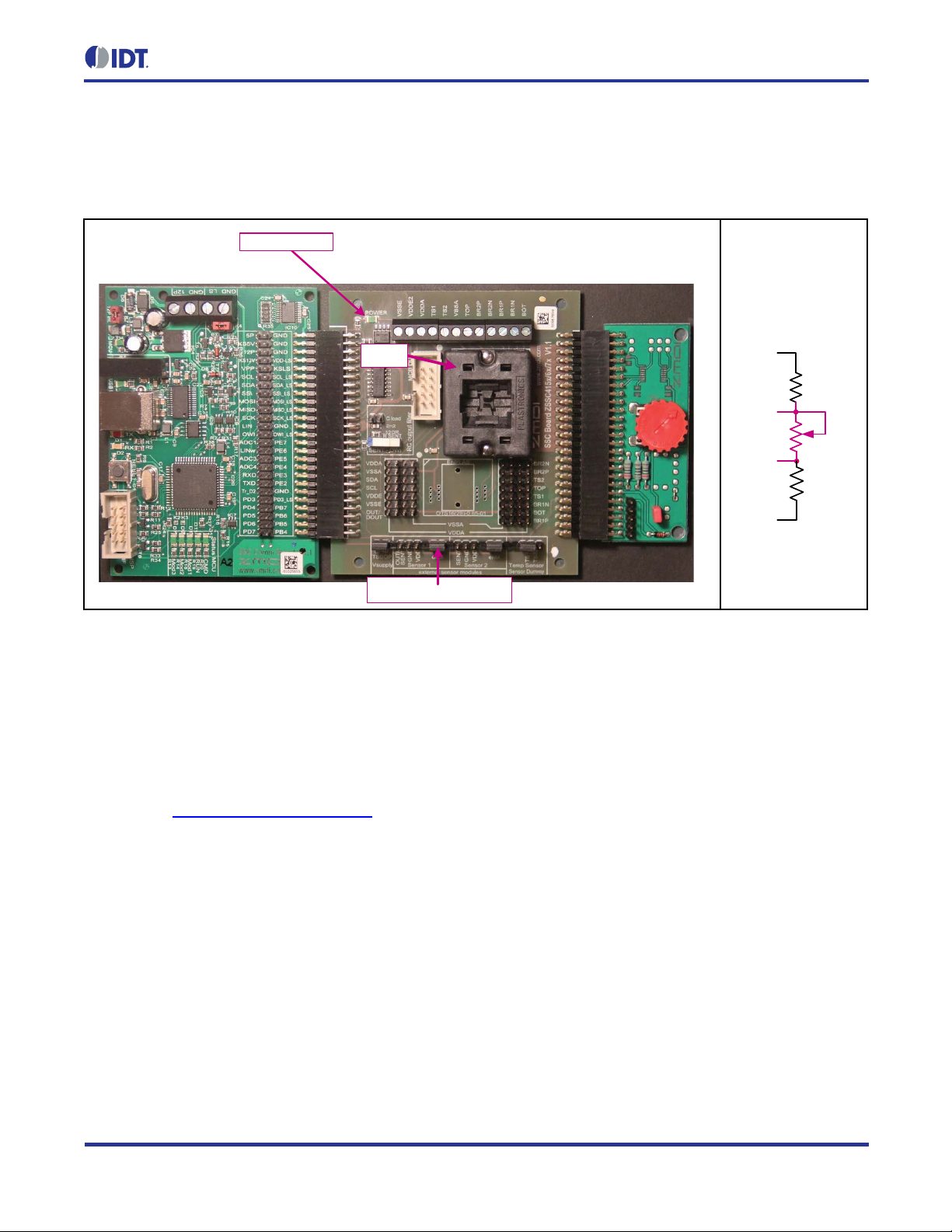
The Evaluation Kit hardware cons ists of th e follo wing three boar ds as sho wn in Figure 2.1 and includes samples
of the ZSSC4151 (QFN24):
2
1. SSC Communication Board – Connects to com puter through a USB 2.0 cable and handles the I
(trademark of NXP) and OWI interfaces between the PC-based software and the ZSSC4151.
2. ZSSC415x/6x/7x Evaluation Board. This board contains a socket for the ZSSC4151 and convenient
access points for connec tion to instrumentation and e xternal sensor circuitr y. Note the location of pin 1
for the QFN24 socket. Jumpers should be installed initially as shown in Figure 2.1.
3. Sensor Replacement Board – See equivalent circuit in Figure 2.1. This bo ard pr ovides a s im ulated input
signal for easy evaluation of functionality without an actual bridge or stimulus. It should be removed
when connecting an external sensor bridge (through screw terminals on Evaluation Board).
C™
*
For detailed information about SSC Communication Board, please refer to the SSC Communication Board Data Sheet available on the IDT websi te at
http://www.IDT.com/ZSSC415xKIT
.
Page 4
Up Guide
© 2016 Integrated Device Technology, Inc. 4 March 11, 2016
SSC Communication Board ZSSC415x/6x/7x Evaluation Board
SSC Sensor
Replacement Board
K1 Power Enable Jumper
Pin 1
Power Indicator
2KΩ
2KΩ
100Ω
TOP
BOT
BR1P
BR1N
SSC Sensor
Replacement Board
Equivalent Circuit
Figure 2.1 ZSSC4151 SSC Evaluation Kit Assembly
ZSSC4151Evaluation Kit Start-
With the three boards assem bled as shown in Figure 2.1, attac h the USB cable included in the kit betwe en the
SSC Comm unication Board and a USB port on a PC. In some cases, t he user’s operating system detects the
board type and autom atically ins talls a driver the first time that the SSC Comm unication Boar d is connect ed. For
this reason, the PC should be connected to the Internet during the first USB connection so that the operating
system can download a driver. If a driver fails to install, contact IDT for assistance.
2.2. Software Setup
The ZSSC4151 Application Software provides a user-friendly graphical user interface (GUI). It is available for
download at www.IDT.com/ZSSC415xKIT
Run the ZSSC415xSetup.exe file from the unzipped location to install the GUI. Launch the ZSSC415x program
from the Start Menu in Windows or by clicking the desktop icon created by the installation program.
To enable resizing the window, go to “SETTINGS” on the top menu and check the “No limits on resizing” as
shown in Figure 2.2.
. After downloading the software, extract the zip file contents.
Page 5

Up Guide
© 2016 Integrated Device Technology, Inc. 5 March 11, 2016
2
1
Figure 2.2 Enabling Resizing Window
2.3. Activating the Hardware Connection
ZSSC4151Evaluation Kit Start-
1. Select I2C™ or OWI (One Wire Interface) from the drop-down menu below “Protocol” (see Figure 2.3).
2. Click the “Connect” button. On the Evaluation Board, verify that the green LED power indicator turns on.
The “ACTIVE DEVICES” list on the right side of the “Main” tab menu shows information about the board
and device that are connected.
Figure 2.3 Connecting the Hardware via I
2
C™ or OWI
Page 6

ZSSC4151Evaluation Kit Start-
Up Guide
© 2016 Integrated Device Technology, Inc. 6 March 11, 2016
1
3
2
2.4. Creating and Loading the Default Configuration File
1. On the top menu, select FILE > Load GUI Configuration to load a configuration file (Figure 2.4).
2. A default configuration file, ZSSC4151.cfgx, is provided with the software as shown in the “File name”
field in Figure 2.4. If necessary, browse to the file location and click the “Open” button.
3. In the resulting “Load GUI Configuration” window, click the “Yes” button to accept overwriting the current
configuration settings.
Figure 2.4 Loading the GUI Configuration File
Page 7

ZSSC4151Evaluation Kit Start-
Up Guide
© 2016 Integrated Device Technology, Inc. 7 March 11, 2016
1
3
2
1
2.5. Loading the NVM Dump File
1. On the top menu, select FILE > Load NVM Dump to load a file containing the NVM data (see Figure 2.5).
2. A default NVM file, zssc4151_nvm.dmpx, is provided with the software as shown in the “File name” field
in Figure 2.5. Browse to the file location, and click the “Open” button.
3. In the resulting “Load RAM Dump” window, click the “Yes” button to accept overwriting current data.
Figure 2.5 Load the NVM Data into GUI
2.6. Writ ing the Memory Contents to NVM
1. Click the “Write All To NVM” button to download the NVM data into the ZSSC4151 (see Figure 2.6).
Figure 2.6 Writing the Configuration into the ZSSC4151 NVM
Page 8

ZSSC4151Evaluation Kit Start-
Up Guide
© 2016 Integrated Device Technology, Inc. 8 March 11, 2016
2
1
2.7. Taking Measurements
Note: The GUI ref ers to the bridg e sensor m easurand as “ Pressure,” b ut this ca n be any t ype of resist ive sensor
signal. The ZSSC4151 is designed for almost all types of resistive full and half bridge sensors.
1. Click the “Start” button to begin acquiring and recording measurements (see Figure 2.7).
2. With the “Pressure” selected in the “Measurements” pulldown, turn the red knob on the Sensor
Replacement Board (Figure 2.1). The “Pressure” (Green) waveform plot should move up and down with
the knob rotation. The “Temperature” and “Pres sur e Ra w” waveforms can also be displayed using the
“Measurements” pulldown selector, but only one waveform at a time will be displayed.
3. Click the “Stop” button to discontinue measurements.
Figure 2.7 Starting and Monitoring the Measurement Sequence
Page 9

ZSSC4151Evaluation Kit Start-
Up Guide
© 2016 Integrated Device Technology, Inc. 9 March 11, 2016
3
2
1
3 Performing a Sample Calibration
This section descr ibes the basic operat ions to perform a sim ple, two-point linea r calibration at a sing le temperature. Higher order calibrations are perf ormed s im ilarly, but with a dditio nal po ints ta ken over the bridg e m easurand
and temperature.
3.1. Setting up the Calibration and Acquiring Data
1. Select the “Calibration” tab to display the “Calibration” window (see Figure 3.1).
2. Ensure that the “Calibration Type Settings” and “Acquisition Settings” are set as shown in Figure 3.1. The
“Calibration Table” shows that there are only two points required to complete the calibration in this case.
3. Set the upper and lower “Target” limits to 90% and 10%. DO NOT change the “Tgt.Min” and “Tgt.Max”
fields.
Figure 3.1 Using the Calibration Window Tab to Set Upper and Lower Target Limits
Page 10

ZSSC4151Evaluation Kit Start-
Up Guide
© 2016 Integrated Device Technology, Inc.
10
March 11, 2016
7
6
5
4
4. Turn the red knob on the Sensor Replacement Board fully counterclockwise. Select the “P1” field and
click the “Acquire Data” button (see Figure 3.2).
5. Turn the red knob on the Sensor Replacement Board fully clockwise. Select the “P2” field and click the
“Acquire Data” button.
6. Click the Calculate button. The coefficients for the calibration will be calibrated and updated in the
calibration formula textbox at the bottom of the window. HINT: Scroll to the bottom of the textbox so that
the “Output” button appears. Move the cursor over the “Output” button. A popup window will appear
showing the complete set of calibration coefficients.
7. Click the “Write Coefficients To NVM” button. This will download the updated coefficients to the NVM of
the ZSSC4151.
Figure 3.2 Using the Calibration Window Tab to Acquire Data and Calculate Coefficients
Page 11

ZSSC4151Evaluation Kit Start-
Up Guide
© 2016 Integrated Device Technology, Inc.
11
March 11, 2016
3.2. Checking the Calibration
The calibration can be checked in the “Main” tab.
1. Click the “Start” button in this window and observe the reading to verify readings. If the red knob of the
Sensor Replacement Board has been left in the fully clockwise posit ion as in step 5 in section 3.1, the
calibration at the “P2” calibration point can be verified by checking that the output for “Pressure” is 90%.
2. Similarly, if the red knob is turned fully counterclockwise, the reading should be 10%.
3.3. Saving the NVM Data and GUI Configuration Settings
The GUI settings and NVM contents for this example can be saved to new configuration and NVM dump files.
Select FILE > Save GUI Configuration from the top menu, and save the configuration under a new name. In a
similar way, the NVM dump file can be saved using FILE > Save NVM Dump and creating a new name.
4 Related Documents and Tools
4.1. IDT Related Documents and Tools
Document
ZSSC4151 Data Sheet
ZSSC4151 Feature Sheet
ZSSC415x Graphical User Interface Operation Manual
ZSSC4151 SSC Evaluation Kit Hardware Manual
Visit www.IDT.com/ZSSC4151 and www.IDT.com/ZSSC415xKIT or contact your near est sales office for the lat est
version of these documents.
5 Glossary
Term Description
DUT Device Under Test
GUI Graphical User Interface
NVM Nonvolatile Memory
OWI One-Wire Interface
SSC Sensor Signal Conditioner
USB Universal Serial Bus
Page 12

Up Guide
© 2016 Integrated Device Technology, Inc.
12
March 11, 2016
Corporate Headquarters
www.IDT.com
Sales
www.IDT.com/go/sales
Tech Support
Device Technology, Inc. All rights reserved.
6 Document Revision Hi story
Revision Date Description
1.00 September 14, 2015 First release.
March 11, 2016 Changed to IDT branding.
ZSSC4151Evaluation Kit Start-
6024 Silver Creek Valley Road
San Jose, CA 95138
DISCLAIMER Integrated Device Technol ogy , Inc. (IDT) reserves the right to modi fy the product s and/ or speci fications des cribed herein at any time, without notice, at IDT's sole discretion. Performance
specifications and operating parameters of the described products are determined in an independent state and are not guaranteed to perform the sam e way wh en inst alled in customer products. The
information contained herein is provided without representation or warranty of any kind, whether ex pr ess or impli ed, including, but not limited to, the suitability of IDT's products for any particul ar purpose, an
implied warranty of merchantability, or non-infringement of the intellec tual property rights of others . This document is present ed onl y as a guide and do es not convey any license under i ntellect ual property
rights of IDT or any third parties.
IDT's products are not intended for use in applications involving extreme environmental c onditions or in life support systems or similar devices where the failure or malfunction of an IDT product can be
reasonably expected to significantly affect the health or safety of users. Anyone using an IDT product in such a mann er does s o at their own risk, absent an express, written agreement by IDT.
Integrated Device Technology, IDT and the IDT logo are trademarks or registered tradem ark s of IDT and its subsi diaries in the United S tates and other countries. Other trademarks used herein are the
property of IDT or their respective third party owners. For datasheet type definitions and a glossary of common t erms, visit www.idt.com/go/glossary
1-800-345-7015 or 408-284-8200
Fax: 408-284-2775
www.IDT.com/go/support
. All contents of this document are copyright of Integrated
 Loading...