

Page 1
ZNRG2061 Evaluation Kit User Manual
© 2017 Integrated Device Technology, Inc. 1 March 29, 2017
Description
The ZNRG2061 Evaluation Kit is designed to help the user
evaluate IDT’s ZNRG2061 Smart Photovoltaic DC Arc-Fault
Detector IC. The kit includes the ZNRG2061 Evaluation Board
with a sample ZNRG2061 mounted, a current transformer, and a
micro-USB cable for connecting the kit to the user’s computer.
When the Evaluation Board is connected to the user’s computer
via a USB port, the ZNRG2061 can be monitored for arc-fault
detection. A test arc circuit enables self-testing of the device.
IDT’s ZNRG2061 Arc Analyzer Software provides a graphical
user interface (GUI) to enable configuration, data analysis, and
communication with the ZNRG2061 mounted on the Evaluation
Board. The GUI is also used to activate the training sequence that
allows the ZNRG2061 to adapt its algorithms for safe and reliable
detection of arc faults The GUI is available for download on IDT’s
website.
Features
Complete system demonstrates ZNRG2061 arc-detection
performance
Evaluation Board includes arc test circuitry
Current transformer is included for easy evaluation
The kit can derive its power from the USB connection so no
additional power supply is required
To ensure use of the latest version, the ZNRG2061 Evaluation
Software and the ZNRG2061 Evaluation Software User Guide
are available for download on www.IDT.com/ZNRG2061-EVK
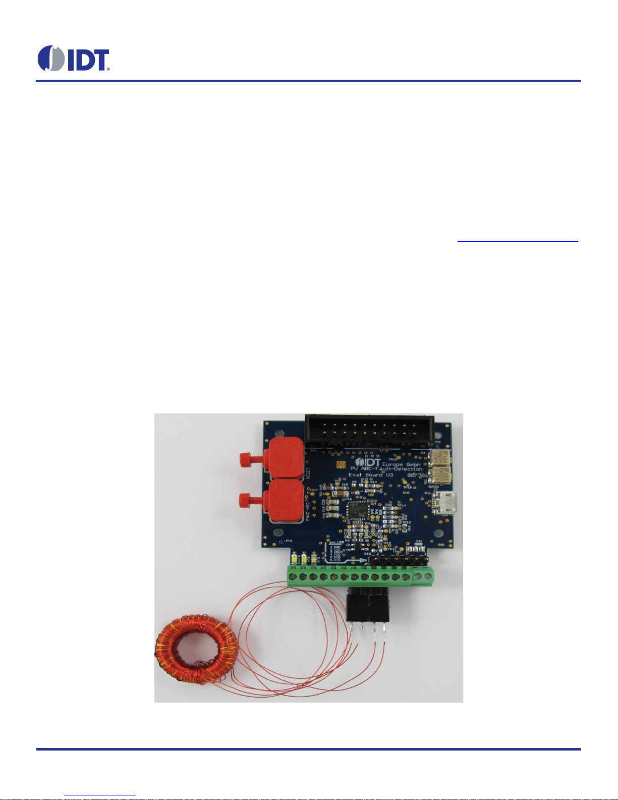
Kit Contents
ZNRG2061 Evaluation Board, Revision V 3.0
100:100-Turns Current Transformer
Micro-USB cable
ZNRG2061 Evaluation Kit
Page 2
ZNRG2061 Evaluation Kit User Manual
© 2017 Integrated Device Technology, Inc. 2 March 29, 2017
Important Notes
Disclaimer
Integrated Device Technology, Inc. and its affiliated companies (herein referred to as “IDT”) shall not be liable for any damages arising out of defects resulting
from
(i) delivered hardware or software
(ii) non-observance of instructions contained in this manual and in any other documentation provided to user, or
(iii) misuse, abuse, use under abnormal conditions, or alteration by anyone other than IDT.
TO THE EXTENT PERMITTED BY LAW, IDT HEREBY EXPRESSLY DISCLAIMS AND USER EXPRESSLY WAIVES ANY AND ALL WARRANTIES,
WHETHER EXPRESS, IMPLIED, OR STATUTORY, INCLUDING, WITHOUT LIMITATION, IMPLIED WARRANTIES OF MERCHANTABILITY AND OF
FITNESS FOR A PARTICULAR PURPOSE, STATUTORY WARRANTY OF NON-INFRINGEMENT, AND ANY OTHER WARRANTY THAT MAY ARISE BY
REASON OF USAGE OF TRADE, CUSTOM, OR COURSE OF DEALING.
Restrictions in Use
IDT’s ZNRG2061 Evaluation Kit consisting of the ZNRG2061 Evaluation Board, 100:100 turns Current Transformer, and micro-USB cable, and the ZNRG2061
Evaluation Software are designed for demonstration and evaluation only. IDT’s ZNRG2061 Evaluation Kit and Evaluation Software must not be used for
performance and characterization purposes.
Important Safety Warning: These procedures can result in high currents, which can cause severe injury or death
and/or equipment damage. Only trained professional staff should connect external equipment and operate the
software.
Important Equipment Warning: Ensure the correct connection of all cables. Supplying the board using the wrong
polarity could result in damage to the board and/or the equipment. Check that all jumpers have been removed from
the board before applying power.
Page 3

ZNRG2061 Evaluation Kit User Manual
© 2017 Integrated Device Technology, Inc. 3 March 29, 2017
1. Set up
1.1 User Equipment
The following additional equipment is required for using the kit:
User’s computer (see requirements in section 1.2).
The following additional lab equipment is optional, but not necessary for the kit functionalities:
Optional external power supply. The USB interface provides a +5V power supply to the Evaluation Board, from which an on-board voltage
regulator can provide 3.3V supply. Alternatively, the ZNRG2061 can be powered by the user’s external power supply (6V to 18V)
connected to VIN + (X1-2) and GND (X1-2) as described in Table 1 (the rest of the Evaluation Board requires the 5V coming from the
USB).
Note: The USB port only supports USB 2.0; USB 3.0 is not supported at this time.
1.2 User Computer Requirements and Setup
A Windows®-based computer is required for interfacing with the kit and configuring the ZNRG2061.
1.2.1 Computer Requirements
The user must have administrative rights on the computer to download and install the ZNRG2061 Arc Analyzer Software for the kit.
The computer must meet the following requirements:
Windows® XP, 7, or 10
Supported architecture: x86 and x64
Available USB port
Internet access for downloading the ZNRG2061 Arc Analyzer Software.
1.2.2 Software Installation and Setup
To ensure use of the latest version of the software, the ZNRG2061 Arc Analyzer Software zip file is available for download in zip file format at
no cost from the IDT web site page given on page 1. It is not included with the kit hardware.
Follow these procedures to install the ZNRG2061 Arc Analyzer Software zip file:
1. After downloading the zip file to the user’s computer, extract the contents of the zip file.
2. Double-click on the extracted setup.exe file to activate the installation.
3. Follow the standard installation instructions displayed on the screen and change the installation path if required. If the default path
settings have been used, the software automatically completes the installation and creates an access link on the user’s computer under
Start > All Programs > IDT. The installation dialog offers the option to create a desktop short-cut icon for the software.
Page 4
ZNRG2061 Evaluation Kit User Manual
© 2017 Integrated Device Technology, Inc. 4 March 29, 2017
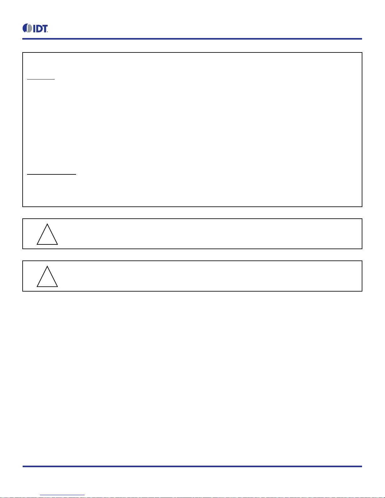
Figure 1. Initial Display after Installation of the Evaluation Software
Note: This is the display when the software is activated for the first time with the kit hardware connected. Refer to the ZNRG2061 Software
User Manual for the initial setup steps for the software.
Page 5
ZNRG2061 Evaluation Kit User Manual
© 2017 Integrated Device Technology, Inc. 5 March 29, 2017
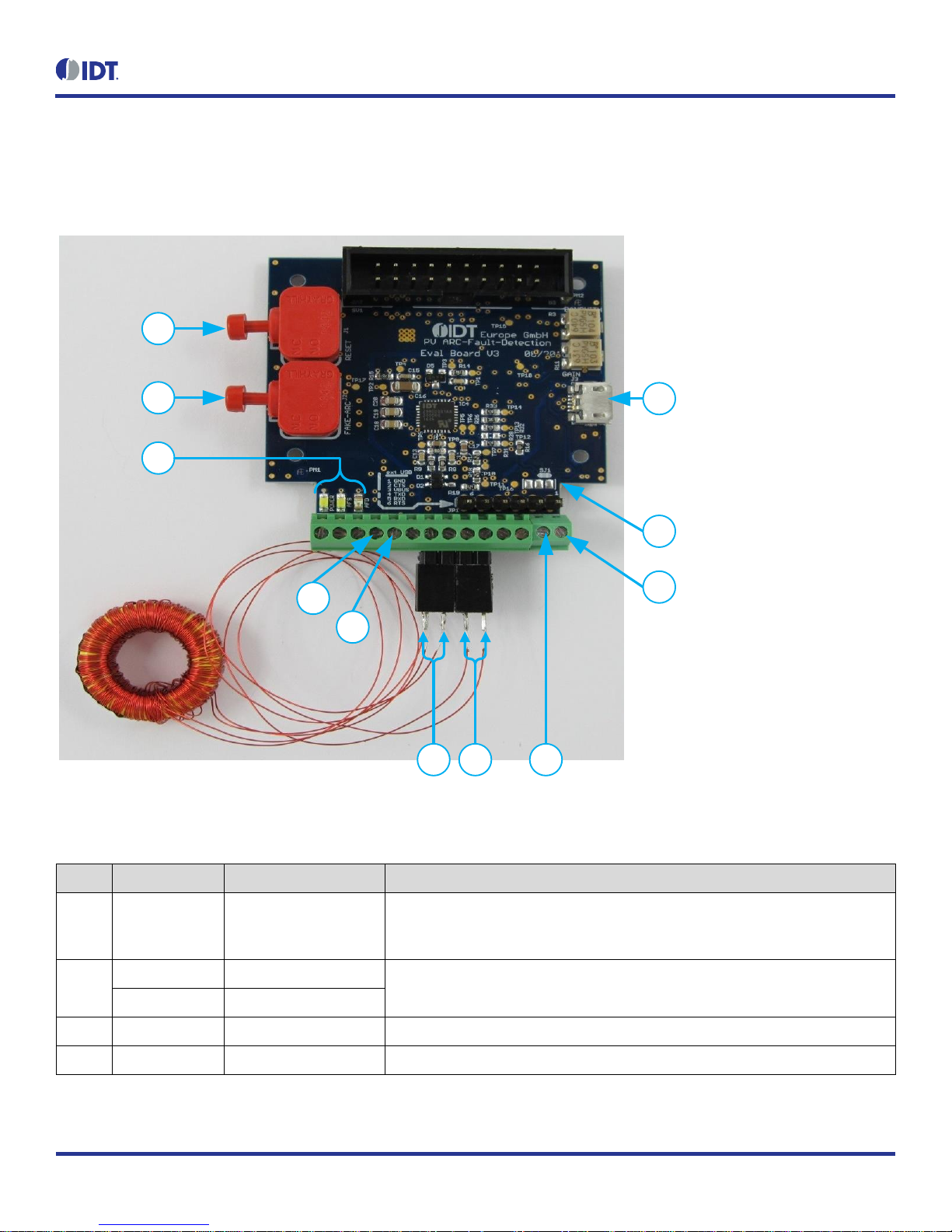
1.3 Kit Hardware Connections
Set up the Evaluation Kit connections as shown in Figure 2. Refer to Table 1 below for the description.
Figure 2. ZNRG2061 Evaluation Board Overview
5
4
6
3
1
7
2 8
9
10
11
Table 1. Evaluation Board Key Components and Functions
Note: See Figure 2 for the number references used in this table. Also see the schematics in section 3.
Ref.
Name
Connector Label
Function
1
USB Connector
J3
This connector is used to connect the Evaluation Board to the user’s computer via
the micro-USB cable. Wait until the instructions in section 1.4 to make this
connection.
2
INP
I+ (X2-7 pin on X2)
Connect INP and INN to the leads for the secondary of the current transformer.
See Figure 4.
INN
I- (X2-8 pin on X2)
3
FAKE-ARC
J2
Pushbutton for Arc Fault Test signal creation.
4
RESET
J1
Pushbutton to reset the ZNRG2061.
Page 6
ZNRG2061 Evaluation Kit User Manual
© 2017 Integrated Device Technology, Inc. 6 March 29, 2017
Ref.
Name
Connector Label
Function
5
AFD
AFD (X2-5 on X2)
Arc-fault detection output. It is indicated by the AFD LED on board. See Figure 4.
6
AFS
AFS (X2-4 on X2)
Arc feature signal output; it is indicated by the AFS LED on board. See Figure 4.
7
Jumper
SJ1
Connection to Arc Fault Test circuitry. See section 2.2.
8
RA+
RA+ (X2-9 pin on X2)
Connect RA+ and RA- to the leads for the primary of current transformer. See
Figure 4.
RA-
RA- (X2-10 pin on X2)
9
VIN+
VIN+
External power supply connector (X1-2).
10
GND
GND
GND pin when using external power supply (X1-1).
11
LEDs
POWER LED
See section 1.4.
AFS LED
See reference 6 above.
AFD LED
See reference 5 above.
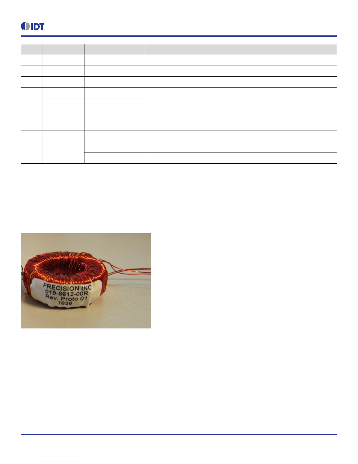
Figure 4 shows pin assignments for the terminal blocks on the Evaluation Board and the details of the connections to the current transformer.
The current transformer included in the kit has 100 turns for both the secondary and auxiliary windings on a T80-26 toroidal core that is
available from Micrometals or KDM. Figure 3 shows a picture of the transformer. Additional transformers can be ordered from Precision, Inc.
at 1700 Freeway Blvd, Brooklyn Center, MN 55430 (http://www.precision-inc.com/).
The RA+/RA- signals are output by the arc test circuitry on the Evaluation Board to the coil.
Figure 3. 100:100-Turns Current Transformer
Page 7

ZNRG2061 Evaluation Kit User Manual
© 2017 Integrated Device Technology, Inc. 7 March 29, 2017
1.4 Power-up
After installing the GUI as described in section 1.2.2 and setting up the kit hardware as described in section1.3, use the micro-USB cable to
connect the USB connector to an available USB port on the user’s computer as shown in Figure 4. Then activate the GUI to control the
Evaluation Board.
Note: When the Evaluation Board has power, the POWER LED will be on (see Figure 2).
Figure 4. Evaluation Board Connections to Current Transformer and User’s Computer
USB
X2 Connector
X1 Connector
100:100
* The asterisk indicates pin 1.
*
*
Page 8

ZNRG2061 Evaluation Kit User Manual
© 2017 Integrated Device Technology, Inc. 8 March 29, 2017
2. Usage Guide
Refer to the ZNRG2061 Software User Manual for full details for using the software.
2.1 Monitoring Output Signals
The outputs signals ADF and AFS are used by the system to monitor the status of the arc detection. They are available on the Evaluation
Board (see Table 1 for the pin locations). Figure 5 shows the possible states for the output signals.
Figure 5. AFD and AFS State Diagram
2.1.1 AFD – Arc Fault Detector
The AFD pin is static, and it can be used to control a DC break switch directly in the event of detecting an arc. If an arc is detected, the AFD
output level goes HIGH.
If the ZNRG2061’s built-in self-test (BIST) detects a malfunction, the AFD pin will be set HIGH. In the event of a malfunction, the ZNRG2061
might attempt to recover automatically. If the final recovery attempt is not successful, the AFD pin will be set HIGH.
If set, the AFD pin is permanently latched HIGH, and the ZNRG2061 will not reset the output by itself. Only a power off/on cycle or a GUI
command can reset this pin.
The red AFD LED indicator on the Evaluation Board (see Figure 2) is on if the AFD pin is set HIGH; otherwise it is not on.
2.1.2 AFS – Arc Feature Signal
The AFS pin is dynamic, and it outputs a signal similar to pulse width modulation (PWM). The information on this pin is defined by the width of
the positive pulse width in milliseconds.
This pin can be used for the following purposes:
The AFS pin can serve as secondary validation pin. This can be implemented on a system level. The AFS pin is designed to be
complementary (dynamic vs. static) to the AFD pin, so that there is an opportunity for detecting a complete component failure.
The AFS output can be used to indicate an error condition as part of its normal functions. It will stop its PWM-like pulses if a malfunction is
detected. A small external circuit (for example, a watchdog circuit) can be used to display the state on the LED.
Example: In the unlikely case of a ZNRG2061 malfunction during an arcing event, the AFD might not be triggered. In this case, the AFS pin
will remain static HIGH or LOW (PWM 0% or 100%), thus indicating the error.
The AFS pin is connected to the white AFS LED indicator which reflects the PWM signal.
Page 9

ZNRG2061 Evaluation Kit User Manual
© 2017 Integrated Device Technology, Inc. 9 March 29, 2017
2.2 Arc Test Circuitry
The Evaluation Board also provides an arc test circuit that can produce a signal to mimic an arcing event. The arc test circuit (see Figure 6)
produces a noise signal that can be controlled manually with a switch.
When the current transformer is connected as shown in Figure 4, the user can press the FAKE-ARC switch, J2, to generate a noise signal via
the transistor Q1 and the IC3 operational amplifier, simulating an arcing event. Pins 1 and 2 on the 3-pin jumper SJ1 must be shorted for the
arc test circuitry to work. The RA+ and RA- must be connected to the secondary of the current transformer per Figure 2.
Potentiometers R3 and R11 (see Figure 7) can be used to adjust the arc test signal. R3 will adjust the op amp gain to obtain the right
amplitude for the test signal. The Evaluation Kit has been pre-tested with the right values for potentiometers R3 and R11.
Refer to the ZNRG2061 Software User Manual for full details for using the arc fault detector test circuit with the GUI.
Figure 6. Arc Test Circuitry Schematic
Figure 7. Potentiometers R3 and R11
R3 Potentiometer
R11 Potentiometer
Page 10

ZNRG2061 Evaluation Kit User Manual
© 2017 Integrated Device Technology, Inc.
10
March 29, 2017
3. Evaluation Board Schematic
Figure 8. Evaluation Board – Main Circuit
Page 11

ZNRG2061 Evaluation Kit User Manual
© 2017 Integrated Device Technology, Inc.
11
March 29, 2017
Figure 9. Evaluation Board Schematic – USB Circuit
Page 12

ZNRG2061 Evaluation Kit User Manual
© 2017 Integrated Device Technology, Inc.
12
March 29, 2017
4. Bill of Materials (BOM)
The parts with an (*) are not populated.
Table 2. Evaluation Board BOM
No
Name
Value
Package
Manufacturer
Qty
1
AFD
KP-2012SURC
0805
Kingbright
1
2
AFS, POWER
LTW-170ZDC
0805
Lite-On
2
3
C1, C2, C4, C5, C6*, C15, C23, C24,
C25
100nF/50V
0603
AVX
8
4
C3*, C20
10nF/100V
0805
AVX 1 5
C7, C8, C16
10µF/25V
1206
AVX
3
6
C9, C12
100µF/10V
1206
TDK
2
7
C10
1nF/100V
0603
AVX 1 8
C11, C13
680pF/50V
0603
Multicomp
2
9
C14
22nF/50V
0603
AVX 1 10
C17
680nF/50V
0603
TDK 1 11
C18, C19
2µ2F/25V
0805
AVX 2 12
C21
220pF/100V
0603
AVX
1
13
C22
2µ2F/16V
0603
AVX
1
14
D1, D2
BAT60J
SOD323
STMicro
2
15
D3, D4, D7
PMEG3010ER
SOD123
NXP 3 16
D5, D6*
PESD1
SOT23
NXP 1 17
IC1
LM317
SOT89-3
TI 1 18
IC2*
LM317
SOT223
TI 0 19
IC3
LM386M-1
SOIC8
TI
1
20
IC4
ZNRG2061
PQFN32 5x5mm
IDT
1
21
J1, J2
39-261-RED
Grayhill
2
22
J3
USB-MICRO
AMP FCI
1
23
JP1
961106-6404-AR
3M 1 24
L1
MH2029-300Y
0805
Bourns
1
25
Q1
MMBT3904
SOT23
ON Semi
1
26
Q2, Q3
BSS138
SOT23
NXP
2
27
R1, R26, R28*, R35, R38, R41, R44
10k
0603
Yageo
6
28
R2
15k
0603
Yageo
1
29
R3
100k
Bourns
1
Page 13

ZNRG2061 Evaluation Kit User Manual
© 2017 Integrated Device Technology, Inc.
13
March 29, 2017
No
Name
Value
Package
Manufacturer
Qty
30
R4
1k1
0603
Yageo
1
31
R5
1k8
0603
Yageo
1
32
R6
1k5
0603
Yageo
1
33
R7, R40
2k2
0603
Yageo
2
34
R8, R9, R20, R21, R22, R23, R24,
R42, R43
33R
0603
Yageo
9
35
R10, R36, R37
1k
0603
Yageo
3
36
R11
10k Bourns
1
37
R12, R13
10R
0603
Yageo
2
38
R14, R15
2R2
0603
Yageo
2
39
R16
1k2
0603
Yageo
1
40
R17, R18, R19
120k
0603
Yageo
3
41
R25, R27, R29, R30, R34, R46
4k7
0603
Yageo
6
42
R31, R32, R33
47R
0603
Yageo
3
43
R39
380R
0603
Yageo
1
44
R45
0R
0603
Yageo
1
45
R47, R48
470R
0603
Yageo
2
46
SV1
75869-104LF
AMP FCI
1
47
U1
FT232RQ
QFN32
FTDI
1
48
X1
1725656
Phoenix Contact
1
49
X2
1725753
Phoenix Contact
2
50
Z1, Z2
CG0603MLC-05E
0603
Bourns
2
Page 14

ZNRG2061 Evaluation Kit User Manual
© 2017 Integrated Device Technology, Inc.
14
March 29, 2017
5. Board Layout
Figure 10. ZNRG2061 Evaluation Board V3.0 Board Layout – Top Assembly Layer with Silkscreen
Page 15

ZNRG2061 Evaluation Kit User Manual
© 2017 Integrated Device Technology, Inc.
15
March 29, 2017
Figure 11. ZNRG2061 Evaluation Board V3.0 Board Layout – Top Layer
Page 16

ZNRG2061 Evaluation Kit User Manual
© 2017 Integrated Device Technology, Inc.
16
March 29, 2017
Figure 12. ZNRG2061 Evaluation Board V3.0 Board Layout – Bottom Layer
Page 17

ZNRG2061 Evaluation Kit User Manual
© 2017 Integrated Device Technology, Inc.
17
March 29, 2017
Figure 13. ZNRG2061 Evaluation Board V3.0 Board Layout – Bottom Assembly and Silkscreen
Page 18

ZNRG2061 Evaluation Kit User Manual
© 2017 Integrated Device Technology, Inc.
18
March 29, 2017
6. Ordering Information
Orderable Part Number
Description
ZNRG2061KITV1P0
ZNRG2061 Evaluation Kit, including the ZNRG2061 Evaluation Board, 100:100-Turns Current Transformer,
and a micro-USB cable.
7. Revision History
Revision Date
Description of Change
March 29, 2017
Initial release.
Corporate Headquarters
6024 Silver Creek Valley Road
San Jose, CA 95138
www.IDT.com
Sales
1-800-345-7015 or 408-284-8200
Fax: 408-284-2775
www.IDT.com/go/sales
Tech Support
www.IDT.com/go/support
DISCLAIMER Integrated Device Technology, Inc. (IDT) and its affiliated companies (herein referred to as “IDT”) reserve the right to modify the products and/or specifications described herein at any time,
without notice, at IDT's sole discretion. Performance specifications and operating parameters of the described products are d etermined in an independent state and are not guaranteed to perform the same
way when installed in customer products. The information contained herein is provided without representation or warranty of a ny kind, whether express or implied, including, but not limited to, the suitability
of IDT's products for any particular purpose, an implied warranty of merchantability, or non -infringement of the intellectual property rights of others. This document is presented only as a guide and does not
convey any license under intellectual property r ights of IDT or any third parties.
IDT's products are not intended for use in applications involving extreme environmental conditions or in life support systems or similar devices where the failure or malfunction of an IDT product can be
reasonably expect ed to significantly affect the health or safety of users. Anyone using an IDT product in such a manner does so at their own r isk, absent an express, written agreement by IDT.
Integrated Device Technology, IDT and the IDT logo are trademarks or registered trademarks of IDT and its subsidiaries in the United States and other countries. Other trademarks used herein are the
property of IDT or their respective third party owners. For datasheet type definitions and a glossary of common terms, visit www.idt.com/go/glossary. All contents of this document are copyright of
Integrated Device Technology, Inc. All rights reserved.
 Loading...