

Page 1
ZMOD4510 Evaluation Kit User Manual
© 2019 Integrated Device Technology, Inc. 1 August 14, 2019
Description
The ZMOD4510 Evaluation Kit (EVK) is designed for evaluating
IDT’s ZMOD4510 Gas Sensor Module for Total Outdoor Air Quality
(OAQ). The sensor module is optimized for the detection of trace
atmospheric gases, including nitrogen oxides (NOx) and ozone
(O3) and reporting an Air Quality Index (AQI) based on the standard
of the US Environmental Protection Agency (EPA).
IDT’s Gas Sensor Evaluation Software allows Windows®-based
operating systems to communicate with the ZMOD4510 EVK via a
USB connection on the user’s computer, which functions as a
master. The software and additional related documentation is
available on the IDT website.
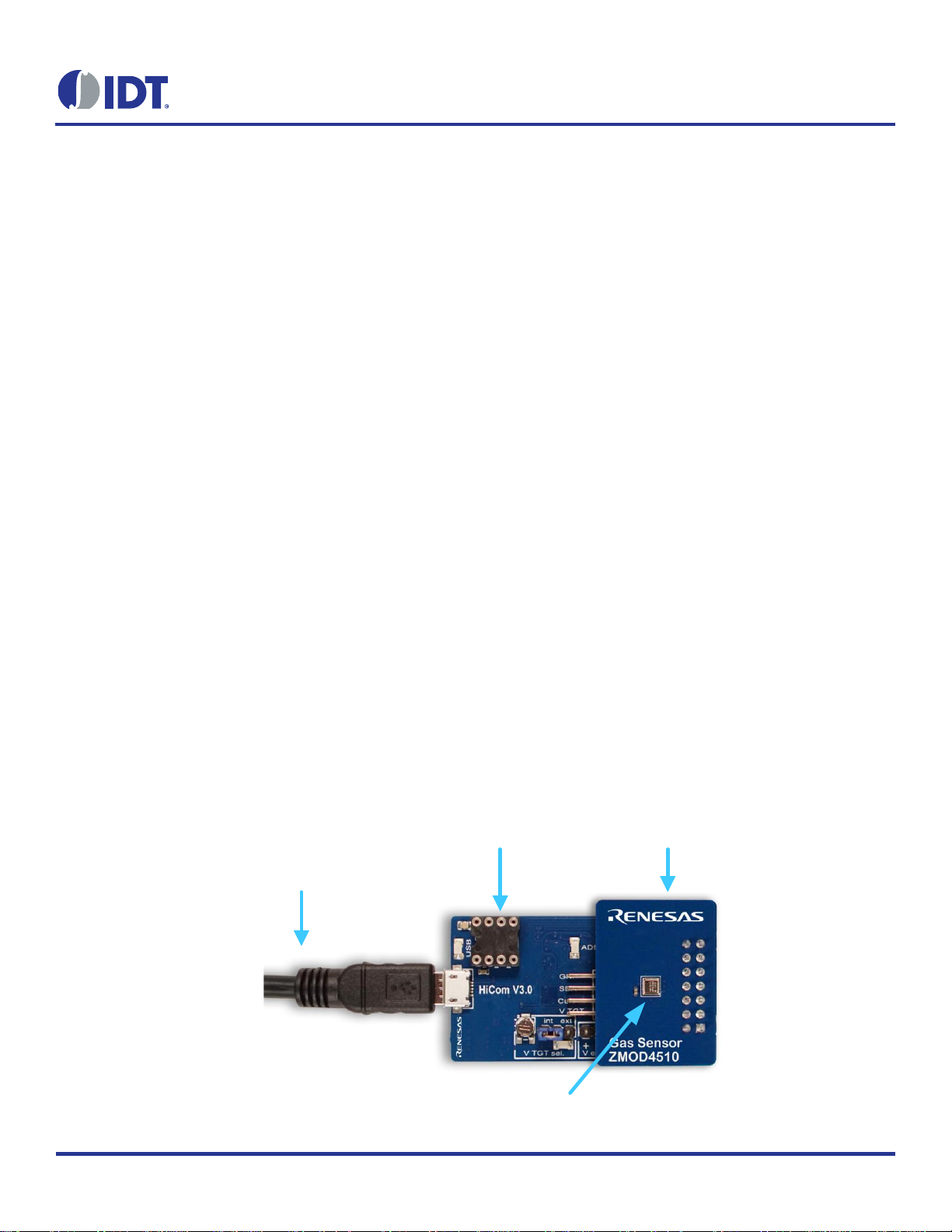
The EVK’s Communication Board (HiCom) handles the interface
between the user’s computer and the ZMOD4510 module mounted
on the ZMOD4510 Sensor Board (i.e., daughter board). Note: Only
one Communication Board with one Sensor Board can be
connected to the computer at a time.
The ZMOD4510 Evaluation Kit uses an FTDI controller on the
Communication Board to handle the USB protocol, translate
communications, and synchronize communications with the I2C
interface. The Sensor Board includes a decoupling capacitor.
The Communication Board has devices mounted on both sides.
The components on the top side generate a stable supply voltage.
A potentiometer can be used to adjust the internal supply voltage
in the typical range from 1.7V to 3.6V. Alternatively, the user’s
external supply voltage can be used. The intensity of the adjacent
LED is proportional to the supply voltage.
ZMOD4510 Evaluation Kit
Features
User-friendly EVK expedites configuration and evaluation of
the ZMOD4510 Total Outdoor Air Quality Sensor
Operates with IDT provided software; either with executable
ZMOD4510 GUI or alternatively with firmware programming
examples for Windows® and Linux®
The modular design of the EVK allows simple connection of
Sensor Boards for different gas sensor derivatives and easy
integration with other sensor products via the I2C interface.
The required Gas Sensor Evaluation Software is available for
free download on the IDT website, which also provides
background information on outdoor air quality and sensor
programming.
Additional pins provided to measure power consumption,
supply voltage, and the GPIO trigger for an external device
The bill of materials (BOM) and schematics for the
ZMOD4510 Communication Board and Sensor Board are
included in this document.
ZMOD4510-EVK Contents
HiCom Communication Board
Sensor Board with ZMOD4510 Gas Sensor Module
3.0m Type-B USB to Micro-USB Cable
USB Cable to Computer
HiCom Communication Board
ZMOD4510
Sensor Board
ZMOD4510
Page 2

ZMOD4510 Evaluation Kit User Manual
© 2019 Integrated Device Technology, Inc. 2 August 14, 2019
Important Notes
Disclaimer
Integrated Device Technology, Inc. and its affiliated companies (herein referred to as “IDT”) shall not be liable for any damages arising out of defects resulting from
(i) delivered hardware or software
(ii) non-observance of instructions contained in this manual and in any other documentation provided to the user, or
(iii) misuse, abuse, use under abnormal conditions, or alteration by anyone other than IDT.
TO THE EXTENT PERMITTED BY LAW, IDT HEREBY EXPRESSLY DISCLAIMS AND USER EXPRESSLY WAIVES ANY AND ALL WARRANTIES, WHETHER
EXPRESS, IMPLIED, OR STATUTORY, INCLUDING, WITHOUT LIMITATION, IMPLIED WARRANTIES OF MERCHANTABILITY AND OF FITNESS FOR A
PARTICULAR PURPOSE, STATUTORY WARRANTY OF NON-INFRINGEMENT, AND ANY OTHER WARRANTY THAT MAY ARISE BY REASON OF USAGE
OF TRADE, CUSTOM, OR COURSE OF DEALING.
Restrictions in Use
IDT’s ZMOD4140 Evaluation Kit, consisting of the HiCom Communication Board, ZMOD4510 Sensor Board, and the ZMOD4510 Evaluation Software, is designed
for evaluation purpose only. IDT’s ZMOD4510 Evaluation Kit must not be used for calibration, test, qualification, production or usage in safety-critical or life-
protecting applications.
Important Equipment Warning: Ensure the correct connection of all cables. Supplying the board using the wrong
polarity could result in damage to the board and/or the equipment. Check that all jumpers have been placed as
specified in this document.
Contents
1. Setup ............................................................................................................................................................................................................4
1.1 Required or Recommended User Equipment ......................................................................................................................................4
1.2 User Computer Requirements .............................................................................................................................................................4
1.2.1 Computer Requirements ......................................................................................................................................................4
1.3 Software Installation and Setup ...........................................................................................................................................................4
1.4 EVK Hardware Connections and Initial Power-up ...............................................................................................................................5
2. Usage Guide .................................................................................................................................................................................................8
2.1 Measurement Control Block ................................................................................................................................................................8
2.2 Signal Analysis Block ..........................................................................................................................................................................9
2.3 Plot Visualization Block .......................................................................................................................................................................9
3. Schematics .................................................................................................................................................................................................10
4. Bill of Materials (BOM) ................................................................................................................................................................................13
5. Board Layout ..............................................................................................................................................................................................15
6. Ordering Information ...................................................................................................................................................................................17
7. Revision History ..........................................................................................................................................................................................17
!
Page 3

ZMOD4510 Evaluation Kit User Manual
© 2019 Integrated Device Technology, Inc. 3 August 14, 2019
List of Figures
Figure 1. Initial Display after Installation of the Gas Sensor Evaluation Software ..............................................................................................5
Figure 2. Jumper Settings, LEDs, and Connectors on Top Side of ZMOD4510 Communication Board ............................................................6
Figure 3. Jumper Settings, Connections, and Test Points on Communication Board for the Internal or External Supply Voltage .....................7
Figure 4. Initial Display for the ZMOD4510 Start-up ...........................................................................................................................................8
Figure 5. Communication Board Schematic – Page 1 ......................................................................................................................................10
Figure 6. Communication Board Schematic – Page 2 ......................................................................................................................................11
Figure 7. Sensor Board Schematic ...................................................................................................................................................................12
Figure 8. HiCom Communication Board Layout – Top Layer ...........................................................................................................................15
Figure 9. HiCom Communication Board Layout – Bottom Layer ......................................................................................................................15
Figure 10. Sensor Board Layout – Top Layer .....................................................................................................................................................16
Figure 11. Sensor Board Layout – Bottom Layer ...............................................................................................................................................16
List of Tables
Table 1. Evaluation Kit Connection Descriptions ...............................................................................................................................................6
Table 2. Signal Analysis Block User Options ....................................................................................................................................................9
Table 3. Communication Board BOM ..............................................................................................................................................................13
Table 4. Sensor Board BOM ...........................................................................................................................................................................15
Page 4

ZMOD4510 Evaluation Kit User Manual
© 2019 Integrated Device Technology, Inc. 4 August 14, 2019
1. Setup
1.1 Required or Recommended User Equipment
By default, the internal supply voltage for powering the Sensor Board is generated from the USB voltage supplied by the user’s computer via
the USB cable. If there is a need for currents higher than the defined USB standard (usually 500mA at 5V), an external voltage supply source
can be used instead of the internally generated voltage supply provided on the Communication Board.
The external supply only powers the sensor modules, and not the communication board itself. The supply must meet the following requirements:
Voltage – 1.7V to 3.6V
Current must meet the user’s specifications – The minimum is 30mA for electronics with additional current needed for each gas sensor
module of approximately 11mA (with a 1.8V voltage supply).
1.2 User Computer Requirements
1.2.1 Computer Requirements
A Windows-based computer is required for interfacing with the EVK and configuring the ZMOD4510. The user must have administrative rights
on the computer to download and install the Gas Sensor Evaluation Software.
The computer must meet the following requirements:
1GB RAM
Hard drive with at least 250MB free space
1 USB port
Windows Vista
®
/Windows 7®/Windows 8®/Windows 10®
Internet access for initial download of the drivers and software
Important: Before installing and activating the software, assemble and connect the hardware for the kit to the user’s computer according to
steps 1 through 3 in “EVK Hardware Connections and Initial Power-up.”
1.3 Software Installation and Setup
Before using the Gas Sensor Evaluation Software, the USB drivers for the FTDI device must be installed. Download the drivers and
corresponding installation guides from the FTDI website (www.ftdichip.com). The drivers will not affect the operation of any other USB
peripherals. The kit does not need to be connected during installation of the drivers.
Complete the following procedure to download and install the ZMOD4510 Evaluation Software with the kit connected:
1. Download the ZMOD4510 Gas Sensor Evaluation Software zip file at www.IDT.com/ZMOD4510-EVK.
2. Create a folder on the user’s computer for the software (e.g., C:\Program Files (x86)\IDT Software). Extract the contents of the
downloaded zip file into this folder.
3. Double-click on the extracted executable file Gas_Sensor_Evaluation.bat to start the software each time the program is used and
select the ZMOD4510 – Outdoor Air Quality option. Figure 1 shows the initial display after execution.
Page 5

ZMOD4510 Evaluation Kit User Manual
© 2019 Integrated Device Technology, Inc. 5 August 14, 2019
Figure 1. Initial Display after Installation of the
Gas Sensor Evaluation
Software
1.4 EVK Hardware Connections and Initial Power-up
To set up the EVK hardware before using the software, complete the following procedure:
1. Refer to Figure 2, Figure 3, and Table 1 to determine the correct jumper settings for the ZMOD4510 Communication Board depending on
whether an external supply or the internal voltage supply on the board is used.
If the internal voltage supply is used, ensure that the jumper is across the pins labeled “int” on the K2 connector.
If using an external supply, ensure that the jumper is across the pins labeled “ext” on the K2 connector. In this case, without
connecting the external supply to the Communication Board, verify that the external voltage supply setting does not exceed the
voltage supply specifications (i.e., a minimum of 1.7V and a maximum of 3.6V) as per the ZMOD4510 Datasheet. With the external
supply off, connect the external voltage to the 2-pin “+ - V ext” header adjacent to the K2 jumper with the orientation indicated in
Figure 3. Note: If this option is used, adjustments of the external voltage are not possible on either the Communication Board or the
Sensor Board for adjusting an external voltage supply.
2. Install the ZMOD4510 Sensor Board on the 14-pin connector on the Communication Board, taking care to ensure the proper orientation
of the Sensor Board as shown on page 1.
3. Insert the micro-USB cable into the X1 connector on the Communication Board and connect it to a free USB port on the user’s computer.
If the external voltage supply has been selected, turn on the external supply and verify that the D3 LED adjacent to the potentiometer is
on (see Figure 2). Note: The intensity of the green D3 LED is proportional to the supply voltage.
4. Activate the software as described in “Software Installation and Setup”.
5. If the internal voltage is used, the Gas Sensor Evaluation Software activates the internal voltage after the sensor has been started. Use
the metal potentiometer to the left of the K2 connector to adjust the VDD supply voltage in the typical range from 1.7V to 3.6V as
measured across the V_TGT and GND pins available on the K3 connector as shown in Figure 3. Its initial adjustment on delivery
provides a voltage of VDD ≈ 2.0V. Once a measurement has been started by the software, the green D3 LED adjacent to K2 will light
with an intensity proportional to the voltage supply that was set using the potentiometer.
6. Verify that the red D1 LED is on, which indicates that the kit is properly connected and powered (see Figure 2).
The Communication Board provides the additional K3 and Modul1 connectors for the following optional uses as described in Table 1. To make
use of any of these options, contact IDT for further instructions (see contact information on last page).
Extra measurement options (e.g., current consumption to determine the power requirements of the ZMOD4510)
Connections for additional sensors (e.g., IDT humidity sensor HS3001)
Page 6
ZMOD4510 Evaluation Kit User Manual
© 2019 Integrated Device Technology, Inc. 6 August 14, 2019
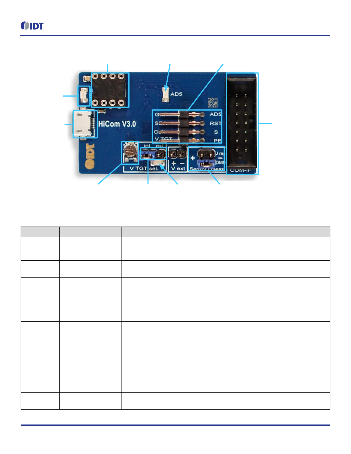
Figure 2. Jumper Settings, LEDs, and Connectors on Top Side of ZMOD4510 Communication Board
Select Internal or
External Supply for
Sensor Board (K2)
Potentiometer for
Setting Supply
Voltage (R19)
Current Measurement
Direct or Shunt Resistor (K1)
14-Pin Connector for
Sensor Board (K4)
8-Pin, 2-Row Connector (K3)
Micro USB B-Type
Connector (X1)
Status LED (D1)
External Sensor Socket (Modul1) AD5 Status LED (D2)
Internal Supply
Status LED (D3)
Table 1. Evaluation Kit Connection Descriptions
Connector
Type
Description
K1
4-pin, 2-row header
This jumper can be used to break the supply voltage line to measure the current consumption of
a connected Sensor Board. Important: During normal operation, ensure that a jumper is on the
“DMM” position as shown in Figure 2.
K2
3-pin header
This jumper selects either the internal or external voltage supply. For the proper position for the
jumper, see Figure 3.
K3
8-pin, 2-row right-angle
header
This connector can be used to connect the ZMOD4510 in different configurations or to measure
the communication lines and voltages on the ZMOD4510 Sensor Board. AD5 is a GPIO pin that
can be controlled via the software.
K4
14-pin connector
This is the connector for installing the ZMOD4510 Sensor Board on the Communication Board.
K5
2-pin header
This is the connector for an optional external voltage supply (see Figure 3).
D1
Status LED
This LED lights if the Communication Board is powered correctly (see Figure 2).
D2/AD5
Status LED
This LED lights if the trigger pin is set by the software (see Figure 2).
D3
Status LED
This LED will light with an intensity proportional to the internal voltage supply that was set using
the potentiometer (see Figure 2).
X1
Micro-USB B-type
This is the micro-USB cable connector for connecting the Communication Board to the user’s
computer.
R19
Potentiometer
This potentiometer adjusts the internal supply voltage. The internal supply voltage can be
adjusted by rotating the potentiometer with a small screwdriver.
Modul1
DIL socket
This socket can be used to add external components (e.g., a humidity sensor) to the
Communication Board. For further instructions, contact IDT.
Page 7

ZMOD4510 Evaluation Kit User Manual
© 2019 Integrated Device Technology, Inc. 7 August 14, 2019
Figure 3. Jumper Settings, Connections, and Test Points on Communication Board for the Internal
or External Supply Voltage
K2 Jumper:
If using the internal supply, set
the jumper to the intposition
If using an external supply, set
the jumper to the extposition
V ext + External Positive Supply K5
V ext – External Negative Supply K5
V_TGT pin on K3 (Bottom)
GND pin on K3 (Bottom)
GPIO (AD5) on K3 (Top)
Page 8

ZMOD4510 Evaluation Kit User Manual
© 2019 Integrated Device Technology, Inc. 8 August 14, 2019
2. Usage Guide
When the Gas Sensor Evaluation Software with the ZMOD4510 – Outdoor Air Quality option is started, the initial window is displayed as shown
in Figure 4.
The initial display consists of three blocks:
Measurement Control
Signal Analysis
Plot Visualization
Figure 4. Initial Display for the ZMOD4510 Start-up
Measurement Control
Signal Analysis
Plot Visualization
2.1 Measurement Control Block
The “Measurement” area of the display allows users to start the ZMOD4510’s gas measurements. When the “start sensor” button is clicked,
the button name changes to “stop sensor” and the measurement starts running continuously with the given sample time (the default is 1 minute).
The results will be saved in a comma separated file (CSV), which is user-selected via the file and path selection dialog when the sensor is
started.
A comment (e.g., “Start test”) can be added to the data entry by adding a text string to the “Add comment to next measurement” field and then
clicking the “ok” button. If a measurement is already in progress, the comment will be added to the next measurement. The comments will be
displayed in the plot and will be saved in the CSV result file. This facilitates tracking the user’s experimental investigations. Below this entry
field, a small window with a log field shows all events logged.
Page 9

ZMOD4510 Evaluation Kit User Manual
© 2019 Integrated Device Technology, Inc. 9 August 14, 2019
2.2 Signal Analysis Block
Table 2. Signal Analysis Block User Options
Display Section
Button/Action
Description
Display
The “clear memory” button will delete all current data from the plots (memory). The data
in the measurement file will remain.
If measurements are acquired simultaneously for multiple ZMOD4510 gas sensors, the
measurement results file can contain data from different sensors. In the “Sensor” dropdown menu, the user can choose a sensor to display by selecting the unique sensor
identification number.
The drop-down menu adjacent to the “show” button provides options for selecting the
time period for showing the recent history or the complete data. Click the “show” button
to apply new settings to the plots.
Algorithm Result
The first 10 measurements of the algorithm will be taken for sensor stabilization. During
this time, the “Algorithm Result” section will indicate the completion progress. Note that
this does not cover the full stabilization of the sensor module. Recommendation: The
ZMOD4510 has a sample time of 1 minute for these 10 measurements resulting in 10
minutes for the initialization measurements.
After the stabilization measurements, the “Air Quality Index” (AQI) is shown in six
categories:
0 to 50 Good Air Quality
51 to 100 Moderate Air Quality
101 to 150 Unhealthy Air Quality for Sensitive Groups
151 to 200 Unhealthy Air Quality
201 to 300 Very Unhealthy Air Quality
> 300 Hazardous Air Quality
2.3 Plot Visualization Block
The lower half of the display provides a visualization of the data. This plot shows the AQI based on the standard of the US Environmental
Protection Agency (EPA). For additional information, including application notes, white papers and blogs, visit www.idt.com/ZMOD4510.
Page 10

ZMOD4510 Evaluation Kit User Manual
© 2019 Integrated Device Technology, Inc.
10
August 14, 2019
3. Schematics
Figure 5. Communication Board Schematic – Page 1
Page 11

ZMOD4510 Evaluation Kit User Manual
© 2019 Integrated Device Technology, Inc.
11
August 14, 2019
Figure 6. Communication Board Schematic – Page 2
Page 12

ZMOD4510 Evaluation Kit User Manual
© 2019 Integrated Device Technology, Inc.
12
August 14, 2019
Figure 7. Sensor Board Schematic
Page 13

ZMOD4510 Evaluation Kit User Manual
© 2019 Integrated Device Technology, Inc.
13
August 14, 2019
4. Bill of Materials (BOM)
Table 3. Communication Board BOM
Position
Name
Value
Package
1
C3
10µF/16V
0805
2
C5
100nF
0603
3
C6
10nF
0805
4
C7
100nF
0603
5
C8
100nF
0603
6
C9
10µF/16V
0805
7
C10
10µF/16V
0805
8
C11
10µF/16V
0805
9
C12
100nF
0603
10
C13
100nF
0603
11
C14
100nF
0603
12
C15
100nF
0603
13
C16
100nF
0603
14
C17
10µF/16V
0805
15
C18
27pF
0603
16
C19
27pF
0603
17
C20
10µF/16V
0805
18
C21
10µF/16V
0805
19
C22
100nF
0603
20
C23
100nF
0603
21
C24
10µF/16V
0805
22
C25
100nF
0603
23
C26
100nF
0603
24
C27
10µF/16V
0805
25
C28
100nF
0603
26
C29
10µF/16V
0805
27
C30
100nF
0603
28
C31
220nF
0805
29
D1
LED 1206RT
1206-DIODE
30
D2
LED 1206GN
1206-DIODE
31
D3
LED 1206GN
1206-DIODE
32
D4
SD0805S040S0R1-SCHOTTKY
0805-DIODE
33
IC1
LP38692-adj
SOT-223-5
Page 14

ZMOD4510 Evaluation Kit User Manual
© 2019 Integrated Device Technology, Inc.
14
August 14, 2019
Position
Name
Value
Package
34
IC2
LP38692-adj
SOT-223-5
35
IC3
93LC46B
SOT23-6
36
IC4
FT2232HL
LQFP64
37
IC6
SN74LVC1T45
SOT23-6
38
IC8
SN74LVC2T45DCT
SSOP8_0,65
39
K1
I_meas
2X02
40
K2
Select
1X03
41
K3
K2X4
2X04-90
42
K4
K2X7
LH-14
43
K5
V_EXT
1X02
44
L1
10µH
1210
45
L2
10µH
1210
46
L3
10µH
1210
47
Modul1
Honeywell480-3652-1-ND
DIL8 SMD Socket
48
Q1
12.00MHz
QUARZ-ABM3
49
R1
1kΩ
0805
50
R2
1kΩ
0805
51
R3
1.6kΩ
0805
52
R4
12kΩ
0805
53
R5
47kΩ
0805
54
R6
2.2kΩ
0805
55
R7
10kΩ
0805
56
R8
1kΩ
0805
57
R13
51Ω
0805
58
R15
51Ω
0805
59
R16
10Ω
0805
60
R17
1kΩ
0805
61
R18
470Ω
0805
62
R19
2.0kΩ
TRIMMER-3142 SERIES
63
R20
1kΩ
0805
64
R21
10kΩ
0805
65
R22
2.0kΩ
0805
66
R23
2.0kΩ
0805
67
X1
USB-micro-B-5pol-SMD-Bu
USB-MICRO_TYPB_AMTEK
Page 15

ZMOD4510 Evaluation Kit User Manual
© 2019 Integrated Device Technology, Inc.
15
August 14, 2019
Table 4. Sensor Board BOM
Designator
Quantity
Manufacturer
Manufacturer Part Number
C1 2 Taiyo Yuden
LMK105BJ104KV-F
U1
1
IDT
ZMOD4510
X1
1
Sullins
SFH11-PBPC-D07-ST-BK
5. Board Layout
Figure 8. HiCom Communication Board Layout – Top Layer
Figure 9. HiCom Communication Board Layout – Bottom Layer
Page 16

ZMOD4510 Evaluation Kit User Manual
© 2019 Integrated Device Technology, Inc.
16
August 14, 2019
Figure 10. Sensor Board Layout – Top Layer
Figure 11. Sensor Board Layout – Bottom Layer
Page 17

ZMOD4510 Evaluation Kit User Manual
© 2019 Integrated Device Technology, Inc.
17
August 14, 2019
6. Ordering Information
Orderable Part Number
Description
ZMOD4510-EVK-HC
ZMOD4510 Evaluation Kit including the ZMOD4510 Sensor Board, HiCom Communication Board (USB Interface)
and Micro-USB Cable. The Gas Sensor Evaluation Software is available for download free of charge on
www.IDT.com/ZMOD4510-EVK
7. Revision History
Revision Date
Description of Change
August 14, 2019
Initial release.
Corporate Headquarters
6024 Silver Creek Valley Road
San Jose, CA 95138
www.IDT.com
Sales
1-800-345-7015 or 408-284-8200
Fax: 408-284-2775
www.IDT.com/go/sales
Tech Support
www.IDT.com/go/support
DISCLAIMER Integrated Devic e Technology, Inc. (IDT) and its affiliated companies (herein referred to as “IDT”) reserve the right to modify the products and/or specifications described herein at an y time,
without notice, at IDT's sole discretion. Performanc e specifications and operating parameters of the described products ar e determined in an independent s tate and are not guarantee d to perform the same
way when installed in customer products . The information contained herein is provided without repres entation or warranty of a ny kind, whether express or implied, including, but not limited to, the suitability
of IDT's products for any particular purpose, an implied warranty of merchantability, or non-infringem ent of the intellectual property rights of others. This document is presented only as a guide and does not
convey any license under intellectual property rights of IDT or any third parties.
IDT's products are not i ntended for use in applicati ons involving extreme environmental conditions or in life support systems or similar devices where the failure or malfunction of an IDT product can be
reasonably expected to significantly affect the health or safety of users. Anyone using an IDT product in such a mann er does so at their own risk, absent an express, written agreement by IDT.
Integrated Device Technology, IDT and the IDT logo are trademarks or registered trademarks of IDT and its subsidiaries in the United States and other countries. Other tr ademarks used herei n are the
property of IDT or their respective third party owners. For datasheet type definitions and a glossary of common terms, visit www.idt.com/go/glossary. All contents of this document are copyright of Integrated
Device Technology, Inc. All rights reserved.
 Loading...