

Page 1
ZMID520x Evaluation Kit User Manual
© 2018 Integrated Device Technology, Inc.
1
September 25, 2018
Description
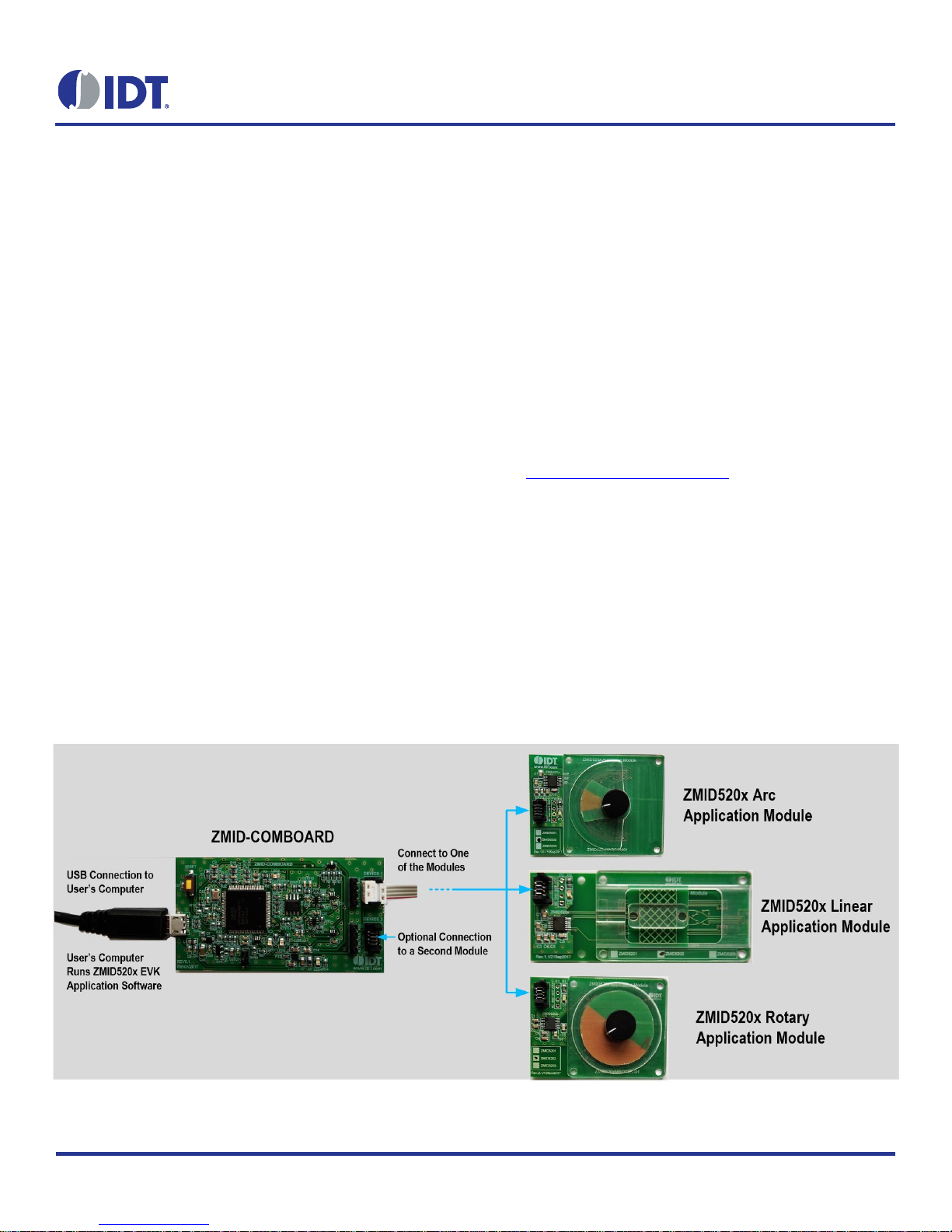
The ZMID520x Evaluation Kit enables evaluation of the IDT
ZMID520x Family of Inductive Position Sensor ICs via IDT’s
ZMID520x Application Modules (available separately). It can be
used for the sensor calibration for the following ICs:
ZMID5201: analog interface
ZMID5202: PWM interface
ZMID5203: SENT interface
The main purpose of the ZMID520x Evaluation Kit is communication between the user’s computer and the ZMID520x. The user’s
computer sends commands and data via its USB port to the ZMID
Communication Board (ZMID-COMBOARD).
The microcontroller on the ZMID-COMBOARD interprets these
commands and relays them to the ZMID520x located on the
ZMID520x Application Module using the one-wire interface (OWI)
communication interface.
The microcontroller also forwards data bytes from the ZMID520x
back to the computer via the USB connection. These bytes can be
sensor readings, ZMID520x internal registers values, or ZMID520x
EEPROM contents.
The ZMID520x EVKIT Application Software is a graphical user
interface (GUI) that is provided online for the kit. It supports all
ZMID520x configurations and enables the user to understand the
functionality of the ZMID520x as well as perform measurements.
Features
USB “plug and play” – no driver installation needed
Small ZMID-COMBOARD: 4cm 7.3 cm
One-wire communication interface (OWI) enables quick and
easy configuration and calibration of the ZMID520x using the
user’s computer
PWM, analog, or SENT reading of the output depending on
product code
The modular design allows easy swapping in different
ZMID520x Application Modules (available separately) for
evaluation using the same ZMID-COMBOARD and ZMID520x
EVKIT Application Software
The kit software is available for download from the IDT
product page for the ZMID-COMBOARD:
www.IDT.com/ZMID-COMBOARD
Kit Contents
ZMID-COMBOARD
Micro-USB cable
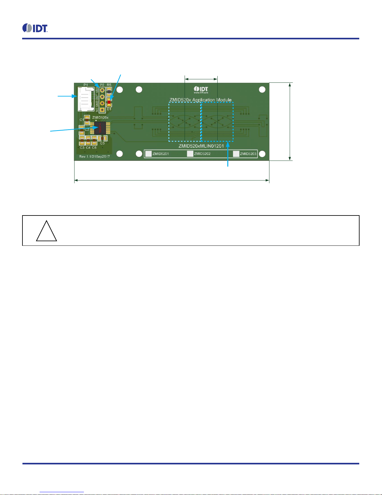
Figure 1. ZMID520x Evaluation Kit and ZMID520x Application Modules
Page 2

ZMID520x Evaluation Kit User Manual
© 2018 Integrated Device Technology, Inc.
2
September 25, 2018
Important Notes
Disclaimer
Integrated Device Technology, Inc. and its affiliated companies (herein referred to as “IDT”) shall not be liable for any damages arising out of defects resulting from
(i) delivered hardware or software
(ii) non-observance of instructions contained in this manual and in any other documentation provided to user, or
(iii) misuse, abuse, use under abnormal conditions, or alteration by anyone other than IDT.
TO THE EXTENT PERMITTED BY LAW, IDT HEREBY EXPRESSLY DISCLAIMS AND USER EXPRESSLY WAIVES ANY AND ALL WARRANTIES, WHETHER
EXPRESS, IMPLIED, OR STATUTORY, INCLUDING, WITHOUT LIMITATION, IMPLIED WARRANTIES OF MERCHANTABILITY AND OF FITNESS FOR A
PARTICULAR PURPOSE, STATUTORY WARRANTY OF NON-INFRINGEMENT, AND ANY OTHER WARRANTY THAT MAY ARISE BY REASON OF USAGE
OF TRADE, CUSTOM, OR COURSE OF DEALING.
Restrictions in Use
IDT’s ZMID520x Evaluation Kit, consisting of the ZMID-COMBOARD and micro-USB cable used in combination with the ZMID520x Application Module and the
ZMID520x AID EVKIT Application Software, is designed for evaluation and configuration of the ZMID520x product family only. IDT’s ZMID520x Evaluation Kit
hardware and software must not be used for characterization measurements in terms of replacing calibrated laboratory environment and measurement devices.
Important Safety Warning: These procedures can result in high currents, which can cause severe injury or death
and/or equipment damage. Only trained professional staff should connect external equipment and operate the software.
Important Equipment Warning: Ensure the correct connection of all cables. Supplying the board using the wrong
polarity could result in damage to the board and/or the equipment.
Contents
1. Setup ............................................................................................................................................................................................................5
1.1 Required User Equipment ...................................................................................................................................................................5
1.2 User Computer Requirements and Setup ...........................................................................................................................................5
1.2.1 Computer Requirements ......................................................................................................................................................5
1.2.2 Software Installation and Setup ............................................................................................................................................5
1.3 Hardware Setup ...................................................................................................................................................................................6
1.3.1 Overview of the Hardware ....................................................................................................................................................6
1.3.2 Connecting the Kit ................................................................................................................................................................9
2. ZMID520x EVKIT Application Software User Guide ...................................................................................................................................10
2.1 Sections of the Display ......................................................................................................................................................................10
2.2 Getting Started ..................................................................................................................................................................................11
2.2.1 Connecting to a Device ......................................................................................................................................................11
2.2.2 Reading Measurements .....................................................................................................................................................13
!
!
Page 3

ZMID520x Evaluation Kit User Manual
© 2018 Integrated Device Technology, Inc.
3
September 25, 2018
2.3 Changing the Configuration Settings .................................................................................................................................................16
2.4 Calibration .........................................................................................................................................................................................18
2.4.1 “COIL OFFSET” Sub-tab ....................................................................................................................................................18
2.4.2 “OUTPUT RANGE” Sub-tab ...............................................................................................................................................21
2.4.3 “CALIBRATION AND LINEARIZATION” Tab .....................................................................................................................26
2.5 Working with the Memory ..................................................................................................................................................................31
2.5.1 “MEMORY EDIT” Tab .........................................................................................................................................................31
2.5.2 Saving and Loading Memory Dump Files ...........................................................................................................................32
2.5.3 Viewing Memory Dump Files without Connecting to a Device (Offline) ..............................................................................33
2.6 Manually Identifying a Device ............................................................................................................................................................34
2.6.1 Identifying an Unknown Device ..........................................................................................................................................34
2.6.2 Re-identifying a Device .......................................................................................................................................................35
3. Firmware Update ........................................................................................................................................................................................36
4. ZMID-COMBOARD Schematics .................................................................................................................................................................37
5. ZMID-COMBOARD BOM ...........................................................................................................................................................................40
6. Sensors Boards ..........................................................................................................................................................................................42
7. Glossary .....................................................................................................................................................................................................42
8. Ordering Information ...................................................................................................................................................................................42
9. Revision History ..........................................................................................................................................................................................43
List of Figures
Figure 1. ZMID520x Evaluation Kit and ZMID520x Application Modules ...........................................................................................................1
Figure 2. ZMID520x Evaluation Kit Connections – ZMID520x Arc Application Module Example .......................................................................6
Figure 3. ZMID-COMBOARD – Overview ..........................................................................................................................................................7
Figure 4. ZMID520x Rotary 360° Application Module – Overview .....................................................................................................................8
Figure 5. ZMID520x Arc 130°Application Module – Overview ............................................................................................................................8
Figure 6. ZMID520x Linear Application Module – Overview ...............................................................................................................................9
Figure 7. Sections of the GUI Display – Example ZMID5203 ...........................................................................................................................10
Figure 8. Start-up Screen .................................................................................................................................................................................11
Figure 9. Display When Connected to a Device – ZMID5203 Example ...........................................................................................................12
Figure 10. Display When Connected to 2 Devices – ZMID5203 Example ..........................................................................................................12
Figure 11. “OUTPUT” Tab – ZMID5203 Example...............................................................................................................................................14
Figure 12. “INTERNAL VALUES” Tab – ZMID5203 Example ............................................................................................................................14
Figure 13. “SENT” Tab (ZMID5203 only) ............................................................................................................................................................15
Figure 14. "CONFIGURE" Tab – Selection of Memory Type to be Displayed ....................................................................................................16
Figure 15. Buttons in the “I/O FUNCTIONS” Section..........................................................................................................................................16
Figure 16. Options on the “SETTINGS” Menu ....................................................................................................................................................17
Figure 17. Example of Numerical Values That Can be Edited ............................................................................................................................17
Figure 18. Example of a Drop-Down Menu with Multiple Choice Values ............................................................................................................17
Page 4

ZMID520x Evaluation Kit User Manual
© 2018 Integrated Device Technology, Inc.
4
September 25, 2018
Figure 19. Example of Read-Only Values ..........................................................................................................................................................17
Figure 20. Example of a Modified Value that is Not Yet Saved to Memory ........................................................................................................17
Figure 21. Example of Tooltip Information ..........................................................................................................................................................17
Figure 22. “COIL OFFSET” Tab – ZMID5203 Example ......................................................................................................................................18
Figure 23. Receiver Coil (ABS Value) Offset Example with Offset Compensation = /2 ..................................................................................19
Figure 24. Coil Offset Calibration Completed – ZMID5203 Example ..................................................................................................................20
Figure 25. “OUTPUT RANGE” Tab – ZMID5201 Example .................................................................................................................................21
Figure 26. Linear Output Mode Example with Slope = 2, Offset = 90° ...............................................................................................................22
Figure 27. Modulus Output Example with Slope = 2, Offset = 60° .....................................................................................................................22
Figure 28. Output without Clamping ...................................................................................................................................................................23
Figure 29. Output Clamped from 20% to 80% ....................................................................................................................................................23
Figure 30. Specify the Original Slope .................................................................................................................................................................24
Figure 31. Request for Changing the Out_Mod Setting ......................................................................................................................................24
Figure 32. Successful Calibration Message .......................................................................................................................................................24
Figure 33. Unsuccessful Calibration Message ...................................................................................................................................................25
Figure 34. "AUTO CAL" Sub-tab – ZMID5201 Example .....................................................................................................................................26
Figure 35. Example Contents of an Input .csv file with Spatial Angle Data ........................................................................................................27
Figure 36. Example Contents of a .csv Input File with Output Voltage Data ......................................................................................................27
Figure 37. Example of AUTO CAL Error Messages ............................................................................................................................................28
Figure 38. “MANUAL LINEARIZATION” Sub-tab – ZMID5201 Example ............................................................................................................29
Figure 39. Calibration Diagram ...........................................................................................................................................................................30
Figure 40. “MEMORY EDIT” Tab Contents – ZMID5201 Example .....................................................................................................................31
Figure 41. Example of a Modified Value on the “MEMORY EDIT” Tab ..............................................................................................................31
Figure 42. Example of “MEMORY EDIT” Tab Tooltip Information ......................................................................................................................32
Figure 43. Menu Options for Saving and Loading Memory Dump Files .............................................................................................................32
Figure 44. Viewing a Memory Dump File "Offline" ..............................................................................................................................................33
Figure 45. GUI View if an Unknown Device is Selected .....................................................................................................................................34
Figure 46. File Dialog to Select an Identification File ..........................................................................................................................................34
Figure 47. “Identify Selected Device” Menu Option ............................................................................................................................................35
List of Tables
Table 1. ZMID-COMMBOARD Key Components and Connector Descriptions .................................................................................................7
Table 2. ZMID520x Application Module: Key Components and Connector Descriptions ..................................................................................8
Table 3. Bill of Materials for ZMID-COMBOARD Rev. 5.1 ...............................................................................................................................40
Page 5

ZMID520x Evaluation Kit User Manual
© 2018 Integrated Device Technology, Inc.
5
September 25, 2018
1. Setup
1.1 Required User Equipment
A Windows®-based computer is required for interfacing with the kit and configuring the ZMID520x.
1.2 User Computer Requirements and Setup
1.2.1 Computer Requirements
The user must have administrative rights on the computer to download and install the ZMID520x EVKIT Application Software for the kit.
The computer must meet the following requirements:
Windows® Vista SP1 or later, 7 (including SP1), 8, 8.1, or 10.
Note: Touch screens are not supported.
Note: Windows® XP is no longer supported. Contact IDT for assistance. See contact information on the last page.
Supported architecture: x86 and x64.
Available USB port.
Internet access for downloading the ZMID520x EVKIT Application Software.
Microsoft® .NET Framework 4.0
1.2.2 Software Installation and Setup
The ZMID520x EVKIT Application Software is not included with the kit. To ensure use of the latest version of the software, it is available for
download free of cost in zip file format from the IDT web site on the web page given on page 1.
Follow these procedures to install the ZMID520x EVKIT Application Software:
1. After downloading the zip file to the user’s computer, extract the contents of the zip file.
2. Double-click on the extracted setup.exe file to activate the installation.
3. Follow the standard installation instructions displayed on the screen and change the installation path if required. If the default path settings
have been used, the software automatically completes the installation and creates an access link on the user’s computer under Start > All
Programs > IDT > ZMID520x EVKIT. The installation dialog offers the option to create a desktop short-cut icon for the software.
Page 6
ZMID520x Evaluation Kit User Manual
© 2018 Integrated Device Technology, Inc.
6
September 25, 2018
1.3 Hardware Setup
This section describes the basic hardware setup of the ZMID520x Evaluation Kit boards and provides a brief overview on the components.
Refer to the user manual for the specific ZMID520x Application Module for the setup required for the target holder, which is shown in Figure 1,
and for further details for the module such as schematics and BOMs. The application module user manuals are available on the IDT product
web pages for the modules: See section 6 for the IDT product web pages for the application modules to download the manuals.
1.3.1 Overview of the Hardware
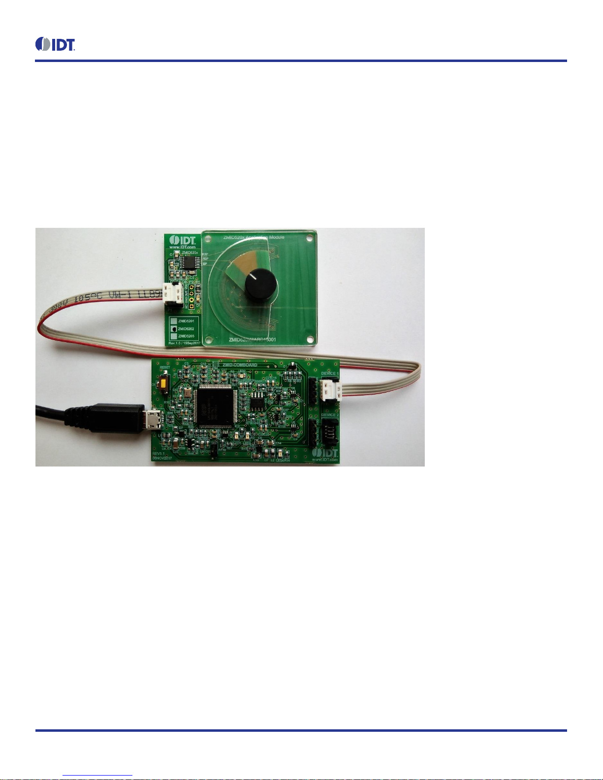
Figure 2 shows the board connections for the ZMID520x Evaluation Kit using the ZMID5201 Arc Application Module (ZMID520xMARC18001)
as an example.
Figure 2. ZMID520x Evaluation Kit Connections – ZMID520x Arc Application Module Example
Page 7
ZMID520x Evaluation Kit User Manual
© 2018 Integrated Device Technology, Inc.
7
September 25, 2018
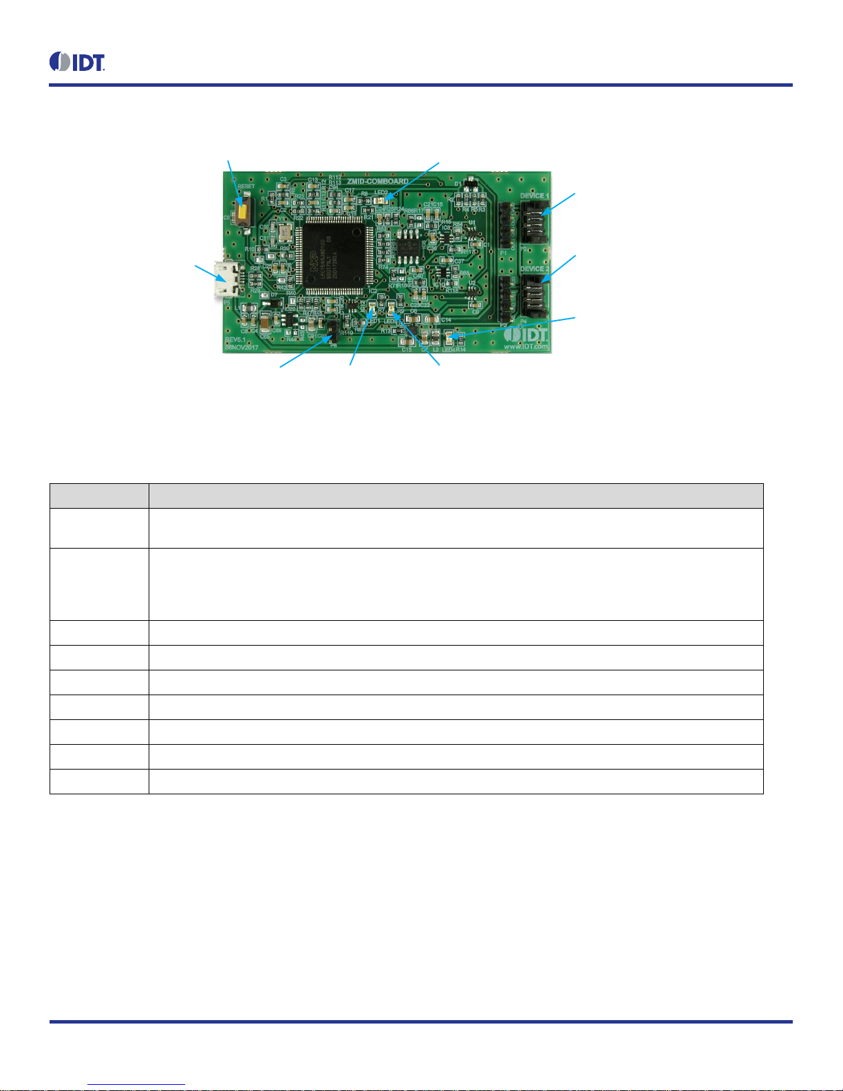
Figure 3. ZMID-COMBOARD – Overview
P5 Micro-USB Connector:
Connect to User s Computer
Reset Button
P2: Connect to Application Module
Sensor Board Via Flat Cable
P4: Connect to Optional Additional Application
Module Sensor Board Via Flat Cable
P8 Boot Pins LED1 (Red):
Fault Indicator
LED2 (Green): Information LED Indicator for Normal Operation Status
LED3 (Blue): Information LED Indicator for
Initialization or Communication
LED4 (Red): Board Power Indicator
Table 1. ZMID-COMMBOARD Key Components and Connector Descriptions
Note: See Figure 3 for the components referenced in this table.
Label
Description
P2
Connector to the ZMID520x Application Module Sensor Board. Note: The same signals are on the adjacent 4-pin header
P1, which has silkscreen labels for the pin signals: NC (no connection), GND, OUT, and VDD.
P4
Alternative connection for the ZMID520x Application Module Sensor Board instead of P2 or for an optional connection
for a second Application Module Sensor Board. If connecting to two modules at the same time, the ZMID520x ICs on the
modules must have the same output option (e.g., 2 x ZMID5201). Note that the same signals are available on the
adjacent 4-pin header P3, which has labels for the pin signals: NC (no connection), GND, OUT, and VDD.
P5
USB connector to the host PC.
P8
Boot pins.
Reset
Reset board button.
LED1 (Red)
Fault indicator LED: ON indicates an error.
LED2 (Green)
Information LED: ON indicates normal operational status.
LED3 (Blue)
Information LED: ON indicates initialization/communication.
LED4 (Red)
Board power indicator.
Figure 4, Figure 5, and Figure 6 give an overview of the different ZMID520x Application Module Sensor Boards before installation of the target
holder for each type of board. The three boards have the same connectors and components given in Table 2 and identified in the figures. Each
board has a silkscreen checkbox that indicates which ZMID520x IC is mounted on the Application Module Sensor Board: ZMID5201, ZMID5202,
or ZMID5203, depending on the order code for the module.
Page 8
ZMID520x Evaluation Kit User Manual
© 2018 Integrated Device Technology, Inc.
8
September 25, 2018
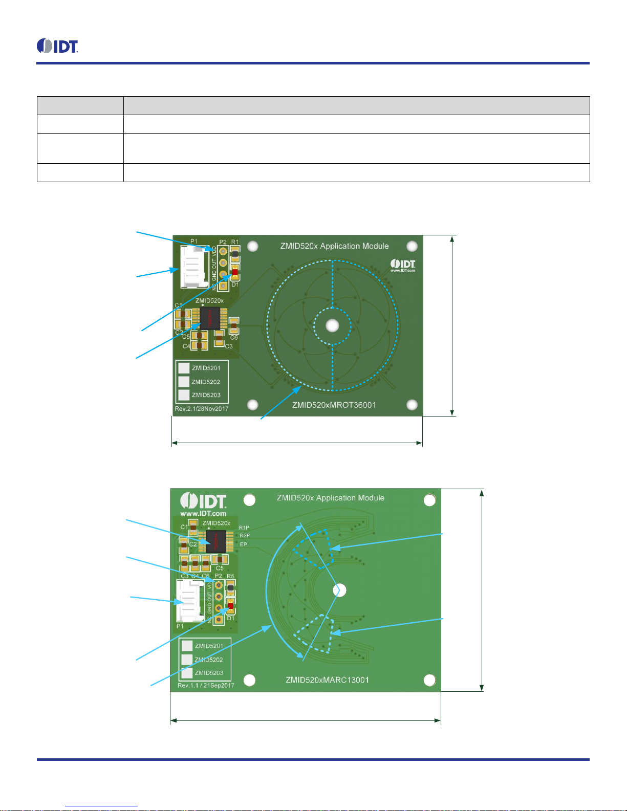
Table 2. ZMID520x Application Module: Key Components and Connector Descriptions
Label
Description
P1
4-pin Molex Picoflex header for cable to the ZMID-COMBOARD.
P2
PCB 4-pin header for de-bugging purposes. If the user’s microcontroller is used instead of the ZMID-COMBOARD, P2 can
be used to connect the microcontroller to the Application Module.
D1
Power Indicator LED for the VDD.
Figure 4. ZMID520x Rotary 360° Application Module – Overview
ZMID520x Sensor IC
P1 Application Module
Connector for the
ZMID-COMBOARD
P2 Application Module
Interface Header for
Troubleshooting Purposes
D1 Power Indicator LED
Measurement Range: 360°
Coil Range: 360°
Target: 180° (50%)
35mm
55mm
Target Positions
Figure 5. ZMID520x Arc 130°Application Module – Overview
ZMID520x Sensor IC
P1 Application Module
Connector for the
ZMID-COMBOARD
P2 Application Module
Interface Header for
Troubleshooting Purposes
D1 Power Indicator LED
Measurement Range: 130°
Coil Range: 180°
Target: 40° (22%)
45mm
60mm
Max.
Target
Position
Max.
Target
Position
Page 9
ZMID520x Evaluation Kit User Manual
© 2018 Integrated Device Technology, Inc.
9
September 25, 2018
Figure 6. ZMID520x Linear Application Module – Overview
ZMID520x
Sensor IC
P1 Application
Module Connector for
ZMID-COMBOARD
P2 Application Module Interface
Header for Troubleshooting Purposes D1 Power Indicator LED
Measurement Range
12mm (50% Target)
30mm
75mm
Target Positions
1.3.2 Connecting the Kit
Important Equipment Warning: Ensure the correct connection of all cables. Supplying the board using the wrong
polarity could result in damage to the board and/or the equipment.
1. Ensure that the ZMID-COMBOARD is not connected to the computer.
2. Assemble the ZMID520x Application Module with the target holder as described in the user manual for the specific application module.
3. Connect the ZMID520x Application Module via the flat cable to the ZMID-COMBOARD as shown in the example for the ZMID520x
Arc Application Module in Figure 2. See Figure 1 for the connections for the ZMID520x Linear Application Module and ZMID520x
Rotary Application Module.
4. Connect the ZMID-COMBOARD to the computer using the micro-USB cable provided in the ZMID-COMBOARD. Power is provided
from the computer via the USB connection. No external power source is required.
5. The indicator LED2 on the ZMID-COMBOARD will light (see Figure 3) if conditions are normal. This indicates that the board is ready
to communicate with the ZMID520x EVKIT Application Software. The D1 LED on the ZMID520x Application Module (see Figure 4,
Figure 5, or Figure 6) also lights when the board is powered on.
!
Page 10
ZMID520x Evaluation Kit User Manual
© 2018 Integrated Device Technology, Inc.
10
September 25, 2018
2. ZMID520x EVKIT Application Software User Guide
2.1 Sections of the Display
The ZMID520x EVKIT Application Software provides a graphic user interface (GUI) for communicating with the kit. The GUI is displayed when
the application is started. Figure 7 identifies the various sections of the display.
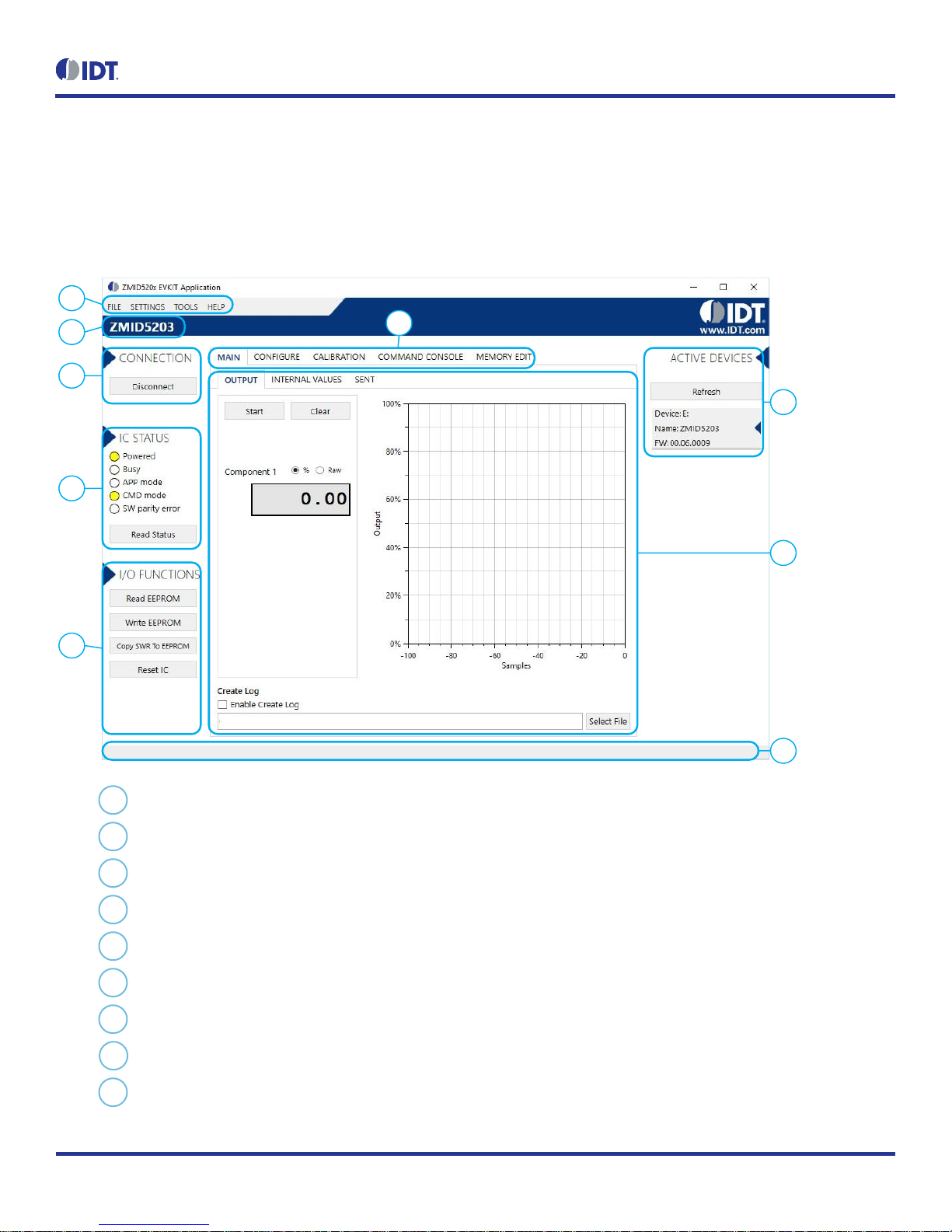
Figure 7. Sections of the GUI Display – Example ZMID5203
1
5
4
7
8
6
3
2
9
Menu bar: Contains settings and tools.
Information label: Displays the name of the connected device.
“CONNECTION” section: Displays connection-related options.
“IC STATUS” section: Displays status information from the connected device.
“I/O FUNCTIONS” section: Displays options to perform READ and WRITE actions on the connected device.
Navigation tabs: Used to switch between the different main window tabs.
“ACTIVE DEVICES” section: Displays a list of the currently connected communication boards.
Main window area: Displays options and information about the connected device.
Status bar: Displays status messages during operation.
1
2 3 4
5 6 7
8
9
Page 11
ZMID520x Evaluation Kit User Manual
© 2018 Integrated Device Technology, Inc.
11
September 25, 2018
2.2 Getting Started
The following steps describe how to establish a connection to the ZMID520x Application Module and perform measurements. The combination
of a ZMID-COMBOARD and its connected ZMID520x Application Module is referred to as the “device” in the GUI.
2.2.1 Connecting to a Device
1. Ensure that the ZMID520x Application Module is properly connected to the ZMID-COMBOARD. See section 1.3.2.
2. Connect the ZMID-COMBOARD to the user’s computer using the micro-USB cable provided in the kit.
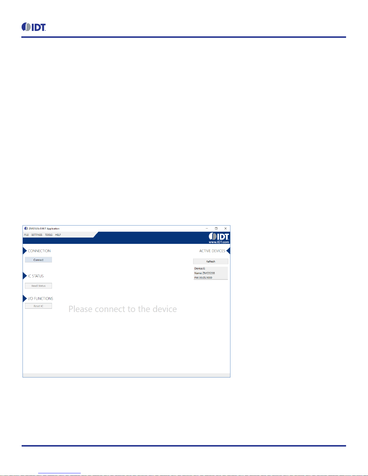
3. Start the GUI application. See Figure 8 for the start-up screen.
4. The device will appear in the “Active Devices” section. If there are no other devices on the list, it will be automatically selected;
otherwise select it by clicking on it.
5. If the device shows as unknown, manually identify the device first. For a description of how to manually identify a device, refer to
section 2.6.
6. Click on the “Connect” button to initialize the connection.
7. After a successful connection, the GUI will display the contents of the main window area.
8. Two sensor boards can also be connected to the ZMID-COMBOARD at the same time; see Figure 10 for an example. Data are
displayed according to the selection made through the drop down menu on the top left side (Module 1 or Module 2). When connecting
to two modules at the same time, both ZMID520x ICs on the modules must have the same output option (e.g., 2 x ZMID5201).
Figure 8. Start-up Screen
Page 12
ZMID520x Evaluation Kit User Manual
© 2018 Integrated Device Technology, Inc.
12
September 25, 2018
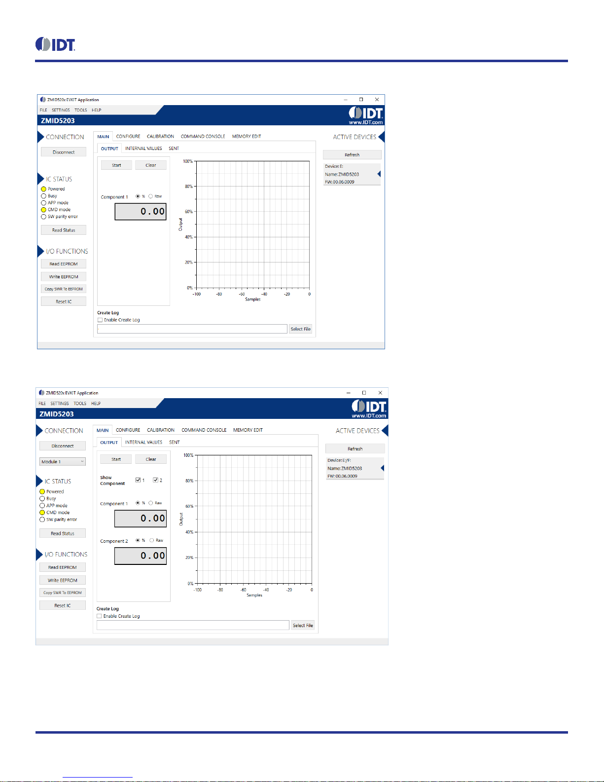
Figure 9. Display When Connected to a Device – ZMID5203 Example
Figure 10. Display When Connected to 2 Devices – ZMID5203 Example
Page 13

ZMID520x Evaluation Kit User Manual
© 2018 Integrated Device Technology, Inc.
13
September 25, 2018
2.2.2 Reading Measurements
1. After connecting to a device, select the “MAIN” tab from the navigation menu. Two sub-tabs “OUTPUT” and “INTERNAL VALUES”
are displayed. For the ZMID5203, the “SENT” sub-tab is also displayed and provides a SENT interface decoder. The “OUTPUT” tab
displays the reading at the ZMID520x output pin SOUT.
2. The readings can be displayed as scaled values in percent or as raw (decimal/hexadecimal) values. Use the “Component 1” radio
buttons (“%” or “Raw”) to select the desired method for presenting the values. If there are two devices, repeat the selection for the
second device using the “Component 2” radio buttons.
The “OUTPUT” tab readings in percent represent
a. Analog values for the ZMID5201 – Percent of VDD
b. PWM values for the ZMID5202 – Duty cycle of the signal
c. SENT values for the ZMID5203 – Percent of the maximum position SENT value (4095)
The “OUTPUT” tab readings in raw data represent
a. Analog values for the ZMID5201 –12-bit value from the ZMID COMBOARD’s ADC with VDD for reference voltage
b. PWM values for the ZMID5202 –12-bit value from the duty cycle calculation
c. SENT values for the ZMID5203 – 12-bit position value decoded from the SENT stream
3. Clicking the “Start” button will activate the measurements and change this button to the “Stop” button. The GUI disables some of its
buttons and options while the measurement is active. Clicking the “Stop” button will deactivate the measurement and reactivate all
options and buttons again.
4. At the bottom of each measurement tab, the “Enable Create Log” check box can be checked to log the measured values into a *.csv
file. The filename and its location are specified with the “Select File” entry field.
The “OUTPUT” tab displays the physical values by using either the ADC or digital inputs of the ZMID-COMBOARD. Figure 11 shows an example
of SENT interface readings. For the PWM or analog interface, the values are captured using an analog-to-digital conversion by the
microcontroller located on the ZMID-COMBOARD. Hence, the accuracy of the measured values is limited due to the setup. The ZMID Evaluation
Kit is a configuration tool – it is not intended to act as a measurement device.
Page 14

ZMID520x Evaluation Kit User Manual
© 2018 Integrated Device Technology, Inc.
14
September 25, 2018
Figure 11. “OUTPUT” Tab – ZMID5203 Example
The “INTERNAL VALUES” tab displays measurements that are only accessible via OWI (see Figure 12). Therefore, all the readings are digital
register contents and not limited in terms of hardware accuracy.
Figure 12. “INTERNAL VALUES” Tab – ZMID5203 Example
Page 15

ZMID520x Evaluation Kit User Manual
© 2018 Integrated Device Technology, Inc.
15
September 25, 2018
There are three controls that can be used to view and change settings on the device:
AGC Mode: Gain and integration time control – used to enable or disable the Automatic Gain Control (AGC) and the Integration Time
Control of the device. The following standard options are available in the drop-down menu:
Gain adaptation and integration time adaptation off
Gain adaptation and integration time adaptation on
Two additional options are available for the AGC Mode that are for advanced testing only. Note: Before using either of these options, contact
IDT support (see the last page for the contact information).
Gain adaptation off and integration time adaptation on
Gain adaptation on and integration time adaptation off
AGC Gain Stage. Depending on the AGC Mode, this control has different behaviors:
When the AGC is active (“Gain and integration time adaptation” is on), the value in the “ACG Gain Stage” entry field specifies the
maximum gain for gain regulation. During measurements, the box becomes read-only and displays the existing gain stage setting that
the ZMID520x is using.
When the AGC is disabled (“Gain and integration time adaptation” is off), the value in the input field specifies the selected gain stage.
Over Sampling Rate (OSR). This parameter defines the number of averaging samples per receiving channel and reduces the noise level
on the signal.
The “SENT” tab is only available when the ZMID5203 Application Module is connected to the ZMID-COMBOARD. It displays the decoded SENT
data information as shown in Figure 13.
Figure 13. “SENT” Tab (ZMID5203 only)
Page 16

ZMID520x Evaluation Kit User Manual
© 2018 Integrated Device Technology, Inc.
16
September 25, 2018
2.3 Changing the Configuration Settings
The “CONFIGURE” tab (see Figure 14) is designed to provide the user with an easy way of viewing and editing the IC configuration. Each value
represents a register or a part of a register from the internal memory of the device. The displayed memory type can be either the ZMID520x
EEPROM or the SWR memory. SWR refers to shadow registers used as the working memory for the ZMID520x, which can be temporarily
written via the GUI to the ZMID520x for development purposes.
Figure 14. "CONFIGURE" Tab – Selection of Memory Type to be Displayed
If parameters in the EEPROM memory selection have been changed, the ZMID520x must be reset after the writing process is finished for the
changes to take effect. This is done automatically after pressing the “Write EEPROM” button in the “I/O FUNCTIONS” section (see Figure 15).
This can be disabled via the “SETTINGS” menu > “Reset on Memory Write.” In the case of the SWR selection, by default, changes are
immediately written to the SWR memory of the ZMID520x. This option can be disabled via the “SETTINGS” menu > “Enable Automatic SWR
Write” (see Figure 16). Clicking the “Write SWR to EEPROM” button in the “I/O FUNCTIONS” section copies all of the current SWR settings to
the EEPROM memory of the device. This section also provides the “Reset IC” button for manually resetting the ZMID520x. The reset power
cycles the device and puts it in Command Mode. After reset, the contents of the EEPROM of the device are copied to its working memory SWR.
Figure 15. Buttons in the “I/O FUNCTIONS” Section
Page 17

ZMID520x Evaluation Kit User Manual
© 2018 Integrated Device Technology, Inc.
17
September 25, 2018
Figure 16. Options on the “SETTINGS” Menu
There are three different data types shown on the “CONFIGURE” tab:
1. Numerical values are displayed in a white field (see Figure 17). If they are hexadecimal, “0x” is automatically inserted at the beginning
of the value.
2. Values with predefined multiple choices are displayed in a drop-down menu (see Figure 18).
3. Read-only values are displayed with a light blue background. They can only be selected and copied (see Figure 19).
Figure 17. Example of Numerical Values That Can be Edited
Figure 18. Example of a Drop-Down Menu with Multiple Choice Values
Figure 19. Example of Read-Only Values
Changing a value will change the font color to red (see Figure 20). This indicates that the change has not yet been applied to the actual memory
(EEPROM or SWR) of the IC. To apply the change, click the corresponding “Write…” button in the “I/O FUNCTIONS” section. If the “Reset IC”
or one of the “Read” buttons is pressed, the values will be set to represent the current settings of the device.
Figure 20. Example of a Modified Value that is Not Yet Saved to Memory
Context-sensitive pop-ups (see Figure 21), referred to as “tooltips,” provide additional information that appears briefly as the cursor hovers over
an element on the screen. The tooltips for entry fields include a brief description of the setting and the address of the internal memory register.
Figure 21. Example of Tooltip Information
Page 18

ZMID520x Evaluation Kit User Manual
© 2018 Integrated Device Technology, Inc.
18
September 25, 2018
2.4 Calibration
There are three sub-tabs under the “CALIBRATION” tab: COIL OFFSET, OUTPUT RANGE, and CALIBRATION AND LINEARIZATION.
2.4.1 “COIL OFFSET” Sub-tab
The “COIL OFFSET” sub-tab is located under the “CALIBRATION” tab (see Figure 22). It is used to compensate the offset of the signal acquired
from coils R1 and R2 connected to the ZMID520x.
Figure 22. “COIL OFFSET” Tab – ZMID5203 Example
For each of the coils, the following are displayed:
1. R1 Offset – Offset applied to the signal from the R1 coil.
2. R2 Offset – Offset applied to the signal from the R2 coil.
The GUI automatically determines which of the coils is the sine and cosine signal based on the current configuration settings. The two signals
are color coded in red and green. When the “Read” button is pressed, the current sine and cosine and their maximal and minimal values are
displayed next to the graph.
Page 19

ZMID520x Evaluation Kit User Manual
© 2018 Integrated Device Technology, Inc.
19
September 25, 2018
Figure 23. Receiver Coil (ABS Value) Offset Example with Offset Compensation = /2
To start the automatic calibration for amplitude offset, click the “Start Offset Compensation” button. The GUI will guide the user through a
sequence of instructions for performing the calibration procedure.
1. Remove the target from the coil, and press “Ok.”
2. Wait for a few seconds for the GUI to measure the offset. It will automatically continue to the next step.
3. Values for the Offset will be updated (see Figure 24).
4. Use the “Write EEPROM” button from the “I/O FUNCTIONS” section to save the new values to the EEPROM.
Page 20

ZMID520x Evaluation Kit User Manual
© 2018 Integrated Device Technology, Inc.
20
September 25, 2018
Figure 24. Coil Offset Calibration Completed – ZMID5203 Example
Page 21

ZMID520x Evaluation Kit User Manual
© 2018 Integrated Device Technology, Inc.
21
September 25, 2018
2.4.2 “OUTPUT RANGE” Sub-tab
The “OUTPUT RANGE” sub-tab (see Figure 25) is used to configure the output behavior of the ZMID520x. For a detailed description of output
settings, refer to the ZMID520x Datasheet.
Figure 25. “OUTPUT RANGE” Tab – ZMID5201 Example
There are four values that can be edited on the “OUTPUT RANGE” sub-tab for subsequent use during the calibration procedure:
The “Output Start Point [%]” field defines the desired output value when the target is at the mechanical start point.
The “Output End Point [%]” field defines the desired output value when the target is at the mechanical end point.
The “Apply Clamps” checkbox is available only for the ZMID5201 (analog interface) and the ZMID5202 (PWM interface). If activated, the
output is clamped between the specified start and end points if the target goes beyond these mechanical positions. Due to the low
resolution of the clamps register, the available clamping values might not match the selected output start and end points exactly. See
Figure 28 and Figure 29 for examples of the output without clamping and the output with clamping, respectively.
Out MOD: Defines the output mode.
Linear: The Linear Output Mode is a non-repeating output mode in which the sensor output signal is clamped at the mechanical end
points (see Figure 26).
Modulo 360: The Modulo Output (saw tooth output) Mode is a repeating output mode in which the sensor output signal is not clamped
at the mechanical end points, but it is switched back to its origin (see Figure 27).
Page 22

ZMID520x Evaluation Kit User Manual
© 2018 Integrated Device Technology, Inc.
22
September 25, 2018
Figure 26. Linear Output Mode Example with Slope = 2, Offset = 90°
Figure 27. Modulus Output Example with Slope = 2, Offset = 60°
The results from the calibration procedure are displayed in two fields on the “OUTPUT RANGE” tab. They are direct representations of the
Offset and Slope registers in the ZMID520x. The values can also be manually entered by the user.
Slope: The slope of the transfer function of the output signal.
Offset: The zero-offset of the output signal referenced to the mechanical position in degrees.
0
10000
20000
30000
40000
50000
60000
70000
0 50 100 150 200 250 300 350
Output position [decimal]
Electrical input range [degree]
Linear mode example
Output
Spatial Angle
0
10000
20000
30000
40000
50000
60000
70000
0 50 100 150 200 250 300 350
Output position [decimal]
Electrical input range [degree]
Modulus mode example
Output
Spatial Angle
Page 23

ZMID520x Evaluation Kit User Manual
© 2018 Integrated Device Technology, Inc.
23
September 25, 2018
Figure 28. Output without Clamping
Figure 29. Output Clamped from 20% to 80%
Automatic Output Calibration Procedure:
To start the automatic calibration, click the “Start Calibration” button. The GUI will guide the user through a sequence of instructions for performing the calibration procedure.
1. Move the sensing target to the start position, and click “OK” in the dialog box. The graph will start displaying the internal reading of
the position.
2. Move the sensing target to the end position, and click OK. The GUI will automatically attempt to determine if the slope polarity of the
values is positive (values ascending) or negative (values descending). If this cannot be determined, the GUI will ask the user to specify
the polarity of the slope. For the example provided in Figure 30, the slope is negative.
Page 24

ZMID520x Evaluation Kit User Manual
© 2018 Integrated Device Technology, Inc.
24
September 25, 2018
3. Based on the acquired data, the GUI will attempt to calculate the best values for the Slope, Offset, and Clamps registers. If the
calibration is not possible with the currently selected “Out MOD” setting, the GUI will ask the user to change to the other setting (see
Figure 31). The calculated values will be prepared to be written to the memory, and the user will be directed to use the “Write EEPROM”
button in the “I/O FUNCTIONS” section to write the new coefficients to the memory of the device. See Figure 32.
4. If the calculated values are out of range or the calibration is not possible, a message will inform the user which value is affected. The
most common cause of unsuccessful calibration is setting the start and end target positions too close to each other since this could
require a slope value larger than the valid range of slope values. See Figure 33.
5. A detailed log from the calibration function is available from the “TOOLS” menu > “Open Log File” > “Calibration.”
Figure 30. Specify the Original Slope
Figure 31. Request for Changing the Out_Mod Setting
Figure 32. Successful Calibration Message
Page 25

ZMID520x Evaluation Kit User Manual
© 2018 Integrated Device Technology, Inc.
25
September 25, 2018
Figure 33. Unsuccessful Calibration Message
Page 26

ZMID520x Evaluation Kit User Manual
© 2018 Integrated Device Technology, Inc.
26
September 25, 2018
2.4.3 “CALIBRATION AND LINEARIZATION” Tab
The “CALIBRATION AND LINEARIZATION” tab contains two sub-tabs. The “AUTO CAL” sub-tab is used to perform the full output range
calibration and linearization on a device by importing a .csv file with position measurements. The “MANUAL LINEARIZATION” sub-tab can be
used to manually calculate the linearization register values for given target positions.
2.4.3.1 “AUTO CAL” Sub-tab
The “AUTO CAL”” sub-tab is located under the “CALIBRATION AND LINEARIZATION” tab (see Figure 34). It is used to do a full calibration of
the ZMID520x by processing a .csv file with measurement data.
Figure 34. "AUTO CAL" Sub-tab – ZMID5201 Example
Page 27

ZMID520x Evaluation Kit User Manual
© 2018 Integrated Device Technology, Inc.
27
September 25, 2018
The "AUTO CAL" sub-tab has the following input parameters:
The “Select File” button is used to specify the path to the .csv file with measurement data that will be used for the calibration. By default,
the file should contain only raw Spatial Angle register readings taken at equal intervals during the whole movement range of the target.
The header row in the .csv file is optional. The values are written as 16-bit unsigned integers [0 to 65535].
Figure 35. Example Contents of an Input
.csv
file with Spatial Angle Data
If the “Use Analog values instead of Spatial Angle” checkbox is selected, the input .csv file should contain only voltage readings from the
output of the ZMID5201 taken at equal intervals during the whole movement range of the target. The values are written as positive real
numbers in volts.
Note: This option is only available for ZMID5201.
Figure 36. Example Contents of a
.csv
Input File with Output Voltage Data
Page 28

ZMID520x Evaluation Kit User Manual
© 2018 Integrated Device Technology, Inc.
28
September 25, 2018
The “VDD [V]” text box is used to specify the measured supply voltage of the ZMID5201 when the .csv data was gathered.
Note: This option is only available for the ZMID5201.
The “Write IDT Output Config” button writes a default configuration to the first 8 registers of the EEPROM to allow the analog
measurements of the device to be converted to spatial angle values.
Note: This option is only available for the ZMID5201.
The “Spatial Angle Slope” radio buttons specify the polarity of the slope of the .csv input values. A positive slope means that the .csv input
values are increasing; a negative slope means the values are decreasing.
The “Reverse slope of Pos0” checkbox specifies whether the polarity of the slope of the calibrated values should be the same as the
polarity of the Spatial Angle slope values or inverted.
The “Out Mod” radio buttons specify the type of the calibration: Linear or Modulo360.
The “Apply clamps” checkbox specifies whether the clamp register will be used to set clamp levels on the output that correspond to the
minimal and maximal output calibration points.
Note: This option is only available for the ZMID5201 and ZMID5202.
The “Out min” and “Out max” text boxes are the desired output values in percent at the two mechanical movement end points. The
minimal value should be less than the maximal value.
The “Calculate” button calls the OneStepCalibration.dll library with the specified input parameters to calculate the calibration coefficients.
After a successful calibration, the output fields are populated with the calculated calibration data. The left column shows the values in
“human readable” format, and the right column shows the corresponding register data that will be written to the memory of the ZMID520x.
Offset: The zero-offset of the output signal referenced to the mechanical position in degrees.
Slope: The slope of the transfer function of the output signal.
Clamp Low and Clamp High: Actual output clamping levels.
LinInt 1 to 9: The correction coefficients at the 9 linear interpolation correction points.
A successful calibration will prepare the new values to be written to the EEPROM memory of the ZMID520x. To write the values, click the “Write
EEPROM” button in the “I/O FUNCTIONS” section.
An unsuccessful calibration will only provide an error message.
Figure 37. Example of AUTO CAL Error Messages
Page 29

ZMID520x Evaluation Kit User Manual
© 2018 Integrated Device Technology, Inc.
29
September 25, 2018
A detailed report of the calibration can be viewed in the calibrationLogfile.txt log file, which is accessible through the Tools > Open Log File >
Calibration menu.
2.4.3.2 “MANUAL LINEARIZATION” Sub-tab
The table on the “MANUAL LINEARIZATION” tab shows the nine points for which a value can be specified for application to a correction curve
over the position range (see Figure 38).
The table has the following rows:
Correction Point: Constraint points for linearization 1 to 9; below each correction point, the electrical position is shown in the next row (0 to
360 degrees in pre-calibration or 0 to 100% after calibration).
Ideal Value: The ideal value (read-only) according to the motion range provided.
Measured Value [mm] or [deg]: Entry field for values measured at the correction points (“mm” is not applicable to the ZMID520x Rotary
360 Application Module or the ZMID520x Arc 130 Application Module). These values are entered by the user.
Correction: These read-only values (integers in the range of -127 to 127) will be added (after a multiplication x 32) to the “Spatial Angle”
data if linearization is performed before calibration; in the case of linearization post-calibration, these values will be applied (after a
multiplication x 32) to the Position 0 data, resulting in the Position 1 data. See the description of the “Start Reading” button below for an
explanation of the “Position 0” and “Position 1” data fields.
Three additional controls are available on this tab.
Motion Range [mm] or [deg]: Entry field for the linear motion range in mm (not applicable to the ZMID520x Rotary 360 Application
Module and the ZMID520x Arc 130 Application Module) or the arc/rotation motion range in degrees. This user-selected value is used to
calculate the ideal values.
Correction Mode: This drop-down menu allows selecting whether the linearization is applied before or after calibration.
Angle Offset: This drop-down menu offers the option to shift the linearization points if required. Whether the offset is applied or not is
determined by the non-linearity error distribution. (Refer to the ZMID520x Datasheet for details).
Figure 38. “MANUAL LINEARIZATION” Sub-tab – ZMID5201 Example
Page 30

ZMID520x Evaluation Kit User Manual
© 2018 Integrated Device Technology, Inc.
30
September 25, 2018
The “Start Reading” button triggers a continuous reading of the three internal position registers of the ZMID520x (see Figure 38 for the
corresponding measurement points in the calibration process). This is implemented to help the user measure the linearization error at the
specific points.
The “Spatial Angle” reading represents the CORDIC output angle before applying the slope and offset calibration. The “Position 0” reading
is the position value after applying the slope and offset calibration but before applying the linear interpolation. The “Position 1” reading is
the final value after the linear interpolation is applied (see Figure 39)
The “Calculate Correction” button re-calculates the new correction values for the EEPROM registers based on the “Measured Value” cells.
To save changes to the device, use the corresponding “Write…” button in the “I/O FUNCTIONS” section.
Figure 39. Calibration Diagram
Spatial Angle
Position 0 Position 1
0, -22.5° Shift in the
Interpolation Factor Position
2.4.3.3 “MANUAL LINEARIZATION” Tab – Correction Values
Multiple strategies have been developed to obtain the set of correction values. For relevant information and procedures, contact IDT support.
(See the contact information on the last page.)
Page 31

ZMID520x Evaluation Kit User Manual
© 2018 Integrated Device Technology, Inc.
31
September 25, 2018
2.5 Working with the Memory
2.5.1 “MEMORY EDIT” Tab
Information for all the memory types of the device and their values can be found on the “MEMORY EDIT” tab (see Figure 40). The data is
organized in tables, and the register values are in hexadecimal format.
Figure 40. “MEMORY EDIT” Tab Contents – ZMID5201 Example
The read-only registers are marked with a light blue background. Modified register values will appear in red color until they are written to the
device memory or re-read from it (see Figure 41).
Figure 41. Example of a Modified Value on the “MEMORY EDIT” Tab
Placing the cursor over a table cell displays a tooltip with additional information about the register (see Figure 42).
Page 32

ZMID520x Evaluation Kit User Manual
© 2018 Integrated Device Technology, Inc.
32
September 25, 2018
Figure 42. Example of “MEMORY EDIT” Tab Tooltip Information
2.5.2 Saving and Loading Memory Dump Files
The current memory configuration can be saved to a file via the “FILE” menu > “Save Memory Dump.” This is useful for providing a backup of
the verified memory configuration or for copying a configuration to another device (see Figure 43).
The “Load Memory Dump” option loads a selected memory dump file into the “MEMORY EDIT” tab. The “Write EEPROM” button in the “I/O
FUNCTIONS” section must be used to write the configuration into the memory of the ZMID520x.
The GUI provides a set of default memory dump files that can be used to easily return a device to its original settings.
The default memory dump files can be found in the “MemoryDumps” folder located in the main installation directory of the GUI.
Figure 43. Menu Options for Saving and Loading Memory Dump Files
Page 33

ZMID520x Evaluation Kit User Manual
© 2018 Integrated Device Technology, Inc.
33
September 25, 2018
2.5.3 Viewing Memory Dump Files without Connecting to a Device (Offline)
It is possible to load a memory dump file when no device is connected. This allows the user to view and edit the contents of a memory dump
file. The “Save Memory Dump” menu option is used to save the changes to the same file or a new file. Since there is no device connected, only
the “CONFIGURE” and “MEMORY EDIT” tabs are available (see Figure 44). The values that are different from the default values for the
ZMID520x are displayed in red. Connecting to a device while viewing a memory dump file “offline” will cause the GUI to discard any unsaved
changes to the memory dump file and switch to displaying the current settings from the connected device’s memory.
Figure 44. Viewing a Memory Dump File "Offline"
Page 34

ZMID520x Evaluation Kit User Manual
© 2018 Integrated Device Technology, Inc.
34
September 25, 2018
2.6 Manually Identifying a Device
When a new device is connected to the computer, the GUI automatically recognizes it. If it is unable to identify the device, the user must
manually identify it. There is also a menu option to re-identify a device (see Figure 45).
2.6.1 Identifying an Unknown Device
If the GUI is unable to automatically identify the device, it will be displayed as an unknown device in the “ACTIVE DEVICES” section, and the
“Connect” button will be replaced by an “Identify Device” button.
Figure 45. GUI View if an Unknown Device is Selected
Follow these steps to identify an unknown device:
1. Select the device by clicking on it in the “ACTIVE DEVICES” section.
2. Click on the “Identify Device” button in the “CONNECTION” section.
3. In the resulting common file dialog, select the proper identification file based on the type of ZMID520x Application Module, and click “Open.”
The identification files can be found in the root directory in the Profiles folder (see Figure 46). Filenames with the suffix “_d” are used if two
application modules are connected.
4. The GUI will identify the device and automatically connect to it.
Figure 46. File Dialog to Select an Identification File
Page 35

ZMID520x Evaluation Kit User Manual
© 2018 Integrated Device Technology, Inc.
35
September 25, 2018
2.6.2 Re-identifying a Device
1. Ensure the GUI is not connected to any device.
2. Select the device to identify from the “ACTIVE DEVICES” list by clicking on it.
3. Open the “TOOLS” menu, and select the “Identify Selected Device” menu option.
4. In the resulting common file dialog, select the proper identification file based on the type of ZMID520x Application Module, and click
“Open.” Filenames with the suffix “_d” are used if two application modules are connected.
5. The GUI will re-identify the device with the selected identification file and update the device information in the “ACTIVE DEVICES”
section.
Figure 47. “Identify Selected Device” Menu Option
Page 36

ZMID520x Evaluation Kit User Manual
© 2018 Integrated Device Technology, Inc.
36
September 25, 2018
3. Firmware Update
This section provides optional instructions for upgrading the firmware for the ZMID-COMBOARD if needed for special uses of the kit that might
require additional features in the latest version of the firmware. Normally this is not needed since all versions of the firmware function properly
with the GUI and hardware. To determine the existing version of the firmware on the board, see the “FW” version shown in the “ACTIVE
DEVICES” section at the right of the display (see Figure 9).
Important Equipment Warning: Ensure the correct connection of all cables. Supplying the board using the wrong
polarity could result in damage to the board and/or the equipment.
To perform a firmware update of the ZMID-COMBOARD, complete these steps:
1. Download the latest firmware file from the IDT website.
2. Disconnect the ZMID-COMBOARD from the USB port of the computer.
3. Install a jumper to short the two “BOOT” pins on the ZMID-COMBOARD as shown in Figure 3.
4. Connect the ZMID-COMBOARD to the USB port of the computer.
5. The ZMID-COMBOARD will show up as a removable drive named “CRP DISABLD.” Open the drive to browse the files.
Figure 43. Locating the Removable Device
6. Delete the “firmware.bin” file from the device. Recommendation: Store a copy of the file on the user’s computer as a backup.
7. Copy the new firmware file to the device.
8. Disconnect the board from the USB port of the computer.
9. Remove the jumper from the “BOOT” pins.
To verify the firmware update, install a ZMID520x Application Module and connect to the computer. The GUI will now display the new version
of the firmware on the board information in the “ACTIVE DEVICES” section.
!
Page 37

ZMID520x Evaluation Kit User Manual
© 2018 Integrated Device Technology, Inc.
37
September 25, 2018
4. ZMID-COMBOARD Schematics
Page 38

ZMID520x Evaluation Kit User Manual
© 2018 Integrated Device Technology, Inc.
38
September 25, 2018
Page 39

ZMID520x Evaluation Kit User Manual
© 2018 Integrated Device Technology, Inc.
39
September 25, 2018
Page 40

ZMID520x Evaluation Kit User Manual
© 2018 Integrated Device Technology, Inc.
40
September 25, 2018
5. ZMID-COMBOARD BOM
Table 3. Bill of Materials for ZMID-COMBOARD Rev. 5.1
Note: DNP = Do not populate.
Item
Designator
Value
Description
Footprint
Qty.
1
C1, C4, C5, C8, C9,
C17, C19, C40, C36,
C37, C25
100nF
100nF 16V X7R +-10%
0603
11
2
C2, C3, C12, C13,
C16, C21, C22, C23
2.2nF
2.2nF 50V X7R +-10%
0603
8
3
C6, C7, C14
2.2µF
2.2uF 16V X7R +-10%
0805
3
4
C10, C11
22pF
22pF 50V C0G +-5%
0603
2 5 C15
4.7µF
4.7uF 25V X5R +-10%
0805
1 6 C18, C20, C26
10nF
10nF 50V X7R +-10%
0603
3 7 C24
820pF
820pF 50V C0G +-5%
0603
1
8
C65
10µF
10uF 25V X7R +-10%
1206
1
9
C89, C93
220nF
220nF 16V X7R +-10%
0603
2
10
C91
10µF
10uF 16V X5R +-10%
0805
1
11
C94
1nF
1.0nF 50V C0G +-5%
0603
1
12
D1
BAT54A
Schottky 30V 2x200mA 5ns 10pF, konf A
SOT23
1
13
D7
STPS1L40M
STMICROELECTRONICS - Schottky Rectifier, 40
V, 1 A, Single, DO-216AA, 2 Pins, 460 mV
DO216AA
1
14
IC2
LPC1549
NXP - ARM Microcontroller, LPC1500 ARM CortexM3 Microcontrollers, 32bit, 72 MHz, 256 KB, 36 KB,
100 Pins
LQFP-100
1
15
IC6
MCP6002-I/SN
2 OA,4.5mV,1pA,1.8-6V,100uA,1MHz
SOIC-8
1
16
IC8, IC10, IC12
SN74LVC1T45
Dual Supply Translating Transceiver 3-State
SC70
3
17
IC22
XC6204B332MR
LDO Voltage Regulators 300mA CMOS LDO 2.5V
to 13.2V
SOT23-5
1
18
L1
EMI Bead 3A 50mR
Ferrite bead 0805, typ. 30Ohm@100MHz,
15mOhm@3.0A
0805
1
19
L2
10µH
inductor 10uH 60mA 0.5ohm 30%
0805
1
20
LED1, LED4
Red LED
2.0x1.25mm 150mcd/20mA 625nm Red 120°
0805
2
21
LED2
Green LED
2.0x1.25mm, 3.2-15mcd@20mA, 568nm Green,
W.Clear, 120°
0805
1
22
LED3
Blue LED
2.0x1.25mm, 36-100mcd@20mA, 470nm Blue,
W.Clear, 120°
0805
1
23
P1, P3
Header 1X4
Header, contact height 6.0mm, 1x4, straight PCB
TH, P2.54mm
HS1X4M
2
Page 41

ZMID520x Evaluation Kit User Manual
© 2018 Integrated Device Technology, Inc.
41
September 25, 2018
Item
Designator
Value
Description
Footprint
Qty.
24
P2, P4
DEV1, DEV2
Wire-To-Board Connector, 1.27 mm, 4 Contacts,
Header, Picoflex 90325 Series, Through Hole, 1
Rows
molex 4pin
2
25
P5
USB_micro_B_Attend
MICRO USB 2.0; B-Type Receptacle; Right Angle;
Shell DIP/Tail SMD
USB_micro_B_SMD
1
26
P8
Header 1X2
Header, contact height 6.0mm, 1x2, straight PCB
TH, P2.54mm
HS1X2M
1
27
R1, R11
100Ω
RES SMD 0603 1% 200ppm 100R 1/10W
0603
2
28
R2, R3, R10, R39,
R40, R42, R45, R47,
R22, R23
10kΩ
RES SMD 0603 1% 100ppm 10K 1/10W
0603
10
29
R4, R5
680Ω
RES SMD 0603 1% 100ppm 680R 1/10W
0603
2
30
R15, R16
510Ω
RES SMD 0603 1% 100ppm 510R 1/10W
0603
2
31
R7, R8, R9,
1kΩ
RES SMD 0603 1% 100ppm 1.0K 1/10W
0603
3
32
R14
2.2kΩ
RES SMD 0603 1% 100ppm 2.2K 1/10W
0603
1
33
R24,R61,R73
820Ω
RES SMD 0603 1% 100ppm 820R 1/10W
0603
3
34
R25,R62,R74
1.3kΩ
RES SMD 0603 1% 100ppm 1.3K 1/10W
0603
3
35
R17, R18
DNP
0603
2
36
R28, R29
22Ω
RES SMD 0603 1% 200ppm 22R 1/10W
0603
2
37
R43
DNP
1
38
R44
DNP
1
39
R112, R113
5.1kΩ
RES SMD 0603 1% 100ppm 5.1K 1/10W
0603
4
40
R64, R65, R67
51kΩ
RES SMD 0603 1% 100ppm 51K 1/10W
0603
3
41
R66, R71, R21, R13,
R6, R12
0Ω
RES SMD 0603 JUMPER MAX 50mOhm
0603
6
42
R117, R118, R119
22kΩ
RES SMD 0603 1% 100ppm 22K 1/10W
0603
3
43
RESET
DTSM-31Y
Tact sw. 2p SPST Mom. 50mA/12V 3.5x6mm SMD
3.5x6mm SMD
1
44
U1, U2
TS5a4624
Analog Switch, SPDT, 1 Channels, 0.7 ohm, 1.65V
to 5.5V, SC-70, 6 Pins
SC-70
2
45
U3
TPS60150DRVR
5 V, Step-Up Charge Pump Regulator
WSON-6
1
46
Y1
12MHz QKT-3225
crystal Fund 12.000 MHz 3.2x2.5mm SMD (DFN)
15ppm 8pF -20+70°C
SMD-3.2X2.5
1
Page 42

ZMID520x Evaluation Kit User Manual
© 2018 Integrated Device Technology, Inc.
42
September 25, 2018
6. Sensors Boards
Refer to the following IDT product web pages for the manuals for specific ZMID520x Application Module manuals for a complete description of
the sensors boards:
ZMID520x Linear Application Module
www.IDT.com/ZMID5201MLIN
www.IDT.com/ZMID5202MLIN
www.IDT.com/ZMID5203MLIN
ZMID520x Rotary 360 Application Module
www.IDT.com/ZMID5201MROT
www.IDT.com/ZMID5202MROT
www.IDT.com/ZMID5203MROT
ZMID520x Arc 130 Application Module
www.IDT.com/ZMID5201MARC
www.IDT.com/ZMID5202MARC
www.IDT.com/ZMID5203MARC
7. Glossary
Term
Definition
ADC
Analog-to-Digital Converter
AGC
Automatic Gain Control
CSV
Comma Separated Values – a file format that can be imported in spreadsheets.
EEPROM
Electrically Erasable Programmable Read-Only Memory – the storage memory of the ZMID520x IC
EVK
Evaluation Kit
GUI
Graphical User Interface – refers to the application used for communication with the kit
OWI
One-Wire Interface
PWM
Pulse Width Modulation
SENT
Single Edge Nibble Transmission
SWR
Shadow Register – used as working memory for the ZMID520x IC.
USB
Universal Serial Bus
8. Ordering Information
Refer to the product pages for the specific ZMID520x Application Module for the order codes for the module.
Orderable Part Number
Description
ZMID-COMBOARD
ZMID-COMBOARD, micro-USB cable
Page 43

ZMID520x Evaluation Kit User Manual
© 2018 Integrated Device Technology, Inc.
43
September 25, 2018
9. Revision History
Revision Date
Description of Change
September 25, 2018
Updates for new version of software.
Updates for addition of Auto Cal GUI tab.
Updates for discontinuation of software support for Windows® XP.
Minor edits.
December 10, 2017
Initial release.
Corporate Headquarters
6024 Silver Creek Valley Road
San Jose, CA 95138
www.IDT.com
Sales
1-800-345-7015 or 408-284-8200
Fax: 408-284-2775
www.IDT.com/go/sales
Tech Support
www.IDT.com/go/support
DISCLAIMER Integrated Device Technology, Inc. (IDT) and its affiliated companies (herein referred to as “IDT”) reserve the ri ght to modify the products and/or specifications described herein at any time,
without notice, at IDT's sole discretion. Performance specifications and operating parameters of the described products are determined in an independe nt state and are not guaranteed to perform the same
way when installed in customer products. The information contained herein is pr ovided without representation or warranty of any kind, whether express or implied, including, but not limited to, the suitabi lity
of IDT's products for any particular purpose, an implied warranty of merchantability, or non -infringement of the intellectual property rights of others. This document is presented only as a guide and does not
convey any license under intellectual property rights of IDT or any third parties.
IDT's products are not intended for use in applications involving extreme environmental conditions or in life support systems or similar devices where the failure or malfunction of an IDT product can be
reasonably expected to significantly affect the health or safety of users. Anyone using an IDT product in such a manner does so at their own risk, absent an express, written agreement by IDT.
Integrated Device Technology, IDT and the IDT logo are trademarks or registered trademarks of IDT and its subsidiaries in the United States and other countries. Other trademarks used herein are the
property of IDT or their respective third party owners. For datasheet type definitions and a glossary of common terms, visit www.idt.com/go/glossary. All contents of this document are copyright of Integrated
Device Technology, Inc. All rights reserved.
 Loading...