

Page 1
USB-BRIDGEV2-EVAL
August 3, 2015 Rev. V2.0
1
© 2015 Integrated Device Technology, Inc.
Evaluation Board Manual
PC – USB to I2C Interface Adapter
Features
Simple USB to I2C interface for IDT evaluation Kits
Additional Digital and Analog I/O option
IDT Test Interface bridge for supported IDT devices
Fully assembled
Micro USB connector with Cable included
Firmware update option
LED status indicators
Evaluation Kit Contents
USB-BRIDGEV2-EVAL board
USB A to micro-USB AB cable
USB-BRIDGEV2-EVAL manual
CD containing:
- Electronic copy of USB-BRIDGEV2-EVAL manual
- PC USB Driver for Windows
Description
The USB-BRIDGEV2-EVAL USB Interface adapter board
provides quick access to the I2C and other features of
various IDT devices.
The tool is designed to allow PC based graphical user
interface access via I2C interface, general purpose I/Os,
analog input as well as IDT’s proprietary OTP (One Time
Programmable) Memory interface.
The board supports a I2C voltage level adjustment to the
target system and an onboard 1.8V regulator for 1.8V
slave-I2C operation in addition to the 5V USB derived
operation.
The board allows easy access via the USB micro AB
connector and included PC driver Software Package.
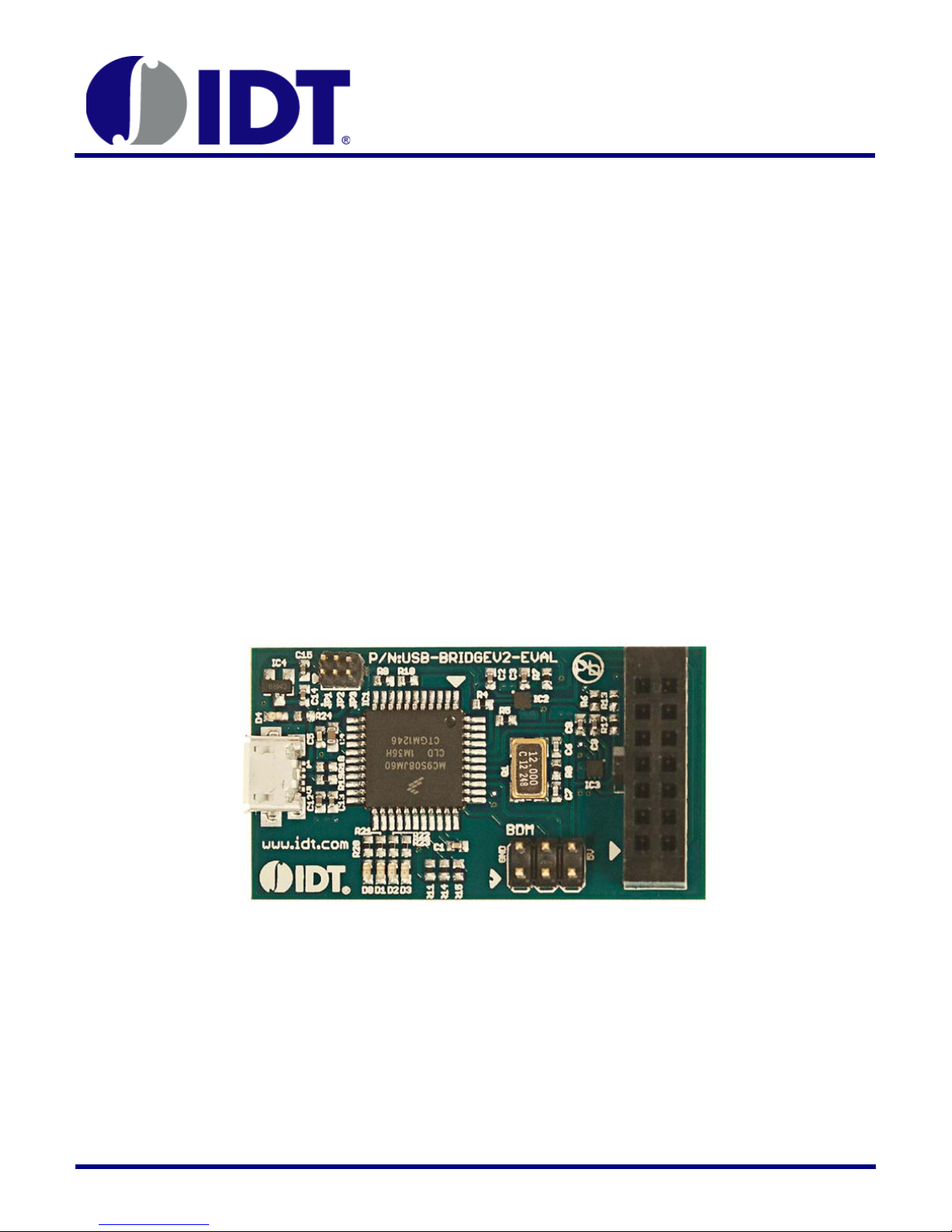
Figure 1 - USB-BRIDGEV2-EVAL, Full board image (not to scale)
Page 2

USB-BRIDGEV2-EVAL
August 3, 2015 Rev. V2.0
2
© 2015 Integrated Device Technology, Inc.
Evaluation Board Manual
Table of Contents
Table of Contents .............................................................. 2
Revision History ................................................................ 2
Windows Driver Installation for Windows XP to Win7 ....... 3
Windows Driver Installation for Windows 8 ....................... 5
Device Configuration ......................................................... 9
Schematic ....................................................................... 10
Ordering Guide ................................................................ 11
Revision History
August 3, 2015 Version 2.0
April 24, 2013 Version 1.0
Page 3
USB-BRIDGEV2-EVAL
August 3, 2015 Rev. V2.0
3
© 2015 Integrated Device Technology, Inc.
Evaluation Board Manual
Windows Driver Installation for Windows XP to Win7
The first time the USB-BRIDGEV2-EVAL is used the Windows Drivers must be instal led.
2
The installation of the Windows USB-to I
following steps:
1. Connect the USB-BRIDGEV2-EVAL without any target evaluation system connected to your PC via the USB cable
included.
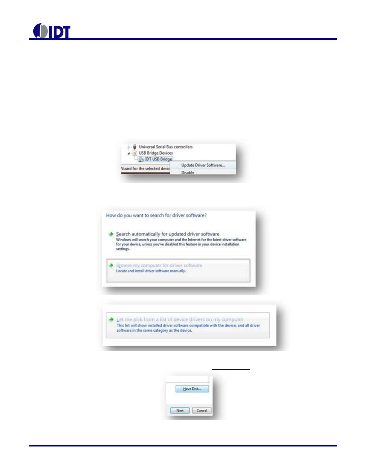
2. Choose Update in the Device Manager or follow the instructions for a new device found after first connect of the
interface.
C-interface on a Windows (XP to Win7) 32-bit or 64-bit system is shown by the
3. Browse manually for the driver location:
4. Choose “Have a Disk” and select the “idt_usb_bridge.inf” from the uncompressed driver folder.
Page 4
USB-BRIDGEV2-EVAL
August 3, 2015 Rev. V2.0
4
© 2015 Integrated Device Technology, Inc.
Evaluation Board Manual
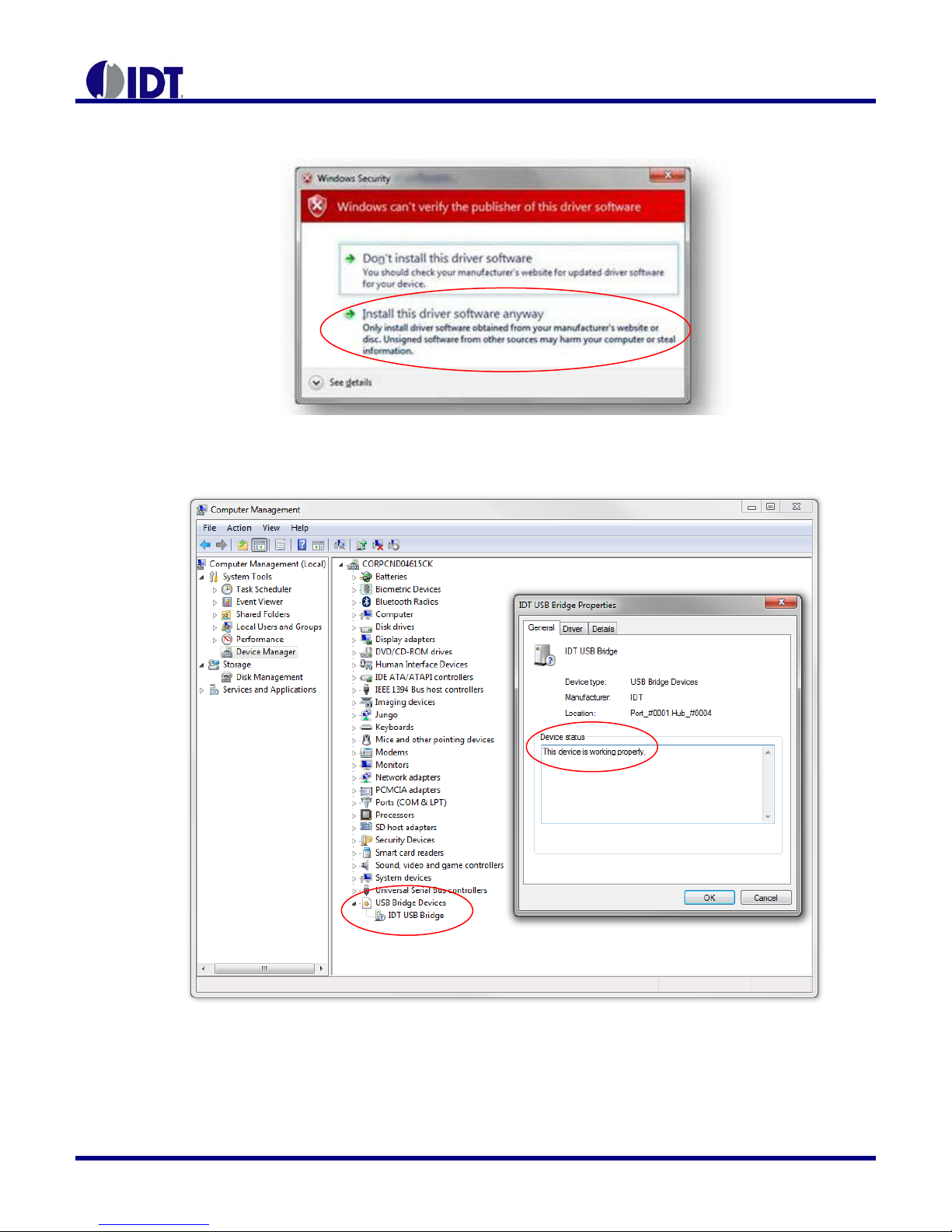
5. Accept the Warning (IDT is currently certifying the driver with Microsoft™ to bypass the warning):
6. Verification of successful driver installation:
Page 5

USB-BRIDGEV2-EVAL
August 3, 2015 Rev. V2.0
5
© 2015 Integrated Device Technology, Inc.
Evaluation Board Manual
Windows Driver Installation for Windows 8
The first time the USB-BRIDGEV2-EVAL is used the Windows Drivers must be installed.
The installation of the Windows USB-to I2C-interface on a Windows 8 system is shown by the following steps. Additional
reference is available at How to install a driver that does not contain digital signature information in Windows 8?
1. Connect the USB-BRIDGEV2-EVAL without any target evaluation system connected to your PC via the USB cable
included. The computer will report an error message that the driver is not digitally-signed.
2. Hold Shift key while choose to restart the computer.
3. Windows will show options below. Select Troubleshoot, Advanced options, Startup Settings, Restart.
Page 6

USB-BRIDGEV2-EVAL
August 3, 2015 Rev. V2.0
6
© 2015 Integrated Device Technology, Inc.
Evaluation Board Manual
4. After the computer restarts, select option 7) Disable driver signature enforcement.
5. When Windows restarts, reconnect the USB-BRIDGEV2-EVAL without any target evaluation system connected to
your PC via the USB cable included. The computer will report that driver is not successfully installed. Use Device
Manager to update the driver.
a. Choose Update in the Device Manager or follow the instructions for a new device found after first connecting
the interface.
b. Browse manually for the driver location:
Page 7

USB-BRIDGEV2-EVAL
August 3, 2015 Rev. V2.0
7
© 2015 Integrated Device Technology, Inc.
Step 5d
Evaluation Board Manual
c. Choose “Have a Disk” and select the “idt_usb_bridge.inf” from the uncompressed driver folder.
d. The computer will alert that “Windows can't verify the publisher of this driver software”. Choose “Install this
driver software anyway” to accept the Warning (IDT is currently certifying the driver with Microsoft™ to
bypass the warning):
Page 8

USB-BRIDGEV2-EVAL
August 3, 2015 Rev. V2.0
8
© 2015 Integrated Device Technology, Inc.
Step 6
Evaluation Board Manual
6. Verification of successful driver installation. Once the driver is installed, running IDTP91xx-PMIC-GUI should show
that the device is connected.
Page 9

USB-BRIDGEV2-EVAL
August 3, 2015 Rev. V2.0
9
© 2015 Integrated Device Technology, Inc.
µC CON
Level
Shift A
Level
Shift B
1
.8V
LDO
5V-USB
DATA
USB
VPUP
JP1
JP2
JP3
10
1 (SCL)
2 (SDA)
7
9
6
3 Level
8
(Analog)
11-14 (5V GPIO)
5 (Tri-Level)
3-4 (5V PWM)
Evaluation Board Manual
Device Configuration
Figure 2, Board Configuration
The USB-BRIDGEV2-EVAL has to be configured for the target system used. The detailed requirement for the target system
can be found in the respective manual.
The configuration will adjust the voltage level of the 2 on board level shifters (including pull up resistors) to the required target
system level using JP1,2 and 3 highlighted in the figure above and below.
Option 1 (JP1 shorted, JP2,3 open) will provide a 1.8V (on board LDO) voltage level for the I2C interface and CON-7,8 pins.
Option 2 (JP2 shorted, JP1,3 open) will provide the USB 5V voltage level for the I2C interface and CON-7,8 pins.
Option 3 (JP3 shorted, JP1,2 open) will provide the VPUP voltage level for the I2C interface and CON-7,8 pins. VPUP is
provided through the CON interface connector and allows the target system to supply the desired voltage level.
Option 1 and 2 can be combined with JP3 shorted to provide the 1.8V or 5V to the target system.
or provide a voltage through VPUP with JP1 and JP2 shorted!
Figure 3, System Overview
Never short JP1 and JP2 the same time
WARNING:
Page 10

USB-BRIDGEV2-EVAL
Evaluation Board Manual
August 3, 2015 Rev. V2.0
10
© 2015 Integrated Device Technology, Inc.
Schematic
Page 11

USB-BRIDGEV2-EVAL
August 3, 2015 Rev. V2.0
11
© 2015 Integrated Device Technology, Inc.
USB-BRIDGEV2-EVAL
$100.00
0°C to +85°C
Box 14”x10”x2”
1
Evaluation Board Manual
Ordering Guide
Table 1. Ordering Summary
PART NUMBER PRICE AMBIENT TEMP.
RANGE
SHIPPING CARRIER QUANTITY
www.IDT.com
6024 Silver Creek Valley Road
San Jose, California 95138
Tel: 800-345-7015
DISCLAIMER Integrated Dev i c e Technology, Inc. (IDT) a nd its subsidi ar i es reserve the r i gh t to modify the products a nd/or specific at ions describe d herein at a ny ti me and at ID T’ s sole discret i on . A l l
informatio n in this docum ent, includi ng descripti ons of product features an d performance, is subject t o change with out notice. P erformance s pecifications and the oper ating paramet ers of the
described products are det ermined i n the i ndepende nt state and are n ot guar anteed to perfo rm the sam e way w hen inst alled in c ustom er produc ts. The informa tion cont ained her ein is provided
without r epresentation or w arranty of any kin d, whether express or implied, includi ng, but not limited t o, the suitability of IDT’s products f or any particular p urpose, an implied warranty of
merchantabi li ty, or n on-i nfri ngem en t o f the i nt el lect ual pr oper ty ri ght s of others. T hi s doc ume nt i s pr es ente d o nly as a guid e and does not c o nvey any li cens e un der i nt ell ect ual pr opert y ri ght s of I DT
or any third parti es. ID T’s produc ts ar e not inte nded for us e in li fe su pport s yst ems or sim ilar dev ices wher e the failur e or malfunction of an I DT pro duct c an be r eas onabl y ex pecte d to si gni ficantl y
affect the health or safety of users. Anyone using an IDT product in such a manner does so at their own risk, absent an express, written agreement by IDT.
Integrated D evice Tech nology, IDT and the IDT l ogo are regis tered tradem arks of IDT . Other tradem arks and s ervice marks used herei n, includin g protected nam es, logos and desi gns, are the
property of IDT or their respective third party owners.
© Copyright 2015. All rights reserved.
 Loading...