

Page 1

IDT Tsi578
Titl
Serial RapidIO Switch
User Manual
June 6, 2016
Page 2

Integrated Device Technology, Inc. (“IDT”) reserves the right to make changes to its products or specifications at any time, without notice, in order to improve design or
performance. IDT does not assume responsibility for use of any circuitry described herein other than the circuitry embodied in an IDT product. Disclosure of the information
herein does not convey a license or any other right, by implication or otherwise, in any patent, trademark, or other intellectual property right of IDT. IDT products may
contain errata which can affect product performance to a minor or immaterial degree. Current characterized errata will be made available upon request. Items identi fied
herein as “reserved” or “undefined” are reserved for future definition. IDT does not assume responsibility for conflicts or incompatibilities arising from the future definition
of such items. IDT products have not been designed, tested, or manufactured for use in, and thus are not warranted for, applications where the failure, malfunction, or
any inaccuracy in the application carries a risk of death, serious bodily injury, or damage to tangible property. Code examples provided herein by IDT are for illustrative
purposes only and should not be relied upon for developing applications. Any use of such code examples shall be at the user's sole risk.
Copyright © 2016 Integrated Device Technology, Inc.
All Rights Reserved.
The IDT logo is registered to Integrated Device Technology, Inc. IDT and CPS are trademarks of Integrated Device Technology, Inc.
GENERAL DISCLAIMER
Page 3

Contents
About this Document. . . . . . . . . . . . . . . . . . . . . . . . . . . . . . . . . . . . . . . . . . . . . . . . . . . . 17
Scope . . . . . . . . . . . . . . . . . . . . . . . . . . . . . . . . . . . . . . . . . . . . . . . . . . . . . . . . . . . . . . . . . . . . . . . . . . . . . . . . . . . . . . . . . 17
Document Conventions . . . . . . . . . . . . . . . . . . . . . . . . . . . . . . . . . . . . . . . . . . . . . . . . . . . . . . . . . . . . . . . . . . . . . . . . . . . 17
Revision History . . . . . . . . . . . . . . . . . . . . . . . . . . . . . . . . . . . . . . . . . . . . . . . . . . . . . . . . . . . . . . . . . . . . . . . . . . . . . . . . 18
1. Functional Overview . . . . . . . . . . . . . . . . . . . . . . . . . . . . . . . . . . . . . . . . . . . . . . . . 21
1.1 Overview . . . . . . . . . . . . . . . . . . . . . . . . . . . . . . . . . . . . . . . . . . . . . . . . . . . . . . . . . . . . . . . . . . . . . . . . . . . . . . . . 21
1.1.1 Features . . . . . . . . . . . . . . . . . . . . . . . . . . . . . . . . . . . . . . . . . . . . . . . . . . . . . . . . . . . . . . . . . . . . . . . . . 24
1.2 Serial RapidIO Interface . . . . . . . . . . . . . . . . . . . . . . . . . . . . . . . . . . . . . . . . . . . . . . . . . . . . . . . . . . . . . . . . . . . . 26
1.2.1 Features . . . . . . . . . . . . . . . . . . . . . . . . . . . . . . . . . . . . . . . . . . . . . . . . . . . . . . . . . . . . . . . . . . . . . . . . . 26
1.2.2 Transaction Flow Overview. . . . . . . . . . . . . . . . . . . . . . . . . . . . . . . . . . . . . . . . . . . . . . . . . . . . . . . . . . 26
1.2.3 Maintenance Requests . . . . . . . . . . . . . . . . . . . . . . . . . . . . . . . . . . . . . . . . . . . . . . . . . . . . . . . . . . . . . . 27
1.2.4 Control Symbols. . . . . . . . . . . . . . . . . . . . . . . . . . . . . . . . . . . . . . . . . . . . . . . . . . . . . . . . . . . . . . . . . . . 27
1.3 Multicast Engine . . . . . . . . . . . . . . . . . . . . . . . . . . . . . . . . . . . . . . . . . . . . . . . . . . . . . . . . . . . . . . . . . . . . . . . . . . 27
1.3.1 Multicast Operation . . . . . . . . . . . . . . . . . . . . . . . . . . . . . . . . . . . . . . . . . . . . . . . . . . . . . . . . . . . . . . . . 27
1.3.2 Features . . . . . . . . . . . . . . . . . . . . . . . . . . . . . . . . . . . . . . . . . . . . . . . . . . . . . . . . . . . . . . . . . . . . . . . . . 28
1.4 Serial RapidIO Electrical Interface . . . . . . . . . . . . . . . . . . . . . . . . . . . . . . . . . . . . . . . . . . . . . . . . . . . . . . . . . . . . 28
1.5 Internal Switching Fabric (ISF) . . . . . . . . . . . . . . . . . . . . . . . . . . . . . . . . . . . . . . . . . . . . . . . . . . . . . . . . . . . . . . . 30
1.6 Internal Register Bus (AHB) . . . . . . . . . . . . . . . . . . . . . . . . . . . . . . . . . . . . . . . . . . . . . . . . . . . . . . . . . . . . . . . . . 30
1.7 I
1.8 JTAG Interface. . . . . . . . . . . . . . . . . . . . . . . . . . . . . . . . . . . . . . . . . . . . . . . . . . . . . . . . . . . . . . . . . . . . . . . . . . . . 32
2
C Interface. . . . . . . . . . . . . . . . . . . . . . . . . . . . . . . . . . . . . . . . . . . . . . . . . . . . . . . . . . . . . . . . . . . . . . . . . . . . . . 30
3
2. Serial RapidIO Interface. . . . . . . . . . . . . . . . . . . . . . . . . . . . . . . . . . . . . . . . . . . . . . 35
2.1 Overview . . . . . . . . . . . . . . . . . . . . . . . . . . . . . . . . . . . . . . . . . . . . . . . . . . . . . . . . . . . . . . . . . . . . . . . . . . . . . . . . 35
2.1.1 Features . . . . . . . . . . . . . . . . . . . . . . . . . . . . . . . . . . . . . . . . . . . . . . . . . . . . . . . . . . . . . . . . . . . . . . . . . 35
2.1.2 Transaction Flow Overview. . . . . . . . . . . . . . . . . . . . . . . . . . . . . . . . . . . . . . . . . . . . . . . . . . . . . . . . . . 36
2.1.3 Maintenance Requests . . . . . . . . . . . . . . . . . . . . . . . . . . . . . . . . . . . . . . . . . . . . . . . . . . . . . . . . . . . . . . 36
2.1.4 Control Symbols. . . . . . . . . . . . . . . . . . . . . . . . . . . . . . . . . . . . . . . . . . . . . . . . . . . . . . . . . . . . . . . . . . . 36
2.2 Transaction Flow . . . . . . . . . . . . . . . . . . . . . . . . . . . . . . . . . . . . . . . . . . . . . . . . . . . . . . . . . . . . . . . . . . . . . . . . . . 37
2.3 Lookup Tables . . . . . . . . . . . . . . . . . . . . . . . . . . . . . . . . . . . . . . . . . . . . . . . . . . . . . . . . . . . . . . . . . . . . . . . . . . . . 37
2.3.1 Filling the Lookup Tables . . . . . . . . . . . . . . . . . . . . . . . . . . . . . . . . . . . . . . . . . . . . . . . . . . . . . . . . . . . 38
2.3.2 LUT Modes . . . . . . . . . . . . . . . . . . . . . . . . . . . . . . . . . . . . . . . . . . . . . . . . . . . . . . . . . . . . . . . . . . . . . . 40
2.3.3 Flat Mode. . . . . . . . . . . . . . . . . . . . . . . . . . . . . . . . . . . . . . . . . . . . . . . . . . . . . . . . . . . . . . . . . . . . . . . . 40
2.3.4 Hierarchical Mode . . . . . . . . . . . . . . . . . . . . . . . . . . . . . . . . . . . . . . . . . . . . . . . . . . . . . . . . . . . . . . . . . 45
2.3.5 Mixed Mode of Operation . . . . . . . . . . . . . . . . . . . . . . . . . . . . . . . . . . . . . . . . . . . . . . . . . . . . . . . . . . . 49
2.3.6 Lookup Table Parity. . . . . . . . . . . . . . . . . . . . . . . . . . . . . . . . . . . . . . . . . . . . . . . . . . . . . . . . . . . . . . . . 49
2.3.7 Lookup Table Error Summary . . . . . . . . . . . . . . . . . . . . . . . . . . . . . . . . . . . . . . . . . . . . . . . . . . . . . . . . 50
2.3.8 Lookup Table Entry States. . . . . . . . . . . . . . . . . . . . . . . . . . . . . . . . . . . . . . . . . . . . . . . . . . . . . . . . . . . 51
2.4 Maintenance Packets . . . . . . . . . . . . . . . . . . . . . . . . . . . . . . . . . . . . . . . . . . . . . . . . . . . . . . . . . . . . . . . . . . . . . . . 53
2.5 Multicast Event Control Symbols . . . . . . . . . . . . . . . . . . . . . . . . . . . . . . . . . . . . . . . . . . . . . . . . . . . . . . . . . . . . . 55
2.5.1 MCS Reception . . . . . . . . . . . . . . . . . . . . . . . . . . . . . . . . . . . . . . . . . . . . . . . . . . . . . . . . . . . . . . . . . . . 55
2.5.2 Generating an MCS . . . . . . . . . . . . . . . . . . . . . . . . . . . . . . . . . . . . . . . . . . . . . . . . . . . . . . . . . . . . . . . . 56
2.5.3 Restrictions. . . . . . . . . . . . . . . . . . . . . . . . . . . . . . . . . . . . . . . . . . . . . . . . . . . . . . . . . . . . . . . . . . . . . . . 56
2.6 Reset Control Symbol Processing . . . . . . . . . . . . . . . . . . . . . . . . . . . . . . . . . . . . . . . . . . . . . . . . . . . . . . . . . . . . . 57
Integrated Device Technology
www.idt.com
Tsi578 User Manual
June 6, 2016
Page 4

Contents4
2.7 Data Integrity Checking. . . . . . . . . . . . . . . . . . . . . . . . . . . . . . . . . . . . . . . . . . . . . . . . . . . . . . . . . . . . . . . . . . . . . 57
2.7.1 Packet Data Integrity Checking. . . . . . . . . . . . . . . . . . . . . . . . . . . . . . . . . . . . . . . . . . . . . . . . . . . . . . . 57
2.7.2 Control Symbol Data Integrity Checking . . . . . . . . . . . . . . . . . . . . . . . . . . . . . . . . . . . . . . . . . . . . . . . 57
2.8 Error Management. . . . . . . . . . . . . . . . . . . . . . . . . . . . . . . . . . . . . . . . . . . . . . . . . . . . . . . . . . . . . . . . . . . . . . . . . 57
2.8.1 Software Assisted Error Recovery. . . . . . . . . . . . . . . . . . . . . . . . . . . . . . . . . . . . . . . . . . . . . . . . . . . . . 58
2.9 Hot Insertion and Hot Extraction. . . . . . . . . . . . . . . . . . . . . . . . . . . . . . . . . . . . . . . . . . . . . . . . . . . . . . . . . . . . . . 59
2.9.1 Hot Insertion . . . . . . . . . . . . . . . . . . . . . . . . . . . . . . . . . . . . . . . . . . . . . . . . . . . . . . . . . . . . . . . . . . . . . 60
2.9.2 Hot Extraction . . . . . . . . . . . . . . . . . . . . . . . . . . . . . . . . . . . . . . . . . . . . . . . . . . . . . . . . . . . . . . . . . . . . 61
2.9.3 Hot Extraction System Notification. . . . . . . . . . . . . . . . . . . . . . . . . . . . . . . . . . . . . . . . . . . . . . . . . . . . 62
2.10 Loss of Lane Synchronization . . . . . . . . . . . . . . . . . . . . . . . . . . . . . . . . . . . . . . . . . . . . . . . . . . . . . . . . . . . . . . . . 62
2.10.1 Dead Link Timer . . . . . . . . . . . . . . . . . . . . . . . . . . . . . . . . . . . . . . . . . . . . . . . . . . . . . . . . . . . . . . . . . . 64
2.10.2 Lane Sync Timer . . . . . . . . . . . . . . . . . . . . . . . . . . . . . . . . . . . . . . . . . . . . . . . . . . . . . . . . . . . . . . . . . . 64
3. Serial RapidIO Electrical Interface . . . . . . . . . . . . . . . . . . . . . . . . . . . . . . . . . . . . . .65
3.1 Overview . . . . . . . . . . . . . . . . . . . . . . . . . . . . . . . . . . . . . . . . . . . . . . . . . . . . . . . . . . . . . . . . . . . . . . . . . . . . . . . . 65
3.2 Port Numbering . . . . . . . . . . . . . . . . . . . . . . . . . . . . . . . . . . . . . . . . . . . . . . . . . . . . . . . . . . . . . . . . . . . . . . . . . . . 67
3.2.1 Port Configuration. . . . . . . . . . . . . . . . . . . . . . . . . . . . . . . . . . . . . . . . . . . . . . . . . . . . . . . . . . . . . . . . . 67
3.3 Port Aggregation: 1x and 4x Modes . . . . . . . . . . . . . . . . . . . . . . . . . . . . . . . . . . . . . . . . . . . . . . . . . . . . . . . . . . . 68
3.3.1 1x + 1x Configuration . . . . . . . . . . . . . . . . . . . . . . . . . . . . . . . . . . . . . . . . . . . . . . . . . . . . . . . . . . . . . . 69
3.3.2 4x Configuration . . . . . . . . . . . . . . . . . . . . . . . . . . . . . . . . . . . . . . . . . . . . . . . . . . . . . . . . . . . . . . . . . . 69
3.4 Clocking. . . . . . . . . . . . . . . . . . . . . . . . . . . . . . . . . . . . . . . . . . . . . . . . . . . . . . . . . . . . . . . . . . . . . . . . . . . . . . . . . 70
3.4.1 Changing the Clock Speed. . . . . . . . . . . . . . . . . . . . . . . . . . . . . . . . . . . . . . . . . . . . . . . . . . . . . . . . . . . 71
3.4.2 Changing the Clock Speed Through I
3.5 Port Power Down. . . . . . . . . . . . . . . . . . . . . . . . . . . . . . . . . . . . . . . . . . . . . . . . . . . . . . . . . . . . . . . . . . . . . . . . . . 72
3.5.1 Default Configurations on Power Down . . . . . . . . . . . . . . . . . . . . . . . . . . . . . . . . . . . . . . . . . . . . . . . . 72
3.5.2 Special Conditions for Port 0 Power Down. . . . . . . . . . . . . . . . . . . . . . . . . . . . . . . . . . . . . . . . . . . . . . 73
3.5.3 Power-Down Options . . . . . . . . . . . . . . . . . . . . . . . . . . . . . . . . . . . . . . . . . . . . . . . . . . . . . . . . . . . . . . 73
3.5.4 Configuration and Operation Through Power-down. . . . . . . . . . . . . . . . . . . . . . . . . . . . . . . . . . . . . . . 73
3.6 Port Lanes . . . . . . . . . . . . . . . . . . . . . . . . . . . . . . . . . . . . . . . . . . . . . . . . . . . . . . . . . . . . . . . . . . . . . . . . . . . . . . . 74
3.6.1 Lane Synchronization and Alignment . . . . . . . . . . . . . . . . . . . . . . . . . . . . . . . . . . . . . . . . . . . . . . . . . . 75
3.6.2 Lane Swapping . . . . . . . . . . . . . . . . . . . . . . . . . . . . . . . . . . . . . . . . . . . . . . . . . . . . . . . . . . . . . . . . . . . 75
3.7 Programmable Transmit and Receive Equalization. . . . . . . . . . . . . . . . . . . . . . . . . . . . . . . . . . . . . . . . . . . . . . . . 77
3.7.1 Transmit Drive Level and Equalization. . . . . . . . . . . . . . . . . . . . . . . . . . . . . . . . . . . . . . . . . . . . . . . . . 77
3.7.2 Receive Equalization . . . . . . . . . . . . . . . . . . . . . . . . . . . . . . . . . . . . . . . . . . . . . . . . . . . . . . . . . . . . . . . 78
3.8 Port Loopback Testing. . . . . . . . . . . . . . . . . . . . . . . . . . . . . . . . . . . . . . . . . . . . . . . . . . . . . . . . . . . . . . . . . . . . . . 79
3.8.1 Digital Equipment Loopback. . . . . . . . . . . . . . . . . . . . . . . . . . . . . . . . . . . . . . . . . . . . . . . . . . . . . . . . . 80
3.8.2 Logical Line Loopback . . . . . . . . . . . . . . . . . . . . . . . . . . . . . . . . . . . . . . . . . . . . . . . . . . . . . . . . . . . . . 80
3.9 Bit Error Rate Testing (BERT) . . . . . . . . . . . . . . . . . . . . . . . . . . . . . . . . . . . . . . . . . . . . . . . . . . . . . . . . . . . . . . . 80
3.9.1 BERT Pattern Generator . . . . . . . . . . . . . . . . . . . . . . . . . . . . . . . . . . . . . . . . . . . . . . . . . . . . . . . . . . . . 80
3.9.2 BERT Pattern Matcher and Error Counter. . . . . . . . . . . . . . . . . . . . . . . . . . . . . . . . . . . . . . . . . . . . . . . 82
3.9.3 Fixed Pattern-based BERT. . . . . . . . . . . . . . . . . . . . . . . . . . . . . . . . . . . . . . . . . . . . . . . . . . . . . . . . . . . 82
3.9.4 Using PRBS Scripts for the Transmitters and Receivers. . . . . . . . . . . . . . . . . . . . . . . . . . . . . . . . . . . . 83
2
C . . . . . . . . . . . . . . . . . . . . . . . . . . . . . . . . . . . . . . . . . . . . . . . . 71
4. Internal Switching Fabric . . . . . . . . . . . . . . . . . . . . . . . . . . . . . . . . . . . . . . . . . . . . .85
4.1 Overview . . . . . . . . . . . . . . . . . . . . . . . . . . . . . . . . . . . . . . . . . . . . . . . . . . . . . . . . . . . . . . . . . . . . . . . . . . . . . . . . 85
4.2 Functional Behavior. . . . . . . . . . . . . . . . . . . . . . . . . . . . . . . . . . . . . . . . . . . . . . . . . . . . . . . . . . . . . . . . . . . . . . . . 86
4.2.1 Transfer Modes . . . . . . . . . . . . . . . . . . . . . . . . . . . . . . . . . . . . . . . . . . . . . . . . . . . . . . . . . . . . . . . . . . . 87
Tsi578 User Manual
June 6, 2016
Integrated Device Technology
www.idt.com
Page 5

Contents 5
4.3 Arbitration for Egress Port. . . . . . . . . . . . . . . . . . . . . . . . . . . . . . . . . . . . . . . . . . . . . . . . . . . . . . . . . . . . . . . . . . . 88
4.3.1 Strict Priority Arbitration. . . . . . . . . . . . . . . . . . . . . . . . . . . . . . . . . . . . . . . . . . . . . . . . . . . . . . . . . . . . 88
4.3.2 Weighted Round Robin (WRR) Arbitration. . . . . . . . . . . . . . . . . . . . . . . . . . . . . . . . . . . . . . . . . . . . . . 89
4.4 Packet Queuing . . . . . . . . . . . . . . . . . . . . . . . . . . . . . . . . . . . . . . . . . . . . . . . . . . . . . . . . . . . . . . . . . . . . . . . . . . . 91
4.4.1 Output Queuing on the Egress Port . . . . . . . . . . . . . . . . . . . . . . . . . . . . . . . . . . . . . . . . . . . . . . . . . . . . 91
4.4.2 Input Queue for the ISF Port . . . . . . . . . . . . . . . . . . . . . . . . . . . . . . . . . . . . . . . . . . . . . . . . . . . . . . . . . 94
4.4.3 Input Arbitration. . . . . . . . . . . . . . . . . . . . . . . . . . . . . . . . . . . . . . . . . . . . . . . . . . . . . . . . . . . . . . . . . . . 95
4.4.4 Input Queuing Model for the Multicast Work Queue . . . . . . . . . . . . . . . . . . . . . . . . . . . . . . . . . . . . . . 99
4.4.5 Input Queuing Model for the Broadcast Buffer. . . . . . . . . . . . . . . . . . . . . . . . . . . . . . . . . . . . . . . . . . 100
4.4.6 Output Queuing Model for Multicast. . . . . . . . . . . . . . . . . . . . . . . . . . . . . . . . . . . . . . . . . . . . . . . . . . 100
4.4.7 ISF Bandwidth . . . . . . . . . . . . . . . . . . . . . . . . . . . . . . . . . . . . . . . . . . . . . . . . . . . . . . . . . . . . . . . . . . . 100
5. Multicast . . . . . . . . . . . . . . . . . . . . . . . . . . . . . . . . . . . . . . . . . . . . . . . . . . . . . . . . . 103
5.1 Overview . . . . . . . . . . . . . . . . . . . . . . . . . . . . . . . . . . . . . . . . . . . . . . . . . . . . . . . . . . . . . . . . . . . . . . . . . . . . . . . 103
5.1.1 Multicast Operation . . . . . . . . . . . . . . . . . . . . . . . . . . . . . . . . . . . . . . . . . . . . . . . . . . . . . . . . . . . . . . . 103
5.1.2 Features . . . . . . . . . . . . . . . . . . . . . . . . . . . . . . . . . . . . . . . . . . . . . . . . . . . . . . . . . . . . . . . . . . . . . . . . 103
5.1.3 Multicast Operation with Multiple Tsi57x Switches . . . . . . . . . . . . . . . . . . . . . . . . . . . . . . . . . . . . . . 104
5.1.4 Multicast Terminology. . . . . . . . . . . . . . . . . . . . . . . . . . . . . . . . . . . . . . . . . . . . . . . . . . . . . . . . . . . . . 105
5.1.5 Multicast Behavior Overview . . . . . . . . . . . . . . . . . . . . . . . . . . . . . . . . . . . . . . . . . . . . . . . . . . . . . . . 106
5.1.6 Multicast Work Queue . . . . . . . . . . . . . . . . . . . . . . . . . . . . . . . . . . . . . . . . . . . . . . . . . . . . . . . . . . . . . 107
5.1.7 Broadcast Buffers. . . . . . . . . . . . . . . . . . . . . . . . . . . . . . . . . . . . . . . . . . . . . . . . . . . . . . . . . . . . . . . . . 107
5.2 Multicast Group Tables . . . . . . . . . . . . . . . . . . . . . . . . . . . . . . . . . . . . . . . . . . . . . . . . . . . . . . . . . . . . . . . . . . . . 110
5.2.1 Configuring Basic Associations. . . . . . . . . . . . . . . . . . . . . . . . . . . . . . . . . . . . . . . . . . . . . . . . . . . . . . 112
5.2.2 Configuring Multicast Masks. . . . . . . . . . . . . . . . . . . . . . . . . . . . . . . . . . . . . . . . . . . . . . . . . . . . . . . . 113
5.2.3 Configuring Multicast Masks Using the IDT Specific Registers. . . . . . . . . . . . . . . . . . . . . . . . . . . . . 116
5.3 Arbitration for Multicast Engine Ingress Port . . . . . . . . . . . . . . . . . . . . . . . . . . . . . . . . . . . . . . . . . . . . . . . . . . . 117
5.4 Error Management of Multicast Packets . . . . . . . . . . . . . . . . . . . . . . . . . . . . . . . . . . . . . . . . . . . . . . . . . . . . . . . 118
5.4.1 Packet TEA . . . . . . . . . . . . . . . . . . . . . . . . . . . . . . . . . . . . . . . . . . . . . . . . . . . . . . . . . . . . . . . . . . . . . 118
5.4.2 Multicast Packet Stomping. . . . . . . . . . . . . . . . . . . . . . . . . . . . . . . . . . . . . . . . . . . . . . . . . . . . . . . . . . 118
5.4.3 Multicast Maximum Latency Timer. . . . . . . . . . . . . . . . . . . . . . . . . . . . . . . . . . . . . . . . . . . . . . . . . . . 119
5.4.4 Silent Discard of Packets . . . . . . . . . . . . . . . . . . . . . . . . . . . . . . . . . . . . . . . . . . . . . . . . . . . . . . . . . . . 120
5.4.5 Port-writes and Multicast. . . . . . . . . . . . . . . . . . . . . . . . . . . . . . . . . . . . . . . . . . . . . . . . . . . . . . . . . . . 120
5.5 Port Reset. . . . . . . . . . . . . . . . . . . . . . . . . . . . . . . . . . . . . . . . . . . . . . . . . . . . . . . . . . . . . . . . . . . . . . . . . . . . . . . 120
6. Event Notification. . . . . . . . . . . . . . . . . . . . . . . . . . . . . . . . . . . . . . . . . . . . . . . . . . 121
6.1 Overview . . . . . . . . . . . . . . . . . . . . . . . . . . . . . . . . . . . . . . . . . . . . . . . . . . . . . . . . . . . . . . . . . . . . . . . . . . . . . . . 121
6.2 Event Summary . . . . . . . . . . . . . . . . . . . . . . . . . . . . . . . . . . . . . . . . . . . . . . . . . . . . . . . . . . . . . . . . . . . . . . . . . . 122
6.3 Error Rate Thresholds . . . . . . . . . . . . . . . . . . . . . . . . . . . . . . . . . . . . . . . . . . . . . . . . . . . . . . . . . . . . . . . . . . . . . 126
6.3.1 Maintaining Packet Flow . . . . . . . . . . . . . . . . . . . . . . . . . . . . . . . . . . . . . . . . . . . . . . . . . . . . . . . . . . . 127
6.4 Error Stopped State Recovery . . . . . . . . . . . . . . . . . . . . . . . . . . . . . . . . . . . . . . . . . . . . . . . . . . . . . . . . . . . . . . . 128
6.4.1 Error Stopped States. . . . . . . . . . . . . . . . . . . . . . . . . . . . . . . . . . . . . . . . . . . . . . . . . . . . . . . . . . . . . . . 128
6.4.2 Link Error Clearing and Recovery. . . . . . . . . . . . . . . . . . . . . . . . . . . . . . . . . . . . . . . . . . . . . . . . . . . . 129
6.5 Event Capture. . . . . . . . . . . . . . . . . . . . . . . . . . . . . . . . . . . . . . . . . . . . . . . . . . . . . . . . . . . . . . . . . . . . . . . . . . . . 131
6.6 Port-write Notifications . . . . . . . . . . . . . . . . . . . . . . . . . . . . . . . . . . . . . . . . . . . . . . . . . . . . . . . . . . . . . . . . . . . . 133
6.6.1 Destination ID . . . . . . . . . . . . . . . . . . . . . . . . . . . . . . . . . . . . . . . . . . . . . . . . . . . . . . . . . . . . . . . . . . . 134
6.6.2 Payload. . . . . . . . . . . . . . . . . . . . . . . . . . . . . . . . . . . . . . . . . . . . . . . . . . . . . . . . . . . . . . . . . . . . . . . . . 134
6.6.3 Servicing Port-writes . . . . . . . . . . . . . . . . . . . . . . . . . . . . . . . . . . . . . . . . . . . . . . . . . . . . . . . . . . . . . . 135
Integrated Device Technology
www.idt.com
Tsi578 User Manual
June 6, 2016
Page 6

Contents6
6.6.4 Port-writes and Hot Insertion/Hot Extraction Notification . . . . . . . . . . . . . . . . . . . . . . . . . . . . . . . . . 136
6.6.5 Port-writes and Multicast. . . . . . . . . . . . . . . . . . . . . . . . . . . . . . . . . . . . . . . . . . . . . . . . . . . . . . . . . . . 136
6.7 Interrupt Notifications . . . . . . . . . . . . . . . . . . . . . . . . . . . . . . . . . . . . . . . . . . . . . . . . . . . . . . . . . . . . . . . . . . . . . 136
6.7.1 INT_b Signal . . . . . . . . . . . . . . . . . . . . . . . . . . . . . . . . . . . . . . . . . . . . . . . . . . . . . . . . . . . . . . . . . . . . 138
6.7.2 Global Interrupt Status Register and Interrupt Handling . . . . . . . . . . . . . . . . . . . . . . . . . . . . . . . . . . . 138
6.7.3 Interrupt Notification and Port-writes . . . . . . . . . . . . . . . . . . . . . . . . . . . . . . . . . . . . . . . . . . . . . . . . . 140
6.7.4 Reset Control Symbol and Interrupt Handling . . . . . . . . . . . . . . . . . . . . . . . . . . . . . . . . . . . . . . . . . . 140
7. I2C Interface . . . . . . . . . . . . . . . . . . . . . . . . . . . . . . . . . . . . . . . . . . . . . . . . . . . . . . .141
7.1 Overview . . . . . . . . . . . . . . . . . . . . . . . . . . . . . . . . . . . . . . . . . . . . . . . . . . . . . . . . . . . . . . . . . . . . . . . . . . . . . . . 141
7.2 Protocol Overview. . . . . . . . . . . . . . . . . . . . . . . . . . . . . . . . . . . . . . . . . . . . . . . . . . . . . . . . . . . . . . . . . . . . . . . . 143
7.3 Block Diagram. . . . . . . . . . . . . . . . . . . . . . . . . . . . . . . . . . . . . . . . . . . . . . . . . . . . . . . . . . . . . . . . . . . . . . . . . . . 144
7.4 Tsi578 as I
7.4.1 Example EEPROM Read and Write . . . . . . . . . . . . . . . . . . . . . . . . . . . . . . . . . . . . . . . . . . . . . . . . . . 149
7.4.2 Master Clock Generation. . . . . . . . . . . . . . . . . . . . . . . . . . . . . . . . . . . . . . . . . . . . . . . . . . . . . . . . . . . 149
7.4.3 Master Bus Arbitration . . . . . . . . . . . . . . . . . . . . . . . . . . . . . . . . . . . . . . . . . . . . . . . . . . . . . . . . . . . . 150
7.4.4 Master External Device Addressing . . . . . . . . . . . . . . . . . . . . . . . . . . . . . . . . . . . . . . . . . . . . . . . . . . 150
7.4.5 Master Peripheral Addressing . . . . . . . . . . . . . . . . . . . . . . . . . . . . . . . . . . . . . . . . . . . . . . . . . . . . . . . 150
7.4.6 Master Data Transactions . . . . . . . . . . . . . . . . . . . . . . . . . . . . . . . . . . . . . . . . . . . . . . . . . . . . . . . . . . 151
7.5 Tsi578 as I
7.5.1 Slave Clock Stretching. . . . . . . . . . . . . . . . . . . . . . . . . . . . . . . . . . . . . . . . . . . . . . . . . . . . . . . . . . . . . 153
7.5.2 Slave Device Addressing. . . . . . . . . . . . . . . . . . . . . . . . . . . . . . . . . . . . . . . . . . . . . . . . . . . . . . . . . . . 154
7.5.3 Slave Peripheral Addressing . . . . . . . . . . . . . . . . . . . . . . . . . . . . . . . . . . . . . . . . . . . . . . . . . . . . . . . . 154
7.5.4 External I
7.5.5 Slave Write Data Transactions. . . . . . . . . . . . . . . . . . . . . . . . . . . . . . . . . . . . . . . . . . . . . . . . . . . . . . . 156
7.5.6 Slave Read Data Transactions . . . . . . . . . . . . . . . . . . . . . . . . . . . . . . . . . . . . . . . . . . . . . . . . . . . . . . . 157
7.5.7 Slave Internal Register Accesses. . . . . . . . . . . . . . . . . . . . . . . . . . . . . . . . . . . . . . . . . . . . . . . . . . . . . 157
7.5.8 Slave Access Examples . . . . . . . . . . . . . . . . . . . . . . . . . . . . . . . . . . . . . . . . . . . . . . . . . . . . . . . . . . . . 158
7.5.9 Resetting the I
7.6 Mailboxes. . . . . . . . . . . . . . . . . . . . . . . . . . . . . . . . . . . . . . . . . . . . . . . . . . . . . . . . . . . . . . . . . . . . . . . . . . . . . . . 161
7.6.1 Incoming Mailbox . . . . . . . . . . . . . . . . . . . . . . . . . . . . . . . . . . . . . . . . . . . . . . . . . . . . . . . . . . . . . . . . 163
7.6.2 Outgoing Mailbox . . . . . . . . . . . . . . . . . . . . . . . . . . . . . . . . . . . . . . . . . . . . . . . . . . . . . . . . . . . . . . . . 163
7.7 SMBus Support . . . . . . . . . . . . . . . . . . . . . . . . . . . . . . . . . . . . . . . . . . . . . . . . . . . . . . . . . . . . . . . . . . . . . . . . . . 163
7.7.1 Unsupported SMBus Features. . . . . . . . . . . . . . . . . . . . . . . . . . . . . . . . . . . . . . . . . . . . . . . . . . . . . . . 1 6 4
7.7.2 SMBus Protocol Support. . . . . . . . . . . . . . . . . . . . . . . . . . . . . . . . . . . . . . . . . . . . . . . . . . . . . . . . . . . 164
7.7.3 SMBus Alert Response Protocol Support . . . . . . . . . . . . . . . . . . . . . . . . . . . . . . . . . . . . . . . . . . . . . . 166
7.8 Boot Load Sequence . . . . . . . . . . . . . . . . . . . . . . . . . . . . . . . . . . . . . . . . . . . . . . . . . . . . . . . . . . . . . . . . . . . . . . 166
7.8.1 Idle Detect . . . . . . . . . . . . . . . . . . . . . . . . . . . . . . . . . . . . . . . . . . . . . . . . . . . . . . . . . . . . . . . . . . . . . . 168
7.8.2 EEPROM Reset Sequence. . . . . . . . . . . . . . . . . . . . . . . . . . . . . . . . . . . . . . . . . . . . . . . . . . . . . . . . . . 1 6 8
7.8.3 Wait for Bus Idle . . . . . . . . . . . . . . . . . . . . . . . . . . . . . . . . . . . . . . . . . . . . . . . . . . . . . . . . . . . . . . . . . 168
7.8.4 EEPROM Device Detection . . . . . . . . . . . . . . . . . . . . . . . . . . . . . . . . . . . . . . . . . . . . . . . . . . . . . . . . 169
7.8.5 Loading Register Data from EEPROM. . . . . . . . . . . . . . . . . . . . . . . . . . . . . . . . . . . . . . . . . . . . . . . . 169
7.8.6 Chaining. . . . . . . . . . . . . . . . . . . . . . . . . . . . . . . . . . . . . . . . . . . . . . . . . . . . . . . . . . . . . . . . . . . . . . . . 170
7.8.7 EEPROM Data Format . . . . . . . . . . . . . . . . . . . . . . . . . . . . . . . . . . . . . . . . . . . . . . . . . . . . . . . . . . . . 170
7.8.8 I2C Boot Time. . . . . . . . . . . . . . . . . . . . . . . . . . . . . . . . . . . . . . . . . . . . . . . . . . . . . . . . . . . . . . . . . . . 172
7.8.9 Accelerating Boot Load. . . . . . . . . . . . . . . . . . . . . . . . . . . . . . . . . . . . . . . . . . . . . . . . . . . . . . . . . . . . 173
7.9 Error Handling. . . . . . . . . . . . . . . . . . . . . . . . . . . . . . . . . . . . . . . . . . . . . . . . . . . . . . . . . . . . . . . . . . . . . . . . . . . 174
2
C Master . . . . . . . . . . . . . . . . . . . . . . . . . . . . . . . . . . . . . . . . . . . . . . . . . . . . . . . . . . . . . . . . . . . . . . 147
2
C Slave . . . . . . . . . . . . . . . . . . . . . . . . . . . . . . . . . . . . . . . . . . . . . . . . . . . . . . . . . . . . . . . . . . . . . . . 151
2
C Register Map. . . . . . . . . . . . . . . . . . . . . . . . . . . . . . . . . . . . . . . . . . . . . . . . . . . . . . . . . . 155
2
C Slave Interface. . . . . . . . . . . . . . . . . . . . . . . . . . . . . . . . . . . . . . . . . . . . . . . . . . . . . 161
Tsi578 User Manual
June 6, 2016
Integrated Device Technology
www.idt.com
Page 7

Contents 7
7.10 Interrupt Handling . . . . . . . . . . . . . . . . . . . . . . . . . . . . . . . . . . . . . . . . . . . . . . . . . . . . . . . . . . . . . . . . . . . . . . . . 176
7.11 Events versus Interrupts. . . . . . . . . . . . . . . . . . . . . . . . . . . . . . . . . . . . . . . . . . . . . . . . . . . . . . . . . . . . . . . . . . . . 177
7.12 Timeouts. . . . . . . . . . . . . . . . . . . . . . . . . . . . . . . . . . . . . . . . . . . . . . . . . . . . . . . . . . . . . . . . . . . . . . . . . . . . . . . . 179
7.13 Bus Timing. . . . . . . . . . . . . . . . . . . . . . . . . . . . . . . . . . . . . . . . . . . . . . . . . . . . . . . . . . . . . . . . . . . . . . . . . . . . . . 183
7.13.1 Start/Restart Condition Setup and Hold. . . . . . . . . . . . . . . . . . . . . . . . . . . . . . . . . . . . . . . . . . . . . . . . 185
7.13.2 Stop Condition Setup . . . . . . . . . . . . . . . . . . . . . . . . . . . . . . . . . . . . . . . . . . . . . . . . . . . . . . . . . . . . . . 185
7.13.3 I2C_SD Setup and Hold. . . . . . . . . . . . . . . . . . . . . . . . . . . . . . . . . . . . . . . . . . . . . . . . . . . . . . . . . . . . 185
7.13.4 I2C_SCLK Nominal and Minimum Periods . . . . . . . . . . . . . . . . . . . . . . . . . . . . . . . . . . . . . . . . . . . . 186
7.13.5 Idle Detect Period. . . . . . . . . . . . . . . . . . . . . . . . . . . . . . . . . . . . . . . . . . . . . . . . . . . . . . . . . . . . . . . . . 186
8. Performance . . . . . . . . . . . . . . . . . . . . . . . . . . . . . . . . . . . . . . . . . . . . . . . . . . . . . . 187
8.1 Overview . . . . . . . . . . . . . . . . . . . . . . . . . . . . . . . . . . . . . . . . . . . . . . . . . . . . . . . . . . . . . . . . . . . . . . . . . . . . . . . 187
8.1.1 Throughput. . . . . . . . . . . . . . . . . . . . . . . . . . . . . . . . . . . . . . . . . . . . . . . . . . . . . . . . . . . . . . . . . . . . . . 187
8.1.2 Latency. . . . . . . . . . . . . . . . . . . . . . . . . . . . . . . . . . . . . . . . . . . . . . . . . . . . . . . . . . . . . . . . . . . . . . . . . 187
8.2 Performance Monitoring . . . . . . . . . . . . . . . . . . . . . . . . . . . . . . . . . . . . . . . . . . . . . . . . . . . . . . . . . . . . . . . . . . . 188
8.2.1 Traffic Efficiency . . . . . . . . . . . . . . . . . . . . . . . . . . . . . . . . . . . . . . . . . . . . . . . . . . . . . . . . . . . . . . . . . 190
8.2.2 Throughput. . . . . . . . . . . . . . . . . . . . . . . . . . . . . . . . . . . . . . . . . . . . . . . . . . . . . . . . . . . . . . . . . . . . . . 190
8.2.3 Bottleneck Detection . . . . . . . . . . . . . . . . . . . . . . . . . . . . . . . . . . . . . . . . . . . . . . . . . . . . . . . . . . . . . . 191
8.2.4 Congestion Detection. . . . . . . . . . . . . . . . . . . . . . . . . . . . . . . . . . . . . . . . . . . . . . . . . . . . . . . . . . . . . . 191
8.2.5 Resetting Performance Registers . . . . . . . . . . . . . . . . . . . . . . . . . . . . . . . . . . . . . . . . . . . . . . . . . . . . . 191
8.3 Configuring the Tsi578 for Performance Measurements. . . . . . . . . . . . . . . . . . . . . . . . . . . . . . . . . . . . . . . . . . . 192
8.3.1 Clock Speeds . . . . . . . . . . . . . . . . . . . . . . . . . . . . . . . . . . . . . . . . . . . . . . . . . . . . . . . . . . . . . . . . . . . . 192
8.3.2 Tsi578 ISF Arbitration Settings . . . . . . . . . . . . . . . . . . . . . . . . . . . . . . . . . . . . . . . . . . . . . . . . . . . . . . 192
8.3.3 Tsi578 RapidIO Transmission Scheduler Settings. . . . . . . . . . . . . . . . . . . . . . . . . . . . . . . . . . . . . . . . 193
8.3.4 Tsi578 RapidIO Buffer Watermark Selection Settings . . . . . . . . . . . . . . . . . . . . . . . . . . . . . . . . . . . . 193
8.4 Port-to-Port Performance Characteristics . . . . . . . . . . . . . . . . . . . . . . . . . . . . . . . . . . . . . . . . . . . . . . . . . . . . . . 193
8.4.1 Port-to-Port Packet Latency Performance . . . . . . . . . . . . . . . . . . . . . . . . . . . . . . . . . . . . . . . . . . . . . . 193
8.4.2 Packet Throughput Performance . . . . . . . . . . . . . . . . . . . . . . . . . . . . . . . . . . . . . . . . . . . . . . . . . . . . . 194
8.4.3 Multicast Performance. . . . . . . . . . . . . . . . . . . . . . . . . . . . . . . . . . . . . . . . . . . . . . . . . . . . . . . . . . . . . 195
8.5 Congestion Detection and Management . . . . . . . . . . . . . . . . . . . . . . . . . . . . . . . . . . . . . . . . . . . . . . . . . . . . . . . 196
8.5.1 Congestion Registers . . . . . . . . . . . . . . . . . . . . . . . . . . . . . . . . . . . . . . . . . . . . . . . . . . . . . . . . . . . . . . 198
9. JTAG Interface . . . . . . . . . . . . . . . . . . . . . . . . . . . . . . . . . . . . . . . . . . . . . . . . . . . . 201
9.1 Overview . . . . . . . . . . . . . . . . . . . . . . . . . . . . . . . . . . . . . . . . . . . . . . . . . . . . . . . . . . . . . . . . . . . . . . . . . . . . . . . 201
9.2 JTAG Device Identification Number . . . . . . . . . . . . . . . . . . . . . . . . . . . . . . . . . . . . . . . . . . . . . . . . . . . . . . . . . . 202
9.3 JTAG Register Access Details. . . . . . . . . . . . . . . . . . . . . . . . . . . . . . . . . . . . . . . . . . . . . . . . . . . . . . . . . . . . . . . 202
9.3.1 Format . . . . . . . . . . . . . . . . . . . . . . . . . . . . . . . . . . . . . . . . . . . . . . . . . . . . . . . . . . . . . . . . . . . . . . . . . 202
9.3.2 Write Access to Registers from the JTAG Interface . . . . . . . . . . . . . . . . . . . . . . . . . . . . . . . . . . . . . . 203
9.3.3 Read Access to Registers from the JTAG Interface. . . . . . . . . . . . . . . . . . . . . . . . . . . . . . . . . . . . . . . 203
10. Clocks, Resets and Power-up Options. . . . . . . . . . . . . . . . . . . . . . . . . . . . . . . . . 205
10.1 Clocks. . . . . . . . . . . . . . . . . . . . . . . . . . . . . . . . . . . . . . . . . . . . . . . . . . . . . . . . . . . . . . . . . . . . . . . . . . . . . . . . . . 205
10.1.1 Clocking Architecture . . . . . . . . . . . . . . . . . . . . . . . . . . . . . . . . . . . . . . . . . . . . . . . . . . . . . . . . . . . . . 206
10.1.2 SerDes Clocks . . . . . . . . . . . . . . . . . . . . . . . . . . . . . . . . . . . . . . . . . . . . . . . . . . . . . . . . . . . . . . . . . . . 207
10.1.3 Reference clocks . . . . . . . . . . . . . . . . . . . . . . . . . . . . . . . . . . . . . . . . . . . . . . . . . . . . . . . . . . . . . . . . . 207
10.1.4 Clock Domains. . . . . . . . . . . . . . . . . . . . . . . . . . . . . . . . . . . . . . . . . . . . . . . . . . . . . . . . . . . . . . . . . . . 208
10.1.5 Clock Gating . . . . . . . . . . . . . . . . . . . . . . . . . . . . . . . . . . . . . . . . . . . . . . . . . . . . . . . . . . . . . . . . . . . . 208
Integrated Device Technology
www.idt.com
Tsi578 User Manual
June 6, 2016
Page 8

Contents8
10.2 Resets. . . . . . . . . . . . . . . . . . . . . . . . . . . . . . . . . . . . . . . . . . . . . . . . . . . . . . . . . . . . . . . . . . . . . . . . . . . . . . . . . . 209
10.2.1 Device Reset . . . . . . . . . . . . . . . . . . . . . . . . . . . . . . . . . . . . . . . . . . . . . . . . . . . . . . . . . . . . . . . . . . . . 209
10.2.2 Per-Port Reset . . . . . . . . . . . . . . . . . . . . . . . . . . . . . . . . . . . . . . . . . . . . . . . . . . . . . . . . . . . . . . . . . . . 211
10.2.3 Generating a RapidIO Reset Request to a Peer Device. . . . . . . . . . . . . . . . . . . . . . . . . . . . . . . . . . . . 211
10.2.4 JTAG Reset . . . . . . . . . . . . . . . . . . . . . . . . . . . . . . . . . . . . . . . . . . . . . . . . . . . . . . . . . . . . . . . . . . . . . 211
10.3 Power-up Options . . . . . . . . . . . . . . . . . . . . . . . . . . . . . . . . . . . . . . . . . . . . . . . . . . . . . . . . . . . . . . . . . . . . . . . . 212
10.3.1 Power-up Option Signals. . . . . . . . . . . . . . . . . . . . . . . . . . . . . . . . . . . . . . . . . . . . . . . . . . . . . . . . . . . 212
10.3.2 Default Port Speed. . . . . . . . . . . . . . . . . . . . . . . . . . . . . . . . . . . . . . . . . . . . . . . . . . . . . . . . . . . . . . . . 214
10.3.3 Port Power-up and Power-down . . . . . . . . . . . . . . . . . . . . . . . . . . . . . . . . . . . . . . . . . . . . . . . . . . . . . 214
10.3.4 Port Width Override. . . . . . . . . . . . . . . . . . . . . . . . . . . . . . . . . . . . . . . . . . . . . . . . . . . . . . . . . . . . . . . 214
11. Signals . . . . . . . . . . . . . . . . . . . . . . . . . . . . . . . . . . . . . . . . . . . . . . . . . . . . . . . . . . .215
11.1 Overview . . . . . . . . . . . . . . . . . . . . . . . . . . . . . . . . . . . . . . . . . . . . . . . . . . . . . . . . . . . . . . . . . . . . . . . . . . . . . . . 215
11.2 Endian Ordering. . . . . . . . . . . . . . . . . . . . . . . . . . . . . . . . . . . . . . . . . . . . . . . . . . . . . . . . . . . . . . . . . . . . . . . . . . 216
11.3 Port Numbering . . . . . . . . . . . . . . . . . . . . . . . . . . . . . . . . . . . . . . . . . . . . . . . . . . . . . . . . . . . . . . . . . . . . . . . . . . 216
11.4 Signal Groupings . . . . . . . . . . . . . . . . . . . . . . . . . . . . . . . . . . . . . . . . . . . . . . . . . . . . . . . . . . . . . . . . . . . . . . . . . 218
11.5 Pinlist and Ballmap . . . . . . . . . . . . . . . . . . . . . . . . . . . . . . . . . . . . . . . . . . . . . . . . . . . . . . . . . . . . . . . . . . . . . . . 227
12. Serial RapidIO Registers. . . . . . . . . . . . . . . . . . . . . . . . . . . . . . . . . . . . . . . . . . . . .229
12.1 Overview . . . . . . . . . . . . . . . . . . . . . . . . . . . . . . . . . . . . . . . . . . . . . . . . . . . . . . . . . . . . . . . . . . . . . . . . . . . . . . . 229
12.1.1 Reserved Register Addresses and Fields. . . . . . . . . . . . . . . . . . . . . . . . . . . . . . . . . . . . . . . . . . . . . . . 230
12.2 Port Numbering . . . . . . . . . . . . . . . . . . . . . . . . . . . . . . . . . . . . . . . . . . . . . . . . . . . . . . . . . . . . . . . . . . . . . . . . . . 231
12.3 Conventions . . . . . . . . . . . . . . . . . . . . . . . . . . . . . . . . . . . . . . . . . . . . . . . . . . . . . . . . . . . . . . . . . . . . . . . . . . . . . 231
12.4 Register Map . . . . . . . . . . . . . . . . . . . . . . . . . . . . . . . . . . . . . . . . . . . . . . . . . . . . . . . . . . . . . . . . . . . . . . . . . . . . 233
12.5 RapidIO Logical Layer and Transport Layer Registers. . . . . . . . . . . . . . . . . . . . . . . . . . . . . . . . . . . . . . . . . . . . 245
12.5.1 RapidIO Device Identity CAR. . . . . . . . . . . . . . . . . . . . . . . . . . . . . . . . . . . . . . . . . . . . . . . . . . . . . . . 246
12.5.2 RapidIO Device Information CAR . . . . . . . . . . . . . . . . . . . . . . . . . . . . . . . . . . . . . . . . . . . . . . . . . . . 247
12.5.3 RapidIO Assembly Identity CAR . . . . . . . . . . . . . . . . . . . . . . . . . . . . . . . . . . . . . . . . . . . . . . . . . . . . 248
12.5.4 RapidIO Assembly Information CAR. . . . . . . . . . . . . . . . . . . . . . . . . . . . . . . . . . . . . . . . . . . . . . . . . 249
12.5.5 RapidIO Processing Element Features CAR. . . . . . . . . . . . . . . . . . . . . . . . . . . . . . . . . . . . . . . . . . . . 250
12.5.6 RapidIO Switch Port Information CAR. . . . . . . . . . . . . . . . . . . . . . . . . . . . . . . . . . . . . . . . . . . . . . . . 252
12.5.7 RapidIO Source Operation CAR . . . . . . . . . . . . . . . . . . . . . . . . . . . . . . . . . . . . . . . . . . . . . . . . . . . . . 253
12.5.8 RapidIO Switch Multicast Support CAR . . . . . . . . . . . . . . . . . . . . . . . . . . . . . . . . . . . . . . . . . . . . . . 255
12.5.9 RapidIO Route LUT Size CAR. . . . . . . . . . . . . . . . . . . . . . . . . . . . . . . . . . . . . . . . . . . . . . . . . . . . . . 256
12.5.10 RapidIO Switch Multicast Information CAR . . . . . . . . . . . . . . . . . . . . . . . . . . . . . . . . . . . . . . . . . . . 257
12.5.11 RapidIO Host Base Device ID Lock CSR. . . . . . . . . . . . . . . . . . . . . . . . . . . . . . . . . . . . . . . . . . . . . . 258
12.5.12 RapidIO Component Tag CSR . . . . . . . . . . . . . . . . . . . . . . . . . . . . . . . . . . . . . . . . . . . . . . . . . . . . . . 259
12.5.13 RapidIO Route Configuration DestID CSR. . . . . . . . . . . . . . . . . . . . . . . . . . . . . . . . . . . . . . . . . . . . . 260
12.5.14 RapidIO Route Configuration Output Port CSR . . . . . . . . . . . . . . . . . . . . . . . . . . . . . . . . . . . . . . . . . 261
12.5.15 RapidIO Rou t e LUT A t tributes (Default Port) CSR . . . . . . . . . . . . . . . . . . . . . . . . . . . . . . . . . . . . . . 262
12.5.16 RapidIO Multicast Mask Configuration Register . . . . . . . . . . . . . . . . . . . . . . . . . . . . . . . . . . . . . . . . 263
12.5.17 RapidIO Multicast DestID Configuration Register . . . . . . . . . . . . . . . . . . . . . . . . . . . . . . . . . . . . . . . 265
12.5.18 RapidIO Multicast DestID Association Register. . . . . . . . . . . . . . . . . . . . . . . . . . . . . . . . . . . . . . . . . 266
12.6 RapidIO Physical Layer Registers. . . . . . . . . . . . . . . . . . . . . . . . . . . . . . . . . . . . . . . . . . . . . . . . . . . . . . . . . . . . 268
12.6.1 RapidIO 1x or 4x Switch Port Maintenance Block Header. . . . . . . . . . . . . . . . . . . . . . . . . . . . . . . . . 270
12.6.2 RapidIO Switch Port Link Timeout Control CSR. . . . . . . . . . . . . . . . . . . . . . . . . . . . . . . . . . . . . . . . 271
Tsi578 User Manual
June 6, 2016
Integrated Device Technology
www.idt.com
Page 9

Contents 9
12.6.3 RapidIO Switch Port General Control CSR. . . . . . . . . . . . . . . . . . . . . . . . . . . . . . . . . . . . . . . . . . . . . 272
12.6.4 RapidIO Serial Port x Link Maintenance Request CSR . . . . . . . . . . . . . . . . . . . . . . . . . . . . . . . . . . . 273
12.6.5 RapidIO Serial Port x Link Maintenance Response CSR . . . . . . . . . . . . . . . . . . . . . . . . . . . . . . . . . . 275
12.6.6 RapidIO Serial Port x Local ackID Status CSR. . . . . . . . . . . . . . . . . . . . . . . . . . . . . . . . . . . . . . . . . . 276
12.6.7 RapidIO Port x Error and Status CSR . . . . . . . . . . . . . . . . . . . . . . . . . . . . . . . . . . . . . . . . . . . . . . . . . 278
12.6.8 RapidIO Serial Port x Control CSR. . . . . . . . . . . . . . . . . . . . . . . . . . . . . . . . . . . . . . . . . . . . . . . . . . . 281
12.7 RapidIO Error Management Extension Registers . . . . . . . . . . . . . . . . . . . . . . . . . . . . . . . . . . . . . . . . . . . . . . . . 285
12.7.1 Port Behavior When Error Rate Failed Threshold is Reached . . . . . . . . . . . . . . . . . . . . . . . . . . . . . . 286
12.7.2 RapidIO Error Reporting Block Header . . . . . . . . . . . . . . . . . . . . . . . . . . . . . . . . . . . . . . . . . . . . . . . 287
12.7.3 RapidIO Logical and Transport Layer Error Detect CSR . . . . . . . . . . . . . . . . . . . . . . . . . . . . . . . . . . 288
12.7.4 RapidIO Logical and Transport Layer Error Enable CSR. . . . . . . . . . . . . . . . . . . . . . . . . . . . . . . . . . 289
12.7.5 RapidIO Logical and Transport Layer Address Capture CSR. . . . . . . . . . . . . . . . . . . . . . . . . . . . . . . 290
12.7.6 RapidIO Logical and Transport Layer Device ID Capture CSR . . . . . . . . . . . . . . . . . . . . . . . . . . . . . 291
12.7.7 RapidIO Logical and Transport Layer Control Capture CSR . . . . . . . . . . . . . . . . . . . . . . . . . . . . . . . 292
12.7.8 RapidIO Port-Write Target Device ID CSR. . . . . . . . . . . . . . . . . . . . . . . . . . . . . . . . . . . . . . . . . . . . . 293
12.7.9 RapidIO Port x Error Detect CSR . . . . . . . . . . . . . . . . . . . . . . . . . . . . . . . . . . . . . . . . . . . . . . . . . . . . 294
12.7.10 RapidIO Port x Error Rate Enable CSR. . . . . . . . . . . . . . . . . . . . . . . . . . . . . . . . . . . . . . . . . . . . . . . . 297
12.7.11 RapidIO Port x Error Capture Attributes CSR and Debug 0 . . . . . . . . . . . . . . . . . . . . . . . . . . . . . . . . 299
12.7.12 RapidIO Port x Packet and Control Symbol Error Capture CSR 0 and Debug 1 . . . . . . . . . . . . . . . . 301
12.7.13 RapidIO Port x Packet Error Capture CSR 1 and Debug 2 . . . . . . . . . . . . . . . . . . . . . . . . . . . . . . . . . 302
12.7.14 RapidIO Port x Packet Error Capture CSR 2 and Debug 3 . . . . . . . . . . . . . . . . . . . . . . . . . . . . . . . . . 302
12.7.15 RapidIO Port x Packet Error Capture CSR 3 and Debug 4 . . . . . . . . . . . . . . . . . . . . . . . . . . . . . . . . . 303
12.7.16 RapidIO Port x Error Rate CSR. . . . . . . . . . . . . . . . . . . . . . . . . . . . . . . . . . . . . . . . . . . . . . . . . . . . . . 304
12.7.17 RapidIO Port x Error Rate Threshold CSR . . . . . . . . . . . . . . . . . . . . . . . . . . . . . . . . . . . . . . . . . . . . . 306
12.8 IDT-Specific RapidIO Registers . . . . . . . . . . . . . . . . . . . . . . . . . . . . . . . . . . . . . . . . . . . . . . . . . . . . . . . . . . . . . 307
12.8.1 RapidIO Port x Discovery Timer . . . . . . . . . . . . . . . . . . . . . . . . . . . . . . . . . . . . . . . . . . . . . . . . . . . . . 309
12.8.2 RapidIO Port x Mode CSR . . . . . . . . . . . . . . . . . . . . . . . . . . . . . . . . . . . . . . . . . . . . . . . . . . . . . . . . . 310
12.8.3 RapidIO Port x Multicast-Event Control Symbol and Reset Control Symbol Interrupt CSR. . . . . . . 312
12.8.4 RapidIO Port x RapidIO Watermarks . . . . . . . . . . . . . . . . . . . . . . . . . . . . . . . . . . . . . . . . . . . . . . . . . 313
12.8.5 RapidIO Port x Route Config DestID CSR . . . . . . . . . . . . . . . . . . . . . . . . . . . . . . . . . . . . . . . . . . . . . 314
12.8.6 RapidIO Port x Route Config Output Port CSR . . . . . . . . . . . . . . . . . . . . . . . . . . . . . . . . . . . . . . . . . 315
12.8.7 RapidIO Port x Local Routing LUT Base CSR. . . . . . . . . . . . . . . . . . . . . . . . . . . . . . . . . . . . . . . . . . 316
12.8.8 RapidIO Multicast Write ID x Register. . . . . . . . . . . . . . . . . . . . . . . . . . . . . . . . . . . . . . . . . . . . . . . . 317
12.8.9 RapidIO Multicast Write Mask x Register. . . . . . . . . . . . . . . . . . . . . . . . . . . . . . . . . . . . . . . . . . . . . . 318
12.8.10 RapidIO Port x Control Independent Register. . . . . . . . . . . . . . . . . . . . . . . . . . . . . . . . . . . . . . . . . . . 319
12.8.11 RapidIO Port x Send Multicast-Event Control Symbol Register. . . . . . . . . . . . . . . . . . . . . . . . . . . . . 322
12.8.12 RapidIO Port x LUT Parity Error Info CSR . . . . . . . . . . . . . . . . . . . . . . . . . . . . . . . . . . . . . . . . . . . . 323
12.8.13 RapidIO Port x Control Symbol Transmit . . . . . . . . . . . . . . . . . . . . . . . . . . . . . . . . . . . . . . . . . . . . . . 325
12.8.14 RapidIO Port x Interrupt Status Register . . . . . . . . . . . . . . . . . . . . . . . . . . . . . . . . . . . . . . . . . . . . . . . 326
12.8.15 RapidIO Port x Interrupt Generate Register. . . . . . . . . . . . . . . . . . . . . . . . . . . . . . . . . . . . . . . . . . . . . 329
12.9 IDT-Specific Performance Registers . . . . . . . . . . . . . . . . . . . . . . . . . . . . . . . . . . . . . . . . . . . . . . . . . . . . . . . . . . 331
12.9.1 RapidIO Port x Performance Statistics Counter 0 and 1 Control Register . . . . . . . . . . . . . . . . . . . . . 332
12.9.2 RapidIO Port x Performance Statistics Counter 2 and 3 Control Register . . . . . . . . . . . . . . . . . . . . . 336
12.9.3 RapidIO Port x Performance Statistics Counter 4 and 5 Control Register . . . . . . . . . . . . . . . . . . . . . 340
12.9.4 RapidIO Port x Performance Statistics Counter 0 Register. . . . . . . . . . . . . . . . . . . . . . . . . . . . . . . . . 344
Integrated Device Technology
www.idt.com
Tsi578 User Manual
June 6, 2016
Page 10

Contents10
12.9.5 RapidIO Port x Performance Statistics Counter 1 Register. . . . . . . . . . . . . . . . . . . . . . . . . . . . . . . . . 345
12.9.6 RapidIO Port x Performance Statistics Counter 2 Register. . . . . . . . . . . . . . . . . . . . . . . . . . . . . . . . . 346
12.9.7 RapidIO Port x Performance Statistics Counter 3 Register. . . . . . . . . . . . . . . . . . . . . . . . . . . . . . . . . 347
12.9.8 RapidIO Port x Performance Statistics Counter 4 Register. . . . . . . . . . . . . . . . . . . . . . . . . . . . . . . . . 348
12.9.9 RapidIO Port x Performance Statistics Counter 5 Register. . . . . . . . . . . . . . . . . . . . . . . . . . . . . . . . . 349
12.9.10 RapidIO Port x Transmitter Output Queue Depth Threshold Register . . . . . . . . . . . . . . . . . . . . . . . . 350
12.9.11 RapidIO Port x Transmitter Output Queue Congestion Status Register . . . . . . . . . . . . . . . . . . . . . . . 352
12.9.12 RapidIO Port x Transmitter Output Queue Congestion Period Register. . . . . . . . . . . . . . . . . . . . . . . 354
12.9.13 RapidIO Port x Receiver Input Queue Depth Threshold Register. . . . . . . . . . . . . . . . . . . . . . . . . . . . 355
12.9.14 RapidIO Port x Receiver Input Queue Congestion Status Register. . . . . . . . . . . . . . . . . . . . . . . . . . . 357
12.9.15 RapidIO Port x Receiver Input Queue Congestion Period Register . . . . . . . . . . . . . . . . . . . . . . . . . . 359
12.9.16 RapidIO Port x Reordering Counter Register . . . . . . . . . . . . . . . . . . . . . . . . . . . . . . . . . . . . . . . . . . . 360
12.10 Serial Port Electrical Layer Registers . . . . . . . . . . . . . . . . . . . . . . . . . . . . . . . . . . . . . . . . . . . . . . . . . . . . . . . . . 361
12.10.1 BYPASS_INIT Functionality . . . . . . . . . . . . . . . . . . . . . . . . . . . . . . . . . . . . . . . . . . . . . . . . . . . . . . . 362
12.10.2 SRIO MAC x SerDes Configuration Channel 0 . . . . . . . . . . . . . . . . . . . . . . . . . . . . . . . . . . . . . . . . . 363
12.10.3 SRIO MAC x SerDes Configuration Channel 1 . . . . . . . . . . . . . . . . . . . . . . . . . . . . . . . . . . . . . . . . . 366
12.10.4 SRIO MAC x SerDes Configuration Channel 2 . . . . . . . . . . . . . . . . . . . . . . . . . . . . . . . . . . . . . . . . . 368
12.10.5 SRIO MAC x SerDes Configuration Channel 3 . . . . . . . . . . . . . . . . . . . . . . . . . . . . . . . . . . . . . . . . . 370
12.10.6 SRIO MAC x SerDes Configuration Global . . . . . . . . . . . . . . . . . . . . . . . . . . . . . . . . . . . . . . . . . . . . 372
12.10.7 SRIO MAC x SerDes Configuration GlobalB. . . . . . . . . . . . . . . . . . . . . . . . . . . . . . . . . . . . . . . . . . . 376
12.10.8 SRIO MAC x Digital Loopback and Clock Selection Register. . . . . . . . . . . . . . . . . . . . . . . . . . . . . . 3 77
12.11 Internal Switching Fabric (ISF) Registers . . . . . . . . . . . . . . . . . . . . . . . . . . . . . . . . . . . . . . . . . . . . . . . . . . . . . . 380
12.11.1 Fabric Control Register . . . . . . . . . . . . . . . . . . . . . . . . . . . . . . . . . . . . . . . . . . . . . . . . . . . . . . . . . . . . 380
12.11.2 Fabric Interrupt Status Register. . . . . . . . . . . . . . . . . . . . . . . . . . . . . . . . . . . . . . . . . . . . . . . . . . . . . . 382
12.11.3 RapidIO Broadcast Buffer Maximum Latency Expired Error Register . . . . . . . . . . . . . . . . . . . . . . . 384
12.11.4 RapidIO Broadcast Buffer Maximum Latency Expired Override. . . . . . . . . . . . . . . . . . . . . . . . . . . . 386
12.12 Utility Unit Registers. . . . . . . . . . . . . . . . . . . . . . . . . . . . . . . . . . . . . . . . . . . . . . . . . . . . . . . . . . . . . . . . . . . . . . 388
12.12.1 Global Interrupt Status Register . . . . . . . . . . . . . . . . . . . . . . . . . . . . . . . . . . . . . . . . . . . . . . . . . . . . . 388
12.12.2 Global Interrupt Enable Register. . . . . . . . . . . . . . . . . . . . . . . . . . . . . . . . . . . . . . . . . . . . . . . . . . . . . 390
12.12.3 RapidIO Port-Write Timeout Control Register . . . . . . . . . . . . . . . . . . . . . . . . . . . . . . . . . . . . . . . . . . 392
12.12.4 RapidIO Port Write Outstanding Request Register . . . . . . . . . . . . . . . . . . . . . . . . . . . . . . . . . . . . . . . 393
12.12.5 MCES Pin Control Register. . . . . . . . . . . . . . . . . . . . . . . . . . . . . . . . . . . . . . . . . . . . . . . . . . . . . . . . . 394
12.13 Multicast Registers . . . . . . . . . . . . . . . . . . . . . . . . . . . . . . . . . . . . . . . . . . . . . . . . . . . . . . . . . . . . . . . . . . . . . . . 395
12.13.1 RapidIO Multicast Register Version CSR . . . . . . . . . . . . . . . . . . . . . . . . . . . . . . . . . . . . . . . . . . . . . . 395
12.13.2 RapidIO Multicast Maximum Latency Counter CSR . . . . . . . . . . . . . . . . . . . . . . . . . . . . . . . . . . . . . 396
12.13.3 RapidIO Port x ISF Watermarks . . . . . . . . . . . . . . . . . . . . . . . . . . . . . . . . . . . . . . . . . . . . . . . . . . . . . 39 7
12.13.4 Port x Prefer Unicast and Multicast Packet Prio 0 Register . . . . . . . . . . . . . . . . . . . . . . . . . . . . . . . . 398
12.13.5 Port x Prefer Unicast and Multicast Packet Prio 1 Register . . . . . . . . . . . . . . . . . . . . . . . . . . . . . . . . 399
12.13.6 Port x Prefer Unicast and Multicast Packet Prio 2 Register . . . . . . . . . . . . . . . . . . . . . . . . . . . . . . . . 400
12.13.7 Port x Prefer Unicast and Multicast Packet Prio 3 Register . . . . . . . . . . . . . . . . . . . . . . . . . . . . . . . . 401
12.14 SerDes Per Lane Register . . . . . . . . . . . . . . . . . . . . . . . . . . . . . . . . . . . . . . . . . . . . . . . . . . . . . . . . . . . . . . . . . . 40 2
12.14.1 SerDes Lane 0 Pattern Generator Control Re gister. . . . . . . . . . . . . . . . . . . . . . . . . . . . . . . . . . . . . . . 403
12.14.2 SerDes Lane 1 Pattern Generator Control Re gister. . . . . . . . . . . . . . . . . . . . . . . . . . . . . . . . . . . . . . . 404
12.14.3 SerDes Lane 2 Pattern Generator Control Re gister. . . . . . . . . . . . . . . . . . . . . . . . . . . . . . . . . . . . . . . 405
12.14.4 SerDes Lane 3 Pattern Generator Control Re gister. . . . . . . . . . . . . . . . . . . . . . . . . . . . . . . . . . . . . . . 406
Tsi578 User Manual
June 6, 2016
Integrated Device Technology
www.idt.com
Page 11

Contents 11
12.14.5 SerDes Lane 0 Pattern Matcher Control Register . . . . . . . . . . . . . . . . . . . . . . . . . . . . . . . . . . . . . . . . 407
12.14.6 SerDes Lane 1 Pattern Matcher Control Register . . . . . . . . . . . . . . . . . . . . . . . . . . . . . . . . . . . . . . . . 408
12.14.7 SerDes Lane 2 Pattern Matcher Control Register . . . . . . . . . . . . . . . . . . . . . . . . . . . . . . . . . . . . . . . . 409
12.14.8 SerDes Lane 3 Pattern Matcher Control Register . . . . . . . . . . . . . . . . . . . . . . . . . . . . . . . . . . . . . . . . 410
12.14.9 SerDes Lane 0 Frequency and Phase Value Register. . . . . . . . . . . . . . . . . . . . . . . . . . . . . . . . . . . . . . 411
12.14.10 SerDes Lane 1 Frequency and Phase Value Register. . . . . . . . . . . . . . . . . . . . . . . . . . . . . . . . . . . . . . 412
12.14.11 SerDes Lane 2 Frequency and Phase Value Register. . . . . . . . . . . . . . . . . . . . . . . . . . . . . . . . . . . . . . 413
12.14.12 SerDes Lane 3 Frequency and Phase Value Register. . . . . . . . . . . . . . . . . . . . . . . . . . . . . . . . . . . . . . 414
13. I2C Registers . . . . . . . . . . . . . . . . . . . . . . . . . . . . . . . . . . . . . . . . . . . . . . . . . . . . . 415
13.1 Register Map . . . . . . . . . . . . . . . . . . . . . . . . . . . . . . . . . . . . . . . . . . . . . . . . . . . . . . . . . . . . . . . . . . . . . . . . . . . . 415
13.2 Register Descriptions . . . . . . . . . . . . . . . . . . . . . . . . . . . . . . . . . . . . . . . . . . . . . . . . . . . . . . . . . . . . . . . . . . . . . . 418
13.2.1 I
13.2.2 I
13.2.3 I
13.2.4 I
13.2.5 I
13.2.6 I
13.2.7 I
13.2.8 I
13.2.9 I
13.2.10 I
13.2.11 I
13.2.12 I
13.2.13 Externally Visible I
13.2.14 Externally Visible I
13.2.15 Externally Visible I
13.2.16 Externally Visible I
13.2.17 Externally Visible I
13.2.18 Externally Visible I
13.2.19 Externally Visible I
13.2.20 Externally Visible I
13.2.21 Externally Visible I
13.2.22 Externally Visible I
13.2.23 I
13.2.24 I
13.2.25 I
13.2.26 I
13.2.27 I
13.2.28 I
13.2.29 I2C_SD Setup and Hold Timing Register . . . . . . . . . . . . . . . . . . . . . . . . . . . . . . . . . . . . . . . . . . . . . . 475
13.2.30 I2C_SCLK High and Low Timing Register . . . . . . . . . . . . . . . . . . . . . . . . . . . . . . . . . . . . . . . . . . . . 476
13.2.31 I2C_SCLK Minimum High and Low Timing Register . . . . . . . . . . . . . . . . . . . . . . . . . . . . . . . . . . . . 477
13.2.32 I2C_SCLK Low and Arbitration Timeout Register. . . . . . . . . . . . . . . . . . . . . . . . . . . . . . . . . . . . . . . 478
13.2.33 I
13.2.34 I
2
C Device ID Register . . . . . . . . . . . . . . . . . . . . . . . . . . . . . . . . . . . . . . . . . . . . . . . . . . . . . . . . . . . . 418
2
C Reset Register . . . . . . . . . . . . . . . . . . . . . . . . . . . . . . . . . . . . . . . . . . . . . . . . . . . . . . . . . . . . . . . . 419
2
C Master Configuration Register . . . . . . . . . . . . . . . . . . . . . . . . . . . . . . . . . . . . . . . . . . . . . . . . . . . 420
2
C Master Control Register. . . . . . . . . . . . . . . . . . . . . . . . . . . . . . . . . . . . . . . . . . . . . . . . . . . . . . . . . 422
2
C Master Receive Data Register. . . . . . . . . . . . . . . . . . . . . . . . . . . . . . . . . . . . . . . . . . . . . . . . . . . . 425
2
C Master Transmit Data Register . . . . . . . . . . . . . . . . . . . . . . . . . . . . . . . . . . . . . . . . . . . . . . . . . . . 426
2
C Access Status Register. . . . . . . . . . . . . . . . . . . . . . . . . . . . . . . . . . . . . . . . . . . . . . . . . . . . . . . . . . 427
2
C Interrupt Status Register . . . . . . . . . . . . . . . . . . . . . . . . . . . . . . . . . . . . . . . . . . . . . . . . . . . . . . . . 430
2
C Interrupt Enable Register. . . . . . . . . . . . . . . . . . . . . . . . . . . . . . . . . . . . . . . . . . . . . . . . . . . . . . . . 433
2
C Interrupt Set Register. . . . . . . . . . . . . . . . . . . . . . . . . . . . . . . . . . . . . . . . . . . . . . . . . . . . . . . . . . . 435
2
C Slave Configuration Register. . . . . . . . . . . . . . . . . . . . . . . . . . . . . . . . . . . . . . . . . . . . . . . . . . . . . 437
2
C Boot Control Register . . . . . . . . . . . . . . . . . . . . . . . . . . . . . . . . . . . . . . . . . . . . . . . . . . . . . . . . . . 440
2
C Event and Event Snapshot Registers. . . . . . . . . . . . . . . . . . . . . . . . . . . . . . . . . . . . . . . . . . . . . . . 462
2
C New Event Register. . . . . . . . . . . . . . . . . . . . . . . . . . . . . . . . . . . . . . . . . . . . . . . . . . . . . . . . . . . . 466
2
C Enable Event Register . . . . . . . . . . . . . . . . . . . . . . . . . . . . . . . . . . . . . . . . . . . . . . . . . . . . . . . . . . 469
2
C Time Period Divider Register . . . . . . . . . . . . . . . . . . . . . . . . . . . . . . . . . . . . . . . . . . . . . . . . . . . . 472
2
C Start Condition Setup/Hold Timing Register. . . . . . . . . . . . . . . . . . . . . . . . . . . . . . . . . . . . . . . . . 473
2
C Stop/Idle Timing Register . . . . . . . . . . . . . . . . . . . . . . . . . . . . . . . . . . . . . . . . . . . . . . . . . . . . . . . 474
2
C Byte/Transaction Timeout Register. . . . . . . . . . . . . . . . . . . . . . . . . . . . . . . . . . . . . . . . . . . . . . . . 479
2
C Boot and Diagnostic Timer . . . . . . . . . . . . . . . . . . . . . . . . . . . . . . . . . . . . . . . . . . . . . . . . . . . . . . 480
2
C Internal Write Address Regis ter . . . . . . . . . . . . . . . . . . . . . . . . . . . . . . . . . . . 444
2
C Internal Write Data Register . . . . . . . . . . . . . . . . . . . . . . . . . . . . . . . . . . . . . . 445
2
C Internal Read Address Register. . . . . . . . . . . . . . . . . . . . . . . . . . . . . . . . . . . . 446
2
C Internal Read Data Register. . . . . . . . . . . . . . . . . . . . . . . . . . . . . . . . . . . . . . . 447
2
C Slave Access Status Register. . . . . . . . . . . . . . . . . . . . . . . . . . . . . . . . . . . . . . 448
2
C Internal Access Control Register. . . . . . . . . . . . . . . . . . . . . . . . . . . . . . . . . . . 450
2
C Status Register. . . . . . . . . . . . . . . . . . . . . . . . . . . . . . . . . . . . . . . . . . . . . . . . . 452
2
C Enable Register . . . . . . . . . . . . . . . . . . . . . . . . . . . . . . . . . . . . . . . . . . . . . . . . 456
2
C Outgoing Mailbox Register. . . . . . . . . . . . . . . . . . . . . . . . . . . . . . . . . . . . . . . 460
2
C Incoming Mailbox Register. . . . . . . . . . . . . . . . . . . . . . . . . . . . . . . . . . . . . . . 461
Integrated Device Technology
www.idt.com
Tsi578 User Manual
June 6, 2016
Page 12

Contents12
13.2.35 I2C Boot Load Diagnostic Progress Register . . . . . . . . . . . . . . . . . . . . . . . . . . . . . . . . . . . . . . . . . . . 481
13.2.36 I
2
C Boot Load Diagnostic Configuration Register . . . . . . . . . . . . . . . . . . . . . . . . . . . . . . . . . . . . . . . 482
A. Serial RapidIO Protocol Overview . . . . . . . . . . . . . . . . . . . . . . . . . . . . . . . . . . . . .483
A.1 Protocol . . . . . . . . . . . . . . . . . . . . . . . . . . . . . . . . . . . . . . . . . . . . . . . . . . . . . . . . . . . . . . . . . . . . . . . . . . . . . . . . 483
A.2 Packets. . . . . . . . . . . . . . . . . . . . . . . . . . . . . . . . . . . . . . . . . . . . . . . . . . . . . . . . . . . . . . . . . . . . . . . . . . . . . . . . . 483
A.2.1 Control Symbols . . . . . . . . . . . . . . . . . . . . . . . . . . . . . . . . . . . . . . . . . . . . . . . . . . . . . . . . . . . . . . . . . 484
A.3 Physical Layer . . . . . . . . . . . . . . . . . . . . . . . . . . . . . . . . . . . . . . . . . . . . . . . . . . . . . . . . . . . . . . . . . . . . . . . . . . . 484
A.3.1 PCS Layer . . . . . . . . . . . . . . . . . . . . . . . . . . . . . . . . . . . . . . . . . . . . . . . . . . . . . . . . . . . . . . . . . . . . . . 484
A.3.2 PMA Layer . . . . . . . . . . . . . . . . . . . . . . . . . . . . . . . . . . . . . . . . . . . . . . . . . . . . . . . . . . . . . . . . . . . . . 484
A.3.3 Physical Protocol. . . . . . . . . . . . . . . . . . . . . . . . . . . . . . . . . . . . . . . . . . . . . . . . . . . . . . . . . . . . . . . . . 484
B. Clocking . . . . . . . . . . . . . . . . . . . . . . . . . . . . . . . . . . . . . . . . . . . . . . . . . . . . . . . . . .489
B.1 Line Rate Support . . . . . . . . . . . . . . . . . . . . . . . . . . . . . . . . . . . . . . . . . . . . . . . . . . . . . . . . . . . . . . . . . . . . . . . . 489
B.1.1 Regis ter Requir e ments Using 125 MHz S_CLK for a 3.125 Gbps Link Rate . . . . . . . . . . . . . . . . . . 490
B.2 P_CLK Programming . . . . . . . . . . . . . . . . . . . . . . . . . . . . . . . . . . . . . . . . . . . . . . . . . . . . . . . . . . . . . . . . . . . . . 493
B.2.1 RapidIO Specifications Directly Affected by Changes in the P_CLK Frequency . . . . . . . . . . . . . . . 493
B.2.2 IDT Specific Timers . . . . . . . . . . . . . . . . . . . . . . . . . . . . . . . . . . . . . . . . . . . . . . . . . . . . . . . . . . . . . . 496
B.2.3 I
B.2.4 Other Performance Factors . . . . . . . . . . . . . . . . . . . . . . . . . . . . . . . . . . . . . . . . . . . . . . . . . . . . . . . . . 503
2
C interface and Timers . . . . . . . . . . . . . . . . . . . . . . . . . . . . . . . . . . . . . . . . . . . . . . . . . . . . . . . . . . . 4 9 7
C. PRBS Scripts . . . . . . . . . . . . . . . . . . . . . . . . . . . . . . . . . . . . . . . . . . . . . . . . . . . . . .505
C.1 Tsi578_start_prbs_all.txt Script. . . . . . . . . . . . . . . . . . . . . . . . . . . . . . . . . . . . . . . . . . . . . . . . . . . . . . . . . . . . . . 505
C.2 Tsi578_framer_disable.txt Script. . . . . . . . . . . . . . . . . . . . . . . . . . . . . . . . . . . . . . . . . . . . . . . . . . . . . . . . . . . . . 507
C.3 Tsi578_sync_prbs_all.txt Script. . . . . . . . . . . . . . . . . . . . . . . . . . . . . . . . . . . . . . . . . . . . . . . . . . . . . . . . . . . . . . 508
C.4 Tsi578_read_prbs_all.txt Script. . . . . . . . . . . . . . . . . . . . . . . . . . . . . . . . . . . . . . . . . . . . . . . . . . . . . . . . . . . . . . 511
D. EEPROM Scripts . . . . . . . . . . . . . . . . . . . . . . . . . . . . . . . . . . . . . . . . . . . . . . . . . . .515
D.1 Script . . . . . . . . . . . . . . . . . . . . . . . . . . . . . . . . . . . . . . . . . . . . . . . . . . . . . . . . . . . . . . . . . . . . . . . . . . . . . . . . . . 515
Index. . . . . . . . . . . . . . . . . . . . . . . . . . . . . . . . . . . . . . . . . . . . . . . . . . . . . . . . . . . . . . . . .523
Tsi578 User Manual
June 6, 2016
Integrated Device Technology
www.idt.com
Page 13

13
Figures
Figure 1: Block Diagram. . . . . . . . . . . . . . . . . . . . . . . . . . . . . . . . . . . . . . . . . . . . . . . . . . . . . . . . . . . . . . . . . . . . . . . . . . . . . 22
Figure 2: Processor Farm Mezzanine Diagram. . . . . . . . . . . . . . . . . . . . . . . . . . . . . . . . . . . . . . . . . . . . . . . . . . . . . . . . . . . . 23
Figure 3: Switch Carrier Blade . . . . . . . . . . . . . . . . . . . . . . . . . . . . . . . . . . . . . . . . . . . . . . . . . . . . . . . . . . . . . . . . . . . . . . . . 23
Figure 4: Tsi578 MAC Block Diagram . . . . . . . . . . . . . . . . . . . . . . . . . . . . . . . . . . . . . . . . . . . . . . . . . . . . . . . . . . . . . . . . . 29
Figure 5: LUT Mode of Operation . . . . . . . . . . . . . . . . . . . . . . . . . . . . . . . . . . . . . . . . . . . . . . . . . . . . . . . . . . . . . . . . . . . . . 39
Figure 6: Flat Mode Routing. . . . . . . . . . . . . . . . . . . . . . . . . . . . . . . . . . . . . . . . . . . . . . . . . . . . . . . . . . . . . . . . . . . . . . . . . . 41
Figure 7: Flat Mode Routing Example . . . . . . . . . . . . . . . . . . . . . . . . . . . . . . . . . . . . . . . . . . . . . . . . . . . . . . . . . . . . . . . . . . 42
Figure 8: Flat Mode LUT Configuration Example . . . . . . . . . . . . . . . . . . . . . . . . . . . . . . . . . . . . . . . . . . . . . . . . . . . . . . . . . 43
Figure 9: Hierarchical Mode. . . . . . . . . . . . . . . . . . . . . . . . . . . . . . . . . . . . . . . . . . . . . . . . . . . . . . . . . . . . . . . . . . . . . . . . . . 46
Figure 10: Hier ar c hical Mode Routing Example . . . . . . . . . . . . . . . . . . . . . . . . . . . . . . . . . . . . . . . . . . . . . . . . . . . . . . . . . . . 47
Figure 11: LOLS Silent Period . . . . . . . . . . . . . . . . . . . . . . . . . . . . . . . . . . . . . . . . . . . . . . . . . . . . . . . . . . . . . . . . . . . . . . . . . 63
Figure 12: Tsi578 MAC Block Diagram . . . . . . . . . . . . . . . . . . . . . . . . . . . . . . . . . . . . . . . . . . . . . . . . . . . . . . . . . . . . . . . . . 66
Figure 13: Port Configuration. . . . . . . . . . . . . . . . . . . . . . . . . . . . . . . . . . . . . . . . . . . . . . . . . . . . . . . . . . . . . . . . . . . . . . . . . . 68
Figure 14: Drive Strength and Equalization Waveform . . . . . . . . . . . . . . . . . . . . . . . . . . . . . . . . . . . . . . . . . . . . . . . . . . . . . 78
Figure 15: Tsi578 Loopbacks. . . . . . . . . . . . . . . . . . . . . . . . . . . . . . . . . . . . . . . . . . . . . . . . . . . . . . . . . . . . . . . . . . . . . . . . . . 79
Figure 16: ISF Block Diagram . . . . . . . . . . . . . . . . . . . . . . . . . . . . . . . . . . . . . . . . . . . . . . . . . . . . . . . . . . . . . . . . . . . . . . . . . 86
Figure 17: Egress Arbitration: Weighted Round Robin and Strict Priority . . . . . . . . . . . . . . . . . . . . . . . . . . . . . . . . . . . . . . . 88
Figure 18: Weighted Round Robin Arbiter per Priority Group . . . . . . . . . . . . . . . . . . . . . . . . . . . . . . . . . . . . . . . . . . . . . . . . 89
Figure 19: Ingress and Egress Packet Queues in Tsi578 . . . . . . . . . . . . . . . . . . . . . . . . . . . . . . . . . . . . . . . . . . . . . . . . . . . . . 91
Figure 20: Multicast Operation – Option 1. . . . . . . . . . . . . . . . . . . . . . . . . . . . . . . . . . . . . . . . . . . . . . . . . . . . . . . . . . . . . . . 104
Figure 21: Multicast Operation – Option 2. . . . . . . . . . . . . . . . . . . . . . . . . . . . . . . . . . . . . . . . . . . . . . . . . . . . . . . . . . . . . . . 105
Figure 22: Multicast Packet Flow in the Tsi578. . . . . . . . . . . . . . . . . . . . . . . . . . . . . . . . . . . . . . . . . . . . . . . . . . . . . . . . . . . 108
Figure 23: Relationship Representation . . . . . . . . . . . . . . . . . . . . . . . . . . . . . . . . . . . . . . . . . . . . . . . . . . . . . . . . . . . . . . . . . 112
Figure 24: Completed Tables at the End of Configuration. . . . . . . . . . . . . . . . . . . . . . . . . . . . . . . . . . . . . . . . . . . . . . . . . . . 114
Figure 25: IDT-specific Multicast Mask Configuration. . . . . . . . . . . . . . . . . . . . . . . . . . . . . . . . . . . . . . . . . . . . . . . . . . . . . 117
Figure 26: Arbitration Algorithm for Multicast Port . . . . . . . . . . . . . . . . . . . . . . . . . . . . . . . . . . . . . . . . . . . . . . . . . . . . . . . 118
Figure 27: Control Symbol Format. . . . . . . . . . . . . . . . . . . . . . . . . . . . . . . . . . . . . . . . . . . . . . . . . . . . . . . . . . . . . . . . . . . . . 130
Figure 28: RapidIO Block Interrupt and Port Write Hierarchy . . . . . . . . . . . . . . . . . . . . . . . . . . . . . . . . . . . . . . . . . . . . . . . 137
Figure 29: I
Figure 30: I
Figure 31: Software-initiated Master Transactions. . . . . . . . . . . . . . . . . . . . . . . . . . . . . . . . . . . . . . . . . . . . . . . . . . . . . . . . . 148
Figure 32: Transaction Protocols for Tsi578 as Slave . . . . . . . . . . . . . . . . . . . . . . . . . . . . . . . . . . . . . . . . . . . . . . . . . . . . . . 153
Figure 33: I
Figure 34: SMBus Protocol Support. . . . . . . . . . . . . . . . . . . . . . . . . . . . . . . . . . . . . . . . . . . . . . . . . . . . . . . . . . . . . . . . . . . . 165
Figure 35: SMBus Alert Response Protocol. . . . . . . . . . . . . . . . . . . . . . . . . . . . . . . . . . . . . . . . . . . . . . . . . . . . . . . . . . . . . . 166
Figure 36: Boot Load Sequence . . . . . . . . . . . . . . . . . . . . . . . . . . . . . . . . . . . . . . . . . . . . . . . . . . . . . . . . . . . . . . . . . . . . . . . 167
Figure 37: I
Figure 38: I
Figure 39: I
Figure 40: I
Figure 41: Latency Illustration . . . . . . . . . . . . . . . . . . . . . . . . . . . . . . . . . . . . . . . . . . . . . . . . . . . . . . . . . . . . . . . . . . . . . . . . 188
Figure 42: Congestion and Detection Flowchart . . . . . . . . . . . . . . . . . . . . . . . . . . . . . . . . . . . . . . . . . . . . . . . . . . . . . . . . . . 197
2
C Block Diagram . . . . . . . . . . . . . . . . . . . . . . . . . . . . . . . . . . . . . . . . . . . . . . . . . . . . . . . . . . . . . . . . . . . . . . . . 145
2
C Reference Diagram . . . . . . . . . . . . . . . . . . . . . . . . . . . . . . . . . . . . . . . . . . . . . . . . . . . . . . . . . . . . . . . . . . . . . 146
2
C Mailbox Operation . . . . . . . . . . . . . . . . . . . . . . . . . . . . . . . . . . . . . . . . . . . . . . . . . . . . . . . . . . . . . . . . . . . . . 162
2
C Interrupt Generation . . . . . . . . . . . . . . . . . . . . . . . . . . . . . . . . . . . . . . . . . . . . . . . . . . . . . . . . . . . . . . . . . . . . 176
2
C Event and Interrupt Logic. . . . . . . . . . . . . . . . . . . . . . . . . . . . . . . . . . . . . . . . . . . . . . . . . . . . . . . . . . . . . . . . 178
2
C Timeout Periods . . . . . . . . . . . . . . . . . . . . . . . . . . . . . . . . . . . . . . . . . . . . . . . . . . . . . . . . . . . . . . . . . . . . . . . 182
2
C Bus Timing Diagrams. . . . . . . . . . . . . . . . . . . . . . . . . . . . . . . . . . . . . . . . . . . . . . . . . . . . . . . . . . . . . . . . . . . 184
Integrated Device Technology
www.idt.com
Tsi578 User Manual
June 6, 2016
Page 14

Figures14
Figure 43: Congestion Example. . . . . . . . . . . . . . . . . . . . . . . . . . . . . . . . . . . . . . . . . . . . . . . . . . . . . . . . . . . . . . . . . . . . . . . 200
Figure 44: Register Access From JTAG - Serial Data In. . . . . . . . . . . . . . . . . . . . . . . . . . . . . . . . . . . . . . . . . . . . . . . . . . . . 202
Figure 45: Register Access From JTAG - Serial Data Out . . . . . . . . . . . . . . . . . . . . . . . . . . . . . . . . . . . . . . . . . . . . . . . . . . 202
Figure 46: Tsi578 Clocking Architecture. . . . . . . . . . . . . . . . . . . . . . . . . . . . . . . . . . . . . . . . . . . . . . . . . . . . . . . . . . . . . . . . 206
Figure 47: Signal Groupings. . . . . . . . . . . . . . . . . . . . . . . . . . . . . . . . . . . . . . . . . . . . . . . . . . . . . . . . . . . . . . . . . . . . . . . . . . 218
Tsi578 User Manual
June 6, 2016
Integrated Device Technology
www.idt.com
Page 15

15
Tables
Table 1: Error Summary . . . . . . . . . . . . . . . . . . . . . . . . . . . . . . . . . . . . . . . . . . . . . . . . . . . . . . . . . . . . . . . . . . . . . . . . . . . . 50
Table 2: Lookup Table States. . . . . . . . . . . . . . . . . . . . . . . . . . . . . . . . . . . . . . . . . . . . . . . . . . . . . . . . . . . . . . . . . . . . . . . . . 51
Table 3: Examples of Maintenance Packets with Hop Count = 0 and Associated Tsi578 Responses. . . . . . . . . . . . . . . . . . 53
Table 4: Tsi578 Port Numbering . . . . . . . . . . . . . . . . . . . . . . . . . . . . . . . . . . . . . . . . . . . . . . . . . . . . . . . . . . . . . . . . . . . . . . 67
Table 5: Reference Clock Frequency and Supported Serial RapidIO Data Rates . . . . . . . . . . . . . . . . . . . . . . . . . . . . . . . . . 70
Table 6: Serial Port Power-down Procedure . . . . . . . . . . . . . . . . . . . . . . . . . . . . . . . . . . . . . . . . . . . . . . . . . . . . . . . . . . . . . 73
Table 7: Lane Sequence . . . . . . . . . . . . . . . . . . . . . . . . . . . . . . . . . . . . . . . . . . . . . . . . . . . . . . . . . . . . . . . . . . . . . . . . . . . . . 75
Table 8: Patterns Supported by Generator . . . . . . . . . . . . . . . . . . . . . . . . . . . . . . . . . . . . . . . . . . . . . . . . . . . . . . . . . . . . . . . 80
Table 9: Patterns Supported by Matcher . . . . . . . . . . . . . . . . . . . . . . . . . . . . . . . . . . . . . . . . . . . . . . . . . . . . . . . . . . . . . . . . 82
Table 10: Sample Register settings for WRR in a given priority group (WRR_EN=1) . . . . . . . . . . . . . . . . . . . . . . . . . . . . . 90
Table 11: Examples of Use of Watermarks . . . . . . . . . . . . . . . . . . . . . . . . . . . . . . . . . . . . . . . . . . . . . . . . . . . . . . . . . . . . . . . 93
Table 12: Multicast Terminology . . . . . . . . . . . . . . . . . . . . . . . . . . . . . . . . . . . . . . . . . . . . . . . . . . . . . . . . . . . . . . . . . . . . . 105
Table 13: Tsi578 Events . . . . . . . . . . . . . . . . . . . . . . . . . . . . . . . . . . . . . . . . . . . . . . . . . . . . . . . . . . . . . . . . . . . . . . . . . . . . 122
Table 14: Error Rate Error Events. . . . . . . . . . . . . . . . . . . . . . . . . . . . . . . . . . . . . . . . . . . . . . . . . . . . . . . . . . . . . . . . . . . . . 132
Table 15: Port Write Packet Data Payload — Error Reporting . . . . . . . . . . . . . . . . . . . . . . . . . . . . . . . . . . . . . . . . . . . . . . . 135
Table 16: Port x Error and Status Register Status . . . . . . . . . . . . . . . . . . . . . . . . . . . . . . . . . . . . . . . . . . . . . . . . . . . . . . . . . 139
Table 17: Externally Visible I
Table 18: Format for Boot Loadable EEPROM. . . . . . . . . . . . . . . . . . . . . . . . . . . . . . . . . . . . . . . . . . . . . . . . . . . . . . . . . . . 171
Table 19: Sample EEPROM Loading Two Re gis t er s . . . . . . . . . . . . . . . . . . . . . . . . . . . . . . . . . . . . . . . . . . . . . . . . . . . . . . 171
Table 20: Sample EEPROM With Chaining . . . . . . . . . . . . . . . . . . . . . . . . . . . . . . . . . . . . . . . . . . . . . . . . . . . . . . . . . . . . . 172
Table 21: I
Table 22: I
Table 23: Performance Monitoring Parameters . . . . . . . . . . . . . . . . . . . . . . . . . . . . . . . . . . . . . . . . . . . . . . . . . . . . . . . . . . . 189
Table 24: 4x/1x Latency Numbers Under No Congestion . . . . . . . . . . . . . . . . . . . . . . . . . . . . . . . . . . . . . . . . . . . . . . . . . . . 194
Table 25: 4x/1x Multicast Latency Numbers Under No Congestion . . . . . . . . . . . . . . . . . . . . . . . . . . . . . . . . . . . . . . . . . . . 196
Table 26: Tsi578 Input Reference Clocks . . . . . . . . . . . . . . . . . . . . . . . . . . . . . . . . . . . . . . . . . . . . . . . . . . . . . . . . . . . . . . . 207
Table 27: Tsi578 Clock Domains. . . . . . . . . . . . . . . . . . . . . . . . . . . . . . . . . . . . . . . . . . . . . . . . . . . . . . . . . . . . . . . . . . . . . . 208
Table 28: Power-Up Options Signals. . . . . . . . . . . . . . . . . . . . . . . . . . . . . . . . . . . . . . . . . . . . . . . . . . . . . . . . . . . . . . . . . . . 213
Table 29: Signal Types. . . . . . . . . . . . . . . . . . . . . . . . . . . . . . . . . . . . . . . . . . . . . . . . . . . . . . . . . . . . . . . . . . . . . . . . . . . . . . 215
Table 30: Tsi578 Port Numbering . . . . . . . . . . . . . . . . . . . . . . . . . . . . . . . . . . . . . . . . . . . . . . . . . . . . . . . . . . . . . . . . . . . . . 216
Table 31: Tsi578 Signal Descriptions . . . . . . . . . . . . . . . . . . . . . . . . . . . . . . . . . . . . . . . . . . . . . . . . . . . . . . . . . . . . . . . . . 219
Table 32: Address Rules. . . . . . . . . . . . . . . . . . . . . . . . . . . . . . . . . . . . . . . . . . . . . . . . . . . . . . . . . . . . . . . . . . . . . . . . . . . . . 229
Table 33: Register Access Types . . . . . . . . . . . . . . . . . . . . . . . . . . . . . . . . . . . . . . . . . . . . . . . . . . . . . . . . . . . . . . . . . . . . . . 230
Table 34: Port Numbering . . . . . . . . . . . . . . . . . . . . . . . . . . . . . . . . . . . . . . . . . . . . . . . . . . . . . . . . . . . . . . . . . . . . . . . . . . . 231
Table 35: Register map overview. . . . . . . . . . . . . . . . . . . . . . . . . . . . . . . . . . . . . . . . . . . . . . . . . . . . . . . . . . . . . . . . . . . . . . 233
Table 36: Register Map . . . . . . . . . . . . . . . . . . . . . . . . . . . . . . . . . . . . . . . . . . . . . . . . . . . . . . . . . . . . . . . . . . . . . . . . . . . . . 234
Table 37: Physical Interface Register Offsets . . . . . . . . . . . . . . . . . . . . . . . . . . . . . . . . . . . . . . . . . . . . . . . . . . . . . . . . . . . . 268
Table 38: Error Management Registers . . . . . . . . . . . . . . . . . . . . . . . . . . . . . . . . . . . . . . . . . . . . . . . . . . . . . . . . . . . . . . . . . 285
Table 39: STOP_FAIL_EN and DROP_EN Setting . . . . . . . . . . . . . . . . . . . . . . . . . . . . . . . . . . . . . . . . . . . . . . . . . . . . . . . 286
Table 40: ERR_TYPE Values . . . . . . . . . . . . . . . . . . . . . . . . . . . . . . . . . . . . . . . . . . . . . . . . . . . . . . . . . . . . . . . . . . . . . . . . 300
Table 41: IDT-Specific Br oadcast RapidIO Registers . . . . . . . . . . . . . . . . . . . . . . . . . . . . . . . . . . . . . . . . . . . . . . . . . . . . . . 307
Table 42: IDT-Specific Per-Port Performance Registers . . . . . . . . . . . . . . . . . . . . . . . . . . . . . . . . . . . . . . . . . . . . . . . . . . . . 308
2
C Error Handling. . . . . . . . . . . . . . . . . . . . . . . . . . . . . . . . . . . . . . . . . . . . . . . . . . . . . . . . . . . . . . . . . . . . . . . . . 174
2
C Interrupt to Events Mapping . . . . . . . . . . . . . . . . . . . . . . . . . . . . . . . . . . . . . . . . . . . . . . . . . . . . . . . . . . . . . . 178
2
C Register Map . . . . . . . . . . . . . . . . . . . . . . . . . . . . . . . . . . . . . . . . . . . . . . . . . . . . . . . . . . . 155
Integrated Device Technology
www.idt.com
Tsi578 User Manual
June 6, 2016
Page 16

Tables16
Table 43: IDT-Specific Per-Port Performance Registers. . . . . . . . . . . . . . . . . . . . . . . . . . . . . . . . . . . . . . . . . . . . . . . . . . . . 331
Table 44: IDT-Specific RapidIO Registers . . . . . . . . . . . . . . . . . . . . . . . . . . . . . . . . . . . . . . . . . . . . . . . . . . . . . . . . . . . . . . 361
Table 45: Serial Port Electrical Laye r Registers . . . . . . . . . . . . . . . . . . . . . . . . . . . . . . . . . . . . . . . . . . . . . . . . . . . . . . . . . . 362
Table 46: TX_LVL Values . . . . . . . . . . . . . . . . . . . . . . . . . . . . . . . . . . . . . . . . . . . . . . . . . . . . . . . . . . . . . . . . . . . . . . . . . . 373
Table 47: AC JTAG level programme d by ACJT _LVL[4:0] . . . . . . . . . . . . . . . . . . . . . . . . . . . . . . . . . . . . . . . . . . . . . . . . 374
Table 48: SerDes Register Map . . . . . . . . . . . . . . . . . . . . . . . . . . . . . . . . . . . . . . . . . . . . . . . . . . . . . . . . . . . . . . . . . . . . . . . 402
Table 49: I
2
C Register Map. . . . . . . . . . . . . . . . . . . . . . . . . . . . . . . . . . . . . . . . . . . . . . . . . . . . . . . . . . . . . . . . . . . . . . . . . . 415
Table 50: Master Operation Sequence. . . . . . . . . . . . . . . . . . . . . . . . . . . . . . . . . . . . . . . . . . . . . . . . . . . . . . . . . . . . . . . . . . 424
Table 51: Special Characters and Encoding. . . . . . . . . . . . . . . . . . . . . . . . . . . . . . . . . . . . . . . . . . . . . . . . . . . . . . . . . . . . . . 485
Table 52: Control Symbol Construction . . . . . . . . . . . . . . . . . . . . . . . . . . . . . . . . . . . . . . . . . . . . . . . . . . . . . . . . . . . . . . . . 486
Table 53: Tsi578 Supported Line Rates . . . . . . . . . . . . . . . . . . . . . . . . . . . . . . . . . . . . . . . . . . . . . . . . . . . . . . . . . . . . . . . . 489
Table 54: Timer Values with P_CLK and TVAL Variations . . . . . . . . . . . . . . . . . . . . . . . . . . . . . . . . . . . . . . . . . . . . . . . . 494
Table 55: Timer Values with DISCOVERY_TIMER and P_CLK Variations . . . . . . . . . . . . . . . . . . . . . . . . . . . . . . . . . . . 495
Table 56: Timer Values with P_CLK and DLT_THRESH Variations . . . . . . . . . . . . . . . . . . . . . . . . . . . . . . . . . . . . . . . . . 49 6
Tsi578 User Manual
June 6, 2016
Integrated Device Technology
www.idt.com
Page 17

About this Document
This section discusses the following topics:
• “Scope” on page 17
• “Document Conventions” on page 17
• “Revision History” on page 18
Scope
The Tsi578 User Manual discusses the features, capabilities, and configuration requirements for the
Tsi578. It is intended for hardware and software engineers who are designing system interconnect
applications with the device.
Document Conventions
17
This document uses the following conventions.
Non-differential Signal Notation
Non-differential signals are either active-low or active-high. An active-low signal has an active state of
logic 0 (or the lower voltage level), and is denoted by a lowercase “_b”. An active-high signal has an
active state of logic 1 (or the higher voltage level), and is not denoted by a special character. The
following table illustrates the non-differential signal naming convention.
State Single-line signal Multi-line signal
Active low NAME_b NAME_b[3]
Active high NAME NAME[3]
Differential Signal Notation
Differential signals consist of pairs of complement positive and negative signals that are measured at
the same time to determine a signal’s active or inactive state (they are denoted by “_p” and “_n”,
respectively). The following table illustrates the differential signal naming convention.
State Single-line signal Multi-line signal
Inactive NAME_p = 0
Active NAME_p = 1
Integrated Device Technology
www.idt.com
NAME_n = 1
NAME_n = 0
NAME_p[3] = 0
NAME_n[3] =1
NAME_p[3] is 1
NAME_n[3] is 0
Tsi578 User Manual
June 6, 2016
Page 18

About this Document18
Tip
Object Size Notation
•A byte is an 8-bit object.
•A word is a 16-bit object.
•A doubleword (Dword) is a 32-bit object.
Numeric Notation
• Hexadecimal numbers are denoted by the prefix 0x (for example, 0x04).
• Binary numbers are denoted by the prefix 0b (for example, 0b010).
• Registers that have multiple iterations are denoted by {x..y} in their names; where x is first register
and address, and y is the last register and address. For example, REG{0..1} indicates there are two
versions of the register at different addresses: REG0 and REG1.
Symbols
This symbol indicates a basic design concept or information considered helpful.
This symbol indicates important configuration information or suggestions.
This symbol indicates procedures or operating levels that may result in misuse or damage to
the device.
Document Status Information
• Preliminary – Contains information about a product that is near production-ready, and is revised as
required.
• Formal – Contains information about a final, customer-ready product, and is available once the
product is released to production.
Revision History
June 6, 2016, Formal
• Updated “Reserved Register Addresses and Fields”
• Updated the second caution in “RapidIO Error Management Extension Registers”
• Updated the description of bit 31 (Reserved) in the following registers: “SRIO MAC x SerDes
Configuration Channel 0”, “SRIO MAC x SerDes Configuration Channel 1”, “SRIO MAC x
SerDes Configuration Channel 2”, and “SRIO MAC x SerDes Configuration Channel 3”
• Removed Ordering Information from the manual. This information now resides solely in the
Tsi578 User Manual
June 6, 2016
Tsi578 Hardware Manual.
Integrated Device Technology
www.idt.com
Page 19

About this Document 19
February 19, 2015, Formal
• Updated the “Ordering Information”
September 16, 2014, Formal
• Updated step 2 in the “Hot Extraction” procedure
• Added a new section, “Lane Sync Timer”
• Updated “Power-Down Options”
• Updated Figure 14: Drive Strength and Equalization Waveform
• Added a new section, “Multicast Operation with Multiple T si57x Switches”
• Updated steps 3 and 4 in “Control Symbol Example”
• Updated the description of Fatal Port Error in Table 13: Tsi578 Events
• Updated the description of “Per-Port Reset”
• Updated the description of “RapidIO Port x Error and Status CSR”.PORT_ERR
• Updated “Tsi578_read_prbs_all.txt Script”
May 25, 2012, Formal
• Updated the second step in “Removing a Dest ination ID to Multicast Mask Association”
• Updated the second paragraph in “Payload”
• Updated “Port-writes and Multicast”
• Updated the registers listed in “Global Registers to Program after Port Power Down”
• Added a note about how SW_RST_b is the only external indicator that a reset request has been
received to “System Control of Resets” and Table 31
November 18, 2010, Formal
• Added more information about “Lookup Table Entry States”
• Added more information about “Port Aggregation: 1x and 4x Modes”
• Added a note to the “SRIO MAC x SerDes Configuration Global” register
• Added more information about “SRIO MAC x Digital Loopback and Clock Selection
Register”.DLT_THRESH
July 2009, Formal
This is the production version of the manual. The document has been updated with IDT formatting.
There have been no technical changes.
Integrated Device Technology
www.idt.com
Tsi578 User Manual
June 6, 2016
Page 20

About this Document20
Tsi578 User Manual
June 6, 2016
Integrated Device Technology
www.idt.com
Page 21

1. Functional Overview
This chapter describes the main features and functions of the Tsi578. This chapter includes the
following information:
• “Overview” on page 21
• “Serial RapidIO Interface” on page 26
• “Serial RapidIO Electrical Interface” on page 28
• “Multicast Engine” on page 27
• “Internal Switching Fabric (ISF)” on page 30
• “Internal Register Bus (AHB)” on page 30
2
• “I
C Interface” on page 30
• “JTAG Interface” on page 32
21
1.1 Overview
The IDT Tsi578 is a third-generation RapidIO switch supporting 80 Gbits/s aggregate bandwidth. The
T si578 is part of a family of switches that enable customers to develop systems with robust features and
high performance at low cost.
The Tsi578 provides designers and architects with maximum scalability to design the device into a
wide range of applications. Flexible port configurations can be selected through multiple port width
and frequency options.
Building on the industry leading Tsi568A
of its predecessor plus enhances the fabric switching capabilities through the addition of multicast,
traffic management through scheduling algorithms, programmable buffer depth, and fabric
performance monitoring to supervise and manage traffic flow.
TM
Serial RapidIO Switch, the Tsi578 contains all the benefits
Integrated Device Technology
www.idt.com
Tsi578 User Manual
June 6, 2016
Page 22
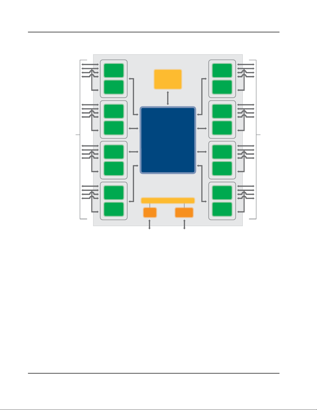
Figure 1: Block Diagram
80B803A_BK001_03
SP0
(4x or 1x)
SP1
(1x only)
SP4
(4x or 1x)
SP5
(1x only)
SP8
(4x or 1x)
SP9
(1x only)
SP12
(4x or 1x)
SP13
(1x only)
SP2
(4x or 1x)
SP3
(1x only)
SP6
(4x or 1x)
SP7
(1x only)
SP10
(4x or 1x)
SP11
(1x only)
SP14
(4x or 1x)
SP15
(1x only)
Enhanced Internal
Switching Fabric
Registers
Up to 4 Serial RapidIO Ports - 1x/4x Mode
or
Up to 8 Serial RapidIO Ports - 1x Mode
Up to 4 Serial RapidIO Ports - 1x/4x Mode
or
Up to 8 Serial RapidIO Ports - 1x Mode
Master and
Slave Devices
IEEE1149.6 Boundary Scan
Multicast
Engine
JTA GI
2
C
1. Functional Overview > Overview22
Embedded applications further benefit from the ability to route packets to over 64,000 endpoints
through hierarchical lookup tables, independent unicast and mul ticast routing mechanisms, and error
management extensions that provide proactive issue notification to the fabric controller. In addition,
the Tsi578 supports both in-band serial RapidIO access and out-of-band access to the full fabric
register set through the I2C interface.
Typical Applications
The Tsi578 can be used in many embedded communication applications. It provides chip-to-chip
interconnect between I/O devices and can replace existing proprietary backplane fabrics for
board-to-board interconnect which improves system cost and product time-to-market.
Tsi578 User Manual
June 6, 2016
Integrated Device Technology
www.idt.com
Page 23
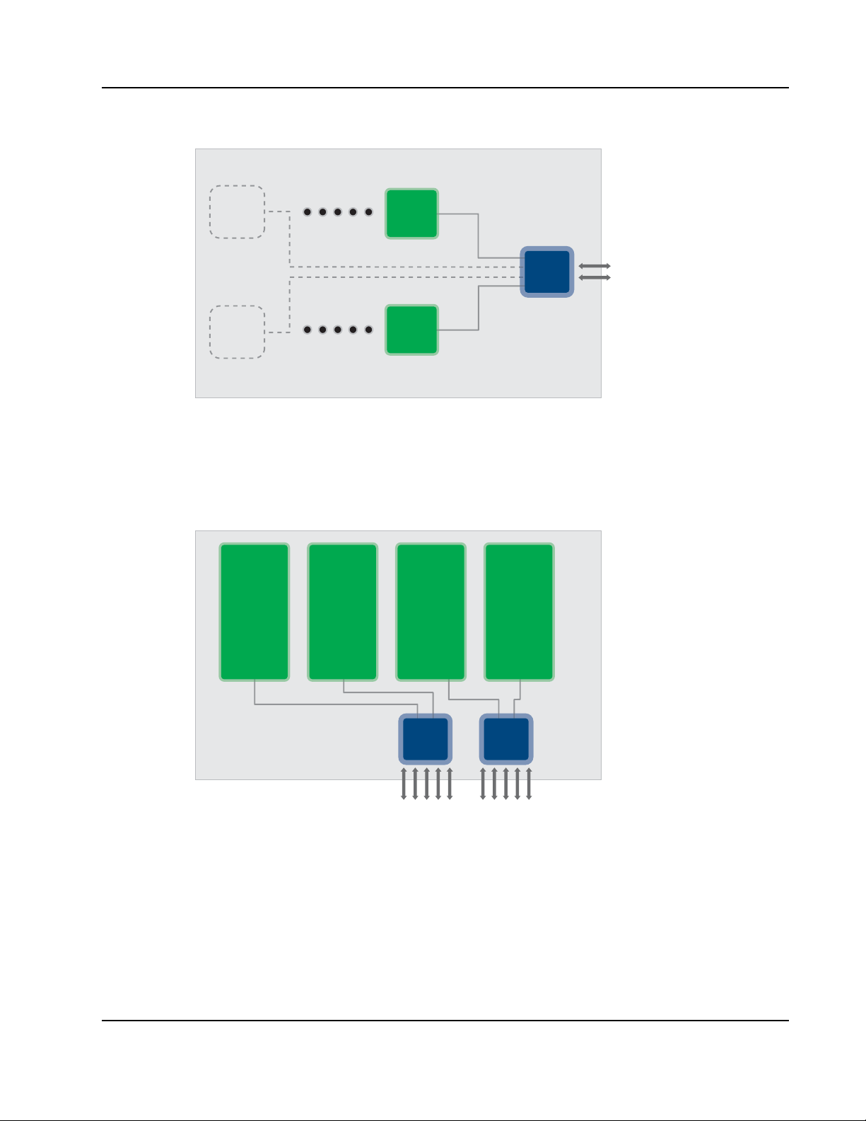
1. Functional Overview > Overview 23
80B803A_TA002_01
Serial RapidIO Mesh
AMC Slot AMC Slot AMC Slot AMC Slot
Tsi578 Tsi578
Figure 2: Processor Farm Mezzanine Diagram
DSP
Dual
Tsi578
DSP
80B803A_TA001_01
Serial
RapidIO
The Tsi578 provides traffic aggregation through packet prioritization when it is used with
RapidIO-enabled I/O devices. When it is in a system with multiple RapidIO-enabled processors it
provides high performance peer-to-peer communication through its non-blocking switch fabric.
Figure 3: Switch Carrier Blade
Integrated Device Technology
www.idt.com
Tsi578 User Manual
June 6, 2016
Page 24

1.1.1 Features
The Tsi578 contains the following features:
Electrical Layer Serial RapidIO Features
• Up to 8 ports in 4x Serial mode
• Up to 16 ports in 1x Serial mode (each 4x port can be configured independently as two 1x ports)
• Operating baud rate per data lane: 1.25 Gbit/s, 2.5 Gbit/s, or 3.125Gbit/s
• Full duplex bandwidth:
1. Functional Overview > Overview24
— 12.5 Gbit/s inbound and 12.5 Gbit/s outbound bandwidth at 3.125 GHz for a port configured
for 4x mode
1
— 3.125 Gbit/s inbound and 3.125 Gbit/s outbound bandwidth at 3.125 GHz for a port
configured for 1x mode
2
• Programmable serial transmit current with pre-emphasis equalization
• Loopback support for system testing
• Hot-insertion capable I/Os and hardware support
• Per-port power down modes to reduce power consumption
• Ability to reverse the bit ordering of a 4x port to simplify PCB layout
Transport Layer RapidIO Features
• Dedicated destination ID lookup table per port, used to direct packets through the switch
• Supports both hierarchical lookup tables and flat mode lookup tables (512 destinat ion IDs per
lookup table)
• Supports an optional, unique hierarchical destination ID lookup table covering all 64K possible
destinations ID
• Low-latency forwarding of the Multicast-Event control symbol
• Error management capability
• Performance monitoring capability
• Reset-system interrupt support
• Debug packet generation in debug mode
Multicast Engine Features
• One multicast engine provides dedicated multicast resources without impacting throughput on the
ports
• Eight multicast groups
• Sustained multicast output bandwidth, up to 10 Gbit/s per egress port
1. Usable data rate is 10 Gbit/s rather than 12.5 Gbit/s due to 8B/10B physical layer encoding.
2. Usable data rate is 2.5 Gbit/s rather than 3.125 Gbit/s due to 8B/10B physical layer encoding.
Tsi578 User Manual
June 6, 2016
Integrated Device Technology
www.idt.com
Page 25

1. Functional Overview > Overview 25
• 10 Gbit/s of instantaneous multicast input bandwidth
1
• Packets are replicated to each egress port in parallel
• The multicast engine can accep t a bursts of traffic with different packet sizes
• Arbitration at the egress port to allow management of resource contention between multicast or
non-multicast traffic.
System behavior when multicasting of packets which require responses is not defined in
the RapidIO Interconnect Specification (Revision 1.3) - Part 11 Multicast Specification.
Other Device Interfaces
• Master and Slave mode I2C port, supports up to 8 EEPROMs
• Optionally loads default configuration from ROMs during boot-up, through I
• Ability to read and write EEPROMs through I
2
C during system operation
2
C
• IEEE 1149.1 and 1149.6 boundary scan, with register access
Internal switching fabric (ISF)
• Full-duplex,80 Gbps line rate, non-blocking switching fab ric
• Prevents head-of-line blocking on each port
• Eight packet buffers per ingress port
• Eight packet buffers per egress port
Register Access
• Registers can be accessed from any RapidIO interface and both the JTAG interface and I2C
• Optionally loads default configuration from ROMs during boot-up, through I
2
C
• Supports one outstanding maintenance transaction per interface
• Supports 32-bit wide (4 byte) register access
1. All bandwidths assume the internal switching fabric is clocked at 156.25 MHz.
Integrated Device Technology
www.idt.com
Tsi578 User Manual
June 6, 2016
Page 26

1.2 Serial RapidIO Interface
The Tsi578 provides high-performance serial RapidIO interfaces that are used to provide connectivity
for control plane and data plane applications. All RapidIO interfaces are compliant with the RapidIO
Interconnect Specification (Revision 1.3).
This section describes the transport layer features common to all Tsi578 RapidIO interfaces. The
RapidIO interface has the following capabilities:
• RapidIO packet and control symbol transmission
• RapidIO packet and control symbol reception
• Register access through RapidIO maintenance requests
1.2.1 Features
The following features are supported:
• Up to eight 4x-mode or up to 16 1x-mode serial RapidIO ports operating at up to 3.125 Gbits/s
• Per-port destination ID look-up table, used to direct packets through the switch
This is a IDT-specific implement ation. The RapidIO Inter connect Spec ification (Revision 1.3)
standard implementation of look-up tables is also supported.
1. Functional Overview > Serial RapidIO Interface26
• RapidIO error management extensions, including both hardware and software error recovery
(described in RapidIO Interconnect Specification (Revision 1.3) Part 8)
• Low latency forwarding of the multicast control symbol
• Proprietary registers for performance monitoring and tuning
• Both cut-through and store-and-forward modes for performance tuning
• Debug packet generation and capture
• Multicast functionality (described in RapidIO Interconnect Specification (Revision 1.3) Part 11)
• Head-of-line blocking avoidance
1.2.2 Transaction Flow Overview
Packets and control symbols are received by the Serial RapidIO Electrical Interface (Serial MAC) and
forwarded to the RapidIO Interface (for more information on the Serial MAC, refer to “Serial RapidIO
Electrical Interface” on page 65). Received packets have their integrity verified by error checking.
Once the packet’s integrity has been verified, the destination ID of the packet is used to access the
routing lookup table to determine which port the packet should be forwarded to and whether the packet
is a multicast packet. The packet is then buffe red by the Internal Switch Fabric (ISF) for transmission
to the port. After the packet is transferred to the egress port, the port transmits the packet. If a packet
fails the CRC check, the packet is discarded and the transmitter is instructed to retransmit the packet
through the use of control symbols.
The egress port receives packets to be transmitted from the ISF. The integrity of packets forwarded
through the ISF is retained by sending the CRC code received with the packet. For more information
on the input and ouput queues, refer to “Packet Queuing” on page 95.
Tsi578 User Manual
June 6, 2016
Integrated Device Technology
www.idt.com
Page 27

1. Functional Overview > Multicast Engine 27
The packet transmitter and the packet receiver cooperate to ensure that packets are never dropped
(lost). A transmitter must retain a packet in its buffers until the port receives a packet accepted control
symbol from the other end of the link.
1.2.3 M aintenance Requests
A maintenance packet is the only packet type that will be modified by the switch. If the hop count
value of the maintenance request is 0, the maintenance request is forwarded to the register bus for
processing. The register bus accesses the registers in the appropriate port. The response to the
maintenance request is compiled into a maintenance response packet and queued by the port for
transmission. Maintenance packets with a non-zero hop count value have their hop count decremented,
CRC recomputed, and are then forwarded to the port selected by the destination ID value in the look up
table.
1.2.4 Control Symbols
Control symbols received by the Tsi578 have their CRC validated, and their field values checked. If
either the CRC is incorrect or the control symbol field values are incorrect, a packet-not-accepted
control symbol is sent back and the control symbol is discarded. Otherwise, the control symbol is used
by the port for purposes of packet management in the transmit port or link maintenance.
1.3 Multicast Engine
The Tsi578 multicast functionality is compliant to the RapidIO Version 1.3 Part 11 Multicast
Specification.
1.3.1 Multicast Operation
In a multicast operation, packets are received at the speed of any ingress port (up to 10 Gbits/s) and
broadcast at the speed of the egress ports (up to 10 Gbits/s for a 4x mode port operating at
3.125 Gbits/s) to multiple ports capable of accepting packets for transmission. The maximum amount
of data that can be transmitted by the switch is 70 Gbits/s for seven egress ports operating at maximum
width of 4x and a lane speed of of 3.125 Gbit/s, based on the the number of ports on the Tsi578.
Packets are routed to the multicast engine based on their destinationID and Transaction Type (TT) field
value. If no match is found for the destinat ionID and TT field, then the ingress lookup tables are used to
route the packet. A maximum of eight different DestID/TT field combinations can be routed to the
multicast engine. Each destinationID/TT set can be mult icast to a different set of egress ports. A set of
egress ports that packets are multicast to is called a multi cast group and is re prese nted by the multicas t
mask in the group table. A multicast packet is never sent out on the port that it was received on. Any
number of ports can share the same multicast group.
Multicast packets are accepted by egress ports based on priority. In the event that multicast and unicast
traffic are competing for resources in the egress port, multicast specific egress arbitration can be used
to favour multicast or unicast traffic. This allows a group of endpoints that need to multicast to each
other to share the same multicast mask.
Integrated Device Technology
www.idt.com
Tsi578 User Manual
June 6, 2016
Page 28

1.3.2 Features
The Tsi578 supports multicast packet replication in accordance with RapidIO Specification Version
1.3, Part 11 Multicast.
The Tsi578 includes the following features:
• One multicast engine provides dedicated multicast resources without impacting throughput on the
ports
• Eight multicast groups
• Sustained multicast output bandwidth, up to 10 Gbit/s per egress port
• 10 Gbit/s of instantaneous multicast input bandwidth
• Packets are replicated to each egress port in parallel
• The multicast engi ne can accept bursts of traffic with different packet sizes
• Arbitration at the egress port to allow management of resource contention between multicast or
unicast traffic
System behavior for the multica st ing of pa ck ets wh ich re quir e res pon ses is not defi ned i n th e
RapidIO Interconnect Specification (Revision 1.3) - Part 11 Multicast Specification.
1. Functional Overview > Serial RapidIO Electrical Interface28
1
1.4 Serial RapidIO Electrical Interface
The T si578 has eight Media Access Controllers (MAC) comprising the 16 Serial RapidIO ports. The 16
ports are grouped into pairs consisting of one even numbered port and one odd numbered port. Each
port has flexible testing features including multiple loopback modes and bit error rate testing. Each pair
of ports share four differential transmit lanes and four differential receive lanes.
Even and odd number ports have different capabilities. Even numbered ports can operate in either 4x or
1x mode, while odd numbered ports can only operate in 1x mode. When the even numbered port is
operating in 4x mode, it has control over all four differential pairs (designated Lanes A, B, C and D). In
4x mode, the default state of the odd numbered port is powered on. All registers in the even and odd
numbered port are accessible but the odd numbered port does not have access to the PHY. In order to
decrease the power dissipation of the port, the odd numbered port can be powered down in this
configuration. When the even numbered port is operating in 1x mode it uses only Lane A and the odd
numbered port is permitted to operate in 1x mode using Lane B.
The Tsi578 MAC and SerDes interconnect block diagram is shown in the following figure.
1. All bandwidths assume the internal switching fabric is clocked at 156.25 MHz.
Tsi578 User Manual
June 6, 2016
Integrated Device Technology
www.idt.com
Page 29
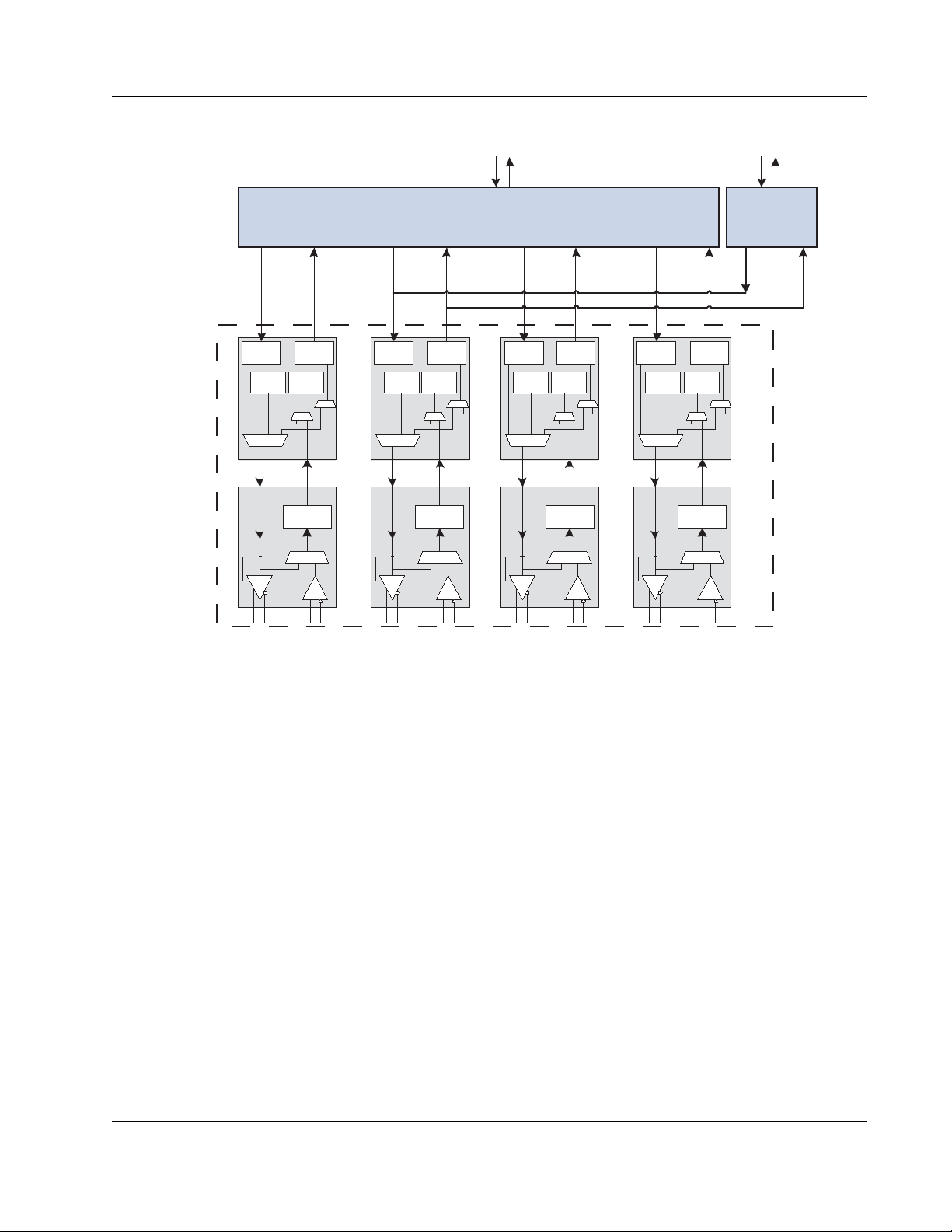
1. Functional Overview > Serial RapidIO Electrical Interface 29
Figure 4: Tsi578 MAC Block Diagram
8B/10B
Enc
PRBS
Gen
SERDES
Lane A
8B/10B
PRBS
Chk
CDR
Dec
Serial Rapid IO Registers and Buffers
Even-numbered Ports (4x mode or 1x mode)
8B/10B
8B/10B
Enc
PRBS
Gen
PRBS
Chk
CDR
Dec
SERDES
Lane B
8B/10B
Enc
PRBS
PRBS
Gen
Chk
CDR
SERDES
Lane C
8B/10B
Dec
8B/10B
Enc
PRBS
PRBS
Gen
SERDES
Lane D
8B/10B
Dec
Chk
CDR
Odd
Numbered
Ports
(1x mode only)
Each serial RapidIO MAC includes the following features:
• One port in 4x Serial mode
• Two ports in 1x Serial mode (each 4x port can be configured as two 1x ports)
• RapidIO standard operating baud rate per data lane: 1.25 Gbit/s, 2.5 Gbit/s, or 3.125 Gbit/s
— 12.5 Gbit/s inbound and 12.5 Gbit/s outbound bandwidth at 3.125 Gbps for a port configured
for 4x mode
— 3.125 Gbit/s inbound and 3.125 Gbit/s outbound bandwidth at 3.125 Gbps for a port
configured for 1x mode
• Adjustable receive equalization that is programmable per lane
• Serial loopback with a built-in testability
• Bit error rate testing (BERT)
• Scope function of eye signals
• Hot-insertion capable I/Os and hardware support
Integrated Device Technology
www.idt.com
Tsi578 User Manual
June 6, 2016
Page 30

1. Functional Overview > Internal Switching Fabric (ISF)30
1.5 Internal Switching Fabric (ISF)
The Internal Switching Fabric (ISF) is the crossbar switching matrix at the core of the Tsi578. It
transfers packets from ingress ports to egress ports and prioritizes traffic based on the RapidIO priority
associated with a packet and port congestion.
The ISF has the following features:
• Full-duplex, non-blocking, crossbar-based switch fabric
• 10 Gbits/s fabric ports allow up to 10x internal speed up
• Manages head-of-line blocking on each port
• Cut-through and store-and-forward switching of variable-length packets
1.6 Internal Register Bus (AHB)
An internal multi-master Advanced High Performance Bus (AHB) allows any RapidIO port to
configure and maintain the entire device. When the Tsi578 receives a RapidIO maintenance packet
destined for itself, it translates the packet into register read or write request on the AHB.
The device registers can also be accessed through the JTAG interface or the I
2
C interface.
1.7 I2C Interface
The I2C Interface provides a master and slave serial interface that can be used for the following
purposes:
• Initializing device registers from an EEPROM after reset
• Reading and writing external devices on the I
• Reading and writing Tsi578’s internal registers for management purposes by an external I
master
2
The I
C Interface has the following features:
• Operates as a master or slave on the I
— Multi-master support
– Arbitrates among multiple masters for ownership of the I
– Automatically retries accesses if arbitration is lost
– Provides timeout indication if the Tsi578 is unable to arbitrate for the I
2
C bus
2
C bus
2
C bus
2
C bus
2
C
Tsi578 User Manual
June 6, 2016
Integrated Device Technology
www.idt.com
Page 31

1. Functional Overview > I2C Interface 31
—I2C Interface: Master interface
– Sup ports 7-bit device addressing
– Sup ports 0, 1, or 2-byte periph eral addressing
– Supports 0, 1, 2, 3, or 4-byte data transfers
– Reverts to slave mode if arbitration is lost
– Supports clock stretching by an external slave to limit bus speed to less than 100 kHz
– Handles timeouts and reports them through interrupts
2
—I
C Interface: Slave interface
– Slav e address can be lo ad ed from three sources: power-up signals, boot load from
EEPROM, or by software configuration
– Provides read and write accesses that are 32 bits in size to all Tsi578 registers
– Ignores General-Call accesses
– Ignores Start-Byte protocol
– Prov ides a status register for determination of Tsi578’s health
– Slave operation enabled/disabled through power-up signal, boot load from EEPROM, or
by software configuration
– Provides mailbox registers for communicating between maintenance software operating
2
C masters
• Supports I
on RapidIO based processors and external I
2
C operations up to 100 kHz
• Provides boot-time register initialization
— Supports 1- and 2-byte addressing of the EEPROM selected by power-up signal
— Verifies the number of registers to be loaded is legal before loading registers
— Supports up to 2K byte address space and up to 255 address/data pairs for register
configuration in 1-byte addressing mode, or up to 65 Kbyte address space and up to 8 K-1
address/data pairs in 2-byte add r essing mode.
— Supports chaining to a different EEPROM and/or EEPROM address during initialization.
2
The I
C Interface does not support the following features:
• START Byte protocol
— Tsi578 does not provide a START Byte in transactions it masters
— Tsi578 does not respond to START Bytes in transactions initiated by other devices. The
Tsi578 will respond to the repeated start following the start byte provided the 7-bit address
provided matches the Tsi578 device address.
Integrated Device Technology
www.idt.com
Tsi578 User Manual
June 6, 2016
Page 32

1. Functional Overview > JTAG Interface32
• CBUS compatibility
— T si578 does not provide the DLEN signal
— Tsi578 does not respond as a CBUS device when addressed with the CBUS address. The
Tsi578 will interpret the CBUS address like any other 7-bit address and compare it to its
device address without consideration for any other meaning.
• Fast Mode or High-Speed Mode (HS-MODE)
• Reserved 7-bit addresses should not be used as the Tsi578’s 7-bit address. If a reserved address is
programmed, the T si578 will respond to that address as though it were any other 7-bit address with
no consideration of any other meaning.
• 10-bit addressing
— Tsi578 must not have its device address programmed to the 10-bit address selection
(11110XXb) in syst em s that use 10-bit add ressing. The Tsi578 will interpret this address like
any other 7-bit address and compare it to its device address without consideration for any
other meaning.
• General Call. The general call address will be NACK’d and the remainder of the transaction
ignored up to a subsequent Restart or Stop.
1.8 JTAG Interface
The JT AG interface in Tsi578 is fully compliant with IEEE 1149.6 Boundary Scan Testing of Advanced
Digital Networks as well as IEEE 1149.1 Standard Test Access Port and Boundary Scan Architecture
standards. There are five standard pins asso ciated with the interface (TMS, TCK, TDI, TDO and
TRST_b) which allow full control of the internal TAP (Test Access Port) controller.
The JTAG Interface has the following features:
• Contains a 5-pin Test Access Port (TAP) controller, with support for the following registers:
— Instruction register (IR)
— Boundary scan register
—Bypass register
— Device ID register
— User test data register (DR)
• IDT-specific pin (BCE) which allows full 1149.6 compliant boundary-scan tests. This pin should
be held high on the board.
• Supports debug access of Tsi578’s configuration registers
• Supports the following instruction opcodes:
— Sample/Preload
Tsi578 User Manual
June 6, 2016
—Extest
— EXTEST_PULSE (1149.6)
— EXTEST_TRAIN (1149.6)
Integrated Device Technology
www.idt.com
Page 33

1. Functional Overview > JTAG Interface 33
— Bypass
—Hi-Z
— IDCODE
—Clamp
— User data select
Integrated Device Technology
www.idt.com
Tsi578 User Manual
June 6, 2016
Page 34

1. Functional Overview > JTAG Interface34
Tsi578 User Manual
June 6, 2016
Integrated Device Technology
www.idt.com
Page 35

2. Serial RapidIO Interface
This chapter describes the serial RapidIO interface of the Tsi578. It includes the following information:
• “Overview” on page 35
• “Transaction Flow” on page 37
• “Lookup Tables” on page 37
• “Maintenance Packets” on page 53
• “Multicast Event Control Symbols” on page 55
• “Reset Control Symbol Processing” on page 57
• “Data Inte grity Checking” on page 57
• “Error Management” on page 57
• “Hot Insertion and Hot Extraction” on page 59
• “Loss of Lane Synchronization” on page 62
35
2.1 Overview
The Tsi578 provides high-performance serial RapidIO interfaces that are used to provide connectivity
for control plane and data plane applications. All RapidIO interfaces are compliant with the RapidIO
Interconnect Specification (Revision 1.3).
This section describes the transport layer features common to all Tsi578 RapidIO interfaces. The
RapidIO interface has the following capabilities:
• RapidIO packet and control symbol transmission
• RapidIO packet and control symbol reception
• Register access through RapidIO maintenance requests
2.1.1 Features
The following features are supported:
• Up to eight 4x-mode or up to 16 1x-mode serial RapidIO ports operating at up to 3.125 Gbits/s
• Per-port destination ID look-up table, used to direct packets through the switch
This is a IDT -s pecific implementation. The RapidIO Inter connect Specification (Revis ion 1.3)
standard implementation of look-up tables is also supported.
• RapidIO error management extensions, including both hardware and software error recovery
(described in RapidIO Interconnect Specification (Revision 1.3) Part 8)
• Low latency forwarding of the multicast control symbol
Integrated Device Technology
www.idt.com
Tsi578 User Manual
June 6, 2016
Page 36

• Proprietary registers for performance monitoring and tuning
• Both cut-through and store-and-forward modes for performance tuning
• Debug packet generation and capture
• Multicast functionality (described in RapidIO Interconnect Specification (Revision 1.3) Part 11)
• Head-of-line blocking avoidance
2.1.2 Transaction Flow Overview
Packets and control symbols are received by the Serial RapidIO Electrical Interface (Serial MAC) and
forwarded to the RapidIO Interface (for more information on the Serial MAC, refer to “Serial RapidIO
Electrical Interface” on page 65). Received packets have their integrity verified by error checking.
Once the packet’s integrity has been verified, the destination ID of the packet is used to access the
routing lookup table to determine which port the packet should be forwarded to and whether the packet
is a multicast packet. The packet is then buffe red by the Internal Switch Fabric (ISF) for transmission
to the port. After the packet is transferred to the egress port, the port transmits the packet. If a packet
fails the CRC check, the packet is discarded and the transmitter is instructed to retransmit the packet
through the use of control symbols.
The egress port receives packets to be transmitted from the ISF. The integrity of packets forwarded
through the ISF is retained by sending the CRC code received with the packet. For more information
on the input and ouput queues, refer to “Packet Queuing” on page 95.
2. Serial RapidIO Interface > Overview36
The packet transmitter and the packet receiver cooperate to ensure that packets are never dropped
(lost). A transmitter must retain a packet in its buffers until the port receives a packet accepted control
symbol from the other end of the link.
2.1.3 M aintenance Requests
A maintenance packet is the only packet type that will be modified by the switch. If the hop count
value of the maintenance request is 0, the maintenance request is forwarded to the register bus for
processing. The register bus accesses the registers in the appropriate port. The response to the
maintenance request is compiled into a maintenance response packet and queued by the port for
transmission. Maintenance packets with a non-zero hop count value have their hop count decremented,
CRC recomputed, and are then forwarded to the port selected by the destination ID value in the look up
table.
2.1.4 Control Symbols
Control symbols received by the Tsi578 have their CRC validated, and their field values checked. If
either the CRC is incorrect or the control symbol field values are incorrect, a packet-not-accepted
control symbol is sent back and the control symbol is discarded. Otherwise, the control symbol is used
by the port for purposes of packet management in the transmit port or link maintenance.
Tsi578 User Manual
June 6, 2016
Integrated Device Technology
www.idt.com
Page 37

2. Serial RapidIO Interface > Transaction Flow 37
Tip
Tip
2.2 Transaction Flow
The Tsi578 receives a RapidIO packet on one of its RapidIO ports. After performing integrity checks,
such as validating a CRC, the interface logic locates the destination ID in the packet. The Tsi578 uses
this information to determine to which egress port the packet must be sent and whether it is a multicast
packet. It consults a user-configurable lookup table, which maps destination ID into egress port
numbers.
The RapidIO port transfers the packet to the Switch ISF where it is buf fered and transferred to an
egress port or to the Multicast Engine. The Switch ISF is non-blocking, which means that all ports can
switch data at the same time as long as they are not switching data from multiple ports to a single port.
The Switch ISF manages head-of-line blocking, which means that when a packet cannot be moved to
an egress port (for example, because multiple ingress ports are trying to send to the same egress port),
the Switch ISF selects another packet to service from the same ingress port.
The ingress queue of T s i578 can operate in two modes: store-and-forward and cut-through modes (see
“RapidIO Port x Control Independent Register” on page 319). In store-and-forward mode, the ingress
port of the device waits for the arrival of the whole packet before sending it to the ISF. In cut-through
mode, the ingress port transmits the packet as soon as the ISF grants access (when the routing
information is received). However, in both modes the egress port always operates in cut-through mode:
the packet is immediately forwarded. A copy of the packet is saved at the egress port so that it can be
retransmitted should an error occur.
RapidIO provides a stomp function to abort partially transmitted packets that are later
determined to have data integrity errors or similar errors. This means if the Tsi578 finds that a
packet that is being cut-through has an error, it may send a stomp control symbol to notify the
receiver that the packet was in error and all received data of the erred packet should be
dropped.
Packets delivered to a Multicast Engine (MCE) are replicated, based on user-configured multicast
groups. The MCE sends copies of the original packet to the egress ports in a parallel fashion.
Packets can cut-through from the ingress port to the Multicast Work Queue and from the
Multicast W ork Queue to the Broadc ast Buffers. A complete packe t copy must be received by
a Broadcast Buffer before it attempts to forward the packet copy to the egress port.
2.3 Lookup Tables
Lookup tables (LUTs) are used to direct incoming packets to output ports. An ingress port performs
this routing operation by mapping the destination ID field of an incoming packet to an egress port
number on the RapidIO switch. The ingress port does this by using the destination ID as an index to a
lookup table containing user-defined egress port numbers.
Each RapidIO port has its own uniquely configurable lookup table. Configuration and mainten an ce of
the LUTs is compliant with the RapidIO Interconnect Specification (Revision 1.3). All LUTs are
written simultaneously by these registers. Additionally, the LUT of each port can be accessed using
device-specific registers.
Integrated Device Technology
www.idt.com
Tsi578 User Manual
June 6, 2016
Page 38

The LUTs support two modes of operation, selectable on a per-port basis: “Flat Mode” on page 40 and
“Hierarchical Mode” on page 45. Flat mode is the default mode and it supports destination IDs in the
range of 0 to 511, with a default port for destination IDs outside this range. The hierarchical model
covers the full large system range of 64-KB destination IDs, with some limitations.
To ensure high system reliability, the lookup tables are parity protected. System software must
intervene when a parity error is detected. The Tsi578 guarantees that packets are not incorrectly
delivered when the lookup table incurs single bit errors.
When a packet arrives at the ingress port, the destination ID of the packet is examined against
the Multicast Group Table to determine if the packet is a multicast packet (see “Multicast” on
page 103).
2.3.1 Filling the Lookup Tables
The process of filling in the LUT is composed of the following series of register writes:
• The “RapidIO Route Configuration DestID CSR” on page 260 is lo aded wit h the destination ID
value to be routed
• The “RapidIO Route Configuration Output Port CSR” on page 261 is written with the desired
egress port number
2. Serial RapidIO Interface > Lookup Tables38
If there is an attempt to write a destination ID with a value of greater than 511 into the “RapidIO Route
Configuration DestID CSR” on page 260 using the LRG_CFG_DESTID and CFG_DESTID fields, the
upper seven bits of the destination ID in the LRG_CFG_DESTID field is truncated.
“RapidIO Route LUT Size CAR” on page 256 only advertises the switch can map 512
destination IDs. This is due to the fact this register is global in scope, whereas the ports can be
independently configured for either flat mod e or hierarchical mode lookup tables.
The LUT of all the ports can be loaded simultaneously if it is desired to have the same routing entries in
all of the ports required. The loading process is similar to loading an individual port's LUT, however
alternative registers are used. The register addresses are:
• “RapidIO Route Configuration DestID CSR” on page 260 at 0x0070 or
• “RapidIO Port x Route Config DestID CSR” on page 314 at 0x10070
• “RapidIO Route Configuration Output Port CSR” on page 261 at 0x0074 or
• “RapidIO Port x Route Config Output Port CSR” on page 315 at 0x10074
The register sets are identical except that SPx_ROUTE_CFG_PORT are per-port configuration
registers and include an auto-increment bit to increment the contents of SPx_ROUTE_CFG_DESTID
after a read or write operation.
Tsi578 User Manual
June 6, 2016
Integrated Device Technology
www.idt.com
Page 39

2. Serial RapidIO Interface > Lookup Tables 39
Yes
Start
LUT_512 = 1 in the
SPx_MODE register
No
Heirarchical
Width of DestID
8 bit (TT=0)
16 bit (TT=1)
MSB of DestID[15:8] ==
BASE field in
SPx_ROUTE_BASE
Yes
No
Obtain egress port
from GLOBAL LUT
using DestID[15:8]
Obtain egress port
from LOCAL LUT
using DestID[7:0]
LUT entry mapped
and
egress port < Port_Total
Yes
No
Route to egress port
defined in LUT
DestID < 256
Yes
Obtain egress port
from LOCAL LUT
using DestID[7:0]
No
DestID < 512
No
Flat
Yes
Obtain egress port
from GLOBAL LUT
using DestID[8:0]
Default egress
port mapped?
Yes
No
Discard packet
Route to default
egress port
Figure 5: LUT Mode of Operation
Integrated Device Technology
www.idt.com
Tsi578 User Manual
June 6, 2016
Page 40

2.3.2 LUT Modes
The LUT mode, flat or hierarchical, is selected on a per-port basis through the LUT_512 field value in
the “RapidIO Port x Mode CSR” on page 310.
2.3.3 Flat Mode
A flat mode LUT is a table that maps destination IDs 0 to 511 to user selectable egress ports.
Destination IDs that fall outside this range are sent to the egress port identified in the RIO Route LUT
Attributes CSR (see “RapidIO Route LUT Attributes (Default Port) CSR”).
Flat mode is the default mode of operation of the LUT.
Figure 6 shows the configuration of the Local and Global Lookup tables (LUT) in Flat mode.
2. Serial RapidIO Interface > Lookup Tables40
Tsi578 User Manual
June 6, 2016
Integrated Device Technology
www.idt.com
Page 41

2. Serial RapidIO Interface > Lookup Tables 41
100
1FF
00
FF
DestID Port
DestID Port
Local LUT
Global LUT
DestID MSB is loaded into
Global LUT through the
LRG_CFG_DEST_ID and
CFG_DEST_ID fields in the
RIO_ROUTE_CFG_DESTID register
Egress Port is loaded into
the Global LUT through the
PORT field in the
RIO_ROUTE_CFG_PORT register
DestID LSB is loaded into the
Local LUT through the
CFG_DEST_ID field in the
RIO_ROUTE_CFG_DESTID register
Egress Port is loaded into
the Local LUT through the
PORT field in the
RIO_ROUTE_CFG_PORT register
Figure 6: Flat Mode Routing
An incoming packet's destination ID is examined following the process in the flowchart in Figure 5.
The egress port number is obtained from the LUT if there is a match between the destination ID in the
packet header and the table. If there is no match, the packet is routed based on the default egress port
programmed into “RapidIO Route LUT Attributes (Default Port) CSR” on page 262. If the default port
is unmapped, the packet is discarded and the Tsi578 raises the IMP_SPEC_ERR bit in the “RapidIO
Port x Error Detect CSR” on page294.
Integrated Device Technology
www.idt.com
Tsi578 User Manual
June 6, 2016
Page 42

Figure 7 shows an example of flat mode operation.
100
1FF
00
FF
DestID Port
DestID Port
Local LUT
Global LUT
DestID MSB is loaded into Global LUT through
the LRG_CFG_DESTID field in the
RIO_ROUTE_CFG_DESTID register
Egress Port is loaded
into Global LUT through the
PORT field in the
RIO_ROUTE_CFG_PORT
register
Tsi57x
Tsi57x
Tsi57x
DSP
DSP
DSP
DSP
DestID = 0x13
DestID = 0x11
DestID = 0x12
DestID = 0x10
DestIDs accessible through
this link = 0x02xx to 0xFFxx
DestIDs accessible
through this link = 0x01xx
DestID =
0xFE33
Ingress Packets
ABC
8
14 9
0
1
2
3
DestID =
0x0137
DestID =
0x12
Example packets
{
{
Default Port
14
137 9
10
11
12
13
3
2
1
0
DestID MSB is loaded into Global LUT through
the CFG_DESTID field in the
RIO_ROUTE_CFG_DESTID register
{
Egress Port is loaded into Global LUT
through the PORT field in the
RIO_ROUTE_CFG_PORT register
{
Figure 7: Flat Mode Routing Example
2. Serial RapidIO Interface > Lookup Tables42
Tsi578 User Manual
June 6, 2016
Integrated Device Technology
www.idt.com
Page 43

2. Serial RapidIO Interface > Lookup Tables 43
00_00
02_00
FF_FF
02
03
01
04
etc.
512-LUT
Destination ID
Out of Range
00
DEFAULT_OUT_PORT in the
00_01
00_02
00_03
01_FF
00_04
RIO_LUT_ATTR register
2.3.3.1 Flat LUT Programming
Each of the ports on the Tsi578 has its own lookup table. Each lookup table can be programmed with
different values which allows each port to route packets differently. The lookup table maps the packet
to the correct output port based on the destination ID. The capability of each port having their own
LUT is functionality that is not required in the RapidIO Interconnect Specification (Revision 1.3).
LUT entries can be reprogrammed at any time during normal system operation. However, software
must ensure transactions have completed before reprogramming the LUTs.
Figure 8 shows an example of a LUT in flat mode. In this example, a destination ID of 0x0002, or
0x02, is routed by the switch to output port 1. A destination ID of 0x0003, or 0x03, is routed out port 0
and destination IDs greater than 0x1FF are routed out port 4.
Figure 8: Flat Mode LUT Configuration Example
Registers Used in Lookup Table Configuration
The Tsi578’s RapidIO interfaces are compliant with the RapidIO Interconnect Specification
(Revision 1.3). The following standard RapidIO registers are used by the Tsi578 for programming the
lookup tables:
• “RapidIO Route Configuration DestID CSR” on page 260
• “RapidIO Route Configuration Output Port CSR” on page 261
• “RapidIO Route LUT Size CAR” on page 256
• “RapidIO Route LUT Attributes (Default Port) CSR” on page 262
• “RapidIO Port x Local Routing LUT Base CSR” on page 316
Other related registers are IDT specific and include the following:
• “RapidIO Port x Route Config DestID CSR” on page 314
Integrated Device Technology
www.idt.com
Tsi578 User Manual
June 6, 2016
Page 44

2. Serial RapidIO Interface > Lookup Tables44
• “RapidIO Port x Route Config Output Port CSR” on page 315
• “RapidIO Port x Local Routing LUT Base CSR” on page 316
Other indirectly related (multicast) registers include:
• “RapidIO Multicast Mask Configuration Register” on page 263
• “RapidIO Multicast DestID Configuration Register” on pag e 265
All lookup table entries are in an unknown state after power-up. All entries should be
programmed to a mapped or unmapped state to ensure predictable operation. IDT strongly
recommends that the value 0xFF be used as the port value for writing unmapped lookup table
entries. An unmapped lookup table entry returns the value of 0xFF as the port value when
read.
Lookup Table Configuration Examples
The Tsi578 lookup tables can be configured through an external EEPROM or through software
maintenance writes to the Tsi578 registers.
IDT strongly recommends that the entire lookup table be configured on each port to avoid
undefined lookup table entries which can cause non-deterministic behavior.
The following sequence programs the lookup tables using the broadcast (BC) offset:
1. Write the destination ID to be configured or queried using the broadcast (BC) offset (0x10070) in
the “RapidIO Port x Route Config DestID CSR” on page 314.
2. Read the “RapidIO Port x Route Config Output Port CSR” on page 315 register to determine the
current egress port for the destination ID, or write this register to change the configuration of the
destination ID.
Example One: Adding a Lookup Table Entry
In the following example, routing is added for all ports to route destination ID 0x98 to output port
0x4.To add a lookup table, perform the following steps:
1. Write to the “RapidIO Port x Route Config DestID CSR” on page 314, using the broadcast offset
(0x10070), with a value of 0x00000098. This makes the destination ID 0x98.
2. Write to the “RapidIO Port x Route Config Output Port CSR” on page 315, using the broadcast
(BC) offset (0x10074), a value of 0x00000004. This makes the egress Port 0x4 for destination ID
0x98.
Tsi578 User Manual
June 6, 2016
Integrated Device Technology
www.idt.com
Page 45

2. Serial RapidIO Interface > Lookup Tables 45
Example Two: Adding a Lookup Table Entry
In the following example, routing is added for port 0x5 to route destination ID 0x20 to output port 0x3.
To add a lookup table, complete the following steps:
1. Write to the “RapidIO Port x Route Config DestID CSR” on page 314, using the offset for port 5
(0x11570), with a value of 0x80000020. This makes the destination ID 0x20 and the
Auto-increment 0x1
2. Write to the “RapidIO Port x Route Config Output Port CSR” on page 315, using the offset for port
5 (0x11574), with a value of 0x00000003. This programs Port 0x3.
In this example, if a further write to “RapidIO Port x Route Config DestID CSR” on page 314
(offset 0x11574) was performed the output port for destination ID 0x21 is configured
Example Three: Verifying / Reading a Lookup Table Entry
In the following example, output port for destination ID 0x54 is read. To verify and read a lookup table
entry, perform the following steps:
1. Write to the “RapidIO Port x Route Config DestID CSR” on page 314, using the broadcast (BC)
offset (0x10070), with a value of 0x00000054. This programs the destination ID 0x54.
2. Read to the value in “RapidIO Port x Route Config Output Port CSR” on page 315, using the
broadcast (BC) offset (0x10074). This value represents the output port for packets with destination
ID 0x54
The value reported back is assumed to be for all ports but it only reports back the value in port
0.
2.3.4 Hierarchical Mode
The hierarchical mode of operation of the LUT allows the full range of 65536 16-bit destination IDs to
be mapped. This mode is enabled by setting RIO_SP_MODE.LUT_512 = 0. The hierarchical mode of
operation uses two LUTs, each containing 256 entries.
• For packets with 8-bit destination IDs, the i ngress port us es the ID as an inde x into the “loc al” LUT
(see “Flat Mode”).
• For packets with 16-bit destin ation IDs:
— If the most significant 8 bits of the packet’s destination ID match the value configured in
SPx_ROUTE_BASE.BASE register field, the ingress port uses the least significant 8 bits of
the packet’s destination ID to index the “local LUT” and retrieve an egress port number.
— If the most significant 8 bits of the packet’s destination ID do not match the value configured
in the SPx_ROUTE_BASE.BASE register field, the ingress port uses the most significant 8
bits of the packet’s destination ID to index the “global LUT” and retrieve an egress port
number. Thus, the majority of the 16-bit destination ID number space is covered by the global
LUT, with groups of 256 destination IDs targeting the same egress switch port.
Integrated Device Technology
www.idt.com
Tsi578 User Manual
June 6, 2016
Page 46

2. Serial RapidIO Interface > Lookup Tables46
00
FF
00
FF
MSB of
DestID
Port
LSB
of DestID
Port
xx
{
}
DestID LSB is loaded into the Local LUT through the
CFG_DEST_ID field of the RIO_ROUTE_CFG_DESTID register
Egress Port is loaded into the Local LUT through the
PORT field of the RIO_ROUTE_CFG_PORT register
DestID MSB is loaded into the
Global LUT through the BASE field
in the SPx_ROUTE_BASE register
DestID MSB is loaded into
the Global LUT through the
LRG_CFG_DEST_ID field in the
RIO_ROUTE_CFG_DESTID register
Global LUT
Local LUT
Default Port
Egress Port is loaded into the
Global LUT through the PORT field
of the RIO_ROUTE_CFG_PORT
register
If the result of a lookup yields an egress port number greater than the value in PORT_T OTAL
(“RapidIO Switch Port Information CAR” on page 252), the incoming packet is routed to the Default
Port defined by “RapidIO Route LUT Attributes (Default Port) CSR”. If the default port is unmapped,
the packet is discarded and the Tsi578 raises the IMP_SPEC_ERR bit in the “RapidIO Port x Error
Detect CSR” on page 294.
Register RIO_LUT_SIZE only advertises the switch can map 512 destination IDs. This is due
to the fact that RIO_LUT_SIZE is a register with global scope, but the ports can be
independently configured for either flat mode or hierarchical mode lookup.
Figure 9: Hierarchical Mode
Figure 10 shows an example of hierarchical mode operation.
Tsi578 User Manual
June 6, 2016
Integrated Device Technology
www.idt.com
Page 47

2. Serial RapidIO Interface > Lookup Tables 47
Tsi57x
Tsi57x Tsi57x
DSP
DSP
DSP
DSP
DestID =
0x2813
DestID =
0x2811
DestID =
0x2812
DestID =
0x2810
DestIDs accessible through
this link = 0xFExx, 0xFFxx
DestIDs accessible through
this link = 0x02xx,
0x01xx, 0x00xx
DestID =
0xFE33
Ingress Packets
ABC
00
FF
00FF
MSB of
DestID
Port
LSB
of DestID
Port
xx
{
}
DestID LSB is loaded into Local LUT
through the CFG_DESTID field in the
RIO_ROUTE_CFG_DESTID register
DestID MSB is loaded into Global LUT through
the BASE field in the SPx_ROUTE_BASE
register
DestID MSB is loaded into Global LUT through
the LRG_CFG_DESTID field in the
RIO_ROUTE_CFG_DESTID register
Global LUT
Local LUT
Default Port
28
8
14 9
0
1
2
3
10111213
0123
14
01
02
9
9
9
DestID =
0x0137
DestID =
0x2812
}
Egress Port is loaded into Local LUT through the
PORT field in the RIO_ROUTE_CFG_PORT register
{
{
Example packets
Figure 10: Hierarchical Mode Routing Example
Integrated Device Technology
www.idt.com
Tsi578 User Manual
June 6, 2016
Page 48

2.3.4.1 Hierarchical LUT Programming
This example demonstrates the process used to program the LUT in Hierarchical mode and uses
Figure 10 for reference.
The following example shows how to program the LUT in Port 8, but because all ports in the
T si578 are capable of operating in hierarchical mode, this procedure can be easily modified to
accommodate a different ingress port.
Steps 1 through 5 are in the JTAG script format for ease of re-use.
To add the required entries shown in Figure 10 after power-up, the following operations must be
performed:
1. Program the LUT_512 bit = 0 in the SP8_MODE_CSR at offset 0x11804.
w 11804 0x02000000
2. Program the Default Port = 0xA in the RIO_LUT_ATTR register at offset 0x0078. This operation
may be done at any time before packet traffic starts
w 0078 0x0A
2. Serial RapidIO Interface > Lookup Tables48
3. Program the Global LUT with the MSB of the DEST_IDs to be routed using the following write
operations:\
W 11870 0x0 / SP8_ROUTE_CFG_DESTID
W 11874 0x9 / SP8_ROUTE_CFG_PORT
W 11870 0x0100
W 11874 0x9
W 11870 0x0200
W 11874 0x9
W 11870 0xFE00
W 11874 0xE
W 11870 0xFF00
W 11874 0xE
4. Program the MSB of the DEST_ID that will be used to index into the Local LUT by programming
the BASE field of the SP8_ROUTE_BASE register.
W 11878 0x28000000
Tsi578 User Manual
June 6, 2016
Integrated Device Technology
www.idt.com
Page 49

2. Serial RapidIO Interface > Lookup Tables 49
5. Program the Local LUT with the LSB values corresponding to an MSB of 0x28xx.
W 11870 0x2810
W 11874 0x3
W 11870 0x2811
W 11874 0x1
W 11870 0x2812
W 11874 0x2
W 11870 0x2813
W 11874 0x0
2.3.5 M ixed Mode of Operation
It is possible to operate a system in a mixed configured mode, with some ports in flat mode and some
ports in hierarchical mode. Each port performs destination ID lookup consistent with its configured
mode of operation.
2.3.6 Lookup Table Parity
Each entry in the lookup table is parity protected. A LUT parity error is detected in an entry when an
incoming packet causes the ingress port to read that table entry. If the ingress port detects an error, it
discards the packet and reports the error (see Table 1). Because the packet is discarded on the ingress
port, the packet is never forwarded to the egress port and a stomp control symbol is not required when
the packet is discarded.
The value of the LUT_VLD bit in the “RapidIO Port x LUT Parity Error Info CSR” on
page 323 is unpredictable when there is a parity error in the LUT.
All LUT entries must be initialized before use to ensure that the parity bits are set appropriately.
Integrated Device Technology
www.idt.com
Tsi578 User Manual
June 6, 2016
Page 50

2.3.7 Lookup Table Error Summary
Table 1 summarizes error conditions and resulting behaviors associated with the LUTs.
Table 1: Error Summary
Event Behavior
2. Serial RapidIO Interface > Lookup Tables50
Packet routed to a shut down port
Packet routed to disabled port
Packet routed to unconnected port
Packet routed using an unmapped LUT entry, and the default
egress port is also unmapped.
Parity error on LUT entry Packet header is recorded in the error capture registers,
a
b
c
Packet discarded and no record of packet is kept
ISF time out occurs and a transaction error acknowledge
(TEA) interrupt is asserted (if enabled)
Note: The TEA signal is asserted when a timeout is detected
on the ISF due to the requested destination being blocked.
TEA is only asserted after the output port buffers are full.
When this signal is asserted, it indicates to the source of the
transaction that the requested transaction could not be
completed and is removed from the request queue. The TEA
error is reported through a port-write and/or an interrupt.
Programmable in the “Fabric Control Register” and the
interrupt status can be checked in the “Fabric Interrupt Status
Register”
Packet discarded and no record of packet is kept
Packet header is recorded in the error capture registers and
the packet is discarded:
• IMP_SPEC_ERR bit is set in the “RapidIO Port x Error
Detect CSR”
• Port write can be generated (if enabled)
• Interrupt can be generated (if enabled).
packet discarded
• IMP_SPEC_ERR bit is set in the “RapidIO Port x Error
Detect CSR”
• Port write can be generated
• Interrupt can be generated
• Port Number is also captured in “RapidIO Port x LUT Parity
Error Info CSR”
Writes to LUT entries through the broadcast LUT registers to
shutdown ports
Access to LUT with a destination ID which exceeds LUT size
(greater than 511 in flat mode)
a. When a port is shut down, all clocks are off to that port. Reading to the registers returns 0 (except for 0x158 and 0x15C which
give the correct values).
b. The Port is a healthy port. Packets routed to that port is disallowed to pass through to the Link Partner. All registers are still
functional and when read, return the current operational values.
c. It's the same as a powered-on port except that the Link Partner was behaving as disconnected to the port. The port is healthy
and when the link partner is resurrected, the link between the port and partner is be re-established.
Tsi578 User Manual
June 6, 2016
Silently ignored
Writes silently ignored and reads return 0xF
Integrated Device Technology
www.idt.com
Page 51

2. Serial RapidIO Interface > Lookup Tables 51
If a LUT entry is unmapped for a particular port or the destination ID does not match any of the LUT
entry , packets are routed to the default output port, as defined by “RapidIO Port x Route Config DestID
CSR” on page 314. The IMP_SPEC_ERR bit is set in the “RapidIO Port x Error Detect CSR” on
page 294. Note that if the default output port is unmapped, then the packet is discarded.
2.3.8 Lookup Table Entry States
A lookup table entry can be in one of the following states: mapped, unmapped, parity error, or
unprogrammed. A lookup table entry that routes packets to a port that exists within the Tsi578 is
mapped. A lookup table entry that routes packets to a port that does not exist with the Tsi578
unmapped.
After any reset, all lookup table entries are undefined (an unknown state). All lookup table entries must
be programmed to a known value after reset to achieve predictable operation. When a lookup table
entry’s parity is incorrect, the lookup table entry is in a parity error state.
Table 2 shows the possible lookup table states.
Table 2: Lookup Table States
Lookup Table
Entry State
How to get into States Action on Packet Arrival
Mapped A lookup table entry that routes packet s to a port
that exists within the Tsi578 is mapped.
Unmapped port
value
Unmapped default
port value
A lookup table entry that routes packet s to a port
that does not exist with the
A lookup table entry that routes packet s to a port
that does not exist with the Tsi578 is unmapped.
Tsi578 is unmapped.
Packet is routed to the specified output port
Default port is used for routing the packet
Note: The default port is defined in RIO Route LUT
Attributes CSR (see “RapidIO Route LUT Attributes
(Default Port) CSR”).
• Packet Header recorded in error capture
registers
• Packet discarded
• IMP_SPEC_ERR bit is set in the RIO Port x Error
and Status CSR
• Port write can be generated (if enabled)
• Interrupt can be generated (if enabled)
Integrated Device Technology
www.idt.com
Tsi578 User Manual
June 6, 2016
Page 52

Table 2: Lookup Table States
Lookup Table
Entry State
How to get into States Action on Packet Arrival
2. Serial RapidIO Interface > Lookup Tables52
Parity Error When a lookup table entry’s parity is incorrect, the
lookup table entry is in a parity error state.
Unprogrammed
(Undefined)
After reset all lookup table entries mus t be
programmed to a known value to achieve
predictable operation.
When a port value for a lookup table entry is unmapped, the default port is used for routing the packet
as defined in RIO Route LUT Attributes CSR register. If the default port value is unmapped, packets
routed using the default port value are discarded and the IMP_SPEC_ERR bit is set in the “RapidIO
Port x Error Detect CSR” on page294.
Lookup table entries can be programmed through the standard RapidIO compliant interface
or through a IDT-specific interface.
A LUT parity error can also be left over from initializing the LUTs. The T si578’s design always ch ecks
the routing table entry for routing maintenance packets it receives, even though when the hop count is
zero the receiving port is automatically used to return the response. If the destID in the maintenance
packet is not a programmed LUT entry, though the routing table entry is not used to determine where
the response packet is to be sent, parity errors are still detected and flagged if they occur. Since the
LUTs power up in a random state, the occurrence of a LUT_PAR_ERR will be a random occurrence
until all LUT entries are programmed with values to support all destIDs that the switch encounters.
• Packet Header recorded in error capture
registers
• Packet is discarded
• IMP_SPEC_ERR bit is set in the RIO Port x Error
and Status CSR
• Port write can be generated
• Interrupt can be generated
• Port number is captured in RIO Port x LUT Parity
Error Info CSR (see “RapidIO Port x LUT Parity
Error Info CSR”)
Non-deterministic operation can occur
Tsi578 User Manual
June 6, 2016
Integrated Device Technology
www.idt.com
Page 53

2. Serial RapidIO Interface > Maintenance Packets 53
2.4 Maintenance Packets
Maintenance packets are handled differently than other packets by the Tsi578. In a system the Tsi578
can be the destination of the maintenance packet.
Maintenance packet processing is based on the maintenance packet’s hop count value. The hop count
value controls how many hops the maintenance packet travels before it reaches its destination. The
routing of the maintenance packet is controlled by the destination ID of the packet, the lo okup table,
and other values programmed in the intervening devices.
Ensure the destination IDs of the maintenance packet does not match the destination ID of a
multicast packet. If there is a match , system behavior is undefined.
If a maintenance packet has a hop count greater than zero, the Tsi578 decrements the hop count,
recalculates the CRC, and routes the packet out the port selected by the LUT. For this reason, all
maintenance packets must contain routeable source and destination addresses and the routing LUT
must be programmed to route both the maintenance transaction and its response.
If a maintenance read or maintenance write request packet has a hop count of 0, the port processes the
maintenance request and sends a maintenance response packet. The maintenance request is passed to
the register bus as a read or write transaction, an address offset, and any data associated with the
request. The maintenance response packet is generated by the Tsi578 using the success or failure of the
access and data from a read operation. CRC is computed and the packet is enqueued for transmission
on the port that received the maintenance request.
Each port can have only one outstanding maintenance request at a time. A maintenance request
received while another maintenance is being processed is retried by the RapidIO port.
The Tsi578 supports 4 byte maintenance requests only. With hop count equals 0, any Maintenance
Requests larger than 4 bytes, as well as maintenance packets that are not read or write requests, are
dropped and an error is noted in the IMP_SPEC_ERR bit in the “RapidIO Port x Error Detect CSR” on
page 294. Examples of maintenance packets that are dropped are maintenance response and port-write
packets received with a hop count of 0.
Table 3: Examples of Maintenance Packets with Hop Count = 0 and Associated Tsi578 Responses
Transaction Type Size Field Action taken by Tsi578 Error Logging Notes
Read or Write
Request
4 bytes Response generated
with status ok
4 bytes Send Maintenance
Response with Status
Error (0111)
4 bytes Send Maintenance
Response with Status
Error (0111)
N/A Accepted address space = 00000 to
1FFFF
N/A Address space specified > 1FFFF
N/A Not supported by Tsi578
Integrated Device Technology
www.idt.com
Tsi578 User Manual
June 6, 2016
Page 54

2. Serial RapidIO Interface > Maintenance Packets54
Table 3: Examples of Maintenance Packet s with Hop Count = 0 and Associated Tsi578 Responses
Transaction Type Size Field Action taken by Tsi578 Error Logging Notes
Write Request
with no payload
Read Request
with payload
Write Request
with payload
Write Response
• Hop count is 0
Read Response
• Hop count is 0
Port Write
• Hop count is 0
Reserved
Transaction Type
• Hop count is 0
Do not care Send Maintenance
Response with Status
Error (0111)
Do not care Send Maintenance
Response with Status
Error (0111)
4 bytes Send Maintenance
Response with Status
Error (0111)
Do not care Send port-write and set
interrupt, if enabled
Do not care Send port-write and set
interrupt, if enabled
Do not care Send port-write and set
interrupt, if enabled
Do not care Send port-write and set
interrupt, if enabled
N/A Erred Write Request
N/A Erred Read Request
N/A Size field reports incorrect payload
size
Bit 8 in “RapidIO
Logical and
Transport Layer
Error Detect CSR”
Bit 8 in “RapidIO
Logical and
Transport Layer
Error Detect CSR”
Bit 9 in “RapidIO
Logical and
Transport Layer
Error Detect CSR”
Bit 4 in “RapidIO
Logical and
Transport Layer
Error Detect CSR”
Tsi578 is not an endpoint device
Tsi578 is not an endpoint device
Tsi578 is not an endpoint device
Tsi578 is not an endpoint device
Reserved TT Type
• Hop count is 0
Tsi578 User Manual
June 6, 2016
Do not care Send port-write and set
interrupt, if enabled
Bit 4 in “RapidIO
Logical and
Transport Layer
Error Detect CSR”
Tsi578 is not an endpoint device
Integrated Device Technology
www.idt.com
Page 55

2. Serial RapidIO Interface > Multicast Event Control Symbols 55
Tip
2.5 Multicast Event Control Symbols
Multicast-Event Control Symbol (MCS or MCES) forwarding describes the process where an MCS
received on one RapidIO port is propagated out other RapidIO ports.
When a RapidIO port receives an MCS, it signals all other ports of the fact that an MCS was received.
Each port can optionally transmit an MCS when it is notified that an MCS has been received by another
port. A port is forwarded an MCS when the MCS_EN bit is set in th e “RapidIO Serial Port x Control
CSR” on page 281.
Multicast-Event control symbols (MCS) are explained in detail in the RapidIO Interconnect
Specification (Revision 1.3).
2.5.1 M CS Reception
When a RapidIO port receives a MCS, it does the following:
• Raises an interrupt that can be masked.
— Interrupts are masked when the port’s MCS_INT_EN bit is set in “RapidIO Port x Mode
CSR” on page 310
• Forwards the symbol to all the other RapidIO ports
— Each port then forwards the control symbol if its MCS_EN field in the “RapidIO Serial Port x
Control CSR” on page 281 is set to 1.
Per-port interrupt status appears in the MCS field in the “RapidIO Port x Multicast-Event Control
Symbol and Reset Control Symbol Interrupt CSR” on page 312. Additionally, the logical OR of all
per-port Multicast Event interrupt status is available in both the MCS field in the “RapidIO Port x
Multicast-Event Control Symbol and Reset Control Symbol Interrupt CSR” on page 312 and the MCS
field in the “Global Interrupt Status Register” on page 388.
Interrupts can be cleared, either per-port or for all ports, by writing 1 to the MCS field in the “RapidIO
Port x Multicast-Event Control Symbol and Reset Contro l Symbol Interrupt CSR” on page 312.
Additionally , the MCES pin in the Tsi578 can output an edge when an MCS is received. The MCES pin
toggles to signal an MCS is received; that is, the first MCS causes the pi n to go low and the second
MCS causes it to go back high. The ports that are used as the source for toggling this MCES pin is
selectable using the MCS_INT_EN bit in the “RapidIO Port x Mode CSR” on page 310. To select the
MCES pin as an output, set the MCES_CTRL to 10 in the “MCES Pin Control Register” on page 394.
Due to the finite time it takes to translate an MCS to a signal on the MCES pin, the minimum
time between any two MCS received in the Tsi578 is 500 ns. The second MCS can be lost if
this condition is not met.
Integrated Device Technology
www.idt.com
Tsi578 User Manual
June 6, 2016
Page 56

2.5.2 G enerating an MCS
The Tsi578 supports the generation of an MCS in two ways. The first method is called the software
usage model which use of a maintenance write transaction in a port (see “RapidIO Port x Send
Multicast-Event Control Symbol Register” on page 322). The write operation to this port does not
complete — that is, no response is sent — until the MCS is enqueued for transmission. Subsequent
writes to the register are ignored until the MCS is transmitted. A register write can also be performed
2
from both JTAG and I
C.
The Ts i578 also supports a har dware usage model, which generates an MCS using the MCES pin as an
input. When enabled, a transition on the MCES pin signals all ports that a request to transmit an M CS
is received. All ports enabled to forward multicast control symbols then transmit an MCS (see
“RapidIO Serial Port x Control CSR” on page 281). The minimum time between two transitions on the
MCES pin is 1s. For example, when the host needs to create a “heartbeat” for the entire system at
125kHz, it should use a 62.5kHz clock to generate the pulse driving the MCES pin.
MCES_CTRL setting should be completed before traffic starts. Changing the MCES_CTRL
setting during operation can result in the transmission of spurious MCES.
2.5.3 Restrictions
2. Serial RapidIO Interface > Multicast Event Control Symbols56
Only one port on the Tsi578 should be assigned to receive Multicast-Event control symbols.
If multiple ports receive Multicast-Event control symbols closely spaced in time, or if a single
port receives multicast control symbols spaced closely in time, only one control symbol is
forwarded correctly. The other control symbols are discarded. The minimum separation
between MCS is the time, on the port with the lowest possible aggregate baud rate, to send at
least 64 code groups. The 64 code groups is taken from the lowest clock speed (port rate) in
the system.
Tsi578 User Manual
June 6, 2016
Integrated Device Technology
www.idt.com
Page 57

2. Serial RapidIO Interface > Reset Control Symbol Processing 57
2.6 Reset Control Symbol Processing
One of the functions that can be performed by control symbols is requesting that the link partner reset
itself. The Tsi578 can generate link-request/reset control symbols using the standard RapidIO registers
defined for the purpose. The Tsi578 generates four link -req uest/reset control symbols with only one
register access to the “RapidIO Serial Port x Link Maintenance Request CSR” on page 273. For more
information on reset control symbol handling, see“Resets” on page 209.
2.7 Data Integrity Checking
Data integrity checking is performed on both control symbols and packets.
2.7.1 Packet Data Integrity Checking
Packets have two locations where CRC can occur. The first location is 80 bytes into the packet while
the second location is at the end of the packet. This means that packets 80 bytes or smaller in size have
only one CRC, while packets larger than 80 bytes have two 16 bit CRC codes. With the exception of
maintenance packets, the Tsi578 does not (re)compute CRC codes for packets. The CRC code is
forwarded with the packet across the ISF, and the packet is transmitted with the same CRC code it was
received with. This ensures that packet corruption within the Tsi578 is detected.
The exception to the rule for CRC codes is the handling of maintenance packets. Maintenance packets
have a hop count field, covered by CRC, which must be changed by the Tsi578 if the packet is to be
forwarded. So, CRC is recomputed for maintenance packets for each link they traverse.
2.7.2 Control Symbol Data Integrity Checking
Control symbols have 24 bits, five of which are devoted to a CRC code. The CRC code is verified to
ensure that the control symbol was not corrupted in transmission. Additional checks are performed on a
control symbol’s fields to ensure that they are valid. If the CRC check or the control symbols fields are
invalid, the control symbol is discarded.
2.8 Error Management
The Tsi578 supports the Software Assisted Error Recovery registers as defined by the RapidIO
Interconnect Specification (Revision 1.3). Refer to “RapidIO Physical Layer Registers” on page 268
for the complete list of registers supported for Software Assisted Error Recovery.
Integrated Device Technology
www.idt.com
Tsi578 User Manual
June 6, 2016
Page 58

2.8.1 Software Assisted Error Recovery
2. Serial RapidIO Interface > Error Management58
The software-assisted error recovery process is described in terms of the ackIDs of a Tsi578 port
1
connected to a link partner that becomes mismatched. A system host
, which can be local or remote to
the T si578 switch, has access to the device through another port. The system host can be any processor
in a system that is tasked with error management responsibility. In a large system, multiple processors
may have this responsibility. The link partner is assumed to be register compliant to the RapidIO
Interconnect Specification (Revision 1.3). All transactions between the system host and the Tsi578
switch are maintenance transactions.
Before, during, and at the conclusion of the process, monitor and clear any error bits that were
set in the “RapidIO Port x Error and Status CSR” on page 278.
If an ackID mismatch occurs between a Tsi578 switch port and an endpoint, the system host
manipulates registers in the Tsi578 switch port connected to the endpoint to perform error recovery. If
this occurs, the following software-assisted error recovery process can be used:
1. The system host sets the PORT_LOCKOUT bit in the Tsi578’s “RapidIO Serial Port x Control
CSR” on page 281 in order to flush the port’s ingress and egress buffers. The PORT_LOCKOUT
must be asserted for 50 microseconds to guarantee that all packets are flushed.
2. The system host writes and clears the PORT_LOCKOUT bit on in order to perform a maintenance
transaction to the link partner.
3. The system host reads the Tsi578’s “RapidIO Serial Port x Local ackID Status CSR” on page 276
and makes note of the inbound, outbound, and outstanding ACK_IDs.
4. The system host instructs the Tsi578 to generate a link request to its link partner using the
“RapidIO Serial Port x Link Maintenance Request CSR” on page 273.
5. The system host reads the link partner's response in the Tsi578's “RapidIO Serial Port x Link
Maintenance Response CSR” on page 275.
6. The system host sets the switch's outbound ACK_ID value to match the value in the
ACK_ID_STAT field of the“RapidIO Serial Port x Link Maintenance Response CSR” on
page 275. The ACK_ID_STAT indicates the link partner's next expected ACK_ID.
7. The system host sends a maintenance write with a priority 2 to the link partner. The maintenance
write updates the link partner’s ACK_ID status register with a new OUTBOUND value that
matches the Tsi578’s INBOUND value, and an INBOUND value which is incremented by 1
compared to the value returned in step 5. The values must be updated before the link partner sends
its maintenance response so the response has the correct ACK_ID.
— If the link partner's implementation is such that the ackID is not updated befo re the
maintenance response is issued, the SEMP must wait until the transaction times out (through
the TVAL timer), re-issue the link request and compare again the Tsi578 port's “RapidIO
Serial Port x Local ackID Status CSR” on page 276 values to those in the “RapidIO Serial Port
x Link Maintenance Response CSR” on page 275.
— The SEMP should send another link request from the Tsi578 to verify that the ACK_IDs are
the same.
1. This type of system host is sometimes referred to as a System Error Management Processor (SEMP).
Tsi578 User Manual
June 6, 2016
Integrated Device Technology
www.idt.com
Page 59

2. Serial RapidIO Interface > Hot Insertion and Hot Extraction 59
2.9 Hot Insertion and Hot Extraction
Hot insertion and hot extraction functionality enables reliable system s to safely add, remove, and
replace components while the system continues to operate. The system host can use the Tsi578’s
capability to restrict the access of a newly inserted component to prevent a faulty component from
negatively affecting the system.
The following bit fields in “RapidIO Serial Port x Control CSR” control access to the system:
• PORT_LOCKOUT: When this bit is set, only link request/response control symbols can be
exchanged. When the PORT_LOCKOUT bit is cleared, access is controlled by OUTPUT_EN and
INPUT_EN.
When a PORT_LOCKOUT bit is set an d the link is initialized, a port write can be sent periodically
to notify the system host that a new component has been added to the system.
• OUTPUT_EN: Controls whether packets other than maintenance requests/responses may be sent
Tsi578.
by the
• INPUT_EN: Controls whether packets other than maintenance requests/responses may be received
Tsi578.
by the
In “RapidIO Port x Interrupt Status Register”:
• LINK_INIT_NOTIFICA TION: This is an interrupt bit. When the POR T_LOCKOUT bit is set, this
bit indicates that the link has been successfully initialized. This is an interrupt bit and to disable the
generation of an interrupt, set LINK_INIT_NOTIFICATION_EN to 0 in “RapidIO Port x Control
Independent Register”.
The LINK_INIT_NOTIFICATION_GEN can force a LINK_INIT_NOTIFICATION
interrupt to be generated through the “RapidIO Port x Interrupt Generate Register”,. This is
useful in software testing and integration.
In “RapidIO Port x Error and Status CSR”:
• PORT_OK: Indicates when a port is functioning and can carry traffic.
• PORT_UNINIT: When the port is not initialized, this bit is set.
The lookup tables (LUTs), although not necessary, can also be used to ensure that no traffic is being
routed to the component being inserted/removed. For more information on lookup table functionality,
see “Lookup Tables”.
A port write can be sent if the link is initialized.
Integrated Device Technology
www.idt.com
Tsi578 User Manual
June 6, 2016
Page 60

2.9.1 Hot Insertion
Tip
When Hot Insertion occurs at Port#N, the following steps should be completed:
1. Power up the Port#N in Tsi578.
2. Lock out Port#N by writing 1 to PORT_LOCKOUT in “RapidIO Serial Port x Control CSR”.
3. Insert the card.
Re-initialization occurs and a port-write is received once both sides are synchronized.
4. Clear Input Error-Stop state errors in “RapidIO Port x Error and Status CSR”.
Only if extraction happens on the same Port#N
5. Send Link Request to clear Input Error-Stop states to Link Partner.
Only if extraction happens on the same Port#N
6. Re-synchronize the inbound and outbound ackIDs.
The system host inquires about the link partner’s Inbound/Outbound ackIDs and re-programs the
Tsi578’s ackIDs accordingly (see “RapidIO Serial Port x Local ackID Status CSR”).
Tsi578 ports on which a component insertion event can occur can be configured to notify the system
host when this event occurs. The PORT_LOCKOUT bit must be set to allow the
LINK_INIT_NOTIFICATION bit in the “RapidIO Port x Interrupt Status Register” to be set. To
determine that a component insertion event has occurred, the system host has the option of polling the
“RapidIO Port x Interrupt Status Register”, or of setting the LINK_INIT_NOTIFICATION_GEN bit in
the “RapidIO Port x Control Independent Register” to assert an interrupt or send port write transactions
(see “RapidIO Port x Control Independent Register”).
2. Serial RapidIO Interface > Hot Insertion and Hot Extraction60
Once the system host is notified that a new component is inserted, the LINK_INIT_NOTIFICATION
bit should be cleared in the “RapidIO Port x Interrupt Status Register” to stop the assertion of
interrupts.
If multiple ports become active simultaneously, only one port write is generated. For more
information, see “Port-write Notifications” on page 133.
The PORT_LOCKOUT bit must be cleared to allow the system host to access the new component and
to allow the new component to access the remainder of the system. The OUTPUT_EN and INPUT_EN
bits must be set according to the amount of access the system designer requires to allow the new
component to be brought into the system safely. Error notification for the link should also be enabled, if
required by the system designer.
Before any packets can be exchanged, the OUTBOUND field in “RapidIO Serial Port x Local ackID
Status CSR” must be programmed to match the INBOUND value of the other side of the link. The link
partner's next expected inbound ackID value is determined by issuing a link request to the link partner,
and examining the ackID field of the link response that the link partner returned. Similarly, the
OUTBOUND value for the component that was just inserted must be programmed to match the
INBOUND value of the Tsi578’s port, contained in “RapidIO Serial Port x Local ackID Status CSR”.
The next expected inbound and next outbound ackIDs of the link partner are determined
through the use of link request/response control symbols.
Tsi578 User Manual
June 6, 2016
Integrated Device Technology
www.idt.com
Page 61

2. Serial RapidIO Interface > Hot Insertion and Hot Extraction 61
As with a controlled reset of a link partner (see “Generating a RapidIO Reset Request to a Peer
Device”), the writes of the two OUTBOUND values must occur in the order given (for example, the
Tsi578 followed by the link partner).
If the requests are performed in the reverse order, or if other packets are transmitted before
the OUTBOUND values are programmed, the link experiences a fatal error due to an ackID
mismatch.
2.9.1.1 Link Partner and Unsupported Error Recovery
In the event that the link partner does not support the software-assisted error recovery registers,
“RapidIO Serial Port x Local ackID Status CSR” will not exist in the link partner. Since it is impossible
to set the link partner’s OUTBOUND value in this case, the Tsi578 INBOUND value must become
zero.
2.9.2 H ot Extraction
Tsi578 ports where a hot extraction event occurs should not have any transactions flowing through
them in preparation for the extraction. The PORT_LOCKOUT bit must be set on the port where the hot
extraction event occurs in order to drop all pac kets arrivi ng from th e ISF for trans miss ion , to flu sh an y
existing packets in the transmit and receive queues of the port, and to prevent new packets from being
received from the device about to be extracted. At this point, the component can be safely extracted.
The LUT entries for all ports in the Tsi578 can be configured to not route any packets to the port on
which the hot extraction occurs.
When hot extracting a port (Port#N) originally connected to the Tsi578, the following steps should be
completed:
1. Lock out Port#N by writing 1 to PORT_LOCKOUT in “RapidIO Serial Port x Control CSR”.
2. Extract the card.
This causes Port #N to lose synchronization. After the Lane Sync Timer has expired, a PORT_ERR
status bit may be asserted in the “RapidIO Port x Error and Status CSR”. POR T_UNINIT is set and
PORT_OK is de-asserted in the same register . INPUT_ERR_STOP and OUTPUT_ERR_STOP are
also set.
If Port #N is an odd port, a PORT_ERR condition may occur on the even port of the Tsi578
MAC.
Integrated Device Technology
www.idt.com
Tsi578 User Manual
June 6, 2016
Page 62

2. Serial RapidIO Interface > Loss of Lane Synchronization62
2.9.3 Ho t Extraction System Notification
System designers may require confirmation of when a component is extracted. The following sections
describe the confirmation methods supported by the Tsi578.
2.9.3.1 Polling
The system can poll the PORT_OK and POR T _UNINIT bits in the “RapidIO Port x Error and Status
CSR” for indication that the link partner is no longer present.
2.9.3.2 Interrupts and Port Writes
Interrupts and/or port writ es can be implemented as part of the hot insertion and hot extrac tion process.
For example, while the PORT_LOCKOUT bit in the “RapidIO Serial Port x Control CSR” and the
LINK_INIT_NOTIFICATION bit in the “RapidIO Port x Interrupt Status Register” are set, interrupts
are asserted (if LINK_INIT_NOTIFICATION_EN is set in the “RapidIO Port x Control Independent
Register”) until the component is extracted. A port write can also be sent once whenever a link is
initialized and the port is locked out or when the port is locked out, and the link re-acquires
initialization.
2.9.3.3 Link Errors
Another notification implementation makes use of the link errors that occur when a component is
extracted. In this design, the POR T_DISABLE bit in“RapidIO Serial Port x Control CSR” is set to 1 by
software and the LINK_INIT_NOTIFICATION bit in“RapidIO Port x Interrupt Status Register”
should be cleared to 0. Error notification by the LINK_INIT_NOTIFICATION_EN in the “RapidIO
Port x Control Independent Register” continues to be enabled. When the component is removed, lane
synchronization and/or lane alignment is lost. The errors detected cause a port write and/or interrupt to
be sent to the system host, indicating that a component may have been extracted.
2.10 Loss of Lane Synchronization
A loss of lane synchronization (LOLS) can occur due to high error rates on a link, reset of a link
partner, or hot extraction of a link partner. This secti on discusses with LOLS recovery related to hi gh
error rates on a link. For an explanation of LOLS handling due to reset of a link partner, see
“Generating a RapidIO Reset Request to a Peer Device” on page 211. For a discussion of LOLS
handling due to hot insertion or hot extraction of a link partner, see “Hot Insertion and Hot Extraction”
on page 59.
When the Tsi578 detects a LOLS, it attempts to regain synchronization and recover so that no packets
are lost, duplicated, or unnecessarily retransmitted. This is in compliance with the RapidIO
Interconnect Specification (Revision 1.3). To guarantee that no packets are lost, ensure that the duration
of the packet time-to-live timer is programmed to be greater than the duration of the port’s silence
timer.
When a Tsi578 port detects LOLS, it restarts its synchronization state machine and stops its Timeout
Interval Value (TVAL) timer for expected packet and control-symbol acknowledgements. The Tsi578
port is in input-error stopped state due to errors seen on the link. For the duration of the timer, see the
TVAL field in the “RapidIO Switch Port Link Timeout Control CSR” on page 271. The packet
time-to-live timer is not stopped.
Tsi578 User Manual
June 6, 2016
Integrated Device Technology
www.idt.com
Page 63

2. Serial RapidIO Interface > Loss of Lane Synchronization 63
Figure 11 shows the Tsi578 entering the silence period when it experiences the loss of signal from its
link partner.
Figure 11: LOLS Silent Period
Once synchronization is re-acquired, the Tsi578 transmitter resumes all timers and resumes sending
packets from the next un-sent packet in its transmit queue, using the next available ackID. The
transmitter handles the LOLS event as a temporary interruption that is completely ignored from the
perspective of packet transfers and control symbol transfers; the actual duration of the LOLS condition
has no impact on the process once the link is re-acquired.
Any packets transmitted to the Tsi578 are not acknowledged because the port is in input-error stopped
state. The link partner times out waiting for a packet acknowledge control symbol, and enters the
output-error stopped state. To recover, the link partner sends a link-request/input-status control symbol
to the Tsi578 port. This clears the input-error stopped state on the Tsi578.
The Tsi578 responds to its link partner’s link-request/input-status control symbol with a
link-response/status control symbol. The link partner accepts the symbol and exits the output-error
stopped state. The packet associated with the next expected ackID contained in the link-response/status
control symbol (if any) is then retransmitted and accepted by the Ts i578.
Integrated Device Technology
www.idt.com
Tsi578 User Manual
June 6, 2016
Page 64

2.10.1 Dead Link Timer
When a LOLS event occurs, the loss of communication can continue for an extended length of time.
For example, there may be an uncontrolled extraction of the link partner, and a hardware fault on the
link partner. Packets continue to be directed to the non-functional (dead) link, but are not able to make
forward progress. As a result, this may eventually block every traffic path in the system.
T o enable systems to robustly deal with dead links, the Tsi578 has a “dead link timer” feature. This is a
proprietary function that is outside of the RapidIO specification. The DLT_EN and DLT_THRESH
fields in the “SRIO MAC x Digital Loopback and Clock Selection Register” enable/disable the dead
link timer and specify the duration of the dead link timer. There is one DLT for four ports (Ports N,
N+1, N+8 and N+9, where N = 0, 2, 4, 6). The dead link timer can be disabled by setting DL T_EN to 0.
When the dead link timer is enabled (in the DLT_EN bit in the “SRIO MAC x Digital Loopback and
Clock Selection Register”) and a link failure causes the timer to expire, it is reported in the PORT_ERR
bit in the “RapidIO Port x Error and Status CSR”. When the PORT_ERR bit is set, and port-writes are
enabled, a port-write is generated.
If the dead link timer expires, which the link is no longer able to transmit or receive, then the port starts
removing the impact of the dead link partner from the system. The port drops all packets in its transmit
buffers. Any new packets that are transferred to the port from the ISF are accepted and dropped.
Packets received by the port from its link partner can still be forwarded to the ISF.
2. Serial RapidIO Interface > Loss of Lane Synchronization64
The dead link timer register fields affect the RapidIO ports (Ports N and N+1) sharing the
Tsi578 MAC.
2.10.2 Lane Sync Timer
Supplementary to the Dead Link Timer is the Lane Sync Timer (LST). There is one LST for each lane
of the Tsi578 MAC. The LST for a lane starts when lane sync is lost after a link has successfully
initialized. When the LST expires for any lane on a port, the PORT_ERR bit is set in the “RapidIO Port
x Error and Status CSR”.
When the Tsi578 MAC is operating in two 1x mode and the LST expires on the odd port, the
even port will detect a spurious PORT_ERR.
The LST is a constant 0xFFFFF symbol periods for a link. The timeouts for different lane speeds are
given in the following table:
Lane Speed Timeout (nsec)
1.25 8,388,600
2.5 4,194,300
3.125 3,355,440
Note that only the PORT_ERR status bit indicates that an LST has expired.
Tsi578 User Manual
June 6, 2016
Integrated Device Technology
www.idt.com
Page 65

3. Serial RapidIO Electrical Interface
This chapter describes the IDT-specific electrical layer features of the Tsi578 Serial RapidIO Electrical
Interface. See the “Serial RapidIO Interface” for a description of the standards-defined RapidIO
features common to all RapidIO ports.
This chapter includes the following information:
• “Overview” on page 65
• “Port Numbering” on page 67
• “Port Aggregation: 1x and 4x Modes” on page 68
• “Clocking” on page 70
• “Port Power Down” on page 72
• “Port Lanes” on page 74
• “Programmable Transmit and Receive Equalization” on page 77
• “Port Loopback Testing” on page 79
65
• “Bit Error Rate Testing (BERT)” on page 80
3.1 Overview
The T si578 has eight Media Access Controllers (MAC) comprising the 16 Serial RapidIO ports. Th e 16
ports are grouped into pairs consisting of one even numbered port and one odd numbered port. Each
port has flexible testing features including multiple loopback modes and bit error rate testing. Each pair
of ports share four differential transmit lanes and four differential receive lanes.
Even and odd number ports have different capabilities. Even numbered ports can operate in either 4x or
1x mode, while odd numbered ports can only operate in 1x mode. When the even numbered port is
operating in 4x mode, it has control over all fo ur dif ferential pairs (designated Lanes A, B, C and D). In
4x mode, the default state of the odd numbered port is powered on. All registers in the even and odd
numbered port are accessible but the odd numbered port does not have access to the PHY. In order to
decrease the power dissipation of the port, the odd numbered port can be powered down in this
configuration. When the even numbered port is operating in 1x mode it uses only Lane A and the odd
numbered port is permitted to operate in 1x mode using Lane B.
The Tsi578 MAC and SerDes interconnect block diagram is shown in the following figure.
Integrated Device Technology
www.idt.com
Tsi578 User Manual
June 6, 2016
Page 66

Figure 12: Tsi578 MAC Block Diagram
Serial Rapid IO Registers and Buffers
Even-numbered Ports (4x mode or 1x mode)
Odd
Numbered
Ports
(1x mode only)
SERDES
Lane A
CDR
PRBS
Gen
8B/10B
Enc
8B/10B
Dec
PRBS
Chk
SERDES
Lane B
CDR
PRBS
Gen
8B/10B
Enc
8B/10B
Dec
PRBS
Chk
SERDES
Lane C
CDR
PRBS
Gen
8B/10B
Enc
8B/10B
Dec
PRBS
Chk
SERDES
Lane D
CDR
PRBS
Gen
8B/10B
Enc
8B/10B
Dec
PRBS
Chk
3. Serial RapidIO Electrical Interface > Overview66
Each serial RapidIO MAC includes the following features:
• One port in 4x Serial mode
• Two ports in 1x Serial mode (each 4x port can be configured as two 1x ports)
• RapidIO standard operating baud rate per data lane: 1.25 Gbit/s, 2.5 Gbit/s, or 3.125 Gbit/s
• Adjustable receive equalization that is programmable per lane
• Serial loopback with a built-in testability
• Bit error rate testing (BERT)
• Scope function of eye signals
• Hot-insertion capable I/Os and hardware support
Tsi578 User Manual
June 6, 2016
— 12.5 Gbit/s inbound and 12.5 Gbit/s outbound bandwidth at 3.125 Gbps for a port configured
for 4x mode
— 3.125 Gbit/s inbound and 3.125 Gbit/s outbound bandwidth at 3.125 Gbps for a port
configured for 1x mode
Integrated Device Technology
www.idt.com
Page 67

3. Serial RapidIO Electrical Interface > Port Numbering 67
3.2 Port Numbering
The RapidIO ports on the Tsi578 are numbered sequentially from 0 to 15. The following table shows
the mapping between port numbers and the physical ports. These port numbers are used within the
destination lookup tables for ingress RapidIO ports and in numerous register configuration fields.
Table 4: Tsi578 Port Numbering
Port Number RapidIO Port Mode
0 Serial Port 0 (SP0) 1x or 4x
1 Serial Port 1 (SP1) 1x
2 Serial Port 2 (SP2) 1x or 4x
3 Serial Port 3 (SP3) 1x
4 Serial Port 4 (SP4) 1x or 4x
5 Serial Port 5 (SP5) 1x
6 Serial Port 6 (SP6) 1x or 4x
7 Serial Port 7 (SP7) 1x
8 Serial Port 8 (SP8) 1x or 4x
9 Serial Port 9 (SP9) 1x
10 Serial Port 10 (SP1 0) 1x or 4x
11 Serial Port 11 (SP11) 1x
12 Serial Port 12 (SP1 2) 1x or 4x
13 Serial Port 13 (SP13) 1x
14 Serial Port 14 (SP1 4) 1x or 4x
15 Serial Port 15 (SP15) 1x
3.2.1 P ort Configuration
Ports that operate in either 4x or 1x mode can be configured as either one 4x mode port or dual 1x
mode ports. For example, SP0 can be configured as either one 4x mode port, or Port 0 and Port 1 can be
dual 1x mode ports.
Integrated Device Technology
www.idt.com
Tsi578 User Manual
June 6, 2016
Page 68

3. Serial RapidIO Electrical Interface > Port Aggregation: 1x and 4x Modes68
Tip
SP0
(4x or 1x)
SP1
(1x only)
Tx(Lane A,B,C,D)
Rx(Lane A,B,C,D)
X
4x Mode
SP0
(4x or 1x )
SP1
(1x only)
Dual 1x Mode
OR
Tx(Lane A)
Rx(Lane A)
Tx(Lane B)
Rx(Lane B)
Port 0
Port 1
Port 0
Figure 13: Port Configuration
3.3 Port Aggregation: 1x and 4x Modes
The RapidIO ports on the Tsi578 are grouped into pairs that share the same MAC. The MAC provides
the PMA/PCS encoding/decoding layers, as well as the RapidIO physical, transport and logical layer
functionality required of a RapidIO switch device.
The MACs are numbered by even numbers and support the ports in the following manner: serial ports
0 and 1 use MAC 0, ports 2 and 3 use MAC 2, etc. Ports are grouped into pairs of N and N+1, where N
is even.
Two configurations are possible on each 4x mode-capable port:
• Both port N and port N+1 can operate in 1x mode (the 1x + 1x configuration)
• Port N can operate in 4x while port N+1 is un used and can be powered down (the 4x + 0x
configuration)
1x mode means that one physical SerDes lane is used between link partners, and 4x mode
means that four physical lanes are used between link partners. 4x mode offers four times the
bandwidth as 1x mode at the same baud rate.
Each Ts i578 MAC has an external pin called SPx_MODESEL. This pin can be pulled high to configure
the MAC for either 1x + 1x mode or pulled low for 4x + 0x mode (see “Signals” on page 215). These
pins are sampled after reset is de-asserted. To ensure that the pins are sampled correctly, the pins must
be stable at the release of reset, and held at a stable level for 10 clock cycles after reset is de-asserted.
The sampled state of the pins is reflected in the PORT_WIDTH field in the “RapidIO Serial Port x
Control CSR” on page 281.
After reset, the configuration mode can be re-programmed by changing the MAC_MODE field in the
“SRIO MAC x Digital Loopback and Clock Selection Register” on page 377 and the programmed
value overrides the pin setting of SPx_MODESEL. Changes to the MAC_MODE field that are
different than that set by the SPx_MODESEL pin must be programmed after a hardware or software
reset with a register write in order to restore the desired condition.
Tsi578 User Manual
June 6, 2016
Integrated Device Technology
www.idt.com
Page 69

3. Serial RapidIO Electrical Interface > Port Aggregation: 1x and 4x Modes 69
The PWRDNx4 and PWRDNx1 bits must both be asserted prior to changing the state of the
MAC_MODE bit. Therefore, changing the MAC operation from x4 to two x1 or from two x1 to x4
operation requires that the ports both be powered down using the PWRDNx4 and PWRDNx1 bits, and
then powered back up with the new setting of the MAC_MODE bit.
A port’s operation is not affected if the SPx_MODESEL signal values are changed after they
have been sampled at reset release.
The port width in use can be different from the pin-selected width; the pin indicates what the port was
set to operate at, while the registers show what it is actually operating at. An eve n port with the
capability to function in either 1x or 4x mode port can be downgraded to a 1x mode port when faults on
lanes prevent operation in 4x mode. Additionally, the port width can be overridden through register
programming and changed into operating at a different port mode. Refer to “RapidIO Serial Port x
Control CSR” on page 281 for status and control fields for port width and “4x Configuration” on
page 69 for downgraded port configuration.
3.3.1 1x + 1x Configuration
When the 4x mode-capable port in a Tsi578 MAC is configured to operate in 1x mode, the
odd-numbered port in a MAC can also be used in 1x mode. In this configuration, the even-numbered
port always uses SerDes lane A and the od d - numbered port always uses SerDes lane B.
The two ports that share the same MAC also share the same transmit clock, which means the two ports
must have the same bit rate. To select the bit rate, write the IO_SPEED field (see “SRIO MAC x
Digital Loopback and Clock Selection Register” on page 377), as described in “Clocking” on page 70.
The initial clock rate is selected by the global power-up option for all ports.
3.3.2 4x Configuration
When the even-numbered port in a T si578 MAC is configured to operate in 4x mode (for example port
0), the odd-numbered port in a MAC (for example port 1) cannot be used and the register values for the
odd-numbered port should be ignored. To save power, the odd-numbered port can be powered down
(see “Port Power Down” on page 72).
The unusable, odd-numbered port is still a part of the Tsi578’s memory map. However,
system software must be aware that the port is not usable and that its per-port registers should
not be accessed. If the port is accessed the Tsi578’s behavior is undefined. Refer to “Port
Power Down” on page 72 for more details on register behavior under power down conditions.
The even-numbered port configured for 4x mode follows the link-width negotiation rules outlined in
the RapidIO Interconnect Specification (Revision 1.3) . Depending on the configuration or capabilities
of the link partner, or on the quality of t h e connection, it is possible th at a port configured for 4x mode
actually operates in 1x mode on either SerDes lane A or C. Under this scenario, the degraded port can
not be configured to an 1x + 1x mode.
Integrated Device Technology
www.idt.com
Tsi578 User Manual
June 6, 2016
Page 70

System software can force a downgrade in port mode by writing the OVER_PWIDTH field on either
the T si578 or in its link partner (see “RapidIO Serial Port x Control CSR” on page 281). The current
operating link width is available in the INIT_PWIDTH field. Software may need to manage ackID
recovery for the link partner when changing port usage between lanes A and C.
It is necessary to know if the link partner can continue to communicate when changing the
port width between Lanes A and C. Refer to the “RapidIO Serial Port x Control CSR” in the
link partner to determine the capability of the link partner.
3.3.2.1 Degraded Link Mode
When a 4x port has degraded to a 1x mode, software may attempt to recover to 4x mode by using the
FORCE_REINIT bit in the “RapidIO Port x Control Independent Register” on page 319.
Connecting four 1x links to a 4x port is not supported. Doing so results in the port failing to
achieve lane alignment.
3.4 Clocking
Serial RapidIO ports use source clocked transmission; the clock is embedded in the data stream using
8B/10B encoding. The T si578 recover s the embedded clock in the received data stream a nd generates a
separate clock (based on S_CLK) to transmit its own data.
3. Serial RapidIO Electrical Interface > Clocking70
The Tsi578 uses only one external differential clock source (S_CLK_P/N) as the reference to generate
all internal clocks for processing the data. When the frequency of the reference clock is set at
156.25 MHz, Tsi578 can support three different RapidIO standard signaling rates (3.125 Gbps,
2.5 Gbps, and 1.25 Gbps). Table 5 shows the port speeds and bandwidths supported by the Tsi578. For
more information on clocking refer to “Clocks, Resets and Power-up Options” on page 205 and
“Clocking” on page 489.
Table 5: Reference Clock Frequency and Supported Serial RapidIO Data Rates
Reference
Clock
Frequency
(S_CLK_p/n)
156.25MHz
a. For information about 125MHz S_CLK refer to “Clocking” on page 489.
a
Supported
Data Rate
1.25 Gbit/s 00 1.2 5 G b it /s 1.0 Gbit/s 4.0 Gbit/s
2.50 Gbit/s 01 2.5 0 G b it /s 2.0 Gbit/s 8.0 Gbit/s
3.125 Gbit/s 10 3.125 Gbit/s 2.5 Gbit/s 10 Gbit/s
N/A 11
SP_IO_SPEED[1:0]
Setting
(Illegal)
Default Speed for
all Ports
Undefined Undefined Undefined
User Bandwidth
(1x mode)
User Bandwidth
(4x mode)
Tsi578 User Manual
June 6, 2016
Integrated Device Technology
www.idt.com
Page 71

3. Serial RapidIO Electrical Interface > Clocking 71
When ports in the same MAC are both operating in 1x mode, both ports operate at the same
rate.
The data rate of all the ports in Tsi578 at power-up is determined by the setting of the
SP_IO_SPEED[1:0] pins (see “Signal Descriptions”). There is only one pair of SP_IO_SPEED pins for
the entire device, which means all RapidIO ports default to the same speed at power-up. After reset, the
individual port speeds can be configured through registers (IO_SPEED in “SRIO MAC x Digital
2
Loopback and Clock Selection Register” on page 377) or through the I
C configuration EEPROM.
The settings of SP_IO_SPEED[1:0] pins and the reference clock used have a strict
relationship. Entering an illegal setting causes unpredictable behavior of the device.
The RapidIO Interconnect Specification (Revision 1.3) requires the receive and transmit signals must
operate at the same baud rate. This means a port must transmit at the same clock rate that it receives
within +/-100 ppm.
3.4.1 Changing the Clock Speed
The following procedure changes the signaling rate of a port:
1. Set PWDN_X4 in the “SRIO MAC x Digital Loopback and Clock Selection Register” on page 377
to 1
2. Select the new clock speed using IO_SPEED in the SMACx_DLOOP_CLK_SEL register
3. Set PWDN_X4 in the SMACx_DLOOP_CLK_SEL to 0
For more information about powering down ports and special requirements for powering down port 0,
see “Port Power Down” on page 72.
3.4.2 C hanging the Clock Speed Through I2C
The Tsi578 can be configured to power up with ports at different link speeds by setting the “SRIO
MAC x Digital Loopback and Clock Selection Register” on page 377 by an external I
or by an EEPROM boot load.
Care must be taken writing this register by an I2C master because the port is initialized before
2
C load is completed and therefore must follow the same rules as outlined in “Changing
the I
the Clock Speed” on page 71.
2
Initializing the port speed using an I
outlined in “Changing the Clock Speed” on page 71 because the port is loaded with the
power-up option selection on reset release and, although the port is prevented from
initializing during the EEPROM boot load, the PLL is running.
The most effective way to configure the port link speed through the I
powered down at boot time through the SP{n}_PWRDN configuration pin (see “Signal Descriptions”)
2
and have entries in the I
C EEPROM to load the appropriate contents of the
SMACn_DLOOP_CLK_SEL to power up the port and set the correct port speed.
C EEPROM boot load must also follow the rules
2
C master access
2
C register load is to leave the port
Integrated Device Technology
www.idt.com
Tsi578 User Manual
June 6, 2016
Page 72

3. Serial RapidIO Electrical Interface > Port Power Down72
If port 0 requires a different speed from the default speed, two I2C EEPROM entries are necessary
because port 0 does not have a power down configuration pin. In this case, the first I
for SMAC0_DLOOP_CLK_SEL must power down the port (SMAC0_DLOOP_CLK_SEL =
0xXXXXXXXC). The second I
the SMAC0_DLOOP_CLK_SEL register to the correct value and power the port back up again.
3.5 Port Power Down
All of the Tsi578 RapidIO ports can be powered down to minimize power consumption when the port
is not required. However, port 0 has special power-down requirements that must be followed (see
“Special Conditions for Port 0 Power Down” on page 73).
When a port is powered down, some registers return 0 and all writes to these registers are ignored.
These values indicate that the RapidIO port is uninitialized. The following register typ es are read only
and return zero when a port is powered-down:
• RapidIO Physical Layer Registers (see “RapidIO Physical Layer Registers”)
• RapidIO Error Management Extension Registers (see “RapidIO Error Management Extension
Registers”)
• IDT-Specific RapidIO Registers (see “IDT-Specific RapidIO Registers”)
Both the “RapidIO Port x Error and Status CSR” on page 278 and “RapidIO Serial Port x
Control CSR” on page 281 registers return 0x00000001 when read instead of 0s.
2
C EEPROM entry
2
C EEPROM entry can power up the port and set IO_SPEED field in
The following register types can be read and written to when a port is powered-down:
• “Serial Port Electrical Layer Registers” on page 361
• “Internal Switch ing Fabric (ISF) Registers”
• “I2C Registers” on page 415
• “Utility Unit Registers” on page 388
3.5.1 Default Configurations on Power Down
When a port is powered down, the port loses configuration information that is stored for that specific
port. For example, multicast settings and port write settings return to their default reset settings after a
port reset (port is powered down and back up). After port reset, there is no way to determine that the
configuration for a particular port is correct. The registers listed in “Global Registers to Program after
Port Power Down” are imaged in every port but are accessed through one register address. Therefore,
the powering down of a port removes the image of that register in that port.
For example, if a port is shut down and then restored, the port write destinationID in that port is reset to
the default value. The port write destinationID must be re-written for the whole device after a port is
shut down and restored. Similarly, multicast settings for the entire device must be re-written when a
port is shut down and restored.
Tsi578 User Manual
June 6, 2016
Integrated Device Technology
www.idt.com
Page 73

3. Serial RapidIO Electrical Interface > Port Power Down 73
3.5.1.1 Global Registers to Program after Port Power Down
The following global registers must be re-programmed with the appropriate configuration values when
a port is reset:
• “RapidIO Component Tag CSR”
• “RapidIO Route LUT Attributes (Default Port) CSR”
• “RapidIO Sw itch Port Link Timeout Control CSR”
• “RapidIO Switch Port General Control CSR”
• “RapidIO Logical and Transport Layer Error Enable CSR”
• “RapidIO Port-Write Target Device ID CSR”
• “RapidIO Multicast Write ID x Register”
3.5.2 Special Conditions for Port 0 Power Down
Port 0 can only be powered down through register accesses and not through the SPn_PWRDN pin. Port
0 has the has following special conditions after it is powered down:
• The list of registers in “Default Configurations on Power Down” on page 72 can not be read while
port 0 is in reset
• After reset the listed registers must be re-written (like any other port that has been powered down)
3.5.3 Power-Down Options
The following power-down options are available on a port:
• A port’s main logic can be powered down at boot up through the SP{n}_PWRDN pins.
• The default configuration provided by the pins can be changed using the PWDN_X4 and
PWDN_X1 bits in the “SRIO MAC x Digital Loopback and Clock Selection Register”. This can
2
occur during a boot load using an EEPROM on the I
C bus, or during normal operation through a
register write.
3.5.4 Configuration and Operation Through Power-down
The transceivers for the individual bit lanes can be powered down when they are not used. All valid
power-down scenarios are shown in Table 6.
Table 6: Serial Port Power-down Procedure
Mode for
Serial
Port n
4x N/A • De-assert the SPn_PWRDN pin and/or set the PWDN_X4 bit to 0 in the “SRIO MAC x Digital
Mode for
Serial
Port n+1
Required Power Down Configuration
Loopback and Clock Selection Register” on page 377.
• To save power, assert the SPn+1_PWRDN pin and/or set the PWDN_X1 bit to 1 in the “SRIO
MAC x Digital Loopback and Clock Selection Register” on page 377. If this bit is not set,
Port n+1 consumes unnecessary power.
Integrated Device Technology
www.idt.com
Tsi578 User Manual
June 6, 2016
Page 74

Table 6: Serial Port Power-down Procedure (Continued)
3. Serial RapidIO Electrical Interface > Port Lanes74
Mode for
Serial
Port n
1x 1x • De-assert the SPn_PWRDN pin and/or set the PWDN_X4 bit to 0 in the “SRIO MAC x Digital
1x Port Not
Port Not
Used
Port Not
Used
Mode for
Serial
Port n+1
Loopback and Clock Selection Register” on page 377.
• De-assert the SPn+1_PWRDN pin and/or set the PWDN_X1 bit to 0 in the “SRIO MAC x Digital
Loopback and Clock Selection Register” on page 377.
• De-assert the SPn_PWRDN pin and/or set the PWDN_X4 bit to 0 in the “SRIO MAC x Digital
Used
1x • Not supported
Port Not
Used
Loopback and Clock Selection Register” on page 377.
• To conserve power, assert the SPn+1_PWRDN pin and/or set the PWDN_X1 bit to 1 in the
“SRIO MAC x Digital Loopback and Clock Selection Register” on page 377. Otherwise, Port
n+1 consumes power unnecessarily.
• To save power, assert the SPn_PWRDN pin and/or set the PWDN_X4 bit to 1 in the “SRIO
MAC x Digital Loopback and Clock Selection Register” on page 377.
• To conserve power, assert the SPn+1_PWRDN pin and/or set the PWDN_X1 bit to 1 in the
“SRIO MAC x Digital Loopback and Clock Selection Register” on page 377.
Required Power Down Configuration
3.5.4.1 Signals Sampled After Reset
After a hardware reset is de-asserted, the T si578 samples the state of the SP{n}_PWRDN pins and only
powers up the ports that are enabled.
Each RapidIO port has a unique pin, SPn_PWRDN.
Port 0 is the default port and can only be powered down through a direct register write.
The sampled state of the pins is available in the “SRIO MAC x Digital Loopback and Clock Selection
Register” on page 377 register. This register can be overwritten at any time — during boot-up through
2
C interface, JTAG, or durin g norm a l operati on through the RapidIO interfaces — allowing the
the I
system software to override the pin-based configuration.
3.5.4.2 4x Mode and Odd Ports
When a pair of ports sharing the same MAC are configured in 4x mode, only the even-numbered port is
used. The odd numbered port should be powered down by software or configuration pins to minimize
power consumption.
3.6 Port Lanes
For ports that support both 1x and 4x mode functionality, even and odd number ports have different
capabilities. Even numbered ports can operate in either 4x or 1x mode, while odd numbered ports can
only operate in 1x mode. When the even numbered port is operating in 4x mode, it has control over all
four differential pairs (designated Lanes A, B, C and D).
Tsi578 User Manual
June 6, 2016
Integrated Device Technology
www.idt.com
Page 75

3. Serial RapidIO Electrical Interface > Port Lanes 75
In 4x mode, the default state of the odd numbered port is powered on. All registers in the even and odd
numbered port are accessible but the odd numbered port does not have access to the PHY. In order to
decrease the power dissipation of the port, the odd numbered port can be powered down in this
configuration. When the even numbered port is operating in 1x mode it uses only Lane A and the odd
numbered port is permitted to operate in 1x mode using Lane B.
For more information on lanes, refer to “Lanes and Channels” on page 76.
3.6.1 Lane Synchronization and Alignment
When coming out of reset, the transmit side of the port must continuously send out /K28.5/ code groups
on each lane to assist the receive side of its link partner to synchronize. Once a /K28.5/ code group is
detected by the receive port, another 127 /K28.5/ code groups must be received error free before the
receive port can declare that it is synchronized. No other useful information is communicated between
the link partners until the ports are synchronized.
For a 4x port, after lane synchronization is complete, lane alignment starts. The port transmits /A/’s
(||A||) on all four lanes, according to the RapidIO Interconnect Specification (Revision 1.3) idle
sequence generation rules. Reception of four ||A||’s without the intervening reception of a misaligned
column is the condition for achieving lane alignment. A misaligned column (that is a column with at
least one ||A|| but not all ||A||s in a row) causes the alignment process to restart. Bit errors, or receptions
of rows without all /A/’s, result in sampling/buffering adjustments in an attempt to achieve alignment.
For more information, see the RapidIO Interconnect Specification (Revision 1.3).
3.6.2 Lane Swapping
Lane swap is the ability to reverse the order of the transmit and receive pins. The Tsi578 allows the
order of the transmit and/or receive pins of each 4x port to be reversed in order to simplify board layout
issues. Lane swap is only supported when the MAC is operating in 4x mode.
Lane swapping for 1x mode is not supported. If the Tsi578 port to a connector is lane swapped as 4x
mode and a 1x mode device in inserted into the connector, the 4x mode port will fail-down (that is,
become a 1x mode connection) and lane A is initialized. However, if the Tsi578 port to a connector is
lane swapped as 4x mode and then re-configured to operate as a 1x mode, the swapping is canceled and
the port will be unable to connect to a 1x mode device.
Table 7 shows the lane sequence for Tsi578’s swapped 4x mode lanes, the connector, and the sequence
for non-swapped 1x mode lanes.
Table 7: Lane Sequence
Swapped 4x Mode Mated Connector Unswapped 1x Mode
Lane Sequence Lane Sequence Lane Sequence
DDA
Integrated Device Technology
www.idt.com
CCB
Tsi578 User Manual
June 6, 2016
Page 76

Table 7: Lane Sequence
Swapped 4x Mode Mated Connector Unswapped 1x Mode
Lane Sequence Lane Sequence Lane Sequence
3.6.2.1 Configuration
On reset, the lane swap setting for the entire device is controlled by two configuration pins,
SP_RX_SWAP and SP_TX_SWAP (see“Signals” on page 215).
3. Serial RapidIO Electrical Interface > Port Lanes76
BBC
AAD
Register fields SWAP_TX and SWAP_RX fields in the “SRIO MAC x Digital Loopback and Clock
Selection Register” on page 377 can also be written at reset time by I
override to set lane swap on a per MAC basis. The reset value of these fields indicates the sampled
values of the SP_RX_SWAP and SP_TX_SWAP configuration pins. When a different value is written
to either the SWAP_TX or SWAP_RX fields, the MAC has to be reset in ord e r to ensure that the links
retrain and communication is re-established with the changed lane configuration.
When changing the lane swap setting for a MAC, it is necessary to reset the port through the
SOFT_RST_X4 fields in the “SRIO MAC x Digital Loopback and Clock Selection Register”
on page 377.
3.6.2.2 Lanes and Channels
The terms lanes and channels identify input and output signals. Lanes are enumerated using alphabetic
characters (A, B, C, D). The pin associated with a lane changes depending on the lane swap settings.
Channels are numbered 0 through 3. Channels are never reordered. When lanes are not swapped, the
following mapping between channels and lanes is used:
• Channel 0 maps to Lane A
• Channel 1 maps to Lane B
• Channel 2 maps to Lane C
• Channel 3 maps to Lane D
2
C initialization or by software
When lanes are swapped, the following mapping between channels and lanes is used:
• Channel 0 maps to Lane D
• Channel 1 maps to Lane C
• Channel 2 maps to Lane B
• Channel 3 maps to Lane A
Tsi578 User Manual
June 6, 2016
Integrated Device Technology
www.idt.com
Page 77

3. Serial RapidIO Electrical Interface > Programmable Transmit and Receive Equalization 77
Tip
Even numbered ports in 4x mode are associated with lanes A-D. When an even numbered port is in 1x
mode, it is associated with lane A. Odd numbered ports are always associated with lane B.
The RapidIO Interconnect Specification (Revision 1.3) uses Lane 0, 1, 2, 3 terminology
instead of the IDT terminology of Lane A, B, C, D.
3.6.2.3 Tx and Rx Swapping
The operations in the SMACx_DLOOP_CLK_SEL register are associated with lanes. When lanes are
swapped, the channels associated with these operations must change. The user can independently swap
only the Tx or Rx lanes.
Operations on channels, as supported by the MAC Channel Configuration registers always operate on
the specific channels regardless of the lane swap settings for a MAC (see “SRIO MAC x SerDes
Configuration Channel 0” on pag e 363). If lane swap functionality is enabled in the system, the proper
channels must also be configured. The channel number of a transmit lane and a receive lane differs
when Tx lanes are swapped and Rx lanes are not, or vice versa.
3.7 Programmable Transmit and Receive Equalization
The Tsi578 has programmable drive strengths and de-emphasis of a transmit lane. The Tsi578 also has
the ability to internally boost the received signal. This functionality is described in the following
sections.
3.7.1 Transmit Drive Level and Equalization
The Tsi578 has programmable drive strengths and de-emphasis of a transmit lane. This ability adjusts
for the electrical characteristics that can degrade the signal quality of a link which connects a device to
the Tsi578. Decreasing the drive strength of signals also provides the ability to reduce the power
consumption of a port.
The drive strength current of each lane can be controlled through the TX_LVL field in the “SRIO MAC
x SerDes Configuration Global” on page 372, and the TX_BOOST field in the “SRIO MAC x SerDes
Configuration Channel 0” on page 363 (see Figure 14).
The de-emphasis functionality can be programmed by the TX_BOOST field in the “SRIO MAC x
SerDes Configuration Channel 0” on page 363. The TX_BOOST field controls the drive level of
subsequent non-transitional bits with respect to the transitional ones. The amount of de-emphasis is
specified as a ratio of the de-emphasis drive strength to the TX_LVL drive strength, in steps of
~0.37dB.
The Nominal Drive Level is 1.0 V +/-10%. Refer to the Tsi578 Hardware Man ua l for the
more information.
Integrated Device Technology
www.idt.com
Tsi578 User Manual
June 6, 2016
Page 78

3. Serial RapidIO Electrical Interface > Programmable Transmit and Receive Equalization78
1.026mV
(TX_LVL)
TX_BOOST)
The formula for calculating the TX_BOOST is shown in “SRIO MAC x SerDes Configuration
Channel 0” on page 363.
TheTX_LVL[4:0] register affects the Tx signal swing. For normal operation, the TX_LVL
should be set at a minimum of 1 V, and for long reach compliance, TX_LVL can be
programmed up to 1.26 V.
Figure 14: Drive Strength and Equalization Waveform
3.7.2 Receive Equalization
The received signal can be internally boosted in each receiver by controlling the register RX_EQ_VAL
field in the “SRIO MAC x SerDes Configuration Channel 0” on page 363. The equation involving the
3-bit values of the register field are described by:
• Receiver boost = (RX_EQ_VAL + 1)*0.5 dB
For example, setting RX_EQ_VAL[2:0] = 3’b100 results in a 2.5dB boost of the received signal. This
boost is internal to the device and is useful in improving the signal at the slicer when the signal arriving
at the pins are degraded.
Tsi578 User Manual
June 6, 2016
Integrated Device Technology
www.idt.com
Page 79

3. Serial RapidIO Electrical Interface > Port Loopback Testing 79
Internal Switching Fabric
Serial RapidIO Physical and Transport Layers
Even-numbered Ports (4x mode or 1x mode)
Odd
Numbered
Ports (1x
mode only)
More RapidIO Ports
Digital
Equipment
Loopback
Logical Line
Loopback
SerDes
Lane A
PRBS
Gen
8B/10B
Enc
8B/10B
Dec
SerDes
Lane B
PRBS
Gen
8B/10B
Enc
8B/10B
Dec
PRBS
Chk
SerDes
Lane C
PRBS
Gen
8B/10B
Enc
8B/10B
Dec
PRBS
Chk
SerDes
Lane D
PRBS
Gen
8B/10B
Enc
8B/10B
Dec
PRBS
Chk
PRBS
Chk
3.8 Port Loopback Testing
The Tsi578’s serial RapidIO ports support the following kinds of loopback:
• Digital equipment loopback
• Logical line loopback
Figure 15 shows where each loopback is implemented in the Tsi578.
Figure 15: Tsi578 Loopbacks
Integrated Device Technology
www.idt.com
Tsi578 User Manual
June 6, 2016
Page 80

3. Serial RapidIO Electrical Interface > Bit Error Rate Testing (BERT)80
3.8.1 Digital Equipment Loopback
Digital equipment loopback is enabled on a per-port basis through the “SRIO MAC x Digital Loopback
and Clock Selection Register” on page 377.
When this form of loopback is enabled, the serial port transmit logic is connected to the receive logic
just before the 8B/10B encoder and transmitter . Digital equipment loopback requires the use of packets
and a correctly configured lookup table. The Bit Error Rate Tester patterns cannot be used when in
Digital Equipment Loopback mode. The SerDes does not have to be trained or operational for this
loopback to function since the SerDes PHY is not included in the data path.
All incoming data for the port on its external link is ignored when digital equipment loopback is
enabled.
3.8.2 Logical Line Loopback
Logical line loopback causes a packet sent into the Tsi578’s internal switching fabric to be directed
back to the originating port. To cause packets to loop back in this fashion, configure the lookup tables
(LUTs) so the destination IDs are destined for the incoming port.
For more information on LUT programming, refer to “Lookup Tables”.
3.9 Bit Error Rate Testing (BERT)
The RapidIO ports on the Tsi578 have a built-in bit error rate test (BERT). This test is based either on
fixed symbols or on a pseudo-random bit sequence (PRBS). Each lane within a port has a pair of
Pattern Generators and Pattern Matchers.
BERT patterns are not framed RapidIO packets and, therefore, when running BERT testing in
Tsi578 the word alignment has to be turned off. This can be completed by de-asserting
RX_ALIGN_EN bit for the corresponding lane (see “SRIO MAC x SerDes Configuration
Channel 0” on page 363).
3.9.1 BERT Pattern Generator
The BERT Pattern Generator can generate dif ferent patterns when the link i s put into test mode. Table 8
shows what patterns are supported by programming the MODE bit in the “SerDes Lane 0 Pattern
Generator Control Register” on page 403.
Table 8: Patterns Supported by Generator
MODE Setting Description
0 Pattern Generator is disabled
115
th
order linear feedback shift register (LFSR) polynomial: x15
14
+ x
+ 1
27
3 Fixed 10-bit pattern from bottom of PAT0 field
Tsi578 User Manual
June 6, 2016
th
order LFSR polynomial: x7 + x6 + 1
Integrated Device Technology
www.idt.com
Page 81

3. Serial RapidIO Electrical Interface > Bit Error Rate Testing (BERT) 81
Table 8: Patterns Supported by Generator
MODE Setting Description
4 2 byte DC balanced pattern constructed as {PAT0, ~PAT0}
5 4 byte DC balanced pattern constructed as: {0x000, PAT0,
0x3FF, ~PAT0}
6:7 Reserved
BERT testing is enabled on a per-bit lane basis, and normal traffic flow on the bit lane ceases when
BERT testing is enabled. To enable BERT testing, program the “SerDes Lane 0 Pattern Generator
Control Register” on page 403 to enable either normal operation, PRBS-based BERT, or
fixed-pattern-based BERT.
BERT testing must be performed across a link from one Tsi578 MAC to another T si578 MAC
or between the Tsi578 and a device that supports the same polynomial equation.
When testing a link on the Tsi578 with the BERT feature, the link partner device must support PRBS
testing with at least one of the two polynomials shown in Table 8, or it must support fixed-pattern tests.
Alternatively, the link partner must support some form of loopback to the Tsi578. Consult the
appropriate documentation for other devices to determine if they support these features, and to
determine how to configure them.
Other PRBS test sequences may be unsuitable for testing in an AC coupled system. The
PRBS pattern must ensure that it does not introduce baseline wander and cause an
unrealistically high bit error rate. The PRBS patterns generated by the Tsi578 are DC
balanced.
3.9.1.1 Disable SerDes Framing
Depending on the type of testing required in the system, the SerDes framing function might need to be
disabled in the Tsi578. For example, framing must be disabled if a BERT test is performed.
To disable the framer, write to the RX_ALIGN_EN bit in the SMACx_CFG_CHy register (see “SRIO
MAC x SerDes Configuration Channel 0”). Disabling this feature makes sure that data passes through
the loopback path without being re-aligned to 10 bit codeword boundaries.
Integrated Device Technology
www.idt.com
Tsi578 User Manual
June 6, 2016
Page 82

3. Serial RapidIO Electrical Interface > Bit Error Rate Testing (BERT)82
3.9.2 BERT Pattern Matcher and Error Counter
The pattern matcher is capable of synchronizing to and detecting erroneous bytes in the two LFSR
patterns mentioned in Table 9. Erroneou s bytes are counted in the error counter in the “SerDes Lane 0
Pattern Matcher Control Register” on page 407.
Table 9: Patterns Supported by Matcher
MODE Settings Description
0 Pattern Matcher and Error Counter are disabled
1Expect 15
2Expect 7
3 Expect d[n]=d[n-10]
4 Expect d[n]=!d[n-10]
5:7 reserved
th
order lfsr polynomial: x15 + x14 + 1
th
order lfsr polynomial: x7 + x6 + 1
The Pattern Generator and Matcher are independently controllable within the same lane.
They do not need to be enabled, or programmed, the same way. For example, the Tsi578 can
transmit a different PRBS pattern than the pattern it is receiving.
When the MODE field in the “SerDes Lane 0 Pattern Matcher Control Register” on page 407 is set to
3’b001 or 3’b010, the pattern matcher operates by generating the expected pattern and synchronizing to
the incoming pattern.
The Error Count (COUNT) field in the “SerDes Lane 0 Pattern Matcher Control Register” on page 407
is a 15-bit value. Together with the OV14 bit, a total of 2
OV14 bit is set, the count value should be read as count*128.
3.9.3 Fixed Pattern-based BERT
Fixed pattern-based BERT uses data in software- configurable registers to send an alternating pattern of
10-bit 8B10B code groups. Fixed pattern-based BERT does not produce error count results.
22
- 27 - 1 errors can be reported. When the
Fixed patterns are programmed in the P AT0 field and selected by setting the appropriate MODE field in
the “SerDes Lane 0 Pattern Generator Control Register” on page 403.
The following three patterns are useful for BERT testing:
• pat0 = 1010101010 creates a high-frequency pattern, with SMACx_PG_CTL.mode=3’b011
• pat 0 = 0011111000, ~pat0 = 11000 00111 creates a low- frequency pattern, wi th
Tsi578 User Manual
June 6, 2016
SMACx_PG_CTL.mode=3’b100
Integrated Device Technology
www.idt.com
Page 83

3. Serial RapidIO Electrical Interface > Bit Error Rate Testing (BERT) 83
3.9.3.1 Fixed Pattern-based BERT — Tr a nsmitter Configuration
To configure a Tsi578 transmitter for fixed-pattern BERT operation:
• Write the bit stream to be transmitted into the PAT0 field in the “SerDes Lane 0 Pattern Generator
Control Register” on page 403.
• Set MODE to the desired fixed pattern mode (MODE=011:100).
• Setting this field causes the software defined pattern to transmit.
3.9.3.2 Fixed Pattern-based BERT — Receiver Configuration
The Pattern Matcher can only match fixed-pattern mode of {PAT0,PAT0} and {PAT0, ~PAT0}. The
error counting method is the same as described in “BERT Pattern Matcher and Error Counter”.
• Tell the transmitter to stop sending PRBS pattern.
• Re-enable the receiver's framer by writing to the RX_ALIGN_EN bit in the
SMACx_CFG_CH{0..3} register.
3.9.4 U sing PRBS Scripts for the Transmitters and Receivers
IDT provides PRBS scripts in “PRBS Scripts”. All of the PRBS scripts affect all of the ports, therefore
editing the files to comment out the respective transmitting and receiving ports where testing is not
desired is required.
The following sequence must be followed when using the PRBS scripts:
• Turn on the desired PRBS transmitter with Tsi578_start_prbs_all.txt.
• In the receiving port, turn off the framer using the Tsi578_framer_disable.txt script.
• In the receiving port sync the pattern matcher with the incoming PRBS stream using the
Tsi578_sync_prbs_all.txt script
• Read the error count registers. These registers have the following characteristics:
— Two reads are required in order to obtain the count because the registers are pipeline d.
— The registers must be cleared before use. The registers must be cleared because errors that
may have occurred on the port are counted and the registers can contain non-zero values at the
start of PRBS testing.
Integrated Device Technology
www.idt.com
Tsi578 User Manual
June 6, 2016
Page 84

3. Serial RapidIO Electrical Interface > Bit Error Rate Testing (BERT)84
Tsi578 User Manual
June 6, 2016
Integrated Device Technology
www.idt.com
Page 85

4. Internal Switching Fabric
This chapter describes the main features and functions of the Tsi578’s Internal Switching Fabric (ISF).
It includes the following information:
• “Overview” on page 85
• “Functional Behavior” on pag e 86
• “Arbitration for Egress Port” on page 88
4.1 Overview
The Internal Switching Fabric (ISF) is the crossbar switching matrix at the core of the Tsi578. It
transfers packets from ingress ports to egress ports and prioritizes traffic based on the RapidIO priority
associated with a packet and port congestion.
The ISF has the following features:
85
• Full-duplex, non-blocking, crossbar-based switch fabric
• 10 Gbits/s fabric ports allow up to 10x internal speed up
• Manages head-of-line blocking on each port
• Cut-through and store-and-forward switching of variable-length packets
Integrated Device Technology
www.idt.com
Tsi578 User Manual
June 6, 2016
Page 86

4.2 Functional Behavior
Tip
Source Port Modules Destination Arbiters
Switching Fabric
(Fully connected mesh)
RR and SP
Schedulers
Packet Data
Received
From Ingress
Interfaces
Packet
Data Sent
To Egress
Interfaces
“VOQ”
“VOQ”
“VOQ”
The ISF is responsible for transporting packets from an ingress port to an egress port and to and from
the multicast engine. When RapidIO packets arrive at the ingress ports, the Tsi578 performs several
tests to ensure the packet is valid. If a packet passes these tests, the ingress port consults its
destination ID lookup table (LUT) to determine the egress port for the packet. The ISF transfers entire
packets without interruption in store-and-forward mode (for more information, see “Transfer Modes”
on page 87).
Refer to the “Serial RapidIO Interface” on page 35 for more information how RapidIO
packets are tested as valid.
The ISF is a crossbar switch, which means that an ingress port can only send one packet at a time to the
ISF, and an egress port can only receive one packet at a time from the ISF. However, the ISF can
simultaneously transport packets from multiple independent ingress ports and egress port pairs
simultaneously. This architecture has no shared memory area that holds packets.
Since many ingress ports can attempt to send a packet to the same egress port, queuing is required at
the ingress ports. Special arbitration algorithms at both the ingress and egress sides of the fabric ensure
that head-of-line blocking is avoided in these queues.
4. Internal Switching Fabric > Functional Behavior86
Queuing is also required at the egress ports. Packets can accumulate when an egress port has to
re-transmit a packet (for example, due to a CRC error), or when a high-bandwidth ingress port sends
traffic to a lower-bandwidth egress port.
Queuing is also required to support multicast functionality. The ISF supports dedicated connections
between each ingress port and the multicast work queue and a dedicated connection between the work
queue and the broadcast buffers. This allows packets to be replicated in parallel. For more information
on multicast, refer to “Multicast” on page 103.
Figure 16 illustrates a conceptual block diagram, showing the relationship of the components within
the ISF.
Figure 16: ISF Block Diagram
Tsi578 User Manual
June 6, 2016
Integrated Device Technology
www.idt.com
Page 87

4. Internal Switching Fabric > Functional Behavior 87
Tip
Tip
4.2.1 Transfer Modes
The ISF supports both cut-through and store-and-forward transfer modes. These modes are selectable
on a per-port basis. By default, all ports are configured for store-and-forward mode. To change the
configuration, write the TRANS_MODE field in the “RapidIO Port x Control Independent Register”
on page 319 when traffic is not flowing through the port.
4.2.1.1 Store-and-Forward Mode
When a port is configured for store-and-forward mode, the port must receive the entire packet before
the ISF delivers the packet to an egress port. This increases the latency of all packets re ceived on the
port. The increase in latency is directly proportional to the packet size and bit rate of the port.
In store and forward mode, the incoming packet is not sent to the ISF until the whole packet is
received.
4.2.1.2 Cut-through Mode
When a port is configured for cut-through mode, the port is permitted to start sending the packet before
the packet has fully arrived at the Tsi578. This is possible because the RapidIO destination ID (routing
information) appears near the front of a RapidIO packet.
In cut-through mode, the incoming packet is forwarded through the switch as soon as the
routing information is received.
Congestion
Configuring a port for cut-through mode does not guarantee that the packet is sent to the ISF
immediately after the destination ID arrives for the packet. Congestion in the ISF can mean that some
or all of the packet is received before the switching operation begins.
Cut-through mode, generally, provides better system performance. However, in cases where there is a
mix of high-speed and low-speed ports, a packet sent from a low-speed port to a high-speed port in
cut-through mode prevents the high-speed port from maximizing its output bandwidth. If other ports
are also sending to the same destination, the high speed ingress ports could suffer a drop in throughput.
Congestion Example
In this congestion example the following parameters are true:
• Port 0 is currently sending Packet #1 to port 2
• Packet #2, also destined for port 2, starts to arrive on port 1
Packet #2 must wait for the Packet #1 to finish before it has access to port 2. Some or all of Packet #2
must be buffered.
Integrated Device Technology
www.idt.com
Tsi578 User Manual
June 6, 2016
Page 88

4.3 Arbitration for Egress Port
Tip
weight
choose_UC/
WRR
port#0 packet
port#1 packet
BroadcastBuffer(MC)
Priority 0
Packets
SP
Arbitration Result
to egress buffer
weight
choose_UC/choose_MC
WRR
port#0 packet
port#1 packet
BroadcastBuffer(MC)
Priority 3
Packets
Pr
i
o
r
i
t
y
3
(
h
i
g
h
e
s
t
)
Pa
c
k
e
t
P
r
i
o
r
i
t
y
0
(
l
o
w
e
s
t
)
P
a
c
k
e
t
Priority 2 (high) Packet
Priority 1 (low) Packet
choose_MC
When multiple ingress ports need to send a packet to the same egress port at the same time, the egress
port must make an arbitration decision about which packet to accept.
An output arbiter exists for each egress port. The output arbiters work in conjunction with the input
arbiters to avoid head-of-line (HOL) blocking and maximize throughput. When the multicast engine is
used, the output arbiter allows system designers to control the maximum number of sequential
multicast or non-multicast (unicast) packets that are accepted for a given priority.
The egress port arbiter abides by the RapidIO buffer control rules. It allows the buffer controls to be
configured to improve throughput. Two arbitration schemes are employed to handle traffic from the
ingress and multicast ports, namely Strict Priority and Weighted Round Robin (see Figure 17). Only
HOL packets at the ingress queues or broadcast buffers are considered for arbitration.
Figure 17: Egress Arbitration: Weighted Round Robin and Strict Priority
4. Internal Switching Fabric > Arbitration for Egress Port88
4.3.1 Strict Priority Arbitration
The ISF always considers packet priority with a strict priority (SP) service algorithm. The output
arbiters ensure that all traffic with RapidIO priority N is sent before any traffic with RapidIO priority
N-1.
The SP arbiter gives preference to the highest priority packets among the egress ports. As long as
priority 3 packets are being presented for arbitration by any port, those packets are accepted ahead of
any priority 2 packets. Similar behavior holds for priority 2 packets being chosen over priority 1; and
priority 1 over priority 0 packets.
Tsi578 User Manual
June 6, 2016
Refer to the RapidIO Interconnect Specification (Revision 1.3) for more information on
packet arbitration.
Integrated Device Technology
www.idt.com
Page 89

4. Internal Switching Fabric > Arbitration for Egress Port 89
RR
Port#0
Port#7
(Unicast Traffic)
0
1
WRR_EN
Multicast
Traffic
packets output
to Strict Priority
Chosen Packet Counter
chosen_pkc_sent
count
disable
WRR_EN
weight_reached
weight
chosen_UC/chosen_MC
datapath
non-datapath
Priority 3 packets from a given port are always transmitted when the port has its turn. However, priority
2 or lower priority packets may not be sent to an egress port when the number of free buffer associated
with that particular port is equal or smaller than the watermark for that particular priority. For more
information, see “Egress Watermark” on page 92.
4.3.2 Weighted Round Robin (WRR) Arbitration
Within the same priority group, the Weighted Round Robin (WRR) arbiter at each egress port decides
which ingress port it receives packets from. This WRR arbiter is a modified Round Robin arbiter with
the option to assign different weights on Unicast or Multicast traffic. There are four WRR arbiters per
egress port, one for each priority.
Figure 18: Weighted Round Robin Arbiter per Priority Group
The conceptual block diagram of the WRR arbiter is shown in Figure 18. The same arbiter exists for
each Priority Group. Depending on the setting of WRR_EN, the Multicast Traffic can participate in the
Round Robin arbiter. The WRR arbiter consists of a Round Robin arbiter which services its inputs
sequentially, starting at Port#0 on reset. The Chosen Packet Counter is only used for weighted
operation between multicast and unicast transactions. Otherwise, the RR arbiter outputs are used.
If the system has no preferred traffic, WRR_EN is de-asserted (see “Port x Prefer Unicast and
Multicast Packet Prio 0 Register” on page 398), the multicast packets are treated as unicast packets.
Packets from each port, including the multicast ones (if available) are allowed to proceed in order, one
after the other, to the strict priority arbitration. The average probability of multicast packets being
serviced, with equal traffic load among multicast and unicast ports, is one out of thirteen when
operating in 1x mode with 16 ports (~5.89%) which is the same as a unicast port.
Integrated Device Technology
www.idt.com
Tsi578 User Manual
June 6, 2016
Page 90

When weighted operation is required, WRR_EN is asserted (WRR_EN=1). Then the type and quantity
of preferred traffic is selected by programming the CHOOSE_UC bit and the minimum number of
packets allocated for the chosen traffic on the egress port using the WEIGHT field in the “Port x Prefer
Unicast and Multicast Packet Prio 0 Register” on page 398. These two register values set the
parameters of operation for the Chosen Packet Counter inside the WRR arbiter. The CHOOSE_UC
(CHOOSE_MC
) value determines which type of traffic is selected to be favored (0= Multicast, 1 =
Unicast). The WEIGHT value determines the number of the packets of the chosen type are to be sent in
between non-chosen ones.
Every time a chosen packet (either multicast or unicast) is sent, the Chosen Packet Counter is notified.
The chosen packets are selected for transmission as long as the WEIGHT value is not reached. Once
the WEIGHT value is reached, a non-chosen packet is selected instead and the Chose Packet Counter is
reset.
In the case when no chosen packet is available when its opportunity arises, the WRR arbiter
automatically selects the non-chosen packets. Similar behaviour applies to non-chosen packet. When
the opportunity to transmit non-chosen packets arises, and there is none available, a packet of the
chosen type is sent. However, this does not consume the original opportunity allocated.
4.3.2.1 Examples of WRR Arbitration
4. Internal Switching Fabric > Arbitration for Egress Port90
A few examples of register settings for the WRR arbiter is shown in Table 10.
Table 10: Sample Register settings for WRR in a given priority group (WRR_EN=1)
% of Multicast
CHOOSE_UC/
CHOOSE_MC
0 0 0 100 ...UUUUUUUU...
0 1 50 50 ...UMUMUMUM...
0 15 93.75 6.25 ...MUMMMMMMMMMMMMMMMUM...
1 0 100 0 ...MMMMMMMM...
WEIGHT
Packets Sent to
SP Arbiter
% of Unicast
Packets Sent to
SP Arbiter
Packet Sequence (M = Multicast,
a
U = Unicast)
a. The percent values in the table assumes all opportunity for transmission is filled by either the selected or un-selected
types.
When there is 100% utilization of either unicast or multicast, lack of transfer of the other type
of packet can be encountered in the system.
Tsi578 User Manual
June 6, 2016
Integrated Device Technology
www.idt.com
Page 91

4. Internal Switching Fabric > Packet Queuing 91
Tip
Ingress
Packet Queue
Egress
Packet Queue
ISF
4.4 Packet Queuing
The Tsi578 has a queuing system on both the ingress and egress ports.
Figure 19: Ingress and Egress Packet Queues in Tsi578
4.4.1 Output Queuing on the Egress Port
Each egress port has a queue that holds up to eight packets. This buffer is required because packets may
need re-transmitting. The buffer is also necessary to store the incoming packets when the egress port
has a slower baud rate than the ingress port. The depth of the buffer queue dictates the switch fabric
flow control. This flow control determines how many packets of a certain priority an egress port can
receive. In the event that the output queue is full, the ingress port is notified and must begin queuing
packets. If the ingress port runs out of buffers for packets as well, RapidIO link level flow control
(packet retries) is activated on the ingress RapidIO port.
For more information on packet retries, refer to RapidIO Interconnect Specification
(Revision 1.3).
Integrated Device Technology
www.idt.com
Tsi578 User Manual
June 6, 2016
Page 92

4.4.1.1 Egress Watermark
The ISF egress arbiter generates flow control for a given priority of traffic based on watermarks.
Watermarks are defined for priority 0, 1, and 2 packets (no watermark is defined for priority 3 packets
because they are always accepted whenever there are free buffers). The watermark values are
programmable and are located in “RapidIO Port x ISF Watermarks” on page 397.
Rules for Programming Watermarks
The following rules are applied to Tsi578 watermarks:
• No watermark is associated with Priority 3 packets
• A priority x packet is accepted in the buffer if the number of free buffers is greater than the
programmed watermark of the associated priority. For example, when the PRIO1WM field is
programmed to three, a priority 1 packet is accepted only when there are four or more free buffers.
• The three programmed watermarks (PRIO0WM, PRIO1WM, and PRIO2WM) must contain
values where PRIO0WM > PRIO1WM > PRIO2WM > 0 at all times.
• The watermarks for the three priorities must allow for the following minimum levels:
— PRIO2WM >= 1
4. Internal Switching Fabric > Packet Queuing92
— PRIO1WM >= 2
— PRIO0WM >= 3
Violating any one of the watermark rules creates a deadlock situ ation in the system.
The hierarchy of watermarks ensures that packets of lower priority can never consume all buffers and
prevent packets of higher priority from being transmitted. With the correct setting of the watermarks,
there is at least one priority 3 packet in a full buffer (that is, if all buffers are filled, then at least one of
the buffers must be occupied by a priority 3 packet).
Tsi578 User Manual
June 6, 2016
Integrated Device Technology
www.idt.com
Page 93

4. Internal Switching Fabric > Packet Queuing 93
Two examples are given in Table 11. The first example describes the default setting of the th ree
watermarks. This maximizes the number of buffers that can accept lower priority packets, which
maximizes the throughput of these priorities. The second example describes a customized setting
which favors the priority 3 and 2 traffic at the expense of the throughput of priority 1 and 0 packets.
Table 11: Examples of Use of Watermarks
Example One:
PRIO2WM = 1
PRIO1WM = 2
PRIO0WM = 3
Packet Buffers
Available
8 0, 1, 2, 3 0, 1, 2, 3
7 0, 1, 2, 3 0, 1, 2, 3
6 0, 1, 2, 3 0, 1, 2, 3
5 0, 1, 2, 3 1, 2, 3
4 0, 1, 2, 3 2, 3
3 1, 2, 3 2, 3
22, 33
133
0 none none
Packet Priority that
can be Accepted
Example Two:
PRIO2WM = 2
PRIO1WM = 4
PRIO0WM = 5
Packet Priority that
can be Accepted
In some systems, it is necessary to guarantee maximum throughput for a burst (continuous sequence)
of packets at the same priority. In a congested system, it is possible that only one buffer is available for
these packets. This can restrict throughput on the egress port, since while one packet in the burst is
being transmitted and is awaiting acknowledgment, another packet in the burst cannot be accepted or
transmitted. Watermarks can be used to guarantee that two buffers are available for these packets.
When two buffers are available, while one packet is transmitted and awaits acknowledgement another
packet can be accepted. This leads to an increase in throughput for packets in the burst.
The packet offered for selection by the output port is subject to the input queuing arbitration. For
information on how the ingress port selects which packet to offer for transmission, see “Input
Arbitration” on page 95.
Integrated Device Technology
www.idt.com
Tsi578 User Manual
June 6, 2016
Page 94

4. Internal Switching Fabric > Packet Queuing94
4.4.1.2 Transmitting Packets from the Egress Port to the Link Partner
Packets in the output queue are transmitted on the RapidIO link in first-come, first-served (FCFS)
order (except during re-transmission). Retransmission represents an opportunity for reordering
operations as described in input arbitration (see “Input Queue for the ISF Port” on page 94). Whenever
a packet is retried by the link partner, the oldest of those packets with the highest priority in the egress
buffer is selected for transmission.
When a port cannot transmit packets, its output queue becomes full. Since the depth of this queue is
used to manage flow control across the internal fabric, a mechanism is required to ensure that the fabric
does not eventually suffer performance degradation when a port is unable to retire its packets. Inability
to retire packets can be caused by a powered down port or the port being in a error state. These states
cause the following issues:
• When a port is powered down, it flushes its buffer and continues to accept packets from the ISF.
Packets accepted by a powered down port are silently discarded.
• When a port does not enter a normal operating mode with its link partner, this can be detected and
the impact to the rest of the system is limited. For more information on detection and recovery
from non-operative links, refer to “Loss of Lane Synchronization” on page 62.
4.4.2 Input Queue for the ISF Port
Each ingress port has a queue that holds up to eight packets. Buffering is required to deal with any
congestion in the ISF. Since the ISF is a crossbar switch, each egress port can receive one packet from
the ISF at a time. If multiple ingress ports need to send to the same egress port, all but one of the
ingress ports must buffer its packet and try to transfer it at a later time.
4.4.2.1 Ingress Watermarks
Similar to the egress port, the ingress port generates fl ow control for a given priority of traffic based on
a programmable number of free buffers using watermark. Watermarks can be programmed for priority
0, 1 and 2 packets. Priority 3 packets are always accepted whenever there are free buffers. The
“RapidIO Port x RapidIO Watermarks” on page 313 programs watermarks for the ingress port. The
rules for programming the Ingress W atermar ks are the same as in the egress. These rules and examples
can be found in “Egress Watermark” on page 92
This hierarchy of watermarks ensures that packets of lower priority cannot consume all buffers and
prevent packets of higher priority from passing them. For example, if all buffers are filled, then at least
one of the buffers must be occupied by a packet of priority 3. Since priority 3 is the highest priority in
the system, the priority 3 packet should be given the first opportunity to make forward progress.
The default watermark values are 1 for priority 2, 2 for priority 1, and 3 for priority 0. This maximizes
the number of buffers that can accept lower priority packets, which maximizes the throughput of these
packets.
Tsi578 User Manual
June 6, 2016
Integrated Device Technology
www.idt.com
Page 95

4. Internal Switching Fabric > Packet Queuing 95
In some systems, it is necessary to guarantee maximum throughput for a burst (continuous sequence)
of packets at the same priority. In a congested system, it is possible that only one buffer is available for
these packets. This can restrict throughput on the egress port, since while one packet in the burst is
being transmitted and is awaiting acknowledgment, another packet in the burst cannot be accepted or
transmitted. Watermarks can be used to guarantee that two buffers are available for these packets.
When two buffers are available, while one packet is transmitted and awaits acknowledgement another
packet can be accepted. This leads to an increase in throughput for packets in the burst.
If a packet cannot be admitted by the ingress buffer, the packet is dropped and a RETRY is sent to the
link partner. The RETRY control symbol begin transmission within 12 SYS_CLK cycles of the
reception of the first 4 bytes of the packet. This allows the link partner to select another packet for
transmission that has a higher probability of being accepted by the link partner.
The Tsi578 provides performance registers that system software can use to determine the extent of
input congestion on the switch (refer to “IDT-Specific Performance Registers” on page 331). Table 11
on page 93 shows which priorities of packets can be accepted given the number of free buffers.
4.4.3 Input Arbitration
When packets are placed in a single input queue, head-of-line (HOL) blocking can result. HOL occurs
when the packet at the head of a queue is blocked, and the packets must remain in the same order. This
means that no packet in the queue can be sent across the ISF , even if all the packets, save the first, have
an uncongested path to their respective destinations.
The ISF manages HOL blocking by reordering packets in a manner compliant with the RapidIO
Interconnect Specification (Revision 1.3). This technique may allow another packet to proceed if the
packet at the head of a queue is blocked, de pending on the a rbitratio n mode selecte d. In other word s the
packets are reordered in the queue, but this reordering never violates the RapidIO packet ordering
rules.
Three modes are supported and can be configured with the IN_ARB_MODE field in the “Fabric
Control Register” on page 380:
• First come, first served (default)
• Strict Priority #1
• Strict Priority #2
1
Each time the internal switching fabric reorders a packet within its queues
, the Tsi578 increments a
16-bit counter field (CTR) in the “RapidIO Port x Reordering Counter Register” on page 360 on the
affected port. This value can be monitored as an indication of the level of switching congestion. The
register also contains a threshold. When the counter is incremented and its new value equals the
threshold, the Tsi578 raises the maskable INB_RDR interrupt. This interrupt is masked with the
“RapidIO Port x Interrupt Status Register” on page 326.
The number of times a packet is reordered is configurable (see “Reorder Limiting” on page 97).
1. Counting the number of times a packet is reordered within a queue is different from counting the number of times packets are actually
sent out of order. The switching fabric might reorder the queue several times before finding one packet to send.
Integrated Device Technology
www.idt.com
Tsi578 User Manual
June 6, 2016
Page 96

4.4.3.1 First Come, First Served Mode
In this mode, packets flow through the ingress queues in order unless reordering is required to manage
head-of-line blocking. The packet closest to the head of the queue that can make progress is selected to
make progress regardless of its priority.
Reordering of packets only occurs if the packet at the head of the queue is blocked and there is at least
one packet that can make progress. Reordering of packets does not occur if there is no other packets in
the buffer.
The reordering limit impacts which packet can be chosen (see “Reorder Limiting” on
page 97).
This input arbitration mode can produce the best th roughput when prioritization of traffic is not
important.
4.4.3.2 Strict Priority One
In this mode, higher priority packets are served ahead of lower priority pack ets if the higher priority
packets are not blocked. Write the IN_ARB_MODE field in the “Fabric Control Register” on page 380
to select this mode.
4. Internal Switching Fabric > Packet Queuing96
In this mode, reordering operations only occur when the head of the queue is blocked and there is a
packet request with a higher precedence (according to the rules in “Reorder Limiting” on page 97)
which exists in the queue.
The reordering limit impacts which packet can be chosen (see “Reorder Limiting” on
page 97).
The arbiter selects a packet to compete in egress arbitration based on the following rules:
• Select the priority 3 packet that can be accepted by its destination fabric port and is closest to the
head of the queue;
• Else if there are no such packets, Select the priority 2 packet that can be accepted by its destination
fabric port and is closest to the head of the queue;
• Else if there are no such packets, Select the priority 1 packet that can be accepted by its destination
fabric port and is closest to the head of the queue;
• Else if there are no such packets, Select the priority 0 packet that can be accepted by its destination
fabric port and is closest to the head of the queue;
• Else if there are no such packets, Select the priority 3 packet closest to the head of the queue; Note
that this packet cannot make progress.
• Else if there are no such packets, Select the priority 2 packet closest to the head of the queue; Note
that this packet cannot make progress.
• Else if there are no such packets, Select the priority 1 packet closest to the head of the queue; Note
• Else if there are no such packets, Select the priority 0 packet closest to the head of the queue.Note
Tsi578 User Manual
June 6, 2016
that this packet cannot make progress.
that this packet cannot make progress.
Integrated Device Technology
www.idt.com
Page 97

4. Internal Switching Fabric > Packet Queuing 97
Tip
4.4.3.3 Strict Priority Two
In this mode, higher priority packets are served ahead of lower priority packets, even when the high
priority packets are blocke d. Th is mode has decreased throughput, but does have the lowest latency on
high priority packets.
In this mode, reorder operations only occur when the head of the queue is blocked and there is a packet
request with a higher precedence (according to the rules in “Reorder Limiting” on page 97) which
exists in the queue.
The arbiter selects a packet to compete in egress arbitration based on the following rules:
• Select the priority 3 packet that can be accepted by its destination fabric port and is closest to the
head of the queue;
• Else if there are no such packets, Select the priority 3 packet closest to the head of the queue; Note
that this packet cannot make progress. This means all priority 3 packets have to be out of queue
before looking at other levels, even if priority 3 packet cannot make progress.
• Else if there are no such packets, Select the priority 2 packet that can be accepted by its destination
fabric port and is closest to the head of the queue.
• Else if there are no such packets, Select the priority 2 packet closest to the head of the queue; Note
that this packet cannot make progress.
• Else if there are no such packets, Select the priority 1 packet that can be accepted by its destination
fabric port and is closest to the head of the queue;
• Else if there are no such packets, Select the priority 1 packet closest to the head of the queue; Note
that this packet cannot make progress.
• Else if there are no such packets, Select the priority 0 packet that can be accepted by its destination
fabric port and is closest to the head of the queue;
• Else if there are no such packets, Select the priority 0 packet closest to the head of the queue. Note
that this packet cannot make progress.
4.4.3.4 Reorder Limiting
When packets leave an input queue in other than first-come first-served order, a packet is said to have
been reordered. Reordering occurs as described in the previous sections on input arbitration
algorithms: “First Come, First Served Mode” on page 96, “Strict Priority One” on page 96, and “Strict
Priority Two” on page 97.
If a packet is reordered, that packet is sent earlier than it would otherwise be sent, some packets are sent
later than would otherwise be sent, and others are sent in the same relative order. For example, if the
fifth packet to arrive at an ingress port is sent first, the first, second, third, and fourth packets are
delayed while the sixth, seventh, and eighth packets are not affected.
The Tsi578 never violates the RapidIO protocol when it selects the switching order for
packets.
Integrated Device Technology
www.idt.com
Tsi578 User Manual
June 6, 2016
Page 98

4. Internal Switching Fabric > Packet Queuing98
Reorder limiting prevents excessive delays of a packet by packets of lower or equal priority. Reorder
limiting does not prevent delays of a packet by packets of higher priority. When reorder limiting is
enabled, each time a packet X is delayed in the queue bec ause a lower or same priority packet was sent
earlier, the fabric decrements the reorder counter. When the packet reordered ahead of packet X has a
higher priority than packet X, the reorder counter of packet X is not decremented. Refer to “Fabric
Control Register” on page 380 for more information.
When the reorder counter for packet X reaches 0, no packets of lower or same priority are permit te d to
be reordered ahead of packet X. When the reorder counter of packet X is 0, packet X must be
transmitted ahead of all other packets of lower or equal priority that are positioned after packet X in the
queue.
Higher priority packets which appear after packet X in the queue can cause the continued
delay of packet X.
Higher priority packets can always be reordered ahead of packet X, whatever the value of the
reorder counter of packet X.
One of the properties of reorder limiting is that when the reorder counter of a packet X of given priority
Y reaches 0, the reorder counters of all packets with a priority equal or greater than Y that appear ahead
of packet X in the queue must also be 0.
Reorder limiting is disabled by default and can be enabled by setting the RDR_LIMIT_EN bit to 1 in
the “Fabric Control Register” on page 380. Enabling this feature is recommended. Note that reorder
limiting applies to all ports and all packets in the Tsi578.
The number of times a packet is permitted to be delayed by a lower or same priority packet is
configurable through the RDR_LIMIT register field in the “Fabric Control Register” on page 380.
Note that reorder limiting can change the packet chosen by FCFS and Strict Priority 1 arbitration. For
example, assume three packets, X1, X2 and X3, are held in the ingress queue in that order. Packets X1
and X2 have the same priority, and packet X3 has a higher priority. Packet X1 and X3 cannot make
progress. Using Strict Priority 1 arbitration without reorder limiting results in packet X2 being
reordered to the head of the queue. However, if the reorder limiting is used, and packet X1’s reorder
limit counter has reached 0, then the Strict Priority 1 arbitration algorithm cannot select packet X2.
Packet X3 is chosen in this case.
Tsi578 User Manual
June 6, 2016
Integrated Device Technology
www.idt.com
Page 99

4. Internal Switching Fabric > Packet Queuing 99
4.4.3.5 Transaction Error Acknowledge (TEA)
A Transaction Error Acknowledge signal is implemented in the ISF request queue to control the time a
packet can be at the head of the request queue. When an ingress packet at the head of the request queue
sends a request to the ISF, a timer is started t o kee p trac k of the request time. If the timer value reaches
a customer programmable threshold due to congestion at the destination port (defined in TEA_OUT bit
in the “Fabric Control Register” on page 380), the TEA interrupt is asserted (maskable by
TEA_INT_EN in “Fabric Control Register” on page 380 and “Fabric Interrupt Status Register” on
page 382). The packet is removed from the request queue to free up space for ingress traffic and the
transaction is deemed incomplete. The TEA error can also be reported back to the host by a port-write.
Port-Write due to TEA can be disabled by either writing 1 in the PW_DIS bit in the “RapidIO
Port x Mode CSR” on page 310 (which also turns off other port-writes), or by disabling the
TEA interrupt generation by writing a 0 to the TEA_EN bit in the “Fabric Control Register”
on page 380.
When there is re-ordering in the request queue, the TEA timer is reset and counting starts with the new
head-of-queue packet.
4.4.4 Input Queuing Model for the Multicast Work Queue
The multicast work queue accepts packets from all of the ingress ports. The multicast work queue does
not accept packets from the broadcast buffers.
The multicast work queue accepts packets based on strict priority, as described in “Arbitration for
Multicast Engine Ingress Port” on page 117. Any priority N packet is accepted before packets of
priority N-1. Within each priority, the multicast work queue uses the round robin algorithm.
The multicast work queue operates in strict First-In, First-Out (FIFO) order and has no watermarks
associated with it.
The multicast work queue always allows packets to cut-through to the broadcast buffer. Refer to
“Cut-through Mode” on page 87 for more information.
4.4.4.1 Multicast Work Queue Ingress Flow Control
Unlike the ingress port and egress port queues, the multicast work queue operates as a bounded buffer.
Packets can begin at any point within the bounded buffer . For more information on the operation of the
multicast work queue, refer to the Multicast chapter (see Section 5 on page 103).
The multicast work queue has space for up to seven maximum sized (276 byte) packets, or 245
minimum sized (8 byte) packets.
The multicast work queue ingress arbitration operates on the following two rules:
• If there is not sufficient space for a maximum sized (276 byte) packet to be received, all ingress
ports are signalled that no packets can be accepted by the multicast work queue.
• If there is sufficient space for at least one ma ximum sized (276 byte) packet to be received, all
ingress ports are signalled that packets of any priority can be accepted by the multicast work queue.
Integrated Device Technology
www.idt.com
Tsi578 User Manual
June 6, 2016
Page 100

4. Internal Switching Fabric > Packet Queuing100
4.4.5 Input Queuing Model for the Broadcast Buffer
The broadcast buffer receives data from only one source - the multicast work queue.
The broadcast buffer operates in strict First-In, First-Out (FIFO) order. The broadcast buffer does not
use watermarks.
The broadcast buffer always operates in store-and-forward mode. For more information, refer to
“Store-and-Forward Mode” on page 87.
4.4.5.1 Broadcast Buffer Ingress Flow Control
Like the multicast work queue, the broadcast buffer ope rates as a bounded buffer. Packets can begin at
any point within the bounded buffer. For more information on the operation of the broadcast buffer,
refer to “Multicast” on page 103.
The broadcast buffer has space for 1 maximum sized (276 byte) packet, or up to 8 smaller packets. Up
to 8 packets can be accepted, provided that their individual sizes, rounded up to the nearest multiple of
8 bytes, sum to less than 280 bytes.
The broadcast buffer ingress arbitration operates on the following two rules:
• If there is not sufficient space for 8 more bytes of data to be received, the multicast work queue is
signalled that no more packet data can be accepted by the broadcast buffer.
• If there is sufficient space for 8 more bytes of data to be received, the multicast work queue is
signalled that more packet data can be accepted by the broadcast buffer.
4.4.6 Output Queuing Model for Multicast
Both the multicast work queue and the broadcast buffer operate in First-In First-Out order. No packet
reordering is performed.
The multicast work queue always allows packets to cut-through to the broadcast buffers. This reduces
the latency of multicast operations.
Broadcast buffers always operate in store-and-forward mode. This ensures that packet transmission to
the egress port is never delayed by packet replication.
IDT recommends that multicast packets within a system all have the same priority.
4.4.7 I SF Bandwidth
The ISF delivers full 10 Gbits/s of bandwidth in both transmit and receive directions. This is sufficient
to handle a 4x Serial RapidIO port operation at 3.125 Gbits/s. ISF packets can be sent back-to-back,
without interruption.
Delays due to arbitration only occur for the first packet to be sent after a period when no packets were
available for transmission. After the first packet has been sent, following packets can be sent back to
back.
Tsi578 User Manual
June 6, 2016
Integrated Device Technology
www.idt.com
 Loading...