

Page 1

®
Tsi350A™ PCI-to-PCI Bridge
User Manual
80D5000_MA001_08
September 5, 2009
6024 Silver Creek Valley Road, San Jose, California 95138
Telephone: (800) 345-7015 • (408) 284-8200 • FAX: (408) 284-2775
©2009 Integrated Device Technology, Inc.
Printed in U.S.A.
Page 2

Integrated Device Technology, Inc. reserves the right to make changes to its products or specifications at any time, without notice, in order to improve design or performance
and to supply the best possible product. IDT does not assume any responsibility for use of any circuitry described other than the circuitry embodied in an IDT product. The
Company makes no representations that circuitry described herein is free from patent infringement or other rights of third parties which may result from its use. No license is
granted by implication or otherwise under any patent, patent rights or other rights, of Integrated Device Technology, Inc.
GENERAL DISCLAIMER
Code examples provided by IDT are for illustrative purposes only and should not be relied upon for developing applications. Any use of the code examples below is completely
at your own risk. IDT MAKES NO REPRESENT ATIONS OR WARRANTIES OF ANY KIND CONCERNING THE NONINFRINGEMENT, QUALITY, SAFETY OR SUITABILITY
OF THE CODE, EITHER EXPRESS OR IMPLIED, INCLUDING WITHOUT LIMITATION ANY IMPLIED WARRANTIES OF MERCHANTABILITY, FITNESS FOR A PARTICULAR PURPOSE, OR NON-INFRINGEMENT. FURTHER, IDT MAKES NO REPRESENT ATIONS OR WARRANTIES AS TO THE TRUTH, ACCURACY OR COMPLETENESS
OF ANY STATEMENTS, INFORMATION OR MATERIALS CONCERNING CODE EXAMPLES CONTAINED IN ANY IDT PUBLICATION OR PUBLIC DISCLOSURE OR
THAT IS CONTAINED ON ANY IDT INTERNET SITE. IN NO EVENT WILL IDT BE LIABLE FOR ANY DIRECT, CONSEQUENTIAL, I NCIDENTAL, INDIRECT, PUNITIVE OR
SPECIAL DAMAGES, HOWEVER THEY MAY ARIS E, AND EVEN IF IDT HAS BEEN PREVIOUSLY ADVISED ABOUT THE POSSIBILITY OF SUCH DAMAGES. The code
examples also may be subject to United States export control laws and may be subject to the export or import laws of other countries and it is your responsibility to comply with
any applicable laws or regulations.
Integrated Device Technology's products are not authorized for use as critical components in life support devices or systems unless a specific written agreement pertaining to
such intended use is executed between the manufacturer and an officer of IDT.
1. Life support devices or systems are devices or systems which (a) are intended for surgical implant into the body or (b) support or sustain life and whose failure to perform,
when properly used in accordance with instructions for use provided in the labeling, can be reasonably expected to result in a significant injury to the user.
2. A critical component is any components of a life support device or system whose failure to perform can be reasonably expected to cause the failure of the life support device
or system, or to affect its safety or effectiveness.
IDT, the IDT logo, and Integrated Device Technology are trademarks or registered trademarks of Integrated Device Technology, Inc.
CODE DISCLAIMER
LIFE SUPPORT POLICY
Page 3

About this Document
This section discusses the following topics:
• “Scope” on page 3
• “Document Conventions” on page 3
• “Revision History” on page 4
Scope
The Tsi350A PCI-to-PCI Bridge User Manual discusses the features, capabilities, and configuration
requirements for the Tsi350A. It is intended for hardware and software engineers who are designing
system interconnect applications with the device.
Document Conventions
3
This document uses the following conventions.
Non-differential Signal Notation
Non-differential signals are either active-low or active-high. An active-low signal has an active state of
logic 0 (or the lower voltage level), and is denoted by a lowercase “b”. An active-high signal has an
active state of logic 1 (or the higher voltage level), and is not denoted by a special character. The
following table illustrates the non-differential signal naming convention.
State Single-line signal Multi-line signal
Active low NAME_b NAMEn[3]
Active high NAME NAME[3]
Object Size Notation
•A byte is an 8-bit object.
•A word is a 16-bit object.
•A doubleword (Dword) is a 32-bit object.
Numeric Notation
• Hexadecimal numbers are denoted by the prefix 0x (for example, 0x04).
Integrated Device Technology
www.idt.com
Tsi350A User Manual
80D5000_MA001_08
Page 4
About this Document4
Tip
• Binary numbers are denoted by the prefix 0b (for example, 0b010).
• Registers that have multiple iterations ar e denoted by {x..y} in their names; where x is first register
and address, and y is the last register and address. For example, REG{0..1} indicates there are two
versions of the register at different addresses: REG0 and REG1.
Symbols
This symbol indicates a basic design concept or information considered helpful.
This symbol indicates important configuration information or suggestions.
This symbol indicates procedures or operating levels that may result in misuse or damage to
the device.
Document Status Information
• Advance – Contains information that is subject to change, and is available once prototypes are
released to customers.
• Preliminary – Contains information about a product that is near production-ready, and is revised as
required.
• Formal – Contains information about a final, customer-ready product, and is available once the
product is released to production.
Revision History
80D5000_MA001_08, Formal, September 2009
This document was rebranded as IDT. It does not include any technical changes.
80D5000_MA001_07, Formal, April 2008
This document supports the production version of the Tsi350A. The asynchronous mode functionality
was removed from this document. Information has been removed from “Secondary Clock Outputs” on
page 84 and pin 52 in “208-pin PQFP Pin List” on page 1 04 was changed from ASYNC_MODE to
VSS.
80D5000_MA001_06, Formal, January 2008
This document supported the production version of the Tsi350A. The Tsi350A is a performance
enhancement of the Tsi350 and there are no functional changes between the devices. All technical
information in this document applies to both the Tsi350 and the Tsi350A.
Tsi350A User Manual
80D5000_MA001_08
Integrated Device Technology
www.idt.com
Page 5

About this Document 5
80D5000_MA001_05, Formal, August 2007
The changes to this document were minor and include register address clarifications in the register
chapter and a compliance list added to the overview chapter.
80D5000_MA001_04, Formal, March 2007
The following chapters were extensively edited:
• “Signals and Pinout” on page 93
• “Electrical Characteristics” on page 119
• “Package Information” on page 169
Integrated Device Technology
www.idt.com
Tsi350A User Manual
80D5000_MA001_08
Page 6

About this Document6
Tsi350A User Manual
80D5000_MA001_08
Integrated Device Technology
www.idt.com
Page 7

Contents
About this Document. . . . . . . . . . . . . . . . . . . . . . . . . . . . . . . . . . . . . . . . . . . . . . . . . . . . . 3
Scope . . . . . . . . . . . . . . . . . . . . . . . . . . . . . . . . . . . . . . . . . . . . . . . . . . . . . . . . . . . . . . . . . . . . . . . . . . . . . . . . . . . . . . . . . . 3
Document Conventions . . . . . . . . . . . . . . . . . . . . . . . . . . . . . . . . . . . . . . . . . . . . . . . . . . . . . . . . . . . . . . . . . . . . . . . . . . . . 3
Revision History . . . . . . . . . . . . . . . . . . . . . . . . . . . . . . . . . . . . . . . . . . . . . . . . . . . . . . . . . . . . . . . . . . . . . . . . . . . . . . . . . 4
1. Functional Overview . . . . . . . . . . . . . . . . . . . . . . . . . . . . . . . . . . . . . . . . . . . . . . . . 17
1.1 Overview of the Tsi350A. . . . . . . . . . . . . . . . . . . . . . . . . . . . . . . . . . . . . . . . . . . . . . . . . . . . . . . . . . . . . . . . . . . . 17
1.1.1 Features . . . . . . . . . . . . . . . . . . . . . . . . . . . . . . . . . . . . . . . . . . . . . . . . . . . . . . . . . . . . . . . . . . . . . . . . . 19
1.1.2 Compliance . . . . . . . . . . . . . . . . . . . . . . . . . . . . . . . . . . . . . . . . . . . . . . . . . . . . . . . . . . . . . . . . . . . . . . 20
1.2 Functional Description. . . . . . . . . . . . . . . . . . . . . . . . . . . . . . . . . . . . . . . . . . . . . . . . . . . . . . . . . . . . . . . . . . . . . . 20
1.2.1 PCI Interface . . . . . . . . . . . . . . . . . . . . . . . . . . . . . . . . . . . . . . . . . . . . . . . . . . . . . . . . . . . . . . . . . . . . . 20
1.2.2 JTAG Controller. . . . . . . . . . . . . . . . . . . . . . . . . . . . . . . . . . . . . . . . . . . . . . . . . . . . . . . . . . . . . . . . . . . 21
1.2.3 Hot Swap Interface. . . . . . . . . . . . . . . . . . . . . . . . . . . . . . . . . . . . . . . . . . . . . . . . . . . . . . . . . . . . . . . . . 21
1.3 Architecture . . . . . . . . . . . . . . . . . . . . . . . . . . . . . . . . . . . . . . . . . . . . . . . . . . . . . . . . . . . . . . . . . . . . . . . . . . . . . . 22
1.4 Data Path . . . . . . . . . . . . . . . . . . . . . . . . . . . . . . . . . . . . . . . . . . . . . . . . . . . . . . . . . . . . . . . . . . . . . . . . . . . . . . . . 22
1.4.1 Posted Write Queue . . . . . . . . . . . . . . . . . . . . . . . . . . . . . . . . . . . . . . . . . . . . . . . . . . . . . . . . . . . . . . . . 23
1.4.2 Delayed Transaction Queue. . . . . . . . . . . . . . . . . . . . . . . . . . . . . . . . . . . . . . . . . . . . . . . . . . . . . . . . . . 23
1.4.3 Read Data Queue . . . . . . . . . . . . . . . . . . . . . . . . . . . . . . . . . . . . . . . . . . . . . . . . . . . . . . . . . . . . . . . . . . 24
7
2. PCI Interface . . . . . . . . . . . . . . . . . . . . . . . . . . . . . . . . . . . . . . . . . . . . . . . . . . . . . . . 25
2.1 Transaction Types. . . . . . . . . . . . . . . . . . . . . . . . . . . . . . . . . . . . . . . . . . . . . . . . . . . . . . . . . . . . . . . . . . . . . . . . . . 25
2.2 Transaction Phases. . . . . . . . . . . . . . . . . . . . . . . . . . . . . . . . . . . . . . . . . . . . . . . . . . . . . . . . . . . . . . . . . . . . . . . . . 27
2.2.1 Address Phase . . . . . . . . . . . . . . . . . . . . . . . . . . . . . . . . . . . . . . . . . . . . . . . . . . . . . . . . . . . . . . . . . . . . 27
2.2.2 Data Phase . . . . . . . . . . . . . . . . . . . . . . . . . . . . . . . . . . . . . . . . . . . . . . . . . . . . . . . . . . . . . . . . . . . . . . . 28
2.3 Write Transactions . . . . . . . . . . . . . . . . . . . . . . . . . . . . . . . . . . . . . . . . . . . . . . . . . . . . . . . . . . . . . . . . . . . . . . . . . 28
2.3.1 Posted Write Transactions . . . . . . . . . . . . . . . . . . . . . . . . . . . . . . . . . . . . . . . . . . . . . . . . . . . . . . . . . . . 28
2.3.2 Memory Write and Invalidate Transactions. . . . . . . . . . . . . . . . . . . . . . . . . . . . . . . . . . . . . . . . . . . . . . 29
2.3.3 Delayed Write Transactions. . . . . . . . . . . . . . . . . . . . . . . . . . . . . . . . . . . . . . . . . . . . . . . . . . . . . . . . . . 30
2.3.4 Write Transaction Address Boundaries . . . . . . . . . . . . . . . . . . . . . . . . . . . . . . . . . . . . . . . . . . . . . . . . . 31
2.3.5 Buffering Multiple Write Transactions . . . . . . . . . . . . . . . . . . . . . . . . . . . . . . . . . . . . . . . . . . . . . . . . . 31
2.4 Read Transactions . . . . . . . . . . . . . . . . . . . . . . . . . . . . . . . . . . . . . . . . . . . . . . . . . . . . . . . . . . . . . . . . . . . . . . . . . 32
2.4.1 Calculating the Prefetch Count . . . . . . . . . . . . . . . . . . . . . . . . . . . . . . . . . . . . . . . . . . . . . . . . . . . . . . . 33
2.4.2 Prefetchable Read Transactions. . . . . . . . . . . . . . . . . . . . . . . . . . . . . . . . . . . . . . . . . . . . . . . . . . . . . . . 34
2.4.3 Non-Prefetchable Read Transactions. . . . . . . . . . . . . . . . . . . . . . . . . . . . . . . . . . . . . . . . . . . . . . . . . . . 34
2.4.4 Read Prefetch Address Boundaries . . . . . . . . . . . . . . . . . . . . . . . . . . . . . . . . . . . . . . . . . . . . . . . . . . . . 34
2.4.5 Delayed Read Requests . . . . . . . . . . . . . . . . . . . . . . . . . . . . . . . . . . . . . . . . . . . . . . . . . . . . . . . . . . . . . 35
2.5 Configuration Transactions . . . . . . . . . . . . . . . . . . . . . . . . . . . . . . . . . . . . . . . . . . . . . . . . . . . . . . . . . . . . . . . . . . 37
2.5.1 Type 0 Access to Tsi350A . . . . . . . . . . . . . . . . . . . . . . . . . . . . . . . . . . . . . . . . . . . . . . . . . . . . . . . . . . . 38
2.5.2 Type 1 to Type 0 Translation . . . . . . . . . . . . . . . . . . . . . . . . . . . . . . . . . . . . . . . . . . . . . . . . . . . . . . . . . 38
2.5.3 Type 1 to Type 1 Forwarding. . . . . . . . . . . . . . . . . . . . . . . . . . . . . . . . . . . . . . . . . . . . . . . . . . . . . . . . . 41
Integrated Device Technology
www.idt.com
Tsi350A User Manual
80D5000_MA001_08
Page 8

Contents8
2.6 Transaction Termination . . . . . . . . . . . . . . . . . . . . . . . . . . . . . . . . . . . . . . . . . . . . . . . . . . . . . . . . . . . . . . . . . . . . 42
2.6.1 Master Termination Initiated by Tsi350A . . . . . . . . . . . . . . . . . . . . . . . . . . . . . . . . . . . . . . . . . . . . . . . 43
2.6.2 Master Abort Received by Tsi350A . . . . . . . . . . . . . . . . . . . . . . . . . . . . . . . . . . . . . . . . . . . . . . . . . . . 43
2.6.3 Target Termination Received by Tsi350A. . . . . . . . . . . . . . . . . . . . . . . . . . . . . . . . . . . . . . . . . . . . . . . 44
2.6.4 Target Termination Initiated by Tsi350A. . . . . . . . . . . . . . . . . . . . . . . . . . . . . . . . . . . . . . . . . . . . . . . . 46
3. Address Decoding. . . . . . . . . . . . . . . . . . . . . . . . . . . . . . . . . . . . . . . . . . . . . . . . . . .49
3.1 Overview of Address Decoding. . . . . . . . . . . . . . . . . . . . . . . . . . . . . . . . . . . . . . . . . . . . . . . . . . . . . . . . . . . . . . . 49
3.2 Address Ranges . . . . . . . . . . . . . . . . . . . . . . . . . . . . . . . . . . . . . . . . . . . . . . . . . . . . . . . . . . . . . . . . . . . . . . . . . . . 49
3.3 Address Decoding . . . . . . . . . . . . . . . . . . . . . . . . . . . . . . . . . . . . . . . . . . . . . . . . . . . . . . . . . . . . . . . . . . . . . . . . . 49
3.3.1 Base and Limit Address Registers. . . . . . . . . . . . . . . . . . . . . . . . . . . . . . . . . . . . . . . . . . . . . . . . . . . . . 50
3.3.2 ISA Mode. . . . . . . . . . . . . . . . . . . . . . . . . . . . . . . . . . . . . . . . . . . . . . . . . . . . . . . . . . . . . . . . . . . . . . . . 51
3.4 Memory Address Decoding. . . . . . . . . . . . . . . . . . . . . . . . . . . . . . . . . . . . . . . . . . . . . . . . . . . . . . . . . . . . . . . . . . 51
3.4.1 Memory-Mapped I/O Base and Limit Address Registers . . . . . . . . . . . . . . . . . . . . . . . . . . . . . . . . . . . 52
3.4.2 Prefetchable Memory Base and Limit Address Registers . . . . . . . . . . . . . . . . . . . . . . . . . . . . . . . . . . . 53
3.4.3 Prefetchable Memory 64-Bit Addressing Registers . . . . . . . . . . . . . . . . . . . . . . . . . . . . . . . . . . . . . . . 54
3.5 VGA Support . . . . . . . . . . . . . . . . . . . . . . . . . . . . . . . . . . . . . . . . . . . . . . . . . . . . . . . . . . . . . . . . . . . . . . . . . . . . 55
3.5.1 VGA Mode . . . . . . . . . . . . . . . . . . . . . . . . . . . . . . . . . . . . . . . . . . . . . . . . . . . . . . . . . . . . . . . . . . . . . . 55
3.5.2 VGA Snoop Mode. . . . . . . . . . . . . . . . . . . . . . . . . . . . . . . . . . . . . . . . . . . . . . . . . . . . . . . . . . . . . . . . . 56
4. Transaction Ordering . . . . . . . . . . . . . . . . . . . . . . . . . . . . . . . . . . . . . . . . . . . . . . . .57
4.2 Transaction Governed by Ordering Rules . . . . . . . . . . . . . . . . . . . . . . . . . . . . . . . . . . . . . . . . . . . . . . . . . . . . . . . 57
4.3 General Ordering Guidelines. . . . . . . . . . . . . . . . . . . . . . . . . . . . . . . . . . . . . . . . . . . . . . . . . . . . . . . . . . . . . . . . . 58
4.3.1 Ordering Rules. . . . . . . . . . . . . . . . . . . . . . . . . . . . . . . . . . . . . . . . . . . . . . . . . . . . . . . . . . . . . . . . . . . . 59
5. Error Handling . . . . . . . . . . . . . . . . . . . . . . . . . . . . . . . . . . . . . . . . . . . . . . . . . . . . . .61
5.2 Address Parity Errors. . . . . . . . . . . . . . . . . . . . . . . . . . . . . . . . . . . . . . . . . . . . . . . . . . . . . . . . . . . . . . . . . . . . . . . 61
5.3 Data Parity Errors . . . . . . . . . . . . . . . . . . . . . . . . . . . . . . . . . . . . . . . . . . . . . . . . . . . . . . . . . . . . . . . . . . . . . . . . . 62
5.3.1 Configuration Write Transactions to Tsi350A Configuration Space. . . . . . . . . . . . . . . . . . . . . . . . . . . 62
5.3.2 Read Transactions . . . . . . . . . . . . . . . . . . . . . . . . . . . . . . . . . . . . . . . . . . . . . . . . . . . . . . . . . . . . . . . . . 62
5.3.3 Delayed Write Transactions. . . . . . . . . . . . . . . . . . . . . . . . . . . . . . . . . . . . . . . . . . . . . . . . . . . . . . . . . . 63
5.3.4 Posted Write Transactions . . . . . . . . . . . . . . . . . . . . . . . . . . . . . . . . . . . . . . . . . . . . . . . . . . . . . . . . . . . 65
5.4 System Error (SERR_b) Reporting . . . . . . . . . . . . . . . . . . . . . . . . . . . . . . . . . . . . . . . . . . . . . . . . . . . . . . . . . . . . 66
6. Exclusive Access. . . . . . . . . . . . . . . . . . . . . . . . . . . . . . . . . . . . . . . . . . . . . . . . . . . .69
6.1 Concurrent Locks. . . . . . . . . . . . . . . . . . . . . . . . . . . . . . . . . . . . . . . . . . . . . . . . . . . . . . . . . . . . . . . . . . . . . . . . . . 69
6.2 Acquiring Exclusive Access Across the Tsi350A. . . . . . . . . . . . . . . . . . . . . . . . . . . . . . . . . . . . . . . . . . . . . . . . . 69
6.3 Ending Exclusive Access. . . . . . . . . . . . . . . . . . . . . . . . . . . . . . . . . . . . . . . . . . . . . . . . . . . . . . . . . . . . . . . . . . . . 70
7. PCI Bus Arbitration . . . . . . . . . . . . . . . . . . . . . . . . . . . . . . . . . . . . . . . . . . . . . . . . . .73
7.1 Overview . . . . . . . . . . . . . . . . . . . . . . . . . . . . . . . . . . . . . . . . . . . . . . . . . . . . . . . . . . . . . . . . . . . . . . . . . . . . . . . . 73
7.2 Primary PCI Bus Arbitration. . . . . . . . . . . . . . . . . . . . . . . . . . . . . . . . . . . . . . . . . . . . . . . . . . . . . . . . . . . . . . . . . 73
7.3 Secondary PCI Bus Arbitration . . . . . . . . . . . . . . . . . . . . . . . . . . . . . . . . . . . . . . . . . . . . . . . . . . . . . . . . . . . . . . 74
7.3.1 Secondary Bus Arbitration Using the Internal Arbiter . . . . . . . . . . . . . . . . . . . . . . . . . . . . . . . . . . . . . 74
7.3.2 Secondary Bus Arbitration Using an External Arbiter . . . . . . . . . . . . . . . . . . . . . . . . . . . . . . . . . . . . . 75
7.4 Bus Parking . . . . . . . . . . . . . . . . . . . . . . . . . . . . . . . . . . . . . . . . . . . . . . . . . . . . . . . . . . . . . . . . . . . . . . . . . . . . . . 75
Tsi350A User Manual
80D5000_MA001_08
Integrated Device Technology
www.idt.com
Page 9

Contents 9
8. General Purpose I/O. . . . . . . . . . . . . . . . . . . . . . . . . . . . . . . . . . . . . . . . . . . . . . . . . 77
8.1 Overview . . . . . . . . . . . . . . . . . . . . . . . . . . . . . . . . . . . . . . . . . . . . . . . . . . . . . . . . . . . . . . . . . . . . . . . . . . . . . . . . 77
8.2 GPIO Control Registers. . . . . . . . . . . . . . . . . . . . . . . . . . . . . . . . . . . . . . . . . . . . . . . . . . . . . . . . . . . . . . . . . . . . . 77
8.3 Secondary Clock Control. . . . . . . . . . . . . . . . . . . . . . . . . . . . . . . . . . . . . . . . . . . . . . . . . . . . . . . . . . . . . . . . . . . . 78
8.4 Live Insertion. . . . . . . . . . . . . . . . . . . . . . . . . . . . . . . . . . . . . . . . . . . . . . . . . . . . . . . . . . . . . . . . . . . . . . . . . . . . . 80
8.5 CompactPCI Hot-swap Support. . . . . . . . . . . . . . . . . . . . . . . . . . . . . . . . . . . . . . . . . . . . . . . . . . . . . . . . . . . . . . . 80
9. Clocks . . . . . . . . . . . . . . . . . . . . . . . . . . . . . . . . . . . . . . . . . . . . . . . . . . . . . . . . . . . . 83
9.1 Overview . . . . . . . . . . . . . . . . . . . . . . . . . . . . . . . . . . . . . . . . . . . . . . . . . . . . . . . . . . . . . . . . . . . . . . . . . . . . . . . . 83
9.2 Primary and Secondary Clock Inputs. . . . . . . . . . . . . . . . . . . . . . . . . . . . . . . . . . . . . . . . . . . . . . . . . . . . . . . . . . . 83
9.2.1 Synchronous Secondary Clock Input. . . . . . . . . . . . . . . . . . . . . . . . . . . . . . . . . . . . . . . . . . . . . . . . . . . 83
9.2.2 Asynchronous Secondary Clock Input. . . . . . . . . . . . . . . . . . . . . . . . . . . . . . . . . . . . . . . . . . . . . . . . . . 83
9.3 Secondary Clock Outputs. . . . . . . . . . . . . . . . . . . . . . . . . . . . . . . . . . . . . . . . . . . . . . . . . . . . . . . . . . . . . . . . . . . . 84
9.3.1 Running the Secondary Clock Faster than the Primary Clock. . . . . . . . . . . . . . . . . . . . . . . . . . . . . . . . 84
10. PCI Power Management. . . . . . . . . . . . . . . . . . . . . . . . . . . . . . . . . . . . . . . . . . . . . . 85
11. Reset . . . . . . . . . . . . . . . . . . . . . . . . . . . . . . . . . . . . . . . . . . . . . . . . . . . . . . . . . . . . . 87
11.1 Primary Interface Reset . . . . . . . . . . . . . . . . . . . . . . . . . . . . . . . . . . . . . . . . . . . . . . . . . . . . . . . . . . . . . . . . . . . . . 87
11.2 Secondary Interface Reset . . . . . . . . . . . . . . . . . . . . . . . . . . . . . . . . . . . . . . . . . . . . . . . . . . . . . . . . . . . . . . . . . . . 87
11.3 Chip Reset . . . . . . . . . . . . . . . . . . . . . . . . . . . . . . . . . . . . . . . . . . . . . . . . . . . . . . . . . . . . . . . . . . . . . . . . . . . . . . . 88
12. JTAG Module . . . . . . . . . . . . . . . . . . . . . . . . . . . . . . . . . . . . . . . . . . . . . . . . . . . . . . 89
12.2 JTAG Signal Pins. . . . . . . . . . . . . . . . . . . . . . . . . . . . . . . . . . . . . . . . . . . . . . . . . . . . . . . . . . . . . . . . . . . . . . . . . . 89
12.3 Test Access Port (TAP) Controller. . . . . . . . . . . . . . . . . . . . . . . . . . . . . . . . . . . . . . . . . . . . . . . . . . . . . . . . . . . . . 90
12.3.1 Instruction Register . . . . . . . . . . . . . . . . . . . . . . . . . . . . . . . . . . . . . . . . . . . . . . . . . . . . . . . . . . . . . . . . 90
12.3.2 Bypass Register . . . . . . . . . . . . . . . . . . . . . . . . . . . . . . . . . . . . . . . . . . . . . . . . . . . . . . . . . . . . . . . . . . . 90
12.3.3 Boundary-Scan Register. . . . . . . . . . . . . . . . . . . . . . . . . . . . . . . . . . . . . . . . . . . . . . . . . . . . . . . . . . . . . 91
12.4 Initialization . . . . . . . . . . . . . . . . . . . . . . . . . . . . . . . . . . . . . . . . . . . . . . . . . . . . . . . . . . . . . . . . . . . . . . . . . . . . . . 91
13. Signals and Pinout. . . . . . . . . . . . . . . . . . . . . . . . . . . . . . . . . . . . . . . . . . . . . . . . . . 93
13.2 Signals . . . . . . . . . . . . . . . . . . . . . . . . . . . . . . . . . . . . . . . . . . . . . . . . . . . . . . . . . . . . . . . . . . . . . . . . . . . . . . . . . . 95
13.2.1 Primary PCI Bus Interface Signals . . . . . . . . . . . . . . . . . . . . . . . . . . . . . . . . . . . . . . . . . . . . . . . . . . . . 95
13.2.2 Secondary PCI Bus Interface Signals . . . . . . . . . . . . . . . . . . . . . . . . . . . . . . . . . . . . . . . . . . . . . . . . . . 97
13.2.3 Secondary Bus Arbitration Signals . . . . . . . . . . . . . . . . . . . . . . . . . . . . . . . . . . . . . . . . . . . . . . . . . . . . 99
13.2.4 Clock Signals . . . . . . . . . . . . . . . . . . . . . . . . . . . . . . . . . . . . . . . . . . . . . . . . . . . . . . . . . . . . . . . . . . . . 100
13.2.5 Reset Signals . . . . . . . . . . . . . . . . . . . . . . . . . . . . . . . . . . . . . . . . . . . . . . . . . . . . . . . . . . . . . . . . . . . . 101
13.2.6 Miscellaneous Signals . . . . . . . . . . . . . . . . . . . . . . . . . . . . . . . . . . . . . . . . . . . . . . . . . . . . . . . . . . . . . 101
13.2.7 JTAG Signals . . . . . . . . . . . . . . . . . . . . . . . . . . . . . . . . . . . . . . . . . . . . . . . . . . . . . . . . . . . . . . . . . . . . 103
13.2.8 Power and Ground Pins . . . . . . . . . . . . . . . . . . . . . . . . . . . . . . . . . . . . . . . . . . . . . . . . . . . . . . . . . . . . 103
13.3 Pinout . . . . . . . . . . . . . . . . . . . . . . . . . . . . . . . . . . . . . . . . . . . . . . . . . . . . . . . . . . . . . . . . . . . . . . . . . . . . . . . . . . 104
13.3.1 208-pin PQFP Pin List. . . . . . . . . . . . . . . . . . . . . . . . . . . . . . . . . . . . . . . . . . . . . . . . . . . . . . . . . . . . . 104
13.3.2 256-pin PBGA Pin List . . . . . . . . . . . . . . . . . . . . . . . . . . . . . . . . . . . . . . . . . . . . . . . . . . . . . . . . . . . . 112
Integrated Device Technology
www.idt.com
Tsi350A User Manual
80D5000_MA001_08
Page 10

Contents10
14. Electrical Characteristics . . . . . . . . . . . . . . . . . . . . . . . . . . . . . . . . . . . . . . . . . . . .119
14.1 Absolute Maximum Ratings . . . . . . . . . . . . . . . . . . . . . . . . . . . . . . . . . . . . . . . . . . . . . . . . . . . . . . . . . . . . . . . . 119
14.2 Recommended Operating Conditions . . . . . . . . . . . . . . . . . . . . . . . . . . . . . . . . . . . . . . . . . . . . . . . . . . . . . . . . . 119
14.3 Power Characteristics . . . . . . . . . . . . . . . . . . . . . . . . . . . . . . . . . . . . . . . . . . . . . . . . . . . . . . . . . . . . . . . . . . . . . 120
14.4 Power Supply Sequencing. . . . . . . . . . . . . . . . . . . . . . . . . . . . . . . . . . . . . . . . . . . . . . . . . . . . . . . . . . . . . . . . . . 120
14.5 DC Specifications . . . . . . . . . . . . . . . . . . . . . . . . . . . . . . . . . . . . . . . . . . . . . . . . . . . . . . . . . . . . . . . . . . . . . . . . 120
14.6 AC Timing Specifications . . . . . . . . . . . . . . . . . . . . . . . . . . . . . . . . . . . . . . . . . . . . . . . . . . . . . . . . . . . . . . . . . . 122
15. Registers . . . . . . . . . . . . . . . . . . . . . . . . . . . . . . . . . . . . . . . . . . . . . . . . . . . . . . . . .125
15.1.1 Reserved Register Addresses and Fields. . . . . . . . . . . . . . . . . . . . . . . . . . . . . . . . . . . . . . . . . . . . . . . 127
15.2 PCI-to-PCI Bridge Standard Configuration Registers. . . . . . . . . . . . . . . . . . . . . . . . . . . . . . . . . . . . . . . . . . . . . 1 2 8
15.2.1 Vendor ID Register—Offset 0x00 . . . . . . . . . . . . . . . . . . . . . . . . . . . . . . . . . . . . . . . . . . . . . . . . . . . . 128
15.2.2 Device ID Register—Offset 0x00 . . . . . . . . . . . . . . . . . . . . . . . . . . . . . . . . . . . . . . . . . . . . . . . . . . . . 128
15.2.3 Primary Command Register—Offset 0x04 . . . . . . . . . . . . . . . . . . . . . . . . . . . . . . . . . . . . . . . . . . . . . 129
15.2.4 Primary Status Register—Offset 0x04. . . . . . . . . . . . . . . . . . . . . . . . . . . . . . . . . . . . . . . . . . . . . . . . . 131
15.2.5 Revision ID Register—Offset 0x08. . . . . . . . . . . . . . . . . . . . . . . . . . . . . . . . . . . . . . . . . . . . . . . . . . . 133
15.2.6 Programming Interface Register—Offset 0x08. . . . . . . . . . . . . . . . . . . . . . . . . . . . . . . . . . . . . . . . . . 133
15.2.7 Subclass Code Register—Offset 0x08. . . . . . . . . . . . . . . . . . . . . . . . . . . . . . . . . . . . . . . . . . . . . . . . . 133
15.2.8 Base Class Code Register—Offset 0x08. . . . . . . . . . . . . . . . . . . . . . . . . . . . . . . . . . . . . . . . . . . . . . . 134
15.2.9 Cache Line Size Register—Offset 0x0C. . . . . . . . . . . . . . . . . . . . . . . . . . . . . . . . . . . . . . . . . . . . . . . 135
15.2.10 Primary Latency Timer Register—Offset 0x0C . . . . . . . . . . . . . . . . . . . . . . . . . . . . . . . . . . . . . . . . . 135
15.2.11 Header Type Register—Offset 0x0C. . . . . . . . . . . . . . . . . . . . . . . . . . . . . . . . . . . . . . . . . . . . . . . . . . 135
15.2.12 Primary Bus Number Register—Offset 0x18 . . . . . . . . . . . . . . . . . . . . . . . . . . . . . . . . . . . . . . . . . . . 136
15.2.13 Secondary Bus Number Register—Offset 0x18 . . . . . . . . . . . . . . . . . . . . . . . . . . . . . . . . . . . . . . . . . 136
15.2.14 Subordinate Bus Number Register—Offset 0x18 . . . . . . . . . . . . . . . . . . . . . . . . . . . . . . . . . . . . . . . . 137
15.2.15 Secondary Latency Timer Register—Offset 0x18. . . . . . . . . . . . . . . . . . . . . . . . . . . . . . . . . . . . . . . . 137
15.2.16 I/O Base Address Register—Offset 0x1C. . . . . . . . . . . . . . . . . . . . . . . . . . . . . . . . . . . . . . . . . . . . . . 138
15.2.17 I/O Limit Address Register—Offset 0x1C . . . . . . . . . . . . . . . . . . . . . . . . . . . . . . . . . . . . . . . . . . . . . 138
15.2.18 Secondary Status Register—Offset 0x1C . . . . . . . . . . . . . . . . . . . . . . . . . . . . . . . . . . . . . . . . . . . . . . 139
15.2.19 Memory Base Address Register—Offset 0x20 . . . . . . . . . . . . . . . . . . . . . . . . . . . . . . . . . . . . . . . . . . 141
15.2.20 Memory Limit Address Register—Offset 0x20 . . . . . . . . . . . . . . . . . . . . . . . . . . . . . . . . . . . . . . . . . 141
15.2.21 Prefetchable Memory Base Address Register—Offset 0x24 . . . . . . . . . . . . . . . . . . . . . . . . . . . . . . . 142
15.2.22 Prefetchable Memory Limit Address Register—Offset 0x24 . . . . . . . . . . . . . . . . . . . . . . . . . . . . . . . 142
15.2.23 Prefetchable Memory Base Address Upper 32 Bits Register—Offset 0x28. . . . . . . . . . . . . . . . . . . . 143
15.2.24 Prefetchable Memory Limit Address Upper 32 Bits Register—Offset 0x2C . . . . . . . . . . . . . . . . . . . 144
15.2.25 I/O Base Address Upper 16 Bits Register—Offset 0x30 . . . . . . . . . . . . . . . . . . . . . . . . . . . . . . . . . . 145
15.2.26 I/O Limit Address Upper 16 Bits Register—Offset 0x30 . . . . . . . . . . . . . . . . . . . . . . . . . . . . . . . . . . 145
15.2.27 ECP Pointer Register—Offset 0x34 . . . . . . . . . . . . . . . . . . . . . . . . . . . . . . . . . . . . . . . . . . . . . . . . . . 146
15.2.28 Interrupt Pin Register—Offset 0x3C. . . . . . . . . . . . . . . . . . . . . . . . . . . . . . . . . . . . . . . . . . . . . . . . . . 146
15.2.29 Bridge Control Register—Offset 0x3C . . . . . . . . . . . . . . . . . . . . . . . . . . . . . . . . . . . . . . . . . . . . . . . . 147
15.3 Device-Specific Configuration Registers . . . . . . . . . . . . . . . . . . . . . . . . . . . . . . . . . . . . . . . . . . . . . . . . . . . . . . 151
15.3.1 Chip Control Register—Offset 0x40. . . . . . . . . . . . . . . . . . . . . . . . . . . . . . . . . . . . . . . . . . . . . . . . . . 152
15.3.2 Diagnostic Control Register—Offset 0x40 . . . . . . . . . . . . . . . . . . . . . . . . . . . . . . . . . . . . . . . . . . . . . 153
15.3.3 Arbiter Control Register—Offset 0x40 . . . . . . . . . . . . . . . . . . . . . . . . . . . . . . . . . . . . . . . . . . . . . . . . 154
15.3.4 Read Transaction Control Register— Offset 0x44 . . . . . . . . . . . . . . . . . . . . . . . . . . . . . . . . . . . . . . . 155
Tsi350A User Manual
80D5000_MA001_08
Integrated Device Technology
www.idt.com
Page 11

Contents 11
15.3.5 P_SERR_b Event Disable Register—Offset 0x64. . . . . . . . . . . . . . . . . . . . . . . . . . . . . . . . . . . . . . . . 156
15.3.6 GPIO Output Data Register—Offset 0x64. . . . . . . . . . . . . . . . . . . . . . . . . . . . . . . . . . . . . . . . . . . . . . 157
15.3.7 GPIO Output Enable Control Register—Offset 0x64 . . . . . . . . . . . . . . . . . . . . . . . . . . . . . . . . . . . . . 158
15.3.8 GPIO Input Data Register—Offset 0x64. . . . . . . . . . . . . . . . . . . . . . . . . . . . . . . . . . . . . . . . . . . . . . . 158
15.3.9 Secondary Clock Control Register—Offset 0x68 . . . . . . . . . . . . . . . . . . . . . . . . . . . . . . . . . . . . . . . . 159
15.3.10 P_SERR_b Status Register—Offset 0x68 . . . . . . . . . . . . . . . . . . . . . . . . . . . . . . . . . . . . . . . . . . . . . . 160
15.3.11 Capability ID Register—Offset 0xDC. . . . . . . . . . . . . . . . . . . . . . . . . . . . . . . . . . . . . . . . . . . . . . . . . 161
15.3.12 Next Item Pointer Register—Offset 0xDD . . . . . . . . . . . . . . . . . . . . . . . . . . . . . . . . . . . . . . . . . . . . . 161
15.3.13 Power Management Capabilities Register—Offset 0xDE. . . . . . . . . . . . . . . . . . . . . . . . . . . . . . . . . . 162
15.3.14 Power Management Control and Status Register—Offset 0xE0. . . . . . . . . . . . . . . . . . . . . . . . . . . . . 163
15.3.15 PPB Support Extensions Registers—Offset 0xE2. . . . . . . . . . . . . . . . . . . . . . . . . . . . . . . . . . . . . . . . 164
15.3.16 Data Register—Offset 0xE3. . . . . . . . . . . . . . . . . . . . . . . . . . . . . . . . . . . . . . . . . . . . . . . . . . . . . . . . . 164
15.3.17 HS Capability ID Register— Offset 0xE4. . . . . . . . . . . . . . . . . . . . . . . . . . . . . . . . . . . . . . . . . . . . . . 165
15.3.18 HS Next Item Pointer Register— Offset 0xE5 . . . . . . . . . . . . . . . . . . . . . . . . . . . . . . . . . . . . . . . . . . 165
15.3.19 HS Control Status Register— Offset 0xE6 . . . . . . . . . . . . . . . . . . . . . . . . . . . . . . . . . . . . . . . . . . . . . 166
A. Package Information . . . . . . . . . . . . . . . . . . . . . . . . . . . . . . . . . . . . . . . . . . . . . . . 169
A.1 Package Characteristics . . . . . . . . . . . . . . . . . . . . . . . . . . . . . . . . . . . . . . . . . . . . . . . . . . . . . . . . . . . . . . . . . . . . 169
A.1.1 208-pin PQFP Package . . . . . . . . . . . . . . . . . . . . . . . . . . . . . . . . . . . . . . . . . . . . . . . . . . . . . . . . . . . . 169
A.1.2 256-pin PBGA Package . . . . . . . . . . . . . . . . . . . . . . . . . . . . . . . . . . . . . . . . . . . . . . . . . . . . . . . . . . . . 172
A.2 Thermal Characteristics . . . . . . . . . . . . . . . . . . . . . . . . . . . . . . . . . . . . . . . . . . . . . . . . . . . . . . . . . . . . . . . . . . . . 174
A.2.1 Junction-to-Ambient Thermal Characteristics (Theta ja) . . . . . . . . . . . . . . . . . . . . . . . . . . . . . . . . . . 174
A.2.2 System-level Characteristics . . . . . . . . . . . . . . . . . . . . . . . . . . . . . . . . . . . . . . . . . . . . . . . . . . . . . . . . 175
A.2.3 Example on Thermal Data Usage . . . . . . . . . . . . . . . . . . . . . . . . . . . . . . . . . . . . . . . . . . . . . . . . . . . . 175
B. Ordering Information . . . . . . . . . . . . . . . . . . . . . . . . . . . . . . . . . . . . . . . . . . . . . . . 177
B.1 Ordering Information . . . . . . . . . . . . . . . . . . . . . . . . . . . . . . . . . . . . . . . . . . . . . . . . . . . . . . . . . . . . . . . . . . . . . . 177
Integrated Device Technology
www.idt.com
Tsi350A User Manual
80D5000_MA001_08
Page 12

Contents12
Tsi350A User Manual
80D5000_MA001_08
Integrated Device Technology
www.idt.com
Page 13

13
Figures
Figure 1: Block Diagram. . . . . . . . . . . . . . . . . . . . . . . . . . . . . . . . . . . . . . . . . . . . . . . . . . . . . . . . . . . . . . . . . . . . . . . . . . . . . 18
Figure 2: System Block Diagram . . . . . . . . . . . . . . . . . . . . . . . . . . . . . . . . . . . . . . . . . . . . . . . . . . . . . . . . . . . . . . . . . . . . . . 19
Figure 3: Tsi350A Downstream Data Path. . . . . . . . . . . . . . . . . . . . . . . . . . . . . . . . . . . . . . . . . . . . . . . . . . . . . . . . . . . . . . . 23
Figure 4: Type 0 Configuration Transaction. . . . . . . . . . . . . . . . . . . . . . . . . . . . . . . . . . . . . . . . . . . . . . . . . . . . . . . . . . . . . . 37
Figure 5: Type 1 Configuration Transaction. . . . . . . . . . . . . . . . . . . . . . . . . . . . . . . . . . . . . . . . . . . . . . . . . . . . . . . . . . . . . . 37
Figure 6: Clock Mask Load and Shift Timing . . . . . . . . . . . . . . . . . . . . . . . . . . . . . . . . . . . . . . . . . . . . . . . . . . . . . . . . . . . . 79
Figure 7: PCI Signal Timing Measurement Conditions . . . . . . . . . . . . . . . . . . . . . . . . . . . . . . . . . . . . . . . . . . . . . . . . . . . . 122
Figure 8: 208-pin PQFP Package Diagram - Top View . . . . . . . . . . . . . . . . . . . . . . . . . . . . . . . . . . . . . . . . . . . . . . . . . . . . 170
Figure 9: 208-pin PQFP Package Diagram - Side View. . . . . . . . . . . . . . . . . . . . . . . . . . . . . . . . . . . . . . . . . . . . . . . . . . . . 171
Figure 10: 208-pin PQFP Package Diagram - Side View. . . . . . . . . . . . . . . . . . . . . . . . . . . . . . . . . . . . . . . . . . . . . . . . . . . . 171
Figure 11: 256-pin PBGA Package Diagram - Top View . . . . . . . . . . . . . . . . . . . . . . . . . . . . . . . . . . . . . . . . . . . . . . . . . . . 172
Figure 12: 256-pin PBGA Package Diagram - Bottom View. . . . . . . . . . . . . . . . . . . . . . . . . . . . . . . . . . . . . . . . . . . . . . . . . 173
Figure 13: 256-pin PBGA Package Diagram - Side View . . . . . . . . . . . . . . . . . . . . . . . . . . . . . . . . . . . . . . . . . . . . . . . . . . . 173
Integrated Device Technology
www.idt.com
Tsi350A User Manual
80D5000_MA001_08
Page 14

Figures14
Tsi350A User Manual
80D5000_MA001_08
Integrated Device Technology
www.idt.com
Page 15

15
Tables
Table 1: Tsi350A PCI Transactions . . . . . . . . . . . . . . . . . . . . . . . . . . . . . . . . . . . . . . . . . . . . . . . . . . . . . . . . . . . . . . . . . . . . 26
Table 2: Write Transaction Address Boundaries . . . . . . . . . . . . . . . . . . . . . . . . . . . . . . . . . . . . . . . . . . . . . . . . . . . . . . . . . . 31
Table 3: Read Transaction Prefetching . . . . . . . . . . . . . . . . . . . . . . . . . . . . . . . . . . . . . . . . . . . . . . . . . . . . . . . . . . . . . . . . . 32
Table 4: Read Prefetch Address Boundaries . . . . . . . . . . . . . . . . . . . . . . . . . . . . . . . . . . . . . . . . . . . . . . . . . . . . . . . . . . . . . 35
Table 5: Device Number to IDSEL S_AD Pin Mapping . . . . . . . . . . . . . . . . . . . . . . . . . . . . . . . . . . . . . . . . . . . . . . . . . . . . 39
Table 6: Tsi350A Response to Delayed Write Transaction . . . . . . . . . . . . . . . . . . . . . . . . . . . . . . . . . . . . . . . . . . . . . . . . . . 44
Table 7: Tsi350A Response to Posted Write Termination. . . . . . . . . . . . . . . . . . . . . . . . . . . . . . . . . . . . . . . . . . . . . . . . . . . 45
Table 8: Tsi350A Response to Delayed Read Target Termination . . . . . . . . . . . . . . . . . . . . . . . . . . . . . . . . . . . . . . . . . . . . 46
Table 9: Summary of Transaction Ordering. . . . . . . . . . . . . . . . . . . . . . . . . . . . . . . . . . . . . . . . . . . . . . . . . . . . . . . . . . . . . . 59
Table 10: Clock Mask Data Format . . . . . . . . . . . . . . . . . . . . . . . . . . . . . . . . . . . . . . . . . . . . . . . . . . . . . . . . . . . . . . . . . . . . . 79
Table 11: Tsi350A Hot-Swap Mode Selection . . . . . . . . . . . . . . . . . . . . . . . . . . . . . . . . . . . . . . . . . . . . . . . . . . . . . . . . . . . . 81
Table 12: Tsi350A S_CLK_O clock outputs . . . . . . . . . . . . . . . . . . . . . . . . . . . . . . . . . . . . . . . . . . . . . . . . . . . . . . . . . . . . . . 84
Table 13: Power Management Transitions. . . . . . . . . . . . . . . . . . . . . . . . . . . . . . . . . . . . . . . . . . . . . . . . . . . . . . . . . . . . . . . . 85
Table 14: JTAG Signal Pins. . . . . . . . . . . . . . . . . . . . . . . . . . . . . . . . . . . . . . . . . . . . . . . . . . . . . . . . . . . . . . . . . . . . . . . . . . . 89
Table 15: JTAG Instructions . . . . . . . . . . . . . . . . . . . . . . . . . . . . . . . . . . . . . . . . . . . . . . . . . . . . . . . . . . . . . . . . . . . . . . . . . . 90
Table 16: Tsi350A Signal Pins. . . . . . . . . . . . . . . . . . . . . . . . . . . . . . . . . . . . . . . . . . . . . . . . . . . . . . . . . . . . . . . . . . . . . . . . . 93
Table 17: Tsi350A Signal Types . . . . . . . . . . . . . . . . . . . . . . . . . . . . . . . . . . . . . . . . . . . . . . . . . . . . . . . . . . . . . . . . . . . . . . . 94
Table 18: Primary PCI Bus Interface Signals. . . . . . . . . . . . . . . . . . . . . . . . . . . . . . . . . . . . . . . . . . . . . . . . . . . . . . . . . . . . . . 95
Table 19: Secondary PCI Bus Interface Signals. . . . . . . . . . . . . . . . . . . . . . . . . . . . . . . . . . . . . . . . . . . . . . . . . . . . . . . . . . . . 97
Table 20: Secondary PCI Bus Arbitration Signals. . . . . . . . . . . . . . . . . . . . . . . . . . . . . . . . . . . . . . . . . . . . . . . . . . . . . . . . . . 99
Table 21: Clock Signals . . . . . . . . . . . . . . . . . . . . . . . . . . . . . . . . . . . . . . . . . . . . . . . . . . . . . . . . . . . . . . . . . . . . . . . . . . . . . 100
Table 22: Tsi350A Reset Signals . . . . . . . . . . . . . . . . . . . . . . . . . . . . . . . . . . . . . . . . . . . . . . . . . . . . . . . . . . . . . . . . . . . . . . 101
Table 23: Tsi350A Miscellaneous Signals. . . . . . . . . . . . . . . . . . . . . . . . . . . . . . . . . . . . . . . . . . . . . . . . . . . . . . . . . . . . . . . 101
Table 24: JTAG Signals . . . . . . . . . . . . . . . . . . . . . . . . . . . . . . . . . . . . . . . . . . . . . . . . . . . . . . . . . . . . . . . . . . . . . . . . . . . . . 103
Table 25: Power and Ground Pins . . . . . . . . . . . . . . . . . . . . . . . . . . . . . . . . . . . . . . . . . . . . . . . . . . . . . . . . . . . . . . . . . . . . . 103
Table 26: Tsi350A 208 Pin List . . . . . . . . . . . . . . . . . . . . . . . . . . . . . . . . . . . . . . . . . . . . . . . . . . . . . . . . . . . . . . . . . . . . . . . 104
Table 27: Tsi350A 256 Pin List . . . . . . . . . . . . . . . . . . . . . . . . . . . . . . . . . . . . . . . . . . . . . . . . . . . . . . . . . . . . . . . . . . . . . . . 112
Table 28: Tsi350A 256 Pin List - Power, Ground, and Reserved . . . . . . . . . . . . . . . . . . . . . . . . . . . . . . . . . . . . . . . . . . . . . 117
Table 29: Absolute Maximum Ratings. . . . . . . . . . . . . . . . . . . . . . . . . . . . . . . . . . . . . . . . . . . . . . . . . . . . . . . . . . . . . . . . . . 119
Table 30: Recommended Operating Conditions . . . . . . . . . . . . . . . . . . . . . . . . . . . . . . . . . . . . . . . . . . . . . . . . . . . . . . . . . . 119
Table 31: Power Characteristics. . . . . . . . . . . . . . . . . . . . . . . . . . . . . . . . . . . . . . . . . . . . . . . . . . . . . . . . . . . . . . . . . . . . . . . 120
Table 32: Tsi350A DC Specifications . . . . . . . . . . . . . . . . . . . . . . . . . . . . . . . . . . . . . . . . . . . . . . . . . . . . . . . . . . . . . . . . . . 120
Table 33: 33 MHz PCI Signal Timing . . . . . . . . . . . . . . . . . . . . . . . . . . . . . . . . . . . . . . . . . . . . . . . . . . . . . . . . . . . . . . . . . . 123
Table 34: 66 MHz PCI Signal Timing . . . . . . . . . . . . . . . . . . . . . . . . . . . . . . . . . . . . . . . . . . . . . . . . . . . . . . . . . . . . . . . . . . 123
Table 35: Tsi350A Configuration Space . . . . . . . . . . . . . . . . . . . . . . . . . . . . . . . . . . . . . . . . . . . . . . . . . . . . . . . . . . . . . . . . 125
Table 36: Register Access Types . . . . . . . . . . . . . . . . . . . . . . . . . . . . . . . . . . . . . . . . . . . . . . . . . . . . . . . . . . . . . . . . . . . . . . 127
Table 37: PQFP Symbol Values. . . . . . . . . . . . . . . . . . . . . . . . . . . . . . . . . . . . . . . . . . . . . . . . . . . . . . . . . . . . . . . . . . . . . . . 169
Table 38: Thermal Characteristics of the Tsi35 0A . . . . . . . . . . . . . . . . . . . . . . . . . . . . . . . . . . . . . . . . . . . . . . . . . . . . . . . . 174
Table 39: Simulated Junction to Ambient Characteristics . . . . . . . . . . . . . . . . . . . . . . . . . . . . . . . . . . . . . . . . . . . . . . . . . . . 174
Table 40: Ordering Information . . . . . . . . . . . . . . . . . . . . . . . . . . . . . . . . . . . . . . . . . . . . . . . . . . . . . . . . . . . . . . . . . . . . . . . 177
Integrated Device Technology
www.idt.com
Tsi350A User Manual
80D5000_MA001_08
Page 16

Tables16
Tsi350A User Manual
80D5000_MA001_08
Integrated Device Technology
www.idt.com
Page 17

1. Functional Overview
This chapter describes the main features and functions of the Tsi350A. The following topics are
discussed:
• “Overview of the Tsi350A” on page 17
• “Functional Description” on page 20
• “Architecture” on page 22
• “Data Path” on page 22
1.1 Overview of the Tsi350A
The IDT Tsi350A is a PCI-to-PCI bridge that is fully compliant with PCI Local Bus Specification,
Revision 2.3. The Ts i350A has sufficient clock and arbitration pins to support nine PCI bus master
devices directly on its secondary interface.
17
The Tsi350A allows the two PCI buses to operate concurrently. This means that a master and a target
on the same PCI bus can communicate while the other PCI bus is busy. This traffic isolation may
increase system performance in applications such as multimedia.
The Tsi350A makes it possible to extend a sy stem ’s load capability limit beyond that of a single PCI
bus by allowing motherboard designers to add more PCI devices or more PCI option card slots than a
single PCI bus can support.
The Tsi350A has two identical PCI Interfaces that each handle PCI transactions for its respective bus,
and, depending on the type of transaction, ca n act as either a bus master or a bus slave. These interfaces
transfer data and control information flowing to and from the blocks shown in Figure 1.
Integrated Device Technology
www.idt.com
Tsi350A User Manual
80D5000_MA001_08
Page 18
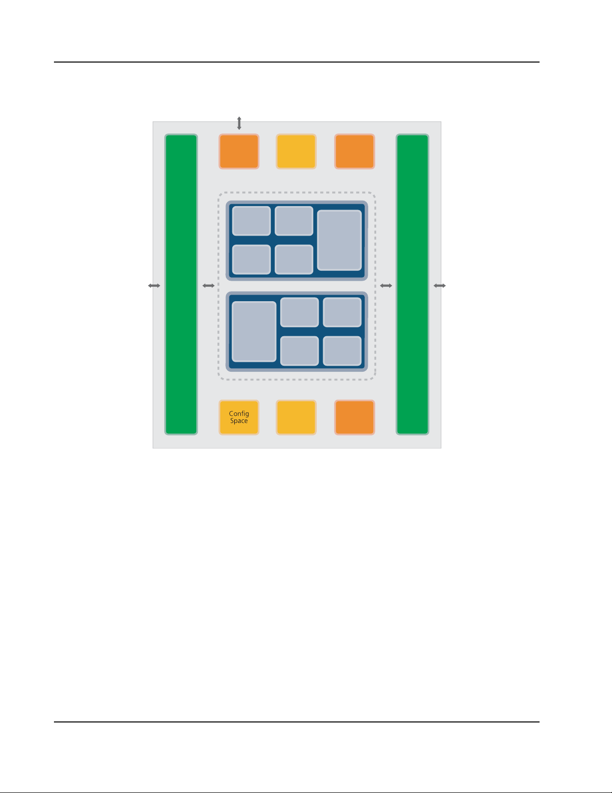
Figure 1: Block Diagram
Secondary PCI Bus Interface
Primary PCI Bus Interface
Secondary
Bus Arbiter
Address
Decoder
Posted
Write
Buffer
Posted
Queue
NonPosted
Buffer
NonPosted
Queue
Mux
Logic
Posted
Write
Buffer
Posted
Queue
Non-
Posted
Buffer
NonPosted
Queue
Mux
Logic
66 MHz / 32-bit
PCI Bus
66 MHz / 32-bit
PCI Bus
80D5000_BK001_02
JTAG
Hot
Swap
Clocking/
Reset
IEEE1149.1
Boundary Scan
1. Functional Overview > Overview of the Tsi350A18
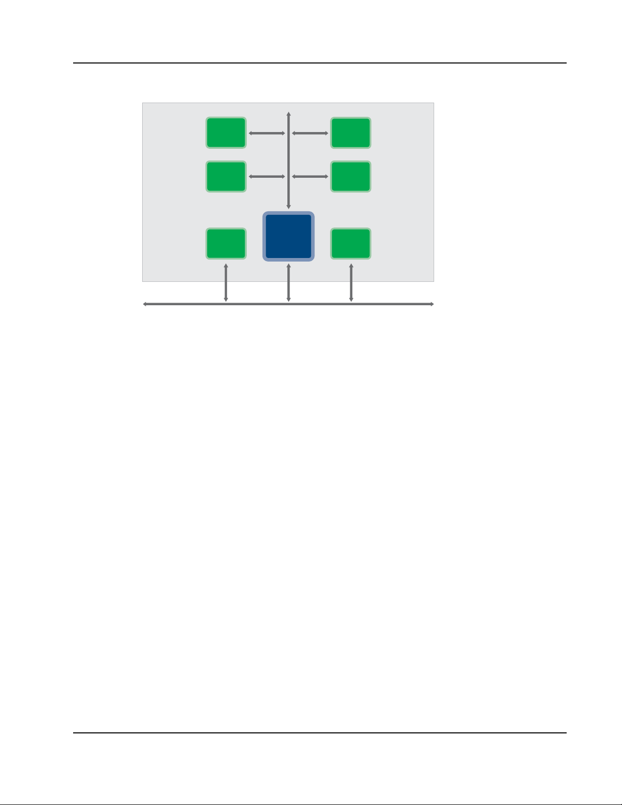
Option card designers can use Tsi350A to implement multiple-device PCI option cards. Without a
PCI-to- PCI bridge, PCI loading rules would limit option cards to one device. The PCI Local Bus
Specification loading rules limit PCI option cards to a single connection per PCI signal in the option
card connector. The Tsi350A overcomes this restriction by providing, on the option card, an
independent PCI bus to which up to nine devices can be attached.
Figure 2 shows how the Tsi350A enables the design of a multi-component option card or expand
existing PCI buses.
Tsi350A User Manual
80D5000_MA001_08
Integrated Device Technology
www.idt.com
Page 19
1. Functional Overview > Overview of the Tsi350A 19
PCI Bus
80D5000_TA001_02
PCI
Device
PCI
Device
PCI
Device
PCI
Device
PCI
Device
PCI
Device
Tsi350A
Figure 2: System Block Diagram
1.1.1 Features
• Industry-standard 32-bit, 66-MHz PCI bridge
•Fully PCI Local Bus Specification, Revision 2.3 compliant
• Supports up to nine PCI bus masters on the secondary interface
• Ten independent secondary clock outputs to the secondary slots
• Primary and secondary interfaces can be operated using asynchronous clocks
• Secondary clock can either be derived from the input primary clock or supplied by an external
clock source
• Secondary clocks can be masked through the GPIO interface during power up
• Supports four independent delayed transactions in each direction
• Supports up to nine secondary requests and grants
• External arbiter support on the secondary bus
• Supports CompactPCI Hot Swap functionality
• C I Power management with D3Hot support with option to disable clocks during D3Hot state
• Supports Bus Locking mechanism
• VGA/Palette memory and I/O decoding options
• Optional non-posted entry flush upon posted writes traveling the same direction
• Compatible with existing solutions from Intel, TI, PLX, and Peri com
Integrated Device Technology
www.idt.com
Tsi350A User Manual
80D5000_MA001_08
Page 20

1.1.2 Compliance
• PCI-to-PCI Bridge Architecture Specification (Revision 1.1)
• PCI Local Bus Specification (Revision 2.3)
• PCI bus Power Management Interface Specification (Revision 1.1)
• Advanced Configuration Power Interface (ACPI)
• PICMG CompactPCI Hot-Swap Specification (Revision 2.0)
1.2 Functional Description
This chapter outlines functionality of various interfaces and major blocks.
1.2.1 PCI Interface
Tsi350A has two PCI interfaces, one on the primary side and another on the secondary side. These
interfaces transfer data/control information to and from BLU (Buffer Logic Unit).
1.2.1.1 Posted Write Buffer
1. Functional Overview > Functional Description20
This buffer is used as temporary storage for posted memory write data flowing from one interface to
the other. Each posted buffer has a capacity of 128 bytes. The amount of buffer locations allotted for a
transaction is dynamic. A single transaction can utilize from one memory location (4 bytes) to 32
memory locations (128 bytes) as needed.
1.2.1.2 Posted Write Queue
Posted Write Queue is used to store control information related to the posted write transaction flowing
from one interface to the other. Each Posted Write Queue is a 4-entry FIFO, providing four active
posted write transactions in each direction. Data related to each entry is stored in the Posted Write
Buffer. Posted Write Queue will accept entry from external master only when at least one entry is free
and at least one Q-word space is available in Posted Write Buffer.
1.2.1.3 Non-Posted Buffer
Non-Posted Buffer is used to hold data for read transactions. Each Non-Posted Buffer contains 128
bytes of buffer space. The amount of buffer locations allotted for a transaction is dynamic. A single
transaction can utilize from one memory location (4 bytes) to 32 memory locations (128 bytes) as
needed. Tsi350A will start giving data on originating bus once the first four locations of the buffer are
filled or the transaction is completed on the target bus.
1.2.1.4 Non-Posted Queue
Non-Posted Queue is used to store the control information related to the all non-posted transactions.
Each Non-Posted Queue is a 4-entry FIFO, providing 4-active non-posted transactions in each
direction. Data related to each entry is stored in the Non-Posted Buffer. The Non-Posted Queue will
accept a transaction from external master only when at least one entry is free.
Tsi350A User Manual
80D5000_MA001_08
Integrated Device Technology
www.idt.com
Page 21

1. Functional Overview > Functional Description 21
1.2.1.5 Mux Logic
This module arbitrates the transactions from the Posted Queue and Non-Posted Queue.
1.2.1.6 Configuration Space
The configuration registers help the system software to configure behavior of the bridge. The bridge
has Type 01 configuration header support as per the specification. All of these registers function
exactly as specified in the PCI to PCI Bridge Architectur e Specification, Revision 1.2. The
configuration space can be accessed only from primary bus interface. Tsi350A implements device
specific configuration registers to enable software to program the bridge features.
1.2.1.7 Address Decoding Logic
Tsi350A operates in transparent mode. In transparent mode I/O, memory, pre-fetchable memory base
and limit, and optional Base Address Registers 0 and 1 define address ranges for the devices residing
on secondary bus. All other addresses are assumed to res ide on the primary bus. Inverse address
decoding determines when to forward a transaction up-stream.
1.2.1.8 Secondary Bus Arbiter
Tsi350A is designed with an internal arbiter that can be enabled through input strap S_CFN_b. The
arbiter provides bus arbitration for nine additional masters. The arbiter can be programmed to
enable/disable and prioritize each request independently through software.
Tsi350A implements 2-level arbitration scheme. The requesters are divided into 2 groups, a high
priority group and a low priority group. Each master can be assigned to either high or low priority
group through the configuration register.
1.2.2 JTAG Controller
Tsi350A provides a JTAG test port that is compliant with IEEE Standard 1149.1, IEEE Standard Test
Access Port and Boundary-Scan Architectur e, to facilitate card and board testing using boundary scan
techniques. This function consists of five-signal test port interface with signals TCK, TDI, TDO, TMS,
and TRST.
1.2.3 Hot Swap Interface
T si350A is designed with an interface for Hot Swap support. This allows the user to insert or extract the
bridge card without powering down the system. During insertion and extraction process, the bridge
indicates to system software about the Hot Swap event by driving HS_EN UM_b. It also provides a
visual indication to the user through the HS_LED signal.
Hot-Swap support is implemented in the 208-pin PQFP package only. The 256-pin PBGA
package does not support Hot Swap.
Integrated Device Technology
www.idt.com
Tsi350A User Manual
80D5000_MA001_08
Page 22

1.3 Architecture
Tsi350A internal architecture consists of the following major functions:
• PCI interface control logic for the primary and secondary PCI interfaces
• Data path and data path control logic
• Configuration register and co nfiguration control logic
• Secondary bus arbiter
1.4 Data Path
The data path consists of a primary-to-secondary data path for transactions and data flowing in the
downstream direction and a secondary-to-primary data path for transactions and data flowing in the
upstream direction.
Both data paths have the following queues:
• Posted write queue
• Delayed transaction queue
1. Functional Overview > Architecture22
• Read data queue
To prevent deadlocks and to maintain da ta coherency, a set of ordering rules is imposed on the
forwarding of posted and delayed transactions across Tsi350A. The queue structure, along with the
order in which the transactions in the queues are initiated and completed, supports these ordering
requirements.
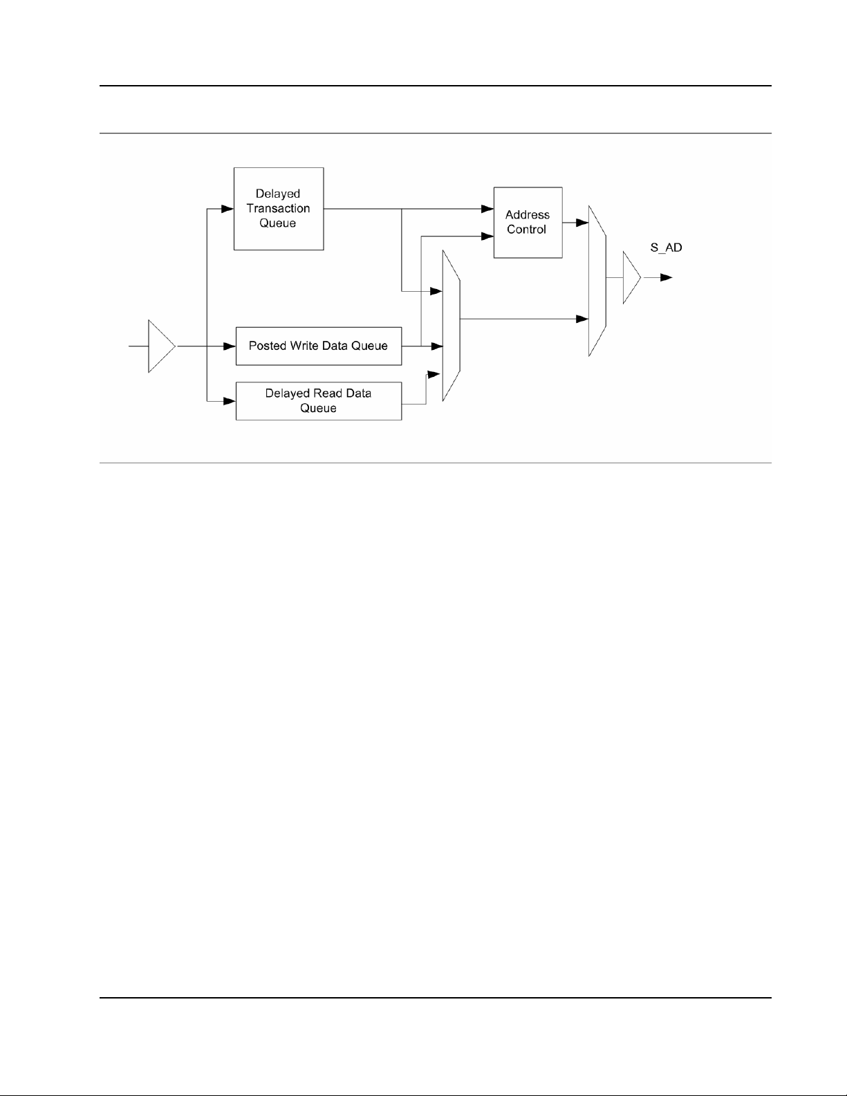
Figure 3 shows the Tsi350A data path for the downstream direction, and the following sections
describe the data path queues.
Tsi350A User Manual
80D5000_MA001_08
Integrated Device Technology
www.idt.com
Page 23
1. Functional Overview > Data Path 23
Figure 3: Tsi350A Downstream Data Path
1.4.1 Posted Write Queue
The posted write queue contains the address and data of memory write transactions targeted for the
opposite interface. The posted write transaction can consist of an arbitrary number of data phases,
subject to the amount of space in the queue and disconnect boundaries. The posted write queue can
contain multiple posted write transactions. The number of posted write transactions that can be queued
at one time is dependent upon their burst size. The posted write queue consists of 128 bytes in each
direction.
1.4.2 Delayed Transaction Queue
For a delayed write request transaction, the delayed transaction queue contains the address, bus
command, 1 Dword of write data, byte enable bits, and parity. When the delayed write transaction is
completed on the target bus, the write completion status is added to the corresponding entry. For a
delayed read request tran sa ctio n, the de laye d tr ansac tion queue c ontains the address and bus c ommand
- and for non-prefetchable read transactions - the byte enable bits. When the delayed read transaction is
completed on the target bus, the read completion status corresponding to that transaction is added to the
delayed request entry. Read data is placed in the read data queue. The delayed transaction queue can
hold up to four transactions (any combination of read and write transactions).
Integrated Device Technology
www.idt.com
Tsi350A User Manual
80D5000_MA001_08
Page 24

1.4.3 Read Data Queue
The read data queue contains read data transferred from the target during a delayed read completion.
Read data travels in the opposite direction of the transaction. The primary-to secondary read data queue
contains read data corresponding to a delayed read transaction residing in the secondary-to-primary
delayed transaction queue. The secondary-to-primary read data queue contains read data corresponding
to a delayed read transaction in the primary-to-secondary delayed transaction queue. The amount of
read data per transaction depends on the amount of space in the queue and disconnect boundaries. Read
data for up to four transactions, subject to the burst size of the read transactions and available queue
space, can be stored. The read data queue for Tsi350A consists of 128 bytes in each direction.
1. Functional Overview > Data Path24
Tsi350A User Manual
80D5000_MA001_08
Integrated Device Technology
www.idt.com
Page 25

2. PCI Interface
This chapter discusses the following topics:
• “Transaction Types” on page 25
• “Transaction Phases” on page 27
• “Write Transactions” on page 28
• “Read Transactions” on page 32
• “Configuration Transactions” on page 37
• “Transaction Termination” on page 42
2.1 Transaction Types
This section summarizes the PCI transactions performed by Tsi350A.
25
Table 1 lists the command code and name of each PCI transaction. The Master and Target columns
indicate Tsi350A support for each transaction when Tsi350A initiates transactions as a master, on the
primary bus and on the secondary bus, and when Tsi350A responds to transactions as a target, on the
primary bus and on the secondary bus.
As indicated in Table 1, the following PCI commands are not supported by Tsi350A:
• Tsi350A never initiates a PCI transaction with a reserved command code and, as a target Tsi350A
ignores reserved command codes.
• Tsi350A never initiates an interrupt acknowledge transaction and, as a target, Tsi350A ignores
interrupt acknowledge transactions. Interrupt acknowledge transactions are expected to reside
entirely on the primary PCI bus closest to the host bridge.
• Tsi350A does not respond to special cycle transactions. Tsi350A cannot guarantee delivery of a
special cycle transaction to downstream buses because of the broadcast nature of the special cycle
command and the inability to control the transaction as a target. To generate special cycle
transactions on other PCI buses, either upstream or downstream, a Type 1 configuration command
must be used.
Integrated Device Technology
www.idt.com
Tsi350A User Manual
80D5000_MA001_08
Page 26

• Tsi350A does not generate Type 0 configuration transactions on the primary interface, nor does it
respond to Type 0 configuration transactions on the secondary PCI interface. The PCI-to-PCI
Bridge Architecture Specification does not support configuration from the secondary bus.
Table 1: Tsi350A PCI Transactions
2. PCI Interface > Transaction Types26
Initiates as a Master Responds as a Target
Command Type of Transaction
0000 Interrupt Acknowledge No No No No
0001 Special Cycle Yes Yes No No
0010 I/O Read Yes Yes Yes Yes
0011 I/O Write Yes Yes Yes Yes
0100 Reserved No No No No
0101 Reserved No No No No
0110 Memory Read Yes Yes Yes Yes
0111 Memory Write Yes Yes Yes Yes
1000 Reserved No No No No
1001 Reserved No No No No
1010 Configuration read No Yes Yes No
1011 Configuration Write Type 1 Yes Yes Type 1
1100 Memory Read Multiple Yes Yes Yes Yes
1101 Dual Address Cycle Yes Yes Yes Yes
Primary Secondary Primary Secondary
1110 Memory Read Line Yes Ye s Yes Yes
1111 Memory Write and Invalidate Yes Yes Yes Yes
Tsi350A User Manual
Integrated Device Technology
80D5000_MA001_08
www.idt.com
Page 27

2. PCI Interface > Transaction Phases 27
2.2 Transaction Phases
2.2.1 Address Phase
The standard PCI transaction consists of one or two address phases, followed by one or more data
phases. An address phase always lasts one PCI clock cycle. The first address phase is designated by an
asserting (falling) edge on the FRAME_b signal. The number of address phases depends on whether
the address is 32 bits or 64 bits.
2.2.1.1 Single Address Phase
A 32-bit address uses a single address phase. This address is driven on AD[31:0], and the bus
command is driven on C/BE_b[3:0]. Tsi350A supports the linear increment address mode only, which
is indicated when the lower two address bits are equal to 0. If either of the lower two address bits is
nonzero, T si350A automatically disconnects the transaction after the first data transfer.
2.2.1.2 Dual Address Phase
Dual address transactions are PCI transactions that contain the following two address phases specifying
a 64-bit address:
• The first address phase is denoted by the asserting edge of FRAME_b.
• The second address phase always follows on the next clock cycle.
The first address phase contains the dual address command code on the C/BE_b[3:0] lines, and the low
32 address bits on the AD[31:0] lines. The second address phase consists of the specific memory
transaction command code on the C/BE_b[3:0] lines and the high 32 address bits on the AD[31:0]lines.
In this way, 64-bit addressing can be supported on 32-bit PCI buses.
The PCI-to-PCI Bridge Architecture Specification supports the use of dual address transactions in the
prefetchable memory range only. Tsi350A supports dual address transactions in both the upstream and
the downstream direction. Tsi350A supports a programmable 64-bit address range in prefetchable
memory for downstream forwarding of dual address transactions. Dual address transactions falling
outside the prefetchable address range are forwarded upstream, but not downstream. Prefetching and
posting are performed in a manner consistent with the guidelines given in this specification for each
type of memory transaction in prefetchable memory space.
Any memory transactions addressing the first 4 GB space should use a single address phase; that is, the
high 32 bits of a dual address transaction should never be 0.
Tsi350A responds only to dual address transactions that use the following transaction command codes:
• Memory Write
• Memory Write and Invalidate
• Memory Read
• Memory Read Line
Integrated Device Technology
www.idt.com
Tsi350A User Manual
80D5000_MA001_08
Page 28

• Memory Read Multiple
Use of other transaction codes may result in a master abort.
2.2.1.3 Device Select (DEVSEL_b) Generation
T si350A always performs positive address dec oding when accepting tran sactions on either the primary
or secondary buses. Tsi350A never subtractively decodes. Medium DEVSEL_b timing is used on both
interfaces.
2.2.2 Data Phase
The address phase or phases of a PCI transaction are followed by one or more data phases. A data
phase is completed when IRDY_b and either TRDY_b or STOP_b are asserted. A transfer of data
occurs only when both IRDY_b and TRDY_b are asserted during the same PCI clock cycle. The last
data phase of a transaction is indicated when FRAME_b is de-asserted and both TRDY_b and IRDY_b
are asserted, or when IRDY_b and STOP_b are asserted (se e “T rans action Termination” o n page 42 for
further discussion of transaction termination).
Depending on the command type, Tsi350A can support multiple data phase PCI transactions. For a
detailed description of how Tsi350A imposes disconnect boundaries, see “Write Transactions” on
page 28 for a description of write address boundaries and “Read Transactions” on page 32 for a
description of read address boundaries.
2. PCI Interface > Write Transactions28
2.3 Write Transactions
Write transactions are treated as either posted write or delayed write transactions.
2.3.1 Posted Write Transactions
Posted write forwarding is used for memory write and for memory write and invalidate transactions.
When Tsi350A determines that a memory write transaction is to be forwarded across the bridge,
T si350A asserts DEVSEL_b wit h medium timing and TRDY_b in the next cy cle, provided th at enough
buffer space is available in the posted data queue for the address and at least 8 Dwords of data. This
enables Tsi350A to accept write data without obtaining access to the target bus. Tsi350A can accept
one Dword of write data every PCI clock cycle; that is, no target wait states are inserted. This write
data is stored in internal posted write buffers and is subsequently delivered to the target.
Tsi350A continues to accept write data until one of the following events occurs:
• The initiator terminates the transaction by de-asserting FRAME_b and IRDY_b.
• An internal write address boundary is reached, such as a cache line boundary or an aligned 4 kB
boundary, depending on the transaction type.
• The posted write data buffer fills up.
Tsi350A User Manual
80D5000_MA001_08
Integrated Device Technology
www.idt.com
Page 29

2. PCI Interface > Write Transactions 29
When one of the last two events occurs, Tsi350A retur ns a target disconnect to the requesting initiator
on this data phase to terminate the transaction. Once the posted write data moves to the head of the
posted data queue, Tsi350A asserts its request on the target bus. This can occur while Ts i350A is still
receiving data on the initiator bus. When the grant for the target bus is received and the target bus is
detected in the idle condition, Tsi350A asserts FRAME_b and drives the stored write address out on the
target bus. On the following cycle, Tsi350A drives the first Dword of write data and continues to
transfer write data until all write data corresponding to that transaction is delivered, or until a target
termination is received. As long as write data exists in the queue, Tsi350A can drive 1 Dword of write
data each PCI clock cycle.
Tsi350A ends the transaction on the target bus when one of the following conditions is met:
• All posted write data has been delivered to the target.
• The target returns a target disconnect or target retry (Tsi350A starts another transaction to deliver
the rest of the write date)
• The target returns a target abort (Tsi350A discards remaining write data).
• The master latency timer expires, and Tsi350A no longer has the target bus grant (Tsi350A starts
another transaction to deliver remaining write data).
2.3.2 Memory Write and Invalidate Transactions
Posted write forwarding is used for memory write and invalidate transactions. Memory write and
invalidate transactions guarantee transfer of entire cache lines. If the write buffer fills before an entire
cache line is transferred, Tsi350A disconnects the transaction and converts it to a memory write
transaction.
Tsi350A disconnects memory write and invalidate co m mand s at aligned cache line boundaries. The
cache line size value in Tsi350A cache line size register gives the number of Dwords in a cache line.
For Tsi350A to generate memory write and invalidate transactions, this cache line size value must be
written to a value that is a nonzero power of two and less than or equal to 16 (that is, 1, 2, 4, 8, or 16
Dwords).
If the cache line size does not meet the memory write and invalidate conditions, that is, the value is 0 or
is not a power of two or is greater than 16 Dwords, Tsi350A treats the memory write and invalidate
command as a memory write command. In this case, when Tsi350A forwards the memory write and
invalidate transaction to the target bus, it converts the command code to a memory write code and does
not observe cache line boundaries.
If the value in the cache line size register does meet the memory write and invalidate conditions, that is,
the value is a nonzero power of 2 less than or equal to 16 Dwords, T si350A returns a target disconnect
to the initiator either on a cache line boundary or when the posted write buffer fills. For a cache line
size of 16 Dwords, Tsi350A disconnects a memory write and invalidate transaction on every cache line
boundary. When the cache line size is 1, 2, 4, or 8 Dwords, Tsi350A accepts another cache line if at
least 8 Dwords of empty space remains in the posted write buffer. If less than 8 Dwords of empty space
remains, Tsi350A disconnects on that cache line boundary. When the memory write and invalidate
transaction is disconnected before a cache line boundary is reached, typically because the posted write
buffer fills, the transaction is converted to a memory write transaction.
Integrated Device Technology
www.idt.com
Tsi350A User Manual
80D5000_MA001_08
Page 30

2.3.3 Delayed Write Transactions
Delayed write forwarding is used for I/O write transactions and for Type 1 configuration write
transactions.
A delayed write transaction guarantees that the actual target response is returned back to the initiator
without holding the initiating bus in wait states. A delayed write transaction is limited to a single
Dword data transfer.
When a write transaction is first detected on the initiator bus, and Tsi350A forwards it as a delayed
transaction, Tsi350A claims the access by asserting DEVSEL_b and returns a target retry to the
initiator. During the address phas e, Tsi350A samples the bus command, address, and address parity one
cycle later. After IR DY_b is assert ed, Tsi350A also samples the fir st da ta Dword, byte enable bits , and
data parity. This information is placed into the delayed transaction queue. The transaction is queued
only if no other existing delayed transactions have the same address and command, and if the delayed
transaction queue is not full. When the delayed write transaction moves to the head of the delayed
transaction queue and all ordering constraints with posted data are satisfied, Ts i350A initiates the
transaction on the target bus. Tsi350A transfers the write data to the target. If Tsi350A receives a target
retry in response to the write transaction on the target bus, it continues to repeat the write transaction
until the data transfer is completed, or until an error condition is encoun tered.
If Tsi350A is unable to deliver write data after 2
returns a target abort to the initiator. The delayed transaction is removed from the delayed transaction
queue. Tsi350A also asserts P_SERR_b if the primary SERR_b enable bit is set in the command
register.
2. PCI Interface > Write Transactions30
24
attempts, Tsi350A ceases further write attempts and
When the initiator repeats the same write transaction (same command, address, byte enable bits, and
data), and the completed delayed transaction is at the head of the queue, Tsi350A claims the access by
asserting DEVSEL_b and returns TRDY_b to the initiator to indicate that the write data was
transferred. If the initiator requests multiple Dwords, Tsi350A also asserts STOP_b in conjunction with
TRDY_b to signal a target disconnect. Note that only those bytes of write data with valid byte enable
bits are compared. If any of the byte enable bits are turned off (driven high), the corresponding byte of
write data is not compared.
If the initiator repeats the write transaction before the data has been transferred to the target, Tsi350A
returns a target retry to the initiator. Tsi350A continues to return a target retry to the initiator until write
data is delivered to the target, or until an error condition is encountered. When the write transaction is
repeated, Tsi350A does not make a new entry into the delayed transaction queue. For detailed
information on how the Tsi350A responds to target termination during delayed write transactions, see
“Delayed Write Target Termination Response” on page 44.
Tsi350A
implements a discard timer that starts counting when the delayed write completion is at the
head of the delayed transaction queue. The initial value of this timer can be set to one of two values,
selectable through both the primary and secondary master time-out bits in the bridge control register . If
the initiator does not repeat the delayed write transaction before the discard timer expires, Tsi350A
discards the delayed write transaction from the delayed transaction queu e and asserts P_SERR_b (if
enabled).
Tsi350A User Manual
80D5000_MA001_08
Integrated Device Technology
www.idt.com
Page 31

2. PCI Interface > Write Transactions 31
2.3.4 Write Transaction Address Boundaries
Tsi350A imposes internal address boundaries when accepting write data. The aligned address
boundaries are used to prevent Tsi350A from continuing a transaction over a device address boundary
and to provide an upper limit on maximum latency. Tsi350A returns a target disconnect to the initiator
when it reaches the aligned address boundaries under the conditions show n in Table 2.
Table 2: Write Transaction Address Boundaries
Type of
Transaction
Condition Aligned Address Boundary
Memory Write Disconnect control bit = 0
(“Chip Control Register—Offset
0x40” on page 152)
Memory Write Disconnect control bit = 1
(“Chip Control Register—Offset
0x40” on page 152)
Memory Write
and Invalidate
Memory Write
and Invalidate
Memory Write
and Invalidate
Cache line size = 1, 2, 4, 8, 16
(“Cache Line Size Register—Offset
0x0C” on page 135)
Cache line size = 1, 2, 4, 8
(“Cache Line Size Register—Offset
0x0C” on page 135)
Cache line size = 16
(“Cache Line Size Register—Offset
0x0C” on page 135)
2.3.5 Buffering Multiple Write Transactions
T si350A continues to accept posted memory wr ite transactions as long as space for at least 1 Dword of
data in the posted write data buffer remains. If the posted write data buffer fills before the initiator
terminates the write transaction, Tsi350A returns a target disconnect to the initiator.
4 kB aligned address boundary
Disconnects at n
4 kB aligned address boundary
nth cache line boundary, where a cache line
boundary is reached and less than 8 free D-words of
posted write buffer space remains
16-Dword aligned address boundary
th
cache line boundary
Delayed write transactions are handled as long as at least one open entry in Tsi350A delayed
transaction queue exists. Therefore, several posted and delayed write transactions can exist in data
buffers at the same time.
2.3.5.1 Fast Back-to-Back Write Transactions
T si350A can recognize fast back-to-back write trans actions as a target on the PCI bus. When the bridge
experiences shortage of buffer space, the fast back-to-back transaction will be retired.
Tsi350A does not perform write combining or merging.
Integrated Device Technology
www.idt.com
Tsi350A User Manual
80D5000_MA001_08
Page 32

2.4 Read Transactions
Delayed read forwarding is used for all read transactions crossing Tsi350A.Delayed read transactions
are treated as either prefetchable or non-prefetchable.
Prefetching is a useful technique for hiding the latency of a burst read transaction but its use is
restricted. Memory that is prefetchable has the attribute that it returns the same data when read multiple
times and does not alter any other device state when it is read. It is the responsibility of the target
device to disconnect a burst transaction when either a Base Address register boundary is reached, or a
boundary is reached within a Base Address register where the attributes of the access change (i.e.,
prefetchable vs. non-prefetchable). When prefetching, the bridge may read data that is not consumed
by the master. The bridge is required to discard any prefetched read data not consumed when the
master concludes the read transa c tion
A bridge may safely prefetch data when the transaction uses the Memory Read Line or Memory Read
Multiple command. Since most processor architectures do not have the notion of prefetchable memory ,
typical host bus bridges do not generate Memory Read Line or Memory Read Multiple transactions. A
bridge may provide an optional address range that allows the bridge to prefetch memory read data from
a target attached to the secondary interface of the bridge.
A bridge is permitted to prefetch data from a secondary bus if the transaction originates on the primary
bus and is either a Memory Read Line or Memory Read Multiple command. A bridge is permitted to
prefetch data from the primary bus if the transaction originates on the secondary bus and is either a
Memory Read Line or Memory Read Multiple command. Masters attached to the secondary interface
of a bridge are encouraged to use the Memory Read Line or Memory Read Multiple commands if they
desire high performance read transactions. The bridge is also permitted to assume that all transactions
that originate on the secondary bus and go up through the bridge have a final destination at main
memory and therefore are prefetchable. When prefetching memory read data, the bridge is permitted to
assert all byte enables for all data phases on the destination bus independent of the byte enables used by
the originating bus master.
2. PCI Interface > Read Transactions32
Table 3 shows the read behavio r, prefetchable or non-prefetchable, for each type of read operation.
T able 3: Read Transaction Prefetching
Type of Transaction Read Behavior
I/O read Prefetching never done
Configuration read Prefetching never done
Memory read Downstream: Prefetching used if address in prefetchable
Memory read line Prefetching always used
Memory read multiple Prefetching always used
Tsi350A User Manual
80D5000_MA001_08
Upstream: Prefetching used if prefetch disable is off (default).
Integrated Device Technology
www.idt.com
Page 33

2. PCI Interface > Read Transactions 33
2.4.1 Calculating the Prefetch Count
Tsi350A implements following registers to calculate prefetch count:
• “Cache Line Size Register—Offset 0x0C” on page 135
• “Read Transaction Control Register— Offset 0x 4 4” on page 155
The bits in the listed registers are used to calculate the prefetch count using the following equation:
• When the Downstream Cacheline Prefetch Enable bit and the Upstream Cacheline Prefetch Enable
bit in the“Read Transaction Control Register— Offset 0x44” on page 155 are 0:
— PRE_DW_CNT = (MPC - CLS) + CLB_CNT
—Where:
– PRE_DW_CNT is the prefetch dword count
– MPC is the Maximum Prefetch Count field in the Read Transaction Control Register
– CLS is the Cache Line Size field in the Cacheline Size Register
– CLB_CNT is the Cache Line Boundary Count
• When the Downstream Cacheline Prefetch Enable bit and the Upstream Cacheline Prefetch Enable
bit in the“Read Transaction Control Register— Offset 0x44” on page 155 are set to 1:
— PRE_DW_CNT = (MPC - CLS) + CLB_CNT
—Where:
– PRE_DW_CNT is the prefetch dword count
– MPC is the Maximum Prefetch Count field in the Read Transaction Control Register
– CLS is the Cache Line Size field in the Cacheline Size Register
– CLB_CNT is the Cache Line Boundary Count
If the prefetch count has not reached the calculated prefetch count and flow through has been achieved,
the Ts i350A keeps prefetching until one of the following occurs:
• The requesting master terminates the transaction
• Read data FIFO becomes full
• The read transaction reaches the 4 K address boundary
• A target disconnects the ongoing transaction
The following rules are true when determining the prefetch co unt be havio ur of the Tsi350A:
• If the maximum prefetch count is programmed less than Cache Line Size, the Tsi350A prefetches
data up to first cache line boundary.
• Based on the formula, prefetch count is no less than 16 Dword count for any combination of cache
line size and maximum prefetch count.
• If buffer is empty, Tsi350A can prefetch more than calculated prefetch count.
• By default, the T s i350 prefetches data up to cache line boundary. User must program bits 2 and 1 at
offset 0x44 to zero to enable maximum prefetch count registers (7:6 and 5:4).
Integrated Device Technology
www.idt.com
Tsi350A User Manual
80D5000_MA001_08
Page 34

• For single D-word read transactions prefetching is ignored.
• In the case where there is a single request pending in the buffers and flow-through is established,
the maximum prefetch count value programmed at offset 0x44 is ignored
2.4.2 Prefetchable Read Transactions
A prefetchable read transaction is a read transaction where the Tsi350A performs speculative Dword
reads, transferring data from the target before it is requested from the initiator. This behavior allows a
prefetchable read transaction to consist of multiple data transfers. However, byte enable bits cannot be
forwarded for all data phases as is done for the single data phase of the non-prefetchable read
transaction.
Prefetchable behavior is used for memory read line and memory read multiple transactions, as well as
for memory read transactions that fall into prefetchable memory space.
The amount of data that is prefetched depends on the type of transaction. The amount of prefetching
may also be affected by the amount of free buffer space available in the Tsi350A, and by any read
address boundaries encountered.
2.4.3 Non-Prefetchable Read Transactions
2. PCI Interface > Read Transactions34
A non-prefetchable read transaction is a read transaction where the Tsi350A requests 1–and only
1–Dword from the target and disconnects the initiator after delivery of the first Dword of read data.
Unlike prefetchable read transactions, the Tsi350A
data phase.
Non-prefetchable behavior is used for I/O and configuration read transactions, as well as for memory
read transactions that fall into non-prefetchable memory space. If extra read transactions could have
side effects, for example, when accessing a FIFO, use non-prefetchable read transactions to those
locations. Accordingly, if it is important to retain the value of the byte enable bits during the data
phase, use non-prefetchable read transactions. If these locations are mapped in memory space, use the
memory read command and map the target into non-prefetchable (memory-mapped I/O) memor y space
to utilize non-prefetching behavior.
2.4.4 Read Prefetch Address Boundaries
T si350A has internal read address boundaries on read prefetching. When a read transaction reaches one
of these aligned address boundaries, Tsi350A stops prefetching data, unless the target signals a target
disconnect before the read prefetch boundary is reached. When Tsi350A finishes transferring this read
data to the initiator, it returns a target disconnect with the last data transfer, unless the initiator
completes the transaction before all prefetched read data is delivered. Any leftover prefetched data is
discarded.
Prefetchable read transactions in flow-through mode prefetch to the nearest aligned 4 kB address
boundary, or until the initiator de-asserts FRAME_b. “Delayed Read Completion on Initiator Bus ” on
page 36 describes flow-through mode during read operations.
forwards the read byte enable information for the
Tsi350A User Manual
80D5000_MA001_08
Integrated Device Technology
www.idt.com
Page 35

2. PCI Interface > Read Transactions 35
Table 4 shows the read prefetch address boundaries for read transactions during non-flow-through
mode.
Table 4: Read Prefetch Address Boundaries
Type of Transaction Address Space Cache Line Size Prefetch Aligned Address Boundary
Configuration read -- -- One Dword (no prefetch)
I/O read -- -- One Dword (no prefetch)
Memory read Non-prefetchable -- One Dword (no prefetch)
Memory read Prefetchable CLS 1, 2, 4, 8 16-Dword aligned address boundary
Memory read Prefetchable CLS = 1, 2, 4, 8 Cache line address boundary
Memory read line -- CLS 1, 2, 4, 8 16-Dword aligned address boundary
Memory read line -- CLS = 1, 2, 4, 8 Cache line address boundary
Memory read multiple -- CLS 1, 2, 4, 8 Queue full
Memory read multiple -- CLS = 1, 2, 4, 8 Second cache line boundary
2.4.5 Delayed Read Requests
Tsi350A treats all read transactions as delayed read transactions, which means that the read request
from the initiator is posted into a delayed transaction queue. Read data from the target is placed in the
read data queue and is transferred to the initiator when the initiator repeats the read transaction.
When T si350A accepts a delayed read request, it first samples the read address, read bus command, and
address parity. When IRDY_b is asserted, Tsi350A then samples the byte enable bits for the first data
phase. This information is entered into the delayed transaction queue. Tsi350A terminates the
transaction by signaling a target retry to the initiator. Upon reception of the target retry, the initiat or is
required to continue to repeat the same read transaction until at least one data transfer is completed, or
until a target response other than target retry (target abort, or master abort) is received.
2.4.5.1 Delayed Read Completion with Target
When the delayed read request reaches the head of the delayed transaction queue, and all previously
queued posted write transactions have been delivered, T si350A arbitrates for the tar get bus and initiates
the read transaction, using the exact read address and read command captured from the init iator during
the initial delayed read request. If the read transaction is a non-prefetchable read, Tsi350A drives the
captured byte enable bits during the next cycle. If the transaction is a prefetchable read transaction, it
drives the captured byte enables for first data phase and drives all byte enable bits to 0 for all remaining
data phases. If Tsi350A receives a target retry in response to the read transaction on the target bus, it
continues to repeat the read transaction until at least one data transfer is completed, or until an error
condition is encountered. If the transaction is terminated via normal master termination or target
disconnect after at least one data transfer has been comp leted, Tsi350A does not initiate any further
attempts to read more data.
Integrated Device Technology
www.idt.com
Tsi350A User Manual
80D5000_MA001_08
Page 36

If Tsi350A is unable to obtain read data from the target after 224 attempts, Tsi350A ceases further read
attempts and returns a target abort to the initiator. The delayed transaction is removed from the delayed
transaction queue. Tsi350A also asserts P_SERR_b if the primary SERR_b enable bit is set in the
command register.
Once Tsi350A receives DEVSEL_b and TRDY_b from the target, it transfers the data read to the
opposite direction read data queue, pointing toward the opposite interface, before terminating the
transaction. For example, read data in response to a downstream read transaction initiated on the
primary bus is placed in the upstream read data queue. Tsi350A can accept 1 Dword of read data each
PCI clock cycle; that is, no master wait states are inserted. The number of Dwords transferred during a
delayed read transaction depends on the conditions given in Table 4 on page 35 (assuming no
disconnect is received from the target).
2.4.5.2 Delayed Read Completion on Initiator Bus
When the transaction has been completed on the target bus, and the delayed read data is at the head of
the read data queue, and all ordering constraints with posted write transactions have been satisfied,
Tsi350A transfers the data to the initiator when the initiator repeats the transaction. For memory read
transactions, Tsi350A aliases the memory read, memory read line, and memory read multiple bus
commands when matching the bus command of the transaction to the bus command in the delay e d
transaction queue. Tsi350A returns a tar get disconnect along with the transfer of the last Dword of read
data to the initiator. If the initiator terminates the transaction before all read data has been transferred,
the remaining read data left in data buffers is discarded.
2. PCI Interface > Read Transactions36
When the master repeats the transaction and starts transferring prefetchable read data from Tsi350A
data buffers while the read transaction on the target bus is still in progress and before a read boundary
is reached on the target bus, the read transaction starts operating in flow-through mode. Because data is
flowing through the data buffers from the target to the initiator, long read bursts can then be sustained.
In this case, the read transaction is allowed to continue until the initiator terminates the transaction, or
until an aligned 4 kB address boundary is reached, or until the buffer fills, whichever comes first. When
the buffer empties, Tsi350A reflec ts the stalled condition to the initiator by de-asserting TRDY_b until
more read data is available; otherwise, Tsi350A does not insert any target wait states. When the
initiator terminates the transaction, the de-assertion of FRAME_b on the initiator bus is forwarded to
the target bus. Any remaining read data is discarded.
Tsi350A implements a discard timer that starts counting when the delayed read completion is at the
head of the delayed transaction queue, and the read data is at the head of the read data queue. The initial
value of this timer can be set to one of two values, selectable through both the primary and secondary
master time-out value bits in the bridge control reg ist er. If the initiator does not repeat the read
transaction before the discard timer expires Tsi350A discards the read transaction and the read data
from its queues. Tsi350A also conditionally asserts P_SERR_b.
Tsi350A has the capability to post multiple delayed read requests, up to a maximum of three in each
direction. If an initiator starts a read transaction that matches the address and read command of a read
transaction that is already queued, the current read command is not posted as it is already contained in
the delayed transaction queue.
Tsi350A User Manual
80D5000_MA001_08
Integrated Device Technology
www.idt.com
Page 37

2. PCI Interface > Configuration Transactions 37
2.5 Configuration Transactions
Configuration transactions are used to initialize a PCI system. Every PCI device has a configuration
space that is accessed by configuration commands. All Tsi350A registers are accessible in
configuration space only.
In addition to accepting configuration transactions for initialization of its own configuration space,
Tsi350A also forwards configuration transactions for device initialization in hierarchical PCI systems,
as well as for special cycle generation.
To support hierarchical PCI bus systems, two types of configuration trans actions are specified: Type 0
and Type 1.
Type 0 configuration transactions are issued when the intended target resides on the same PCI bus as
the initiator. A Type 0 configuration transaction is identified by the configuration command and the
lowest 2 bits of the address set to 00b.
Type 1 configuration transactions are issued when the intended target resides on another PCI bus , or
when a special cycle is to be generated on another PCI bus. A Type 1 configuration command is
identified by the configuration command and the lowest 2 address bits set to 01b.
Figure 4 and Figure 5 show the address formats for Type 0 and Type 1 configuration transactions.
Figure 4: Type 0 Configuration Transaction
31 11 10 8 7 2 1 0
Reserved Function
number
Register
number
00
Figure 5: Type 1 Configuration Transaction
31 24 23 16 15 11 10 8 7 2 1 0
Reserved Bus number Device number Function
number
Register
number
01
The Register Number field appears in both Type 0 and Type 1 formats and addresses the configuration
register to be accessed. The Function Number appears in both Type 0 and Type 1 formats and indicates
the function within a multifunction device being accessed. For single function devices, this value is not
decoded. Type 1 configuration transaction addresses also include a 5-bit field designating the device
number that identifies the device on the target PCI bus that is to be accessed. In addition, the bus
number in Type 1 transactions specifies the PCI bus to which the transaction is targeted.
Integrated Device Technology
www.idt.com
Tsi350A User Manual
80D5000_MA001_08
Page 38

2.5.1 Type 0 Access to Tsi350A
Tsi350A configuration space is accessed by a Type 0 configuration transaction on the primary
interface. Tsi350A configuration space cannot be accessed from the secondary bus. Tsi350A responds
to a Type 0 configuration transaction by asserting P_DEVSEL_b when the following conditions are
met during the address phase:
• The bus command is a configuration read or configuration write transaction.
• Low 2 address bits P_AD[1:0] must be 00b.
• Signal P_IDSEL must be asserted.
The function code is ignored because Tsi350A is a single-function device.
Tsi350A limits all configuration accesses to a single Dword data transfer and returns a target
disconnect with the first data transfer if additional data phases are requested. Because read transactions
to T si350A configuration space do not have side effects, all bytes in the requested Dword are returned,
regardless of the value of the byte enable bits.
Type 0 configuration write and read transactions do not use Tsi350A data buffers; that is,
these transactions are completed immediately, regardless of the state of the data buffers.
2. PCI Interface > Configuration Transactions38
Tsi350A ignores all Type 0 transactions initiated on the secondary interface.
2.5.2 Type 1 to Type 0 Translation
Type 1 configuration transactions are used specifically for device configuration in a hierarchical PCI
bus system. A PCI-to-PCI bridge is the only type of device that should respond to a Type 1
configuration command. Type 1 configuration commands are used when the configuration access is
intended for a PCI device that resides on a PCI bus other than the one where the Type 1 transaction is
generated.
Tsi350A performs a Type 1 to Type 0 translation when the Type 1 transaction is generated on the
primary bus and is intended for a device attached directly to the secondary bus. Tsi350A must convert
the configuration command to a T ype 0 format so that the secondary bus device can respond to it. Type
1 to Type 0 translations are performed only in the downstream direction; that is, Tsi350A generates a
Type 0 transaction only on the secondary bus, and never on the primary bus.
Tsi350A responds to a Type 1 configuration transaction and translates it int o a Type 0 transaction on
the secondary bus when the following conditions are met during the address phase:
• The lower two address bits on P_AD[1:0] are 01b.
• The bus number in address field P_AD[23:16] is equal to the value in the secondary bus number
register in Tsi350A configuration space.
The bus command on P_CBE_b[3:0] is a configuration read or configuration write transaction. When
Tsi350A translates the Type 1 transaction to a Type 0 transaction on the secondary interface, it
performs the following translations to the address:
• Sets the low two address bits on S_AD[1:0] to 00b.
Tsi350A User Manual
80D5000_MA001_08
Integrated Device Technology
www.idt.com
Page 39

2. PCI Interface > Configuration Transactions 39
• Decodes the device number and drives the bit pattern specified in Table 5 on S_AD[31:16] for the
purpose of asserting the device’s IDSEL signal.
• Sets S_AD[15:11] to 0.
• Leaves unchanged the functio n number and register number fields.
• Tsi350A asserts a unique address line based on the device number. These address lines may be
used as secondary bus IDSEL signals. The mapping of the address lines depends on the device
number in the Type 1 address bits P_AD[15:11], as shown in Table 5.
Table 5 shows the mapping used by the Tsi350A.
Table 5: Device Number to IDSEL S_AD Pin Mapping
Device Number P_AD[15:11] Secondary IDSEL S_AD[31:16] S_AD Bit
0h 00000 0000 0000 0000 0001 16
1h 00001 0000 0000 0000 0010 17
2h 00010 0000 0000 0000 0100 18
3h 00011 0000 0000 0000 1000 19
4h 00100 0000 0000 0001 0000 20
5h 00101 0000 0000 0010 0000 21
6h 00110 0000 0000 0100 0000 22
7h 00111 0000 0000 1000 0000 23
8h 01000 0000 0001 0000 0000 24
9h 01001 0000 0010 0000 0000 25
Ah 01010 0000 0100 0000 0000 26
Bh 01011 0000 1000 0000 0000 27
Ch 01100 0001 0000 0000 0000 28
Dh 01101 0010 0000 0000 0000 29
Eh 01110 0100 0000 0000 0000 30
Fh 01111 1000 0000 0000 0000 31
10h-1Eh 10000-11110 0000 0000 0000 0000 -1Fh 11111 Generate special cycle (P_AD[7:2] = 00h)
0000 0000 0000 0000 (P_AD[7:2] 00h)
--
Integrated Device Technology
www.idt.com
Tsi350A User Manual
80D5000_MA001_08
Page 40

2. PCI Interface > Configuration Transactions40
Tsi350A can assert up to 16 unique address lines to be used as IDSEL signals for up to 16 devices on
the secondary bus, for device numbers ranging from 0 through 15. Because of electrical loading
constraints of the PCI bus, more than 16 IDSEL signals should not be necessary. However, if device
numbers greater than 15 are desired, some external method of generating IDSEL lines must be used,
and no upper address bits are then asserted. The configuration transaction is still translated and passed
from the primary bus to the secondary bus. If no IDSEL pin is asserted to a secondary device, the
transaction ends in a master abort.
Tsi350A forwards Type 1 to Type 0 configuration read or write transactions as delayed
transactions. Type 1 to Type 0 configuration read or write transactions are limited to a single
32-bit data transfer.
Tsi350A User Manual
80D5000_MA001_08
Integrated Device Technology
www.idt.com
Page 41

2. PCI Interface > Configuration Transactions 41
2.5.3 Type 1 to Type 1 Forwarding
T ype 1 to Type 1 transaction forwarding provides a hierarchical configuration mechanism when two or
more levels of PCI-to-PCI bridges are used.
When Tsi350A detects a Type 1 configuration transaction intended for a PCI bus downstream from the
secondary bus, Tsi350A forwards the transaction unchanged to the secondary bus. Ultimately, this
transaction is translated to a Type 0 configuration command or to a special cycle transaction by a
downstream PCI-to-PCI bridge. Downstream Type 1 to Type 1 forwarding occurs when the following
conditions are met during the address phase:
• The low 2 address bits are equal to 01b.
• The bus number falls in the range defined by the lower limit (exclusive) in the secondary bus
number register and the upper limit (inclusive) in the subordinate bus number register.
• The bus command is a configuration read or write transaction.
Tsi350A also supports Type 1 to Type 1 forwarding of configuration write transactions upstream to
support upstream special cycle generation. A Type 1 configuration command is forwarded upstream
when the following conditions are met:
• The lower 2 address bits are equal to 01b.
• The bus number falls outside the range defined by the lower limit (inclusive) in the secondary bus
number register and the upper limit (inclusive) in the subordinate bus number register.
• The device number in address bi ts AD[15:11] is equal to 11111b.
• The function number in address bits AD[10:8] is equal to 111b.
• The bus command is a configuration write transaction.
Tsi350A forwards Type 1 to Type 1 conf iguration write transactions as delayed transactions.
Type 1 to Type 1 configuration write transactions are limited to a single data transfer.
2.5.3.1 Special Cycles
The Type 1 configuration mechanism is used to generate special cycle transactions in hierarchical PCI
systems. Special cycle transactions are ignored by a PCI-to-PCI bridge acting as a target and are not
forwarded across the bridge. Special cycle transactions can be generated from Type 1 configuration
write transactions in either the upstream or the downstream direction. Tsi350A initiates a special cycle
on the target bus when a T ype 1 configuration write transaction is detected on the initiating bus and the
following conditions are met during the address phase:
• The low 2 address bits on AD[1:0] are equal to 01b.
• The device number in address bi ts AD[15:11] is equal to 11111b.
• The function number in address bits AD[10:8] is equal to 111b.
• The register number in address bits AD[7:2] is equal to 000000b.
Integrated Device Technology
www.idt.com
Tsi350A User Manual
80D5000_MA001_08
Page 42

• The bus number is equal to the value in the secondary bus number register in configuration space
for downstream forwarding or equal to the value in the primary bus number register in
configuration space for upstream forwarding.
• The bus command on C/BE_b is a configuration write command.
When T s i350A initiates the transaction on the target interface, the bus command is changed from
configuration write to special cycle. The address and data are forwarded unchanged. Devices that use
special cycles ignore the address and decode only the bus command. The data phase contains the
special cycle message. The transaction is forwarded as a delayed transaction, but in this case the target
response is not forwarded back (because special cycles result in a master abort). Once the transaction is
completed on the target bus, through detection of the master abort condition, Tsi350A responds with
TRDY_b to the next attempt of the configuration transaction from the initiator. If more than one data
transfer is requested, Tsi350A responds with a target disconnect operation during the first data phase.
2.6 Transaction Termination
This section describes how Tsi350A returns transaction termination conditions back to the initiator.
The initiator can terminate transactions with one of the following types of term in ation:
2. PCI Interface > Transaction Termination42
• Normal Termination: Normal termination occurs when the initiator de-asserts FRAME_b at the
beginning of the last data phase, and de- a ss erts IRDY_b at the end of the last data phase in
conjunction with either TRDY_b or STOP_b assertion from the target.
• Master Abort: A master abort occurs when no target response is detected. When the initiator does
not detect a DEVSEL_b from the target within five clock cycles after asserting FRAME_b, the
initiator terminates the transaction with a master abort. If FRAME_b is still asserted, the initiator
de-asserts FRAME_b on the next cycle, and then de-asserts IRDY_b on the following cycle.
IRDY_b must be asserted in the same cycle in which FRAME_b de-asserts. If FRAME_b is
already de-asserted, IRDY_b can be de-asse rte d on the next clock cycle following detection of the
master abort condition.
The target can terminate transactions with one of the following types of termination:
• Normal termination: TRDY_b and DEVSEL_b asserted in conjunction with FRAME_b
de-asserted and IRDY_b asserted.
• Target retry: STOP_b and DEVSEL_b asserted without TRDY_b during the first data phase. No
data transfers occur during the transaction. This transaction must be repeated.
• T arget disconnect with data transfer: STOP_b and DEVSEL_b asserted with TRDY_b. Signals that
this is the last data transfer of the transaction.
• Target disconnect without data transfer: STOP_b and DEVSEL_b asserted without TRDY_b after
previous data transfers have been made. Indicates that no more data transfers will be made during
this transaction.
• T ar get abort: ST OP_b asserte d without DEVSEL_b and without TRDY_b. Indicates that the target
Tsi350A User Manual
80D5000_MA001_08
will never be able to complete this transaction. DEVSEL_b must be asserted for at least one cycle
during the transaction before the target abort is signaled.
Integrated Device Technology
www.idt.com
Page 43

2. PCI Interface > Transaction Termination 43
2.6.1 Master Termination Initiated by Tsi350A
Tsi350A, as an initiator, uses normal termination if DEVSEL _b is returned by the target within five
clock cycles of Tsi350A’ s a ssertion of FRAME_ b on the ta rget bus. As an initiator, T si350A terminates
a transaction when the following conditions are met:
• During a delayed write transaction, a single Dword is delivered.
• During a non-prefetchable read transaction, a single Dword is transferred from the target.
• During a prefetchable read transaction, a prefetch boundary is reached.
• For a posted write transaction, all write data for the transaction is transferred from Tsi350A data
buffers to the target.
• For a burst transfer, with the exception of memory write and invalidate transactions, the master
latency timer expires and Tsi350A’s bus grant is de-asserted.
• The target terminates the transaction with a retry, disconnect, or target abort.
If T si350A is delivering posted write data when it terminates the transaction because the master latency
timer expires, it initiates another transaction to deliver the remaining write data. The address of the
transaction is updated to reflect the address of the current Dword to be delivered. If Tsi350A is
prefetching read data when it terminates the transaction because the master latency timer expires, it
does not repeat the transaction to obtain more data.
2.6.2 Master Abort Received by Tsi350A
If Tsi350A initiates a transaction on the target bus and does not detect DEVSEL_b returned by the
target within five clock cycles of Tsi350A’s assertion of FRAME_b, Tsi350A terminates the
transaction with a master abort. Tsi350A sets the received master abort bit in the status register
corresponding to the target bus.
For delayed read and write transactions, when the master abort mode bit in the bridge control register is
0, Tsi350A returns TRDY_b on the initiator bus and, for read transactions, returns FFFF_FFFFh as
data.
When the master abort mode bit is 1, Tsi350A returns target abort on the initiator bus. Tsi350A also
sets the signaled target abort bit in the register corresponding to the initiator bus.
When a master abort is received in response to a posted write transaction, Tsi350A discards the posted
write data and makes no more attempts to deliver the data. Tsi350A sets the received master abort bit in
the status register when the master abort is received on the primary bus, or it sets the received master
abort bit in the secondary status register when the master abort is received on the secondary interface.
When a master abort is detected in response to a posted write transaction, and the master abort mode bit
is set, Tsi350A also asserts P_SERR_b. If enabled by the SERR_b enable bit in the command register
and if not disabled by the device-specific P_SERR_b disable bit for master abort during posted write
transactions (that is, master abort mode = 1, SERR_b enable bit = 1, and P_SERR_b disable bit for
master aborts = 0).
Integrated Device Technology
www.idt.com
Tsi350A User Manual
80D5000_MA001_08
Page 44

2.6.3 Target Termination Received by Tsi350A
When Tsi350A initiates a transaction on the target bus and the target responds with DEVSEL_b, the
target can end the transaction with one of the following types of termination:
• Normal termination (upon de-assertion of FRAME_b)
• Target retry
• Target disconnect
• Target abort
Tsi350A handles these terminations in different ways, depending on the type of transaction being
performed.
2.6.3.1 Delayed Write Target Termination Response
When T si350A initiates a delayed write transaction, the type of target termination received from the
target can be passed back to the initiator. Table 6 shows Tsi350A response to each type of target
termination that occurs during a delayed write transaction.
Table 6: Tsi350A Response to Delayed Write Transaction
2. PCI Interface > Transaction Termination44
Target Termination Response
Normal Return disconnect to initiator with first data transfer only if multiple data
phases requested.
Target retry Return target retry to initiator. Continue write attempts to target.
Target disconnect Return disconnect to initiator with first data transfer only if multiple data
phases requested.
Target abort Return target abort to initiator. Set received target abort bit in target interface
status register. Set signaled target abort bit in initiator interface status
register.
Tsi350A repeats a delayed write transaction until one of the following conditions is met:
• Tsi350A completes at least one data transfer
• Tsi350A receives a master abort.
• Tsi350A receives a target abort.
24
• Tsi350A makes 2
After Tsi350A makes 2
write attempts resulting in a response of target retry.
24
attempts of the same delayed write transaction on the target bus, Tsi350A
asserts P_SERR_b if the primary SERR_b enable bit is set in the command register and the
implementation-specific P_SERR_b disable bit for this condition is not set in the P_SERR_b event
disable register. Tsi350A stops initiating transactions in response to that delayed write transaction. The
delayed write request is discarded. Upon a subsequent write transactio n att e m pt by the initiator,
Tsi350A returns a target abort. For a description of system error conditions see “System Error
(SERR_b) Reporting” on page 66.
Tsi350A User Manual
80D5000_MA001_08
Integrated Device Technology
www.idt.com
Page 45

2. PCI Interface > Transaction Termination 45
2.6.3.2 Posted Write Target Termination Response
When Tsi350A initiates a posted write transaction, the target termination cannot be passed back to the
initiator. Table 7 shows T si350A response to each type of target termination that occurs during a posted
write transaction.
Table 7: Tsi350A Response to Posted Write Termination
Target Termination Response
Normal No additional action.
Target retry Repeat write transaction to target.
Target disconnect Initiate write transaction to deliver remai ning posted write data.
T arget abort Set received target abort bit in the t arget interface st atus register .
Assert P_SERR_b if enabled, and set the signaled system error
bit in the primary status register.
When a target retry or target disconnect is return ed and posted write data associated with that
transaction remains in the write buffers, Tsi350A initiates another write transaction to attempt
to deliver the rest of the write data. In the case of a target retry, the exact same a ddress will be
driven as for the initial write transaction attempt. If a target disconnect is received, the
address that is driven on a subsequent write transaction attempt is updated to reflect the
address of the current Dword.
If the initial write transaction is a memory write and invalidate transaction, and a partial
delivery of write data to the target is performed before a target disconnect is received,
Tsi350A uses the memory write command to deliver the rest of the write data because less
than a cache line will be transferred in the subsequent write transaction attempt.
24
After Tsi350A makes 2
write transaction attempts and fails to deliver all the posted write data
associated with that transaction, Tsi350A asserts P_SERR_b if the primary SERR_b enable bit is set in
the command register and the device-specific P_SERR_b disable bit for this condition is not set in the
P_SERR_b event disable register. The write data is discarded. For a discussion of system error
conditions, see “System Error (SERR_b) Reporting” on page 66.
Integrated Device Technology
www.idt.com
Tsi350A User Manual
80D5000_MA001_08
Page 46

2.6.3.3 Delayed Read Target Termination Response
When Tsi350A initiates a delayed read transaction, the abnormal target responses can be passed back to
the initiator. Other target responses depend on how much data the initiator requests. Table 8 shows
Tsi350A response to each type of target termination that occurs during a delayed read transaction.
Table 8: Tsi350A Response to Delayed Read Target Termination
Target Termination Response
Normal If prefetchable, target disconnect only if initiator
requests more data than read from target. If
non-prefetchable, target disconnect on first data phase.
Target retry Re-initiate read transaction to target.
Target disconnect If initiator requests more data than read from target, return target disconnect
to initiator.
Target abort Return target abort to initiator. Set received target abort bit in the target
interface status register.
Set signaled target abort bit in the initiator interface status register.
2. PCI Interface > Transaction Termination46
Tsi350A repeats a delayed read transaction unt il one of the following conditions is met:
• Tsi350A completes at least one data transfer.
• Tsi350A receives a master abort.
• Tsi350A receives a target abort.
• Tsi350A makes 2
After Tsi350A makes 2
24
read attempts resulting in a response of target retry.
24
attempts of the same delayed read transaction on the target bus, Tsi350A
asserts P_SERR_b if the primary SERR_b enable bit is set in the command register and the
implementation-specific P_SERR_b disable bit for this condition is not set in the P_SERR_b event
disable register. Tsi350A stops initiating transactions in response to that delayed read transaction. The
delayed read request is discarded. Upon a subsequent read transaction attempt by the initiator, Tsi350A
returns a target abort. For a discussion of system error conditions, se e “System Error (SERR_b)
Reporting” on page 66.
2.6.4 Target Termination Initiated by Tsi350A
T si350A can return a target retry, target disconnect, or target abort to an initiator for reasons other than
detection of that condition at the target interface.
2.6.4.1 Target Retry
Tsi350A returns a target retry to the initiator when it cannot accept write data or return read data as a
result of internal conditions. Tsi350A returns a target retry to an initiator when any of the following
conditions is met:
Tsi350A User Manual
80D5000_MA001_08
Integrated Device Technology
www.idt.com
Page 47

2. PCI Interface > Transaction Termination 47
Target retry for delayed write transactions:
• The transaction has already been entered into the delayed transaction queue, but target response
has not yet been received.
• Target response has been received but has not progressed to the head of the return queue.
• The delayed transaction queue is full, and the transaction cannot be queued.
• A transaction with the same ad dress and comman d has been queued.
• A locked sequence is being propagated across Tsi350A, and the write transaction is not a locked
transaction.
Target retry for delayed read transactions:
• The transaction is being entered into the delayed transaction queue.
• The read request has already been queued, but read data is not yet available.
• Data has been read from the target, but it is not yet at the head of the read data queue, or a posted
write transaction precedes it.
• The delayed transaction queue is full, and the transaction cannot be queued.
• A delayed read request with the same address and bus command has already been queued.
• A locked sequence is being propagated across Tsi350A, and the read transaction is not a locked
transaction.
• Tsi350A is currently discarding previously prefetched read data.
Target retry for posted write transactions:
• The posted write data buffer does not have enough space for address and at least 8 Dwords of write
data.
• A locked sequence is being propagated across Tsi350A, and the write transaction is not a locked
transaction.
When a target retry is returned to the initiator of a delayed transaction, the initiator must repeat the
transaction with the same address and bus command as well as the data if thi s is a write transaction,
within the time frame specified by the master time-out value; otherwise, the transaction is discarded
from Tsi350A buffers.
2.6.4.2 Target Disconnect
Tsi350A returns a target disconnect to an initiator when one of the foll owing conditions is met:
• Tsi350A hits an internal address boundary.
• Tsi350A cannot accept any more write data.
• Tsi350A has no more read data to deliver.
2.6.4.3 Target Abort
Tsi350A returns a target abort to an initiator when one of the following conditions is met:
• Tsi350A is returning a target abort from the intended target.
Integrated Device Technology
www.idt.com
Tsi350A User Manual
80D5000_MA001_08
Page 48

2. PCI Interface > Transaction Termination48
• T si350A is unable to obtai n delayed read data from the tar get or to deliver delayed write da ta to the
24
target after 2
attempts.
When Tsi350A returns a target abort to the initiator, it sets the signaled target abort bit in the status
register corresponding to the initiator interface.
Tsi350A User Manual
80D5000_MA001_08
Integrated Device Technology
www.idt.com
Page 49

3. Address Decoding
This chapter discusses the following:
• “Overview of Address Decoding” on page 49
• “Address Ranges” on page 49
• “Address Decoding” on page 49
• “Memory Address Decoding” on page 51
• “VGA Support” on page 55
3.1 Overview of Address Decoding
Tsi350A uses three address ranges that control I/O and memory transaction forwarding. These address
ranges are defined by base and limit address registers in Tsi350A configuration space. This chapter
describes these address ranges, as well as ISA-mode and VGA-addressing support.
49
3.2 Address Ranges
Tsi350A uses the following address ranges that determine which I/O and memory transactions are
forwarded from the primary PCI bus to the secondary PCI bus, and from the secondary PCI bus to the
primary PCI bus:
• One 32-bit I/O address range
• One 32-bit memory-mapped I/O (non-prefetchable memory)
• One 64-bit prefetchable memory address range
Transactions falling within these ranges are forwarded downstream from the primary PCI bus to the
secondary PCI bus. Transactions falling outside these ranges are forwarded upstream from the
secondary PCI bus to the primary PCI bus.
Tsi350A uses a flat address space; that is, it does not perform any address translations. The address
space has no “gaps”—addresses that are not marked for downstream forwarding are always forwarded
upstream.
3.3 Address Decoding
T si350A uses the following mechanisms that are de fined in Tsi350A configuration space to specify the
I/O address space for downstream and upstream forwarding:
• I/O base and limit address registers
• The ISA enable bit
• The VGA mode bit
Integrated Device Technology
www.idt.com
Tsi350A User Manual
80D5000_MA001_08
Page 50

• The VGA snoop bit
This section provides informatio n on the I/O address registers and ISA mode. “VGA Mode” on
page 55 provides information on the VGA modes.
To enable downstream forwarding of I/O transactions, the I/O enable bit must be set in the command
register in T s i350A configuration space. If the I/O enable bit is not set, all I/O transactions initiated on
the primary bus are ignored. To enable upstream forwarding of I/O transactions, the master enable bit
must be set in the command register. If the master enable bit is not set, Tsi350A ignores all I/O and
memory transactions initiated on the secondary bus. Setting the master enable bit also allows upstream
forwarding of memory transactions.
If any Tsi350A configuration state affecting I/O transaction forwarding is changed by a
configuration write operation on the primary bus at the same time that I/O transactions are
ongoing on the secondary bus, Tsi350A response to the secondary bus I/O transactions is not
predictable. Configure the I/O base and limit address registers, ISA enable bit, VGA mode
bit, and VGA snoop bit before setting the I/O enable and master enable bits, and change them
subsequently only when the primary and secondary PCI buses are idle.
3.3.1 Base and Limit Address Registers
3. Address Decoding > Address Decoding50
Tsi350A implements one set of I/O base and limit address registers in configuration space that define
an I/O address range for downstream forwarding. Tsi350A supports 32-bit I/O addressing, which
allows I/O addresses downstream of Tsi350A to be mapped anywhere in a 4 GB I/O address space.
I/O transactions with addresses that fall inside the range defined by the I/O base and limit registers are
forwarded downstream from the primary PCI bus to the secondary PCI bus. I/O transactions with
addresses that fall outside this range are forwarded upstream from the secondary PCI bus to the
primary PCI bus.
The I/O range can be turned off by setting the I/O base address to a value greater than that of the I/O
limit address. When the I/O range is turned off, all I/O transactions are forwarded upstream, and no I/O
transactions are forwarded downstream.
Tsi350A I/O range has a minimum granularity of 4 kB and is aligned on a 4 kB boundary. The
maximum I/O range is 4 GB in size.
The I/O base register consists of an 8-bit field at configuration address 1Ch, and a 16-bit field at
address 30h. The top 4 bits of the 8-bit field define bits [15:12> of the I/O base address. The bottom 4
bits read only as 1h to indicate that Tsi350A supports 32-bit I/O addressing. Bits [11:0> of the ba se
address are assumed to be 0, which naturally aligns the base address to a 4 kB boundary.
The 16 bits contained in the I/O base upper 16 bits register at configuration offset 30h define
AD[31:16> of the I/O base address. All 16 bits are read/write. After primary bus reset or chip reset, the
value of the I/O base address is initialized to 0000 0000h.
Tsi350A User Manual
80D5000_MA001_08
Integrated Device Technology
www.idt.com
Page 51

3. Address Decoding > Memory Address Decoding 51
The I/O limit register consists of an 8-bit field at configuration offset 1Dh and a 16-bit field at offset
32h. The top 4 bits of th e 8-bi t fiel d defi ne b its [1 5:12> of th e I/O limi t addr ess. The bottom 4 bits read
only as 1h to indicate that 32-bit I/O addressing is supported. Bits [11:0> of the limit address are
assumed to be FFFh, which naturally aligns the limit address to the top of a 4kB I/O address block. The
16 bits contained in the I/O limit upper 16 bits register at configuration offset 32h define AD[31:16> of
the I/O limit address. All 16 bits are read/write. After primary bus reset or chip reset, the value of the
I/O limit address is reset to 0000 0FFFh.
The initial states of the I/O base and I/O limit address registers define an I/O range of 0000
0000h to 0000 0FFFh, which is the bottom 4 kB of I/O space. Write these registers with their
appropriate values before either setting the I/O enable bit or the master enable bit in the
command register in configuration space.
3.3.2 ISA Mode
Tsi350A supports ISA mode by providing an ISA enable bit in the bridge control register in
configuration space. ISA mode modifies the response of Tsi350A inside the I/O address range in order
to support mapping of I/O space in the presence of an ISA bus in the system. This bit only affects the
response of Tsi350A when the transaction falls inside the address range defined by the I/O base and
limit address registers, and only when this address also falls inside the first 64 kB of I/O space (address
bits [31:16> are 0000h).
When the ISA enable bit is set, T si350A does not forward downstream any I/O transactions addressing
the top 768 bytes of each aligned 1 kB block. Only those transactions addressing the bottom 256 bytes
of an aligned 1 kB block inside the base and limit I/O address range are forwarded downstream.
Transactions above the 64 kB I/O address boundary are forwarded as defined by the address range
defined by the I/O base and limit registers.
Accordingly , if the ISA enable bit is set, Tsi350A forwards upstream those I/O transactions addressing
the top 768 bytes of each aligned 1 kB block within the first 64 kB of I/O space. The master enable bit
in the command configuration register must also be set to enable upstream forwarding. All other I/O
transactions initiated on the secondary bus are forwarded upstream only if they fall outside the I/O
address range.
When the ISA enable bit is set, devices downstream of Tsi350A can have I/O space mapped into the
first 256 bytes of each 1 kB chunk below the 64 kB boundary, or anywhere in I/O space above the 64
kB boundary.
3.4 Memory Address Decoding
Tsi350A has three mechanisms for defining memory address ranges for forwarding of memory
transactions:
• Memory-mapped I/O base and limit address registers
• Prefetchable memory base and limit address registers
• VGA mode
Integrated Device Technology
www.idt.com
Tsi350A User Manual
80D5000_MA001_08
Page 52

3. Address Decoding > Memory Address Decoding52
To enable downstream forwarding of memo ry transactions, the memory enable bit must be set in the
command register in Tsi350A configuration space. To enable upstream forwarding of memory
transactions, the master enable bit must be set in the command register. Setting the master enable bit
also allows upstream forwarding of I/O transactions.
If any Tsi350A configuration state affecting memory transaction forwarding is changed by
configuration write operation on the primary bus at the same time that memory transactions
are ongoing on the secondary bus, Tsi350A response to the secondary bus memory
transactions is not predictable. Configure the memory-mapped I/O base and limit address
registers, prefetchable memory base and limit address registers, and VGA mode bit before
setting the memory enable and master enable bits, and change them subsequently only when
the primary and secondary PCI buses are idle.
3.4.1 Memory-Mapped I/O Base and Limit Address Registers
Memory-mapped I/O is also referred to as non-prefetchable memory. Memory addresses that cannot
automatically be prefetched but that can conditionally prefetch based on command type should be
mapped into this space. Read transactions to non-prefetchable space may exhibit side effects; this space
may have non-memory-like behavior. Tsi350A prefetches in this space only if the memory read line or
memory read multiple commands are used; transactions using the me mory read command are limited
to a single data transfer.
The memory-mapped I/O base address and memory-mapped I/O limit address registers define an
address range that T s i350A uses to determine when to forward memory commands. Tsi350A forwards
a memory transaction from the primary to the secondary interface if the transaction address falls within
the memory-mapped I/O address range. Tsi350A ignores memory transactions initiated on the
secondary interface that fall into this address range. Any transactions that fall outside this address range
are ignored on the primary interface and are forwarded upstream from the secondary interface
(provided that they do not fall into the prefetchable memory range or are not forwarded downstream by
the VGA mechanism).
The memory-mapped I/O range supports 32-bit addressing only. The PCI-to-PCI Bridge Architecture
Specification does not provide for 64- bit addressing in the memory-mapped I/O space. The
memory-mapped I/O address range has a granularity and alignment of 1 MB. The maximum
memory-mapped I/O address range is 4 GB.
The memory-mapped I/O address range is defined by a 16-bit memory-mapped I/O base address
register at configuration offset 20h and by a 16-bit memory-mapped I/O limit address register at offset
22h. The top 12 bits of each of these registers correspond to bits [31:20> of the memory address. The
low 4 bits are hardwired to 0. The low 20 bits of the memory-mapped I/O base address are assumed to
be 0 0000h, which results in a natural alignment to a 1 MB boundary. The low 20 bits of the
memory-mapped I/O limit address are assumed to be F FFFFh, which results in an alignment to the top
of a 1 MB block.
Tsi350A User Manual
80D5000_MA001_08
Integrated Device Technology
www.idt.com
Page 53

3. Address Decoding > Memory Address Decoding 53
T o turn off the me mory-mapped I/O address range, write the memory-mapped I/O base address register
with a value greater than that of the memory-mapped I/O limit address register.
The initial state of the memory-mapped I/O base address register is 0000 0000h.The initial
state of the memory-mapped I/O limit address register is 000F FFFFh. Note that the initial
states of these registers define a memory-mapped I/O range at the bottom 1 MB block of
memory. Write these registers with their appropriate values before setting either the memory
enable bit or the master enable bit in the command register in configuration space.
3.4.2 Prefetchable Memory Base and Limit Address Registers
Locations accessed in the prefetchable memory address range must have true memory-like behavior
and must not exhibit side effects when read. This means that extra reads to a prefetchable memory
location must have no side effects. Tsi350A prefetches for all types of memory read commands in this
address space.
The prefetchable memory base address and prefetchable memory limit address registers define an
address range that T si350A uses to determine when to forwa rd m emory commands. Tsi350A forwards
a memory transaction from the primary to the secondary interface if the transaction address falls within
the prefetchable memory address range. Tsi350A ignores memory transactions initiated on the
secondary interface that fall into this address range. Tsi350A does not respond to any transactions that
fall outside this address range on the primary interface and forwards those transactions upstream from
the secondary interface (provided that they do not fall into the memory-mapped I/O range or are not
forwarded by the VGA mechanism).
The prefetchable memory range supports 64-bit addressing and provides additional registers to define
the upper 32 bits of the memory address range, the prefetchable memory base address upper 32 bits
register, and the prefetchable memory limit address upper 32 bits register. For address comparison, a
single address cycle (32-bit address) prefetchable memory transaction is treated like a 64-bit address
transaction where the upper 32 bits of the address are equal to 0. This upper 32-bit value of 0 is
compared to the prefetchable memory base address upper 32 bi ts register and the prefetchable me mory
limit address upper 32 bits register. The prefetchable memory base address upper 32 bits register must
be 0 in order to pass any single address cycle transactions downstream. “Prefetchable Memory 64-Bit
Addressing Registers” on page 54 describes 64-bit addressing support.
Integrated Device Technology
www.idt.com
Tsi350A User Manual
80D5000_MA001_08
Page 54

3. Address Decoding > Memory Address Decoding54
The prefetchable memory address range has a granularity and alignment of 1 MB. The maximum
memory address range is 4 GB when 32-bit addressing is used, and above 4 GB when 64-bit addressing
is used. The prefetchable memory address range is defined by a 16-bit prefetchable memory base
address register at configuration offset 24h and by a 16-bit prefetchable memory limit address register
at offset 28h. The top 12 bits of each of these registers correspond to bits [31:20> of the memory
address. The low 4 bits are hardwired to 1h, indicating 64-bit address support. The low 20 bits of the
prefetchable memory base address are assumed to be 0 0000h, which results in a natural alignment to a
1 MB boundary. The low 20 bits of the prefetchable me mory limit address are assumed to be F FFFFh,
which results in an alignment to the top of a 1 MB block.
The initial state of the prefetchable memory base address register is 0000 0000h. The initial
state of the prefetchable memory limit address register is 000F FFFFh. Note that the initial
states of these registers define a prefetchable memory range at the bottom 1 MB block of
memory. Write these registers with their appropriate values before setting either the memory
enable bit or the master enable bit in the command register in configuration space.
To turn off the prefetchable memory address range, write the prefetchable memory base address
register with a value greater than that of the prefetchable memory limit address register . The entire base
value must be greater than the entire limit value, meaning that the upper 32 bits must be considered.
Therefore, to disable the address range, the upper 32 bits registers can both be set to the same value,
while the lower base register is set greater than the lower limit register; otherwise, the upper 32-bit base
must be greater than the upper 32-bit limit.
3.4.3 Prefetchable Memory 64-Bit Addressing Registers
Tsi350A supports 64-bit memory address decoding for forwarding of dual address memory
transactions. The dual address cycle is used to support 64-bit addressing. The first address phase of a
dual address transaction contains the low 32 address bits, and the second address phase contains the
high 32 address bits. During a dual address cycle transaction, the upper 32 bits must never be 0 - use
the single address cycle commands for transactions addressing the first 4 GB of memory space.
Tsi350A implements the prefetchable memory base address upper 32 bits register and the prefetchable
memory limit address upper 32 bits register to define a prefetchable memory address range greater than
4 GB. The prefetchable address space can then be defined in three different ways:
• Residing entirely in the first 4 GB of memory
• Residing entirely above the first 4 GB of memory
• Crossing the first 4 GB memory boundary
If the prefetchable memory space on the secondary interface resides entirely in the first 4 GB of
memory, both upper 32 bits registers must be set to 0. Tsi350A ignores all dual address cycle
transactions initiated on the primary interface and forwards all dual address transactions initiated on the
secondary interface upstream.
Tsi350A User Manual
80D5000_MA001_08
Integrated Device Technology
www.idt.com
Page 55

3. Address Decoding > VGA Support 55
If the secondary interface prefetchable memory space resides entirely above the first 4 GB of memory,
both the prefetchable memory base address upper 32 bits register and the prefetchable memory limit
address upper 32 bits register must be initialized to nonzero values. Tsi350A ignores all single address
memory transactions initiated on the primary interface and forwards all single address memory
transactions initiated on the secondary interface upstream (unless they fall within the memory-mapped
I/O or VGA memory range). A dual address memory transaction is forwarded downstream from the
primary interface if it falls within the address range defined by the prefetchable memory base address,
prefetchable memory base address upper 32 bits, prefetchable memory limit address, and prefetchable
memory limit address upper 32 bits registers. If the dual address transaction initiated on the secondary
interface falls outside this address range, it is forwarded upstream to the primary interface. Tsi350A
does not respond to a dual address transaction initi a ted on the primary interface that falls outside this
address range, or to a dual address transaction initiated on the secondary interface that falls within the
address range.
If the secondary interface prefetchable memory space straddles the first 4 GB address boundary, the
prefetchable memory base address upper 32 bits register is set to 0, while the prefetchable memory
limit address upper 32 bits register is initialized to a nonzero value. Single address cycle memory
transactions are compared to the prefetchable memory base address register only. A transaction
initiated on the primary interface is forwarded downstream if the address is greater than or equal to the
base address. A transaction initiated on the secondary interface is forwarded upstream if the address is
less than the base address. Dual address transactions are compared to the prefetchable memory limit
address and the prefetchable memory limit address upper 32 bits registers. If the address of the dual
address transaction is less than or equal to the limit, the transaction is forwarded downs tream from the
primary interface and is ignored on the secondary interface. If the address of the dual address
transaction is greater than this limit, the transaction is ignored on the primary interface and is
forwarded upstream from the secondary interface.
The prefetchable memory base address upper 32 bits register is located at configuration Dword offset
28h, and the prefetchable memory limit address upper 32 bits register is located at configuration Dword
offset 2Ch. Both registers are reset to 0.
3.5 VGA Support
Tsi350A provides two modes for VGA support:
• VGA mode, supporting VGA-compatible addressing
• VGA snoop mode, supporting VGA palette forwarding
3.5.1 VGA Mode
When a VGA-compatible device exists downstream from T si350A, set the VGA mode bit in the bridge
control register in configuration space to enable VGA mode. When Tsi350A is operating in VGA
mode, it forwards downstream those transactions addressing the VGA frame buffer memory and VGA
I/O registers, regardless of the values of Tsi350A base and limit address registers. Tsi350A ignores
transactions initiated on the secondary interface addressing these locations.
The VGA frame buffer consists of the following memory address range: 000A 0000h—000B FFFFh
Integrated Device Technology
www.idt.com
Tsi350A User Manual
80D5000_MA001_08
Page 56

Read transactions to frame buffer memory are treated as non-prefetchable. Tsi350A requests only a
single data transfer from the target, and read byte enable bits are forwarded to the target bus.
The VGA I/O addresses consist of the following I/O addresses:
• 3B0h–3BBh
• 3C0h–3DFh
These I/O addresses are aliased every 1 kB throughout the first 64 kB of I/O space. This means that
address bits [15:10> are not decoded and can be any value, while address bits [31:16> must be all zero.
VGA BIOS addresses starting at C0000h are not decoded in VGA mode.
3.5.2 VGA Snoop Mode
Tsi350A provides VGA snoop mode, allowing for VGA palette write transactions to be forwarded
downstream. This mode is used when a graphics device downstream from Tsi350A needs to snoop or
respond to VGA palette write transactions. To enable the mode, set the VGA snoop bit in the command
register in configuration space.
Tsi350A claims VGA palette write transactions by asserting DEVSEL_b in VGA snoop
mode.
3. Address Decoding > VGA Support56
When the VGA snoop bit is set, Tsi350A forwards downstream transactions with the following I/O
addresses:
•3C6h
•3C8h
• 3C9h.I
These addresses are also forwarded as part of the VGA compatibility mode previously
described. Again, address bits <15:10> are not decoded, while address bits <31:16> must be
equal to 0, which means that these addresses are aliased every 1 kB throughout the first 64 kB
of I/O space.
If both the VGA mode bit and the VGA snoop bit are set, Tsi350A behaves in the same way as if
only the VGA mode bit were set
Tsi350A User Manual
80D5000_MA001_08
Integrated Device Technology
www.idt.com
Page 57

4. Transaction Ordering
This chapter discusses the following:
• “Overview of Transaction Ordering” on page 57
• “Transaction Governed by Ordering Rules” on page 57
• “General Ordering Guidelines” on page 58
4.1 Overview of Transaction Ordering
To maintain data coherency and consistency, Tsi350A complies with the ordering rules set forth in the
PCI Local Bus Specification, Revision 2.3, for transactions crossing the bridge.
57
This chapter describes the ordering rules that control transaction forwarding across Tsi350A. For a
more detailed discussion of transaction ordering, see Appendix E of the PCI Local Bus Specification,
Revision 2.3.
4.2 Transaction Governed by Ordering Rules
Ordering relationships are established for the following classes of transactions crossing Tsi350A:
• Posted write transactions - comprised of memory write and memory write and invalidate
transactions. Posted write transactions complete at the source before they complete at the
destination; that is, data is written into intermediate data buffers before it reaches the target.
• Delayed write request transactions - comprised of I/O write and configuration wr ite transactions.
Delayed write requests are terminated by target retry on the initiator bus and are queued in the
delayed transaction queue. A delayed write transaction must complete on the target bus before it
completes on the initiator bus.
• Delayed write completion transactions - also comprised of I/O write and configuration write
transactions. Delayed write completion transactions have been completed on the target bus, and the
target response is queued in Tsi350A buffers. A delayed write completion transaction proceeds in
the direction opposite that of the original delayed write request; that is, a delayed write completion
transaction proceeds from the target bus to the initiator bus.
• Delayed read request transactions - comprised of all memory read, I/O read, and configuration
read transactions. Delayed read requests are terminated by target retry on the initiator bus and are
queued in the delayed transaction queue.
Integrated Device Technology
www.idt.com
Tsi350A User Manual
80D5000_MA001_08
Page 58

4. Transaction Ordering > General Ordering Guidelines58
• Delayed read completion transactions - comprised of all memory read, I/O read, and
configuration read transactions. Delayed read completion transactions have been completed on the
target bus, and the read data has been queued in Tsi350A read data buffers. A delayed read
completion transaction proceeds in the direction opposite that of the original delayed read request;
that is, a delayed read completion transaction proceeds from the target bus to the initiator bus.
Tsi350A does not combine or merge write transactions:
• Tsi350A does not combine separate write transactions into a single write transaction—this
optimization is best implemented in the originating master.
• Tsi350A does not merge bytes on separate masked write transactions to the same Dword
address—this optimization is also best implemented in the orig inating master.
• Tsi350A does not collapse sequential write transactions to the same addres s into a single write
transaction—the PCI Local Bus Specification
does not permit this combining of transactions.
4.3 General Ordering Guidelines
Independent transactions on the primary and secondary buses have a relationship only when those
transactions cross Tsi350A.
The following general ordering guidelines govern transactions crossing Tsi350A:
• The ordering relationship of a transaction with respect to other transactions is determined when the
transaction completes, that is, when a transaction ends with a termination other than target retry.
• Requests terminated with target retry can be accepted and completed in any order with respect to
other transactions that have been terminated with target retry. If the order of completion of delayed
requests is important, the initiator should not start a second delayed transaction until the first one
has been completed. If more than one delayed transaction is initiated, the initiator should repeat all
the delayed transaction requests, using some fairness algorithm. Repeating a delayed transaction
cannot be contingent on completion of another delayed transaction; otherwise, a deadlock can
occur.
• Write transactions flowing in one direction have no ordering requirements with respect to write
transactions flowing in the other direction. Tsi350A can accept posted write transactions on both
interfaces at the same time, as well as initiate posted write transactions on both interfaces at the
same time.
• The acceptance of a posted memory write transaction as a target can never be contingent on the
completion of a non-locked, non-posted transaction as a master. This is true of Tsi350A and must
be true of other bus agents; otherwise, a deadlock can occur.
• Tsi350A accepts posted write transactions, regardless of the state of completion of any delayed
transactions being forwarded across Tsi350A.
Tsi350A User Manual
80D5000_MA001_08
Integrated Device Technology
www.idt.com
Page 59

4. Transaction Ordering > General Ordering Guidelines 59
4.3.1 Ordering Rules
Table 9 shows the ordering relationships of all the transactions and refers by number to the ordering
rules that follow.
The superscript accompanying some of the table entries refers to any applicable ordering
rule listed in this section. Many entries are not governed by these ordering rules; therefore,
the implementation can choose whether the transactions pass each other.
The entries without superscripts reflect Tsi350A’s implementation choices.
Table 9: Summary of Transaction Ordering
Can Row Pass Column?
Bus Operation
Posted Write No
Delayed Read
Request
Delayed Write
Request
Delayed Read
Completion
Delayed Write
Completion
Posted Write
Delayed Read
Request
1
2
No
4
No
3
No
Yes Yes Yes No No
5
Yes
No No Yes Yes
No No Yes Yes
Yes Yes No No
Delayed Write
Request
5
Yes
Delayed Read
Completion
5
Yes
Delayed Write
Completion
5
Yes
The following ordering rules describe the transaction relationships. Each ordering rule is followed by
an explanation. These ordering rules apply to posted write transactions, delayed write and read
requests, and delayed write and read completion transactions crossing Tsi350A in the same direction.
Note that delayed completion transactions cross Tsi350A in the direction opposite that of the
corresponding delayed requests.
1. Posted write transactions must complete on the target bus in the order in which they were received
on the initiator bus. The subsequent posted write transaction can be setting a flag that covers the
data in the first posted write transaction; if the second transaction were to complete before the first
transaction, a device checking the flag could subsequently consume stale data.
2. A delayed read request traveling in the same direction, as a previously queued posted write
transaction must push the posted write data ahead of it. The posted write transaction must complete
on the target bus before the delayed read request can be attempted on the target bus. The read
transaction can be to the same location as the write data, so if the read transaction were to pass the
write transaction, it would return stale data.
Integrated Device Technology
www.idt.com
Tsi350A User Manual
80D5000_MA001_08
Page 60

4. Transaction Ordering > General Ordering Guidelines60
3. A delayed read completion must “pull” ahead of previously queued posted write data traveling in
the same direction. In this case, the read data is traveling in the same direction as the write data and
the initiator of the read transaction is on the same side of Tsi350A as the target of the write
transaction. The posted write transaction must complete to the target before the read data is
returned to the initiator . The read transaction can be to a status register of the initiator of the posted
write data and therefore should not complete until the write transaction is complete.
4. Delayed write requests cannot pass previously queued posted write data. As in the case of posted
memory write transactions, the delayed write transaction can be setting a flag that covers the data
in the posted write transaction; if the delayed write request were to complete before the earlier
posted write transaction, a device checking the flag could subsequently consume stale data.
5. Posted write transactions must be given opportunities to pass delayed read and write requests and
completions. Otherwise, deadlocks may occur when bridg es th at suppo rt delayed transactions are
used in the same system with bridges that do not support-delayed transactions. A fairness
algorithm is used to arbitrate between the posted write queue and the delayed transaction queue.
Tsi350A User Manual
80D5000_MA001_08
Integrated Device Technology
www.idt.com
Page 61

5. Error Handling
This chapter discusses the following:
• “Overview of Error Handling” on page 61
• “Address Parity Errors” on page 61
• “Data Parity Errors” on page 62
• “System Error (SERR_b) Reporting” on page 66
5.1 Overview of Error Handling
Tsi350A checks, forwards, and generates parity on both the primary and secondary interfaces. To
maintain transparency, Tsi350A always tries to forward the existing parity condition on one bus to the
other bus, along with address and data. Tsi350A always attempts to be transparent when rep orti ng
errors, but this is not always possible, given the presence of posted data and delayed transactions.
61
To support error reporting on the PCI bus, Tsi350A implements the following:
• PERR_b and SERR_b signals on both the primary and secondary interfaces.
• Primary status and secondary status registers.
• The device-specific P_SERR_b event disable register.
• The device-specific P_SERR_b status register.
This chapter provides detailed information about how Tsi350A handles errors. It also describes error
status reporting and error operation disabling.
5.2 Address Parity Errors
T si350A chec ks address pa rity for all transactions on both buses, for all address and all bus commands.
When Ts i350A detects an address parity error on the primary interface, the following events occur:
• If the parity error response bit is set in the command register, Tsi350A does not claim the
transaction with P_DEVSEL_b; this may allow the transaction to terminate in a master abort. If the
parity error response bit is not set, T s i350A proceeds normally and accepts the transaction if it is
directed to or across Tsi350A.
• Tsi350A sets the detected parity error bit in the status register.
• Tsi350A asserts P_SERR_b and sets the signaled system error bit in the status reg ist er, if both of
the following conditions are met:
• The SERR_b enable bit is set in the command register.
• The parity error response bit is set in the command register
Integrated Device Technology
www.idt.com
Tsi350A User Manual
80D5000_MA001_08
Page 62

When Tsi350A detects an address parity error on the secondary interface, the following events occur:
• If the parity error response bit is set in the bridge control register, Tsi350A does not claim the
transaction with S_DEVSEL_b; this may allow the transaction to terminate in a master abort. If the
parity error response bit is not set, Tsi350A proceeds normally and accepts the transaction if it is
directed to or across Tsi350A.
• Tsi350A sets the detected parity error bit in the secondary status register.
• Tsi350A asserts P_SERR_b and sets the signaled system error bit in the status reg ist er, if both of
the following conditions are met:
— The SERR_b enable bit is set in the command register.
— The parity error response bit is set in the bridge control register.
5.3 Data Parity Errors
When forwarding transactions, T si350A attempts to pass the data parity condition from one interface to
the other unchanged, whenever possible, to allow the master and target devices to handle the error
condition.
The following sections describe, for each type of transaction, the sequence of events that occurs when a
parity error is detected and the way in which the parity condition is forwarded across Tsi350A.
5. Error Handling > Data Parity Errors62
5.3.1 Configuration Write Transactions to Tsi350A Configuration Space
When Tsi350A detects a data parity error during a Type 0 configuration write transaction to Tsi350A
configuration space, the following events occur:
• If the parity error response bit is set in the command register, Tsi350A asserts P_TRDY_b and
writes the data to the configuration register. Tsi350A also asserts P_PERR_b.
• If the parity error response bit is not set, Tsi350A does not assert P_PERR_b.
T si 350A sets the detec ted parity er ror bit in the status register, regardless of the state of the parity error
response bit.
5.3.2 Read Tr ansactions
When Tsi350A detects a parity error during a read transaction, the target drives data and data parity,
and the initiator checks parity and conditionally asserts PERR_b.
For downstream transactions, when Tsi350A detects a read data parity error on the secondary bus, the
following events occur:
• Tsi350A asserts S_PERR_b two cycles following the data transfer, if the secondary interface
parity error response bit is set in the bridge control register.
• Tsi350A sets the detected parity error bit in the secondary status register.
• Tsi350A sets the data parity detected bit in the secondary status register, if the secondary interface
parity error response bit is set in the bridge control register.
Tsi350A User Manual
80D5000_MA001_08
Integrated Device Technology
www.idt.com
Page 63

5. Error Handling > Data Parity Errors 63
• Tsi350A forwards the bad parity with the data back to the initiator on the primary bus. If the data
with the bad parity is prefetched and is not read by the initiator on the primary bus, the data is
discarded and the data with bad parity is not returned to the initiator.
• Tsi350A completes the transaction normally.
For upstream transactions, when Tsi350A detects a read data parity error on the primary bus, the
following events occur:
• Tsi350A asserts P_PERR_b two cycles following the data transfer, if the primary interface parity
error response bit is set in the command register
• Tsi350A sets the detected parity error bit in the primary status register.
• Tsi350A sets the data parity detected bit in the primary status register, if the primary interface
parity error response bit is set in the command register.
• T si350A forwa rds the bad pa rity with the data back to the initiator on the secondary bus. If the data
with the bad parity is prefetched and is not read by the initiator on the secondary bus, the data is
discarded and the data with bad parity is not returned to the initiator.
• Tsi350A completes the transaction normally.
T si350A returns to the initiator the data and parity that was received from the tar get. When the initiator
detects a parity error on this read data and is enabled to report it, the initiator asserts PERR_b two
cycles after the data transfer occurs. It is assumed that the initiator takes responsibility for handling a
parity error condition; therefore, when Tsi350A detects PERR_b asserted while returning read data to
the initiator, Tsi350A does not take any further action and completes the transaction normally.
5.3.3 Delayed Write Transactions
When Tsi350A detects a data parity error during a delayed write transaction, the initiator drives data
and data parity, and the target checks parity and conditionally asserts PERR_b.
For delayed write transactions, a parity error can occur at the following times:
• During the original delayed write request transaction
• When the initiator repeats the delayed write request transaction
• When Tsi350A completes the delayed write transaction to the target
When a delayed write transaction is normally queued, the address, command, address parity, data, byte
enable bits, and data parity are all captured and a target retry is returned to t he init iator. When Tsi350A
detects a parity error on the write data for the initial delayed write request transaction, the following
events occur:
• If the parity error response bit corresponding to the initiator bus is set, Tsi350A asserts TRDY_b to
the initiator and the transaction is not queued. If multiple data phases are requested, STOP_b is
also asserted to cause a target disconnect. Two cycles after the data transfer, Tsi350A also asserts
PERR_b. If the parity error response bit is not set, Tsi350A returns a target retry and queues the
transaction as usual. Signal PERR_b is not asserted. In this case, the initiator repeats the
transaction.
Integrated Device Technology
www.idt.com
Tsi350A User Manual
80D5000_MA001_08
Page 64

5. Error Handling > Data Parity Errors64
• Tsi350A sets the detected parity error bit in the status register corresponding to the initiator bus,
regardless of the state of the parity error response bit.
If parity checking is turned off and data parity errors have occurred for queued or
subsequent delayed write transactions on the initiator bus, it is possible that the i nitiator’s
reattempts of the write transaction may not match the original queued delayed write
information contained in the delayed transaction queue. In this case, a master time-out
condition may occur, possibly resulting in a system error (P_SERR_b asserted).
For downstream transactions, when Tsi350A is delivering data to the target on the secondary bus and
S_PERR_b is asserted by the target, the following events occur:
• Tsi350A sets the secondary interface data parity detected bit in the secondary status register, if the
secondary parity error response bit is set in the bridge control register.
• Tsi350A captures the parity error condition to forward it back to the initiator on the primary bus.
Similarly, for upstream transactions, when Tsi350A is delivering data to the target on the primary bus
and P_PERR_b is asserted by the target, the following events occur:
• Tsi350A sets the primary interface data parity detected bit in the status register, if the primary
parity error response bit is set in the command register.
• Tsi350A captures the parity error condition to forward it back to the initiator on the secondary bus.
A delayed write transaction is completed on the initiator bus when the initiator repeats the write
transaction with the same address, command, data, and byte enable bits as the delayed write command
that is at the head of the posted data queue. Note that the parity bit is not compared when determining
whether the transaction matches those in the delayed transaction queues.
Two cases must be considered:
• When parity error is detected on the initiator bus on a subsequent reattempt of the transaction and
was not detected on the target bus.
• When parity error is forwarded back from the target bus.
For downstream delayed write transactions, when the parity error is detected on the initiator bus and
Tsi350A has write status to return, the following events occur:
• Tsi350A first asserts P_TRDY_b and then asserts P_PERR_b two cycles later, if the primary
interface parity error response bit is set in the command register.
• Tsi350A sets the primary interface parity error detected bit in the status register.
• Because there was not an exact data and parity match, the write status is not returned and the
transaction remains in the queue.
Similarly , for upstream delayed write transactions, when the parity error is detecte d on the initiat or bus
and Tsi350A has write status to return, the following events occur:
• Tsi350A first asserts S_TRDY_b and then asserts S_PERR_b two cycles later, if the secondary
interface parity error response bit is set in the bridge control register.
• Tsi350A sets the secondary interface parity error detected bit in the secondary status register.
• Because there was not an exact data and parity match, the write status is not returned and the
Tsi350A User Manual
80D5000_MA001_08
transaction remains in the queue.
Integrated Device Technology
www.idt.com
Page 65

5. Error Handling > Data Parity Errors 65
For downstream transactions, in the case where the parity error is being passed back fr om the tar get bus
and the parity error condition was not originally detected on the initiator bus, the following events
occur:
• Tsi350A asserts P_PERR_b two cycles after the data transfer, if both of the following are true:
— The primary interface parity error response bit is set in the command register.
— The secondary interface parity error response bit is set in the bridge control register.
• Tsi350A completes the transaction normally.
For upstream transactions, in the case where the parity error is being passed back from the target bus
and the initiator bus, the following events occur:
• Tsi350A asserts S_PERR_b two cycles after the data transfer, if both of the following are true:
— The primary interface parity error response bit is set in the command register.
— The secondary interface parity error response bit is set in the bridge control register.
• Tsi350A completes the transaction normally.
5.3.4 Posted Write Transactions
During downstream-posted write transactions, when Tsi350A, responding as a target, detects a data
parity error on the initiator (primary) bus, the following events occur:
• T si350A asserts P _PERR_b two cycles after the data transfer, if the primary interface parity error
response bit is set in the command register.
• Tsi350A sets the primary interface parity error detected bit in the status register.
• Tsi350A captures and forwards the bad parity condition to the secondary bus.
• Tsi350A completes the transaction normally.
Similarly, during upstream posted write transactions, when Ts i350A, responding as a target, detects a
data parity error on the initiator (secondary) bus, the following events occur:
• T si350A asserts S_PERR_b two cycles after the data transfer , if the secondary interface parity error
response bit is set in the bridge control register.
• Tsi350A sets the secondary interface parity error detected bit in the secondary status register.
• Tsi350A captures and forwards the bad parity condition to the primary bus.
• Tsi350A completes the transaction normally.
During downstream write transactions, when a data parity error is reported on the target (secondary)
bus by the target’s assertion of S_PERR_b, the following events occur:
• Tsi350A sets the data parity detected bit in the secondary status register, if the secondary interface
parity error response bit is set in the bridge control register.
• Tsi350A asserts P_SERR_b and sets the signaled system error bit in the status register, if all of the
following conditions are met:
— The SERR_b enable bit is set in the command register.
— The device-specific P_SERR_b disable bit for posted write parity errors is not set.
Integrated Device Technology
www.idt.com
Tsi350A User Manual
80D5000_MA001_08
Page 66

5. Error Handling > System Error (SERR_b) Reporting66
— The secondary interface parity error response bit is set in the bridge control register.
— The primary interface parity error response bit is set in the command register.
— Tsi350A did not detect the parity error on the primary (initiator) bus; that is, the parity error
was not forwarded from the primary bus.
During upstream write transactions, when a data parity error is reported on the target (primary) bus by
the target’s assertion of P_PERR_b, the following events occur:
• Tsi350A sets the data parity detected bit in the status register, if the primary interface parity error
response bit is set in the command register.
• T si350A asserts P_SERR_b and sets the signaled system error bit in the status register, if all of the
following conditions are met:
— The SERR_b enable bit is set in the command register.
— The secondary interface parity error response bit is set in the bridge control register.
— The primary interface parity error response bit is set in the command register.
— Tsi350A did not detect the parity error on the secondary (initiator) bus; that is, the parity error
was not forwarded from the secondary bus.
The assertion of P_SERR_b is used to signal the parity error condition in the case where the in itiator
does not know that the error occurred. Because the data has already been delivered with no errors, there
is no other way to signal this information back to the initiator.
If the parity error was forwarded from the initiating bus to the target bus, P_SERR_b is not asserted.
5.4 System Error (SERR_b) Reporting
Tsi350A uses the P_SERR_b signal to report conditionally a numb er of system error conditions in
addition to the special case parity error conditions (see “Delayed Write Transactions” on page 63).
Whenever the assertion of P_SERR_b is discussed in this document, it is assumed that the following
conditions apply:
• For Tsi350A to assert P_SERR_b for any reason, the SERR_b enable bit must be set in the
command register.
• Whenever Tsi350A asserts P_SERR_b, Tsi350A must also set the signaled system error bit in the
status register.
In compliance with the PCI-to-PCI Bridge Architecture Specification, Tsi350A asser ts P_SERR_b
when it detects the secondary SERR_b input, S_SERR_b, asserted and the SERR_b forward enable bit
is set in the bridge control register. In addition, Tsi350A also sets the received system error bit in the
secondary status register.
Tsi350A also conditionally asserts P_SERR_b for any of the following reasons:
• Target abort detected during posted write transaction.
• Master abort detected during posted write transaction.
24
• Posted write data discarded after 2
attempts to deliver (224 target retries received).
Tsi350A User Manual
80D5000_MA001_08
Integrated Device Technology
www.idt.com
Page 67

5. Error Handling > System Error (SERR_b) Reporting 67
• Parity error reported on t arget bus during posted write t ransaction (se e “Posted W rite T ransactions”
on page 65).
24
• Delayed write data discarded after 2
• Delayed read data cannot be transferred from target after 2
attempts to deliver (224 target retries received).
24
attempts (224 target retries received).
• Master time-out on delayed transaction.
The device-specific P_SERR_b status register reports the reason for Tsi350A’s assertion of
P_SERR_b.
Most of these events have additional device-specific disable bits in the P_SERR_b event disable
register that make it possible to mask out P_SERR_b assertion f or specific events. The mast er time-out
condition has a SERR_b enable bit for that event in the bridge control register and therefore does not
have a device-specific disable bit.
Integrated Device Technology
www.idt.com
Tsi350A User Manual
80D5000_MA001_08
Page 68

5. Error Handling > System Error (SERR_b) Reporting68
Tsi350A User Manual
80D5000_MA001_08
Integrated Device Technology
www.idt.com
Page 69

6. Exclusive Access
This chapter describes the use of the LOCK_b signal to implement exclusive access to a target for
transactions that cross Tsi350A. This chapter discusses the following:
• “Concurrent Locks” on page 6 9
• “Acquiring Exclusive Access Across the Tsi350A” on page 69
• “Ending Exclusive Access” on page 70
6.1 Concurrent Locks
The primary and secondary bus lock mechanisms operate concurrently except when a locked
transaction crosses Tsi350A. A primary master can lock a primary target without affe cting the status of
the lock on the secondary bus, and vice versa. This means that a primary master can lock a primary
target at the same time that a secondary master locks a secondary target.
69
6.2 Acquiring Exclusive Access Across the Tsi350A
For any PCI bus, before acquiring access to the LOCK_b signal and starting a series of locked
transactions, the initiator must first check that both of the following conditions are met:
• The PCI bus must be idle.
• The LOCK_b signal must be de-asserted.
The initiator leaves the LOCK_b signal de-asserted during the address phase (only the first address
phase of a dual address transaction) and asserts LOCK_b one clock cycle later. Once a data transfer is
completed from the target, the target lock has been achieved.
Locked transactions can cross Tsi350A only in the downstream direction, from the primary bus to the
secondary bus. When the target resides on another PCI bus, the master must acquire not only the lock
on its own PCI bus but also the lock on every bus between its bus and the target’s bus. When Tsi350A
detects, on the primary bus, an initial locked transaction intended for a target on the secondary bus,
Tsi350A samples the address, transaction type, byte enable bits, and parity. It also samples the lock
signal.
Because a target retry is signaled to the initiator, the initiator must relinquish the lock on the primary
bus, and therefore the lock is not yet established.
The first locked transaction must be a read transaction. Subsequent locked transactions can be read or
write transactions. Posted memory write transactions that are a part of the locked transaction sequence
are still posted. Memory read transactions that are a part of the locked transaction sequence are not
prefetched.
Integrated Device Technology
www.idt.com
Tsi350A User Manual
80D5000_MA001_08
Page 70

6. Exclusive Access > Ending Exclusive Access70
When the locked delayed read request is queued, Tsi350A does not queue any more transactions until
the locked sequence is finished. Tsi350A signal s a tar get retry to all transa ctions ini tiated su bsequent to
the locked read transaction that are intended for targets on the other side of Tsi350A. Tsi350A allows
any transactions queued before the locked transaction to complete before initiating the locked
transaction.
When the locked delayed read request transaction moves to the head of the delayed transaction queue,
Tsi350A initiates the transaction as a locked read transaction by de-asserting S_LOCK_b on the
secondary bus during the first address phase, and by asserting S_LOCK_b one cycle later. If
S_LOCK_b is already asserted (used by another initiator), Tsi350A waits to request access to the
secondary bus until S_LOCK_b is sampled de-asserted when the secondary bus is idle. Note that the
existing lock on the secondary bus could not have crossed Tsi350A; otherwise, the pending queued
locked transaction would not have been queued. When Tsi350A is able to complete a data transfer with
the locked read transaction, the lock is established on the secondary bus.
When the initiator repeats the locked read transaction on the primary bus with the same address,
transaction type, and byte enable bits, Tsi350A transfers the read data back to the initiator, and the lock
is then also established on the primary bus.
For Tsi350A to recognize and respond to the initiator, the initiator’s subsequent attempts of the read
transaction must use the locked transaction sequence (de-assert P_LOCK_b during address phase, and
assert P_LOCK_b one cycle later). If the LOCK_b sequence is not used in subsequent attempts, a
master time-out condition may result. When a master time-out condition occurs, P_SERR_b is
conditionally asserted (see “Error Handling” on page 61), the read data and queued read transaction are
discarded, and the S_LOCK_b signal is de-asserted on the secondary bus.
Once the intended target has been locked, any subsequent locked transactions initiated on the primary
bus that are forwarded by Tsi350A are driven as locked transactions on the secondary bus.
When Tsi350A receives a target abort or a master abort in response to the delayed locked read
transaction, a target abort is returned to the initiator, and no locks are established on either the tar get or
the initiator bus. Tsi350A resumes forwarding unlocked transactions in both directions.
When T si350A detects, on the secondary bus, a locked delayed transaction request intended for a target
on the primary bus, Tsi350A queues and forwards the transaction as an unlocked transaction. Tsi350A
ignores S_LOCK_b for upstream transactions and initiates all upstream transactions as unlocked
transactions.
6.3 Ending Exclusive Access
After the lock has been acquired on both the primary and secondary buses, Tsi350A must maintain the
lock on the secondary (target) bus for any subsequent locked transactions until the initiator relinquishes
the lock.
The only time a target retry causes the lock to be relinquished is on the first transaction of a locked
sequence. On subsequent transactions in the sequence, the target retry has no ef fect on the status of the
lock signal.
Tsi350A User Manual
80D5000_MA001_08
Integrated Device Technology
www.idt.com
Page 71

6. Exclusive Access > Ending Exclusive Access 71
An established target lock is maintained until the initiator relinquishes the lock. Tsi350A does not
know whether the current transaction is the last one in a sequence of locked transactions until the
initiator de-asserts the P_LOCK_b signal at the end of the transaction.
When the last locked transaction is a delayed transaction, Tsi350A has already completed the
transaction on the secondary bus. In this case, as soon as Tsi350A detects that the initiator has
relinquished the P_LOCK_b signal by sampling it in the de-asserted state while P_FRAME_b is
de-asserted, Tsi350A de-asserts the S_LOCK_b signal on the secondary bus as soon as possible.
Because of this behavior, S_LOCK_b may not be de-asserted until several cycles after the last locked
transaction has been completed on the secondary bus. As soon as Tsi350A has de-asserted S_LOCK_b
to indicate the end of a sequence of locked transactions, it resumes forwarding unlo cked transactions.
When the last locked transaction is a posted write transaction, Tsi350A de-asserts S_LOCK_b on the
secondary bus at the end of the transaction because the lock was relinquished at the end of the write
transaction on the primary bus.
When Tsi350A receives a target abort or a master abort in response to a locked delayed transaction,
T si350A r eturns a target abort when the initiator repeats the locked transaction. The initiator must then
de-assert P_LOCK_b at the end of the transaction. T s i350A sets the appropriate status bits, flagging the
abnormal target termination condition. Normal forwarding of unlocked posted and delayed transactions
is resumed.
When Tsi350A receives a target abort or a master abort in response to a locked posted write
transaction, Tsi350A cannot pass back that status to the initiator. Tsi350A asserts P_SERR_b when a
target abort or a master abort is received during a locked posted write transaction, if the SERR_b
enable bit is set in the command register . Signal P_SERR_b is asser ted for the master abort condition if
the master abort mode bit is set in the bridge control register.
Integrated Device Technology
www.idt.com
Tsi350A User Manual
80D5000_MA001_08
Page 72

6. Exclusive Access > Ending Exclusive Access72
Tsi350A User Manual
80D5000_MA001_08
Integrated Device Technology
www.idt.com
Page 73

7. PCI Bus Arbitration
This chapter discusses the following:
• “Overview” on page 73
• “Primary PCI Bus Arbitration” on page 73
• “Secondary PCI Bus Arbitration” on page 74
• “Bus Parking” on page 75
7.1 Overview
Tsi350A must arbitrate for use of the primary bus when forwarding upstream transactions, and for use
of the secondary bus when forwarding downstream transactions. The arbiter for the primary bus resides
external to T si 350A, typically on the mother board. For the secondary PCI bus, Tsi350A implements an
internal arbiter. This arbiter can be disabled, and an external arbiter can be used instead.
73
This chapter describes primary and secondary bus arbitration.
7.2 Primary PCI Bus Arbitration
T si350A implements a request output pin, P_REQ_b, and a grant input pin, P_GNT_b, for primary PCI
bus arbitration. Tsi350A asserts P_REQ_b when forwarding transactions upstream; that is, it acts as
initiator on the primary PCI bus. As long as at least one pending transaction resides in the queues in the
upstream direction, either posted write data or delayed transaction requests, Tsi350A keeps P_REQ_b
asserted. However, if a target retry, target disconnect, or a target abort is received in response to a
transaction initiated by Tsi350A on the primary PCI bus, Tsi350A de-asserts P_REQ_b for two PCI
clock cycles.
For posted write transactions (“Posted Write Transactions” on page 28), P_REQ_b is asserted a few
cycles after S_DEVSEL_b is asserted. For delayed read and write requests, P_REQ_b is not asserted
until the transaction request has been completely queued in th e delayed transaction queue (target retry
has been returned to the initiator) and is at the head of the delayed transaction queue.
When P_GNT_b is asserted low by the primary bus arbiter after Tsi350A has asserted P_REQ_b,
Tsi350A initiates a transaction on the primary bus during the next PCI clock cycle. If P_GNT_b is
asserted to the Tsi350A and the Tsi350A's P_REQ_b is not asserted, the Tsi350A parks P_AD,
P_CBE_b, and P_PAR by driving them to valid logic levels. When the primary bus is parked at
T si350A and the T si350A has a transaction to initiate on the primary bus, Tsi350A starts the transaction
(asserts FRAME_b) if P_GNT_b was asserted during the previous cycle.
Integrated Device Technology
www.idt.com
Tsi350A User Manual
80D5000_MA001_08
Page 74

7. PCI Bus Arbitration > Secondary PCI Bus Arbitration74
7.3 Secondary PCI Bus Arbitration
Tsi350A implements an internal secondary PCI bus arbiter. This arbiter supports nine external masters
in addition to Tsi350A. The internal arbiter can be disabled, and an external arbiter can be used instea d
for secondary bus arbitration.
7.3.1 Secondary Bus Arbitration Using the Internal Arbiter
To use the internal arbiter, the secondary bus arbiter enable pin, S_CFN_b, must be tied low. Tsi350A
has nine secondary bus request input pins, S_REQ_b[8:0], and nine secondary bus output grant pins,
S_GNT_b[8:0], to support external secondary bus masters. The Tsi350A
request and grant signals are connected internally to the arbiter and are not brought ou t to ext ernal pins
when S_CFN_b is low.
The secondary arbiter supports a programmable 2-level rotating algorithm. Two groups of masters are
assigned, a high priority group and a low priority group. The low priority group as a whole represents
one entry in the high priority group; that is, if the high priority group consists of n masters, then in at
least every n+1 transactions the highest priority is assigned to the low priori ty group. Priority rotates
evenly among the low priority group. Therefore, members of the high priority group can be serviced n
transactions out of n+1, while one member of the low priority group is serviced once every n+1
transactions.
specific secondary bus
Each bus master, including Tsi350A, can be configured to be in either the low priority group or the high
priority group by setting the corresponding priority bit in the arbiter control register in device-specific
configuration space. Each master has a correspondi ng bit. If the bit is set to 1, the master is assi gned to
the high priority group. If the bit is set to 0, the master is assigned to the low priority group. If all the
masters are assigned to one group, the algorithm defaults to a straight rotating priority among all the
masters. After reset, all external masters are assigned to the low priority group, and Tsi350A is
assigned to the high priority group. Tsi350A receives highest priority on the target bus every other
transaction, and priority rotates evenly among the other masters.
Priorities are reevaluated every time S_FRAME_b is asserted, that is, at the start of each new
transaction on the secondary PCI bus. From this point until the time that the next transaction starts, the
arbiter asserts the grant signal corresponding to the highest priority request that is asserted. When
priorities are reevaluated, the highest priority is assigned to the next hig hest pri orit y mas ter relative to
the master that initiated the previous transaction. The master that initiated the last transaction now has
the lowest priority in its group.
If Tsi350A detects that an initiator has failed to assert S_FRAME_b after 16 cycles of both grant
assertion and a secondary idle bus condition, the arbiter de-asserts the grant.
T o prevent bus contention, if the secondary PCI bus is idle, the arbiter never asserts one grant signal in
the same PCI cycle in which it de-asserts another. It de-asserts one grant, and then asserts the next
grant, no earlier than one PCI clock cycle later. If the secondary PCI bus is busy, that is, either
S_FRAME_b or S_IRDY_b is asserted, the arbiter can de-assert one grant and assert another grant
during the same PCI clock cycle.
Tsi350A User Manual
80D5000_MA001_08
Integrated Device Technology
www.idt.com
Page 75

7. PCI Bus Arbitration > Bus Parking 75
7.3.2 Secondary Bus Arbitration Using an External Arbiter
The internal arbiter is disabled when the secondary bus central function control pin, S_CFN_b, is
pulled high. An external arbiter must then be used.
When S_CFN_b is tied high, Tsi350A reconfigures two pins to be external request and grant pins. The
S_GNT_b[0] pin is reconfigured to be Tsi350A’s external request pin because it is an output. The
S_REQ_b[0] pin is reconfigured to be the external grant pin because it is an input. When an external
arbiter is used, T si350A uses the S_GNT_b[0] pin to request the secondary bus. When the reconfigured
S_REQ_b[0] pin is asserted low after Tsi350A has asserted S_GNT_b[0], Tsi350A initiates a
transaction on the secondary bus one cycle later. If S_REQ_b[0] is asserted and Tsi350A has not
asserted S_GNT_b[0], Tsi350A parks the S_AD, S_CBE_b, and S_PAR pins by driving them to valid
logic levels.
The unused secondary bus grant outputs, S_GNT_b[8:1], are driven high. Unused secondary bus
request inputs, S_REQ_b[8:1], should be pulled high.
7.4 Bus Parking
Bus parking refers to driving the AD, C/BE_b, and P AR lines to a known value while t he bus is idle. In
general, the device implementing the bus arbiter is responsible for parking the bus or assigning another
device to park the bus. A device parks the bus when the bus is idle, its bus grant is asserted, and the
device’s request is not asserted. The AD and C/BE_b signals should be driven first, with the PAR
signal driven one cycle later.
Tsi350A parks the primary bus only when P_GNT_b is asserted, P_REQ_b is de-asserted, and the
primary PCI bus is idle. When P_GNT_b is de-asserted, Tsi350A tristates the P_AD, P_CBE_b, and
P_PAR signals on the next PCI clock cycle. If Tsi350A is parking the primary PCI bus and wants to
initiate a transaction on that bus, then Tsi350A can start the transaction on the next PCI clock cycle by
asserting P_FRAME_b if P_GNT_b is still asserted.
If the internal secondary bus arbiter is enabled, the secondary bus is always parked at the last master
that used the PCI bus. That is, Tsi350A keeps the secondary bus grant asserted to a particular master
until a new secondary bus request comes along. After reset, Tsi350A parks the secondary bus at itself
until transactions start occurring on the secondary bus. If the internal arbiter is disabled, T si350A parks
the secondary bus only when the reconfigured grant signal, S_REQ_b[0], is asserted and the secondary
bus is idle.
Integrated Device Technology
www.idt.com
Tsi350A User Manual
80D5000_MA001_08
Page 76

7. PCI Bus Arbitration > Bus Parking76
Tsi350A User Manual
80D5000_MA001_08
Integrated Device Technology
www.idt.com
Page 77

8. General Purpose I/O
This chapter discusses the following:
• “Overview” on page 77
• “GPIO Control Registers” on page 77
• “Secondary Clock Control” on page 78
• “Live Insertion” on page 80
• “CompactPCI Hot-swap Support” on page 80
8.1 Overview
Tsi350A implements a 4-pin general-purpose I/O GPIO interface. During normal operation, the GPIO
interface is controlled by device-specific configuration registers. In addition, the GPIO interface can be
used for the following functions:
77
• During secondary interface reset, the GPIO interface can be used to shift in a 16-bit serial stream
that serves as a secondary bus clock disable mask.
• A live insertion bit can be used, along with the GPIO[3] pin, to bring Tsi350A gracefully to a halt
through hardware, permitting live insertion of option cards behind Tsi350A.
8.2 GPIO Control Registers
During normal operation, the GPIO interface is controlled by the following device-specific
configuration registers:
• GPIO output data register
• GPIO output enable control register
• GPIO input data register
These registers consist of five 8-bit fields:
• Write-1-to-set output data field
• Write-1-to-clear output data field
• Write-1-to-set signal output enable control field
• Write-1-to-clear signal output enable control fie ld
• Input data field
Integrated Device Technology
www.idt.com
Tsi350A User Manual
80D5000_MA001_08
Page 78

The bottom 4 bits of the output enable fields control whether each GPIO signal is input only or
bi-directional. Each signal is controlled independently by a bit in each output enable control field. If a
one is written to the write-1-to-set field, the corresponding pin is activated as an output. If a one is
written to the write-1-to-clear field, the output drive r is tristat ed, and the pin is then input only. W rit ing
zeros to these registers has no effect. The reset state for these signals is input only.
The input data field is read only and reflects the current value of the GPIO pins. A Type 0 configuration
read operation to this address is used to obtain the values of these pins. All pins can be read at any time,
whether configured as input only or as bi-directional.
The output data fields also use the write-1-to-set and write-1-to-clear method. If a 1 is written to the
write-1-to-set field and the pin is enabled as an output, the corresponding GPIO output is driven high.
If a 1 is written to the write-1-to-clear field and the pin is enabled as an output, the corresponding GPIO
output is driven low. W riting zeros to these registers has no effect. The value written to the output
register will be driven only when the GPIO signal is configured as bi-dir ectional. A Type 0
configuration write operation is used to program these fields. The reset value for the output is zero.
8.3 Secondary Clock Control
Tsi350A uses the GPIO pins and the MSK_IN signal to input a 16-bit serial data stream. This data
stream is shifted into the secondary clock control register and is used for selectively disabling
secondary clock outputs.
8. General Purpose I/O > Secondary Clock Control78
The serial data stream is shifted in as soon as P_RST_b is detected de-asserted and the secondary reset
signal, S_RST_b is detected asserted. The de-assertion of S_RST_b is delayed until Tsi350A
completes shifting in the clock mask data. After shifting the clock mask data, Tsi350A keeps the
S_RST_b asserted for 100 s to satisfy the trst-clk timing. After that, the GPIO pins can be used as
general-purpose IO pins.
An external shift register should be used to load and shift the data. The GPIO[0] and GPIO[2] pins are
used for shift register control and serial data input.
The data is input through the dedicated input signal, MSK_IN.
The shift register circuitry is not necessary for correct operation of Tsi350A. The shift registers can be
eliminated, and MSK_IN can be tied low to enable all secondary clock outputs or tied high to force all
secondary clock outputs high.
Tsi350A User Manual
80D5000_MA001_08
Integrated Device Technology
www.idt.com
Page 79

8. General Purpose I/O > Secondary Clock Control 79
Table 10 shows the format for the clock mask data.
Table 10: Clock Mask Data Format
Bit Clock
[0:1] S_CLKOUT[0]
[2:3] S_CLKOUT[1]
[4:5] S_CLKOUT[2]
[6:7] S_CLKOUT[3]
8 S_CLKOUT[4]
9 S_CLKOUT[5]
10 S_CLKOUT[6]
11 S_CLKOUT[7]
12 S_CLKOUT[8]
13 S_CLKOUT[9]
[14:15] Reserved
Figure 10-1 below shows a timing diagram for the load and for the beginning of the shift operation.
Figure 6: Clock Mask Load and Shift Timing
After the shift operation is complete, Tsi350A tristates the GPIO signals and can de-assert
S_RST_b if the secondary reset bit is clear. Tsi350A then ignores MSK_IN. Control of the GPIO
signal now reverts to Tsi350A GPIO control registers. The clock disable mask can be modified
subsequently through a configuration write command to the secondary clock control register in
device-specific configuration space.
Integrated Device Technology
www.idt.com
Tsi350A User Manual
80D5000_MA001_08
Page 80

8.4 Live Insertion
The GPIO[3] pin can be used, along with a live insertion mode bit, to disable transaction forwarding.
This feature is not available when Tsi350A is in CompactPCI hot-swap mode because
GPIO[3] is used as the HS_SWITCH_b input in this mode.
To enable live insertion mode, the live insertion mode bit in the chip control register must be set to 1,
and the output enable control for GPIO[3] must be set to input only in the GPIO output enable control
register. When live insertion mode is enabled, whenever GPIO[3] is driven to a value of 1, the I/O
enable, the memory enable, and the master enable bits are internally masked to 0. This means that, as a
target, Tsi350A no longer accepts any I/O or memory transactions, on either interface. When read, the
register bits still reflect the value originally written by a configuration write command; when GPIO[3]
is de-asserted, the internal enable bits return to their original value (as they appear when read from the
command register). When this mode is enabled, as a master, Tsi350A completes any posted write or
delayed request transactions that have already been queued.
Delayed completion transactions are not returned to the master in this mode because Tsi350A is not
responding to any I/O or memory transactions during this time.
The Tsi350A continues to accept configuration transactions in live insertion mode.
8. General Purpose I/O > Live Insertion80
Once live insertion mode brings Tsi350A to a halt and queued transactions are completed, the
secondary reset bit in the bridge control register can be used to assert S_RST_b, if desired, to reset and
tristate secondary bus devices, and to enable any live insertion hardware.
8.5 CompactPCI Hot-swap Support
The Tsi350A is hot-swap friendly silicon that supports all of the hot-swap capable features, contains
support for software control, and integrates circuitry required by the PICMG CompactPCI Hot-Swap
Specification.
Hot-swap support is only available in the 208 Pin PQFP package. The 256-pin PBGA
package does not support Hot-swap functionality.
• To be hot-swap capable, the Tsi350A supports the following:
• Compliance with PCI Local Bus Specification.
• Tolerance of V
• Asynchronous reset.
• Tolerance of precharge voltage.
• I/O buffers that meet modified V/I requirements.
• Limited I/O terminal voltage at pre-charge voltage.
from early power.
DD
• Hot-swap control and status programming via extended PCI capabilities linked list.
Tsi350A User Manual
80D5000_MA001_08
Integrated Device Technology
www.idt.com
Page 81

8. General Purpose I/O > CompactPCI Hot-swap Support 81
• Hot-swap terminals: HS_ENUM_b, HS_SWITCH_b, and HS_LED, cPCI hot-swap defines a
process for installing and removing PCI boards without adversely affecting a running system. The
Tsi350A provides this functionality such that it can be implemented on a board that can be
removed and inserted in a hot-swa p sy stem.
Table 11: Tsi350A Hot-Swap Mode Selection
MS0 MS1 Mode
0 0 Compact PCI hot-swap friendly
PCI Bus Power Management Interface Specification (Revision 1.1)
GPIO[3] functions as HS_SWITCH_b
1 X Compact PCI hot-swap disabled
PCI Bus Power Management Interface Specification (Revision 1.1)
GPIO[3] functions as GPIO[3]
0 1 Compact PCI hot-swap disabled
PCI Bus Power Management Interface Specification (Revision 1.1)
GPIO[3] functions as GPIO[3]
Tsi350A provides three terminals to support hot-s wap w hen config ured to be in hot-swap mode:
• HS_ENUM_b (output) - Indicates to the system that an insertion event occurred or that a removal
event is about to occur.
• HS_SWITCH_b (input) - Indicates the state of a board ejector handle.
• HS_LED (output) - Drives a blue LED to signal insertion- and removal-ready status.
Integrated Device Technology
www.idt.com
Tsi350A User Manual
80D5000_MA001_08
Page 82

8. General Purpose I/O > CompactPCI Hot-swap Support82
Tsi350A User Manual
80D5000_MA001_08
Integrated Device Technology
www.idt.com
Page 83

9. Clocks
This chapter discusses the following:
• “Overview” on page 83
• “Primary and Secondary Clock Inputs” on page 83
• “Secondary Clock Outputs” on page 84
9.1 Overview
Tsi350A implements a separate clock input for each PCI interface. The primary interface is
synchronized to the primary clock input, P_CLK, and the secondary interface is synchronized to the
secondary clock input, S_CLK.
9.2 Primary and Secondary Clock Inputs
83
Tsi350A operates between 0 MHz to 66 MHz on both interfaces. P_CLK and S_CLK can be
synchronous or asynchronous in phase and frequency.
9.2.1 Synchronous Secondary Clock Input
In synchronous clocking mode, the secondary clock input S_CLK is connected to one of the secondary
clock outputs (S_CLK_O). The S_CLK_O outputs are derived from P_CLK.
9.2.2 Asynchronous Secondary Clock Input
In asynchronous clocking mode, the secondary clock input S_CLK is driven by an external clock
source.
Integrated Device Technology
www.idt.com
Tsi350A User Manual
80D5000_MA001_08
Page 84

9.3 Secondary Clock Outputs
Tsi350A has 10 secondary clock outputs, S_CLK_O[9:0], that can be used as clock inputs for up to
nine external secondary bus devices and for Tsi350A secondary clock input.
The S_CLK_O outputs are derived from P_CLK (that is they are synchronous to the primary clock).
When both T si350A PCI interfaces operate at 66MHz, the Tsi350A secondary clock outputs are
identical in phase to the primary clock input (P_CLK). Tsi350A d ivides the primary bus clock P_CLK
by two to generate the secondary bus clock outputs whenever the primary bus is operating at 66 MHz
and the secondary bus is operating at 33 MHz. The bridge detects this condition when P_M66EN is
high and S_M66EN is low for the above operation. The output clocks on secondary will be generated
only after the de-assertion of P_RST_b. Hence to satisfy Trst-clk timing parameter the secondary reset
is delayed for 100 s after reading the mask inputs.
The following rules should be followed regarding the secondary output clocks:
• Each secondary clock output is limited to one load.
• Unused secondary clocks should be disabled through mask input or through configuration register.
Table 12 show s th e options for generating the Tsi350A S_CLK_O outputs:
Table 12: Tsi350A S_CLK_O clock outputs
9. Clocks > Secondary Clock Outputs84
P_M66EN S_M66EN S_CLK_O
1 0 P_CLK/2
11P_CLK
0XP_CLK
9.3.1 Running the Secondary Clock Faster than the Primary Clock
The Tsi350A supports running the Secondary PCI port faster than the Primary PCI port. The Tsi350A
asynchronous design supports standard 66MHz to 33MHz operation as well as 33MHz to 66MHz
operation. System designers must provide the faster clock source either through an oscillator or a clock
generator.
Tsi350A User Manual
80D5000_MA001_08
Integrated Device Technology
www.idt.com
Page 85

10. PCI Power Management
This chapter discusses the following:
• “Overview of PCI Power Management” on page 85
10.1 Overview of PCI Power Management
Tsi350A incorporates functionality that meets the requirements of the PCI Power Management
Specification, Revision 1.0. These features include:
• PCI Power Management registers using the Enhanced Capabilities Port (ECP) address mechanism
• Support for D0, D3hot and D3cold power management states
• Support for D0, D1, D2, D3hot, and D3cold power management states for devices behind the
bridge
85
• Support of the B2 secondary bus power state when in the D3hot power management state. Table 13
shows the states and related actions that Tsi350A performs during power management transitions.
(No other transactions are permitted.)
Table 13: Power Management Transitions
Current State Next State Action
D0 D3cold Power has been removed from Tsi350A. A power-up reset must
be performed to bring Tsi350A to D0.
D0 D3hot If enabled to do so by the BPCCE pin, Tsi350A will disable the
secondary clocks and drive them low .
D0 D2 Un-implemented power state. Tsi350A will ignore the write to t he
power state bits (power state remains at D0).
D0 D1 Un-implemented power state. Tsi350A will ignore the write to t he
power state bits (power state remains at D0).
D3hot D0 Tsi350A enables secondary clock outputs and performs an
internal chip reset. Signal S_RST_b will not be asserted. All
registers will be returned to the reset values and buffers will be
cleared.
D3hot D3cold Power has been removed from Tsi350A. A po wer-up reset must
be performed to bring Tsi350A to D0.
D3cold D0 Power-up reset. Tsi350A performs the standard power-up reset
Integrated Device Technology
www.idt.com
functions as described in Chapter 13.
Tsi350A User Manual
80D5000_MA001_08
Page 86

10. PCI Power Management > 86
PME_b signals are routed from downstream devices around PCI-to-PCI bridges. PME_b signals do not
pass through PCI-to-PCI bridges.
Tsi350A User Manual
80D5000_MA001_08
Integrated Device Technology
www.idt.com
Page 87

11. Reset
This chapter discusses the following:
• “Primary Interface Reset” on page 87
• “Secondary Interface Reset” on page 87
• “Chip Reset” on page 88
11.1 Primary Interface Reset
Tsi350A has one reset input, P_RST_b. When P_RST_b is asserted, the following events occur:
• Tsi350A immediately tristates all primary and secondary PCI interface signals.
• Tsi350A performs a chip reset.
• Registers that have default values are reset.
87
The P_RST_b asserting and de-asserting edges can be asynchronous to P_CLK and S_CLK.
11.2 Secondary Interface Reset
T si350A is responsible for driving the secondary bus reset signal, S_RST_b. T si350A asserts S_RST_b
when any of the following conditions is met:
• P_RST_b assertion - S_RST_b is asserted when P_RST_b is asserted on the primary interface of
Tsi350A. The P_RST_b de-assertion triggers the serial mask shift operation for the secondary
output clocks. Following the completion of mask shift operation, Tsi350A de-asserts S_RST_b
after a 100 us period.
• Programming bit 6, Secondary Bus Reset, in the Bridge Control register (3Eh) - Software can force
S_RST_b by programming this bit to '1'. The software sh ould clear this bit to '0' to de-assert
S_RST_b. Following the clear operation, the Ts i350A de-asserts S_RST_b after a 100 us period.
• Programming bit 0, Chip Reset, in the Diagnostic Control register (41h) - Software can program
this bit to '1' to assert S_RST_b on the secondary interface. The Tsi350A de-asserts S_RST_b
automatically after 100 us and clears the bit to '0', provided the secondary reset bit is cleared in the
“Bridge Control Register—Offset 0x3C” on page 147. Writing a 1 to the Chip Reset will set the
Secondary Bus Reset bit in the Bridge Control Register. Signal S_RST_b remains asserted until a
configuration write operation clears the secondary reset bit and the secondary clock serial mask has
been shifted in.
When S_RST_b is asserted, all secondary PCI interface control signals, including the secondary grant
outputs, are immediately tristated. Signals S_AD, S_CBE_b, and S_PAR are driven low for the
duration of S_RST_b assertion. All posted write and delayed transaction data buffers are reset;
therefore, any transactions residing in Tsi350A buffers at the time of secondary reset are discarded.
Integrated Device Technology
www.idt.com
Tsi350A User Manual
80D5000_MA001_08
Page 88

When S_RST_b is asserted by means of the secondary reset bit, Tsi350A remains accessible during
secondary interface reset and continues to respond to accesses to its configuration space from the
primary interface.
11.3 Chip Reset
The chip reset bit in the diagnostic control register can be used to reset Tsi350A and the secondary bus.
When the chip reset bit is set, all registers and chip state are reset and all signals are tristated. In
addition, S_RST_b is asserted, and the secondary reset bit is automatically set. Signal S_RST_b
remains asserted until a configuration write operation clears the secondary reset bit and the serial clock
mask has been shifted in.
As soon as chip reset completes, within 20 PCI clock cycles after completion of the configuration write
operation that sets the chip reset bit, the chip reset bit automatically clears and the chip is ready for
configuration.
During chip reset, Tsi350A is inaccessible.
11. Reset > Chip Reset88
Tsi350A User Manual
80D5000_MA001_08
Integrated Device Technology
www.idt.com
Page 89

12. JTAG Module
This chapter discusses the following:
• “Overview of the JTAG Module” on page 89
• “JTAG Signal Pins” on page 89
• “Test Access Port (TAP) Controller” on page 90
• “Initialization” on page 91
12.1 Overview of the JTAG Module
This chapter describes Tsi350A’s implementation of a joint test action group (JTAG) test port
according to IEEE Standard 1149.1, IEEE Standard Test Access Port and Boundary-Scan Architec ture.
Tsi350A contains a serial-scan test port that conforms to IEEE standard 1149.1. The JTAG test port
consists of the following:
89
• 5-wire test access port
• Test Access Port (TAP) controller
• Instruction register
• Bypass register
• Boundary-scan register
• ID Code Register
12.2 JTAG Signal Pins
The instruction register is loaded through the TDI pin. The instruction register has a shift-in stage from
which the instruction is then updated in parallel.
Table 14: JTAG Signal Pins
Signal Name Type Description
TDI I JTAG Serial Data In - TDI is the serial input through which JTAG instructions and test
data enter the JTAG interface. The new data on TDI is sampled on the rising edge of
TCK. An un-terminated TDI produces the same result as if TDI were driven high.
TDO O JTAG Serial Dat a Out - TDO is the se rial output through which test instructions and dat a
from the test logic leave the Tsi350A. This is tri-state signal, enabled from the Test
Access Port (TAP) Controller.
TMS I JTAG Test Mode Select - TMS causes state transitions in the TAP controller. An
un-driven TMS has the same result as if it were driven high.
Integrated Device Technology
www.idt.com
Tsi350A User Manual
80D5000_MA001_08
Page 90

12. JTAG Module > Test Access Port (TAP) Controller90
Table 14: JTAG Signal Pins
Signal Name Type Description
TCK I JTAG Boundary-Scan Clock - TCK is the clock controlling the JTAG logic.
TRST_b I JTAG TAP Reset - When asserted low, th e TAP controller is asynchronously forced to
enter a reset state, which in turn asynchronously initializes other test logic. An
un-terminated TRST_b produces the same result as if it were driven high.
TRST_b must be pulled to GND through a 100 resistor if the JTAG interface is unused.
12.3 Test Access Port (TAP) Controller
The Test Access Port (TAP) controller is a finite state machine that interprets IEEE 1149.1 protocols
received through the TMS line.
The state transitions in the controller are caused by the TMS signal on the rising edge of TCK. In each
state, the controller generates appropriate clock and control signals that control the operation of the test
features. After entry into a state, test feature operations are initiated on the rising edge of TCK.
12.3.1 Instruction Register
The 4-bit instruction register selects the test modes and features. The instruction register bits are
interpreted as instructions, as shown in Table 15.
Table 15: JTAG Instructions
Number Instruction Opcode
1 BYPASS 1111
2 EXTEST 0000
3 SAMPLE/PRELOAD 0100
4 IDCODE 1101
5 SCAN MODE 0111
6 HIGHZ 0101
12.3.2 Bypass Register
The bypass register is a 1-bit shift register that provides a means for effectively bypassing the JTAG
test logic through a single-bit serial connection through the chip from TDI to TDO. At board level
testing, this helps reduce overall length of the scan ring.
Tsi350A User Manual
80D5000_MA001_08
Integrated Device Technology
www.idt.com
Page 91

12. JTAG Module > Initialization 91
12.3.3 Boundary-Scan Register
The boundary-scan register is a single-shift register-based path formed by boundary-scan cells placed
at the chip’s signal pins. The register is accessed through the JTAG port’s TDI and TDO pins.
12.3.3.1 Boundary-Scan Register Cells
Each boundary-scan cell operates in conjunction with the current instruction and the current state in the
TAP controller state mach ine. The function of the BSR cells is determined by the associated pins, as
follows:
• Input-only pins—The boundary-scan cell is basically a 1-bit shift register. The cell supports
sample and shift functions.
• Output-only pins—The boundary-scan cell comprises a 2-bit shift register and an output
multiplexer. The cell supports the samp le, shift, and drive output functions.
• Bi-directional pins—The boundary-scan cell is identical to the output-only pin cell, but it captures
test data from the incoming data line. The cell supports sample, shift, drive output, and hold output
functions. It is used at all I/O pins.
12.4 Initialization
The Test Access Port (TAP) controller and the instruction register output latches are initialized when
the TRST_b input is asserted. The TAP controller enters the test-logic reset state. The instruction
register is reset to hold the ID Code register instruction. During test-logic reset state, all JTAG test
logic is disabled, and the chip performs normal functions. The TAP controller leaves this state only
when an appropriate JTAG test operation sequence is sent on the TMS and TCK pins.
For Tsi350A to operate properly, the JTAG logic must be reset. JTAG can be reset in the following
ways:
1. If the JTAG logic is not being used, TRST_b must be tied to GND with a 100ohm resistor.
2. If the JTAG logic is to be used, the part goes into normal mode if TMS is asserted high for
least 10 cycles of TCK, thus clearing JTAG logic.
at
Integrated Device Technology
www.idt.com
Tsi350A User Manual
80D5000_MA001_08
Page 92

12. JTAG Module > Initialization92
Tsi350A User Manual
80D5000_MA001_08
Integrated Device Technology
www.idt.com
Page 93

13. Signals and Pinout
This chapter discusses the following:
• “Overview of Signals and Pinout” on page 93
• “Signals” on page 95
• “Pinout” on page 104
13.1 Overview of Signals and Pinout
This chapter provides detailed descriptions of Tsi350A signal pins, grouped by function. Table 16
describes the signal pin functional groups, and the following sections describe the signals in each
group.
Table 16: Tsi350A Signal Pins
93
Function Description
Primary PCI Interface All PCI pins required by the PCI-to-PCI Bridge Architecture
Specification, Revision 1.2.
Secondary PCI Interface All PCI pins required by the PCI-to-PCI Bridge Architecture
Specification, Revision 1.2.
Secondary PCI Bus
Arbiter
General-Purpose I/O Four general-purpose pins.
Clock Signal Pins Two clock inputs - one for each PCI interface.
Reset Signal Pins Primary interface reset input.
Miscellaneous Secondary clock output disable.
JTAG Signal Pins All JTAG pins required by IEEE standard 1149.1.
Nine request/grant pairs of pins for the secondary PCI bus,
plus an arbiter enable pin.
Ten clock outputs – nine for external secondary PCI bus devices plus one
for Tsi350A.
Secondary interface reset output.
Two input voltage signaling level pins.
Three pins controlling 66 MHz operation.
Integrated Device Technology
www.idt.com
Tsi350A User Manual
80D5000_MA001_08
Page 94

Table 17 defines the signal type abbreviations used in the signal tables.
Table 17: Tsi350A Signal Types
Signal Type Description
I Standard input only.
O Standard out put only.
TS Tristate bi-d irectional.
STS Sustained tristate. Active low signal must be pulled high
for one cycle when de-asserting.
OD Standard open drain.
The _b signal name suffix indicates that the signal is asserted when it is at a low voltage
level and corresponds to the # suffix in the PCI Local Bus Specification. If this suffix is not
present, the signal is asserted when it is at a high voltage level.
13. Signals and Pinout > 94
Tsi350A User Manual
80D5000_MA001_08
Integrated Device Technology
www.idt.com
Page 95

13. Signals and Pinout > Signals 95
13.2 Signals
13.2.1 Primary PCI Bus Interface Signals
Table 18: Primary PCI Bus Interface Signals
Signal Name Type Description
P_AD[31:0] TS Primary Bus: Address Data Bus
This is a bi-directional multiplexed address and data bus. During address phase, this bus
carries the address of the target device. In dat a phase, i t carries the d ata to o r from the t arget
of the transaction.
P_CBE[3:0]_b TS Primary Bus: Command / Byte Enable
These signals carry the command during the address phase and byte-enables during the
data phase.
P_PAR TS Primary Bus: Parity
This bi-directional signal indicates the even parity of address P_AD[31:0] and command bits
P_CBE[3:0]_b for an address phase or even parity of data and byte enab les for a data phase
of a PCI cycle. The PAR signal will be driven by Tsi350A, when it drives address or data on
the AD bus.
P_FRAME_b STS Primary Bus: FRAME
This bi-directional active low signal indicates the start of a PCI transaction. Frame continues
to be asserted during the transaction. When de-asserted, the transaction is in the final data
phase.
P_IRDY_b STS Primary Bus: Initiator Ready
This bi-directional active low signal indicates the initiating device’s ability to complete the
current data phase of the transaction. A data phase is completed when both P_IRDY_b and
P_TRDY_b are sampled asserted.
P_TRDY_b STS Primary Bus: Target Ready
This bi-directional active low signal indica tes the target device’s abil ity to complete the current
data phase of the transaction. A data phase is completed when both P_IRDY_b and
P_TRDY_b are sampled asserted.
P_DEVSEL_b STS Primary Bus: Device Select
This bi-directional active low signal is asserted when the target device has decoded the
current address on the bus and has found a match for t hat address. Tsi350A drives this signal
on the primary when it is the target of a transaction.
Integrated Device Technology
www.idt.com
Tsi350A User Manual
80D5000_MA001_08
Page 96

Table 18: Primary PCI Bus Interface Signals
Signal Name Type Description
P_STOP_b STS Primary Bus: Stop
This bi-directional active low signal indicates to t he requesting master to terminate t he current
transaction.
When P_STOP_b is asserted in conjunction with P_TRDY_b and P_DEVSEL_b assertion, a
disconnect with data transfer is being signal ed.
When P_STOP_b and P_DEVSEL_b are asserted, but P_TRDY_b is de-asserted, a target
disconnect without data transfer is being signaled. When this occurs on the first data phase,
that is, no data is transferred during the transaction, this is referred to as a target retry.
When P_STOP_b is asserted and P_DEVSEL_b is de-asserted, the target is signaling a
target abort.
When the primary bus is idle, P_STOP_b is driven to a de-asserted state for one cycle and
then is sustained by an external pull -up resistor.
P_LOCK_b I Primary Bus: Lock
This input signal when high indicates that the c urrent transaction is a locked transaction.
P_IDSEL I Primary Bus: IDSEL_b.
Signal P_IDSEL is used as the chip select line for Type 0 configuration accesses to Tsi350A
configuration space.
When P_IDSEL is asserted during the address phase of a Type 0 configuration transaction,
the Tsi350A responds to the transaction by asserting P_DEVSEL_b.
13. Signals and Pinout > Signals96
P_PERR_b STS Primary Bus: PERR_b.
This bi-directional signal is for reporting data parity errors during the transaction. Signal
P_PERR_b is asserted by the target during write transactions , and by the initiator during re ad
transactions.
When the primary bus is idle, P_PERR_b is driven to a de-asserted state for one cycle and
then is sustained by an external pull -up resistor.
P_SERR_b OD Primary Bus: System Error
This is an active low output signal used for reporting address parity error and other system
errors. Tsi350A can assert P_SERR_b for the following reasons:
• Address parity error
• Posted write data parity error on target bus
• Secondary bus S_SERR_b assertion
• Master abort during posted write transaction
• Target abort during posted write transaction
• Posted write transaction discarded
• Delayed write request discarded
• Delayed read request discarded
• Delayed transaction master time-out
Signal P_SERR_b is pulled up through an external resistor.
Tsi350A User Manual
80D5000_MA001_08
Integrated Device Technology
www.idt.com
Page 97

13. Signals and Pinout > Signals 97
Table 18: Primary PCI Bus Interface Signals
Signal Name Type Description
P_REQ_b TS Primary Bus: Request
This is an active low output signal asserted by Tsi350A requesting for the ownership of t he
bus.
P_GNT_b I Primary Bus: Grant
This active low input signal indicates that Tsi350A can t ake the ownershi p of the bus af ter the
completion of current transaction on the bus.
13.2.2 Secondary PCI Bus Interface Signals
Table 19: Secondary PCI Bus Interface Signals
Signal Name Type Description
S_AD[31:0] TS Secondary Bus: Address Data Bus
This is a bi-directional multiplexed address and data bus. During address phase, this bus
carries the address of the target device. In dat a phase, it carries the dat a to or from the t arget
of the transaction.
S_CBE[3:0]_b TS Secondary Bus: Command/Byte-Enable
These signals carry the command during the address phase and byte-enables duri ng the
data phase.
S_PAR TS Secondary Bus: Parity
This bi-directional signal indicates the even parity of address S_AD[31:0] and command bits
S_CBE[3:0]_b for an address phase or even parity of dat a and byte enables for a dat a phase
of a PCI cycle. Parity is always valid for the transfer that occurred the previous clock cycle.
The PA R signal will be driven by Tsi350A, when it drives address or data on the AD bus.
S_FRAME_b STS Secondary Bus: FRAME
This bi-directional active low signal indica tes the start of a PCI transaction. Frame continues
to be asserted during the transaction. When de-asserted, the transaction is in the final data
phase.
S_IRDY_b STS Secondary Bus: Initiator Ready
This bi-directional active low signal indicates the initiating device’s ability to complete the
current data phase of the transaction. A data phase is completed when both S_IRDY_b and
S_TRDY_b are sampled asserted.
S_TRDY_b STS Secondary Bus: Target Ready
This bi-directional active low signal indicates the target device’s ability to complete the
current data phase of the transaction. A data phase is completed when both S_IRDY_b and
S_TRDY_b are sampled asserted.
S_DEVSEL_b STS Secondary Bus: Device Select
This bi-directional active low signal is asserted wh en the target has decoded the current
address on the bus and has found a match for tha t address. Tsi350A dri ves this signal on the
Secondary Bus when it is the target of a transaction.
Integrated Device Technology
www.idt.com
Tsi350A User Manual
80D5000_MA001_08
Page 98

Table 19: Secondary PCI Bus Interface Signals
Signal Name Type Description
S_STOP_b STS Secondary Bus: Stop
This bi-directional active low signal indicates to the requesting master to terminate the
current transaction.
When S_STOP_b is asserted in conjunction with S_TRDY_b and S_DEVSEL_b asserti on, a
disconnect with data transfer is being signaled.
When S_STOP_b and S_DEVSEL_b are asserted, but S_TRDY_b is de-asserted, a target
disconnect without data transfer is being signaled. When this occurs on the first data phase,
that is, no data is transferred during the transaction, this is referred to as a target retry.
When S_STOP_b is asserted and S_DEVSEL_b is de-asserted, the target is signaling a
target abort. When the secondary bus is idle, S_ST OP_ b is drive n to a de-ass erted state for
one cycle and then is sustained by an external pull-up resistor.
S_LOCK_b STS Secondary Bus: Lock
This bi-directional signal when high indicates th at the current transaction on the Secondary
Bus is a locked transaction. S_LOCK_b is de-asserted during the first address phase of a
transaction and is asserted one clock cycle later by Tsi350A when it is propagatin g a locked
transaction downstream.
Tsi350A does not propagate locked transactions upstream.
Tsi350A continues to assert S_LOCK_b until the address phase of the next locked
transaction, or until the lock is released. When the lock i s released, S_LOCK_b is dri ven to a
de-asserted state for one cycle and then is sustained by an external pull-up resistor.
13. Signals and Pinout > Signals98
S_PERR_b STS Secondary Bus: PERR_b
Signal S_PERR_b is asserted when a data parity error is detected for data received on the
secondary interface. The timing of S_PERR_b corresponds to S_PAR driven one cycle
earlier and S_AD driven two cycles earlier. Signal S_PERR_b is asserted by the target
during write transactions, and by the initiator during read transactions. When the secondary
bus is idle, S_PERR_b is driven to a de-asserted state for one cycle and then is sustai ned by
an external pull-up resistor.
S_SERR_b I Secondary Bus: System Error
This is an active low input signal used by secondary devices for reporting address parity
error and other system errors. This signal can be driven low by any device except Tsi350A
on the secondary bus to indicate a system error condition. Tsi350A samples S_SERR_b as
an input and conditionally forwards it to the primary bus on P_SERR_b. Tsi350A does not
drive S_SERR_b. Signal S_SERR_b is pulled up through an external resistor.
Tsi350A User Manual
80D5000_MA001_08
Integrated Device Technology
www.idt.com
Page 99

13. Signals and Pinout > Signals 99
13.2.3 Secondary Bus Arbitration Signals
Table 20: Secondary PCI Bus Arbitration Signals
Signal Name Type Description
S_REQ_b[8:0] I Secondary Bus: Request
These are active low request inputs from the devices on the Secondary Bus. Each request
line is connected to a device on the Secondary Bus. The devices request for t he ownership
of the bus by asserting the request lin es. The bridge supp orts nine requ est inputs. Based on
the priority level the request will be processed by the bridge. If the internal arbiter is
disabled (S_CFN_b tied high), S_REQ_b[0] is reconfigured to be an external secondary
grant input for Tsi350A. In this case, an asserted level on S_REQ_b[0] indicates tha t
Tsi350A can start a transaction on the secondary PCI bus if the bus is idle.
S_GNT_b[8:0] TS Secondary Bus: Grant
These are active low grant outputs from the Tsi350A to the devices on the Secondary Bus.
Each grant line is connected to a device on the Secondary Bus. The S_GNT lines are
asserted by the internal arbiter based on the priority. The grant line when active signals the
device to take the ownership of the bus after the completion of current transaction on the
bus. To support nine request lines the bridge drive nine independent grant lines on the
secondary.
S_CFN_b I Secondary Bus: Central Function Enable
When connected low, S_CFN_b enabl es th e Tsi350A secon dary bus i nternal arbit er. When
tied high, S_CFN_b disables the internal arbiter. Signal S_REQ_b[0] is reconfigured to be
Tsi350A secondary bus grant input, and S_GNT_b[0] is reconfigured to be Tsi350A
secondary bus request output, when an external arbiter is used. If the entries in the bridge
are empty, the bridge parks the secondary bus when S_REQ_b[0] is asserted as the bus
remains in idle state.
Integrated Device Technology
www.idt.com
Tsi350A User Manual
80D5000_MA001_08
Page 100

13.2.4 Clock Signals
Table 21: Clock Signals
Signal Name Type Description
P_CLK I Primary Bus: Input Clock
The primary input clock is used for timing primary interface signals. The clock input ranges
from 0-66 MHz.
S_CLK I Secondary Bus: Input Clock
This is a low skew clock input for the Secondary Bus. The input ranges from 0-66MHz. The
secondary clock input source can be asynchronous the primary clock. The secondary cloc k
input can be generated by routing one of the S_CLK_O[9] clock signals back to the bridge.
The user should ensure that the slot clocks and input S_CLK are well balanced.
13. Signals and Pinout > Signals100
S_CLK_O[9:0]
O Secondary Bus: Output Clocks
Signals S_CLK_O[9:0] are 10 clock outputs derived from the primary interface clock input,
P_CLK. The secondary clocks are either same frequency as P_CLK or half the frequency as
the primary input.
The Tsi350A generates a divide by 2 clock when the S_M66EN pin is tied low and the
P_M66EN input is high. The secondary output clocks can be disabled through the MSK_IN
input during reset or by writing to the clock control register.
Tsi350A User Manual
80D5000_MA001_08
Integrated Device Technology
www.idt.com
 Loading...