

Page 1

®
IDT™ 89EB-LOGAN-19
Evaluation Board Manual
(Evaluation Board: 18-692-000)
February 2011
6024 Silver Creek Valley Road, San Jose, California 95138
Telephone: (800) 345-7015 • (408) 284-8200 • FAX: (408) 284-2775
©2011 Integrated Device Technology, Inc.
Printed in U.S.A.
Page 2

Integrated Device Technology, Inc. reserves the right to make changes to its products or specifications at any time, without notice, in order to improve design or performance
and to supply the best possible product. IDT does not assume any responsibility for use of any circuitry described other than the circuitry embodied in an IDT product. The
Company makes no representations that circuitry described herein is free from patent infringement or other rights of third parties which may result from its use. No license is
granted by implication or otherwise under any patent, patent rights or other rights, of Integrated Device Technology, Inc.
DISCLAIMER
Boards that fail to function should be returned to IDT for replacement. Credit will not be given for the failed boards nor will a
Failure Analysis be performed.
Integrated Device Technology's products are not authorized for use as critical components in life support devices or systems unless a specific written agreement pertaining to
such intended use is executed between the manufacturer and an officer of IDT.
1. Life support devices or systems are devices or systems which (a) are intended for surgical implant into the body or (b) support or sustain life and whose failure to perform,
when properly used in accordance with instructions for use provided in the labeling, can be reasonably expected to result in a significant injury to the user.
2. A critical component is any components of a life support device or system whose failure to perform can be reasonably expected to cause the failure of the life support device
or system, or to affect its safety or effectiveness.
IDT, the IDT logo, and Integrated Device Technology are trademarks or registered trademarks of Integrated Device Technology, Inc.
LIFE SUPPORT POLICY
Page 3

Table of Contents
®
Notes
Description of the EB-LOGAN-19 Evaluation Board
Introduction.....................................................................................................................................1-1
Board Features...............................................................................................................................1-2
Hardware................................................................................................................................1-2
Software..................................................................................................................................1-2
Other.......................................................................................................................................1-2
Revision History..............................................................................................................................1-2
Installation of the EB-LOGAN-19 Evaluation Board
EB-LOGAN-19 Installation..............................................................................................................2-1
PCI Express Mezzanine and Edge Adapters..................................................................................2-1
Hardware Description.....................................................................................................................2-3
Reference Clocks............................................................................................................................2-4
Global Reference Input Clocks...............................................................................................2-4
Local Port Input Clocks...........................................................................................................2-6
Power Sources.......................................................................................................................2-7
PCI Express Analog Power Voltage Regulator.......................................................................2-8
PCI Express Digital Power Voltage Converter........................................................................2-8
PCI Express Transmitter Analog Voltage Converter..............................................................2-8
Core Logic Voltage Converter................................................................................................2-8
3.3V I/O Voltage Regulator.....................................................................................................2-8
Power-up Sequence for PES24NT24G2................................................................................2-8
Heatsink Requirement....................................................................................................................2-8
Reset...............................................................................................................................................2-9
Fundamental Reset................................................................................................................2-9
Downstream Reset.................................................................................................................2-9
Stack Configuration................................................................................................................2-9
Boot Configuration Vector.............................................................................................................2-10
SMBus Interfaces..........................................................................................................................2-11
SMBus Slave Interface.........................................................................................................2-11
SMBus Master Interface.......................................................................................................2-12
JTAG Header................................................................................................................................2-12
PCI Express Connectors...............................................................................................................2-13
EB-LOGAN-19 Board Figure........................................................................................................2-15
Software for the EB-LOGAN-19 Eval Board
Introduction.....................................................................................................................................3-1
Device Management Software........................................................................................................3-1
Device Drivers.................................................................................................................................3-1
Schematics
Schematics.....................................................................................................................................4-1
89EB-LOGAN-19 Evaluation Board i February 16, 2011
Page 4

IDT Table of Contents
Notes
89EB-LOGAN-19 Evaluation Board ii February 16, 2011
Page 5

List of Tables
®
Notes
Table 2.1 EB-LOGAN-19 Global Clock Select ....................................................................................2-4
Table 2.2 Clock Buffer Input Sources .................................................................................................2-5
Table 2.3 Global Reference Input Clock Frequency Select ................................................................2-5
Table 2.4 Onboard Clock Generator Frequency Select ......................................................................2-6
Table 2.5 Onboard Reference Clock Generator Access Points .........................................................2-6
Table 2.6 EB24NT24G2 Port Clock Select .........................................................................................2-6
Table 2.7 EB-LOGAN-19 Slot Clock Select ........................................................................................2-6
Table 2.8 CLKMODE Selection PES24NT24G2 ................................................................................2-7
Table 2.9 EPS12V 24-pin Power Connector - J6 ...............................................................................2-7
Table 2.10 EPS12V 8-Pin Connector - J5 ............................................................................................2-8
Table 2.11 Ports in Each Stack ..........................................................................................................2-10
Table 2.12 Boot Configuration Vector Signals ....................................................................................2-10
Table 2.13 Boot Configuration Vector Switches S5, SW8 - SW10 .....................................................2-10
Table 2.14 Slave SMBus Interface Connector ....................................................................................2-11
Table 2.15 SMBus Slave Interface Address Configuration .................................................................2-12
Table 2.16 JTAG Connector Pin Out ..................................................................................................2-12
Table 2.17 PCI Express x8 Connector Pinout ....................................................................................2-13
89EB-LOGAN-19 Evaluation Board iii February 16, 2011
Page 6

IDT List of Tables
Notes
89EB-LOGAN-19 Evaluation Board iv February 16, 2011
Page 7

List of Figures
®
Notes
Figure 1.1 Function Block Diagram of the EB-LOGAN-19 Evaluation Board ......................................1-1
Figure 2.1 Bifurcated and Merged Mezzanine Cards ..........................................................................2-1
Figure 2.2 MiniSAS Mezzanine Adapter ............................................................................................2-2
Figure 2.3 EB-LOGAN-19 iSAS-to-SATA Breakout Cable ..................................................................2-2
Figure 2.4 PCIe x1 Edge-to-SATA Adapter ........................................................................................2-3
Figure 2.5 EB-LOGAN-19 Evaluation Main Board ..............................................................................2-3
Figure 2.6 12PACK PCIe Slots Breakout Daughter Board .................................................................2-4
Figure 2.7 Differential Jumper Arrangement .......................................................................................2-4
Figure 2.8 Reference Clock Configuration ..........................................................................................2-5
Figure 2.9 EB24NT24G2 Evaluation Board ......................................................................................2-15
89EB-LOGAN-19 Evaluation Board v February 16, 2011
Page 8

IDT List of Figures
Notes
89EB-LOGAN-19 Evaluation Board vi February 16, 2011
Page 9
Chapter 1
Description of the EB-LOGAN-19
Evaluation Board
®
Notes
Introduction
The 89HPES24NT24G2 switch is a member of the IDT PCI Express® Inter-Domain Switch family of
products. It is a PCIe® Base Specification 2.1 compliant (Gen2) 24-lane, 24-port switch. The EB-LOGAN19 Evaluation Board provides an evaluation platform for the PES24NT24G2 switch and for other members
of this switch family including PES16NT16G2 and PES12NT12G2.
Detailed information related to configuration of number of ports and lanes in the switch device can be
found in the Device User Manual and the Device Datasheet. The evaluation board, along with additional
adapters and daughter boards provided by IDT, can be configured to test every possible combination of the
number of lanes and ports offered by the switch. Advanced capabilities such as switch partitioning, NTB,
DMA and local port clocking can be evaluated with the evaluation board.
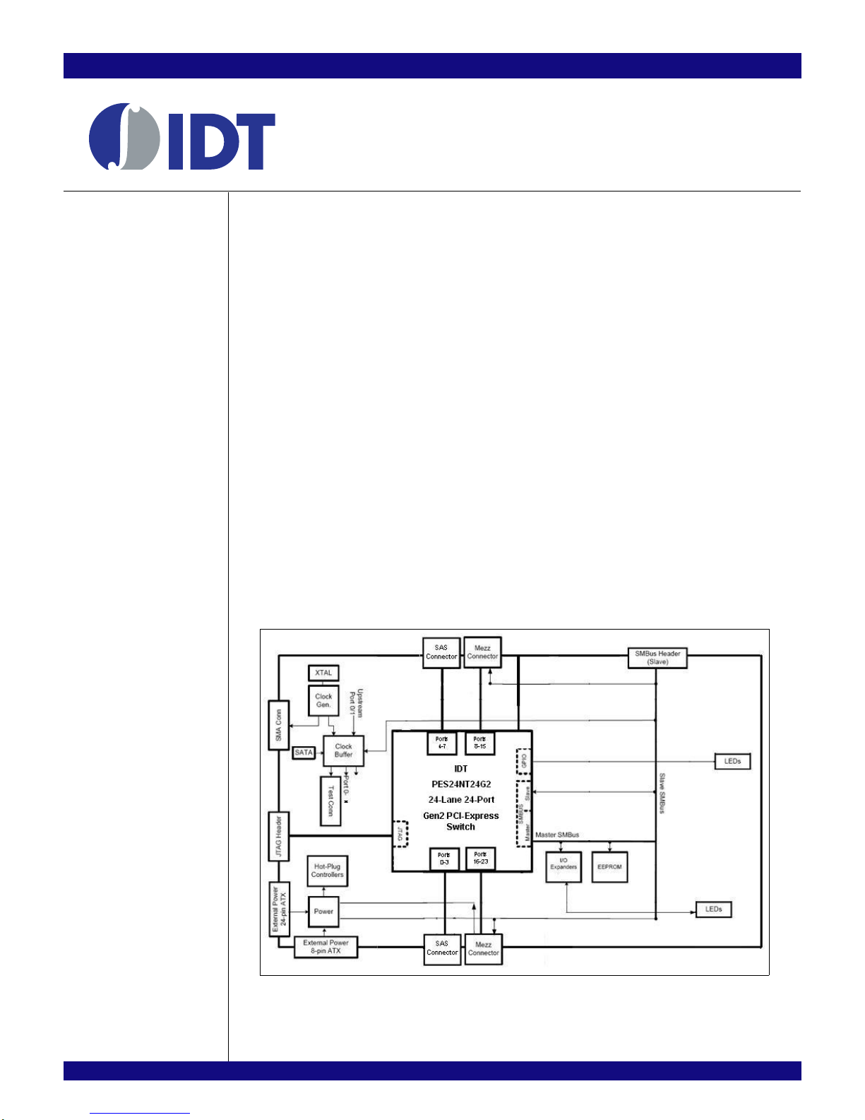
The EB-LOGAN-19 brings out all 24 lanes of the device to two Mezzanine connectors and two SAS
connectors (see
of daughter cards (provided by IDT) can then be plugged into the Mezzanine connectors to facilitate
connectivity to one x8 or two x4 or four x2 or eight x1 link partners. Link partners may be plugged directly
into these daughter cards or they can be connected to these daughter cards via SAS or SATA cables and a
different board with PCIe slots known as the 12-PACK board (provided by IDT). Given that majority of the
hosts / servers offer PCIe standard slots, IDT provides the necessary adapter cards that may be plugged
into these host / server slots as well as the cables that connect such adapters to the daughter cards which
in turn are plugged into the main evaluation board on which the IDT PCIe switch device is populated.
The EB-LOGAN-19 is also used by IDT to reproduce system-level hardware or software issues reported
by customers.
LOGAN-19 board.
Figure 1.1) located close to the device - one connector per stack of 4 lanes. Various types
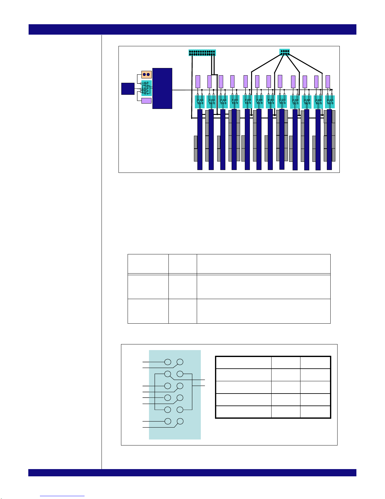
Figure 1.1 illustrates the functional block diagram representing the main parts of the EB-
89EB-LOGAN-19 Evaluation Board 1 - 1 February 16, 2011
Figure 1.1 Function Block Diagram of the EB-LOGAN-19 Evaluation Board
Page 10

IDT Description of the EB-LOGAN-19 Evaluation Board
Notes
Board Features
Hardware
PES24NT24G2 PCIe 24-port switch
– Twenty four ports (each x1) - for port 8 and higher, adjacent ports may be combined to create x2,
x4 or x8 ports
– PCIe Base Specification Revision 2.1 compliant (Gen2 SerDes speeds of 5 GT/S)
– Up to 2048 byte maximum Payload Size
– Automatic lane reversal and polarity inversion supported on all lanes
– Automatic per port link width negotiation to x8, x4, x2, x1
– Power on reconfiguration via optional serial EEPROM connected to the SMBUS Master interface
Upstream, Downstream Ports
– The EB-LOGAN-19 has minimum of one port configured as upstream port to be plugged into a
host slot through an adaptor and a cable.
– Up to 23 ports can be configured as downstream ports, for PCIe endpoint add-on cards to be
plugged in. The slot connectors can be configured to be x1, x2, x4 or x8, but are mechanically
open-ended on one side to allow card widths greater than x8 (e.g. x16) to be populated.
– When used in multi-partition mode, the device can be programmed through the serial EEPROM
to generate the appropriate number of upstream and downstream ports per partition.
Numerous user selectable configurations set using onboard jumpers and DIP-switches
– Source of clock - host clock or onboard clock generator
– Two clock rates (100/125 MHz) from an onboard clock generator
– Flexible clocking modes
• Common clock
• Non-common clock
• Local port clocking on ports that support this feature
– Boot mode selection
SMBUS Slave Interface (4 pin header)
SMBUS Master Interface connected to the Serial EEPROMs through I/O expander
Push button for Warm Reset
Many LEDs to display status, reset, power, hotplug, etc.
JTAG connector to the PES24NT24G2 JTAG pins.
Software
There is no software or firmware executed on the board. However, useful software is provided along
with the Evaluation Board to facilitate configuration and evaluation of the PES24NT24G2 within host
systems running popular operating systems.
Installation programs
– Operating Systems Supported: WindowsServer200x, WindowsXP, Vista, Linux
GUI based application for Windows and Linux
– Allows users to view and modify registers in the PES24NT24G2
– Binary file generator for programming the serial EEPROMs attached to the SMBUS.
Other
SMBUS cable may be required for certain evaluation exercises.
SMA connectors are provided on the EB-LOGAN-19 board for clock outputs.
Revision History
April 13, 2010: Initial publication of evaluation board manual.
89EB-LOGAN-19 Evaluation Board 1 - 2 February 16, 2011
Page 11

IDT Description of the EB-LOGAN-19 Evaluation Board
Notes
April 23, 2010: Updated Schematics in Chapter 4.
February 16, 2011: Changed default settings from Off to On in Tables 2.3 and 2.4.
89EB-LOGAN-19 Evaluation Board 1 - 3 February 16, 2011
Page 12

IDT Description of the EB-LOGAN-19 Evaluation Board
Notes
89EB-LOGAN-19 Evaluation Board 1 - 4 February 16, 2011
Page 13
Chapter 2
Installation of the EB-LOGAN-19
Evaluation Board
®
Notes
EB-LOGAN-19 Installation
This chapter discusses the steps required to configure and install the EB-LOGAN-19 evaluation board.
All available DIP switches and jumper configurations are explained in detail.
The primary installation steps are:
1. Configure jumper/switch options suitable for the evaluation or application requirements.
2. Connect PCI Express endpoint cards to the downstream port PCIe slots on the evaluation board.
3. Make sure that the host system (motherboard with root complex chipset) is powered off.
4. Connect the evaluation board to the host system.
5. Apply power to the host system.
The EB-LOGAN-19 board is typically shipped with all jumpers and switches configured to their default
settings. In most cases, the board does not require further modification or setup however please visit IDT
website and fill out the Technical Support Request form at http://www.idt.com/?app=TechSupport for other
configurations.
PCI Express Mezzanine and Edge Adapters
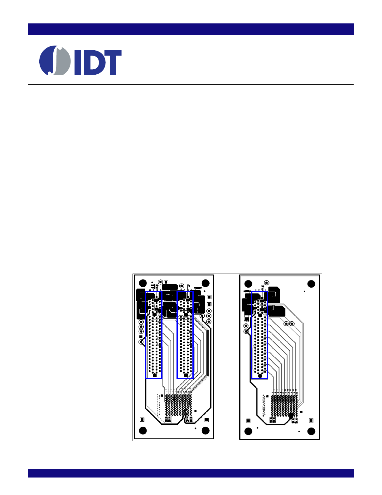
The PCI Express lanes are broken out to four Mezzanine connectors on EB-LOGAN-19 Evaluation
Board. The adapter cards are used to convert Mezzanine connector into PCI Express slot connector(s) or
Internal mini SAS (iSAS) connectors or both. A Bifurcated Mezzanine Card has two mechanical x8 PCIe
Slots (x4 electrically) while a Merged Mezzanine Card has single x8 PCIe Slot. Pictured in
Figure 2.1.
Figure 2.1 Bifurcated and Merged Mezzanine Cards
89EB-LOGAN-19 Evaluation Board 2 - 1 February 16, 2011
Page 14
IDT Installation of the EB-LOGAN-19 Evaluation Board
Notes
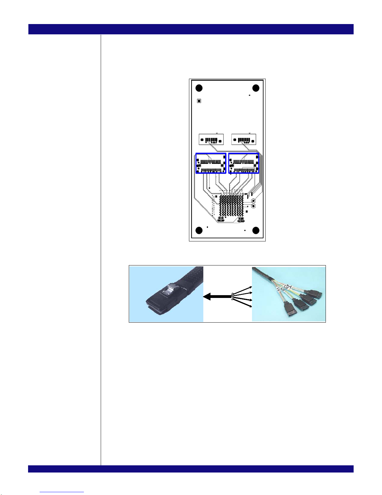
Pictured in Figure 2.2 is the mini-SAS Mezzanine card which consists of two iSAS and two SATA
connectors. Each iSAS connector supports up to PCI Express x4 width and the SATA connectors are used
for clock and reset signals of each x4 or less stack/port. An iSAS-to-SATA breakout cable shown in
Figure
2.3 is used connect from iSAS to edge adapter and/or 12PACK.
Figure 2.2 MiniSAS Mezzanine Adapter
SA S (x 4) – f our
SA S (x 4) – f our
SATA (x 1 )
SATA (x 1 )
breakout c ab le
breakout c ab le
Figure 2.3 EB-LOGAN-19 iSAS-to-SATA Breakout Cable
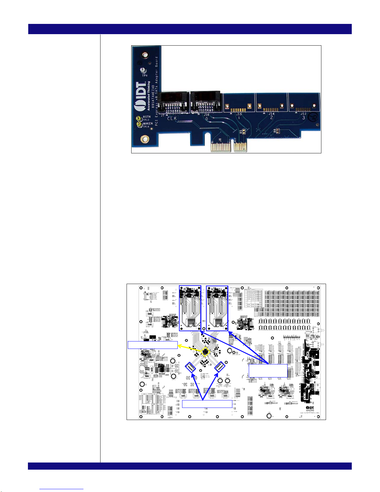
The PCI Express Edge to SATA Adapter, pictured in Figure 2.4, can be inserted into any physical PCIe
slot on a host system and in combination with mini-SAS Mezzanine Card, such as the one in Figure 2.2, to
form a link between evaluation main board and the host system. There are 5 SATA connectors which one
connector (J7) is for clock and reset, and the rest supports one PICe lane per SATA connector. The edge
adapters can be inserted into a mechanical x1 or greater slot.
89EB-LOGAN-19 Evaluation Board 2 - 2 February 16, 2011
Page 15
IDT Installation of the EB-LOGAN-19 Evaluation Board
Notes
Figure 2.4 PCIe x1 Edge-to-SATA Adapter
Hardware Description
The PES24NT24G2 is a 24-lane, 24-port PCI Express® switch. It is a peripheral chip that performs PCI
Express based switching with a feature set optimized for high performance applications such as servers
and storage. It provides fan-out and switching functions between a PCI Express upstream port and down
stream ports or peer-to-peer switching between downstream ports. Furthermore, up to eight ports can be
configured as NTB ports for multi-root application.
-
The EB-LOGAN-19 Main Board, shown in Figure 2.5, will support up to 4 PCI Express downstream
ports and up to 23 ports when using two 12PACK Daughter Boards.
Basic requirements for the board to run are:
– Host system with a PCI Express root complex supporting x1 configuration through a PCI Express
x1 slot.
– – x1, x2, x4, or x8 PCI Express Endpoint Cards.
DUT on bottom side
DUT on bottom side
Me zzto tw o x 4
Me zzto tw o x 4
slot connectors
slot connectors
x4 iSAS connectors
x4 iSAS connectors
89EB-LOGAN-19 Evaluation Board 2 - 3 February 16, 2011
Figure 2.5 EB-LOGAN-19 Evaluation Main Board
Page 16
IDT Installation of the EB-LOGAN-19 Evaluation Board
Notes
8-PIN EPS 12V
8-PIN EPS 12V
+12
+12
SATA
SATA
SATA
SATA
SATA
CL K
CL K
S
S
A
A
T
T
A
A
S
S
A
A
T
T
S
S
S
S
A
A
L
L
L
L
O
O
O
O
S
S
S
S
A
A
A
A
T
T
T
T
T
T
T
T
A
A
A
A
7
6
7
6
S
S
S
S
A
A
A
A
T
T
T
T
A
A
A
A
x4
x4
Data
Data
SATA
SATA
SATA
CLK
CLK
S
S
L
L
O
O
S
S
A
A
T
T
T
T
A
A
5
5
S
S
A
A
T
T
A
A
x2
x2
Data
Data
SATA
SATA
SATA
SATA
SATA
CLK
CLK
CLK
CLK
S
S
A
A
T
T
A
A
S
S
A
A
T
T
A
A
S
S
A
A
T
T
A
A
S
S
A
A
T
T
A
A
x8
x8
Dat a
Dat a
CLK
CLK
S
S
S
S
A
A
A
A
T
T
T
T
A
A
A
A
S
S
S
S
A
A
A
A
T
T
T
S
S
L
L
O
O
T
T
4
4
T
S
S
S
A
A
S
S
A
A
T
T
A
A
S
S
A
A
T
T
A
A
S
A
A
L
L
L
L
O
O
O
O
S
S
S
S
A
A
A
A
T
T
T
T
T
T
T
T
A
A
A
A
3
2
3
2
S
S
S
S
A
A
A
A
T
T
T
T
A
A
A
A
x2
x2
x4
x4
Dat a
Dat a
Data
Data
SATA
SATA
SATA
CLK
CLK
CLK
S
S
A
A
T
T
A
A
S
S
A
A
T
T
A
A
x2
x2
Data
Data
CLK
CLK
CLK
S
S
S
S
A
A
A
A
T
T
T
T
A
A
A
A
S
S
S
S
A
A
A
A
T
T
T
T
S
S
S
S
A
A
A
A
L
L
L
L
O
O
O
O
S
S
S
S
A
A
A
A
T
T
T
T
T
T
T
T
A
A
A
A
1
1
0
0
S
S
S
S
A
A
A
A
T
T
T
T
A
A
A
A
x8
x8
Data
Data
On-Board
On-Board
Clock Gen
Clock Gen
SMA
SMASMA
SATA
SATA
1:12
1:12
Buffe r
Buffe r
24-PIN ATX
24-PIN ATX
clk[0:11]
clk[0:11]
+3.3
+3.3
SATA
SATA
S
S
A
A
T
T
A
A
S
S
A
A
T
T
A
A
x2
x2
Data
Data
+12
+12
SATA
SATA
SATA
CLK
CLK
S
S
A
A
T
T
A
A
S
S
A
A
T
T
S
S
S
S
A
A
L
L
L
L
O
O
O
O
S
S
A
A
T
T
T
T
T
T
A
A
1
1
1
1
S
S
1
0
1
0
A
A
T
T
A
A
x4
x4
Data
Data
SATA
SATA
SATA
CLK
CL K
CL K
S
S
A
A
T
T
A
A
S
S
A
A
T
T
A
A
x2
x2
Data
Data
CLK
CLK
CLK
S
S
S
S
A
A
A
A
T
T
T
T
A
A
A
A
S
S
S
S
A
A
A
A
T
T
T
T
S
S
S
S
A
A
A
A
L
L
L
L
O
O
O
O
S
S
S
S
A
A
A
A
T
T
T
T
T
T
T
T
A
A
A
A
8
8
9
9
S
S
S
S
A
A
A
A
T
T
T
T
A
A
A
A
x8
x2
x8
x2
Data
Data
Data
Data
Figure 2.6 12PACK PCIe Slots Breakout Daughter Board
Reference Clocks
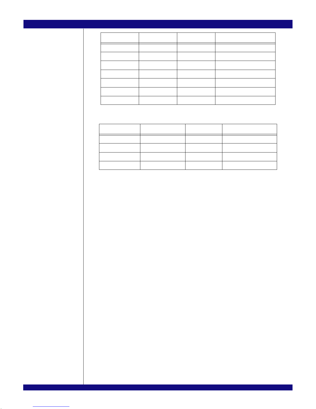
Global Reference Input Clocks
The PES24NT24G2 requires two differential reference clocks. The EB-LOGAN-19 derives these clocks
from SMA connectors (J17, J20, J66, J67), clock buffer (U50), or SATA connectors (J21, J22) as described
in
Table 2.1 and Figures 2.7 and 2.8.
IOA
IOA
IOB
IOB
IOC
IOC
IOD
IOD
Global
Clock#
Jumper Selection
0 J18 [1-3 / 2-4] SMA (J66/J67)
[5-7 /6-8] From Clock Buffer U51 (default)
[7-9 / 8-10] SATA, J21
1 J19 [1-3 / 2-4] SMA (J17/J20)
[5-7 /6-8] From Clock Buffer U51 (default)
[7-9 / 8-10] SATA, J22
Table 2.1 EB-LOGAN-19 Global Clock Select
1
1
3
3
5
5
7
7
9
9
11
11
2
2
4
4
6
6
8
8
10
10
12
12
JMP2JMP1CONNECTION
JMP2JMP1CONNECTION
2-41-3IOA <-> COM
2-41-3IOA <-> COM
4-63-5IOB <-> COM
4-63-5IOB <-> COM
8-107-9IOC <-> COM
8-107-9IOC <-> COM
10-129-11IOD <-> COM
10-129-11IOD <-> COM
89EB-LOGAN-19 Evaluation Board 2 - 4 February 16, 2011
Figure 2.7 Differential Jumper Arrangement
Page 17
IDT Installation of the EB-LOGAN-19 Evaluation Board
Notes
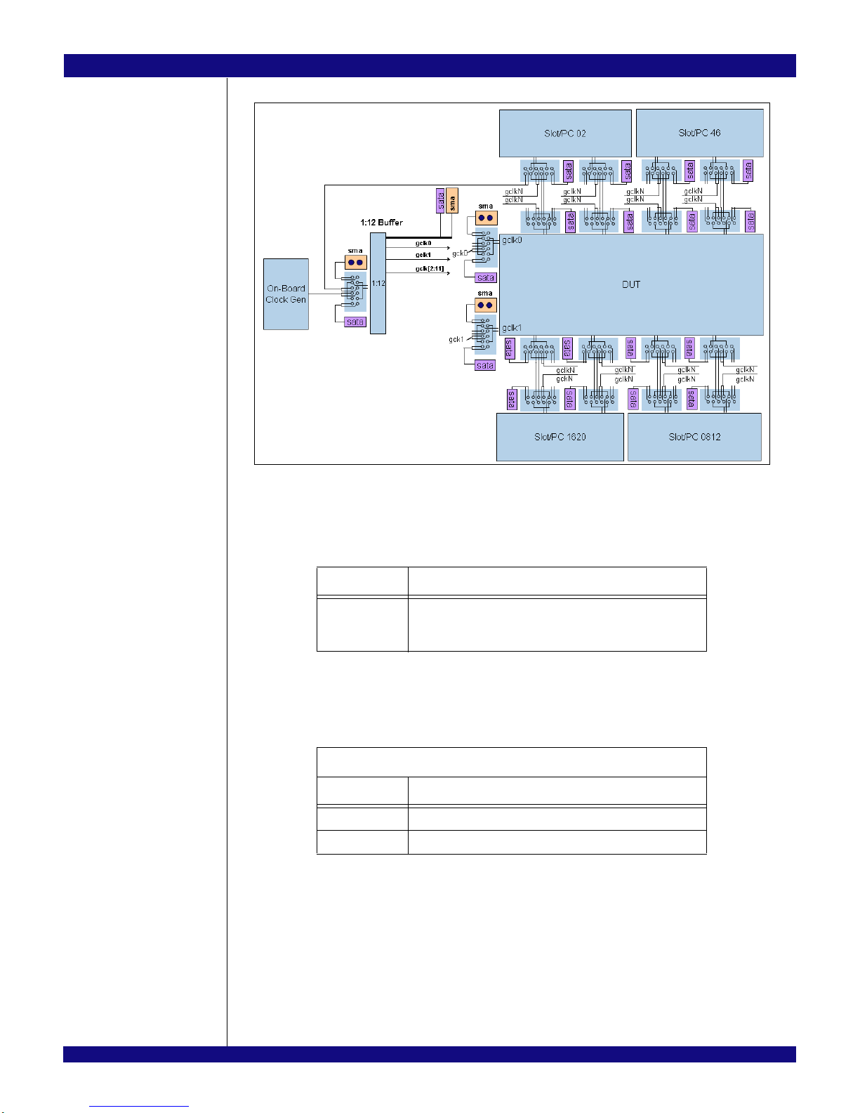
Figure 2.8 Reference Clock Configuration
By default the clock buffer derives its clock from a common source. The common source can be the host
system’s reference clock, the onboard clock generator, or SATA connector (J8). See
Table 2.2.
.
Jumper Selection
J6 [1-3 / 2-4] SMA (J5/J7)
[5-7 / 6-8] Onboard Clock Generator (U49)
[7-9 / 8-10] SATA (J8) (default)
Table 2.2 Clock Buffer Input Sources
The frequency of the global reference clock input may be selected by the Clock Frequency Select
(GCLKFEL) pin to be either 100 MHz or 125 MHz as described in
Global Clock Frequency Switch - SW10[2
SW10[2] Clock Frequency
ON 100 MHz (Default)
OFF 125 MHz
Table 2.3 Global Reference Input Clock Frequency Select
Table 2.3.
The source for the onboard clock is the ICS841484 clock generator device (U49) connected to a 25MHz
oscillator (X1). When using the onboard clock generator, the output frequency is fixed at 100MHz. There
fore, ICS_FS (S10, bit 1) is ON as the default setting. See Table 2.4.
89EB-LOGAN-19 Evaluation Board 2 - 5 February 16, 2011
-
Page 18
IDT Installation of the EB-LOGAN-19 Evaluation Board
Notes
Onboard Clock Frequency Switch - S10[1]
S10[1] Clock Frequency
ON 100 MHz (Default)
OFF 125 MHz
Table 2.4 Onboard Clock Generator Frequency Select
The output of the onboard clock generator is accessible through two yellow colored loop connectors
located on the Evaluation Board. See
capturing purposes and cannot be used to drive the clock from an external source.
Onboard Reference Clock Output (Differential)
J119 Positive Reference Clock
J120 Negative Reference Clock
J121 SATA Reference Clock
Table 2.5 Onboard Reference Clock Generator Access Points
Table 2.5. This can be used to connect a scope for probing or
Local Port Input Clocks
Associated with some ports is a port reference clock input (PxCLK). Depending on the port clocking
mode, a differential reference clock is driven into the device on the corresponding PxCLKP and PxCLKN
pins. The frequency of a port reference clock input is always 100 MHz.
Table 2.6 lists the possible sources
for the port reference clock input, and Table 2.7 lists the possible sources for the slot clock input.
Port # Header Selection
8 J13 [1-3 / 2-4] Onboard Clock Generator (U118)
[5-7 / 6-8] Slot Clock Header (J31)
[7-9 / 8-10] SATA (J62) (default)
16 J15 [1-3 / 2-4] Onboard Clock Generator (U120)
[5-7 / 6-8] Slot Clock Header (J33)
[7-9 / 8-10] SATA (J64) (default)
Table 2.6 EB24NT24G2 Port Clock Select
Slot/Port # Header Selection
8 J31 [1-3 / 2-4] Onboard Clock Generator (U118)
[3-5 / 4-6] From Clock Buffer (default)
[7-9 / 8-10] To P08CLK Clock Header (J13)
[9-11 / 8-10] SATA (J35)
89EB-LOGAN-19 Evaluation Board 2 - 6 February 16, 2011
Table 2.7 EB-LOGAN-19 Slot Clock Select (Part 1 of 2)
Page 19
IDT Installation of the EB-LOGAN-19 Evaluation Board
Notes
Slot/Port # Header Selection
12 J32 [1-3 / 2-4] From Clock Buffer (default)
[3-5 / 4-6] SATA (J36)
16 J33 [1-3 / 2-4] Onboard Clock Generator (U120)
[3-5 / 4-6] From Clock Buffer (default)
[7-9 / 8-10] To P16CLK Clock Header (J15)
[9-11 / 8-10] SATA (J37)
20 J34 [1-3 / 2-4] From Clock Buffer (default)
[3-5 / 4-6] SATA (J38)
Table 2.7 EB-LOGAN-19 Slot Clock Select (Part 2 of 2)
CLKMODE Selection
All ports in the PES24NT24G2 device (upstream and downstream) use global clocked mode. The port
clocking mode of a port is determined by the state of the CLKMODE[1:0] pins in the boot configuration
vector as shown in
Table 2.8. This field determines the initial value of the Slot Clock Configuration (SCLK)
field in each port’s PCI Express Link Status (PCIELSTS) register. The SCLK field controls the advertisement of whether or not the port uses the same reference clock source as the link partner. A one in the SCLK
field indicates that the port and its link partner use the same reference clock source. This is defined as
Common Clock Configuration by the PCI Express Base Specification. A zero in the SCLK field indicates
that the port and its link partner do not use the same reference clock source.
SW10[8]
CLKMODE[0]
SW10[7]
CLKMODE[1]
Port 0
SCLK
Port[23:1]
SCLK
ON ON 0 0
OFF ON 1 0
ON OFF 0 1
OFF OFF 1 1
Table 2.8 CLKMODE Selection PES24NT24G2
Power Sources
Power for the PES24NT24G2 and all downstream ports will be generated from the 12V from an external
power connector. See
Table 2.9. A 12V to 3.3V DC-DC converter will be used to provide power to five
switching regulators to generate VDDCORE, VDDPEA, VDDPETA, VDDPEHA, and VDDIO voltages. The
3.3V from the DC-DC converter will be used to power the clock buffers and circuitries.
The external power supply connectors are 24-pin (J69) and 8-pin (J68) molex connector as described in
Tables
2.9 and 2.10. The +12V3 is used to power PES32NT24AG2 and downstream slots 16 and 20. The
+12V2 is used to power downstream slots 8 and 12.
Pin Signal Pin Signal
1 +3.3V 13 +3.3V
2 +3.3V 14 -12V
3 GND 15 GND
4 +5V 16 PS_ON
5 GND 17 GND
89EB-LOGAN-19 Evaluation Board 2 - 7 February 16, 2011
Table 2.9 EPS12V 24-pin Power Connector - J6 (Part 1 of 2)
Page 20
IDT Installation of the EB-LOGAN-19 Evaluation Board
Notes
Pin Signal Pin Signal
6 +5V 18 GND
7 GND 19 GND
8 PWR_OK 20 NC
9 5VSB 21 +5V
10 +12V3 22 +5V
11 +12V3 23 +5V
12 +3.3V 24 GND
Table 2.9 EPS12V 24-pin Power Connector - J6 (Part 2 of 2)
Pin Signal Pin Signal
1 GND 5 +12V1
2 GND 6 +12V1
3 GND 7 +12V2
4 GND 8 +12V2
Table 2.10 EPS12V 8-Pin Connector - J5
The power on switch located at S1 can be used to control the supply power from the external power
supply connector. Add a shunt to W27 to enable power on switch.
PCI Express Analog Power Voltage Regulator
A voltage regulator (U65) provides a 2.5V PCI Express analog power voltage (shown as VDDPEHA) to
the PES24NT24G2.
PCI Express Digital Power Voltage Converter
A separate voltage regulator (U62) provides a 1.0V PCI Express analog power voltage (shown as
VDDPEA) to the PES24NT24G2.
PCI Express Transmitter Analog Voltage Converter
A separate voltage regulator (U68) provides a 1.0V PCI Express transmitter analog voltage (shown as
VDDPETA) to the PES24NT24G2.
Core Logic Voltage Converter
A separate voltage regulator (U59) provides the 1.0V core voltage (VDDCORE) to the PES24NT24G2.
3.3V I/O Voltage Regulator
A separate voltage regulator (U56) provides the 3.3V I/O voltage (VDDIO) to the PES24NT24G2.
Power-up Sequence f or PES24NT24G2
During power supply ramp-up, VDDCORE must remain at least 1.0V below VDDIO at all times. There
are no other power-up sequence requirements for the various operating supply voltages.
Heatsink Requirement
The EB-LOGAN-19 evaluation board utilizes a heatsink with integrated fan.
89EB-LOGAN-19 Evaluation Board 2 - 8 February 16, 2011
Page 21

IDT Installation of the EB-LOGAN-19 Evaluation Board
Notes
Reset
The PES24NT24G2 supports two types of reset mechanisms as described in the PCI Express specifica-
tion:
– Fundamental Reset: This is a system-generated reset that propagates along the PCI Express
tree through a single side-band signal PERST# which is connected to the Root Complex, the
PES24NT24G2, and the endpoints.
– Hot Reset: This is an In-band Reset, communicated downstream via a link from one device to
another. Hot Reset may be initiated by software. This is further discussed in the PES24NT24G2
User Manual. The EB-LOGAN-19 evaluation board provides seamless support for Hot Reset.
Fundamental Reset
There are two types of Fundamental Resets which may occur on the EB-LOGAN-19 evaluation board:
– Cold Reset: During initial power-on, the onboard voltage monitor (TLC7733D) will assert the PCI
Express Reset (PERSTN) input pin of the PES24NT24G2.
– Warm Reset: This is triggered by hardware while the device is powered on. Warm Reset can be
initiated by two methods:
• Pressing a push-button switch (S3) located on EB-LOGAN-19 board
• The host system board IO Controller Hub asserting PERST# signal, which propagates through
the PCIe upstream edge connector of the EB-LOGAN-19.
Both events cause the onboard voltage monitor (TLC7733D) to assert the PCI Express Reset
(PERSTN) input of the PES24NT24G2 while power is on.
Downstream Reset
Single Partition Mode without Hot Plug:
When the evaluation board initially powers on is assumes the following:
The switch is configured in single partition mode.
Slot 0 is the root port and controls the downstream port resets.
Ports 1-23 are downstream ports.
Hot Plug is disabled.
The following behavior should be observed:
The resets to slots 1-23 should initially be asserted and remain this way until after the fundamental
reset is initially de-asserted.
The assertion of slot 0 reset should propagate to slots 1-23.
Stack Configuration
The PES24NT24G2 contains four stack blocks labeled Stack 0, Stack 1, Stack 2, and Stack 3. Stacks 0
and 1 have four x1 ports each, and stacks 2 and 3 have eight x1 ports each. This provides a total of 24
ports in the device labeled port 0 through port 23.
Table 2.11 lists the ports associated with each stack.
Stacks 0 and 1 have non-mergeable x1 ports. Stacks 2 and 3 may be configured as eight x1 ports, four
x2 ports, two x4 ports, one x8 port, and any combinations in between. The configuration of each stack is
controlled by the Stack Configuration (STK[3:2]CFG) registers. For possible configurations please refer to
the device user manual.
89EB-LOGAN-19 Evaluation Board 2 - 9 February 16, 2011
Page 22
IDT Installation of the EB-LOGAN-19 Evaluation Board
Notes
Stack
Stack 0 0, 1, 2, 3
Stack 1 4, 5, 6, 7
Stack 2 8, 9, 10, 11, 12, 13, 14, 15
Stack 3 16, 17, 18, 19, 20, 21, 22, 23
Ports Associated with the
Stack
Table 2.11 Ports in Each Stack
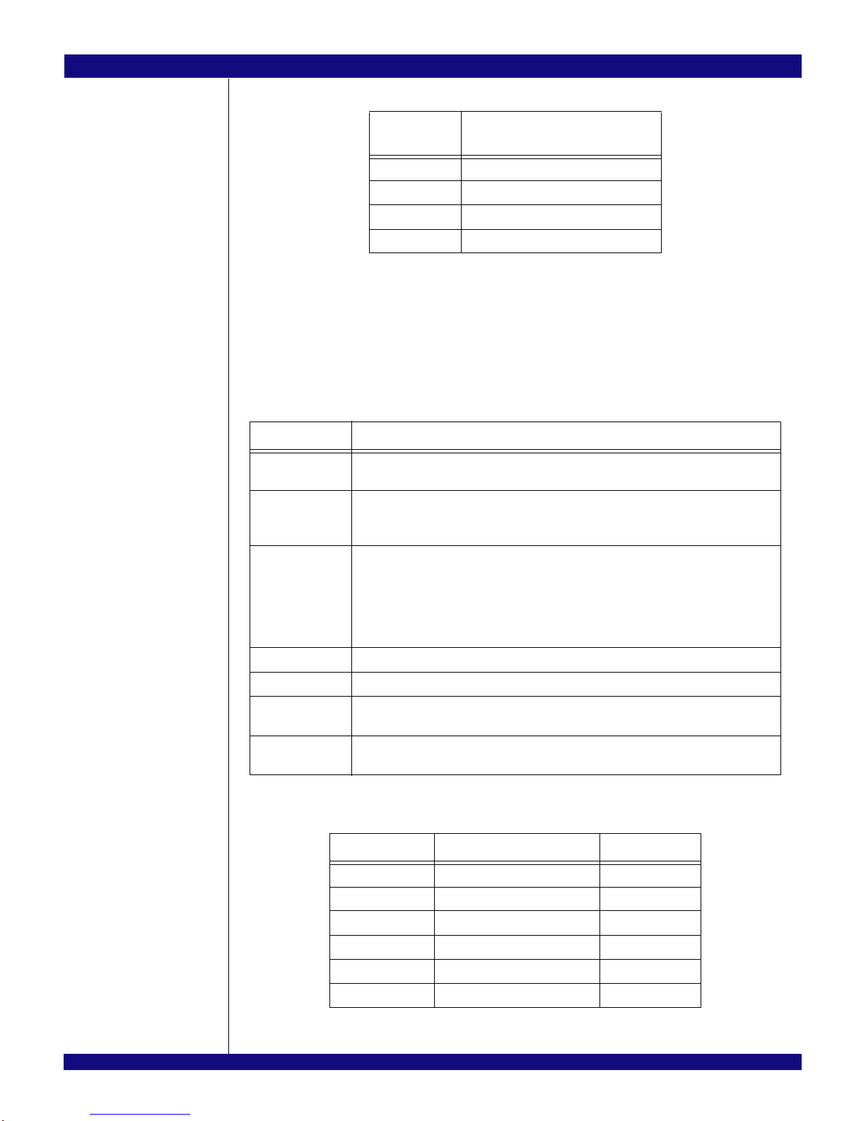
Boot Configuration Vector
A boot configuration vector consisting of the signals listed in Table 2.12 is sampled by the
PES24NT24G2 during a fundamental reset (while PERSTN is active). The boot configuration vector defines
the essential parameters for switch operation and is set using DIP switches S5, SW8, SW9 and SW10 as
defined in
Table 2.13.
Signal Description
GCLKFSEL Global Clock Frequency Select. This pin specifies the frequency of the GCLKP and
GCLKN signals.. Default: low
CLKMODE[1:0] Clock Mode. These pins specify the clocking mode used by switch ports. See Table 2.8 for
a definition of the encoding of these signals. The value of these signals may be overridden
by modifying the Port Clocking Mode (PCLKMODE) register.. Default: 0x3
RSTHALT Reset Halt. When this pin is asserted during a switch fundamental reset
sequence, the switch remains in a quasi-reset state with the Master and Slave SMBuses
active. This allows software to read and write registers internal to the device before normal
device operation begins. The device exits the quasi-reset state when the RSTHALT
bit is cleared in the SWCTL register by an SMBus master. Refer to section Switch Fundamental Reset on page 3-2 for further details. Default: low
SSMBADDR[2:1] Slave SMBus Address. SMBus address of the switch on the slave SMBus. Default: 0x3
SWMODE[3:0] Switch Mode. These pins specify the switch operating mode. Default: 0x0
STK2CFG[4:0] Stack 2 Configuration. These pins select the configuration of stack 2 during a switch fun-
STK3CFG[4:0] Stack 3 Configuration. These pins select the configuration of stack 3 during a switch fun-
89EB-LOGAN-19 Evaluation Board 2 - 10 February 16, 2011
damental reset. Default: 0x1
damental reset. Default: 0x1
Table 2.12 Boot Configuration Vector Signals
Location Signal Default
S5[1] SWMODE[0] ON
S5[2] SWMODE[1] ON
S5[3] SWMODE[2] ON
S5[4] SWMODE[3] ON
SW8[1] STK2CFG[0] OFF
SW8[2] STK2CFG[1] ON
Table 2.13 Boot Configuration Vector Switches S5, SW8 - SW10 (Part 1 of 2)
Page 23

IDT Installation of the EB-LOGAN-19 Evaluation Board
Notes
Location Signal Default
SW8[3] STK2CFG[2] ON
SW8[4] STK2CFG[3] ON
SW8[5] STK2CFG[4] ON
SW9[1] STK3CFG[0] OFF
SW9[2] STK3CFG[1] ON
SW9[3] STK3CFG[2] ON
SW9[4] STK3CFG[3] ON
SW9[5] STK3CFG[4] ON
SW10[2] GCLKFSEL ON
SW10[4] RSTHALT ON
SW10[5] SSMBADDR[2] OFF
SW10[6] SSMBADDR[1] OFF
SW10[7] CLKMODE[1] OFF
SW10[8] CLKMODE[0] OFF
Table 2.13 Boot Configuration Vector Switches S5, SW8 - SW10 (Part 2 of 2)
SMBus Interfaces
The System Management Bus (SMBus) is a two-wire interface through which various system compo-
nent chips can communicate. It is based on the principles of operation of I2C. Implementation of the SMBus
signals in the PCI Express connector is optional and may not be present on the host system. The SMBus
interface consists of an SMBus clock pin and an SMBus data pin.
The PES24NT24G2 contains two SMBus interfaces: a slave SMBus interface and a master SMBus
interface. The slave SMBus interface allows a SMBus Master device full access to all software-visible regis
ters. The Master SMBus interface provides a connection to the external serial EEPROM used for initialization and the I/O expanders used for hot-plug signals.
SMBus Slave Interface
On the PES24NT24G2 board, the slave SMBus interface is accessible through a 4-pin header as
described in
Table 2.14.
.
Slave SMBus Interface Connector J71
Pin Signal
1 SDA
2 GND
3 SCL
4 NC
-
For a fixed address, the SMBus address of the PES24NT24G2 slave interface is 0b1110111 by default
and is configurable using DIP Switches SW10[5] and SW10[6] as described in
89EB-LOGAN-19 Evaluation Board 2 - 11 February 16, 2011
Table 2.14 Slave SMBus Interface Connector
Table 2.15.
Page 24

IDT Installation of the EB-LOGAN-19 Evaluation Board
Notes
Slave Interface Address Configuration
Address Bit Signal
1 SSMBUSADDR[1]
2 SSMBUSADDR[2]
3 1
4 0
5 1
6 1
7 1
Table 2.15 SMBus Slave Interface Address Configuration
The slave SMBus interface responds to the following SMBus transactions initiated by an SMBus master.
Initiation of any SMBus transaction other than those listed above produces undefined results. See the
SMBus 2.0 specification for a detailed description of the following transactions:
– Byte and Word Write/Read
– Block Write/Read
SMBus Master Interface
Connected to the master SMBus interface are twenty-two 16-bit I/O Expanders (MAX7311AUG) and a
serial EEPROM, U77 (24LC512). The I/O Expanders are used as the interface for the onboard hot-plug
controllers (MIC2591B). The lower three bits of the bus address for the I/O Expander 0 through I/O
Expander 20 are fixed through the stuffing resistor as 0x20, 0x22, 0x24, 0x26, 0x28, 0x2A, 0x2C, 0x2E,
0x50, 0x52, x54, 0x56, 0x58, 0x5A, 0x5C, 0x5E, 0xB0, 0xA2, 0xA4, 0xA6, 0xA8, and 0xAA, respectively.
Note: Hot-plug is not implemented when the PES24NT24G2 is installed.
The seven bits address for the selected EEPROM device is fixed at 0b1010_000 by default.
JTAG Header
The EB-LOGAN-19 provides a JTAG connector J73 for access to the PES24NT24G2 JTAG interface.
The connector is a 2.54 x 2.54 mm pitch male 14-pin connector . Refer to
J73 pin out.
JTAG Connector J73
Pin Signal Direction Pin Signal Direction
1 /TRST - Test reset Input 2 GND —
3 TDI - Test data Input 4 GND —
5 TDO - Test data Output 6 GND —
7 TMS - Test mode select Input 8 GND —
9 TCK - Test clock Input 10 GND —
11 3.3V 12 N/C —
13 GND — 14 3.3V
T able 2.16 for the JTAG Connector
89EB-LOGAN-19 Evaluation Board 2 - 12 February 16, 2011
Table 2.16 JTAG Connector Pin Out
Page 25

IDT Installation of the EB-LOGAN-19 Evaluation Board
Notes
PCI Express Connectors
Pin Side A Side B
1 +12V 12V power PRSNT1# Hot-Plug presence detect
2 +12V 12V power +12V 12V power
3 RSVD Reserved +12V 12V power
4 GND Ground GND Ground
5 SMCLK SMBus clock JTAG2 TCK (Test Clock) JTAG i/f clk i/p
6 SMDAT SMBus Data JTAG TDI (Test Data Input)
7 GND Ground JTAG TDO (Test Data Output)
8 +3.3V 3.3V power JTAG TMS (Test Mode Select)
9 JTAG1 TRST# (Test/Reset) resets
JTAG i/f
10 3.3Vaux 3.3V auxiliary power +3.3V 3.3V power
11 WAKE# Signal for Link reactivation PERST# Fundamental Reset
Mechanical Key
12 RSVD Reserved GND Ground
13 GND Ground REFCLK+ REFCLK Reference clock
14 PETp0 Transmitter differential REFCLK- (differential pair)
15 PETn0 pair, Lane 0 GND Ground
+3.3V 3.3V power
16 GND Ground PERp0 Receiver differential
17 PRSNT2# Hot-Plug presence detect PERn0 pair, Lane 0
18 GND Ground GND Ground
19 PETp1 Transmitter differential RSVD Reserved
20 PETn1 pair, Lane 1 GND Ground
21 GND Ground PERp1 Receiver differential
22 GND Ground PERn1 pair, Lane 1
23 PETp2 Transmitter differential GND Ground
24 PETn2 pair, Lane 2 GND Ground
25 GND Ground PERp2 Receiver differential
26 GND Ground PERn2 pair, Lane 2
27 PETp3 Transmitter differential GND Ground
28 PETn3 pair, Lane 3 GND Ground
29 GND Ground PERp3 Receiver differential
30 RSVD Reserved PERn3 pair, Lane 3
31 PRSNT2# Hot-Plug presence detect GND Ground
32 GND Ground RSVD Reserved
33 PETp4 Transmitter differential RSVD Reserved
89EB-LOGAN-19 Evaluation Board 2 - 13 February 16, 2011
Table 2.17 PCI Express x8 Connector Pinout (Part 1 of 2)
Page 26

IDT Installation of the EB-LOGAN-19 Evaluation Board
Notes
Pin Side A Side B
34 PETn4 pair, Lane 4 GND Ground
35 GND Ground PERp4 Receiver differential
36 GND Ground PERn4 pair, Lane 4
37 PETp5 Transmitter differential GND Ground
38 PETn5 pair, Lane 5 GND Ground
39 GND Ground PERp5 Receiver differential
40 GND Ground PERn5 pair, Lane 5
41 PETp6 Transmitter differential GND Ground
42 PETn6 pair, Lane 6 GND Ground
43 GND Ground PERp6 Receiver differential
44 GND Ground PERn6 pair, Lane 6
45 PETp7 Transmitter differential GND Ground
46 PETn7 pair, Lane 7 GND Ground
47 GND Ground PERp7 Receiver differential
48 PRSNT2# Hot-Plug presence detect PERn7 pair, Lane 7
49 GND Ground GND Ground
Table 2.17 PCI Express x8 Connector Pinout (Part 2 of 2)
89EB-LOGAN-19 Evaluation Board 2 - 14 February 16, 2011
Page 27

IDT Installation of the EB-LOGAN-19 Evaluation Board
Notes
EB-LOGAN-19 Board Figure
Figure 2.9 EB24NT24G2 Evaluation Board
89EB-LOGAN-19 Evaluation Board 2 - 15 February 16, 2011
Page 28

IDT Installation of the EB-LOGAN-19 Evaluation Board
Notes
89EB-LOGAN-19 Evaluation Board 2 - 16 February 16, 2011
Page 29

Chapter 3
Software for the EB-LOGAN-19
Eval Board
®
Notes
Introduction
This chapter discusses some of the main features of the available software to give users a better understanding of what can be achieved with the EB-LOGAN-19 evaluation board using the device management
software.
Device management software and related user documentation are available on a CD which is included
in the Evaluation Board Kit. This information is also available on IDT FTP site and also at my.idt.com. For
more information, please go to:
email IDT at ssdhelp@idt.com.
http://www.idt.com/?app=TechSupport&prodFamily=PCIe%20Switches or
Device Management Software
The primary use of the Device Management Software package is to enable users of the evaluation
board to access all the registers in the PES24NT24G2 device. This access can be achieved using the PCI
Express in-band configuration cycles through the upstream port on the PES24NT24G2 or through the
SMBUS salve interface available on the IDT PCIe switch.
This software also enables users to save a snapshot of the current register set into a dump file which
can be used for debugging purposes. An export/import facility is also available to create and use “Configu
ration” files which can be used to initialize the switch device with specific values in specific registers.
A conversion utility is also provided to translate a configuration file into an EEPROM programmable data
structure. This enables the user to program an appropriate serial EEPROM with desirable register settings
for the PES24NT24G2, and then to populate that EEPROM onto the Evaluation Board. It is also possible to
program the EEPROM directly on the Evaluation Board using a feature provided by the software package.
The front-end of the Device Management Software is a user-friendly Graphical User Interface which
allows the user to quickly read or write the registers of interest. The GUI also permits the user to run the
software in “simulation” mode with no real hardware attached, allowing the creation of configuration files for
the PES24NT24G2 in the absence of the actual device.
-
Much of the Device Management Software is written with device-independent and OS-independent
code. The software is expected to work on Linux (/sys interface) and MS Windows XP. It may function well
on various flavors of MS Windows, but may not be validated on all. The fact that the software is device-inde
pendent assures its scalability to future PCIe parts from IDT. Once users are familiar with the GUI, they will
be able to use the same GUI on all PCIe parts from IDT. This software is customized for each device
through an XML device description file which includes information on the number of ports, registers, types
of registers, information on bit-fields within each register, etc.
The actual program name of the Device Management Software is “PCIeBrowser” (an executable file
under Windows or Linux). Revision 5.0.1 or later is required for devices in the PES24NT24G2 product
family family.
Device Drivers
The PES24NT24G2 and other members of this switch family offer Non-Transparent Bridging and built-in
DMA capability inside the device. Device drivers are needed to take advantage of these features. Sample
code for these drivers is available from IDT for the Linux operating system. Additionally, there a few other
software packages available from IDT. These packages are not related to the evaluation board per se, and
therefore not listed here. However, several of these packages may prove to be useful for specific device or
system functionality. For more information, please go to
Family=PCIe%20Switches or email IDT at ssdhelp@idt.com.
89EB-LOGAN-19 Evaluation Board 3 - 1 February 16, 2011
http://www.idt.com/?app=TechSupport&prod-
-
Page 30

IDT Software for the EB-LOGAN-19 Eval Board
Notes
89EB-LOGAN-19 Evaluation Board 3 - 2 February 16, 2011
Page 31

Chapter 4
Schematics
®
Notes
Schematics
89EB-LOGAN-19 Evaluation Board 4 - 1 February 16, 2011
Page 32

TITLE PAGE / TABLE OF CONTENTS
1.
MEZZANINE CONNECTOR PORTS 16, 20
24NT24AG2 - CLK, CONFIG, GPIO
PORT 8 CLOCK GENERATOR
PORT 16 CLOCK GENERATOR
POWER REGULATOR - VDDIO
POWER REGULATOR - VDDCORE
POWER REGULATOR - VDDPEA
POWER REGULATOR - VDDPEHA
POWER REGULATOR - VDDPETA
MIN LOAD RESISTORS
LED - PORT STATUS (6 OF 7)
LED - PORT STATUS (5 OF 7)
LED - PORT STATUS (4 OF 7)
LED - PORT STATUS (3 OF 7)
LED - PORT STATUS (2 OF 7)
LED - PORT STATUS (1 OF 7)
DIP SWITCHES
RESET, SMBUS, EEPROM, JTAG
22.
23.
24.
25.
26.
27.
31.
32.
28.
29.
30.
33.
34.
36.
35.
SLOT RESET SELECT HEADERS
PARTITION RESET SELECT HEADERS
12PK RIBBON CONNECTORS
41.
40.
39.
38
37.
CLOCK SELECTOR - DUT PCLK 0-20, GCLK 1-2
SLOT RESETS AND WAKE PULL-UPS
HOT PLUG CONTROL PORTS 16-20
HOT PLUG CONTROL PORTS 8-12
24NT24AG2 - SERDES
24NT24AG2 - POWER, GND
IOEXPANDER 0-3
IOEXPANDER 4-7
IOEXPANDER 8-11
IOEXPANDER 12-13
IOEXPANDER 16-19
IOEXPANDER 20-21
3.
16.
15.
14.
13.
12.
11.
10.
9.
7.
4.
6.
8.
POWER CONNECTORS
CLOCK SELECTOR - SLOTS 0-20
CLOCK BUFFER - 1
CLOCK
21.
20.
19.
18.
17.
SAS CONNECTOR PORTS 0-7
2.
5.
MEZZANINE CONNECTOR PORTS 8, 12
LED - PORT STATUS (7 OF 7)
Tue Apr 20 12:37:19 2010
SHEET 1 OF 41
EB-LOGAN-19
Tony Tran
2010
SCH-PESEB-002
Derek Huang
1.1
18-692-000
B
1.0 INITIAL RELEASE 2009-12-05 T. TRAN
6
A
TITLE
CHECKED BY
DCN
DESCRIPTION
DATE
REV
8
8
65 4
4
2
2
D
D
CC
BB
A
1
1
REV.
SIZE
3
COPYRIGHT (C) IDT
AUTHOR
DRAWING NO.
REVISIONS
CHANGE BY
3
7
FAB P/N
57
6024 SILVER CREEK VALLEY RD. SAN JOSE, CA 95138
CONFIDENTIAL PROPERTY OF INTEGRATED DEVICE TECHNOLOGY, INC.
Page 33

Tue Apr 20 12:38:25 2010
SHEET 2 OF 41
1.1
18-692-000
Derek Huang
2010
Tony Tran
SCH-PESEB-002
EB-LOGAN-19
B
C81
C80
C76
C73
C71
C68
C67
C63
B16
B17
B13
B14
B5
B6
B2
B3
A8
B11A11
A10
A9
B10
B9
B8
A16
A17
A13
A14
A5
A6
A2
A3
MTG9
MTG8
MTG7
MTG6
MTG5
MTG4
MTG3
MTG2
MTG1
B7
B4
B1
A18
A15
A12
A7
A4
B18
B15
B12
A1
J40
B16
B17
B13
B14
B5
B6
B2
B3
A8
B11A11
A10
A9
B10
B9
B8
A16
A17
A13
A14
A5
A6
A2
A3
MTG9
MTG8
MTG7
MTG6
MTG5
MTG4
MTG3
MTG2
MTG1
B7
B4
B1
A18
A15
A12
A7
A4
B18
B15
B12
A1
J39
C32
C28
C36
C38
C56
C50
C58
C59
5
5
5
5
5
5
5
55
5
5
5
5
5
5
5
5
5
5
5
5
5
5
5
5
5
5
5
5
5
5
5
SAS CONNECTOR PORTS 0-7
0.1UF
PE07TN0
0.1UF
PE07TP0
0.1UF
PE06TN0
0.1UF
PE06TP0
0.1UF
PE05TN0
0.1UF
PE05TP0
0.1UF
PE04TN0
0.1UF
PE04TP0
0.1UF
PE00TP0
0.1UF
PE00TN0
0.1UF
PE01TP0
0.1UF
PE01TN0
0.1UF
PE02TP0
0.1UF
PE02TN0
0.1UF
PE03TP0
0.1UF
PE03TN0
VERT
PE00RP0
PE00RN0
PE01RP0
PE03RN0
PE03RP0
PE02RN0
PE02RP0
PE01RN0
SMT
PE07RN0
PE07RP0
PE06RN0
PE06RP0
PE05RN0
PE05RP0
PE04RN0
PE04RP0
SMT
VERT
IDT
TITLE
DRAWING NO.
AUTHOR
CHECKED BY
COPYRIGHT (C)
3
SIZE
REV.
FAB P/N
1
1
A A
B B
C C
D
D
2
2
4
45
6
67
7
8
38 5
6024 SILVER CREEK VALLEY ROAD. SAN JOSE, CA 95138
CONFIDENTIAL PROPERTY OF INTEGRATED DEVICE TECHNOLOGY, INC.
OUT
OUT
OUT
OUT
OUT
OUT
OUT
OUT
OUT
OUT
OUT
OUT
OUT
OUT
OUT
OUT
IN
IN
IN
IN
IN
IN
IN
IN
MOLEX_IPASS_36
MTG9
MTG8
MTG7
MTG6
MTG5
MTG4
MTG3
MTG2
MTG1
GND12
TX3N
TX3P
GND11
TX2N
TX2P
GND10
SB6
SB2
SB1
SB0
GND9
TX1N
TX1P
GND8
TX0N
TX0P
GND7
GND6
RX3N
RX3P
GND5
RX2N
RX2P
GND4
SB5
SB4
SB3
SB7
GND3
RX1N
RX1P
GND2
RX0N
RX0P
GND1
IN
IN
IN
IN
IN
IN
IN
IN
MOLEX_IPASS_36
MTG9
MTG8
MTG7
MTG6
MTG5
MTG4
MTG3
MTG2
MTG1
GND12
TX3N
TX3P
GND11
TX2N
TX2P
GND10
SB6
SB2
SB1
SB0
GND9
TX1N
TX1P
GND8
TX0N
TX0P
GND7
GND6
RX3N
RX3P
GND5
RX2N
RX2P
GND4
SB5
SB4
SB3
SB7
GND3
RX1N
RX1P
GND2
RX0N
RX0P
GND1
Page 34

X4 - STK2CFG1 = 0, STK2CFG0 = 1
X8 - STK2CFG1 = 0, STK2CFG0 = 0
STK2CFG1 & STK2CFG0 SET BY MEZZ CARDS
Tue Apr 20 12:38:31 2010
SHEET 3 OF 41
1.1
18-692-000
Derek Huang
2010
Tony Tran
SCH-PESEB-002
EB-LOGAN-19
B
R32
R31
J51
W19
W17
W15
W13
W11
V20
V18
V16
V14
V12
U19
U17
U15
U13
U11
T20
T18
T16
T14
T12
R19
R17
R15
R13
R11
P20
P18
P16
P14
P12
N19
N17
N15
N13
N11
M20
M18
M16
M14
M12
L19
L17
L15
L13
L11
K20
K18
K16
K14
K12
J19
J17
J15
J13
J11
H20
H18
H16
H14
H12
G19
G17
G15
G13
G11
F20
F18
F16
F14
F12
E19
E17
E15
E13
E11
D20
D18
D16
D14
D12
C19
C17
C15
C13
C11
B20
B18
B16
B14
B12
A19
A17
A15
A13
A11
J3
R27
R28
R30
R29
W9
W7
W5
W3
W1
V8
V6
V4
V2
V10
U9
U7
U5
U3
U1
T8
T6
T4
T2
T10
R9
R7
R5
R3
R1
P8
P6
P4
P2
P10
N9
N7
N5
N3
N1
M8
M6
M4
M2
M10
L9
L7
L5
L3
L1
K8
K6
K4
K2
K10
J9
J7
J5
J3
J1
H8
H6
H4
H2
H10
G9
G7
G5
G3
G1
F8
F6
F4
F2
F10
E9
E7
E5
E3
E1
D8
D6
D4
D2
D10
C9
C7
C5
C3
C1
B8
B6
B4
B2
B10
A9
A7
A5
A3
A1
J3
5
5
5
5
5
5
5
5
5
5
5
5
5
5
5
5
8
2937
5
5
5
8
2937
6
28
5
6
28
3
3
16
37
6
343839
20
20
6
343839
16
37
20
20
5
5
5
5
5
5
5
5
5
5
5
5
3
3
470-1075-600 (1 of 2)
PE13TN0
PE13RP0
PE11RN0
PE11TN0
PE11TP0
PE11RP0
PE12TP0
PE12TN0
PE12RN0
PE12RP0
PE13TP0
PE13RN0
PE14TP0
PE14TN0
PE14RP0
PE14RN0
M812_ID<2>
P8_PDN
PE15RN0
PE15TP0
PE15RP0
P12_PDN
STK2CFG1
PE15TN0
STK2CFG0
MEZZ_SMBDAT3
MEZZ_SMBCLK3
SLOT_WAKEN8
SLOT_HDR_RSTN8
S8_CLKP
S8_CLKN
M812_ID<1>
SLOT_HDR_RSTN12
SLOT_WAKEN12
S12_CLKP
S12_CLKN
PE08RP0
PE08RN0
PE08TP0
PE08TN0
PE09RP0
PE09RN0
PE09TP0
PE09TN0
PE10RP0
PE10RN0
PE10TP0
PE10TN0
S8_12V
S12_12V
100
100
100
100
S12_3VAUX
S8_3V
S8_3VAUX
S12_3V
470-1075-600 (2 of 2)
1K
1K
0603
MEZZ_SMBDAT3
MEZZ_SMBCLK3
5%
0603
5%
+3V3
MEZZANINE CONNECTOR PORTS 8/12
IDT
TITLE
DRAWING NO.
AUTHOR
CHECKED BY
COPYRIGHT (C)
3
SIZE
REV.
FAB P/N
1
1
A A
B B
C C
D
D
2
2
4
45
6
67
7
8
38 5
6024 SILVER CREEK VALLEY ROAD. SAN JOSE, CA 95138
CONFIDENTIAL PROPERTY OF INTEGRATED DEVICE TECHNOLOGY, INC.
IN
IN
BI
OUT
OUT
Common Power
Signal
Common Power
Signal
Common Power
Signal
Common Power
Signal
Common Power
Signal
Wafer 9
Wafer 8
Wafer 7
Wafer 6
Wafer 5
V18
T18
P18
M18
K18
H18
F18
D18
B18A17
C17
E17
G17
J17
L17
N17
R17
U17
W17
B16
D16
F16
H16
K16
M16
P16
T16
V16
W15
U15
R15
N15
L15
J15
G15
E15
C15
A15
V20
T20
P20
M20
K20
H20
F20
D20
B20A19
C19
E19
G19
J19
L19
N19
R19
U19
W19
B14
D14
F14
H14
K14
M14
P14
T14
V14
W13
U13
R13
N13
L13
J13
G13
E13
C13
A13
B12
D12
F12
H12
K12
M12
P12
T12
V12
W11
U11
R11
N11
L11
J11
G11
E11
C11
A11
OUT
IN
IN
OUT
OUT
IN
IN
OUT
OUT
IN
IN
IN
OUT
OUT
IN
IN
OUT
OUT
OUT
IN
OUT
IN
IN
OUT
OUT
OUT
OUT
IN
IN
OUT
OUT
OUT
IN
IN
IN
OUT
OUT
IN
OUT
IN
IN
OUT
BI
IN
OUT
Common Power
Signal
Common Power
Signal
Common Power
Signal
Common Power
Signal
Common Power
Signal
Wafer 4
Wafer 3
Wafer 2
Wafer 1
Wafer 0
V8
T8
P8
M8
K8
H8
F8
D8
B8A7
C7
E7
G7
J7
L7
N7
R7
U7
W7
B6
D6
F6
H6
K6
M6
P6
T6
V6
W5
U5
R5
N5
L5
J5
G5
E5
C5
A5
V10
T10
P10
M10
K10
H10
F10
D10
B10
A9
C9
E9
G9
J9
L9
N9
R9
U9
W9
B4
D4
F4
H4
K4
M4
P4
T4
V4
W3
U3
R3
N3
L3
J3
G3
E3
C3
A3
B2
D2
F2
H2
K2
M2
P2
T2
V2
W1
U1
R1
N1
L1
J1
G1
E1
C1
A1
Page 35

X4 - STK3CFG1 = 0, STK3CFG0 = 1
X8 - STK3CFG1 = 0, STK3CFG0 = 0
STK3CFG1 & STK3CFG0 SET BY MEZZ CARDS
Tue Apr 20 12:38:32 2010
SHEET 4 OF 41
1.1
18-692-000
Derek Huang
2010
Tony Tran
SCH-PESEB-002
EB-LOGAN-19
B
R43
R42
J52
W19
W17
W15
W13
W11
V20
V18
V16
V14
V12
U19
U17
U15
U13
U11
T20
T18
T16
T14
T12
R19
R17
R15
R13
R11
P20
P18
P16
P14
P12
N19
N17
N15
N13
N11
M20
M18
M16
M14
M12
L19
L17
L15
L13
L11
K20
K18
K16
K14
K12
J19
J17
J15
J13
J11
H20
H18
H16
H14
H12
G19
G17
G15
G13
G11
F20
F18
F16
F14
F12
E19
E17
E15
E13
E11
D20
D18
D16
D14
D12
C19
C17
C15
C13
C11
B20
B18
B16
B14
B12
A19
A17
A15
A13
A11
J4
R38
R39
R41
R40
W9
W7
W5
W3
W1
V8
V6
V4
V2
V10
U9
U7
U5
U3
U1
T8
T6
T4
T2
T10
R9
R7
R5
R3
R1
P8
P6
P4
P2
P10
N9
N7
N5
N3
N1
M8
M6
M4
M2
M10
L9
L7
L5
L3
L1
K8
K6
K4
K2
K10
J9
J7
J5
J3
J1
H8
H6
H4
H2
H10
G9
G7
G5
G3
G1
F8
F6
F4
F2
F10
E9
E7
E5
E3
E1
D8
D6
D4
D2
D10
C9
C7
C5
C3
C1
B8
B6
B4
B2
B10
A9
A7
A5
A3
A1
J4
5
5
5
5
5
5
5
5
5
5
5
5
8
2937
5
5
5
5
6
28
8
2937
5
5
5
5
6
28
4
4
16
37
6
343839
20
20
16
37
20
20
6
343839
5
5
5
5
5
5
5
5
5
5
5
5
4
4
PE20TN0
PE20TP0
PE20RN0
PE20RP0
PE21RP0
PE21RN0
PE21TP0
PE21TN0
PE19TN0
PE19TP0
PE19RN0
PE19RP0
M1620_ID<2>
P16_PDN
PE22RP0
PE22RN0
PE22TP0
PE22TN0
STK3CFG1
P20_PDN
PE23RP0
PE23RN0
PE23TP0
PE23TN0
470-1075-600 (1 of 2)
S20_12V
S16_12V
STK3CFG0
MEZZ_SMBDAT4
MEZZ_SMBCLK4
SLOT_WAKEN16
SLOT_HDR_RSTN16
S16_CLKP
S16_CLKN
M1620_ID<1>
SLOT_WAKEN20
S20_CLKN
S20_CLKP
SLOT_HDR_RSTN20
PE16RP0
PE16RN0
PE16TP0
PE16TN0
PE17RP0
PE17RN0
PE17TN0
PE17TP0
PE18RP0
PE18RN0
PE18TP0
PE18TN0
100
100
100
100
S20_3V
S16_3V
S20_3VAUX
470-1075-600 (2 of 2)
S16_3VAUX
MEZZ_SMBDAT4
MEZZ_SMBCLK4
5%
06031K0603
1K
5%
+3V3
MEZZANINE CONNECTOR PORTS 16/20
IDT
TITLE
DRAWING NO.
AUTHOR
CHECKED BY
COPYRIGHT (C)
3
SIZE
REV.
FAB P/N
1
1
A A
B B
C C
D
D
2
2
4
45
6
67
7
8
38 5
6024 SILVER CREEK VALLEY ROAD. SAN JOSE, CA 95138
CONFIDENTIAL PROPERTY OF INTEGRATED DEVICE TECHNOLOGY, INC.
OUT
IN
IN
OUT
BI
Common Power
Signal
Common Power
Signal
Common Power
Signal
Common Power
Signal
Common Power
Signal
Wafer 9
Wafer 8
Wafer 7
Wafer 6
Wafer 5
V18
T18
P18
M18
K18
H18
F18
D18
B18A17
C17
E17
G17
J17
L17
N17
R17
U17
W17
B16
D16
F16
H16
K16
M16
P16
T16
V16
W15
U15
R15
N15
L15
J15
G15
E15
C15
A15
V20
T20
P20
M20
K20
H20
F20
D20
B20A19
C19
E19
G19
J19
L19
N19
R19
U19
W19
B14
D14
F14
H14
K14
M14
P14
T14
V14
W13
U13
R13
N13
L13
J13
G13
E13
C13
A13
B12
D12
F12
H12
K12
M12
P12
T12
V12
W11
U11
R11
N11
L11
J11
G11
E11
C11
A11
OUT
IN
IN
OUT
OUT
OUT
OUT
IN
IN
OUT
IN
IN
OUT
OUT
IN
IN
IN
IN
OUT
OUT
IN
IN
IN
OUT
IN
OUT
BI
IN
IN
IN
OUT
OUT
OUT
OUT
IN
OUT
IN
OUT
OUT
OUT
OUT
IN
IN
Common Power
Signal
Common Power
Signal
Common Power
Signal
Common Power
Signal
Common Power
Signal
Wafer 4
Wafer 3
Wafer 2
Wafer 1
Wafer 0
V8
T8
P8
M8
K8
H8
F8
D8
B8A7
C7
E7
G7
J7
L7
N7
R7
U7
W7
B6
D6
F6
H6
K6
M6
P6
T6
V6
W5
U5
R5
N5
L5
J5
G5
E5
C5
A5
V10
T10
P10
M10
K10
H10
F10
D10
B10
A9
C9
E9
G9
J9
L9
N9
R9
U9
W9
B4
D4
F4
H4
K4
M4
P4
T4
V4
W3
U3
R3
N3
L3
J3
G3
E3
C3
A3
B2
D2
F2
H2
K2
M2
P2
T2
V2
W1
U1
R1
N1
L1
J1
G1
E1
C1
A1
OUT
OUT
Page 36

Tue Apr 20 12:38:33 2010
SHEET 5 OF 41
1.1
18-692-000
Derek Huang
2010
Tony Tran
SCH-PESEB-002
EB-LOGAN-19
B
U18
T18
N18
P18
V17
U17
P17
R17
V15
U15
R16
T16
V14
U14
R13
T13
V8
U8
R10
T10
V7
U7
R9
T9
V4
U4
R6
T6
V3
U3
R5
T5
U1
A9
B9
D7
C7
A10
B10
D8
C8
A15
B15
D13
C13
A16
B16
D14
C14
E18
E17
G15
G16
F18
F17
H15
H16
J18
J17
L15
L16
K18
K17
M15
M16
U1
T1
T2
P4
P3
R1
R2
N4
N3
M1
M2
K4
K3
L1
L2
J4
J3
H1
H2
F4
F3
G1
G2
E4
E3
B1
B2
C4
C3
A2
A3
B5
B4
U1
3
3
3
3
3
3
3
3
3
3
3
3
3
3
3
3
3
3
3
3
3
3
3
3
3
3
3
3
3
3
3
3
4
4
4
4
4
4
4
4
4
4
4
4
4
4
4
4
4
4
4
4
4
4
4
4
4
4
4
4
4
4
4
4
2
2
2
2
2
2
2
2
2
2
2
2
2
2
2
2
2
2
2
2
2
2
2
2
2
2
2
2
2
2
2
2
24NT24G2 - SERDES
PE15RN0
PE15RP0
PE14RN0
PE13RN0
PE13RP0
PE14RP0
PE11RN0
PE12RP0
PE12RN0
PE11RP0
PE10RP0
PE10RN0
PE09RN0
PE09RP0
PE08RN0
PE08RP0
PE15TN0
PE15TP0
PE14TN0
PE14TP0
PE13TP0
PE13TN0
PE12TN0
PE12TP0
PE11TN0
PE11TP0
PE10TN0
PE10TP0
PE09TN0
PE09TP0
PE08TN0
PE08TP0
PE16TP0
PE23RP0
PE23RN0
PE22RN0
PE22RP0
PE21RN0
PE21RP0
PE20RN0
PE20RP0
PE19RN0
PE19RP0
PE18RP0
PE18RN0
PE17RN0
PE17RP0
PE16RN0
PE16RP0
PE23TN0
PE23TP0
PE22TN0
PE22TP0
PE21TN0
PE21TP0
PE20TP0
PE20TN0
PE19TN0
PE19TP0
PE18TN0
PE18TP0
PE17TN0
PE17TP0
PE16TN0
PE00RP0
PE00RN0
PE07TP0
PE07TN0
PE06TN0
PE06TP0
PE05TP0
PE05TN0
PE04TP0
PE04TN0
PE07RP0
PE07RN0
PE06RN0
PE06RP0
PE05RP0
PE05RN0
PE04RP0
PE04RN0
PE03TP0
PE03TN0
PE02TN0
PE02TP0
PE01TP0
PE01TN0
PE00TP0
PE00TN0
PE03RP0
PE03RN0
PE02RN0
PE02RP0
PE01RP0
PE01RN0
IDT
TITLE
DRAWING NO.
AUTHOR
CHECKED BY
COPYRIGHT (C)
3
SIZE
REV.
FAB P/N
1
1
A A
B B
C C
D
D
2
2
4
45
6
67
7
8
38 5
6024 SILVER CREEK VALLEY ROAD. SAN JOSE, CA 95138
CONFIDENTIAL PROPERTY OF INTEGRATED DEVICE TECHNOLOGY, INC.
OUT
OUT
OUT
OUT
OUT
OUT
OUT
OUT
OUT
OUT
IN
OUT
IN
IN
IN
IN
IN
IN
IN
IN
IN
IN
IN
IN
IN
OUT
OUT
OUT
OUT
OUT
OUT
OUT
OUT
IN
OUT
OUT
OUT
OUT
OUT
IN
OUT
OUT
OUT
89HPES24NT24G2 (3/8)
PE07TP0
PE07TN0
PE07RP0
PE07RN0
PE06TP0
PE06TN0
PE06RP0
PE06RN0
PE05TP0
PE05TN0
PE05RP0
PE05RN0
PE04TP0
PE04TN0
PE04RP0
PE04RN0
PE03TP0
PE03TN0
PE03RP0
PE03RN0
PE02TP0
PE02TN0
PE02RP0
PE02RN0
PE01TP0
PE01TN0
PE01RP0
PE01RN0
PE00TP0
PE00TN0
PE00RP0
PE00RN0
IN
IN
IN
IN
IN
IN
IN
IN
IN
89HPES24NT24G2 (4/8)
PE15TP0
PE15TN0
PE15RP0
PE15RN0
PE14TP0
PE14TN0
PE14RP0
PE14RN0
PE13TP0
PE13TN0
PE13RP0
PE13RN0
PE12TP0
PE12TN0
PE12RP0
PE12RN0
PE11TP0
PE11TN0
PE11RP0
PE11RN0
PE10TP0
PE10TN0
PE10RP0
PE10RN0
PE09TP0
PE09TN0
PE09RP0
PE09RN0
PE08TP0
PE08TN0
PE08RP0
PE08RN0
OUT
OUT
OUT
OUT
OUT
OUT
OUT
OUT
OUT
IN
OUT
OUT
OUT
OUT
OUT
OUT
OUT
OUT
OUT
OUT
IN
IN
IN
IN
IN
89HPES24NT24G2 (5/8)
PE23TP0
PE23TN0
PE23RP0
PE23RN0
PE22TP0
PE22TN0
PE22RP0
PE22RN0
PE21TP0
PE21TN0
PE21RP0
PE21RN0
PE20TP0
PE20TN0
PE20RP0
PE20RN0
PE19TP0
PE19TN0
PE19RP0
PE19RN0
PE18TP0
PE18TN0
PE18RP0
PE18RN0
PE17TP0
PE17TN0
PE17RP0
PE17RN0
PE16TP0
PE16TN0
PE16RP0
PE16RN0
IN
IN
IN
IN
IN
IN
IN
IN
IN
IN
IN
IN
IN
IN
IN
OUT
OUT
IN
IN
Page 37

DUT RESET
PLACE RESISTORS AS CLOSE TO U1 AS POSSIBLE
Tue Apr 20 12:38:32 2010
SHEET 6 OF 41
1.1
18-692-000
Derek Huang
2010
Tony Tran
SCH-PESEB-002
EB-LOGAN-19
B
R55
R24
R46
R47
R48
R49
R50
R51
R52
R53
R54
T4
P5
R3
N1
E5
A5
B7
C6
U2
D5
D6
B6
C5
R4
T3
C10
U16
U6
L4
H4
C9
C12
G17
M18
E14
V11
U11
D1
D2
V12
A12
U12
B12
N2
A8
A4
B8
C15
U1
U1
R45
C17
C18
F15
R18
M17
B14
D16
B18
C16
D15
B17
E15
D17
N17
N14
N15
P16
N16
R15
T15
R14
T14
U1
9
87
65
43
2
12
11
10
1
J118
TP108
4
343839
3
28
891011
1213
27
891011
1213
27
28
27
3
343839
4
343839
3
343839
2739
28
28
28
19
19
27
28
19
19
19
19
19
28
19
28
28
28
28
28
28
28
28
4
28
28
4
28
28
28
28
3
28
29
27
27
27
29
29
29
29
29
29
29
891011
12 13
29
27
27
28
24NT24G2 - CLK, CONFIG, GPIO
REFRES05
REFRES06
REFRES07
REFRESPLL
REFRES00
REFRES01
REFRES02
REFRES03
REFRES04
3.01K
3.01K
3.01K
3.01K
3.01K
3.01K
3.01K
3.01K
3.01K
SLOT_HDR_RSTN20
STK2CFG1
MSMBCLK
MSMBDAT
5%
0603
1K
+3V3
5%
0603
1K
SSMBADDR1
SSMBCLK
SLOT_HDR_RSTN8
NO-SHROUD
VERT-TH 2.54MM
SLOT_HDR_RSTN16
SLOT_HDR_RSTN12
MAIN_RSTN
G1
G2
G3
GCLK1P
GCLK1N
DUT_JTAG_TCK
CLKMODE1
YEL
P16CLKN
P16CLKP
P08CLKN
P08CLKP
GCLK0N
GCLKFSEL
GCLK0P
PERSTN
STK2CFG3
STK2CFG4
RSTHALT
SWMODE2
SWMODE1
SWMODE0
SWMODE3
CLKMODE0
STK3CFG1
STK3CFG2
STK3CFG0
STK3CFG3
STK3CFG4
STK2CFG2
STK2CFG0
GPIO5
DUT_JTAG_TMS
DUT_JTAG_TDO
DUT_JTAG_TDI
GPIO7
GPIO6
GPIO4
GPIO3
GPIO2
GPIO1
GPIO0
GPIO8_IOEXPINTN
DUT_JTAG_TRST_N
0
SSMBDAT
SSMBADDR2
IDT
TITLE
DRAWING NO.
AUTHOR
CHECKED BY
COPYRIGHT (C)
3
SIZE
REV.
FAB P/N
1
1
A A
B B
C C
D
D
2
2
4
45
6
67
7
8
38 5
6024 SILVER CREEK VALLEY ROAD. SAN JOSE, CA 95138
CONFIDENTIAL PROPERTY OF INTEGRATED DEVICE TECHNOLOGY, INC.
IN
IN
IN
IN
IN
IN
IN
IN
IN
IN
IN
OUT
IN
OUT
OUT
OUT
OUT
OUT
OUT
OUT
OUT
OUT
IN
IN
IN
IN
IN
IN
IN
IN
IN
IN
IN
IN
IN
IN
IN
IN
IN
IN
IN
89HPES24NT24G2 (1/8)
G3
G2
G1
P16CLKP
P16CLKN
P08CLKP
P08CLKN
SWMODE3
SWMODE2
SWMODE1
SWMODE0
STK3CFG4
STK3CFG3
STK3CFG2
STK3CFG1
STK3CFG0
STK2CFG4
STK2CFG3
STK2CFG2
STK2CFG1
STK2CFG0
RSTHALT
REFRESPLL
REFRES07
REFRES06
REFRES05
REFRES04
REFRES03
REFRES02
REFRES01
REFRES00
PERSTN
GCLKP1
GCLKP0
GCLKN1
GCLKN0
GCLKFSEL
CLKMODE1
CLKMODE0
89HPES24NT24G2 (2/8)
SSMBDAT
SSMBCLK
SSMBADDR2
SSMBADDR1
NC2
NC1
MSMBDAT
MSMBCLK
JTAG_TRST_N
JTAG_TMS
JTAG_TDO
JTAG_TDI
JTAG_TCK
GPIO_08
GPIO_07
GPIO_06
GPIO_05
GPIO_04
GPIO_03
GPIO_02
GPIO_01
GPIO_00
IN
IN
IN
IN
IN
IN
OUT
BI
IN
IN
BI
IN
HDR_2x6
12
11
10
9
87
65
1
2
34
IN
Page 38

LABEL:
3NC
1 GND
2 12V/5V
LABEL: FAN
Tue Apr 20 12:38:33 2010
SHEET 7 OF 41
1.1
18-692-000
Derek Huang
2010
Tony Tran
SCH-PESEB-002
EB-LOGAN-19
B
432
1
567
8
CP10
C2
V18
V16
V6
V5
U13
U10
U9
C1
U5
T17
V13
T8
T7
R12
V10
V9
R8
R7
B13
P2
P1
N12
N8
M12
M10
M8
M5
M4
M3
B11
L18
L17
L12
L10
L8
L3
K16
K15
K13
K10
B3
K8
K6
K2
K1
J16
J15
J13
J10
J8
J6
A14
J2
J1
H18
H17
H13
H10
H8
H6
H3
G18
A13
G14
G12
G10
G8
G4
G3
F16
F14
F12
F8
A11
F2
F1
E16
E2
E1
D18
D10
D9
D4
D3
A1
U1
L5
K14
K5
J14
J5
H14
F10
E10
P10
P9
P8
N10
L6
E9
M14
L14
L13
H5
G5
F5
D12
D11
T12
T11
R11
C11
U1
432
1
567
8
CP7
432
1
567
8
CP4
432
1
567
8
CP2
C118
C115
C111
C109
432
1
567
8
CP8
432
1
567
8
CP5
432
1
567
8
CP3
432
1
567
8
CP1
C54
C31
C66
C62
C107
C104
C97
C93
C90
C87
C82
C74
C65
C61
C57
C47
C42
C39
C34
C27
C23
C18
C13
C8
C3
C45
C40
C35
C26
C22
C17
C12
C7
C2
C114
432
1
567
8
CP9
432
1
567
8
CP6
C106
C96
C91
C77C69
C86
C92
C41
C51
C46
C44
C33
C37
C24
C29
C25
C19
C14
C9
C4
C10
C15
C20
C5
C21
C16
C11
C6
C1
W31
3
2
1
W30
G6
F13
F6
E13
E12
E11
E8
P13
E7
P12
P11
P7
P6
N13
N6
N5
M13
M6
G13
E6
V2
V1
P15
P14
A18
A17
A7
A6
H11
H9
H7
G11
G9
G7
F11
N11
N9
N7
M11
M9
M7
L11
L9
F9
L7
K12
K11
K9
K7
J12
J11
J9
J7
H12
F7
U1
24NT24G2 - POWER
0.1UF0.1UF
0.1UF 0.1UF 0.1UF 0.1UF
0.1UF 0.1UF0.1UF0.1UF
0.1UF
0.1UF
0.1UF
0.1UF
1.0UF
1.0UF
47UF
47UF
47UF
0.1UF
+12V3_PS
0.1UF
0.1UF
0.1UF
47UF
47UF
47UF
0.1UF
0.1UF
0.1UF
0.1UF
0.1UF
0.1UF
47UF
47UF
1.0UF
47UF
47UF
47UF
47UF
1.0UF
+3V3_IO
+1V0_PEA
+2V5_PEHA +1V0_PETA
+1V0_CORE
0.1UF
0.1UF
0.1UF
0.1UF
0.1UF
0.1UF
0.1UF
0.1UF
0.1UF
0.1UF
0.1UF
0.1UF
0.1UF
0.1UF
47UF
47UF
47UF
47UF
0.01UF
0.01UF
0.01UF
0.01UF0.01UF
0.01UF0.01UF
0.01UF
47UF
0.1UF
0.1UF
0.1UF
0.01UF
47UF
47UF
1.0UF
+1V0_PEA
+2V5_PEHA
+1V0_PETA
47UF
+5V0_PS
+1V0_CORE
0.1UF
0.1UF
0.1UF
+3V3_IO
IDT
TITLE
DRAWING NO.
AUTHOR
CHECKED BY
COPYRIGHT (C)
3
SIZE
REV.
FAB P/N
1
1
A A
B B
C C
D
D
2
2
4
45
6
67
7
8
38 5
6024 SILVER CREEK VALLEY ROAD. SAN JOSE, CA 95138
CONFIDENTIAL PROPERTY OF INTEGRATED DEVICE TECHNOLOGY, INC.
89HPES24NT24G2 (8/8)
VSS86
VSS85
VSS84
VSS83
VSS82
VSS81
VSS80
VSS79
VSS78
VSS77
VSS76
VSS75
VSS74
VSS73
VSS72
VSS71
VSS70
VSS69
VSS68
VSS67
VSS66
VSS65
VSS64
VSS63
VSS62
VSS61
VSS60
VSS59
VSS58
VSS57
VSS56
VSS55
VSS54
VSS53
VSS52
VSS51
VSS50
VSS49
VSS48
VSS47
VSS46
VSS45
VSS44
VSS43
VSS42
VSS41
VSS40
VSS39
VSS38
VSS37
VSS36
VSS35
VSS34
VSS33
VSS32
VSS31
VSS30
VSS29
VSS28
VSS27
VSS26
VSS25
VSS24
VSS23
VSS22
VSS21
VSS20
VSS19
VSS18
VSS17
VSS16
VSS15
VSS14
VSS13
VSS12
VSS11
VSS10
VSS9
VSS8
VSS7
VSS6
VSS5
VSS4
VSS3
VSS2
VSS1
89HPES24NT24G2 (7/8)
VDDPETA14
VDDPETA13
VDDPETA12
VDDPETA11
VDDPETA10
VDDPETA9
VDDPETA8
VDDPETA7
VDDPETA6
VDDPETA5
VDDPETA4
VDDPETA3
VDDPETA2
VDDPETA1
VDDPEHA12
VDDPEHA11
VDDPEHA10
VDDPEHA9
VDDPEHA8
VDDPEHA7
VDDPEHA6
VDDPEHA5
VDDPEHA4
VDDPEHA3
VDDPEHA2
VDDPEHA1
89HPES24NT24G2 (6/8)
VDDPEA20
VDDPEA19
VDDPEA18
VDDPEA17
VDDPEA16
VDDPEA15
VDDPEA14
VDDPEA13
VDDPEA12
VDDPEA11
VDDPEA10
VDDPEA9
VDDPEA8
VDDPEA7
VDDPEA6
VDDPEA5
VDDPEA4
VDDPEA3
VDDPEA2
VDDPEA1
VDDIO8
VDDIO7
VDDIO6
VDDIO5
VDDIO4
VDDIO3
VDDIO2
VDDIO1
VDDCORE27
VDDCORE26
VDDCORE25
VDDCORE24
VDDCORE23
VDDCORE22
VDDCORE21
VDDCORE20
VDDCORE19
VDDCORE18
VDDCORE17
VDDCORE16
VDDCORE15
VDDCORE14
VDDCORE13
VDDCORE12
VDDCORE11
VDDCORE10
VDDCORE9
VDDCORE8
VDDCORE7
VDDCORE6
VDDCORE5
VDDCORE4
VDDCORE3
VDDCORE2
VDDCORE1
Page 39

ADDR: 0X24
IOEXPANDER 2
ON SAME SIDE OF BOARD
PLACE RESISTORS ON CLOSE AND
ADDR: 0X26
IOEXPANDER 3
ON SAME SIDE OF BOARD
PLACE RESISTORS ON CLOSE AND
ADDR: 0X20
IOEXPANDER 0
ON SAME SIDE OF BOARD
PLACE RESISTORS ON CLOSE AND
ADDR: 0X22
IOEXPANDER 1
ON SAME SIDE OF BOARD
PLACE RESISTORS ON CLOSE AND
Tue Apr 20 12:38:33 2010
SHEET 8 OF 41
1.1
18-692-000
Derek Huang
2010
Tony Tran
SCH-PESEB-002
EB-LOGAN-19
B
R1614
R77
R78
12
24
23
22
20
19
18
17
16
15
14
13
11
10
9
8
7
6
5
4
1
3
2
21
U22
C186
R72
R73
R71
R1615
R79
R80
12
24
23
22
20
19
18
17
16
15
14
13
11
10
9
8
7
6
5
4
1
3
2
21
U23
C187
R75
R74
R76
R69
R1612
R66
R65
R59
R60
R61
12
24
23
22
20
19
18
17
16
15
14
13
11
10
9
8
7
6
5
4
1
3
2
21
U20
C184
R1613
R62
R63
R68
R67
R64
12
24
23
22
20
19
18
17
16
15
14
13
11
10
9
8
7
6
5
4
1
3
2
21
U21
C185
6891011
1213
27
6891011
1213
27
15
30 37
4
29 37
29
15
32 37
3
29 37
31
13 16
32
6891011
12 13
29
13 16
32
31
15
30 37
14
32 37
31
31
14
30 37
14
30 37
29
6891011
1213
27
6891011
1213
27
29 37
30 37
31
31
32 37
13 16
32
29
30 37
13 16
32
31
32 37
31
30 37
30 37
29 37
29
6891011
12 13
29
6891011
1213
27
6891011
1213
27
13 16
32
15
32 37
4
29 37
14
30 37
29
14
30 37
29
3
29 37
13 16
32
14
32 37
31
31
15
30 37
31
31
15
30 37
6891011
12
13
29
6891011
1213
27
6891011
1213
27
31
31
32 37
13 16
32
29
29 37
30 37
31
31
32 37
13 16
32
29
30 37
29 37
30 37
30 37
6891011
12
13
29
IOEXPANDER 0-3
MSMBDAT
MSMBCLK
P16_PFN
P16_PDN
P16_APN
P16_PEP
P8_PDN
P16_PIN
P8_RSTN
GPIO8_IOEXPINTN
P16_RSTN
P16_AIN
P16_PWRGDN
P8_PEP
P8_PIN
P8_AIN
P8_PWRGDN
P8_PFN
P8_APN
MSMBCLK
MSMBDAT
P4_PDN
P0_PWRGDN
P0_AIN
P0_PIN
P0_PEP
P0_RSTN
P4_APN
P4_PWRGDN
P4_RSTN
P4_PIN
P4_PEP
P4_AIN
P4_PFN
P0_PFN
P0_PDN
P0_APN
GPIO8_IOEXPINTN
MSMBCLK
MSMBDAT
P20_RSTN
P20_PEP
P20_PDN
P12_PFN
P20_APN
P12_PWRGDN
P12_APN
P12_PDN
P12_RSTN
P12_PEP
P12_PIN
P12_AIN
P20_PFN
P20_AIN
P20_PIN
P20_PWRGDN
GPIO8_IOEXPINTN
MSMBCLK
MSMBDAT
P6_AIN
P6_PIN
P6_PEP
P6_RSTN
P2_APN
P2_PDN
P2_PWRGDN
P2_AIN
P2_PIN
P2_PEP
P2_RSTN
P6_APN
P2_PFN
P6_PDN
P6_PFN
P6_PWRGDN
GPIO8_IOEXPINTN
+3V3
0.1UF
MAX7311AUG
0
0
0
0
2.7K
0
+3V3
0.1UF
MAX7311AUG
0
0
0
0
0
+3V3
0
1K
0
+3V3
2.7K
2.7K
0.1UF
MAX7311AUG
0
0
0
0
0
2.7K
+3V3
+3V3
0.1UF
MAX7311AUG
0
0
+3V3
0
IDT
TITLE
DRAWING NO.
AUTHOR
CHECKED BY
COPYRIGHT (C)
3
SIZE
REV.
FAB P/N
1
1
A A
B B
C C
D
D
2
2
4
45
6
67
7
8
38 5
6024 SILVER CREEK VALLEY ROAD. SAN JOSE, CA 95138
CONFIDENTIAL PROPERTY OF INTEGRATED DEVICE TECHNOLOGY, INC.
BI
IN
OUT
IN
IN
IN
IN
OUT
OUT
OUT
OUT
IN
OUT
IN
IN
IN
OUT
OUT
OUT
A0
A2
VSS
A1
V+
SDA
SCL
P1
P0
P2
P3
P6
P5
P4
P7
P8
P9
P11
P10
P13
P12
P14
P15
INT_N
A0
A2
VSS
A1
V+
SDA
SCL
P1
P0
P2
P3
P6
P5
P4
P7
P8
P9
P11
P10
P13
P12
P14
P15
INT_N
BI
IN
IN
IN
IN
IN
OUT
OUT
OUT
IN
OUT
IN
IN
OUT
IN
OUT
OUT
OUT
OUT
A0
A2
VSS
A1
V+
SDA
SCL
P1
P0
P2
P3
P6
P5
P4
P7
P8
P9
P11
P10
P13
P12
P14
P15
INT_N
IN
BI
IN
IN
IN
IN
IN
OUT
OUT
OUT
OUT
IN
IN
INBI
OUT
IN
OUT
OUT
OUT
OUT
OUT
IN
IN
OUT
IN
OUT
IN
OUT
IN
IN
OUT
IN
IN
OUT
OUT
OUT
OUT
A0
A2
VSS
A1
V+
SDA
SCL
P1
P0
P2
P3
P6
P5
P4
P7
P8
P9
P11
P10
P13
P12
P14
P15
INT_N
Page 40

IOEXPANDER 6
IOEXPANDER 7
ADDR: 0X2C
ADDR: 0X2E
PLACE RESISTORS ON CLOSE AND
ON SAME SIDE OF BOARD
PLACE RESISTORS ON CLOSE AND
ON SAME SIDE OF BOARD
ADDR: 0X28
IOEXPANDER 4
IOEXPANDER 5
ADDR: 0X2A
ON SAME SIDE OF BOARD
PLACE RESISTORS ON CLOSE AND
ON SAME SIDE OF BOARD
PLACE RESISTORS ON CLOSE AND
Tue Apr 20 12:38:18 2010
SHEET 9 OF 41
1.1
18-692-000
Derek Huang
2010
Tony Tran
SCH-PESEB-002
EB-LOGAN-19
B
R1618
R1619
12
24
23
22
20
19
18
17
16
15
14
13
11
10
9
8
7
6
5
4
1
3
2
21
U26
C190
R101
R102
R95
R96
R97
12
24
23
22
20
19
18
17
16
15
14
13
11
10
9
8
7
6
5
4
1
3
2
21
U27
C191
R98
R99
R104
R103
R100
R1616
R1617
12
24
23
22
20
19
18
17
16
15
14
13
11
10
9
8
7
6
5
4
1
3
2
21
U24
C188
R89
R90
R84
R83
R85
12
24
23
22
20
19
18
17
16
15
14
13
11
10
9
8
7
6
5
4
1
3
2
21
U25
C189
R91
R92
R87
R86
R88
6891011
1213
27
6891011
1213
27
6891011
1213
27
6891011
1213
27
13 16
32
29 37
30 37
32 37
13 16
32
31
31
29
30 37
30 37
29 37
32 37
31
31
30 37
29
29 37
30 37
30 37
31
31
32 37
13 16
32
13 16
32
32 37
31
31
29 37
29
30 37
30 37
29
6891011
12 13
29
6891011
12 13
29
6891011
1213
27
6891011
1213
27
6891011
1213
27
6891011
1213
27
29 37
31
31
30 37
30 37
32 37
13 16
32
30 37
30 37
29
29 37
32 37
31
31
13 16
32
30 37
29
29 37
30 37
30 37
31
31
32 37
13 16
32
29
29
29 37
30 37
31
31
32 37
13 16
32
6891011
12
13
29
6891011
12
13
29
IOEXPANDER 4-7
MSMBCLK
MSMBDAT
MSMBCLK
MSMBDAT
P1_RSTN
P3_PDN
P3_PFN
P3_PEP
P3_RSTN
P1_AIN
P1_PIN
P1_APN
P1_PWRGDN
P1_PFN
P1_PDN
P1_PEP
P3_AIN
P3_PIN
P3_PWRGDN
P5_APN
P5_PDN
P5_PFN
P5_PWRGDN
P5_AIN
P5_PIN
P5_PEP
P5_RSTN
P7_RSTN
P7_PEP
P7_PIN
P7_AIN
P7_PDN
P7_APN
P7_PWRGDN
P7_PFN
P3_APN
GPIO8_IOEXPINTN
GPIO8_IOEXPINTN
MSMBCLK
MSMBDAT
MSMBCLK
MSMBDAT
P14_PDN
P14_AIN
P14_PIN
P14_PWRGDN
P14_PFN
P14_PEP
P14_RSTN
P18_PWRGDN
P18_PFN
P18_APN
P18_PDN
P18_PEP
P18_PIN
P18_AIN
P18_RSTN
P22_PWRGDN
P10_APN
P10_PDN
P10_PFN
P10_PWRGDN
P10_AIN
P10_PIN
P10_PEP
P10_RSTN
P14_APN
P22_APN
P22_PDN
P22_PFN
P22_AIN
P22_PIN
P22_PEP
P22_RSTN
GPIO8_IOEXPINTN
GPIO8_IOEXPINTN
2.7K
+3V3
2.7K
0
0
0
0.1UF
MAX7311AUG
+3V3
2.7K
0
0
+3V3
0
0
0.1UF
MAX7311AUG
+3V3
0
0
2.7K
0
0
+3V3
2.7K
2.7K
0.1UF
MAX7311AUG
+3V3
2.7K
2.7K
0
0
0
+3V3
0.1UF
MAX7311AUG
+3V3
0
0
IDT
TITLE
DRAWING NO.
AUTHOR
CHECKED BY
COPYRIGHT (C)
3
SIZE
REV.
FAB P/N
1
1
A A
B B
C C
D
D
2
2
4
45
6
67
7
8
38 5
6024 SILVER CREEK VALLEY ROAD. SAN JOSE, CA 95138
CONFIDENTIAL PROPERTY OF INTEGRATED DEVICE TECHNOLOGY, INC.
OUT
OUT
OUT
OUT
IN
IN
OUT
IN
OUT
OUT
OUT
A0
A2
VSS
A1
V+
SDA
SCL
P1
P0
P2
P3
P6
P5
P4
P7
P8
P9
P11
P10
P13
P12
P14
P15
INT_N
BI
IN
A0
A2
VSS
A1
V+
SDA
SCL
P1
P0
P2
P3
P6
P5
P4
P7
P8
P9
P11
P10
P13
P12
P14
P15
INT_N
IN
BI
OUT
IN
IN
IN
IN
OUT
OUT
OUT
IN
OUT
IN
IN
IN
OUT
OUT
OUT
OUT
OUT
IN
IN
IN
IN
OUT
OUT
OUT
IN
OUT
IN
IN
IN
OUT
OUT
IN
OUT
OUT
A0
A2
VSS
A1
V+
SDA
SCL
P1
P0
P2
P3
P6
P5
P4
P7
P8
P9
P11
P10
P13
P12
P14
P15
INT_N
BI
IN
BI
IN
IN
OUT
OUT
A0
A2
VSS
A1
V+
SDA
SCL
P1
P0
P2
P3
P6
P5
P4
P7
P8
P9
P11
P10
P13
P12
P14
P15
INT_N
IN
IN
OUT
IN
IN
IN
OUT
IN
OUT
OUT
OUT
OUT
OUT
IN
IN
IN
IN
OUT
IN
Page 41

ADDR: 0X52
IOEXPANDER 9
PLACE RESISTORS ON CLOSE AND
ON SAME SIDE OF BOARD
ON SAME SIDE OF BOARD
PLACE RESISTORS ON CLOSE AND
ADDR: 0X50
IOEXPANDER 8
ON SAME SIDE OF BOARD
PLACE RESISTORS ON CLOSE AND
ON SAME SIDE OF BOARD
PLACE RESISTORS ON CLOSE AND
ADDR: 0X56
IOEXPANDER 11
ADDR: 0X54
IOEXPANDER 10
Tue Apr 20 12:38:19 2010
SHEET 10 OF 41
B
2009
1.1
18-692-000
Derek Huang
2010
Tony Tran
SCH-PESEB-002
EB-LOGAN-19
R119
R120
R121
R1622
12
24
23
22
20
19
18
17
16
15
14
13
11
10
9
8
7
6
5
4
1
3
2
21
U30
R125
R126
C194
R122
R123
R124
R1623
12
24
23
22
20
19
18
17
16
15
14
13
11
10
9
8
7
6
5
4
1
3
2
21
U31
C195
R127
R128
R108
R107
R109
R1620
12
24
23
22
20
19
18
17
16
15
14
13
11
10
9
8
7
6
5
4
1
3
2
21
U28
C192
R113
R114
R110
R111
R112
R1621
12
24
23
22
20
19
18
17
16
15
14
13
11
10
9
8
7
6
5
4
1
3
2
21
U29
C193
R116
R115
+3V3
+3V3
+3V3
+3V3
+3V3
+3V3
6891011
1213
27
6891011
1213
27
13 16
32
29
29 37
30 37
30 37
31
31
32 37
13 16
32
6891011
12 13
29
32 37
6891011
1213
27
6891011
1213
27
29 37
29
30 37
30 37
31
31
29
29 37
30 37
31
32 37
13 16
32
31
30 37
29 37
29
13 16
32
32 37
31
31
30 37
30 37
6891011
12 13
29
6891011
1213
27
6891011
1213
27
13 16
32
29
29 37
30 37
30 37
31
31
32 37
13 16
32
689
10
11
12 13
29
32 37
6891011
1213
27
6891011
1213
27
29 37
29
30 37
30 37
31
31
29 37
29
30 37
30 37
32 37
31
31
13 16
32
29
29 37
30 37
30 37
31
31
32 37
13 16
32
689
10
11
12 13
29
IOEXPANDER 8-11
MSMBDAT
MSMBCLK
P13_RSTN
P15_APN
P15_PDN
P15_PWRGDN
P15_PFN
P15_PIN
P15_AIN
P15_PEP
P15_RSTN
GPIO8_IOEXPINTN
P13_PEP
MSMBDAT
MSMBCLK
P13_PDN
P13_APN
P13_PFN
P13_PWRGDN
P13_PIN
P13_AIN
P9_APN
P11_PDN
P11_PWRGDN
P11_AIN
P11_PEP
P11_RSTN
P11_PIN
P11_PFN
P9_PDN
P11_APN
P9_RSTN
P9_PEP
P9_PIN
P9_AIN
P9_PWRGDN
P9_PFN
GPIO8_IOEXPINTN
MSMBCLK
MSMBDAT
P21_RSTN
P23_APN
P23_PDN
P23_PWRGDN
P23_PFN
P23_PIN
P23_AIN
P23_PEP
P23_RSTN
GPIO8_IOEXPINTN
P21_PEP
MSMBDAT
MSMBCLK
P21_PDN
P21_APN
P21_PFN
P21_PWRGDN
P21_PIN
P21_AIN
P17_PDN
P17_APN
P17_PFN
P17_PWRGDN
P17_PEP
P17_PIN
P17_AIN
P17_RSTN
P19_APN
P19_PDN
P19_PWRGDN
P19_PFN
P19_PIN
P19_AIN
P19_PEP
P19_RSTN
GPIO8_IOEXPINTN
0
0
0.1UF
MAX7311AUG
0
0
0
0
0
0
0.1UF
MAX7311AUG
0
0
0
0
0
0
0.1UF
MAX7311AUG
0
0
2.7K
0
0.1UF
0
0
MAX7311AUG
0
0
2.7K
0
IDT
TITLE
DRAWING NO.
AUTHOR
CHECKED BY
COPYRIGHT (C)
3
SIZE
REV.
FAB P/N
1
1
A A
B B
C C
D
D
2
2
4
45
6
67
7
8
38 5
6024 SILVER CREEK VALLEY ROAD. SAN JOSE, CA 95138
CONFIDENTIAL PROPERTY OF INTEGRATED DEVICE TECHNOLOGY, INC.
A0
A2
VSS
A1
V+
SDA
SCL
P1
P0
P2
P3
P6
P5
P4
P7
P8
P9
P11
P10
P13
P12
P14
P15
INT_N
OUT
OUT
IN
IN
IN
IN
A0
A2
VSS
A1
V+
SDA
SCL
P1
P0
P2
P3
P6
P5
P4
P7
P8
P9
P11
P10
P13
P12
P14
P15
INT_N
OUT
OUT
OUT
OUT
OUT
A0
A2
VSS
A1
V+
SDA
SCL
P1
P0
P2
P3
P6
P5
P4
P7
P8
P9
P11
P10
P13
P12
P14
P15
INT_N
IN
IN
IN
IN
IN
BI
OUT
OUT
OUT
OUT
OUT
IN
IN
IN
IN
OUT
OUT
OUT
OUT
IN
IN
IN
IN
OUT
OUT
A0
A2
VSS
A1
V+
SDA
SCL
P1
P0
P2
P3
P6
P5
P4
P7
P8
P9
P11
P10
P13
P12
P14
P15
INT_N
IN
IN
BI
IN
BI
OUT
BI
OUT
OUT
IN
IN
IN
IN
OUT
IN
IN
IN
OUT
IN
OUT
OUT
IN
OUT
OUT
IN
OUT
OUT
OUT
OUT
IN
IN
OUT
OUT
IN
IN
IN
OUT
IN
OUT
OUT
Page 42

ON SAME SIDE OF BOARD
PLACE RESISTORS ON CLOSE AND
ADDR: 0X5C
IOEXPANDER 14
ADDR: 0X5E
IOEXPANDER 15
PLACE RESISTORS ON CLOSE AND
ON SAME SIDE OF BOARD
PLACE RESISTORS ON CLOSE AND
ON SAME SIDE OF BOARD
IOEXPANDER 12
ADDR: 0X58
IOEXPANDER 13
ADDR: 0X5A
PLACE RESISTORS ON CLOSE AND
ON SAME SIDE OF BOARD
Tue Apr 20 12:38:19 2010
SHEET 11 OF 41
1.1
18-692-000
Derek Huang
2010
Tony Tran
SCH-PESEB-002
EB-LOGAN-19
B
R1166
R1167
R1160
R1161
R1162
R1626
12
24
23
22
20
19
18
17
16
15
14
13
11
10
9
8
7
6
5
4
1
3
2
21
U96
C647
R1627
12
24
23
22
20
19
18
17
16
15
14
13
11
10
9
8
7
6
5
4
1
3
2
21
U97
C648
R1168
R1169
R1165
R1164
R1163
R1149
R1148
R1154
R1155
R1150
R1624
12
24
23
22
20
19
18
17
16
15
14
13
11
10
9
8
7
6
5
4
1
3
2
21
U89
C645
R1625
12
24
23
22
20
19
18
17
16
15
14
13
11
10
9
8
7
6
5
4
1
3
2
21
U90
C646
R1151
R1152
R1153
R1156
R1157
6891011
1213
27
6891011
1213
27
6891011
12 13
29
33
33
33
33
33
33
33
33
33
6891011
12 13
29
33
6891011
1213
27
6891011
1213
27
33
33
33
33
33
33
33
33
33
33
33
33
33
33
6891011
1213
27
6891011
1213
27
689
10
11
12 13
29
33
33
33
33
33
33
33
33
34
34
34
34
34
34
34
34
689
10
11
12 13
29
34
34
6891011
1213
27
6891011
1213
27
34
34
34
34
34
34
33
33
33
33
33
33
33
33
+3V3
+3V3
+3V3
+3V3
+3V3
+3V3
+3V3
+3V3
IOEXPANDER 12-15
MSMBCLK
MSMBDAT
GPIO8_IOEXPINTN
P22_MRLN
P23_MRLN
P17_MRLN
P19_MRLN
P21_MRLN
P15_MRLN
P13_MRLN
P9_MRLN
P11_MRLN
GPIO8_IOEXPINTN
P20_MRLN
MSMBCLK
MSMBDAT
P16_MRLN
P18_MRLN
P12_MRLN
P14_MRLN
P10_MRLN
P8_MRLN
P7_MRLN
P4_MRLN
P5_MRLN
P6_MRLN
P3_MRLN
P2_MRLN
P0_MRLN
P1_MRLN
MSMBCLK
MSMBDAT
GPIO8_IOEXPINTN
P1_ILOCKST
P3_ILOCKST
P5_ILOCKST
P7_ILOCKST
P10_ILOCKST
P14_ILOCKST
P18_ILOCKST
P22_ILOCKST
P1_ILOCKP
P5_ILOCKP
P3_ILOCKP
P10_ILOCKP
P7_ILOCKP
P14_ILOCKP
P22_ILOCKP
P18_ILOCKP
GPIO8_IOEXPINTN
P20_ILOCKP
P16_ILOCKP
MSMBCLK
MSMBDAT
P8_ILOCKP
P12_ILOCKP
P4_ILOCKP
P6_ILOCKP
P2_ILOCKP
P0_ILOCKP
P20_ILOCKST
P8_ILOCKST
P12_ILOCKST
P16_ILOCKST
P6_ILOCKST
P4_ILOCKST
P0_ILOCKST
P2_ILOCKST
0
0
2.7K
0
0
0.1UF
MAX7311AUG
0
0.1UF
MAX7311AUG
0
2.7K
0
0
0
0
0
2.7K
2.7K
0
0
0.1UF
MAX7311AUG
0
0.1UF
MAX7311AUG
0
2.7K
2.7K
0
0
0
IDT
TITLE
DRAWING NO.
AUTHOR
CHECKED BY
COPYRIGHT (C)
3
SIZE
REV.
FAB P/N
1
1
A A
B B
C C
D
D
2
2
4
45
6
67
7
8
38 5
6024 SILVER CREEK VALLEY ROAD. SAN JOSE, CA 95138
CONFIDENTIAL PROPERTY OF INTEGRATED DEVICE TECHNOLOGY, INC.
IN
BI
OUT
OUT
OUT
IN
IN
IN
IN
IN
IN
IN
IN
OUT
OUT
OUT
OUT
OUT
OUT
OUT
OUT
A0
A2
VSS
A1
V+
SDA
SCL
P1
P0
P2
P3
P6
P5
P4
P7
P8
P9
P11
P10
P13
P12
P14
P15
INT_N
OUT
A0
A2
VSS
A1
V+
SDA
SCL
P1
P0
P2
P3
P6
P5
P4
P7
P8
P9
P11
P10
P13
P12
P14
P15
INT_N
BI
IN
IN
IN
IN
IN
IN
IN
IN
IN
IN
IN
IN
IN
IN
IN
IN
BI
OUT
IN
IN
IN
IN
IN
IN
IN
IN
IN
IN
IN
BI
A0
A2
VSS
A1
V+
SDA
SCL
P1
P0
P2
P3
P6
P5
P4
P7
P8
P9
P11
P10
P13
P12
P14
P15
INT_N
OUT
A0
A2
VSS
A1
V+
SDA
SCL
P1
P0
P2
P3
P6
P5
P4
P7
P8
P9
P11
P10
P13
P12
P14
P15
INT_N
IN
IN
IN
IN
IN
IN
IN
OUT
IN
OUT
OUT
OUT
OUT
OUT
Page 43

IOEXPANDER 18
ADDR: 0XA4
PLACE RESISTORS ON CLOSE AND
ON SAME SIDE OF BOARD
ON SAME SIDE OF BOARD
PLACE RESISTORS ON CLOSE AND
ADDR: 0XA6
IOEXPANDER 19
IOEXPANDER 16
PLACE RESISTORS ON CLOSE AND
ON SAME SIDE OF BOARD
IOEXPANDER 17
ADDR: 0XA2
ADDR: 0XB0
ON SAME SIDE OF BOARD
PLACE RESISTORS ON CLOSE AND
Tue Apr 20 12:38:20 2010
SHEET 12 OF 41
1.1
18-692-000
Derek Huang
2010
Tony Tran
SCH-PESEB-002
EB-LOGAN-19
B
12
24
23
22
20
19
18
17
16
15
14
13
11
10
9
8
7
6
5
4
1
3
2
21
U87
C643
R1143
R1142
R1137
R1136
R1138
12
24
23
22
20
19
18
17
16
15
14
13
11
10
9
8
7
6
5
4
1
3
2
21
U88
C644
R1145
R1144
R1139
R1140
R1141
C641
R1628
12
24
23
22
20
19
18
17
16
15
14
13
11
10
9
8
7
6
5
4
1
3
2
21
U85
R1131
R1130
R1124
R1125
R1126
12
24
23
22
20
19
18
17
16
15
14
13
11
10
9
8
7
6
5
4
1
3
2
21
U86
C642
R1132
R1133
R1127
R1128
R1129
6891011
1213
27
68910111329
34
33
33
6891011
1213
27
6891011
1213
27
35
35
35
35
35
35
35
35
35
35
35
35
35
35
35
35
6891011
1213
27
34
34
34
34
34
34
34
33
33
33
33
33
33
6891011
1213
27
6891011
1213
27
35
35
35
35
35
35
35
35
35
35
35
35
35
35
35
35
6891011
1213
27
6891011
1213
27
35
35
35
35
35
35
35
35
35
35
35
35
35
35
35
35
IOEXPANDER 16-19
MSMBCLK
GPIO8_IOEXPINTN
P15_ILOCKP
P19_ILOCKST
P9_ILOCKST
0
MSMBDAT
MSMBCLK
P15_LINKUPN
P14_LINKUPN
P12_LINKUPN
P13_LINKUPN
P10_LINKUPN
P11_LINKUPN
P9_LINKUPN
P8_LINKUPN
P7_LINKUPN
P4_LINKUPN
P5_LINKUPN
P6_LINKUPN
P3_LINKUPN
P2_LINKUPN
P0_LINKUPN
P1_LINKUPN
MSMBDAT
P23_ILOCKP
P21_ILOCKP
P17_ILOCKP
P19_ILOCKP
P13_ILOCKP
P11_ILOCKP
P9_ILOCKP
P23_ILOCKST
P17_ILOCKST
P21_ILOCKST
P15_ILOCKST
P13_ILOCKST
P11_ILOCKST
MSMBCLK
MSMBDAT
P16_LINKUPN
P18_LINKUPN
P17_LINKUPN
P19_LINKUPN
P20_LINKUPN
P21_LINKUPN
P23_LINKUPN
P22_LINKUPN
P16_ACTIVEN
P17_ACTIVEN
P18_ACTIVEN
P19_ACTIVEN
P20_ACTIVEN
P21_ACTIVEN
P23_ACTIVEN
P22_ACTIVEN
MSMBCLK
MSMBDAT
P15_ACTIVEN
P14_ACTIVEN
P12_ACTIVEN
P13_ACTIVEN
P10_ACTIVEN
P11_ACTIVEN
P9_ACTIVEN
P8_ACTIVEN
P7_ACTIVEN
P4_ACTIVEN
P5_ACTIVEN
P6_ACTIVEN
P3_ACTIVEN
P2_ACTIVEN
P0_ACTIVEN
P1_ACTIVEN
+3V3
0
0
2.7K
0
0
0.1UF
MAX7311AUG
0
0
0
0
0
+3V3
MAX7311AUG
0.1UF
+3V3
+3V3
0
0
2.7K
0
0
0.1UF
MAX7311AUG
+3V3
0
0
0
0
0
0.1UF
+3V3
MAX7311AUG
IDT
TITLE
DRAWING NO.
AUTHOR
CHECKED BY
COPYRIGHT (C)
3
SIZE
REV.
FAB P/N
1
1
A A
B B
C C
D
D
2
2
4
45
6
67
7
8
38 5
6024 SILVER CREEK VALLEY ROAD. SAN JOSE, CA 95138
CONFIDENTIAL PROPERTY OF INTEGRATED DEVICE TECHNOLOGY, INC.
BI
IN
OUT
OUT
OUT
OUT
OUT
OUT
OUT
OUT
OUT
OUT
OUT
OUT
OUT
OUT
OUT
OUT
A0
A2
VSS
A1
V+
SDA
SCL
P1
P0
P2
P3
P6
P5
P4
P7
P8
P9
P11
P10
P13
P12
P14
P15
INT_N
BI
IN
IN
IN
IN
IN
IN
IN
IN
OUT
IN
OUT
OUT
OUT
OUT
OUT
OUT
OUT
OUT
A0
A2
VSS
A1
V+
SDA
SCL
P1
P0
P2
P3
P6
P5
P4
P7
P8
P9
P11
P10
P13
P12
P14
P15
INT_N
IN
BI
OUT
OUT
OUT
OUT
OUT
OUT
OUT
OUT
OUT
BI
OUT
OUT
OUT
OUT
OUT
OUT
OUT
OUT
OUT
OUT
OUT
OUT
OUT
OUT
OUT
OUT
OUT
OUT
A0
A2
VSS
A1
V+
SDA
SCL
P1
P0
P2
P3
P6
P5
P4
P7
P8
P9
P11
P10
P13
P12
P14
P15
INT_N
OUT
OUT
OUT
OUT
OUT
A0
A2
VSS
A1
V+
SDA
SCL
P1
P0
P2
P3
P6
P5
P4
P7
P8
P9
P11
P10
P13
P12
P14
P15
INT_N
IN
Page 44

PLACE RESISTORS ON CLOSE AND
ON SAME SIDE OF BOARD
ADDR: 0XA8
IOEXPANDER 20
IOEXPANDER 21
ADDR: 0XAA
ON SAME SIDE OF BOARD
PLACE RESISTORS ON CLOSE AND
Tue Apr 20 12:38:20 2010
SHEET 13 OF 41
1.1
18-692-000
Derek Huang
2010
Tony Tran
SCH-PESEB-002
EB-LOGAN-19
B
R131
R132
R137
R138
R133
R1633
12
24
23
22
20
19
18
17
16
15
14
13
11
10
9
8
7
6
5
4
1
3
2
21
U83
C196
R135
R134
R136
R139
R140
12
24
23
22
20
19
18
17
16
15
14
13
11
10
9
8
7
6
5
4
1
3
2
21
U84
C197
81632
34 38
34 38
34 38
6891011
1213
27
6891011
1213
27
91632
91632
91632
91632
10 16
32
91632
10 16
32
10 16
32
91632
10 16
32
91632
10 16
32
10 16
32
10 16
32
91632
10 16
32
34 38
68910111229
34 38
6891011
1213
27
6891011
1213
27
81632
81632
81632
81632
81632
81632
81632
34 38
34 38
34 38
+3V3
+3V3
+3V3
IOEXPANDER 20-21
P12_RSTN
PART2_PERSTN
PART3_PERSTN
PART4_PERSTN
MSMBCLK
MSMBDAT
P3_RSTN
P1_RSTN
P5_RSTN
P7_RSTN
P11_RSTN
P10_RSTN
P9_RSTN
P13_RSTN
P14_RSTN
P15_RSTN
P18_RSTN
P17_RSTN
P21_RSTN
P19_RSTN
P22_RSTN
P23_RSTN
PART7_PERSTN
GPIO8_IOEXPINTN
PART6_PERSTN
MSMBDAT
MSMBCLK
P2_RSTN
P0_RSTN
P4_RSTN
P6_RSTN
P16_RSTN
P8_RSTN
P20_RSTN
PART0_PERSTN
PART1_PERSTN
PART5_PERSTN
0.1UF
MAX7311AUG
0
0
0
2.7K
0
0.1UF
MAX7311AUG
0
0
0
0
0
0
IDT
TITLE
DRAWING NO.
AUTHOR
CHECKED BY
COPYRIGHT (C)
3
SIZE
REV.
FAB P/N
1
1
A A
B B
C C
D
D
2
2
4
45
6
67
7
8
38 5
6024 SILVER CREEK VALLEY ROAD. SAN JOSE, CA 95138
CONFIDENTIAL PROPERTY OF INTEGRATED DEVICE TECHNOLOGY, INC.
OUT
OUT
OUT
OUT
OUT
OUT
OUT
OUT
IN
IN
IN
BI
IN
IN
IN
IN
IN
BI
OUT
IN
IN
OUT
OUT
OUT
OUT
OUT
A0
A2
VSS
A1
V+
SDA
SCL
P1
P0
P2
P3
P6
P5
P4
P7
P8
P9
P11
P10
P13
P12
P14
P15
INT_N
OUT
OUT
OUT
OUT
OUT
OUT
OUT
OUT
OUT
OUT
OUT
A0
A2
VSS
A1
V+
SDA
SCL
P1
P0
P2
P3
P6
P5
P4
P7
P8
P9
P11
P10
P13
P12
P14
P15
INT_N
Page 45

Tue Apr 20 12:38:20 2010
SHEET 14 OF 41
1.1
18-692-000
Derek Huang
2010
Tony Tran
SCH-PESEB-002
EB-LOGAN-19
B
W15
W16
C263
R256R254
876
5
432
1
Q11
C261
R250
R252
R248
R246
876
5
432
1
Q9
R245
W17
W18
W19
W20
C264
R257R255
C262
R251
876
5
432
1
Q12
R253
R247
7
19
33
14
38
39
26
15
37
17
35
16
36
20
32
25
27
13
1
8
6
18
34
10
4
12
2
9
5
11
3
22
30
24
28
21
31
23
29
U47
C260
R249
876
5
432
1
Q10
R244
R243
R241
R242
R240
R239
R238
R237
R225
R226
R227
R228
R229
R230
R231
R232
R233
R234
R235
R236
R224
R223
8
3237
8
3037
8
3037
8
3037
8
3237
8
3037
+3V3_PS
S12_12V
S12_3V
S12_3VAUX
S8_3VAUX
+12V2_PS
S8_12V
+3V3_PS
S8_3V
HOT PLUG CONTROL PORTS 8-12
P12_PEP
P12_PWRGDN
P12_PFN
P8_PWRGDN
P8_PEP
P8_PFN
10K
10K
100
100
100
100
100
100
100
100
100
100
100
100
10K
10K
10K
10K
10K
10K
10K
10K
10
1.0UF
0.008
0.013
51
0.015UF
10 15
0.047UF
33
0.008
10
0.013
51
0.015UF
10 15
0.047UF
IDT
TITLE
DRAWING NO.
AUTHOR
CHECKED BY
COPYRIGHT (C)
3
SIZE
REV.
FAB P/N
1
1
A A
B B
C C
D
D
2
2
4
45
6
67
7
8
38 5
6024 SILVER CREEK VALLEY ROAD. SAN JOSE, CA 95138
CONFIDENTIAL PROPERTY OF INTEGRATED DEVICE TECHNOLOGY, INC.
NMOSFET
SSS
G
DDD
D
OUT
NMOSFET
SSS
G
DDD
D
IN
NMOSFET
SSS
G
DDD
D
OUT
LTC4242CUHF
FON2
ENN2
GND2
GND1
ENN1
FON1
3VIN2
3VGATE2
3VSENSE2
3VOUT2
AUXOUT2
AUXOUT1
3VOUT1
3VGATE1
3VIN1
3VSENSE1
12VOUT2
12VGATE2
12VSENSE2
12VIN2
AUXIN2
AUXON2
ON2
PGOODN2
AUXPGOODN2
AUXFAULTN2
FAULTN2
AUXPGOODN1
PGOODN1
AUXFAULTN1
FAULTN1
ON1
AUXON1
AUXIN1
VCC
12VSENSE1
12VIN1
12VOUT1
12VGATE1
NMOSFET
SSS
G
DDD
D
OUT
OUT
IN
Page 46

Tue Apr 20 12:38:21 2010
SHEET 15 OF 41
1.1
18-692-000
Derek Huang
2010
Tony Tran
SCH-PESEB-002
EB-LOGAN-19
B
W21
C268
R291R289
C266
R285
R281
W22
W23
W24
W25
W26
876
5
432
1
Q15
R292
C269
R290
876
5
432
1
Q16
C267
R287
R283
876
5
432
1
Q13
R286
R288
R284
7
19
33
14
38
39
26
15
37
17
35
16
36
20
32
25
27
13
1
8
6
18
34
10
4
12
2
9
5
11
3
22
30
24
28
21
31
23
29
U48
R282
876
5
432
1
Q14
R280
R278
R279
R277
R276
R275
R274
R273
R272
R261
R260
R263
R262
R264
R265
R266
R268
R267
R269
R270
R271
C265
R258
R259
8
3037
8
3037
8
3237
8
3037
8
3037
8
3237
S20_12V
S20_3V
S20_3VAUX
S16_3VAUX
S16_12V
+3V3_PS +12V3_PS +3V3_PS
S16_3V
HOT PLUG CONTROL PORTS 16-20
P20_PWRGDN
P20_PFN
P20_PEP
P16_PFN
P16_PWRGDN
P16_PEP
10K
10K
1.0UF
100
100
100
100
100
100
100
100
100
100
100
100
10K
10K
10K
10K
10K
10K
10K
10K
33
0.008
10
0.013
51
10
0.013
0.015UF
10
0.047UF
15
0.008
51
0.015UF
10 15
0.047UF
IDT
TITLE
DRAWING NO.
AUTHOR
CHECKED BY
COPYRIGHT (C)
3
SIZE
REV.
FAB P/N
1
1
A A
B B
C C
D
D
2
2
4
45
6
67
7
8
38 5
6024 SILVER CREEK VALLEY ROAD. SAN JOSE, CA 95138
CONFIDENTIAL PROPERTY OF INTEGRATED DEVICE TECHNOLOGY, INC.
IN
NMOSFET
SSS
G
DDD
D
OUT
NMOSFET
SSS
G
DDD
D
NMOSFET
SSS
G
DDD
D
OUT
LTC4242CUHF
FON2
ENN2
GND2
GND1
ENN1
FON1
3VIN2
3VGATE2
3VSENSE2
3VOUT2
AUXOUT2
AUXOUT1
3VOUT1
3VGATE1
3VIN1
3VSENSE1
12VOUT2
12VGATE2
12VSENSE2
12VIN2
AUXIN2
AUXON2
ON2
PGOODN2
AUXPGOODN2
AUXFAULTN2
FAULTN2
AUXPGOODN1
PGOODN1
AUXFAULTN1
FAULTN1
ON1
AUXON1
AUXIN1
VCC
12VSENSE1
12VIN1
12VOUT1
12VGATE1
NMOSFET
SSS
G
DDD
D
IN
OUT
OUT
Page 47

Tue Apr 20 12:38:34 2010
SHEET 16 OF 41
1.1
18-692-000
Derek Huang
2010
Tony Tran
SCH-PESEB-002
EB-LOGAN-19
B
R1285
R1286
R1287
R1288
R1289
R1290
R1291
R1292
R1293
R1294
R1295
R1296
R1297
R1299
R1298
R1300
R1301
R1303
R1302
R1304
R1305
R1306
R1307
R1308
R36
R37
R44
R1280
R1281
4
5
1
3
2
U108
4
5
1
3
2
U109
4
5
1
3
2
U110
4
5
1
3
2
U111
4
5
1
3
2
U112
R1282
R1283
R1284
C672
C671
C670
C669
4
5
1
3
2
U113
4
5
1
3
2
U114
4
5
1
3
2
U115
R15
R22
R23
R25
R26
4
5
1
3
2
U100
4
5
1
3
2
U101
4
5
1
3
2
U102
4
5
1
3
2
U103
4
5
1
3
2
U104
R1
R2
R3
4
5
1
3
2
U4
4
5
1
3
2
U5
R4
R11
4
5
1
3
2
U6
4
5
1
3
2
U7
4
5
1
3
2
U8
R33
R34
R35
C668
C667
C666
C665
4
5
1
3
2
U105
4
5
1
3
2
U106
4
5
1
3
2
U107
R12
R13
R14
4
5
1
3
2
U9
4
5
1
3
2
U10
C664
C663
C662
C661
4
5
1
3
2
U11
37 39
37 38 39
37 38 39
37 38 39
37 39
37 38 39
37 38 39
37 38 39
37 39
37 38 39 37 38 39
37 38 39
37 38 39
37 38 39
37 39
37 38 39
37 38 39
37 38 39
37 38 39
37 38 39
37 38 39
37 38 39
37 38 39
37 38 39
81332
1013
32
81332
1013
32
91332
1013
32
81332
1013
32
91332
1013
32
91332
1013
32
81332
1013
32
91332
1013
32
81332
91332
81332
91332
81332
91332
81332
91332
37
37
37
4
37
37
37
37
4
37
37
37
37
3
37
37
37
37
3
37
37
37
37
37
37
37
37
37
SLOT RESETS AND WAKE PULL-UPS
0.1UF
SLOT_RSTN16
SLOT_RSTN17
SLOT_RSTN18
SLOT_RSTN19
SLOT_RSTN20
SLOT_RSTN21
SLOT_RSTN22
SLOT_RSTN23
SLOT_RSTN8
SLOT_RSTN9
SLOT_RSTN1
SLOT_RSTN0
SLOT_RSTN10
SLOT_RSTN11
SLOT_RSTN12
SLOT_RSTN13
SLOT_RSTN14
SLOT_RSTN15
SLOT_RSTN2
SLOT_RSTN3
SLOT_RSTN4
SLOT_RSTN5
SLOT_RSTN6
SLOT_RSTN7
P16_RSTN
P17_RSTN
0.1UF
0.1UF
0.1UF
0.1UF
10K
10K
P8_RSTN
P9_RSTN
P18_RSTN
P19_RSTN
P20_RSTN
P21_RSTN
P22_RSTN
P23_RSTN
10K
10K
P10_RSTN
P11_RSTN
10K
10K
10K
P12_RSTN
P13_RSTN
P14_RSTN
+3V3
10K
P15_RSTN
0.1UF
0.1UF
10K
10K
P0_RSTN
P1_RSTN
0.1UF
0.1UF
10K
10K
0.1UF
10K
P2_RSTN
P3_RSTN
10K
10K
10K
P4_RSTN
P5_RSTN
P6_RSTN
+3V3
10K
P7_RSTN
10K
10K
10K
10K
10K
10K
+3V3
10K
0.1UF
0.1UF
SLOT_WAKEN23
SLOT_WAKEN22
SLOT_WAKEN21
SLOT_WAKEN20
SLOT_WAKEN19
SLOT_WAKEN18
SLOT_WAKEN17
SLOT_WAKEN16
SLOT_WAKEN15
SLOT_WAKEN14
SLOT_WAKEN13
SLOT_WAKEN12
SLOT_WAKEN11
SLOT_WAKEN10
SLOT_WAKEN9
SLOT_WAKEN8
SLOT_WAKEN7
SLOT_WAKEN6
SLOT_WAKEN5
SLOT_WAKEN4
SLOT_WAKEN3
SLOT_WAKEN2
SLOT_WAKEN1
SLOT_WAKEN0
1K
1K
1K
1K
1K
1K
1K
1K
1K
1K
1K
1K
1K
1K
1K
1K
1K
1K
1K
1K
1K
1K
1K
1K
+3V3
IDT
TITLE
DRAWING NO.
AUTHOR
CHECKED BY
COPYRIGHT (C)
3
SIZE
REV.
FAB P/N
1
1
A A
B B
C C
D
D
2
2
4
45
6
67
7
8
38 5
6024 SILVER CREEK VALLEY ROAD. SAN JOSE, CA 95138
CONFIDENTIAL PROPERTY OF INTEGRATED DEVICE TECHNOLOGY, INC.
SN74LVC1G125
Y
VCC
OE_N
A
GND
OUT
OUT
OUT
SN74LVC1G125
Y
VCC
OE_N
A
GND
SN74LVC1G125
Y
VCC
OE_N
A
GND
SN74LVC1G125
Y
VCC
OE_N
A
GND
IN
OUT
IN
OUT
IN
OUT
IN
OUT
IN
OUT
SN74LVC1G125
Y
VCC
OE_N
A
GND
SN74LVC1G125
Y
VCC
OE_N
A
GND
IN
OUT
IN
OUT
IN
SN74LVC1G125
Y
VCC
OE_N
A
GND
SN74LVC1G125
Y
VCC
OE_N
A
GND
SN74LVC1G125
Y
VCC
OE_N
A
GND
OUT
IN
OUT
IN
OUT
SN74LVC1G125
Y
VCC
OE_N
A
GND
SN74LVC1G125
Y
VCC
OE_N
A
GND
SN74LVC1G125
Y
VCC
OE_N
A
GND
SN74LVC1G125
Y
VCC
OE_N
A
GND
SN74LVC1G125
Y
VCC
OE_N
A
GND
SN74LVC1G125
Y
VCC
OE_N
A
GND
IN
IN
IN
IN
IN
IN
IN
OUT
IN
OUT
IN
IN
OUT
SN74LVC1G125
Y
VCC
OE_N
A
GND
SN74LVC1G125
Y
VCC
OE_N
A
GND
IN
OUT
IN
IN
OUT
IN
SN74LVC1G125
Y
VCC
OE_N
A
GND
OUT
OUT
OUT
OUT
OUT
OUT
OUT
OUT
OUT
OUT
OUT
OUT
OUT
OUT
OUT
OUT
OUT
OUT
OUT
OUT
OUT
OUT
OUT
OUT
OUT
OUT
OUT
SN74LVC1G125
Y
VCC
OE_N
A
GND
OUT
OUT
OUT
SN74LVC1G125
Y
VCC
OE_N
A
GND
SN74LVC1G125
Y
VCC
OE_N
A
GND
SN74LVC1G125
Y
VCC
OE_N
A
GND
SN74LVC1G125
Y
VCC
OE_N
A
GND
SN74LVC1G125
Y
VCC
OE_N
A
GND
Page 48

PLACE R317 & R318 U51
NC
NC
NC
NC
PLACE J6 CLOSE TO U51
Tue Apr 20 12:38:21 2010
SHEET 17 OF 41
1.1
18-692-000
Derek Huang
2010
Tony Tran
SCH-PESEB-002
EB-LOGAN-19
B
MTG2
MTG1
7
6
5
4
3
2
1
J121
C281
54
32
1
J119
54
32
1
J120
FB1
C280
C279
C278
C277
R306
C276
C275
C274
C273
TP2
R309
R307
R308
R310
R302
R301
R304
R303
R305
R299
R297
R295
C270
R298
R296
R294
2
1
X1
9
8
7
6
5
4
33
32
31
30
3
29
28
27
26
25
24
23
22
21
20
2
19
18
17
16
15
14
13
12
11
10
1
U49
R300
R293
C271
R311
R313
R315
R317
R318
R316
R314
R312
MTG2
MTG1
7
6
5
4
3
2
1
J8
54
32
1
J7
54
32
1
J5
9
87
65
43
2
10
1
J6
17
17
28
28
17
17
18
17
17
18
27
17
17
CLOCK
49.9
49.9
49.9
49.9
49.9
49.9
49.9
49.9
33.2
33.2
33.2
33.2
CGCLKN
33.2
33.2
33.2
33.2
CGCLKP
33.2
CONNSMA
CG_SMA_CLKN
DNP
10K
ICS_FS
ICS_SSM
475
22PF
22PF
CGCLKP
SATAIN_CLKP
MAIN_CLKP
SMAIN_CLKP SMAIN_CLKN
CGCLKN
SATAIN_CLKN
MAIN_CLKN
SATAIN_RSTN
SATAIN_CLKN
SATAIN_CLKP
CG_SATA_CLKN
CG_SMA_CLKP
CG_SATA_CLKP
NO-SHROUD
VERT-SM 2.00MM
221789-0
CONNSMA
221789-0
CONNSMA
1%
DNP
1%
04021%0402
DNP
DNP
1%
04021%0402
DNP
DNP
1%
0402
YEL
16V
10UF
0.1UF
0.1UF
0.1UF
10
0603
5%
0.1UF
0.1UF
10UF
0.1UF
400MA
120OHM
0805
+3V3
CONNSMA
221789-0
221789-0
1.0UF
IDT
TITLE
DRAWING NO.
AUTHOR
CHECKED BY
COPYRIGHT (C)
3
SIZE
REV.
FAB P/N
1
1
A A
B B
C C
D
D
2
2
4
45
6
67
7
8
38 5
6024 SILVER CREEK VALLEY ROAD. SAN JOSE, CA 95138
CONFIDENTIAL PROPERTY OF INTEGRATED DEVICE TECHNOLOGY, INC.
IN
IN
678005005
MTG2
MTG1
7
6
5
4
3
2
1
OUT
OUT
HDR_2x5
10
9
87
65
1
2
34
1
2
ICS841484
REF_IN
XTAL_OUT
XTAL_IN
REF_SEL
FSEL0
FSEL1
OE_REFOUT
MR_nOE
IREF
SSM
GND
PGND
GND
GND
VDD
VDD
VDD
VDD
REF_OUT
NC
VDDA
Q2
nQ0
BYPASS
NC
NC
NC
nQ3
Q3
nQ2
nQ1
Q1
Q0
OUT
IN
IN
IN
OUT
OUT
OUT
678005005
MTG2
MTG1
7
6
5
4
3
2
1
OUT
IN
Page 49

3 P16_CLK_EN
SWITCH S11
4 P20_CLK_EN
-------------------
SILKSCREEN LABEL:
POS DESCRIPTION
------------------1 P8_CLK_EN
2 P12_CLK_EN
SCH-PESEB-002
Tue Apr 20 12:38:22 2010
B
Tony Tran
2010
Derek Huang
SHEET 18 OF 41
1.1
18-692-000
EB-LOGAN-19
4839
3119
11
2
5
4
1
24
23
26
40
44
36
35
43
7
15
14
6
45
46
28
47
32
25
18
10
3
27
41
42
37
38
33
34
29
30
21
20
17
16
13
12
9
8
22
U50
R359
R360
C292
C291
R365
R362
R364
R363
R361
R357
R358
R355
R356
R354
R351
R350
R333
C290
C289
C288
C287
C286
C285
R334
R335
R337
R336
R338
R339
R340
R341
R342
FB2
C283
C282
R328
R326
R324
R343
R344
R345
R348
R349
TP5
R332
R329
R327
R325
R322R323
R320
R321
54
32
1
J122
54
32
1
J123
R1648
R1646
54
63
72
8
1
S11
C753
C754
R1649
R1647
MTG2
MTG1
7
6
5
4
3
2
1
J124
20
20
20
20
20
20
17
17
20
20
19
19
19
19
CLOCK BUFFER - 1
+3V3
SATAOUT_CLKN
SATAOUT_CLKP
33.2
33.2
49.9
49.9
DNP
DNP
33.2
SMAOUT_CLKN_R
33.2
SMAOUT_CLKP_R
33.2
BS20CLKN_R
33.2
BS20CLKP_R
33.2
BS16CLKN_R
33.2
BS16CLKP_R
33.2
BS12CLKN_R
33.2
BS12CLKP_R
33.2
BS08CLKP_R
33.2
BS08CLKN_R
33.2
BGCLK1N_R
33.2
BGCLK1P_R
33.2
BGCLK0N_R
33.2
BGCLK0P_R
49.9
49.9
49.9
49.9
49.9
49.9
49.9
49.9
49.9
49.9
49.9
49.9
49.9
49.9
P20_CLK_EN
P8_CLK_EN
SATAOUT_CLKN
SATAOUT_CLKP
DNP
10.0K
DNP
10.0K
BS16CLKN
BS16CLKP
YEL
BS20CLKN
BS20CLKP
BS12CLKN
BS12CLKP
221789-0
CONNSMA
CONNSMA
221789-0
475
1%
0.1UF
1.0UF
+3V3
2.2
1%
0.1UF
0.1UF
0.1UF
0.1UF
0.1UF
10UF
600OHM
0805
500MA
0.1UF
1.0UF
DNP
10.0K
DNP
10.0K
10.0K
10.0K
MAIN_CLKP
MAIN_CLKN
+3V3
P12_CLK_EN
P16_CLK_EN
SMAOUT_CLKN
SMAOUT_CLKP
BS08CLKN
BS08CLKP
BGCLK1N
BGCLK1P
BGCLK0N
BGCLK0P
IDT
TITLE
DRAWING NO.
AUTHOR
CHECKED BY
COPYRIGHT (C)
3
SIZE
REV.
FAB P/N
1
1
A A
B B
C C
D
D
2
2
4
45
6
67
7
8
38 5
6024 SILVER CREEK VALLEY ROAD. SAN JOSE, CA 95138
CONFIDENTIAL PROPERTY OF INTEGRATED DEVICE TECHNOLOGY, INC.
OUT
OUT
OUT
OUT
IN
IN
OE_INV=1
ICS9DB803
DIFF_STOP
GND
GND
GND
SCLK
SDATA
SRC_DIV#
OE_INV
BYPASS#/PLL
PD
HIGH_BW#
OE7#
OE5#
OE6#
OE4#
OE2#
OE3#
OE1#
OE0#
SRC_IN#
SRC_IN
VDD
VDD
VDD
GND
GNDA
GND
DIF_7#
LOCK
IREF
DIF_7
DIF_6
DIF_6#
DIF_5#
DIF_5
DIF_4
DIF_4#
DIF_3
DIF_3#
DIF_2
DIF_2#
DIF_1#
DIF_0#
DIF_1
DIF_0
VDDA
VDD
VDD
OUT
OUT
OUT
OUT
OUT
OUT
OUT
OUT
SM_SW4
S1A
S4B
S3B
S2B
S1B
S4A
S3A
S2A
678005005
MTG2
MTG1
7
6
5
4
3
2
1
Page 50

PXXCLK - DUT CLK
SHXXCLK - SLOT HDR. CLK
LPXXLCK - LOCAL CLOCK GEN. PORT CLK
Tue Apr 20 12:38:22 2010
SHEET 19 OF 41
1.1
18-692-000
Derek Huang
2010
Tony Tran
SCH-PESEB-002
EB-LOGAN-19
B
MTG2
MTG1
7
6
5
4
3
2
1
J21
54
32
1
J67
54
32
1
J66
MTG2
MTG1
7
6
5
4
3
2
1
J22
54
32
1
J20
9
87
65
43
2
10
1
J18
9
87
65
43
2
10
1
J19
54
32
1
J17
TP129
TP131
MTG2
MTG1
7
6
5
43
2
1
J62
MTG2
MTG1
7
6
5
43
2
1
J64
9
87
65
43
2
10
1
J13
9
87
65
43
2
10
1
J15
19
19
19
19
6
19
20
41
6
19
40
20
19
20
41
19
20
40
6
6
19
18
6
19
18
19
19
6
18
19
6 6
18
19
19
19
CLOCK SELECTOR DUT PCLK 8 & 16
CONNSMA
P16_SATACLKN
P16_SATACLKP
P16_SATARSTN
P8_SATACLKN
P8_SATACLKP
P8_SATARSTN
YEL
YEL
P16CLKP
P16_SATACLKP
SH16_CLKP
LP16_CLKP
P08CLKP
P8_SATACLKP
LP8_CLKP
SH8_CLKP
P16_SATACLKN
SH16_CLKN
LP16_CLKN
P8_SATACLKN
SH8_CLKN
LP8_CLKN
P16CLKN
P08CLKN
2.00MMVERT-SM
NO-SHROUD
2.00MMVERT-SM
NO-SHROUD
G0_SATACLKP
BGCLK0P
GCLK0P
G0_SATACLKN
BGCLK0N
G0_SATACLKN
G0_SATACLKP
GCLK0N
CONNSMA
221789-0
2.00MMVERT-SM
NO-SHROUD
CONNSMA
221789-0
CONNSMA
BGCLK1P
G1_SATACLKP
GCLK1P GCLK1N
BGCLK1N
G1_SATACLKN
G1_SATACLKP
G1_SATACLKN
221789-0
2.00MMVERT-SM
NO-SHROUD
221789-0
IDT
TITLE
DRAWING NO.
AUTHOR
CHECKED BY
COPYRIGHT (C)
3
SIZE
REV.
FAB P/N
1
1
A A
B B
C C
D
D
2
2
4
45
6
67
7
8
38 5
6024 SILVER CREEK VALLEY ROAD. SAN JOSE, CA 95138
CONFIDENTIAL PROPERTY OF INTEGRATED DEVICE TECHNOLOGY, INC.
IN
IN
IN
OUT
OUT
OUT OUT
OUT
678005005
3
2
1
4
7
MTG1
MTG2
5
6
IN
OUT
IN
IN
678005005
3
2
1
4
7
MTG1
MTG2
5
6
IN
IN
IN
OUT
HDR_2x5
10
9
87
65
1
2
34
HDR_2x5
10
9
87
65
1
2
34
OUT
IN
IN
IN
OUT
OUT
OUT
678005005
MTG2
MTG1
7
6
5
4
3
2
1
OUT
OUT
OUT
IN
IN
678005005
MTG2
MTG1
7
6
5
4
3
2
1
OUT
IN
IN
HDR_2x5
10
9
87
65
1
2
34
HDR_2x5
10
9
87
65
1
2
34
IN
IN
OUT
IN
IN
Page 51

SXXCLK - SLOT CLK
BSXXLCK - BUFFER SLOT CLK
LSXXCLK - LOCAL CLOCK GEN. SLOT CLK
SHXXCLK - SLOT HDR.CLK
Tue Apr 20 12:38:34 2010
SHEET 20 OF 41
1.1
18-692-000
Derek Huang
2010
Tony Tran
SCH-PESEB-002
EB-LOGAN-19
B
TP93
TP94
TP95
MTG2
MTG1
7
6
5
4
3
2
1
J35
9
87
65
43
2
12
11
10
1
J31
MTG2
MTG1
7
6
5
4
3
2
1
J36
MTG2
MTG1
7
6
5
4
3
2
1
J37
65
43
2
1
J32
9
87
65
43
2
12
11
10
1
J33
TP96
MTG2
MTG1
7
6
5
4
3
2
1
J38
65
43
2
1
J34
3
40
18
19
20
3
40
18
19
20
39
20
20
20
20
39
20
20
39
4
20
20
39
33
1818
20 20
44
1818
20 20
4
41
41
18 18
19 19
20 20
CLOCK SELECTOR SLOTS 8-20
2.00MMVERT-SM
NO-SHROUD
S8_CLKN
LS8_CLKN
BS08CLKN
SH8_CLKN
S8_SATACLKN
S8_CLKP
LS8_CLKP
BS08CLKP
SH8_CLKP
S8_SATACLKP
DNP
S16_SATA_WAKE
S16_SATA_RSTN
S16_SATACLKP
S16_SATACLKN
DNP
S20_SATA_WAKE
S20_SATACLKP
S20_SATACLKN
S20_SATA_RSTN
DNP
DNP
S12_SATACLKP
S12_SATACLKN
S12_SATA_RSTN
S16_CLKN
S8_SATACLKP
S8_SATACLKN
S8_SATA_RSTN
S8_SATA_WAKE
S12_SATA_WAKE
S12_CLKNS12_CLKP
BS12CLKN
BS12CLKP
S12_SATACLKP S12_SATACLKN
2.00MMVERT
NO
S20_CLKN
S20_CLKP
BS20CLKN
BS20CLKP
S20_SATACLKP S20_SATACLKN
2.00MMVERT
NO
S16_CLKP
LS16_CLKNLS16_CLKP
BS16CLKP
BS16CLKN
SH16_CLKP
SH16_CLKN
S16_SATACLKP S16_SATACLKN
2.00MM
NO-SHROUD
VERT-SM
IDT
TITLE
DRAWING NO.
AUTHOR
CHECKED BY
COPYRIGHT (C)
3
SIZE
REV.
FAB P/N
1
1
A A
B B
C C
D
D
2
2
4
45
6
67
7
8
38 5
6024 SILVER CREEK VALLEY ROAD. SAN JOSE, CA 95138
CONFIDENTIAL PROPERTY OF INTEGRATED DEVICE TECHNOLOGY, INC.
IN
IN
OUT
IN
IN
OUT
IN
IN
OUT
IN
IN
IN
IN
OUT
OUT
678005005
MTG2
MTG1
7
6
5
4
3
2
1
IN
OUT
IN
HDR_2x3
65
1
2
34
OUT
IN
IN
OUT
OUT
OUT
OUT
OUT
OUT
OUT
OUT
OUT
OUT
678005005
MTG2
MTG1
7
6
5
4
3
2
1
IN
IN
OUT
IN
IN
HDR_2x6
12
11
10
9
87
65
1
2
34
678005005
MTG2
MTG1
7
6
5
4
3
2
1
678005005
MTG2
MTG1
7
6
5
4
3
2
1
IN
OUT
IN
HDR_2x3
65
1
2
34
IN
IN
IN
OUT
IN
HDR_2x6
12
11
10
9
87
65
1
2
34
Page 52

RIGHT ANGLED
RIGHT ANGLED
SCATTER AROUND BOARD
GND TEST POINTS
LOADED SYSTEMS
USED FOR LIGHTLY
+12.0V -> +3.3V
Tue Apr 20 12:38:22 2010
SHEET 21 OF 41
1.1
18-692-000
Derek Huang
2010
Tony Tran
SCH-PESEB-002
EB-LOGAN-19
B
C367
C364
C362
C360
C358
C356
C354
C352
C350
C348
C346
C344
C342
C340
C337
C334
C332
TP28
TP29
C369
C366
5
7
6
8
2
9
10
1
11
4
3
VR1
R509
C339
C336
TP32
TP31
TP30
C330
C328
C326
C324
C322
R506
23
1
U98
5
4
2
3
1
S1
W27
R508
R507
DS2
DS1
C321
C320
W28 W29
TP27
TP26
TP25
TP24
TP23
TP22
C319
C318
TP21
TP20
TP19TP18TP17
8
16
24
19
18
17
15
7
5
3
20
14
9
23
22
21
6
4
13
12
2
1
11
10
J69
C317
C316
C315
8
7
6
5
4
3
2
1
J68
TP16
37
POWER CONNECTORS
PS_ENABLEN
0039301080
+12V3_PS
10UF
25V
22UF
47UF
0039291247
WHT
WHT
10UF
25V
10UF
25V
WHT
WHT
WHT
WHT
WHT
WHT
+12V2_PS
+12V1_PS
DNPDNP
22UF
25V
47UF
GRN
GRN
330
150
+12V3_PS
+5V0_PS
+12V3_PS
+3V3_PS
0603
5%
1K
+5V0_PS
+3V3_PS
47UF
47UF
47UF
0.1UF
+3V3_PS
0.1UF
WHT
WHT
WHT
25V
22UF
25V
22UF
0603
1%
1.21K
47UF
10V
220UF
YEL
YEL
+3V3
0.1UF
0.1UF
0.1UF
0.1UF
0.1UF
0.1UF
0.1UF
0.1UF
0.1UF
0.1UF
0.1UF
0.1UF
0.1UF
0.1UF
0.1UF
0.1UF
0.1UF
IDT
TITLE
DRAWING NO.
AUTHOR
CHECKED BY
COPYRIGHT (C)
3
SIZE
REV.
FAB P/N
1
1
A A
B B
C C
D
D
2
2
4
45
6
67
7
8
38 5
6024 SILVER CREEK VALLEY ROAD. SAN JOSE, CA 95138
CONFIDENTIAL PROPERTY OF INTEGRATED DEVICE TECHNOLOGY, INC.
PTH08T240WAD
SYNC
Vout
VO_SEN-
Vin
VO_SEN+
TURBOTRANS
Track
GND2
GND1
Vo_Adj
Inhibit
OUT
MMBT3904
C
E
B
SPDT_TGL
ON
OFF
B
A
MTG1
MTG2
COM
POWER 8-PIN
P12V22
P12V21
P12V12
P12V11
GND4
GND3
GND2
GND1
+3.3V_4
-12V_1
GND_4
PS-ON
GND_5
+3.3V_3
+12V3_2
+12V3_1
+5VAB
GND_8
+5V_5
+5V_4
+5V_2
GND_2
+5V_1
GND_1
+3.3V_2
+3.3V_1
GND_3
PWROK
+5V_3
-5V
GND_7
GND_6
Page 53

VDD_IO, 3.3V
PLACE CLOSE TO U1
PLACE R528 & R529 CLOSE TO U1, NOISE-FREE ROUTING
PLACE R526 & R527 CLOSE TO U57, NOISE-FREE ROUTING
ROUTE AS POWER NET OR ISLAND
8%
4%
2%
1%
PLACE W33 CLOSE TO J112
MARGINING CONTROL
------------------------------
MARG1 | MARG0 | MODE
HIGH | HIGH | NO MARGIN
-----------------------------LOW | LOW | NO MARGIN
-----------------------------LOW | HIGH | MARGIN UP
HIGH | LOW | MARGIN DOWN
------------------------------
Tue Apr 20 12:38:23 2010
SHEET 22 OF 41
1.1
18-692-000
Derek Huang
2010
Tony Tran
SCH-PESEB-002
EB-LOGAN-19
B
1
J78
1
J79
C396
C395
FB5
C394
C392
C391
C390
C389
C388
C387
R528
R529R527
R526
C386
R525C385
C384
R524
R523
TP37
R516
R515
W33
C381
C380
TP38
C383
R519
R518
R517
R522
R521
R520
R1390
R1389
76
85
94
10
3
11
2
12
1
S9
L12
J9
J8
J7
J6
J5
M11
M10
M9
M8
J4
M7
M6
M5
M4
M3
M2
M1
L11
L10
L9
J3
L8
L7
L6
L5
L4
L3
L2
L1
K11
K10
J2
K9
K8
K7
K6
K5
K4
K3
K2
K1
J10
J1
J12
M12
B3
B2
B1
A6
A5
A4
A3
A2
C6
C5
C4
C3
C2
C1
B6
B5
B4
A1
F12
A9
H12
A10
A8
G12
A12
D12
C12
A7
E3
E2
E1
D6
D5
H9
D4
H8
H7
H6
H5
H4
H3
H2
H1
G9
G8
D3
G7
G6
G5
G4
G3
G2
G1
F9
F8
F7
D2
F6
F5
F4
F3
F2
F1
E7
E6
E5
E4
D1
B12
E12
K12
A11
U56
POWER REGULATOR - VDDIO
PS_IO_CTRL0
PS_IO_CTRL1
PS_IO_CTRL2
PS_IO_CTRL3
PS_IO_MARG1
PS_IO_MARG0
REG_2V5_VDDIO
1.96M
1.96M
1.96M
487K
487K
487K
10K
10K
+3V3
10UF
10UF
100K
100K
+3V3
0.01UF
DNP
DNP
DNP
18.2K
51.1K
191K
16V
100UF
100PF
+12V3_PS
0
0
47UF
47UF
47UF
47UF
0
0
1.0UF
1.0UF
0.1UF
10UF
1.0UF
6.5A
26NH
BLK
RED
+3V3_IO
IDT
TITLE
DRAWING NO.
AUTHOR
CHECKED BY
COPYRIGHT (C)
3
SIZE
REV.
FAB P/N
1
1
A A
B B
C C
D
D
2
2
4
45
6
67
7
8
38 5
6024 SILVER CREEK VALLEY ROAD. SAN JOSE, CA 95138
CONFIDENTIAL PROPERTY OF INTEGRATED DEVICE TECHNOLOGY, INC.
SM_SW6
S1A
S6B
S5B
S4B
S3B
S2B
S1B
S6A
S5A
S4A
S3A
S2A
LTM4603
GND40
GND39
GND38
VIN18
VIN17
VIN16
VIN15
VIN14
VIN13
VOSNSN
VOUT43
VOUT42
VOUT41
VOUT40
VOUT39
VOUT38
VOUT37
VOUT36
VOUT35
VOUT34
VOUT33
VOUT_LCL
VOUT32
VOUT31
VOUT30
VOUT29
VOUT28
VOUT27
VOUT26
VOUT25
VOUT24
VOUT23
VOUT22
DIFFVOUT
VOUT21
VOUT20
VOUT19
VOUT18
VOUT17
VOUT16
VOUT15
VOUT14
VOUT13
VOUT12
VOUT11
VOSNSP
VOUT10
VOUT9
VOUT8
VOUT7
VOUT6
VOUT5
VOUT4
VOUT3
VOUT2
VOUT1
SGND
GND37
GND36
GND35
GND34
GND33
GND32
GND31
GND30
PGOOD
GND29
GND28
GND27
GND26
GND25
GND24
GND23
GND22
VFB
GND21
GND20
GND19
GND18
GND17
GND16
GND15
GND14
DRVCC
GND13
GND12
GND11
GND10
GND9
GND8
GND7
MARG1
GND6
GND5
GND4
GND3
GND2
GND1
MARG0
FSET
VIN12
VIN11
VIN10
VIN9
VIN8
VIN7
MPGM
COMP
RUN
TRACK/SS
PLLIN
INTVCC
VIN6
VIN5
VIN4
VIN3
VIN2
VIN1
CONN BANANA
CONN BANANA
Page 54

VDD_CORE, 1.0V
PLACE CLOSE TO U1
PLACE R544 & R545 CLOSE TO U57, NOISE-FREE ROUTING
ROUTE AS POWER NET OR ISLAND
PLACE R546 & R547 CLOSE TO U1, NOISE-FREE ROUTING
PLACE W34 CLOSE TO J114
HIGH | HIGH | NO MARGIN
MARG1 | MARG0 | MODE
------------------------------
------------------------------
------------------------------
------------------------------
LOW | LOW | NO MARGIN
LOW | HIGH | MARGIN UP
HIGH | LOW | MARGIN DOWN
8%
4%
2%
1%
MARGINING CONTROL
Tue Apr 20 12:38:23 2010
SHEET 23 OF 41
1.1
18-692-000
Derek Huang
2010
Tony Tran
SCH-PESEB-002
EB-LOGAN-19
B
1
J114
1
J113
FB6
C413
C412
C411
C409
C408
C407
R546
R547
C406
C405
C404
R544
R545
R534
R533
C398
C397
C403
C401
R543
R542
R541
TP41
TP42
C400
C402
L12
J9
J8
J7
J6
J5
M11
M10
M9
M8
J4
M7
M6
M5
M4
M3
M2
M1
L11
L10
L9
J3
L8
L7
L6
L5
L4
L3
L2
L1
K11
K10
J2
K9
K8
K7
K6
K5
K4
K3
K2
K1
J10
J1
J12
M12
B3
B2
B1
A6
A5
A4
A3
A2
C6
C5
C4
C3
C2
C1
B6
B5
B4
A1
F12
A9
H12
A10
A8
G12
A12
D12
C12
A7
E3
E2
E1
D6
D5
H9
D4
H8
H7
H6
H5
H4
H3
H2
H1
G9
G8
D3
G7
G6
G5
G4
G3
G2
G1
F9
F8
F7
D2
F6
F5
F4
F3
F2
F1
E7
E6
E5
E4
D1
B12
E12
K12
A11
U59
W34
R1391
R1392
R535
R536
R537
R539
R538
76
85
94
10
3
11
2
12
1
S6
R540
POWER REGULATOR - VDDCORE
PS_CORE_CTRL0
PS_CORE_CTRL1
PS_CORE_CTRL2
PS_CORE_CTRL3
PS_CORE_MARG1
PS_CORE_MARG0
REG_1V0_CORE
1.96M
1.96M
1.96M
487K
487K
487K
10K
10K
+3V3
DNP
DNP
DNP
10UF
10UF
100K
+3V3
100K
+12V3_PS
127K
1%
316K
1%
0.01UF
191K
100PF
0
0
16V
100UF
47UF
47UF
47UF
0
0
47UF
1.0UF
1.0UF
0.1UF
26NH
6.5A
BLK
RED
10UF
1.0UF
+1V0_CORE
IDT
TITLE
DRAWING NO.
AUTHOR
CHECKED BY
COPYRIGHT (C)
3
SIZE
REV.
FAB P/N
1
1
A A
B B
C C
D
D
2
2
4
45
6
67
7
8
38 5
6024 SILVER CREEK VALLEY ROAD. SAN JOSE, CA 95138
CONFIDENTIAL PROPERTY OF INTEGRATED DEVICE TECHNOLOGY, INC.
CONN BANANA
CONN BANANA
SM_SW6
S1A
S6B
S5B
S4B
S3B
S2B
S1B
S6A
S5A
S4A
S3A
S2A
LTM4603
GND40
GND39
GND38
VIN18
VIN17
VIN16
VIN15
VIN14
VIN13
VOSNSN
VOUT43
VOUT42
VOUT41
VOUT40
VOUT39
VOUT38
VOUT37
VOUT36
VOUT35
VOUT34
VOUT33
VOUT_LCL
VOUT32
VOUT31
VOUT30
VOUT29
VOUT28
VOUT27
VOUT26
VOUT25
VOUT24
VOUT23
VOUT22
DIFFVOUT
VOUT21
VOUT20
VOUT19
VOUT18
VOUT17
VOUT16
VOUT15
VOUT14
VOUT13
VOUT12
VOUT11
VOSNSP
VOUT10
VOUT9
VOUT8
VOUT7
VOUT6
VOUT5
VOUT4
VOUT3
VOUT2
VOUT1
SGND
GND37
GND36
GND35
GND34
GND33
GND32
GND31
GND30
PGOOD
GND29
GND28
GND27
GND26
GND25
GND24
GND23
GND22
VFB
GND21
GND20
GND19
GND18
GND17
GND16
GND15
GND14
DRVCC
GND13
GND12
GND11
GND10
GND9
GND8
GND7
MARG1
GND6
GND5
GND4
GND3
GND2
GND1
MARG0
FSET
VIN12
VIN11
VIN10
VIN9
VIN8
VIN7
MPGM
COMP
RUN
TRACK/SS
PLLIN
INTVCC
VIN6
VIN5
VIN4
VIN3
VIN2
VIN1
Page 55

VDD_PEA, 1.0V
PLACE CLOSE TO U1
ROUTE AS POWER NET OR ISLAND
PLACE R562 & R563 CLOSE TO U60, NOISE-FREE ROUTING
PLACE R564 & R565 CLOSE TO U1, NOISE-FREE ROUTING
8%
4%
2%
1%
PLACE W35 CLOSE TO J115
MARGINING CONTROL
------------------------------
HIGH | HIGH | NO MARGIN
------------------------------
------------------------------
------------------------------
LOW | LOW | NO MARGIN
HIGH | LOW | MARGIN DOWN
MARG1 | MARG0 | MODE
LOW | HIGH | MARGIN UP
Tue Apr 20 12:38:24 2010
SHEET 24 OF 41
1.1
18-692-000
Derek Huang
2010
Tony Tran
SCH-PESEB-002
EB-LOGAN-19
B
1
J115
FB7
C429
C430
C428
C426
C425
C424
C423
C422
C421
R564
R565
C420
R562
R563
R561
C419
R560
TP45
R552
R551
C418R559
TP46
W35
C417
R553
R555
R554
R556
R557
C415
C414
R1394
R1393
76
85
94
10
3
11
2
12
1
S7
R558
L12
J9
J8
J7
J6
J5
M11
M10
M9
M8
J4
M7
M6
M5
M4
M3
M2
M1
L11
L10
L9
J3
L8
L7
L6
L5
L4
L3
L2
L1
K11
K10
J2
K9
K8
K7
K6
K5
K4
K3
K2
K1
J10
J1
J12
M12
B3
B2
B1
A6
A5
A4
A3
A2
C6
C5
C4
C3
C2
C1
B6
B5
B4
A1
F12
A9
H12
A10
A8
G12
A12
D12
C12
A7
E3
E2
E1
D6
D5
H9
D4
H8
H7
H6
H5
H4
H3
H2
H1
G9
G8
D3
G7
G6
G5
G4
G3
G2
G1
F9
F8
F7
D2
F6
F5
F4
F3
F2
F1
E7
E6
E5
E4
D1
B12
E12
K12
A11
U62
POWER REGULATOR - VDDPEA
PS_PEA_CTRL3
PS_PEA_CTRL0
PS_PEA_CTRL1
PS_PEA_CTRL2
PS_PEA_MARG1
PS_PEA_MARG0
REG_1V0_PEA
1.96M
1.96M
1.96M
487K
487K
487K
DNP
10K
10K
DNP
+3V3
100K
100K
10UF
10UF
+3V3
DNP
+12V3_PS
1%
127K
0.01UF
1%
316K
191K
100PF
16V
100UF
0
0
47UF
47UF
47UF
47UF
1.0UF
0
0
1.0UF
0.1UF
26NH
6.5A
10UF
1.0UF
+1V0_PEA
RED
IDT
TITLE
DRAWING NO.
AUTHOR
CHECKED BY
COPYRIGHT (C)
3
SIZE
REV.
FAB P/N
1
1
A A
B B
C C
D
D
2
2
4
45
6
67
7
8
38 5
6024 SILVER CREEK VALLEY ROAD. SAN JOSE, CA 95138
CONFIDENTIAL PROPERTY OF INTEGRATED DEVICE TECHNOLOGY, INC.
SM_SW6
S1A
S6B
S5B
S4B
S3B
S2B
S1B
S6A
S5A
S4A
S3A
S2A
CONN BANANA
LTM4603
GND40
GND39
GND38
VIN18
VIN17
VIN16
VIN15
VIN14
VIN13
VOSNSN
VOUT43
VOUT42
VOUT41
VOUT40
VOUT39
VOUT38
VOUT37
VOUT36
VOUT35
VOUT34
VOUT33
VOUT_LCL
VOUT32
VOUT31
VOUT30
VOUT29
VOUT28
VOUT27
VOUT26
VOUT25
VOUT24
VOUT23
VOUT22
DIFFVOUT
VOUT21
VOUT20
VOUT19
VOUT18
VOUT17
VOUT16
VOUT15
VOUT14
VOUT13
VOUT12
VOUT11
VOSNSP
VOUT10
VOUT9
VOUT8
VOUT7
VOUT6
VOUT5
VOUT4
VOUT3
VOUT2
VOUT1
SGND
GND37
GND36
GND35
GND34
GND33
GND32
GND31
GND30
PGOOD
GND29
GND28
GND27
GND26
GND25
GND24
GND23
GND22
VFB
GND21
GND20
GND19
GND18
GND17
GND16
GND15
GND14
DRVCC
GND13
GND12
GND11
GND10
GND9
GND8
GND7
MARG1
GND6
GND5
GND4
GND3
GND2
GND1
MARG0
FSET
VIN12
VIN11
VIN10
VIN9
VIN8
VIN7
MPGM
COMP
RUN
TRACK/SS
PLLIN
INTVCC
VIN6
VIN5
VIN4
VIN3
VIN2
VIN1
Page 56

VDD_PEHA, 2.5V
PLACE CLOSE TO U1
ROUTE AS POWER NET OR ISLAND
PLACE R580 & R581 CLOSE TO U63, NOISE-FREE ROUTING
PLACE R582 & R583 CLOSE TO U1, NOISE-FREE ROUTING
PLACE W36 CLOSE TO J116
------------------------------
------------------------------
LOW | LOW | NO MARGIN
MARG1 | MARG0 | MODE
LOW | HIGH | MARGIN UP
8%
4%
2%
1%
HIGH | HIGH | NO MARGIN
------------------------------
------------------------------
HIGH | LOW | MARGIN DOWN
MARGINING CONTROL
Tue Apr 20 12:38:24 2010
SHEET 25 OF 41
1.1
18-692-000
Derek Huang
2010
Tony Tran
SCH-PESEB-002
EB-LOGAN-19
B
C447
1
J116
C446
FB8
C445
C443
C442
C441
C440
C439
C438
TP49
R582
R583R581
R580
C435
C437
R579
R578
R577
C436
TP50
C434
L12
J9
J8
J7
J6
J5
M11
M10
M9
M8
J4
M7
M6
M5
M4
M3
M2
M1
L11
L10
L9
J3
L8
L7
L6
L5
L4
L3
L2
L1
K11
K10
J2
K9
K8
K7
K6
K5
K4
K3
K2
K1
J10
J1
J12
M12
B3
B2
B1
A6
A5
A4
A3
A2
C6
C5
C4
C3
C2
C1
B6
B5
B4
A1
F12
A9
H12
A10
A8
G12
A12
D12
C12
A7
E3
E2
E1
D6
D5
H9
D4
H8
H7
H6
H5
H4
H3
H2
H1
G9
G8
D3
G7
G6
G5
G4
G3
G2
G1
F9
F8
F7
D2
F6
F5
F4
F3
F2
F1
E7
E6
E5
E4
D1
B12
E12
K12
A11
U65
C432
C431
R570
R569
W36
R1396
R1395
R571
R572
R573
R574
R575
R576
76
85
94
10
3
11
2
12
1
S8
POWER REGULATOR - VDDPEHA
PS_PEHA_CTRL0
PS_PEHA_CTRL1
PS_PEHA_CTRL2
PS_PEHA_CTRL3
PS_PEHA_MARG1
PS_PEHA_MARG0
REG_2V5_PEHA
1.96M
1.96M
1.96M
487K
487K
487K
DNP
10K
10K
+3V3
10UF
10UF
100K
100K
DNP
DNP
+3V3
+12V3_PS
42.2K
0.01UF
34.8K
DNP
0
0
0
0
100PF
16V
100UF
47UF
47UF
47UF
47UF
1.0UF
1.0UF
0.1UF
10UF
1.0UF
26NH
6.5A
RED
+2V5_PEHA
IDT
TITLE
DRAWING NO.
AUTHOR
CHECKED BY
COPYRIGHT (C)
3
SIZE
REV.
FAB P/N
1
1
A A
B B
C C
D
D
2
2
4
45
6
67
7
8
38 5
6024 SILVER CREEK VALLEY ROAD. SAN JOSE, CA 95138
CONFIDENTIAL PROPERTY OF INTEGRATED DEVICE TECHNOLOGY, INC.
CONN BANANA
LTM4603
GND40
GND39
GND38
VIN18
VIN17
VIN16
VIN15
VIN14
VIN13
VOSNSN
VOUT43
VOUT42
VOUT41
VOUT40
VOUT39
VOUT38
VOUT37
VOUT36
VOUT35
VOUT34
VOUT33
VOUT_LCL
VOUT32
VOUT31
VOUT30
VOUT29
VOUT28
VOUT27
VOUT26
VOUT25
VOUT24
VOUT23
VOUT22
DIFFVOUT
VOUT21
VOUT20
VOUT19
VOUT18
VOUT17
VOUT16
VOUT15
VOUT14
VOUT13
VOUT12
VOUT11
VOSNSP
VOUT10
VOUT9
VOUT8
VOUT7
VOUT6
VOUT5
VOUT4
VOUT3
VOUT2
VOUT1
SGND
GND37
GND36
GND35
GND34
GND33
GND32
GND31
GND30
PGOOD
GND29
GND28
GND27
GND26
GND25
GND24
GND23
GND22
VFB
GND21
GND20
GND19
GND18
GND17
GND16
GND15
GND14
DRVCC
GND13
GND12
GND11
GND10
GND9
GND8
GND7
MARG1
GND6
GND5
GND4
GND3
GND2
GND1
MARG0
FSET
VIN12
VIN11
VIN10
VIN9
VIN8
VIN7
MPGM
COMP
RUN
TRACK/SS
PLLIN
INTVCC
VIN6
VIN5
VIN4
VIN3
VIN2
VIN1
SM_SW6
S1A
S6B
S5B
S4B
S3B
S2B
S1B
S6A
S5A
S4A
S3A
S2A
Page 57

PLACE CLOSE TO U1
VDD_PETA, 1.0V
ROUTE AS POWER NET OR ISLAND
PLACE R598 & R599 CLOSE TO U66, NOISE-FREE ROUTING
PLACE R600 & R601 CLOSE TO U1, NOISE-FREE ROUTING
PLACE W37 CLOSE TO J117
4%
8%
1%
2%
MARGINING CONTROL
------------------------------
------------------------------
------------------------------
------------------------------
LOW | HIGH | MARGIN UP
HIGH | HIGH | NO MARGIN
MARG1 | MARG0 | MODE
LOW | LOW | NO MARGIN
HIGH | LOW | MARGIN DOWN
Tue Apr 20 12:38:24 2010
SHEET 26 OF 41
1.1
18-692-000
Derek Huang
2010
Tony Tran
SCH-PESEB-002
EB-LOGAN-19
B
1
J117
C463
C464
FB9
C462
C460
R588
R587
C449
C448
C459
C458
C457
R600
R601
C456
C455
C454
R598
R599
C452
TP53
TP54
W37
C451
R597
R596
C453
R595
L12
J9
J8
J7
J6
J5
M11
M10
M9
M8
J4
M7
M6
M5
M4
M3
M2
M1
L11
L10
L9
J3
L8
L7
L6
L5
L4
L3
L2
L1
K11
K10
J2
K9
K8
K7
K6
K5
K4
K3
K2
K1
J10
J1
J12
M12
B3
B2
B1
A6
A5
A4
A3
A2
C6
C5
C4
C3
C2
C1
B6
B5
B4
A1
F12
A9
H12
A10
A8
G12
A12
D12
C12
A7
E3
E2
E1
D6
D5
H9
D4
H8
H7
H6
H5
H4
H3
H2
H1
G9
G8
D3
G7
G6
G5
G4
G3
G2
G1
F9
F8
F7
D2
F6
F5
F4
F3
F2
F1
E7
E6
E5
E4
D1
B12
E12
K12
A11
U68
R590
R589
R591
R592
R593
R594
R1398
R1397
76
85
94
10
3
11
2
12
1
S10
POWER REGULATOR - VDDPETA
PS_PETA_CTRL0
PS_PETA_CTRL1
PS_PETA_CTRL2
PS_PETA_CTRL3
PS_PETA_MARG1
PS_PETA_MARG0
REG_1V0_PETA
1.96M
1.96M
1.96M
487K
487K
487K
DNP
10K
10K
+3V3
10UF
10UF
DNP
DNP
100K
100K
+3V3
127K
1%
0.01UF
191K
316K
1%
100UF
16V
0
00
0
100PF
47UF
47UF
47UF
47UF
1.0UF
1.0UF
0.1UF
26NH
6.5A
RED
10UF
1.0UF
+1V0_PETA
+12V3_PS
IDT
TITLE
DRAWING NO.
AUTHOR
CHECKED BY
COPYRIGHT (C)
3
SIZE
REV.
FAB P/N
1
1
A A
B B
C C
D
D
2
2
4
45
6
67
7
8
38 5
6024 SILVER CREEK VALLEY ROAD. SAN JOSE, CA 95138
CONFIDENTIAL PROPERTY OF INTEGRATED DEVICE TECHNOLOGY, INC.
CONN BANANA
SM_SW6
S1A
S6B
S5B
S4B
S3B
S2B
S1B
S6A
S5A
S4A
S3A
S2A
LTM4603
GND40
GND39
GND38
VIN18
VIN17
VIN16
VIN15
VIN14
VIN13
VOSNSN
VOUT43
VOUT42
VOUT41
VOUT40
VOUT39
VOUT38
VOUT37
VOUT36
VOUT35
VOUT34
VOUT33
VOUT_LCL
VOUT32
VOUT31
VOUT30
VOUT29
VOUT28
VOUT27
VOUT26
VOUT25
VOUT24
VOUT23
VOUT22
DIFFVOUT
VOUT21
VOUT20
VOUT19
VOUT18
VOUT17
VOUT16
VOUT15
VOUT14
VOUT13
VOUT12
VOUT11
VOSNSP
VOUT10
VOUT9
VOUT8
VOUT7
VOUT6
VOUT5
VOUT4
VOUT3
VOUT2
VOUT1
SGND
GND37
GND36
GND35
GND34
GND33
GND32
GND31
GND30
PGOOD
GND29
GND28
GND27
GND26
GND25
GND24
GND23
GND22
VFB
GND21
GND20
GND19
GND18
GND17
GND16
GND15
GND14
DRVCC
GND13
GND12
GND11
GND10
GND9
GND8
GND7
MARG1
GND6
GND5
GND4
GND3
GND2
GND1
MARG0
FSET
VIN12
VIN11
VIN10
VIN9
VIN8
VIN7
MPGM
COMP
RUN
TRACK/SS
PLLIN
INTVCC
VIN6
VIN5
VIN4
VIN3
VIN2
VIN1
Page 58

JTAG
BOOT EEPROM
SOCKETED (52-298-000)
FUNDAMENTAL
RESET
A0-2 INTERNALLY PULLED DOWN
Tue Apr 20 12:38:25 2010
SHEET 27 OF 41
1.1
18-692-000
Derek Huang
2010
Tony Tran
SCH-PESEB-002
EB-LOGAN-19
B
TP61
R646
R644
DS3
C491
R662
R660
9
87
65
43
2
1413
12
11
10
1
J73
R661
8
7
2
5
6
43
1
U73
R642
C487
C489
R659
C499
R658
4
5
1
3
2
U72
TP60
5
4
1
2
3
S3
R641
7
8
5
6
4
3
2
1
U77
R1335
R1333
R1334
R651
R649
J71
6
6
689
10111213
6891011
1213
17
6
6
6
6
6
6
39
SSMBCLK
SSMBDAT
MSMBCLK
MSMBDAT
SATAIN_RSTN
MOMSW_RSTN
DUT_JTAG_TRST_N
DUT_JTAG_TDI
DUT_JTAG_TDO
DUT_JTAG_TMS
DUT_JTAG_TCK
MAIN_RSTN
1K
0603
5%
1K
0603
5%
+3V3
DNP
DNP
DNP
+3V3
+3V3
5%
10.0K
0603
+3V3
YEL
0603
1%
DNP
0.1UF
0603
1K
5%
0.1UF
0.1UF
+3V3 +3V3
0603
5%
1K
+3V3
0603
5%
1K
SHROUD
VERT-TH 2.54MM
1K
0603
5%
+3V3
1K
5%
0603
+3V3
0.1UF
RED
1K
5%
0603
+3V3
0402
10K
5%
YEL
+3V3
RESET, SMBUS, EEPROM, JTAG
IDT
TITLE
DRAWING NO.
AUTHOR
CHECKED BY
COPYRIGHT (C)
3
SIZE
REV.
FAB P/N
1
1
A A
B B
C C
D
D
2
2
4
45
6
67
7
8
38 5
6024 SILVER CREEK VALLEY ROAD. SAN JOSE, CA 95138
CONFIDENTIAL PROPERTY OF INTEGRATED DEVICE TECHNOLOGY, INC.
IN
IN
BI
OUT
OUT
BI
HDR_2x7
1413
12
11
10
9
87
65
1
2
34
TLC7733D
GND
RESETN
RESET
VCC
CT
CONTROL
SENSE
RESINN
OUT
OUT
IN
BI
BI
SN74LVC1G125
OE_N
VCC
Y
GND
A
NC
SPDT_MOM
NO
COM
MTG2
MTG1
A
B
24LC512
SCL
A2
A1
A0
SDA
WP
GND
VCC
Page 59

(GREEN) ACTIVE HIGH - DIP CLOCK
CLOCK
(GREEN) ACTIVE HIGH - DIP STK12CFG
(GREEN) ACTIVE HIGH - DIP STK03CFG
MODE
STK03CFG
(GREEN) ACTIVE HIGH - DIP MODE
STK12CFG
Tue Apr 20 12:38:26 2010
SHEET 28 OF 41
1.1
18-692-000
Derek Huang
2010
Tony Tran
SCH-PESEB-002
EB-LOGAN-19
B
TP8
TP7
TP6
TP4
TP3
DS126
DS125
R819
R820
R821
DS127
DS129
DS130
DS131
DS132
R823
R824
R825
R826
R1359
R1356
R1353
R1350
R1347
R1344
R1341
R1338
54
63
72
8
1
S4
54
63
72
8
1
S5
R1365
R1364
R1366
R1367
DS109
R1363
R1362
R1361
R1360
R803
DS103
DS102
R796
R797
9
10
11
12
13
14
15
16
8
7
6
5
4
3
2
1
SW10
DS104
DS105
DS106
R798
R799
R800
DS118
DS119
DS120
DS121
DS122
R812
R813
R814
R815
R816
DS110
DS111
DS112
DS114
DS113
DS116
DS115
R804
R805
R806
R807
R808
R809
R810
R1357
R1354
R1351
TP106
TP107
R1358
R1355
R1352
R1342
R1345
R1348
R1336
R1339
R1349
R1346
R1343
R1340
R1337
9
10
11
12
13
14
15
16
8
7
6
5
4
3
2
1
SW8
9
10
11
12
13
14
15
16
8
7
6
5
4
3
2
1
SW9
6
28
6
28
46
28
36
28
6
28
36
28
6
28
6
28
6
28
6
28
6
28
6
28
6
28
6
28
6
28
6
28
6
28
46
28
6
28
6
28
6
28
6
28
6
28
6
28
6
28
6
28
6
28
46
28
46
28
36
28
36
28
6
28
6
28
6
28
6
28
17
28
6
28
6
28
6
28
6
28
6
28
17
28
6
28
17
28
6
28
17
28
6
28
6
28
6
28
6
28
DIP SWITCHES
150
STK2CFG2
STK2CFG3
1K1K1K1K1K1K1K
1K
1K1K1K1K1K1K1K
1K 1K
1K1K1K1K1K1K1K 1K
1K1K1K1K1K1K1K
DNP
DNP
DNP
SPARE6
SPARE5
SPARE4
STK3CFG0
DNP
DNP
DNP
SPARE3
SPARE2
+3V3
SPARE1
STK2CFG0
STK3CFG4
+3V3
STK2CFG1
STK2CFG2
STK2CFG3
STK2CFG4
150
SWMODE3
SWMODE2
SWMODE1
SWMODE0
G3
G1
STK3CFG3
STK3CFG2
STK3CFG1
SPARE7
DNP
SWMODE3
150
G2
G3
SWMODE0
SWMODE1
G1
SWMODE2
G2
150
150
150
GRN
GRN
GRN
GRN
YEL
150
150
YEL
YEL
STK3CFG4
STK3CFG0
STK3CFG1
STK2CFG1
STK2CFG0
STK3CFG2
STK3CFG3
STK2CFG4
GCLKFSEL
ICS_SSM
RSTHALT
SSMBADDR2
SSMBADDR1
CLKMODE1
CLKMODE0
ICS_FS
GCLKFSEL
ICS_SSM
RSTHALT
ICS_FS
SSMBADDR2
SSMBADDR1
CLKMODE1
CLKMODE0
+3V3
150
150
150
150
150
150
150
GRN
GRN
GRN
GRN
GRN
GRN
GRN
150
150
150
150
150
GRN
GRN
GRN
GRN
GRN
150
150
GRN
GRN
GRN
150
150
GRN
GRN
150
GRN
+3V3
IDT
TITLE
DRAWING NO.
AUTHOR
CHECKED BY
COPYRIGHT (C)
3
SIZE
REV.
FAB P/N
1
1
A A
B B
C C
D
D
2
2
4
45
6
67
7
8
38 5
6024 SILVER CREEK VALLEY ROAD. SAN JOSE, CA 95138
CONFIDENTIAL PROPERTY OF INTEGRATED DEVICE TECHNOLOGY, INC.
IN
IN
IN
IN
IN
IN
IN
IN
IN
IN
IN
IN
OUT
OUT
OUT
OUT
OUT
OUT
OUT
OUT
DIPSW8
ON
OFF
A1
A5
A6
A7
A8
B1
B2
B3
B4
B5
B6
B7
B8
A4
A3
A2
DIPSW8
ON
OFF
A1
A5
A6
A7
A8
B1
B2
B3
B4
B5
B6
B7
B8
A4
A3
A2
OUT
OUT
OUT
OUT
IN
IN
IN
IN
IN
IN
IN
OUT
OUT
OUT
OUT
OUT
SM_SW4
S1A
S4B
S3B
S2B
S1B
S4A
S3A
S2A
SM_SW4
S1A
S4B
S3B
S2B
S1B
S4A
S3A
S2A
OUT
OUT
OUT
OUT
OUT
OUT
OUT
OUT
DIPSW8
ON
OFF
A1
A5
A6
A7
A8
B1
B2
B3
B4
B5
B6
B7
B8
A4
A3
A2
IN
IN
IN
IN
IN
IN
Page 60

(GREEN) ACTIVE LOW - ATTENTION INPUT
(YELLOW) ACTIVE LOW - GPIO
PORT 0
PORT 1
PORT 5
PORT 4
PORT 3
PORT 2
PORT 6
PORT 7
PORT 8
PORT 9
PORT 10
PORT 0
PORT 1
PORT 3
PORT 4
PORT 2
PORT 5
PORT 11
PORT 6
PORT 12
PORT 13
PORT 16
PORT 15
PORT 14
PORT 17
PORT 18
PORT 10
PORT 20
PORT 21
PORT 22
PORT 23
----------------------------------8 | IOEXPINTN | P8ACTIVEN
7 | FAILOVER2 | P8LINKUPN
-----------------------------------
5 | GPEN | P0ACTIVEN
-----------------------------------
GPIO | ALT0 | ALT1
0 | PART0PERSTN | P16LINKUPN
----------------------------------1 | PART1PERSTN | P16ACTIVEN
----------------------------------2 | PART2PERSTN | P4LINKUPN
----------------------------------3 | PART3PERSTN | P4ACTIVEN
-----------------------------------
-----------------------------------
4 | FAILOVER0 | P0LINKUPN
(YELLOW) ACTIVE LOW - PRESENCE DETECT
PORT 9
PORT 8
PORT 7
PORT 14
PORT 13
PORT 12
PORT 11
PORT 10
PORT 15
PORT 16
PORT 23
PORT 21
PORT 19
PORT 20
PORT 18
PORT 17
PORT 22
Tue Apr 20 12:38:26 2010
SHEET 29 OF 41
1.1
18-692-000
Derek Huang
2010
Tony Tran
SCH-PESEB-002
EB-LOGAN-19
B
DS183
DS182
DS184
DS185
DS186
DS187
DS188
R876
R877
R878
R879
R880
R881
R882
DS189
DS190
DS191
DS192
DS193
DS194
DS195
DS196
DS197
DS198
R883
R884
R885
R886
R887
R888
R889
R890
R891
R892
TP88
TP87
DS406
DS409
DS408
DS407
DS411
DS410
DS414
DS413
R1368
R1371
R1370
R1369
R1373
R1372
R1376
R1375
DS159
DS158
DS162
DS161
DS160
DS163
DS164
DS167
DS165
DS166
DS168
DS169
R893
DS199DS170
DS200
DS201
DS202
DS203
DS204
DS205
R894
R895
R896
R897
R898
R899
DS172
DS171
DS173
DS174
DS175
DS176
DS177
DS178
DS179
DS180
DS181
TP86
TP85
TP84
TP83
TP82
TP81
TP80
R852
R853
R854
R855
R856
R857
R858
R859
R860
R861
R862
R863
R864
R865
R866
R867
R868
R869
R870
R871
R872
R873
R874
R875
8
9
8
9
8
8
9
8
9
10
9
10
10
9
10
10
10
9
10
8
8
10
9
8
6
6
6
6
6
6
6
689
10111213
6
8
37
9
37
8
37
9
37
8
37
9
37
8
37
38
37
10
37
10
37
9
37
10
37
48
37
10
37
9
37
48
37
10
37
9
37
10
37
38
37
10
37
9
37
10
37
9
37
P2_APN
P1_APN
P0_APN
P3_APN
P4_APN
P6_APN
P5_APN
P8_APN
P7_APN
P9_APN
P10_APN
P11_APN
P21_APN
P18_APN
P19_APN
P17_APN
P13_APN
P14_APN
P15_APN
P16_APN
P12_APN
P23_APN
P22_APN
P20_APN
GPIO4
GPIO1
GPIO2
GPIO0
GPIO3
GPIO5
GPIO6
GPIO8_IOEXPINTN
GPIO7
P0_PDN
P1_PDN
P2_PDN
P3_PDN
P4_PDN
P5_PDN
P6_PDN
P8_PDN
P19_PDN
P13_PDN
P14_PDN
P15_PDN
P16_PDN
P17_PDN
P18_PDN
P20_PDN
P21_PDN
P22_PDN
P23_PDN
P12_PDN
P9_PDN
P10_PDN
P11_PDN
P7_PDN
1K
1K
1K
1K
1K
1K
1K
1K
1K
1K
1K
1K
1K
1K
1K
1K
1K
1K
1K
1K
1K
1K
1K
1K
YEL
YEL
YEL
YEL
YEL
YEL
YEL
ORG
ORG
ORG
ORG
ORG
ORG
ORG
ORG
ORG
ORG
ORG
150
150
150
150
150
150
YEL
YEL
YEL
YEL
YEL
YEL
ORG YEL
150
ORG
ORG
ORG
ORG
ORG
ORG
ORG
ORG
ORG
ORG
ORG
ORG
+3V3
150
150
150
150
150
150
150
150
YEL
YEL
YEL
YEL
YEL
YEL
YEL
YEL
YEL
YEL
+3V3
150
150
150
150
150
150
150
150
150
150
YEL
YEL
YEL
YEL
YEL
YEL
YEL
YEL
YEL
YEL
150
150
150
150
150
150
150
YEL
YEL
YEL
YEL
YEL
YEL
YEL
+3V3
LED - PORT STATUS (1 OF 7)
IDT
TITLE
DRAWING NO.
AUTHOR
CHECKED BY
COPYRIGHT (C)
3
SIZE
REV.
FAB P/N
1
1
A A
B B
C C
D
D
2
2
4
45
6
67
7
8
38 5
6024 SILVER CREEK VALLEY ROAD. SAN JOSE, CA 95138
CONFIDENTIAL PROPERTY OF INTEGRATED DEVICE TECHNOLOGY, INC.
IN
IN
IN
IN
IN IN
IN
IN
IN
IN
IN
IN
IN
IN
IN
IN
IN
IN
IN
IN
IN
IN
IN
IN
IN
IN
IN
IN
IN
IN
IN
IN
IN
IN
IN
IN
IN
IN
IN
IN
IN
IN
IN
IN
IN
IN
IN
IN
IN
IN
IN
IN
IN
IN
IN
IN
IN
Page 61

(RED) ACTIVE LOW - POWER FAULT
PORT 22
PORT 23
PORT 21
PORT 1
PORT 2
PORT 6
PORT 7
PORT 5
PORT 4
PORT 8
PORT 10
PORT 3
PORT 18
PORT 9
PORT 11
PORT 12
PORT 13
PORT 14
PORT 15
PORT 16
PORT 20
PORT 10
PORT 17
PORT 0
PORT 6
PORT 3
PORT 2
PORT 4
PORT 1
PORT 5
PORT 0
PORT 7
(GREEN) ACTIVE LOW - POWER GOOD
PORT 22
PORT 23
PORT 10
PORT 18
PORT 17
PORT 20
PORT 21
PORT 16
PORT 15
PORT 14
PORT 13
PORT 12
PORT 8
PORT 9
PORT 10
PORT 11
Tue Apr 20 12:38:27 2010
SHEET 30 OF 41
1.1
18-692-000
Derek Huang
2010
Tony Tran
SCH-PESEB-002
EB-LOGAN-19
B
DS29
DS31
DS30
DS32
DS34
DS33
DS37
DS36
DS35
DS39
DS38
DS42
DS41
DS40
DS44
DS43
R687
R688
R689
R690
R691
R692
R695
R694
R693
R696
R697
R700
R698
R699
R701
R702
R703 DS45
DS47
DS46
DS49
DS48
DS50
DS51
DS52
R704
R705
R706
R707
R708
R710
R709
DS5
DS7
DS6
DS8
DS10
DS9
DS13
DS12
DS11
DS15
DS14
DS18
DS16
DS17
DS19
DS20
R663
R664
R665
R666
R667
R668
R669
R670
R671
R672
R673
R675
R674
R676
R677
R678
R679 DS21
DS23
DS22
DS25
DS24
DS26
DS28
DS27
R680
R681
R682
R683
R684
R685
R686
8
37
9
37
8
37
8
37
9
37
8
37
9
37
9
37
81437
10
37
9
37
10
37
10
37
81437
10
37
9
37
81537
10
37
9
37
10
37
81537
9
37
10
37
10
37
8
37
9
37
8
37
9
37
8
37
9
37
8
37
9
37
81537
10
37
81437
10
37
9
37
81437
10
37
9
37
10
37
10
37
81537
9
37
10
37
10
37
9
37
10
37
P0_PFN
P5_PFN
P6_PFN
P4_PFN
P1_PFN
P2_PFN
P3_PFN
P7_PFN
P8_PFN
P9_PFN
P10_PFN
P11_PFN
P13_PFN
P12_PFN
P15_PFN
P14_PFN
P20_PFN
P19_PFN
P18_PFN
P17_PFN
P16_PFN
P22_PFN
P23_PFN
P21_PFN
P0_PWRGDN
P3_PWRGDN
P4_PWRGDN
P5_PWRGDN
P6_PWRGDN
P1_PWRGDN
P2_PWRGDN
P7_PWRGDN
P16_PWRGDN
P11_PWRGDN
P8_PWRGDN
P9_PWRGDN
P10_PWRGDN
P12_PWRGDN
P13_PWRGDN
P14_PWRGDN
P15_PWRGDN
P17_PWRGDN
P20_PWRGDN
P18_PWRGDN
P19_PWRGDN
P23_PWRGDN
P22_PWRGDN
P21_PWRGDN
1K
1K
1K
1K
1K
1K
1K
RED
RED
RED
RED
RED
RED
RED
RED
1K
1K
1K
1K
1K
1K
1K
1K
1K
1K
1K
1K
1K
1K
1K
1K
1K
RED
RED
RED
RED
RED
RED
RED
RED
RED
RED
RED
RED
RED
RED
RED
RED
+3V3
150
150
150
150
150
150
150
GRN
GRN
GRN
GRN
GRN
GRN
GRN
GRN
150
150
150
150
150
150
150
150
150
150
150
150
150
150
150
150
150
GRN
GRN
GRN
GRN
GRN
GRN
GRN
GRN
GRN
GRN
GRN
GRN
GRN
GRN
GRN
GRN
+3V3
LED - PORT STATUS (2 OF 7)
IDT
TITLE
DRAWING NO.
AUTHOR
CHECKED BY
COPYRIGHT (C)
3
SIZE
REV.
FAB P/N
1
1
A A
B B
C C
D
D
2
2
4
45
6
67
7
8
38 5
6024 SILVER CREEK VALLEY ROAD. SAN JOSE, CA 95138
CONFIDENTIAL PROPERTY OF INTEGRATED DEVICE TECHNOLOGY, INC.
IN
IN
IN
IN
IN
IN
IN
IN
IN
IN
IN
IN
IN
IN
IN
IN
IN
IN
IN
IN
IN
IN
IN
IN
IN
IN
IN
IN
IN
IN
IN
IN
IN
IN
IN
IN
IN
IN
IN
IN
IN
IN
IN
IN
IN
IN
IN
IN
Page 62

(ORANGE) ACTIVE LOW - ATTENTION OUTPUT
PORT 1
PORT 2
PORT 0
PORT 3
PORT 11
PORT 7
PORT 12
PORT 10
PORT 9
PORT 6
PORT 5
PORT 8
PORT 4
PORT 13
PORT 15
PORT 14
PORT 16
PORT 20
PORT 17
PORT 18
PORT 10
PORT 21
PORT 23
PORT 22
PORT 1
PORT 0
PORT 2
PORT 3
PORT 4
PORT 6
PORT 5
PORT 7
PORT 8
(GREEN) ACTIVE LOW - POWER INDICATOR
PORT 11
PORT 9
PORT 10
PORT 12
PORT 13
PORT 15
PORT 14
PORT 16
PORT 17
PORT 18
PORT 22
PORT 23
PORT 20
PORT 10
PORT 21
Tue Apr 20 12:38:27 2010
SHEET 31 OF 41
1.1
18-692-000
Derek Huang
2010
Tony Tran
SCH-PESEB-002
EB-LOGAN-19
B
DS231
DS230
DS232
DS233
DS234
DS237
DS235
DS236
DS238
DS239
DS240
DS241
DS242
DS243
DS244
R924
R926
R925
R927
R928
R929
R930
R931
R932
R933
R934
R935
R936
R937
R938
R939
DS245
DS247
DS246
DS250
DS249
DS248
DS252
DS251
DS253
R940
R941
R942
R944
R943
R945
R946
R947
DS206
DS207
DS208
DS209
DS210
DS213
DS211
DS212
DS215
DS214
DS216
DS218
DS217
DS220
DS219
R900
R901
R902
R903
R904
R905
R906
R907
R908
R909
R910
R911
R912
R913
R914
R915 DS221
DS223
DS222
DS224
DS225
DS226
DS228
DS227
DS229
R916
R917
R918
R919
R920
R921
R922
R923
8
9
8
9
9
8
9
8
8
9
10
10
9
9
10
10
10
8
10
8
10
8
9
10
8
9
8
9
9
8
8
9
8
8
10
9
8
10
9
10
10
9
10
8
10
9
10
10
P4_AIN
P5_AIN
P6_AIN
P7_AIN
P3_AIN
P2_AIN
P1_AIN
P0_AIN
P8_AIN
P10_AIN
P23_AIN
P21_AIN
P22_AIN
P14_AIN
P13_AIN
P15_AIN
P17_AIN
P16_AIN
P19_AIN
P12_AIN
P11_AIN
P20_AIN
P18_AIN
P9_AIN
P6_PIN
P7_PIN
P4_PIN
P5_PIN
P3_PIN
P0_PIN
P2_PIN
P1_PIN
P8_PIN
P16_PIN
P17_PIN
P18_PIN
P12_PIN
P13_PIN
P14_PIN
P15_PIN
P11_PIN
P10_PIN
P9_PIN
P20_PIN
P21_PIN
P22_PIN
P23_PIN
P19_PIN
1K
1K
1K
1K
1K
1K
1K
1K
ORG
ORG
ORG
ORG
ORG
ORG
ORG
ORG
ORG
1K
1K
1K
1K
1K
1K
1K
1K
1K
1K
1K
1K
1K
1K
1K
1K
ORG
ORG
ORG
ORG
ORG
ORG
ORG
ORG
ORG
ORG
ORG
ORG
ORG
ORG
ORG
+3V3
150
150
150
150
150
150
150
150
GRN
GRN
GRN
GRN
GRN
GRN
GRN
GRN
GRN
150
150
150
150
150
150
150
150
150
150
150
150
150
150
150
150
GRN
GRN
GRN
GRN
GRN
GRN
GRN
GRN
GRN
GRN
GRN
GRN
GRN
GRN
GRN
+3V3
LED - PORT STATUS (3 OF 7)
IDT
TITLE
DRAWING NO.
AUTHOR
CHECKED BY
COPYRIGHT (C)
3
SIZE
REV.
FAB P/N
1
1
A A
B B
C C
D
D
2
2
4
45
6
67
7
8
38 5
6024 SILVER CREEK VALLEY ROAD. SAN JOSE, CA 95138
CONFIDENTIAL PROPERTY OF INTEGRATED DEVICE TECHNOLOGY, INC.
IN IN
IN
IN
IN
IN
IN
IN
IN
IN
IN
IN
IN
IN
IN
IN
IN
IN
IN
IN
IN
IN
IN
IN
IN
IN
IN
IN
IN
IN
IN
IN
IN
IN
IN
IN
IN
IN
IN
IN
IN
IN
IN
IN
IN
IN
IN
IN
Page 63

PORT 23
PORT 10
PORT 22
PORT 20
PORT 21
PORT 18
PORT 13
PORT 12
PORT 10
PORT 14
PORT 15
PORT 16
PORT 17
PORT 11
PORT 9
PORT 8
PORT 3
PORT 4
PORT 5
PORT 7
PORT 6
(RED) ACTIVE LOW - HP SLOT RST
PORT 2
PORT 0
PORT 1
PORT 20
PORT 10
PORT 22
PORT 23
PORT 21
PORT 18
PORT 9
PORT 10
PORT 12
PORT 11
PORT 15
PORT 14
PORT 16
PORT 17
PORT 13
PORT 8
PORT 3
PORT 5
PORT 4
PORT 6
PORT 0
PORT 7
PORT 1
PORT 2
(GREEN) ACTIVE HIGH - POWER ENABLE
Tue Apr 20 12:38:28 2010
SHEET 32 OF 41
1.1
18-692-000
Derek Huang
2010
Tony Tran
SCH-PESEB-002
EB-LOGAN-19
B
DS77
DS78
DS79
DS80
DS81
DS82
DS83
DS84
DS85
DS86
DS87
DS89
DS88
DS90
DS92
DS91
DS94
DS93
DS95
DS96
DS97
R735
R736
R737
R738
R739
R740
R741
R742
R743
R744
R745
R746
R747
R748
R749
R750
R751
R752
R753
R754
R755
R756 DS98
DS100
DS99R757
R758
DS53R711
DS54
DS55
DS56
DS57
DS58
DS61
DS60
DS59
DS62
DS63
DS66
DS65
DS64
DS68
DS67
DS71
DS70
DS69
DS73
DS72
R712
R713
R714
R715
R716
R717
R718
R719
R720
R721
R722
R723
R724
R725
R726
R728
R727
R729
R730
R731
R732 DS74
DS76
DS75
R734
R733
9
37
8
37
8
37
10
37
8
37
9
37
9
37
8
37
81537
10
37
10
37
9
37
9
37
10
37
10
37
81537
81437
81437
10
37
9
37
9
37
10
37
10
37
9
37
9
1316
8
1316
8
1316
9
1316
8
1316
101316
101316
9
1316
8
1316
101316
9
1316
101316
101316
101316
8
1316
101316
9
1316
8
1316
9
1316
8
1316
9
1316
8
1316
9
1316
101316
P1_PEP
P0_PEP
P2_PEP
P9_PEP
P4_PEP
P5_PEP
P7_PEP
P6_PEP
P16_PEP
P17_PEP
P19_PEP
P18_PEP
P22_PEP
P23_PEP
P21_PEP
P20_PEP
P12_PEP
P8_PEP
P11_PEP
P10_PEP
P14_PEP
P15_PEP
P13_PEP
P3_PEP
P1_RSTN
P0_RSTN
P2_RSTN
P10_RSTN
P16_RSTN
P17_RSTN
P19_RSTN
P18_RSTN
P20_RSTN
P21_RSTN
P22_RSTN
P15_RSTN
P9_RSTN
P11_RSTN
P12_RSTN
P13_RSTN
P14_RSTN
P8_RSTN
P7_RSTN
P6_RSTN
P5_RSTN
P4_RSTN
P3_RSTN
P23_RSTN
150
150
GRN
GRN
GRN
150
150
150
150
150
150
150
150
150
150
150
150
150
150
150
150
150
150
150
150
150
GRN
GRN
GRN
GRN
GRN
GRN
GRN
GRN
GRN
GRN
GRN
GRN
GRN
GRN
GRN
GRN
GRN
GRN
GRN
GRN
150
GRN
1K
1K
RED
RED
RED
1K
1K
1K
1K
1K
1K
1K
1K
1K
1K
1K
1K
1K
1K
1K
1K
1K
1K
1K
1K
1K
1K
RED
RED
RED
RED
RED
RED
RED
RED
RED
RED
RED
RED
RED
RED
RED
RED
RED
RED
RED
RED
RED
+3V3
LED - PORT STATUS (4 OF 7)
IDT
TITLE
DRAWING NO.
AUTHOR
CHECKED BY
COPYRIGHT (C)
3
SIZE
REV.
FAB P/N
1
1
A A
B B
C C
D
D
2
2
4
45
6
67
7
8
38 5
6024 SILVER CREEK VALLEY ROAD. SAN JOSE, CA 95138
CONFIDENTIAL PROPERTY OF INTEGRATED DEVICE TECHNOLOGY, INC.
IN
IN
IN
IN
IN
IN
IN
IN
IN
IN
IN
IN
IN
IN
IN
IN
IN
IN
IN
IN
IN
IN
IN
IN
IN
IN
IN
IN
IN
IN
IN
IN
IN
IN
IN
IN
IN
IN
IN
IN
IN
IN
IN
IN
IN
IN
IN
IN
Page 64

PORT 23
PORT 21
PORT 20
PORT 22
PORT 10
PORT 18
PORT 17
PORT 16
PORT 15
PORT 11
PORT 12
PORT 14
PORT 13
PORT 10
PORT 9
PORT 6
PORT 7
PORT 8
PORT 5
(RED) ACTIVE LOW - MRL
PORT 1
PORT 0
PORT 2
PORT 3
PORT 4
PORT 20
PORT 21
PORT 23
PORT 22
PORT 15
PORT 16
PORT 17
PORT 18
PORT 10
PORT 13
PORT 14
PORT 11
PORT 12
PORT 10
PORT 9
PORT 7
PORT 5
PORT 8
PORT 6
(GREEN) ACTIVE HIGH - INTERLOCK INPUT
PORT 3
PORT 2
PORT 1
PORT 0
PORT 4
Tue Apr 20 12:38:28 2010
SHEET 33 OF 41
1.1
18-692-000
Derek Huang
2010
Tony Tran
SCH-PESEB-002
EB-LOGAN-19
B
DS278
DS279
DS280
DS281
DS282
DS283
DS284
DS286
DS285
DS287
DS288
DS289
DS290
DS291
DS292
DS293
DS294
DS295
DS296
R972
R973
R974
R975
R976
R977
R978
R979
R980
R981
R982
R983
R984
R985
R986
R987
R988
R989
R990
DS297
DS298
DS299
DS300
DS301
R991
R992
R993
R994
R995
DS254
DS255
DS256
DS257
DS259
DS258
DS262
DS261
DS260
DS264
DS263
DS267
DS265
DS266
DS268
DS269
DS272
DS270
DS271
R948
R949
R950
R951
R952
R953
R954
R955
R956
R957
R958
R959
R960
R961
R962
R963
R964
R965
R966
DS273
DS274
DS275
DS277
DS276
R967
R968
R969
R970
R971
11
11
11
11
11
12
11
12
11
12
11
12
11
12
12
11
11
12
11
12
11
11
11
11
11
11
11
11
11
11
11
11
11
11
11
11
11
11
11
11
11
11
11
11
11
11
11
11
P0_ILOCKST
P4_ILOCKST
P3_ILOCKST
P2_ILOCKST
P1_ILOCKST
P23_ILOCKST
P22_ILOCKST
P21_ILOCKST
P20_ILOCKST
P17_ILOCKST
P16_ILOCKST
P15_ILOCKST
P14_ILOCKST
P13_ILOCKST
P19_ILOCKST
P18_ILOCKST
P12_ILOCKST
P11_ILOCKST
P10_ILOCKST
P9_ILOCKST
P8_ILOCKST
P7_ILOCKST
P6_ILOCKST
P5_ILOCKST
P0_MRLN
P3_MRLN
P2_MRLN
P1_MRLN
P4_MRLN
P10_MRLN
P11_MRLN
P15_MRLN
P20_MRLN
P21_MRLN
P22_MRLN
P23_MRLN
P16_MRLN
P17_MRLN
P18_MRLN
P19_MRLN
P14_MRLN
P13_MRLN
P12_MRLN
P8_MRLN
P9_MRLN
P5_MRLN
P6_MRLN
P7_MRLN
150
150
150
150
150
GRN
GRN
GRN
GRN
GRN
150
150
150
150
150
150
150
150
150
150
150
150
150
150
150
150
150
150
150
GRN
GRN
GRN
GRN
GRN
GRN
GRN
GRN
GRN
GRN
GRN
GRN
GRN
GRN
GRN
GRN
GRN
GRN
GRN
1K
1K
1K
1K
1K
RED
RED
RED
RED
RED
1K
1K
1K
1K
1K
1K
1K
1K
1K
1K
1K
1K
1K
1K
1K
1K
1K
1K
1K
RED
RED
RED
RED
RED
RED
RED
RED
RED
RED
RED
RED
RED
RED
RED
RED
RED
RED
RED
+3V3
LED - PORT STATUS (5 OF 7)
IDT
TITLE
DRAWING NO.
AUTHOR
CHECKED BY
COPYRIGHT (C)
3
SIZE
REV.
FAB P/N
1
1
A A
B B
C C
D
D
2
2
4
45
6
67
7
8
38 5
6024 SILVER CREEK VALLEY ROAD. SAN JOSE, CA 95138
CONFIDENTIAL PROPERTY OF INTEGRATED DEVICE TECHNOLOGY, INC.
IN
IN
IN
IN
IN
IN
IN
IN
IN
IN
IN
IN
IN
IN
IN
IN
IN
IN
IN
IN
IN
IN
IN
IN
IN
IN
IN
IN
IN
IN
IN
IN
IN
IN
IN
IN
IN
IN
IN
IN
IN
IN
IN
IN
IN
IN
IN
IN
Page 65

PORT 0
PORT 1
(GREEN) ACTIVE HIGH - INTERLOCK OUTPUT
(RED) ACTIVE LOW - PARTITION FUND. RESET
PORT 4
PORT 2
PORT 3
PORT 5
PORT 6
PORT 8
PORT 10
PORT 9
PORT 7
PORT 11
PORT 13
PORT 14
PORT 12
PORT 15
PORT 16
PORT 18
PORT 21
PORT 20
PORT 10
PORT 17
PORT 22
PORT 23
PART 0
PART 2
PART 1
PART 3
PART 7
PART 6
PART 5
PART 4
(RED) ACTIVE LOW - SLOT HEADER RESET
SLOT 8
SLOT 12
SLOT 16
SLOT 20
Tue Apr 20 12:38:28 2010
SHEET 34 OF 41
1.1
18-692-000
Derek Huang
2010
Tony Tran
SCH-PESEB-002
EB-LOGAN-19
B
DS415
DS416
DS417
DS418
R1651
R1650
R1652
R1653
DS326
DS327
DS328
DS329
R1021
R1020
R1022
R1023
DS330
DS331
DS332
DS333
DS302
DS303
R1024
R1025
R1026
R1027
R996
R997
DS304
DS305
DS306
DS307
DS308
DS309
DS310
DS311
DS312
DS313
R998
R999
R1000
R1001
R1002
R1003
R1004
R1005
R1006
R1007
DS314
DS315
DS316
DS317
DS318
DS319
DS320
DS321
DS322
DS323
R1008
R1009
R1010
R1011
R1012
R1013
R1014
R1015
R1016
R1017
DS324R1018
DS325R1019
11
11
36
3839
11
13
38
13
38
13
38
13
38
13
38
13
38
13
38
13
38
11
11
12
12
11
11
11
11
11
12
11
12
11
12
11
12
11
12
12
11
11
46
3839
36
3839
46
3839
P0_ILOCKP
P3_ILOCKP
SLOT_HDR_RSTN8
P1_ILOCKP
PART3_PERSTN
PART2_PERSTN
PART6_PERSTN
PART7_PERSTN
PART1_PERSTN
PART0_PERSTN
PART4_PERSTN
PART5_PERSTN
P4_ILOCKP
P10_ILOCKP
P9_ILOCKP
P11_ILOCKP
P8_ILOCKP
P7_ILOCKP
P6_ILOCKP
P5_ILOCKP
P12_ILOCKP
P13_ILOCKP
P14_ILOCKP
P15_ILOCKP
P20_ILOCKP
P21_ILOCKP
P22_ILOCKP
P23_ILOCKP
P18_ILOCKP
P17_ILOCKP
P19_ILOCKP
P16_ILOCKP
P2_ILOCKP
SLOT_HDR_RSTN16
SLOT_HDR_RSTN12
SLOT_HDR_RSTN20
150
GRN
150
GRN
150
150
150
150
150
150
150
150
150
150
GRN
GRN
GRN
GRN
GRN
GRN
GRN
GRN
GRN
GRN
150
150
150
150
150
150
150
150
150
150
GRN
GRN
GRN
GRN
GRN
GRN
GRN
GRN
GRN
GRN
150
150
1K
1K
1K
1K
GRN
GRN
RED
RED
RED
RED
1K
1K
1K
1K
RED
RED
RED
RED
+3V3
1K
1K
1K
1K
RED
RED
RED
RED
+3V3
LED - PORT STATUS (6 OF 7)
IDT
TITLE
DRAWING NO.
AUTHOR
CHECKED BY
COPYRIGHT (C)
3
SIZE
REV.
FAB P/N
1
1
A A
B B
C C
D
D
2
2
4
45
6
67
7
8
38 5
6024 SILVER CREEK VALLEY ROAD. SAN JOSE, CA 95138
CONFIDENTIAL PROPERTY OF INTEGRATED DEVICE TECHNOLOGY, INC.
IN
IN
IN
IN
IN
IN
IN
IN
IN
IN
IN
IN
IN
IN
IN
IN
IN
IN
IN
IN
IN
IN
IN
IN
IN
IN
IN
IN
IN
IN
IN
IN
IN
IN
IN
IN
Page 66

(GREEN) ACTIVE LOW - LINK UP
PORT 10
PORT 18
PORT 17
PORT 20
PORT 21
PORT 23
PORT 22
PORT 16
PORT 15
PORT 14
PORT 12
PORT 13
PORT 11
PORT 10
PORT 9
PORT 8
PORT 7
PORT 5
PORT 6
PORT 4
PORT 3
PORT 2
PORT 1
PORT 0
PORT 7
PORT 6
PORT 5
PORT 4
PORT 2
PORT 3
PORT 0
PORT 1
PORT 8
(BLUE) ACTIVE LOW - LINK ACTIVITY
PORT 15
PORT 16
PORT 17
PORT 18
PORT 10
PORT 20
PORT 21
PORT 22
PORT 23
PORT 14
PORT 11
PORT 10
PORT 9
PORT 13
PORT 12
Tue Apr 20 12:38:29 2010
SHEET 35 OF 41
1.1
18-692-000
Derek Huang
2010
Tony Tran
SCH-PESEB-002
EB-LOGAN-19
B
DS358
DS359
DS360
DS361
DS362
R1196
R1197
R1198
R1199
R1200
DS363
DS364
DS365
DS366
DS367
R1201
R1202
R1203
R1204
R1205
DS370
DS369
DS368
DS372
DS371
R1206
R1207
R1208
R1209
R1210
R1211
DS373
DS374
DS375
DS377
DS378
DS376
R1212
R1213
R1214
R1215
R1216
DS379
DS380
DS381
R1217
R1218
R1219
DS334
DS335
DS336
DS337
DS338
DS339
DS340
DS341
DS342
DS343
DS344
DS345
DS346
DS347
DS348
R1172
R1173
R1174
R1175
R1176
R1177
R1178
R1179
R1180
R1181
R1182
R1183
R1184
R1185
R1186
R1187 DS349
DS350
DS351
DS352
DS353
DS354
DS355
DS356
DS357
R1188
R1189
R1190
R1191
R1192
R1193
R1194
R1195
12
12
12
12
12
12
12
12
12
12
12
12
12
12
12
12
12
12
12
12
12
12
12
12
12
12
12
12
12
12
12
12
12
12
12
12
12
12
12
12
12
12
12
12
12
12
12
12
P1_LINKUPN
P3_LINKUPN
P2_LINKUPN
P7_LINKUPN
P6_LINKUPN
P5_LINKUPN
P4_LINKUPN
P0_LINKUPN
P8_LINKUPN
P10_LINKUPN
P9_LINKUPN
P18_LINKUPN
P16_LINKUPN
P15_LINKUPN
P14_LINKUPN
P11_LINKUPN
P17_LINKUPN
P12_LINKUPN
P13_LINKUPN
P19_LINKUPN
P20_LINKUPN
P21_LINKUPN
P22_LINKUPN
P23_LINKUPN
P0_ACTIVEN
P1_ACTIVEN
P2_ACTIVEN
P3_ACTIVEN
P4_ACTIVEN
P5_ACTIVEN
P6_ACTIVEN
P7_ACTIVEN
P8_ACTIVEN
P23_ACTIVEN
P22_ACTIVEN
P21_ACTIVEN
P20_ACTIVEN
P19_ACTIVEN
P18_ACTIVEN
P17_ACTIVEN
P16_ACTIVEN
P15_ACTIVEN
P14_ACTIVEN
P12_ACTIVEN
P11_ACTIVEN
P10_ACTIVEN
P9_ACTIVEN
P13_ACTIVEN
150
150
150
150
150
150
150
150
GRN
GRN
GRN
GRN
GRN
GRN
GRN
GRN
GRN
150
150
150
150
150
150
150
150
150
150
150
150
150
150
150
150
GRN
GRN
GRN
GRN
GRN
GRN
GRN
GRN
GRN
GRN
GRN
GRN
GRN
GRN
GRN
+3V3
549R
549R
549R
BLUE
BLUE
BLUE
549R
549R
549R
549R
549R
BLUE
BLUE
BLUE
BLUE
BLUE
BLUE549R
549R
549R
549R
549R
549R
BLUE
BLUE
BLUE
BLUE
BLUE
549R
549R
549R
549R
549R
BLUE
BLUE
BLUE
BLUE
BLUE
549R
549R
549R
549R
549R
BLUE
BLUE
BLUE
BLUE
BLUE
+3V3
LED - PORT STATUS (7 OF 7)
IDT
TITLE
DRAWING NO.
AUTHOR
CHECKED BY
COPYRIGHT (C)
3
SIZE
REV.
FAB P/N
1
1
A A
B B
C C
D
D
2
2
4
45
6
67
7
8
38 5
6024 SILVER CREEK VALLEY ROAD. SAN JOSE, CA 95138
CONFIDENTIAL PROPERTY OF INTEGRATED DEVICE TECHNOLOGY, INC.
IN IN
IN
IN
IN
IN
IN
IN
IN
IN
IN
IN
IN
IN
IN
IN
IN
IN
IN
IN
IN
IN
IN
IN
IN
IN
IN
IN
IN
IN
IN
IN
IN
IN
IN
IN
IN
IN
IN
IN
IN
IN
IN
IN
IN
IN
IN
IN
Page 67

MINIMUM POWER SUPPLY LOADS
Tue Apr 20 12:38:35 2010
SHEET 36 OF 41
1.1
18-692-000
Derek Huang
2010
Tony Tran
SCH-PESEB-002
EB-LOGAN-19
B
R1120
R1116
R1112
R1108
R1121
R1117
R1113
R1109
R1104
R1100
R1096
R1092
R1105
R1101
R1097
R1093
R1088
R1084
R1080
R1076
R1073
R1089
R1085
R1081
R1077
R1074
R1123
R1122
R1118
R1114
R1110
R1106
R1102
R1098
R1094
R1090
R1086
R1082
R1078
R1038
R1042
R1034
R1030
R1070
R1067
R1064
R1059
R1055
R1051
R1071
R1068
R1065
R1060
R1056
R1052
R1047
R1043
R1039
R1035
R1031
R1048
R1044
R1040
R1036
R1032
R1062
R1061
R1057
R1053
R1049
R1045
R1041
R1037
R1033
MIN LOAD RESISTORS
1206
1%
53.6
1206
1%
53.6
1206
1206
53.6
1%
1%
53.6
1206
1206
1%
53.6
1%
1206
53.6
1%
1206
53.61%53.6
1206
1%
53.6
1206
+3V3_PS
+12V3_PS
+12V2_PS
+12V1_PS
715
1206
1%
1%
715
1206
1%
715
1206
1206
1%
715
+3V3_PS
1%
1206
715
1%
715
1206
1%
715
1206
1206
715
1%
1%
1206
715
+12V3_PS
715
1%
1206
1%
1206
715
1%
715
1206
1%
715
1206
1%
715
1206
715
1%
12061%1206
715
+12V3_PS
1%
1206
715
715
12061%1206
1%
715
715
1206
1%
715
1%
1206
715
1206
1%
715
1%
1206
1%
715
1206
715
1206
1%
1%
715
1206
+12V2_PS +12V2_PS
1206
124
1%
1206
1%
124
124
1%
1206
1206
1%
124
1206
124
1%
1%
124
1206
124
1%
1206
1206
1%
124
1206
124
1%
1206
124
1%
1206
124
1%
1%
1206
1241%124
1206
+5V0_PS
715
1%
1206
+5V0_PS
1206
715
1%
1206
715
1%
1206
715
1%
715
1206
1%
+12V3_PS
715
1206
1%
+12V3_PS
1%
1206
715
1%
715
1206
1%
1206
715
1%
715
1206
1206
1%
715
1206
7151%715
1206
1%
+5V0_PS
715
1%
1206
1%
715
1%
1206
715
1%
1206
715
+12V3_PS
1%
715
1206
+12V2_PS +12V2_PS +12V2_PS
1%
715
1206
1%
715
1206
1206
715
1%
1%
1206
715
1%
1206
715
1%
715
1206
1206
1%
7151%715
1206
IDT
TITLE
DRAWING NO.
AUTHOR
CHECKED BY
COPYRIGHT (C)
3
SIZE
REV.
FAB P/N
1
1
A A
B B
C C
D
D
2
2
4
45
6
67
7
8
38 5
6024 SILVER CREEK VALLEY ROAD. SAN JOSE, CA 95138
CONFIDENTIAL PROPERTY OF INTEGRATED DEVICE TECHNOLOGY, INC.
Page 68

PLACE SWITCHES NEAR J43-J48 CONNECTORS
PORTS 4,5,6,7
PORTS 19,18,17,16
PORTS 8,9,10,11
WAKEN
PWR_FLTN
WAKEN
CLOCK_ENABLEN
SLOT_RESETN
CARD_PRESENTN
POWERGOOD
CABLE SENSE
PS_ENABLEN
CLOCK_ENABLEN
PWR_FLTN
PWR_ENABLE
PWR_ENABLE
POWERGOOD
CARD_PRESENTN
SLOT_RESETN
CABLE SENSE
PS_ENABLEN
PORTS 23,22,21,20
PORTS 3,2,1,0
PORTS 12,13,14,15
Tue Apr 20 12:38:30 2010
SHEET 37 OF 41
1.1
18-692-000
Derek Huang
2010
Tony Tran
SCH-PESEB-002
EB-LOGAN-19
B
R1237
98
10
7
11
6
12
5
13
4
14
3
15
2
16
1
S13
R1261
R1260
R1262
R1263
R1264
R1265
R1267
R1266
R1268
R1269
9
87
60
6
59
5857
5655
5453
52
51
50
5
49
4847
4645
4443
42
41
40
4
39
3837
3635
3433
32
31
30
3
29
2827
2625
2423
22
21
20
2
19
1817
1615
1413
12
11
10
1
J47
R1270
R1271
R1272
R1273
R1274
R1275
R1240
R1241
R1242
R1243
R1244
R1245
R1247
R1246
R1248
9
87
60
6
59
58
57
56
55
54
53
52
51
50
5
49
48
47
46
45
44
43
42
41
40
4
39
38
37
36
35
34
33
32
31
30
3
29
28
27
26
25
24
23
22
21
20
2
19
1817
1615
1413
12
11
10
1
J45
R1249
R1250
R1251
R1252
R1254
R1253
R1255
R1276
R1277
9
87
60
6
59
5857
5655
5453
52
51
50
5
49
4847
4645
4443
42
41
40
4
39
3837
3635
3433
32
31
30
3
29
2827
2625
2423
22
21
20
2
19
1817
1615
1413
12
11
10
1
J48
R1256
R1257
9
87
60
6
59
58
57
56
55
54
53
52
51
50
5
49
48
47
46
45
44
43
42
41
40
4
39
38
37
36
35
34
33
32
31
30
3
29
28
27
26
25
24
23
22
21
20
2
19
1817
1615
1413
12
11
10
1
J46
98
10
7
11
6
12
5
13
4
14
3
15
2
16
1
S15
R1220
R1221
R1223
R1222
R1224
R1225
R1227
R1226
R1228
R1229
R1230
R1231
R1232
R1234
R1233
R1235
9
87
60
6
59
5857
5655
5453
52
51
50
5
49
4847
4645
4443
42
41
40
4
39
3837
3635
3433
32
31
30
3
29
2827
2625
2423
22
21
20
2
19
1817
1615
1413
12
11
10
1
J43
R1236
9
87
60
6
59
5857
5655
5453
52
51
50
5
49
4847
4645
4443
42
41
40
4
39
3837
3635
3433
32
31
30
3
29
2827
2625
2423
22
21
20
2
19
1817
1615
1413
12
11
10
1
J44
98
10
7
11
6
12
5
13
4
14
3
15
2
16
1
S14
10
30
10
30
16
16
38 39
16
9
30
9
30
9
32
48
29
81530
48
29
10
32
10
30
10
30
10
29
9
32
9
30
9
30
9
29
10
29
10
30
10
30
10
32
4
16
10
32
10
30
10
30
10
29
9
32
9
30
9
30
9
29
10
32
10
30
10
30
10
29
38
29
81430
81430
81432
16
39
16
38 39
16
16
16
38 39
16
16
38 39
21
37
16
38 39
16
16
16
38 39
16
38 39
16
3
16
16
39
81532
81530
81530
10
32
10
29
9
29
10
29
10
30
10
30
10
32
21
37
4
16
8
32
8
30
8
30
8
29
9
32
9
30
9
30
9
29
8
32
8
30
8
30
8
29
9
29
9
30
9
30
9
32
21
37
16
16
39
16
38 39
16
16
38 39
10
32
10
30
10
30
10
29
9
32
9
30
9
30
9
29
10
32
10
30
10
30
10
29
38
29
81430
81430
81432
21
37
16
38 39
16
16
16
38 39
16
16
38 39
3
16
16
39
16
38 39
16
16
38 39
16
16
38 39
16
9
32
9
30
9
30
9
29
8
32
8
30
8
30
8
29
9
32
9
30
9
30
9
29
8
29
8
30
8
30
8
32
16
38 39
21
37
16
38 39
16
16
16
38 39
16
16
38 39
16
38 39
16
21
37
81532
81530
SIDEBAND CONNECTORS
P17_PFN
P17_PWRGDN
SLOT_WAKEN17
SLOT_RSTN17
SLOT_WAKEN18
P18_PWRGDN
P18_PFN
P18_PEP
VERT
P16_PDN
P7_CLK_EN
P6_CLK_EN
P5_CLK_EN
P4_CLK_EN
P3_CLK_EN
P2_CLK_EN
P1_CLK_EN
P15_CLK_EN
P14_CLK_EN
P13_CLK_EN
P12_CLK_EN
P11_CLK_EN
P10_CLK_EN
P9_CLK_EN
P8_CLK_EN
P20_PWRGDN
P20_PDN
P21_CLK_EN
P21_PEP
P21_PFN
P21_PWRGDN
P21_PDN
P22_CLK_EN
P22_PEP
P22_PFN
P22_PWRGDN
P22_PDN
P23_PDN
P23_PWRGDN
P23_PFN
P23_PEP
P23_CLK_EN
SLOT_WAKEN20
P11_CLK_EN
P11_PEP
P11_PFN
P11_PWRGDN
P11_PDN
P10_CLK_EN
P10_PEP
P10_PFN
P10_PWRGDN
P10_PDN
P9_CLK_EN
P9_PEP
P9_PFN
P9_PWRGDN
P9_PDN
P8_PDN
P8_PWRGDN
P8_PFN
P8_PEP
P8_CLK_EN
SLOT_RSTN20
SLOT_RSTN21
SLOT_WAKEN21
SLOT_WAKEN22
SLOT_RSTN22
SLOT_WAKEN23
SLOT_RSTN23
PS_ENABLEN
SLOT_RSTN11
SLOT_WAKEN11
SLOT_WAKEN10
SLOT_RSTN10
SLOT_RSTN9
SLOT_WAKEN9
SLOT_WAKEN8
SLOT_RSTN8
P23_CLK_EN
P22_CLK_EN
P21_CLK_EN
P20_CLK_EN
P19_CLK_EN
P18_CLK_EN
P17_CLK_EN
P16_CLK_EN
P16_CLK_EN
P16_PEP
P16_PFN
P16_PWRGDN
P17_CLK_EN
P17_PEP
P17_PDN
P18_CLK_EN
P18_PDN
P19_PDN
P19_PWRGDN
P19_PFN
P19_PEP
P19_CLK_EN
PS_ENABLEN
SLOT_WAKEN16
P0_CLK_EN
P0_PEP
P0_PFN
P0_PWRGDN
P0_PDN
P1_CLK_EN
P1_PEP
P1_PFN
P1_PWRGDN
P1_PDN
P2_CLK_EN
P2_PEP
P2_PFN
P2_PWRGDN
P2_PDN
P3_PDN
P3_PWRGDN
P3_PFN
P3_PEP
P3_CLK_EN
PS_ENABLEN
SLOT_WAKEN0
SLOT_RSTN16
SLOT_RSTN18
SLOT_WAKEN19
SLOT_RSTN19
P15_CLK_EN
P15_PEP
P15_PFN
P15_PWRGDN
P15_PDN
P14_CLK_EN
P14_PEP
P14_PFN
P14_PWRGDN
P14_PDN
P13_CLK_EN
P13_PEP
P13_PFN
P13_PWRGDN
P13_PDN
P12_PDN
P12_PWRGDN
P12_PFN
P12_PEP
P12_CLK_EN
PS_ENABLEN
SLOT_RSTN15
SLOT_WAKEN15
SLOT_WAKEN14
SLOT_RSTN14
SLOT_WAKEN13
SLOT_RSTN13
SLOT_WAKEN12
SLOT_RSTN12
SLOT_RSTN0
SLOT_WAKEN1
SLOT_RSTN1
SLOT_WAKEN2
SLOT_RSTN2
SLOT_WAKEN3
P7_CLK_EN
P7_PEP
P7_PFN
P7_PWRGDN
P7_PDN
P6_CLK_EN
P6_PEP
P6_PFN
P6_PWRGDN
P6_PDN
P5_CLK_EN
P5_PEP
P5_PFN
P5_PWRGDN
P5_PDN
P4_PDN
P4_PWRGDN
P4_PFN
P4_PEP
P4_CLK_EN
SLOT_RSTN3
PS_ENABLEN
SLOT_RSTN7
SLOT_WAKEN7
SLOT_WAKEN6
SLOT_RSTN6
SLOT_WAKEN5
SLOT_RSTN5
SLOT_RSTN4
SLOT_WAKEN4
P0_CLK_EN
PS_ENABLEN
P20_CLK_EN
P20_PEP
P20_PFN
VERT
SHROUD
0.050X0.1
100
VERT
SHROUD
0.050X0.1
100
100
100
100
100
100
100
100
100
100
100
100
100
100
100
100
VERT 0.050X0.1
SHROUD
100
100
SHROUD
0.050X0.1
100
100
100
100
100
100
100
100
100
0.050X0.1
SHROUD
VERT
100
100
100
100
100
100
100
100
100
100
100
100
100
100
100
VERT
SHROUD
0.050X0.1
100
100
100
100
100
100
100
100
100
100
100
IDT
TITLE
DRAWING NO.
AUTHOR
CHECKED BY
COPYRIGHT (C)
3
SIZE
REV.
FAB P/N
1
1
A A
B B
C C
D
D
2
2
4
45
6
67
7
8
38 5
6024 SILVER CREEK VALLEY ROAD. SAN JOSE, CA 95138
CONFIDENTIAL PROPERTY OF INTEGRATED DEVICE TECHNOLOGY, INC.
IN
HDR_2x30
60
58
56
54
52
50
48
46
44
42
40
38
36
34
32
30
28
26
24
22
20
18
2
4
6
8
10
12
14
16
59
57
55
53
51
49
47
45
43
41
39
37
35
33
31
29
27
25
23
21
19
17
1
3
5
7
9
13
11
15
IN
BI
OUT
BI
OUT
OUT
IN
HDR_2x30
60
58
56
54
52
50
48
46
44
42
40
38
36
34
32
30
28
26
24
22
20
18
2
4
6
8
10
12
14
16
59
57
55
53
51
49
47
45
43
41
39
37
35
33
31
29
27
25
23
21
19
17
1
3
5
7
9
13
11
15
IN
IN
BI
OUT
OUT
BI
OUT
IN
IN
BI
OUT
BI
OUT
OUT
IN
IN
BI
BI
OUT
OUT
OUT
IN
BI
IN
OUT
OUT
IN
OUT
BI
IN
IN
HDR_2x30
60
58
56
54
52
50
48
46
44
42
40
38
36
34
32
30
28
26
24
22
20
18
2
4
6
8
10
12
14
16
59
57
55
53
51
49
47
45
43
41
39
37
35
33
31
29
27
25
23
21
19
17
1
3
5
7
9
13
11
15
OUT
OUT
IN
IN
HDR_2x30
60
58
56
54
52
50
48
46
44
42
40
38
36
34
32
30
28
26
24
22
20
18
2
4
6
8
10
12
14
16
59
57
55
53
51
49
47
45
43
41
39
37
35
33
31
29
27
25
23
21
19
17
1
3
5
7
9
13
11
15
OUT
IN
BI
HDR_2x30
60
58
56
54
52
50
48
46
44
42
40
38
36
34
32
30
28
26
24
22
20
18
2
4
6
8
10
12
14
16
59
57
55
53
51
49
47
45
43
41
39
37
35
33
31
29
27
25
23
21
19
17
1
3
5
7
9
13
11
15
OUT
BI
OUT
IN
OUT
IN
IN
SM_SW8
S1A
S8B
S7B
S6B
S5B
S4B
S3B
S2B
S1B
S8A
S7A
S6A
S5A
S4A
S3A
S2A
SM_SW8
S1A
S8B
S7B
S6B
S5B
S4B
S3B
S2B
S1B
S8A
S7A
S6A
S5A
S4A
S3A
S2A
OUT
OUT
BI
OUT
BI
OUT
BI
BI
IN
IN
IN
BI
IN
OUT
OUT
OUT
OUT
BI
IN
OUT
IN
OUT
BI
OUT
BI
OUT
IN
IN
IN
BI
OUT
IN
OUT
IN
BI
OUT
OUT
OUT
BI
OUT
BI
OUT
BI
BI
IN
SM_SW8
S1A
S8B
S7B
S6B
S5B
S4B
S3B
S2B
S1B
S8A
S7A
S6A
S5A
S4A
S3A
S2A
IN
BI
IN
IN
OUT
OUT
OUT
OUT
BI
OUT
BI
OUT
BI
BI
IN
IN
IN
BI
IN
OUT
OUT
OUT
OUT
BI
IN
OUT
HDR_2x30
60
58
56
54
52
50
48
46
44
42
40
38
36
34
32
30
28
26
24
22
20
18
2
4
6
8
10
12
14
16
59
57
55
53
51
49
47
45
43
41
39
37
35
33
31
29
27
25
23
21
19
17
1
3
5
7
9
13
11
15
IN
OUT
OUT
BI
OUT
BI
IN
IN
IN
BI
OUT
BI
OUT
OUT
IN
IN
BI
OUT
BI
OUT
OUT
IN
IN
BI
OUT
BI
IN
BI
OUT
OUT
IN
OUT
BI
BI
OUT
OUT
IN
IN
BI
BI
OUT
OUT
OUT
IN
BI
IN
OUT
BI
OUT
OUT
Page 69

Tue Apr 20 12:38:35 2010
SHEET 38 OF 41
1.1
18-692-000
Derek Huang
2010
Tony Tran
SCH-PESEB-002
EB-LOGAN-19
B
TP143
TP144
TP145
TP146
TP147
TP148
TP149
TP113
9
87
65
43
20
2
19
1817
1615
1413
12
11
10
1
J84
TP114
9
87
65
43
20
2
19
1817
1615
1413
12
11
10
1
J85
TP115
9
87
65
43
20
2
19
1817
1615
1413
12
11
10
1
J86
TP116
9
87
65
43
20
2
19
1817
1615
1413
12
11
10
1
J87
TP150
TP135
TP136
TP109
9
87
65
43
20
2
19
1817
1615
1413
12
11
10
1
J80
TP110
9
87
65
43
20
2
19
1817
1615
1413
12
11
10
1
J81
TP137
TP138
TP139
TP140
TP141
TP111
9
87
65
43
20
2
19
1817
1615
1413
12
11
10
1
J82
TP112
9
87
65
43
20
2
19
1817
1615
1413
12
11
10
1
J83
TP142
16
37 38 39
16
37 38 39
16
37 38 39
16
37 38 39
16
37 38 39
16
37 38 39
16
37 38 39
16
37 38 39
16
37 38 39
16
37 38 39
16
37 38 39
16
37 38 39
16
37 38 39
16
37 38 39
16
37 38 39
16
37 38 39
16
37 38 39
16
37 38 39
16
37 38 39
16
37 38 39
16
37 38 39
16
37 38 39
16
37 38 39
16
37 38 39
16
37 38 39
16
37 38 39
16
37 38 39
16
37 38 39
16
37 38 39
16
37 38 39
16
37 38 39
16
37 38 39
16
37 39
16
37 39
16
37 39
16
37 39
46
34 38 39
46
34 38 39
36
34 38 39
36
34 38 39
16
37 39
16
37 39
46
34 38 39
46
34 38 39
36
34 38 39
36
34 38 39
13
34
13
34
16
37 39
16
37 39
46
34 38 39
46
34 38 39
36
34 38 39
36
34 38 39
16
37 39
16
37 39
46
34 38 39
46
34 38 39
36
34 38 39
36
34 38 39
13
34
13
34
16
37 39
16
37 39
46
34 38 39
46
34 38 39
36
34 38 39
36
34 38 39
46
34 38 39
36
34 38 39
46
34 38 39
13
34
13
34
13
34
13
34
46
34 38 39
36
34 38 39
36
34 38 39
46
34 38 39
36
34 38 39
16
37 39
16
37 39
16
37 39
16
37 39
36
34 38 39
46
34 38 39
36
34 38 39
46
34 38 39
SLOT_RSTN6
SLOT_RSTN4
SLOT_RSTN2
SLOT_RSTN0
SLOT_RSTN6
SLOT_RSTN4
SLOT_RSTN2
SLOT_RSTN0
SLOT_RSTN6
SLOT_RSTN4
SLOT_RSTN2
SLOT_RSTN0
SLOT_RSTN6
SLOT_RSTN4
SLOT_RSTN2
SLOT_RSTN0
SLOT_RSTN6
SLOT_RSTN4
SLOT_RSTN2
SLOT_RSTN0
SLOT_RSTN6
SLOT_RSTN4
SLOT_RSTN2
SLOT_RSTN0
SLOT_RSTN6
SLOT_RSTN4
SLOT_RSTN2
SLOT_RSTN0
SLOT_RSTN6
SLOT_RSTN4
SLOT_RSTN2
SLOT_RSTN0
SLOT_RSTN3
SLOT_RSTN1
SLOT_RSTN7
SLOT_RSTN5
SLOT_HDR_RSTN20
SLOT_HDR_RSTN16
SLOT_HDR_RSTN12
SLOT_HDR_RSTN8
YEL
SLOT_RSTN23
SLOT_RSTN22
SLOT_HDR_RSTN20
SLOT_HDR_RSTN16
SLOT_HDR_RSTN12
SLOT_HDR_RSTN8
PART7_PERSTN
PART6_PERSTN
SLOT_RSTN21
SLOT_RSTN19
SLOT_HDR_RSTN20
SLOT_HDR_RSTN16
SLOT_HDR_RSTN12
SLOT_HDR_RSTN8
SLOT_RSTN18
SLOT_RSTN17
SLOT_HDR_RSTN20
SLOT_HDR_RSTN16
SLOT_HDR_RSTN12
SLOT_HDR_RSTN8
PART5_PERSTN
PART4_PERSTN
SLOT_RSTN15
SLOT_RSTN14
SLOT_HDR_RSTN20
SLOT_HDR_RSTN16
SLOT_HDR_RSTN12
SLOT_HDR_RSTN8
YEL
YEL
NO-SHROUD
VERT_SM 2.0MM
YEL
NO-SHROUD
VERT_SM 2.0MM
YEL
NO-SHROUD
VERT_SM 2.0MM
YEL
NO-SHROUD
VERT_SM 2.0MM
YEL
YEL
YEL
YEL
YEL
YEL
YEL
SLOT_HDR_RSTN20
SLOT_HDR_RSTN8
SLOT_HDR_RSTN16
PART1_PERSTN
PART2_PERSTN
PART3_PERSTN
PART0_PERSTN
SLOT_HDR_RSTN20
SLOT_HDR_RSTN12
SLOT_HDR_RSTN8
SLOT_HDR_RSTN16
SLOT_HDR_RSTN12
SLOT_RSTN9
SLOT_RSTN10
SLOT_RSTN11
SLOT_RSTN13
SLOT_HDR_RSTN12
SLOT_HDR_RSTN20
SLOT_HDR_RSTN8
SLOT_HDR_RSTN16
YEL
2.0MM
VERT_SM
NO-SHROUD
YEL
2.0MM
VERT_SM
NO-SHROUD
YEL
YEL
YEL
YEL
YEL
YEL
2.0MM
VERT_SM
NO-SHROUD
YEL
2.0MM
VERT_SM
NO-SHROUD
YEL
YEL
PARTITION RESET SELECT HEADERS
IDT
TITLE
DRAWING NO.
AUTHOR
CHECKED BY
COPYRIGHT (C)
3
SIZE
REV.
FAB P/N
1
1
A A
B B
C C
D
D
2
2
4
45
6
67
7
8
38 5
6024 SILVER CREEK VALLEY ROAD. SAN JOSE, CA 95138
CONFIDENTIAL PROPERTY OF INTEGRATED DEVICE TECHNOLOGY, INC.
IN
IN
IN
IN
IN
IN
IN
IN
IN
IN
IN
IN
IN
IN
IN
HDR_2x10
20
19
1817
1615
1413
12
11
10
9
87
65
1
2
34
IN
IN
IN
IN
IN
IN
HDR_2x10
20
19
18
17
16
15
14
13
12
11
10
9
87
65
1
2
34
HDR_2x10
20
19
18
17
16
15
14
13
12
11
10
9
87
65
1
2
34
OUT
OUT
HDR_2x10
20
19
18
17
16
15
14
13
12
11
10
9
87
65
1
2
34
HDR_2x10
20
19
18
17
16
15
14
13
12
11
10
9
87
65
1
2
34
OUT
OUT
IN
HDR_2x10
20
19
1817
1615
1413
12
11
10
9
87
65
1
2
34
IN
IN
IN
IN
IN
IN
IN
IN
OUT
IN
IN
IN
IN
IN
IN
IN
IN
IN
IN
OUT
IN
HDR_2x10
20
19
1817
1615
1413
12
11
10
9
87
65
1
2
34
HDR_2x10
20
19
1817
1615
1413
12
11
10
9
87
65
1
2
34
IN
IN
OUT
IN
IN
IN
IN
IN
IN
IN
IN
OUT
IN
IN
IN
IN
IN
IN
IN
ININ
IN
IN
IN
IN
IN
IN
IN
IN
IN
IN
IN
IN
IN
IN
IN
IN
IN
IN
IN
IN
Page 70

NOTE: DNP JUMPERS WHEN IOEXPANDER IS ENABLED
Tue Apr 20 12:38:36 2010
SHEET 39 OF 41
1.1
18-692-000
Derek Huang
2010
Tony Tran
SCH-PESEB-002
EB-LOGAN-19
B
TP133
9
87
65
43
2423
22
21
20
2
19
1817
1615
1413
12
11
10
1
J133
9
87
65
43
2423
22
21
20
2
19
1817
1615
1413
12
11
10
1
J134
TP121
9
87
65
43
2
12
11
10
1
J129
TP122
9
87
65
43
2
12
11
10
1
J130
TP123
9
87
65
43
2
12
11
10
1
J131
TP124
9
87
65
43
2
12
11
10
1
J132
16
37 38
16
37 38
16
37 38
16
37 39
16
37 38
16
37 38
16
37 38
16
37 39
16
37 38
16
37 38
16
37 39
16
37 38
16
37 38
16
37 38
16
37 38
16
37 39
16
37 38
16
37 38
16
37 38
16
37 38
16
37 38
16
37 38
16
37 38
16
37 38
6
273962739
20
46
34 38 39
36
34 38 39
36
34 38 39
6
27 39
16
37 39
20
46
34 38 39
36
34 38 39
36
34 38 39
6
27 39
16
37 39
20
46
34 38 39
46
34 38 39
36
34 38 39
6
27 39
16
37 39
20
46
34 38 39
46
34 38 39
36
34 38 39
6
27 39
16
37 39
6
273962739
46
343839
36
343839
46
343839
36
343839
SLOT RESET SELECT HEADERS
VERT
NO
NO
VERT 2.54MM
SLOT_RSTN23
SLOT_RSTN22
SLOT_RSTN21
SLOT_RSTN20
SLOT_RSTN19
SLOT_RSTN18
SLOT_RSTN17
SLOT_RSTN16
SLOT_RSTN15
SLOT_RSTN14
SLOT_RSTN12
SLOT_RSTN13
2.54MM
SLOT_RSTN11
SLOT_RSTN10
SLOT_RSTN9
SLOT_RSTN8
SLOT_RSTN7
SLOT_RSTN6
SLOT_RSTN5
SLOT_RSTN4
SLOT_RSTN3
SLOT_RSTN2
SLOT_RSTN0
SLOT_RSTN1
MAIN_RSTN
NO-SHROUD
VERT-TH 2.54MM
S20_SATA_RSTN
SLOT_HDR_RSTN16
SLOT_HDR_RSTN12
SLOT_HDR_RSTN8
MAIN_RSTN
SLOT_RSTN20
NO-SHROUD
VERT-TH 2.54MM
S16_SATA_RSTN
SLOT_HDR_RSTN20
SLOT_HDR_RSTN12
SLOT_HDR_RSTN8
MAIN_RSTN
SLOT_RSTN16
NO-SHROUD
VERT-TH 2.54MM
S12_SATA_RSTN
SLOT_HDR_RSTN20
SLOT_HDR_RSTN16
SLOT_HDR_RSTN8
MAIN_RSTN
SLOT_RSTN12
NO-SHROUD
VERT-TH 2.54MM
S8_SATA_RSTN
SLOT_HDR_RSTN20
SLOT_HDR_RSTN16
SLOT_HDR_RSTN12
MAIN_RSTN
SLOT_RSTN8
MAIN_RSTN
YEL
SLOT_HDR_RSTN16
SLOT_HDR_RSTN8
SLOT_HDR_RSTN20
SLOT_HDR_RSTN12
YEL YEL
YEL YEL
IDT
TITLE
DRAWING NO.
AUTHOR
CHECKED BY
COPYRIGHT (C)
3
SIZE
REV.
FAB P/N
1
1
A A
B B
C C
D
D
2
2
4
45
6
67
7
8
38 5
6024 SILVER CREEK VALLEY ROAD. SAN JOSE, CA 95138
CONFIDENTIAL PROPERTY OF INTEGRATED DEVICE TECHNOLOGY, INC.
OUT
OUT
OUT
OUT
OUT
OUT
OUT
OUT
OUT
OUT
HDR_2x6
12
11
10
9
87
65
1
2
34
HDR_2x6
12
11
10
9
87
65
1
2
34
OUT
OUT
OUT
OUT
OUT
OUT
OUT
OUT
OUT
OUT
OUT
OUT
HDR_2x6
12
11
10
9
87
65
1
2
34
HDR_2x6
12
11
10
9
87
65
1
2
34
BI
BI
BI
BI
OUT
OUT
OUT
OUT
OUT
OUT
OUT
OUT
OUT
OUT
OUT
OUT
OUT
OUT
OUT
OUT
OUT
OUT
OUT
OUT
OUT
OUT
OUT
OUT
HDR_2x12
2423
22
21
20
19
18
17
16
15
14
13
12
11
10
9
87
65
1
2
34
IN
HDR_2x12
2423
22
21
20
19
18
17
16
15
14
13
12
11
10
9
87
65
1
2
34
IN
OUT
OUT
Page 71

NC
NC
NC
NC
Tue Apr 20 12:38:30 2010
SHEET 40 OF 41
1.1
18-692-000
Derek Huang
2010
Tony Tran
SCH-PESEB-002
EB-LOGAN-19
B
R1430
R1427
R1424
54
63
72
8
1
SW1
54
32
1
J95
54
32
1
J96
FB12
C702
C701
R1471
R1464
R1462
C700
C699
C698
C697
C696
TP99
R1472
R1475
R1474
R1473
R1466
R1467
R1468
R1469
R1470
C695
C694
R1463
R1461
9
8
7
6
5
4
33
32
31
30
3
29
28
27
26
25
24
23
22
21
20
2
19
18
17
16
15
14
13
12
11
10
1
U118
2
1
X4
C692
C693
R1460
MTG2
MTG1
7
6
5
4
3
2
1
J94
R1482
R1480
R1478
R1483
R1481
R1479
R1477
R1476
R1465
19
20
20
40
40
40
40
40
40
19
+3V3
+3V3
PORT 8 CLOCK GENERATOR
49.9
400MA
120OHM
0805
1.0UF
0.1UF
5%
10
0603
DNP
0402
1%
1%
DNP
0402
10UF
0.1UF
0.1UF
0.1UF
0.1UF
0.1UF
10UF
16V
0402
DNP
1%
1%
LP8_CLKN
LS8_CLKP
LS8_CLKN
22PF
22PF
P8_ICS_SSM
P8_ICS_MR
4.7K
4.7K
4.7K
221789-0
CONNSMA
221789-0
CONNSMA
LSATA8_CLKP
LSATA8_CLKN
LSMA8_CLKP
LSMA8_CLKN
475
DNP
10K
P8_ICS_SSM
P8_ICS_MR
P8_ICS_FSEL0
P8_ICS_FSEL0
LP8_CLKP
YEL
33.2
33.2
33.2
33.2
33.2
33.2
33.2
33.2
33.2
49.9
49.9
49.9
49.9
49.9
49.9
49.9
IDT
TITLE
DRAWING NO.
AUTHOR
CHECKED BY
COPYRIGHT (C)
3
SIZE
REV.
FAB P/N
1
1
A A
B B
C C
D
D
2
2
4
45
6
67
7
8
38 5
6024 SILVER CREEK VALLEY ROAD. SAN JOSE, CA 95138
CONFIDENTIAL PROPERTY OF INTEGRATED DEVICE TECHNOLOGY, INC.
SM_SW4
S1A
S4B
S3B
S2B
S1B
S4A
S3A
S2A
OUT
OUT
OUT
OUT
ICS841484
REF_IN
XTAL_OUT
XTAL_IN
REF_SEL
FSEL0
FSEL1
OE_REFOUT
MR_nOE
IREF
SSM
GND
PGND
GND
GND
VDD
VDD
VDD
VDD
REF_OUT
NC
VDDA
Q2
nQ0
BYPASS
NC
NC
NC
nQ3
Q3
nQ2
nQ1
Q1
Q0
1
2
IN
IN
IN
678005005
MTG2
MTG1
7
6
5
4
3
2
1
OUT
OUT
OUT
Page 72

NC
NC
NC
NC
Tue Apr 20 12:38:31 2010
SHEET 41 OF 41
1.1
18-692-000
Derek Huang
2010
Tony Tran
SCH-PESEB-002
EB-LOGAN-19
B
MTG2
MTG1
7
6
5
4
3
2
1
J100
54
32
1
J101
54
32
1
J102
C724
C723
FB14
TP101
R1530
R1531
R1528
R1526
R1524
R1529
R1527
R1525
C722
R1519
C721
C720
C719
C718
C717
C716
R1521
R1520
R1514
R1516
R1515
R1512
R1510
R1511
R1509
R1522
R1523
R1517
R1518
9
8
7
6
5
4
33
32
31
30
3
29
28
27
26
25
24
23
22
21
20
2
19
18
17
16
15
14
13
12
11
10
1
U120
R1513
R1508
C714
2
1
X6
C715
R1431
R1428
R1425
54
63
72
8
1
SW2
19
41
41
41
41
19
20
20
41
41
49.9
49.9
49.9
49.9
49.9
49.9
49.9
49.9
33.2
33.2
33.2
33.2
33.2
33.2
33.2
33.2
33.2
LP16_CLKP
P16_ICS_FSEL0
P16_ICS_FSEL0
475
P16_ICS_MR
10K
P16_ICS_SSM
DNP DNP
1%
PORT 16 CLOCK GENERATOR
LSMA16_CLKN
LSMA16_CLKP
LSATA16_CLKN
LSATA16_CLKP
221789-0
CONNSMA
221789-0
CONNSMA
LP16_CLKN
LS16_CLKP
LS16_CLKN
P16_ICS_SSM
P16_ICS_MR
4.7K
4.7K
4.7K
+3V3
22PF
22PF
1%
1%
DNP
0402
0402
DNP
1%
0402
16V
10UF
0.1UF
0.1UF
0.1UF
0.1UF
0.1UF
0603105%
10UF
YEL
0805
120OHM
400MA
0.1UF
1.0UF
+3V3
IDT
TITLE
DRAWING NO.
AUTHOR
CHECKED BY
COPYRIGHT (C)
3
SIZE
REV.
FAB P/N
1
1
A A
B B
C C
D
D
2
2
4
45
6
67
7
8
38 5
6024 SILVER CREEK VALLEY ROAD. SAN JOSE, CA 95138
CONFIDENTIAL PROPERTY OF INTEGRATED DEVICE TECHNOLOGY, INC.
OUT
OUT
OUT
SM_SW4
S1A
S4B
S3B
S2B
S1B
S4A
S3A
S2A
678005005
MTG2
MTG1
7
6
5
4
3
2
1
OUT
OUT
OUT
OUT
ICS841484
REF_IN
XTAL_OUT
XTAL_IN
REF_SEL
FSEL0
FSEL1
OE_REFOUT
MR_nOE
IREF
SSM
GND
PGND
GND
GND
VDD
VDD
VDD
VDD
REF_OUT
NC
VDDA
Q2
nQ0
BYPASS
NC
NC
NC
nQ3
Q3
nQ2
nQ1
Q1
Q0
1
2
IN
IN
IN
 Loading...