

Page 1
IDT LED Lights
Users Manual
IIDDTT LLEEDD LLiigghhttss
UUsseerr MMaannuuaall
((HHoonneeyyccoommbb,, CCoonnsstteellllaattiioonn))
1
Page 2

IDT LED Lights
Document Revision
March 2010
Products Information
http://www.idtvision.com
North America
1202 E Park Ave
TALLAHASSE FL 32301
United States of America
P: (+1) (850) 222-5939
F: (+1) (850) 222-4591
llourenco@idtvision.com
Europe
via Pennella, 94
I-38057 - Pergine Valsugana (TN)
Italy
P: (+39) 0461- 532112
F: (+39) 0461- 532104
pgallorosso@idtvision.com
Eekhoornstraat, 22
B-3920 - Lommel
Belgium
P: (+32) 11- 551065
F: (+32) 11- 554766
amarinelli@idtvision.com
Copyright © Integrated Design Tools, Inc.
The information in this manual is for information purposes only and is subject to change without
notice. Integrated Design Tools, Inc. makes no warranty of any kind with regards to the
information contained in this manual, including but not limited to implied warranties of
merchantability and fitness for a particular purpose. Integrated Design Tools, Inc. shall not be
liable for errors contained herein nor for incidental or consequential damages from the furnishing
of this information. No part of this manual may be copied, reproduced, recorded, transmitted or
translated without the express written permission of Integrated Design Tools, Inc.
2
User Manual
Page 3

IDT LED Lights
Table of Contents
1. SYSTEM OVERVIEW..................................................................................4
1.1. INTRODUCTION TO THE LED-BASED LIGHT SYSTEM ............................................. 4
1.2. LED-BASED LIGHT MODELS AND PART NUMBERS ................................................. 5
1.3. GENERAL SPECIFICATIONS ..................................................................................6
1.4. CONNECTORS PIN-OUT ...................................................................................... 7
1.5. WARRANTY ........................................................................................................ 8
2. LED-BASED LIGHT MODELS....................................................................9
2.1. 1-LED HONEYCOMB SYSTEM WITH CONTROLLER ................................................ 9
2.2. 8-LED CONSTELLATION SYSTEM WITH CONTROLLER.........................................10
2.3. 7-LED AND 19-LED CONSTELLATION SYSTEMS ................................................ 11
2.3.1. Overview ...................................................................................................................11
2.3.2. Back panel and connectors ......................................................................................12
2.4. DONGLE FOR 100% DUTY CYCLE OPERATION ....................................................13
3. MECHANICAL AND HOLE MOUNTS.......................................................14
3.1. LEGEND ........................................................................................................... 14
3.2. 1-LED HONEYCOMB ......................................................................................... 15
3.2.1. Bottom View..............................................................................................................15
3.2.2. Front View.................................................................................................................16
3.2.3. Side View ..................................................................................................................17
3.2.4. Isometric View...........................................................................................................18
3.3. 8-LED CONSTELLATION....................................................................................19
3.3.1. Top View ...................................................................................................................19
3.3.2. Bottom View..............................................................................................................20
3.3.3. Side Views ................................................................................................................21
3.3.4. Isometric View...........................................................................................................22
3.4. 7-LED CONSTELLATION....................................................................................23
3.4.1. Bottom View..............................................................................................................23
3.4.2. Back View .................................................................................................................24
3.4.3. Side View ..................................................................................................................25
3.4.4. Isometric View...........................................................................................................26
3.5. 19-LED CONSTELLATION..................................................................................27
3.5.1. Bottom View..............................................................................................................27
3.5.2. Back View .................................................................................................................28
3.5.3. Side View ..................................................................................................................29
3.5.4. Isometric View...........................................................................................................30
4. TROUBLESHOOTING...............................................................................31
4.1. TROUBLESHOOTING THE LED LIGHT ................................................................. 31
Users Manual
3
Page 4
IDT LED Lights
11.. SSyysstteemm OOvveerrvviieeww
1.1. Introduction to the LED-based Light System
IDT’s LED-based Constellation series illuminators offer the benefits of high luminosity in a
structured beam that can be pulsed in synchronization with the repetition rate of a high-speed
camera.
The second-generation LED-based Honeycomb and Constellation illuminators are now
available with more features and delivering higher luminosity structured beams than the firstgeneration predecessors.
The new electronics boasts an especially designed micro-controller flexible operation of the
light modules. The modules can be switched ON in full power mode for 100% continuous duty
cycle with an external dongle connected to the synchronization BNC. The same high
luminosity output level is maintained at any exposure level when an external synchronization
input is provided. This breakthrough technology allows the light module to delivers the same
power output level regardless on the synchronization signal duty cycle.
The first-generation LED lights can reach a maximum duty cycle of 25% when an external
synchronization input is provided. Without any external sync the lights are ON in full power
mode for continuous illumination mode.
These highly configurable light sources are small in size and can be mounted directly to an
IDT camera or standard tripod ¼ 20 mounts.
4
User Manual
Page 5

IDT LED Lights
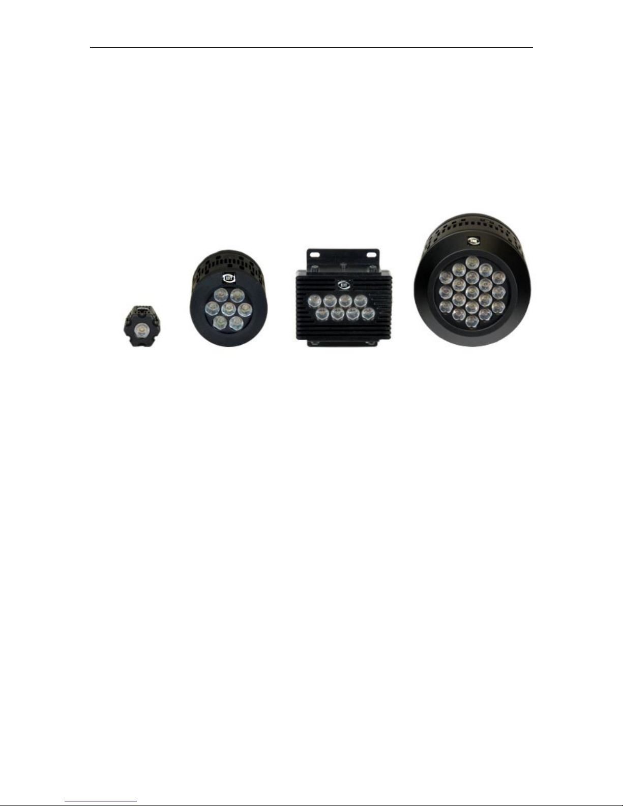
1.2. LED-based Light models and part numbers
The second-generation LED models and part numbers are shown in the table below:
Description Part Number
Honeycomb 1-LED Light Head MM-LED
Honeycomb 1-LED 8 ports controller and power supply MM-CON
Constellation 7-LED Light Head and power supply 7-LED
Constellation 8 LED Light head 8-LED
Constellation 8-LED 4 ports controller and power supply 8-CON
Constellation 19-LED Light Head and power supply 19-LED
External dongle for 100% duty cycle LED-ON
Users Manual
5
Page 6

IDT LED Lights
1.3. General specifications
The specifications of all the LED-light models are shown below.
Description Value
LED
Type Luxeon K2
Light color
Color temperature 4500K – 10000K
Life (measured when output falls to 75% of maximum) 50,000 Hours
Switching times
Rise time < 50 ns
Fall time < 50 ns
Delay time (from input signal) < 100 ns
Sync In
Pulse Frequency 100 KHz
Pulse Duty cycle 0 to 100%
Sync In Voltage 3.3 V (CMOS) or 5.0 V (TTL)
Sync In protection 50 V
Sync In impedance 20 KΩ
Sync Out
Sync Out Voltage 0 to 5 V (TTL)
Sync Out impedance 75 Ω
Cool white
6
User Manual
Page 7

IDT LED Lights
1.4. Connectors Pin-Out
Control connector
PIN Number Value
1 Signal
2 + 12 V
3 GND
4 GND
The control connector is designed to connect the LED lights to one of IDT Galileo™ devices.
The +12 V pin provides power to the device and the device provides the correct square wave
signal to the light system via the signal pin.
An external signal source that generates 3.3 V signals can be connected to the control
connector and replace the Sync In connector.
4 pins power connector (7 and 19 LED systems)
PIN Number Value
1 + 36 V
2 GND
3 GND
4 + 36 V
Users Manual
7
Page 8

IDT LED Lights
1.5. Warranty
IDT, Inc. provides warrants to the original purchaser that, from the date of delivery, the
hardware components of the LED Light System (the “Product”) will be in good working
condition for a period of one (1) year on all parts. Should any of the components of this
Product fail to be in good working order at any time during this warranty period, IDT, Inc. will
either repair or replace those components at its factory at no additional cost. This warranty
does not include service to repair damage to the Product caused by accident, disaster,
misuse, abuse, or non-IDT modification of the Product. All service shipments to IDT must be
sent pre-paid. Warranty service may be obtained by contacting IDT in writing during the
warranty period.
Integrated Design Tools, Inc.
1202 E Park Ave
TALLAHASSE, FL 32301
Attn.: Service Department
T: (850) 222-5939
F: (850) 222-4591
Note: It is requested that the product be returned to INTEGRATED DESIGN TOOLS, Incorporated for
warranty service in its original packaging.
CAUTION: opening or removing the housing of the LED light or the cover of the power supply
may expose you to the risk of electric shock, and may cause the LED system failure. DO
NOT OPEN THE HOUSING OF THE LED OR THE COVER OF THE POWER SUPPLY. TO
DO SO COULD VOID YOUR WARRANTY.
8
User Manual
Page 9
IDT LED Lights
22.. LLEEDD--bbaasseedd lliigghhtt mmooddeellss
2.1. 1-LED Honeycomb System with Controller
The picture above shows a honeycomb LED light with the 8-port controller. The controller is
capable of driving 8 single LED lights. Each LED has a unique inter-connectable design that
allows the lights to be connected together for infinite configurations. Both the single LED and
the controller are crash-rated for automotive applications. The table below shows the
specifications. Lights are now shipping with second-generation features.
1-LED 1st Gen 2nd Gen
Power supply 12 V – 10 A
Power consumption (8 LED) 130 W
Reflected beam angle degrees
Reflected cone diameter at 1 m -
Maximum duty cycle 25 %
Density of light (30 cm) 3,200 Lux
Density of light (60 cm) 830 Lux
Density of light (90 cm) 330 Lux
-
12 V – 10 A
60 W
-
-
100 %
4,800 Lux
1,250 Lux
500 Lux
Users Manual
9
Page 10
IDT LED Lights
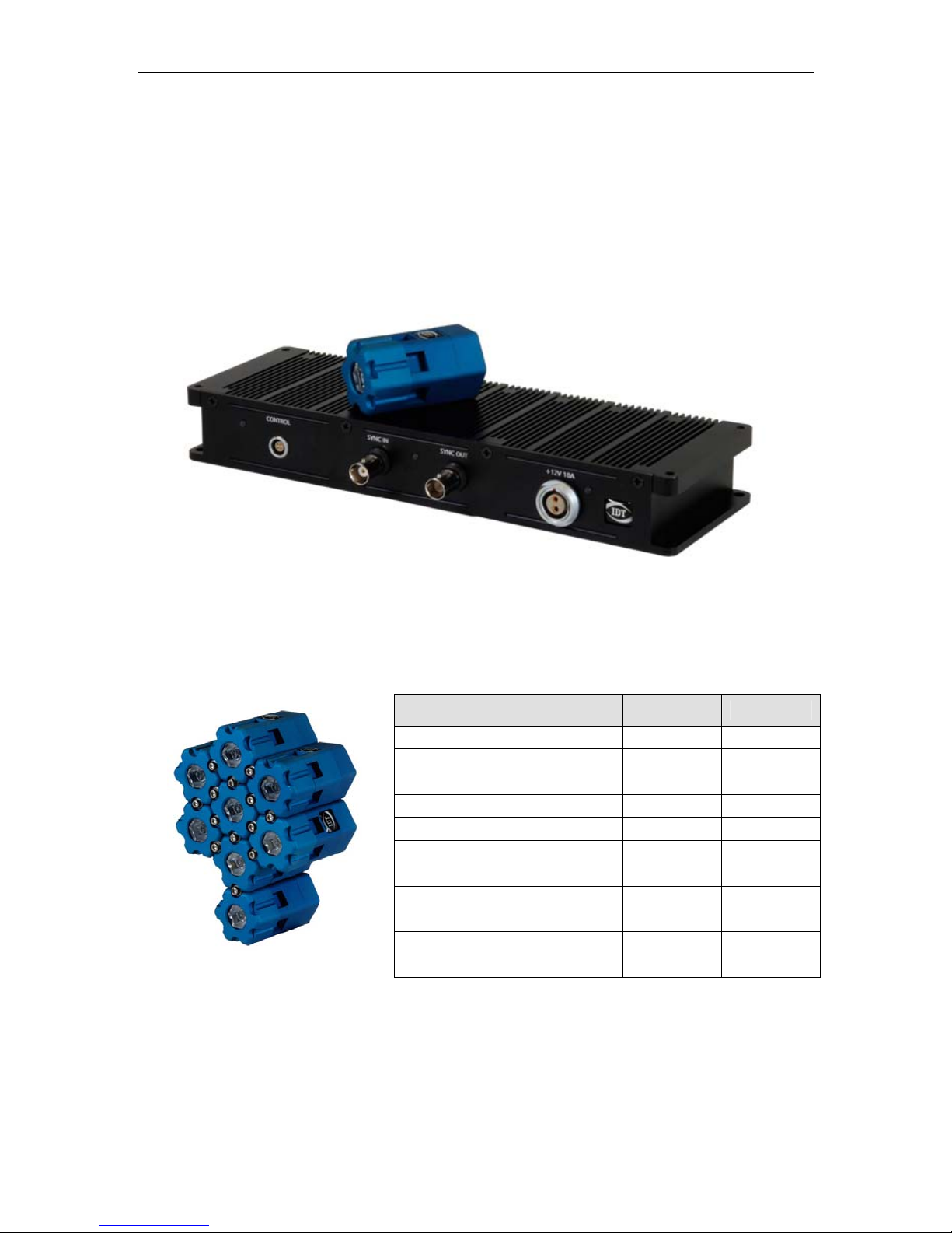
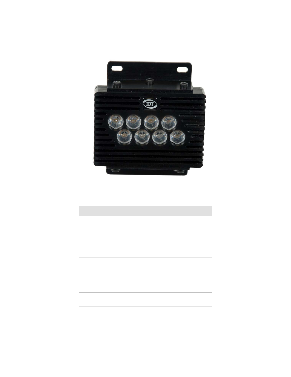
2.2. 8-LED Constellation System with Controller
The 8-LED constellation cluster uses a remote controller to simultaneously operate up to 4
units with a total number of 32 synchronized LED lights. Each cluster is compact, ruggedized
for outdoor applications and crash rated for automotive tests.
Description 8-LED (2nd gen)
Power supply
Power consumption
Reflected beam angle degrees
Reflected cone diameter at 1 m
Maximum duty cycle
Density of light (30 cm)
Density of light (60 cm)
Density of light (90 cm)
Density of light (1.5 m)
Density of light (3 m)
12 V – 10 A
80 W
-
-
100 %
25,000 Lux
Not measured
Not measured
2,500 Lux
Not measured
10
User Manual
Page 11

IDT LED Lights
2.3. 7-LED and 19-LED Constellation Systems
2.3.1. Overview
The 7-LED and 19-LED clusters include 7 or 19 single LED in a compact and light weight
enclosure. The beam is collimated. Both are trigger ready for synchronization with digital
cameras.
7-LED Specificatons 1st Gen 2nd Gen
Power supply 36 V – 1.67 A 36 V – 1.67 A
Power consumption 60 W 60 W
Reflected beam angle degrees
Reflected cone diameter at 1 m 250 mm 250 mm
Maximum duty cycle 250% 100 %
Density of light (30 cm) 15,000 Lux 22,000 Lux
Density of light (1.5 m) 1,500 Lux 2,200 Lux
12,5° 12,5°
19-LED Specificatons 1st Gen 2nd Gen
Power supply 36 V – 4.2 A 36 V – 4.2 A
Power consumption 130 W 130 W
Reflected beam angle degrees
Reflected cone diameter at 1 m 250 mm 250 mm
Maximum duty cycle 25 % 100 %
Density of light (30 cm) 40,000 Lux 60,000 Lux
Density of light (1.5 m) 4,000 Lux 6,000 Lux
12,5° 12,5°
Users Manual
11
Page 12

IDT LED Lights
2.3.2. Back panel and connectors
Sync OUT Connector
And LED
Sync IN Connector
And LED
Control Connector
Power LED
Power Connector
(36 V 3 A)
12
User Manual
Page 13

IDT LED Lights
2.4. Dongle for 100% duty cycle operation
The second-generation LED lights require an additional tool to operate at 100% continuous
duty cycle. The light weight and size dongle is equipped with a C battery that provides the
necessary voltage for 100 % duty cycle to run the lights in continuous mode.
Users Manual
13
Page 14

IDT LED Lights
33.. MMeecchhaanniiccaall aanndd hhoollee mmoouunnttss
3.1. Legend
The drawings with the main dimensions of the LED-based lights are below. The dimensions
are in inches and millimeters (in square brackets).
14
User Manual
Page 15

IDT LED Lights
3.2. 1-LED Honeycomb
3.2.1. Bottom View
Users Manual
15
Page 16

IDT LED Lights
3.2.2. Front View
16
User Manual
Page 17

IDT LED Lights
3.2.3. Side View
Users Manual
17
Page 18

IDT LED Lights
3.2.4. Isometric View
18
User Manual
Page 19

IDT LED Lights
3.3. 8-LED Constellation
3.3.1. Top View
Users Manual
19
Page 20

IDT LED Lights
3.3.2. Bottom View
20
User Manual
Page 21

IDT LED Lights
3.3.3. Side Views
Users Manual
21
Page 22

IDT LED Lights
3.3.4. Isometric View
22
User Manual
Page 23

IDT LED Lights
3.4. 7-LED Constellation
3.4.1. Bottom View
Users Manual
23
Page 24

IDT LED Lights
3.4.2. Back View
24
User Manual
Page 25

IDT LED Lights
3.4.3. Side View
Users Manual
25
Page 26

IDT LED Lights
3.4.4. Isometric View
26
User Manual
Page 27

IDT LED Lights
3.5. 19-LED Constellation
3.5.1. Bottom View
Users Manual
27
Page 28

IDT LED Lights
3.5.2. Back View
28
User Manual
Page 29

IDT LED Lights
3.5.3. Side View
Users Manual
29
Page 30

IDT LED Lights
3.5.4. Isometric View
30
User Manual
Page 31

IDT LED Lights
44.. TTrroouubblleesshhoooottiinngg
4.1. Troubleshooting the LED Light
Symptom Possible Remedy
Connect the power connector from the Power
Outlet to the back panel of the power supply. Then
The power LED is not ON
I have a first-generation LED
system and the light is not emitting.
connect the power supply 4-pins connector to the
back panel of the LED light (or the 2 pins power
connector to the “power in” of the controller).
Make sure that the “Sync In” connector is
connected to a device that generates a TTL square
wave (camera, timing generator) and that the
device is ON.
For a 100% continuous duty cycle make sure that
you have restarted the LED light after
disconnecting from a sync generator. If you have
just powered up the light and the problem persists,
contact the IDT technical support.
I have a second generation LED
system and the light is not emitting
The “Sync In” LED is not blinking
The “Sync Out” LED is not blinking
Make sure that the sync In connector is connected
to a device that generates a TTL square wave
(camera, timing generator) and that the device is
ON.
Make sure that the 100% continuous duty cycle
dongle is connected to the “Sync In” connector.
If one of the above conditions is true and the
problem persists, contact the IDT technical support.
Make sure that the “Sync In” connector is
connected to a device that generates a TTL square
wave (camera, timing generator) and that the
device is ON.
Make sure that the “Sync In” connector is
connected to a device that generates a TTL square
wave (camera, timing generator) and that the
device is ON.
Make sure that the Sync In LED is blinking.
If one of the above conditions is true and you still
do not see the Sync Out LED blinking, contact the
IDT technical support.
Users Manual
31
 Loading...