

id Systems VAC03 User Manual

I.D. SYSTEMS, INC.
VAC™ – Vehicle Asset Communicator™
A Wireless Fleet Management Device
VAC
User’s Guide
Version 3.1.x
VAC™ – A WIRELESS FLEET MANAGEMENT DEVICE
V AC – User’s Guide
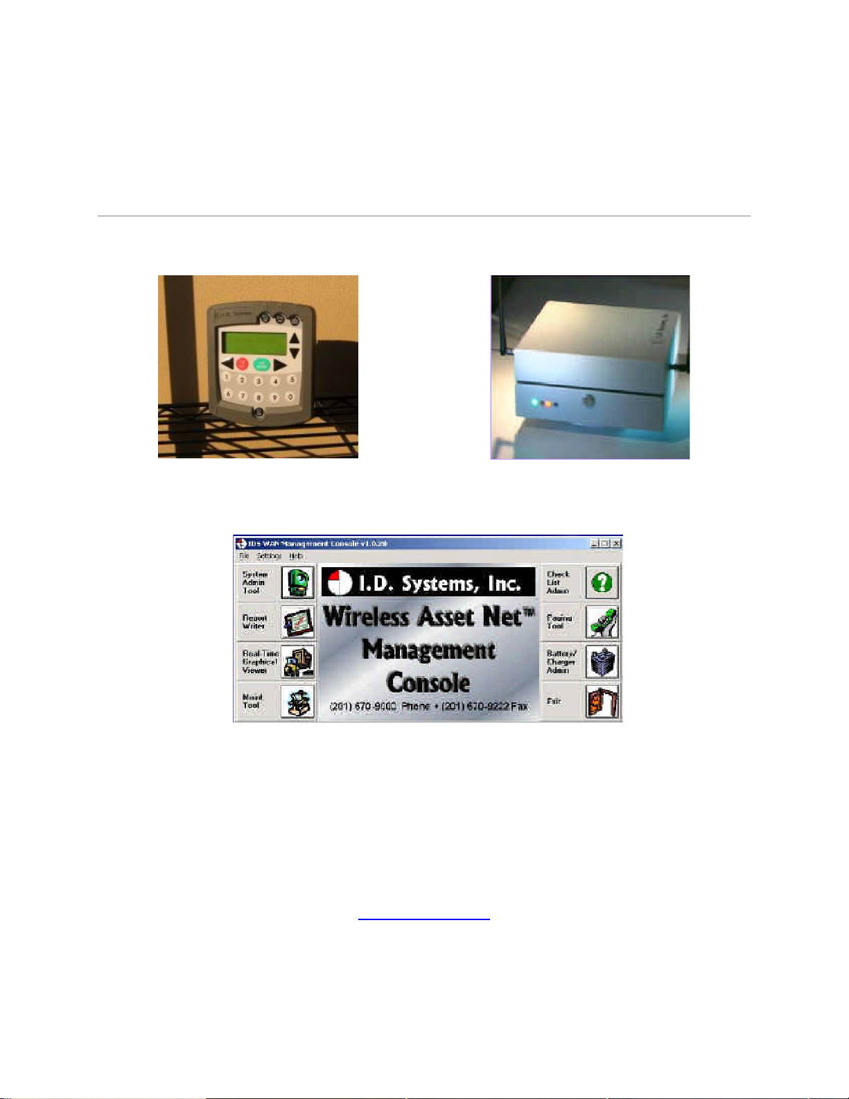
VAC™ IDS Gateway™
IDS WAN Console™
© I.D. Systems, Inc.
1 University Plaza • 6
th
Floor
Hackensack, NJ 07601
Phone 201.996.9000 • Fax 201.996.9144
www.id-systems.com

Preface
This manual is a user’s guide for the VAC (Vehicle Asset Communicator), a Wireless Fleet Management
Device developed by I.D. Systems, Inc. This guide provides the instruction necessary for someone to
install, operate and maintain the VAC device in a vehicle. Note: This user’s guide may change without notice due to
enhancements or changes to VAC.
Related Documents
Vehicle Survey (Doc. #: 026-1000-01)
Publication History
Version Date Changes
2.5.x 9.18.02 Initial
2.6.x 10.25.02 New Modules: Seatbelt monitor & Battery rotation, new
installation screens and color coded connector labels
2.7.x 01-03-03 Add Ext Reader Test, Ext LED Test, Security Features
2.8.x 08-07-03 Add Critical OSHA Shutdown, Blank VAC In Motion
3.0.x 11-03-03 Now Using New Enclosure
3.1.x 03-11-04 O/T versions for new enclosure
Disclaimer and Limitation of Liability
I.D. Systems, Inc. assumes no responsibility for any damage or loss resulting from the use of its products
or services. I.D. Systems assumes no responsibility for any loss or claims by third parties, which may arise
through the use of its products or services.
The information disclosed herein is the exclusive property of I.D. Systems and no part of this information
may be reproduced or transmitted in any form or by any means including electronic storage, reproduction,
execution or transmission without the prior written consent of I.D. Systems. The information contained
in this document is subject to change without notice and should not be construed as a commitment by
I.D. Systems unless such commitment is expressly given in writing.

FCC Compliance Statement
Compliance Statement (Part 15.19)
This device complies with Part 15 of the FCC Rules. Operation is subject to the following two
conditions:
1. This device may not cause harmful interference, and
2. This device must accept any interference received,
including interference that may cause undesired operation.
Warning (Part 15.21)
Changes or modifications not expressly approved by the party responsible for compliance could void the
user’s authority to operate the equipment.
Compliance Statement (Part 15.247)
This device complies with Part 15.247 of the FCC rules. Operation is subject to the following condition:
To comply with FCC’s RF exposure limits for general population/uncontrolled exposure, the antenna(s)
used for this transmitter must be installed to provide a separation distance of atleast 20cm from all
persons and must not be co-located or operating in conjunction with any other antenna or transmitter.

TableofContents
T able of Contents
TABLE OF CONTENTS ......................................................................................................................................................................................... 5
INTRODUCTION ...................................................................................................................................................................................................... 7
SYSTEM OVERVIEW ................................................................................................................................................................................................ 7
INSTALLATION ....................................................................................................................................................................................................... 9
WARNINGS ............................................................................................................................................................................................................ 9
STANDARD HARDWARE FOR INSTALLATION .................................................................................................................................................... 9
TOOLS REQUIRED FOR INSTALLATION (NOT SUPPLIED) ............................................................................................................................. 9
SYSTEM CONNECTIONS OVERVIEW ................................................................................................................................................................. 10
INSTALLATION SUMMARY ................................................................................................................................................................................... 10
BEFORE STARTING THE INSTALLATION .......................................................................................................................................................... 10
INSTALLING THE VAC (AND OPTIONAL ID READER) ................................................................................................................................... 11
Selecting the VAC Mounting Location .............................................................................................................................................................. 11
Mounting the VAC ............................................................................................................................................................................................. 11
INSTALLING VAC-TO-PCM HARNESS ............................................................................................................................................................ 12
Vehicle Cable Harness ...................................................................................................................................................................................... 12
Selecting the System’s Power and Ground Connections .................................................................................................................................. 12
FINISHING THE INSTALLATION .......................................................................................................................................................................... 13
System Configuration ........................................................................................................................................................................................ 13
STANDARD VAC OPERATION ....................................................................................................................................................................... 14
VAC OVERVIEW .................................................................................................................................................................................................... 14
GENERAL OPERATION .......................................................................................................................................................................................... 15
BASIC OPERATION: LCD, KEYPAD, ID READER AND LEDS .................................................................................................................... 16
VAC Display and Keypad Basics ...................................................................................................................................................................... 16
ID Reader .......................................................................................................................................................................................................... 16
Menu Selection Mode ........................................................................................................................................................................................ 16
Digit Entry Mode............................................................................................................................................................................................... 17
ACCESS CONTROL (ALL USERS): LOGGING ON AND OFF THE VEHICLE ............................................................................................... 18
Access Control Overview .................................................................................................................................................................................. 18
Logging onto the VAC ....................................................................................................................................................................................... 19
Denial of Login ................................................................................................................................................................................................. 21
NOTE: Repeated failure to log into the VAC will trigger an alert on the ARDCS which can be emailed or sent by pager to specified
personnel (See ARDCS User’s Guide). ............................................................................................................................................................ 22
I.D. Systems, Inc. One University Plaza, Hackensack, NJ 07601 000-0144-01
Tel: 201-996-9000; Fax 201-996-9144; email: support@id-systems.com Page 5 of 41

VACUser’sGuide
Logging Off of the VAC ..................................................................................................................................................................................... 23
ELECTRONIC OSHA SAFETY CHECKLISTS (ALL USERS) .......................................................................................................................... 23
OSHA Question Mode ....................................................................................................................................................................................... 24
Critical OSHA Shutdown (Optional) ................................................................................................................................................................ 26
TWO-WAY TEXT PAGING (ALL USERS) .......................................................................................................................................................... 26
Viewing and Responding to Text Pages ............................................................................................................................................................ 27
VEHICLE UTILIZATION MONITORING (ALL USERS) ..................................................................................................................................... 29
MOTION SAFETY FEATURE (OPTIONAL – STANDARD AND MASTER USERS) ........................................................................................ 30
BATTERY ROTATION (OPTIONAL MODULE - ALL USERS) .......................................................................................................................... 3 0
Battery Request: ................................................................................................................................................................................................ 31
Battery Validation: ............................................................................................................................................................................................ 32
Battery Request Troubleshooting: .................................................................................................................................................................... 33
SECURITY MODULE (OPTIONAL MODULE - ALL USERS) ............................................................................................................................ 33
GRANTING TEMPORARY ACCESS (MASTER USERS) ................................................................................................................................... 33
APPENDIX A............................................................................................................................................................................................................ 35
ELECTRICAL ............................................................................................................................................................................................................ 35
MEMORY/OTHER.................................................................................................................................................................................................... 35
COMMUNICATION .................................................................................................................................................................................................. 35
USER INTERFACE .................................................................................................................................................................................................. 36
ENVIRONMENTAL .................................................................................................................................................................................................. 37
MOUNTING .............................................................................................................................................................................................................. 37
APPENDIX B............................................................................................................................................................................................................ 38
VAC™ ERROR CODE GUIDE .............................................................................................................................................................................. 38
Error Code: E3301 ........................................................................................................................................................................................... 38
APPENDIX C............................................................................................................................................................................................................ 39
WARRANTY INFORMATION .................................................................................................................................................................................. 39
Limited Warranty .............................................................................................................................................................................................. 39
This Warranty Does Not Cover: ....................................................................................................................................................................... 39
General Provisions: ........................................................................................................................................................................................... 40
To Get Warranty Service or Returned Material Authorization: ....................................................................................................................... 40
I.D. Systems, Inc. One University Plaza, Hackensack, NJ 07601 000-0144-01
Tel: 201-996-9000; Fax 201-996-9144; email: support@id-systems.com Page 6 of 41

Introduction
Introduction
This manual is a user’s guide for the VAC (Vehicle Asset Communicator), a Wireless Fleet Management
Device developed by I.D. Systems. This guide will introduce the reader to the VAC and to I.D. Systems’
Fleet Management solution. In addition, this guide also includes information about VAC installation
procedures, installation options, operator instructions, maintenance procedures, and troubleshooting. The
owner and user of a VAC can use this guide to understand how a VAC works and how to interact with it.
The Introduction section covers general information about the IDS Fleet Management System, and what
part the VAC device plays in the system. Users of the IDS Fleet Management System should familiarize
themselves with this information to better understand the detailed instructions in this guide.
The Installation section provides detailed procedures and guidelines for hardware installation.
Electricians, mechanics or maintenance persons responsible for VAC installation or troubleshooting
should familiarize themselves with this hardware installation process. This will allow them a better
understanding of the interface between the VAC and the vehicle being managed. In addition, those who
perform vehicle maintenance will better understand the implications of parts replacement or rewiring.
Finally, VAC troubleshooting is more easily understood with an understanding of hardware installation
procedures and guidelines. In order to complete VAC installation, maintenance user software, covered in
the VAC Operation section is required.
The Standard VAC Operation section explains how the user interacts with the VAC user interface
(keypad, display and ID reader). As a mini-computer, the VAC is an interactive device requiring an
operator to interact with it. Standard operators (vehicle drivers) must familiarize themselves with the
section on Basic Operation, Access Control, Electronics, OSHA Checklists, and Two-Way Text Paging,
either through reading the Guide, or through hands-on training. Floor supervisors with special system
privileges (Master Users) should also become familiar with the Master User features.
The appendices include additional information for those who have purchased or who maintain the VAC.
Appendix A details the physical specifications of the system, which is useful for those who wish to
understand how the VAC will work in specific environments. Appendix B is a troubleshooting guide for
maintenance personnel to handle issues with the VAC that may arise through installation or operation.
Finally, Appendix C covers warranty information for those who have purchased the VAC product.
System Overview
The VAC is part of a comprehensive fleet management solution, integrating access control, vehicle
I.D. Systems, Inc. One University Plaza, Hackensack, NJ 07601 000-0144-01
Tel: 201-996-9000; Fax 201-996-9144; email: support@id-systems.com Page 7 of 41
VACUser’sGuide
monitoring, safety, maintenance and communication technology in an industrial vehicle. Within the VAC,
a processor is integrated with an RF transceiver and vehicle interface and runs an embedded computer
application. Information about the attached vehicle is communicated from the VAC over the wireless
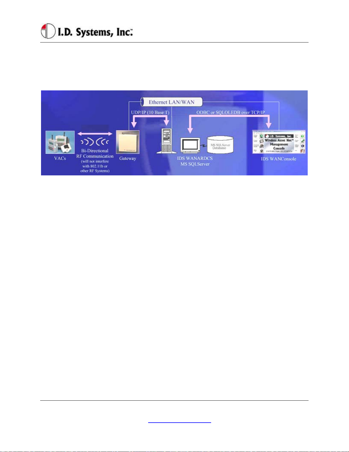
infrastructure of Gateways™, to I.D. Systems software (refer to the system diagram in Figure 1).
Figure 1: IDS Fleet Management System Diagram
The VAC device both sends and receives information, such as access control updates, pages, updated
configuration settings, and scheduled maintenance event information, and interacts with the vehicle’s
driver using a keypad, display, and optional ID readers.
I.D. Systems, Inc. One University Plaza, Hackensack, NJ 07601 000-0144-01
Tel: 201-996-9000; Fax 201-996-9144; email: support@id-systems.com Page 8 of 41

Installation
Installation
WARNINGS
* Please read this document in its entirety
BEFORE performing any installation. *
* Please disconnect main vehicle battery
BEFORE performing any installation. *
Standard Hardware for Installation
The standard components of the VAC system are installed on every vehicle type (Industrial Electric and
Internal Combustion). The following is a list of standard equipment that is required to install each VAC
system:
900-0144-02: Universal Vehicle Asset Communicator (VAC)
810-0113-0x: VAC-to-PCM Cable
835-0121-01 and -03: Mounting Hardware Assortments
825-0111-01: Vehicle Asset Communicator Mounting Bracket
During hardware installation and system configuration, a test sheet must be filled out and sent (via mail or
fax) to I.D. Systems, Inc. to certify that the installation was performed correctly. The test sheet is
provided with the hardware.
For technical support, contact I.D. Systems, Inc.:
By Phone: (201) 996-9000
By Fax: (201) 996-9144
By email: support@id-systems.com
Tools Required for Installation (Not Supplied)
In order to install the standard components of the VAC system, certain tools are required. The VAC is
mounted rigidly to each vehicle, thus requiring mounting hardware (supplied in Mounting Hardware
Assortment kits) and requiring holes to be drilled. In addition to mechanical mounting, some wiring and
electrical testing must be performed. Therefore, wire strippers and simple electrical test equipment are
required.
MOLEX RHT-1991 Ratchet tool or equivalent
I.D. Systems, Inc. One University Plaza, Hackensack, NJ 07601 000-0144-01
Tel: 201-996-9000; Fax 201-996-9144; email: support@id-systems.com Page 9 of 41

VACUser’sGuide
Minimum ¼” chuck drill
¼” drill bit
1 ¼” or 1 ½” hole saw
#10 socket and ratchet (or open-end wrench)
Medium sized slotted and Phillips screwdrivers
Wire stripper
Multimeter and test lead assortment
Note: The system is shipped with a set of hardware used to install the system on a vehicle (Mounting
Hardware Assortment kits). The hardware should accommodate most vehicle types. The hardware kit is
specified for high vibration industrial applications. I.D. Systems highly recommends using the MOLEX
RHT-1991 Ratchet tool (or equivalent) for crimping terminals. If using a different tool, I.D. Systems will
bear no responsibility for resulting installation failures.
System Connections Overview
Figure 2: System Diagram
1. VAC: Vehicle Asset Communicator. User interface and intelligent industrial control device.
Operators read the display and use the keypad to interact with the vehicle control system. A twoway radio transceiver is embedded within the VAC.
2. VAC-to-PCM Cable: Cable that connects the VAC to the vehicle’s Power and Control system.
This cable must route from the VAC mounting location (driver area) to the vehicle (typically the
engine/motor compartment).
Installation Summary
The installation must be performed in the order that follows:
Installing the VAC (with optional ID reader) [Items 1, 2]
Configuring the VAC using On-Screen Display
Before Starting the Installation
Before starting a VAC installation, make sure that all required tools and equipment and the Installation
I.D. Systems, Inc. One University Plaza, Hackensack, NJ 07601 000-0144-01
Tel: 201-996-9000; Fax 201-996-9144; email: support@id-systems.com Page 10 of 41

Installation
Verification test sheet are available. If not, do not proceed with installation. If all equipment is
available, record the following on the installation sheet:
The VAC serial number
Installing the VAC (and optional ID Reader)
The VAC contains the driver’s user interface to the system and also contains the embedded fleet
management software and RF capability. The VAC, therefore, must be mounted in a location that is
convenient for operator access (to the keypad, LCD and optional ID reader) and that is optimized for RF
performance. The VAC is wired into the vehicle. Therefore, selecting the proper location and verifying
correct installation is important to ensure correct functionality.
Selecting the VAC Mounting Location
Notes:
The VAC is mounted to the vehicle using the supplied VAC Mounting Bracket (modifications or
custom brackets must be approved by I. D. Systems in order to ensure proper functionality).
Procedure:
Select a location on the dash area of the vehicle to mount the VAC.
o The operator of the vehicle should be able to view the VAC’s display and access the
keypad and optional ID reader while sitting in the vehicle.
o The VAC should not obscure the operator’s line of sight or accessibility to the vehicle.
o The VAC display should not be obscured.
o The VAC’s antenna should be as far away from the vehicle’s chassis as possible (having
the antenna close to the metal of the vehicle [less than 3”] attenuates the unit’s RF
communications).
o The VAC should be securely affixed to the vehicle and is not adjustable for different
operator heights.
Select the location on the vehicle to which the bracket should be bolted or welded.
Mounting the VAC
If mounting with bolts, use the bracket as a template to drill holes in the vehicle for mounting the
VAC bracket. The bracket has to be secured to the vehicle by at least two bolts. Make sure that
nothing can be damaged on the vehicle while drilling or welding.
If the VAC-to-PCM cable has to run through the dash of the vehicle, drill using a 1¼” hole saw.
Assemble the VAC onto the Bracket.
If the VAC-to-PCM cable runs through the vehicle’s dash, insert a Grommet (supplied) in the
hole to prevent the cable from being damaged.
I.D. Systems, Inc. One University Plaza, Hackensack, NJ 07601 000-0144-01
Tel: 201-996-9000; Fax 201-996-9144; email: support@id-systems.com Page 11 of 41

VACUser’sGuide
Using the attached hex key tighten the hex nuts to secure the swivel points. The bracket is not
supposed to be adjustable. Failure of tightening the hex nuts will result in assembly failure.
Attach the 9-pin circular connector of the VAC-to-PCM cable (Item 4) to the circular connector
on the back of the VAC.
Route the VAC-to-PCM cable through the hole in the VAC mounting bracket and route all the
way to the vehicle interface location.
o Use the vehicle’s pre-existing cable-routing channels (where other cables are also run
throughout the vehicle) to prevent the cable from being damaged during vehicle use or
maintenance.
Installing VAC-TO-PCM Harness
The VAC-TO-PCM Harness connects the VAC to the vehicle. Through the harness, the VAC system
will get power from the vehicle, and have the ability to receive commands from the vehicle via the I.D.
Systems Serial Data Interface (IDSY SDI) protocol. Installation of this cable must be performed
according to the instructions below for the VAC system to operate properly.
Vehicle Cable Harness
Cable Pin-Out:
Pin Color Signal Name Comments
1 RED POWER Power (+)- TO REGULATED 6.5 VDC
2 BLACK POWERRTN Power return (-) - TO 6.5 VDC RETURN
3 WHITE ISEN(-) IDSY SDI SIMO (OPTIONAL)
4 GREEN RELAYIN IDSY SDI SOMI (OPTIONAL)
5 ORANGE RELAYOUT IDSY SDI SCLK (OPTIONAL)
6 BLUE VSEN1(-) IDSY SDI INT_NCS (OPTIONAL)
7 WHITE/
VSEN1(+) IDSY SDI INTRPT (OPTIONAL)
BLACK
8 RED/
VSEN2(+) IDSY SDI WAKEUP (OPTIONAL)
BLACK
9 RED/
N/C NO CONNECT
BLACK
Selecting the System’s Power and Ground Connections
Notes:
I.D. Systems, Inc. One University Plaza, Hackensack, NJ 07601 000-0144-01
Tel: 201-996-9000; Fax 201-996-9144; email: support@id-systems.com Page 12 of 41

Installation
The system requires an uninterrupted, regulated 6.5 VDC supply from the vehicle. The
supply should be continuous regardless of the condition of the vehicle. The only time the supply
is discontinued is when the vehicle’s battery is unplugged.
The interface should be the cleanest possible power source, free from noise and damaging voltage
spikes.
The current draw of the system in normal mode at 6.5 VDC is approximately 0.25 Amperes
Finishing the Installation
System Configuration
In order to complete the installation of the VAC system on a vehicle and to ensure proper operation of
the system.
I.D. Systems, Inc. One University Plaza, Hackensack, NJ 07601 000-0144-01
Tel: 201-996-9000; Fax 201-996-9144; email: support@id-systems.com Page 13 of 41
 Loading...