

IDS GeoRadar s r l SRS FW400 User Manual
INGEGNERIA DEI SISTEMI S.p.A.
Safe Rail System User Guide
Rev. 1.2
Protocol: MN/2009/030
Compiled by
Valter Baroncini
Controlled by
Stefania Bracciali
Approved by
Laura Della Maggiore
Authorised by
Guido Manacorda
Signature Date
August 2009

IDS Ingegneria Dei Sistemi S.p.A. Protocol: MN/2009/030 - Rev. 1.2
Safe Rail System Data Acquisition Software
Document Evolution
Revision Date Reason for modification
Rev. 1.0 March 2009 First edition
Rev. 1.1 July 2009 Add of Mechanical kit
Rev 1.2 August 2009 FCC information added
SW Versions covered by this document
01.03.001, 01.06.001, 01.07.006, 01.07.007.
OUR CONTACTS
IDS Ingegneria dei Sistemi S.p.A. – GeoRadar Division
Via Sterpulino, 20
56121 Ospedaletto (PISA) - ITALIA
Tel: +39.050.967111
Fax: +39.050.967121
inforis@ids-spa.it
Customer Care department:
customercare.gpr@ids-spa.it
Tel.: +39.050.967122
Sales & Marketing department:
sales.gpr@ids-spa.it
Tel.: +39.050.967123/24/43
2 / 76

IDS Ingegneria Dei Sistemi S.p.A. Protocol: MN/2009/030 - Rev. 1.2
CONSEQUENCES OF AN
PROCESSING AND
Y MUST NOT BE
HEY
E USER MUST NOT
BY THEM TO GIVE THE
IDS INGEGNERIA DEI SISTEMI SPA ASSUMES NO LIABILITY FOR ANY
DIRECT, INDIRECT, SPECIAL, INCIDENTAL OR CONSEQUENTIAL DAMAGES
OR INJURIES CAUSED BY SUCH RELIANCE ON THE ACCURACY,
RELIABILITY, OR TIMELESS OF THE INFORMATION PROVIDED BY THOSE
ANY PERSON OR ENTITY WHO RELIES ON INFORMATION OBTAINED FROM
THE AUTOMATED DATA PROCESSING/ANALYSIS TOOLS ONLY, DOES SO AT
Safe Rail System Data Acquisition Software
DISCLAIMER
IDS WILL NOT BE HELD RESPONSIBLE FOR THE
IMPROPER USE OF THE EQUIPMENT AND/OR THE SOFTWARE.
THIS SOFTWARE MAY INCLUDE AUTOMATED DATA
ANALYSIS TOOLS.
WHILE EVERY EFFORT IS MADE TO ENSURE THE ACCURACY OF THE
INFORMATION PROVIDED BY THOSE TOOLS, THE
INTENDED AS A SUBSTITUTE FOR INTELLIGENT ANALYSIS; RATHER, T
HAVE TO BE INTENDED AS AN ADVISOR AND TH
COMPLETELY RELY ON THE RESULTS PROVIDED
COMPLETE ANSWER.
TOOLS.
HIS OR HER OWN RISK
3 / 76

IDS Ingegneria Dei Sistemi S.p.A. Protocol: MN/2009/030 - Rev. 1.2
The equipment conforms to the following requirements set by EC
uding subsequent modifications, and to the legislation set
Warning: this equipment is destined for use in industrial environments
rcial and light industry
environments, this apparatus may generate radio interference: in this case,
the user may be required to operate while taking appropriate
,
Safe Rail System Data Acquisition Software
SAFETY INFORMATION
regulations, incl
by the member states that implement these regulations:
1999/05/EEC Radio Directive
(Class A apparatus). In residential, comme
countermeasures.
The apparatus is sensitive to the presence of external electromagnetic fields
which may reduce its performance.
4 / 76

IDS Ingegneria Dei Sistemi S.p.A. Protocol: MN/2009/030 - Rev. 1.2
Warning: Changes or modifications to this unit not expressly approved by the party
Safe Rail System Data Acquisition Software
IMPORTANT NOTE FOR THE US CUSTOMERS
FCC ID: UFW-SRS-FW400
This device complies with part 15 of the FCC Rules:
Operation is subject to the following conditions:
1. This device may not cause harmful interference, and
2. This device must accept any interference received, Including interference that may cause undesired operation
responsible for compliance could void the user’s authority to operate the equipment.
Operation of this device is restricted to law enforcement, fire and rescue officials, scientific research institutes,
commercial mining companies, and construction companies. Operation by any other party is a violation of 47 U.S.C. §
301 and could subject the operator to serious legal penalties.
Coordination Requirements
(a) UWB imaging systems require coordination through the FCC before the equipment may be used. The operator shall
comply with any constraints on equipment usage resulting from this coordination.
(b) The users of UWB imaging devices shall supply detailed operational areas to the FCC Office of Engineering and
Technology who shall coordinate this information with the Federal Government through the National
Telecommunications and Information Administration. The information provided by the UWB operator shall include the
name, address and other pertinent contact information of the user, the desired geographical area of operation, and the
FCC ID number and other nomenclature of the UWB device. This material shall be submitted to the following address:
Frequency Coordination Branch., OET
Federal Communications Commission
445 12th Street, SW
Washington, D.C. 20554
ATTN: UWB Coordination
(d) Users of authorized, coordinated UWB systems may transfer them to other qualified users and to different locations
upon coordination of change of ownership or location to the FCC and coordination with existing authorized operations.
(e) The NTIA/FCC coordination report shall include any needed constraints that apply to day-to-day operations. Such
constraints could specify prohibited areas of operations or areas located near authorized radio stations for which
additional coordination is required before operation of the UWB equipment. If additional local coordination is required,
a local coordination contact will be provided.
(f) The coordination of routine UWB operations shall not take longer than 15 business days from the receipt of the
coordination request by NTIA. Special temporary operations may be handled with an expedited turn-around time when
circumstances warrant. The operation of UWB systems in emergency situations involving the safety of life or property
may occur without coordination provided a notification procedure, similar to that contained in CFR47 Section 2.405(a)-
(e), is followed by the UWB equipment user.
Notice: Use of this device as a wall imaging system is prohibited by FCC regulations.
In this manual, instructions that specifically apply to the version of the system
dedicated to the US market, are identified by the following label
5 / 76

IDS Ingegneria Dei Sistemi S.p.A. Protocol: MN/2009/030 - Rev. 1.2
Before cleaning any external parts of the apparatus, make sure
that all cables have been disconnected, including the power
If a damp cloth is used, make sure it is not too wet,
to avoid any damage to the electrical components of the
equipment. Wait until the equipment is totally dry before
The Detector Duo should be cleaned periodically using a damp
Do not apply liquid directly to the electrical contacts of the
various connectors. If a specific spray is used to clean the PC
TFT monitor, make sure it is not flammable; ion any case, do not
ly on the screen, instead, spray it onto the cleaning
Safe Rail System Data Acquisition Software
!
WARNING
CLEANING INFORMATION
supply cable.
reconnecting the cables.
cloth.
Do not use solvents or abrasive detergents.
spray it direct
cloth.
6 / 76
IDS Ingegneria Dei Sistemi S.p.A. Protocol: MN/2009/030 - Rev. 1.2
Safe Rail System Data Acquisition Software
BATTERIES REMOVAL INFORMATION
Laptop Batteries:
Manufacturer: PANASONIC
Type: Li-ion Ni
Characteristics: 10.65V 5.7Ah
Removal instructions:
1. turn off the laptop;
2. open the drawer with the symbol of the batteries;
3. extract the battery pack pulling the tab.
Radar batteries:
Manufacturer: FIAMM FG21202 / SAFT MP176065
Type: rechargeable lead acid / rechargeable lithium-ion
Characteristics: 12V & 12Ah / 15V & 6.8Ah
Removal instructions:
1. disconnect the battery from the instrument:
a. pull the connector wings;
b. separate the connectors;
2. remove the battery from the cover (optional) opening the
strap.
7 / 76

IDS Ingegneria Dei Sistemi S.p.A. Protocol: MN/2009/030 - Rev. 1.2
Safe Rail System Data Acquisition Software
RECICLYING
The crossed out wheeled bin symbol shown on the equipment indicates that
the product must be recycled separately from other waste at the end of its
useful life.
Separate waste disposal of this product at the end of its useful life will be
organised and managed by IDS. When you decide to dispose of the
equipment, contact IDS and follow the system that IDS has set up to permit
the separate collection of the apparatus at its life end.
Adequate separate collection for its subsequent recycling, treatment and
environmental friendly disposal contribute towards avoiding any
unnecessary effects on the environment and to health and favour the reuse or
recycling of the materials that make up the equipment. Unauthorised disposal
of this product as unsorted waste by its possessor will lead to an
administrative penalty foreseen by national regulations.
8 / 76

IDS Ingegneria Dei Sistemi S.p.A. Protocol: MN/2009/030 - Rev. 1.2
Safe Rail System Data Acquisition Software
WARRANTY CERTIFICATE CONDITIONS
1) IDS Ingegneria dei Sistemi S.p.A, hereinafter referred to as IDS, warrants hardware/software
products for a period of 12 months from the delivery date to the original customer;
2) The delivery date is certified by the “Warranty Registration Form”;
3) IDS’s hardware products will be free from defects in materials workmanship under normal use
and service;
4) IDS’s obligation is limited to repairing or replacing parts or equipment which are returned to IDS,
without alteration or further damage, and which in IDS s judgment, were defective or became
defective during normal use;
5) IDS’ software will have to be installed on a PC according to the requirement of the IDS hardware
( see IDS User’s Guide the Software Data Acquisition);
6) IDS’ s software products designed by IDS for use for IDS hardware products are warranted not to
fail to execute their programming instructions due to defects during the warranty period, provided
they are properly installed on IDS hardware products. IDS does not warrant if the IDS software will
be used and operated in hardware and software combinations not selected by IDS;
7) IDS does not assumes any liability for any direct, indirect, special, incidental or consequential
damages or injuries caused by proper or improper operation of its equipment whether defective or
not defective;
8) This software may include automated data processing and analysis tools. While every effort is
made to ensure the accuracy of the information provided by those tools, they must not be intended
as a substitute for intelligent analysis; rather, they have to be intended as an advisor and the user
must not completely rely on the results provided by them to give the complete answer. IDS assumes
no liability for any direct, indirect special, incidental or consequential damages or injuries caused by
such reliance on the accuracy, reliability, or timeliness of the information provided by those tools.
Any person or entity who relies on information obtained from the automated data
processing/analysis tools only, does so at his or her own risk;
9) IDS’s warranty does not extend and shall not apply to:
a) Products which have been repaired or altered by other than IDS personnel;
b) Products which have been subjected to misuse, neglect, accident or improper installation;
c) Products in which have been installed Hardware/Software accessories not supplied by IDS
and/or without any approval by IDS;
d) Products which have been connected to equipment different from the ones supplied by IDS
(except the PC data Logger which must conform to IDS specifications;
e) Products which have been damaged by natural disaster or calamities.
10) Before returning any equipment to IDS , you have to contact the IDS Customer Care Office that
will authorize you to return the material to be repaired;
11) Once the parts/equipment to be repaired arrive to IDS, IDS may inspect the defective products to
verify they are eligible for repair or replacement. All packing must be saved for inspection purpose
in order to assist IDS to understand the cause of the defects. IDS, will not be obliged to repair, or
replace for products returned as defective but damaged from abuse, misuse, neglicence , accident
loss or damage in transit;
12) The final clients, is responsible for ensuring the defective products returned to be properly
packaged;
13) The above warranty are sole and exclusive, and no other warranty, whether written or oral, is
expressed or implied.
9 / 76

IDS Ingegneria Dei Sistemi S.p.A. Protocol: MN/2009/030 - Rev. 1.2
Safe Rail System Data Acquisition Software
INDEX
1. Overview.....................................................................................................................14
1.1 How to use this manual.......................................................................................14
2. The SRS System Hardware configuration..............................................................15
2.1 The SRS_PLUS Control Unit..............................................................................15
2.2 The SRS-FW400 Control Unit ............................................................................16
2.3 The Notebook Computer.....................................................................................18
2.4 Connecting the Control Unit - Notebook Computer...........................................19
2.5 Position radar sensor .........................................................................................22
2.6 Antennas .............................................................................................................24
2.7 Mechanical kit ....................................................................................................25
3. Software configuration of the SRS system..............................................................28
3.1 Software Installation and configuration.............................................................28
4. SRS acquisition software...........................................................................................33
4.1 Starting the SRS_PLUS acquisition software.....................................................33
4.2 Choosing the configuration ................................................................................34
4.3 Setting up the Calibration...................................................................................35
4.3.1 Advanced Settings Menu...........................................................................42
4.4 Choosing a survey...............................................................................................44
4.5 Setting the acquisition parameters .....................................................................46
4.6 Data acquisition..................................................................................................51
4.7 Operating in review mode ..................................................................................55
5. Error messages and alarms.......................................................................................58
5.1 Error messages...................................................................................................58
6. On line assistance.......................................................................................................59
6.1 Remote assistance using Webex Support Center................................................59
6.1.1 How to use the Webex service....................................................................59
Appendix A - Mechanical Requirements for the installation of SRS
SYSTEMS on board a train..........................................................................................62
A.1 - Introduction......................................................................................................62
A.2 - Mechanical requirements.................................................................................62
A.3 - Specifications for the fixing frame ...................................................................64
Appendix B - SRS System technical specifications....................................................66
B.1 - SRS_PLUS System Technical Specifications...................................................66
10 / 76

IDS Ingegneria Dei Sistemi S.p.A. Protocol: MN/2009/030 - Rev. 1.2
Safe Rail System Data Acquisition Software
B.1.1 SRS_PLUS Control Unit specifications......................................................66
B.2 - SRS-FW400 System Technical Specifications..................................................67
B.2.1 Control Unit specifications........................................................................67
Appendix C - Using GPS with the SRS system...........................................................68
Appendix D - Using camera with the SRS system......................................................72
FIGURES INDEX
FIG. 2-1 – VIEW OF CONTROL UNIT, START UP SIDE............................................15
FIG. 2-2 – VIEW OF CONTROL UNIT, ANTENNA CONNECTORS SIDE................16
FIG. 2-3 – SRS-FW400 CONTROL UNIT FRONT PANEL WITH BATTERY PORT,
LAN PORT AND WIRELESS CONNECTOR........................................................17
FIG. 2-4-SRS-FW400 CONTROL UNIT REAR PANEL WITH CONNECTIONS TO
POSITION SENSOR AND ANTENNAS.................................................................17
FIG. 2-5 – SRS ANTENNA WITH A 19 POLE CONNECTOR AND POSSIBILITY OF
A CASCADE CONNECTION..................................................................................18
FIG. 2-6 – PANASONIC TOUGHBOOK CF-30.............................................................18
FIG. 2-7 – LAN CABLE...................................................................................................19
FIG. 2-8 – LAN CABLE CONNECTION BETWEEN THE NOTEBOOK COMPUTER
AND THE CONTROL UNIT (SRS_PLUS).............................................................20
FIG. 2-9 – LAN CABLE CONNECTION BETWEEN THE NOTEBOOK COMPUTER
AND THE CONTROL UNIT (SRS-FW400 ONLY) ...............................................20
FIG. 2-10 – BATTERY CABLE.......................................................................................21
FIG. 2-11 – CONNECTING THE CONTROL UNIT TO THE BATTERY (SRS_PLUS)
...................................................................................................................................21
FIG. 2-12 – BATTERY CABLE.......................................................................................21
FIG. 2-13 – CONNECTING THE CONTROL UNIT TO THE BATTERY (SRS-FW400
ONLY).......................................................................................................................21
FIG. 2-14 – POWER SUPPLY CABLE AND CONNECTION TO THE CONTROL
UNIT..........................................................................................................................22
FIG. 2-15 – POSITION SENSOR .....................................................................................22
FIG. 2-16 – WHEEL PORT ON THE SRS_PLUS CONTROL UNIT ............................23
FIG. 2-17 – WHEEL PORT ON THE SRS-FW400 CONTROL UNIT...........................23
FIG. 2-18 – 400M HZ SRS_PLUS ANTENNA (TOP), SKETCH OF DRAG
DIRECTION (MIDDLE) AND PVC “H” PLATE (BOTTOM )...............................24
FIG. 2-19 –ANTENNA FOR THE SRS-FW400 SYSTEM (RED ARROWS SHOW
DRAGGING DIRECTION)......................................................................................25
FIG. 2-20 – ANTENNA “L” SUPPORTS AND BAR......................................................26
FIG. 2-21 – DOPPLER SUPPORTS.................................................................................26
FIG. 2-22 – SKETCH OF SRS LAYOUT ........................................................................27
FIG. 3-1 – SW SRS_PLUS INSTALLATION KIT..........................................................28
11 / 76

IDS Ingegneria Dei Sistemi S.p.A. Protocol: MN/2009/030 - Rev. 1.2
Safe Rail System Data Acquisition Software
FIG. 3-2 – INSTALLATION KIT, NEXT BUTTON.......................................................28
FIG. 3-3 – INSTALLATION KIT, TYPICAL BUTTON.................................................29
FIG. 3-4 - INSTALLATION KIT, INSTALL BUTTON..................................................29
FIG. 3-5 – INSTALLATION KIT, FINISH BUTTON.....................................................30
FIG. 3-6 – SELECTING THE INTERNET PROTOCOL (TCP/IP).................................32
FIG. 3-7 – MODIFYING THE IP CODE .........................................................................32
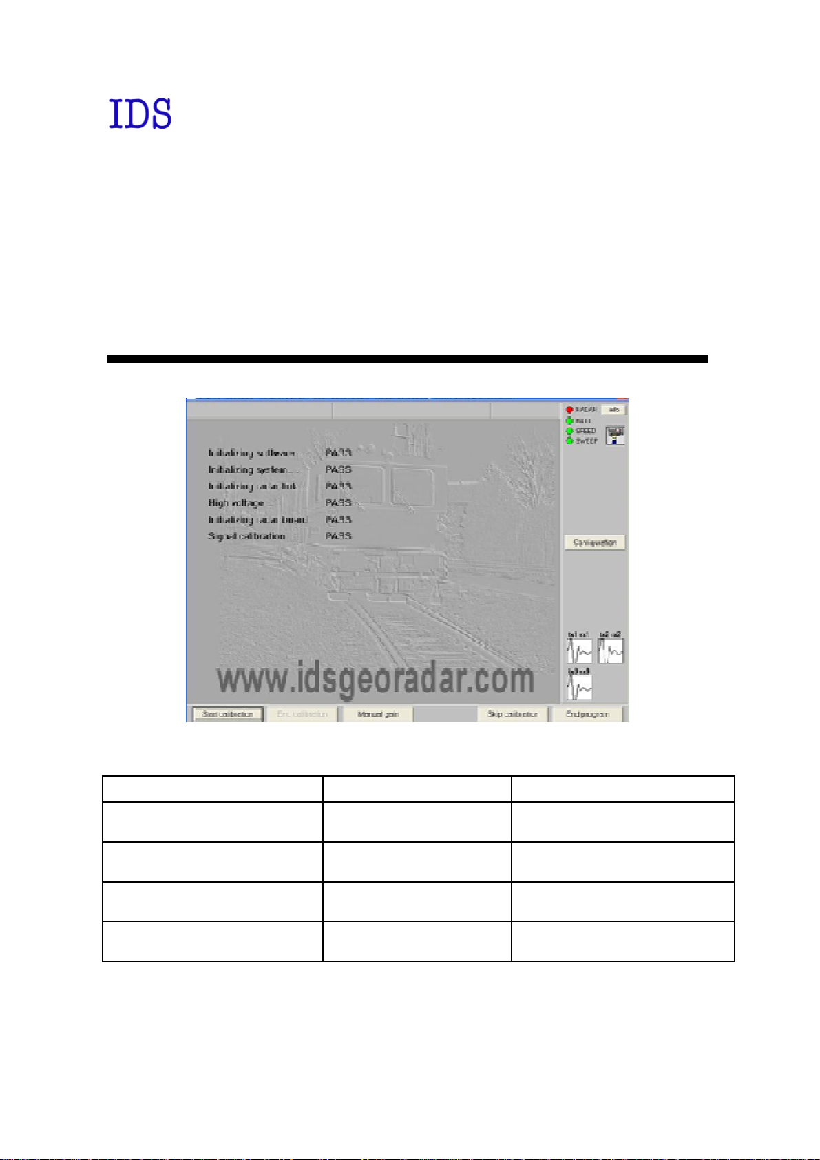
FIG. 4-1 – ACQUISITION SOFTWARE ICON ..............................................................33
FIG. 4-2 – SRS_PLUS ACQUISITION SOFTWARE STARTUP WINDOW................33
FIG. 4-3 – RADAR SELECTION WINDOW..................................................................34
FIG. 4-4 – RANGE FIELD ...............................................................................................34
FIG. 4-5 – SAM PLES PER SCAN....................................................................................35
FIG. 4-6 – PROPAGATION SPEED FIELD....................................................................35
FIG. 4-7 – GAIN CALIBRATION UNDERWAY...........................................................36
FIG. 4-8 – CONTROLLING THE PRESENCE OF RADAR SIGNAL ON THE
ANTENNA/S.............................................................................................................36
FIG. 4-9 –CALIBRATION FILE SELECTION WINDOW.............................................37
FIG. 4-10 – GAIN WINDOW...........................................................................................37
FIG. 4-11 – GAIN PARAM ETER SETTINGS WINDOW..............................................38
FIG. 4-12 – GRAPHICAL CONSTRUCTION OF THE GAIN CURVE ........................39
FIG. 4-13 – M ANUAL CONSTRUCTION OF THE GAIN CURVE..............................39
FIG. 4-14 – THE SYSTEM FUNCTION SPY LIGHTS..................................................40
FIG. 4-15 – INFO BUTTON.............................................................................................40
FIG. 4-16 – INFO WINDOW............................................................................................41
FIG. 4-17 – COLOUR PALETTES AVAILABLE...........................................................41
FIG. 4-18 – PROGRAM SHUT-DOWN WINDOW........................................................42
FIG. 4-19 – ACTIVATING THE ADVANCED SETTINGS M ENU..............................42
FIG. 4-20 –ADVANCED SETTINGS WINDOW............................................................43
FIG. 4-21 – ACQUISITION SELECTION WINDOW ....................................................44
FIG. 4-22 – NEW SURVEY WINDOW...........................................................................45
FIG. 4-23 – THE *.MIS FOLDER DIRECTORY............................................................45
FIG. 4-24 – NEW ACQUISITION TEXT BOX...............................................................45
FIG. 4-25 – SETTING UP A NEW ACQUISITION........................................................46
FIG. 4-26 – THE CASTLE.M IS FOLDER DIRECTORY...............................................46
FIG. 4-27 – NEW ACQUISITION WINDOW.................................................................47
FIG. 4-28 – ACQUISITION PARAM ETERS WINDOW................................................48
FIG. 4-29 – POS. M ARKER BUTTON............................................................................48
FIG. 4-30 – DIAGRAM SHOWING AN EXAM PLE OF HOW TO USE THE
FUNCTION “WITH 1ST M ARKER 1 STEP”.........................................................51
FIG. 4-31 – RADAR SECTION DURING ACQUISITION ............................................52
FIG. 4-32 – DATA SAVING WINDOW..........................................................................53
12 / 76

IDS Ingegneria Dei Sistemi S.p.A. Protocol: MN/2009/030 - Rev. 1.2
Safe Rail System Data Acquisition Software
FIG. 4-33 – ACQUISITION WINDOW ACTIVATED FOR PERFORMING
OPERATIONS IN REVIEW M ODE........................................................................54
FIG. 4-34 – ACQUISITION EDITING WINDOW..........................................................56
FIG. 4-35 – WINDOW FOR EDITING PARAM ETERS AFTER ACQUISITION
TRANSVERSAL.......................................................................................................56
FIG. 4-36 – SCANS FROM THE SAME ACQUISITION...............................................56
FIG. 4-37 – RENAM E ACQUISITION WINDOW.........................................................57
FIG. 4-38 – DELETE ACQUISITION WINDOW...........................................................57
FIG. 6-1 – MAIL SENT BY IDS TO THE CLIENT........................................................59
FIG. 6-2 – CLIENT DATA INSERTION FORM.............................................................60
FIG. 6-3 – WEBEX SET UP WINDOW...........................................................................60
FIG. 6-4 – WELCOM E TO WEBEX SUPPORT CENTER WINDOW..........................61
FIG. 6-5 – COMMAND ACCEPTANCE WINDOW ......................................................61
FIG. A. 1 - NO OBSTACLE MUST BE PRESENT BETWEEN BUFFERS ..................63
FIG. A. 2 - EXAMPLE OF A TYPICAL INSTALLATION OF THE SYSTEM ............63
FIG. A. 3 - OVERVIEW OF THE FIXING FRAM E.......................................................64
FIG. A. 4 - SPECIFICATIONS FOR THE CROSS-BARS AND THE BRACKETS......65
FIG. A. 5 - SPECIFICATIONS FOR THE VERTICAL-BARS.......................................65
FIG. B. 1 – SRS_PLUS CONTROL UNIT AND CF-30 NOTEBOOK...........................66
FIG. C. 1 - CONNECTING THE GPS TO THE NOTEBOOK COMPUTER.................68
FIG. C. 2 - EXTERNAL DEVICE SETTINGS COMMAND..........................................68
FIG. C. 3 - EXTERNAL DEVICE SETTINGS WINDOW..............................................69
FIG. C. 4 - EXTERNAL DEVICE SETTINGS FIELD....................................................69
FIG. C. 5 - COM SETTINGS WINDOW.........................................................................70
FIG. C. 6 - GPS SPY .........................................................................................................70
FIG. C. 7 - EXAMPLE OF A GPS FILE ..........................................................................71
FIG. D. 1 – VIDEOCAM ERA “LUM ENERA LM135C”................................................72
FIG. D. 2 - EXTERNAL DEVICE SETTINGS COMM AND..........................................73
FIG. D. 3 - EXTERNAL DEVICE SETTINGS WINDOW .............................................73
FIG. D. 4 – CAM ERA PROPERTIES..............................................................................74
FIG. D. 5 – CAM ERA VIEW WINDOW.........................................................................75
FIG. D. 6 – FOLDER “CAM ERA”...................................................................................75
13 / 76

IDS Ingegneria Dei Sistemi S.p.A. Protocol: MN/2009/030 - Rev. 1.2
Safe Rail System Data Acquisition Software
1. OVERVIEW
1.1 How to use this manual
This SRS_PLUS software user manual is subdivided as follows:
•
Chap. 1: Overview.
•
Chap. 2: Hardware configuration of the SRS_PLUS and of the SRSFW400 systems
•
Chap. 3: SRS_PLUS/SRS-FW400 acquisition software operating
procedures.
•
Chap. 4: Setup of the SRS_PLUS/SR S-FW400 acquisition software
•
Chap. 5: Error messages and warnings
•
Chap. 6: On Line Assistance
14 / 76
IDS Ingegneria Dei Sistemi S.p.A. Protocol: MN/2009/030 - Rev. 1.2
LAN port
Battery Port
Start up
Switched on
Battery
Notebook
Safe Rail System Data Acquisition Software
2. THE SRS SYSTEM HARDWARE CONFIGURATION
The SRS system consists of the following parts:
• SRS_PLUS or SRS-FW400 Control Unit
• Notebook Computer
• Lan Cable
• Battery Cable
• Battery Pack
• Power supply cable
• Position sensor
• From one to four 400MHz antennas
2.1 The SRS_PLUS Control Unit
The
SRS_PLUS Control Unit
antennas and digitalisin g the acquired radar data and it has the following ports:
• Lan Port
• Battery Port
• Wheel Port
for a network connection to the Notebook Computer
to connect the battery
to connect the position sensor wheel
is the control unit responsible for directing the
• Ant. 1 - Ant. 2 – Ant. 3 – Ant. 4
for the connections to the radar antennas
• Start up button and indicator light
• Voltmeter
• Notebook connection port
indicator light
Fig. 2-1 – View of Control Unit, start up side
Voltmeter
button
connection
port
15 / 76
IDS Ingegneria Dei Sistemi S.p.A. Protocol: MN/2009/030 - Rev. 1.2
Antenna 1, 2, 3, 4
Wheel Port
Safe Rail System Data Acquisition Software
Connectors
Fig. 2-2 – View of Control Unit, antenna connectors side
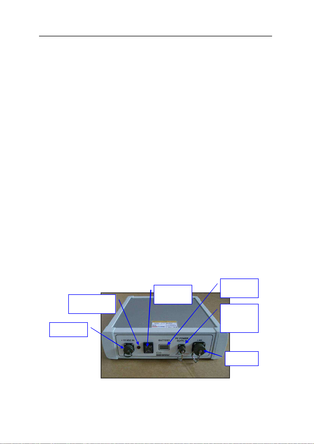
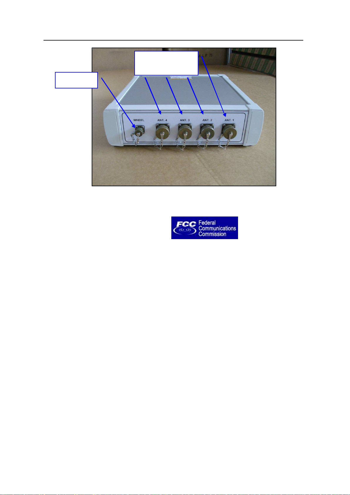
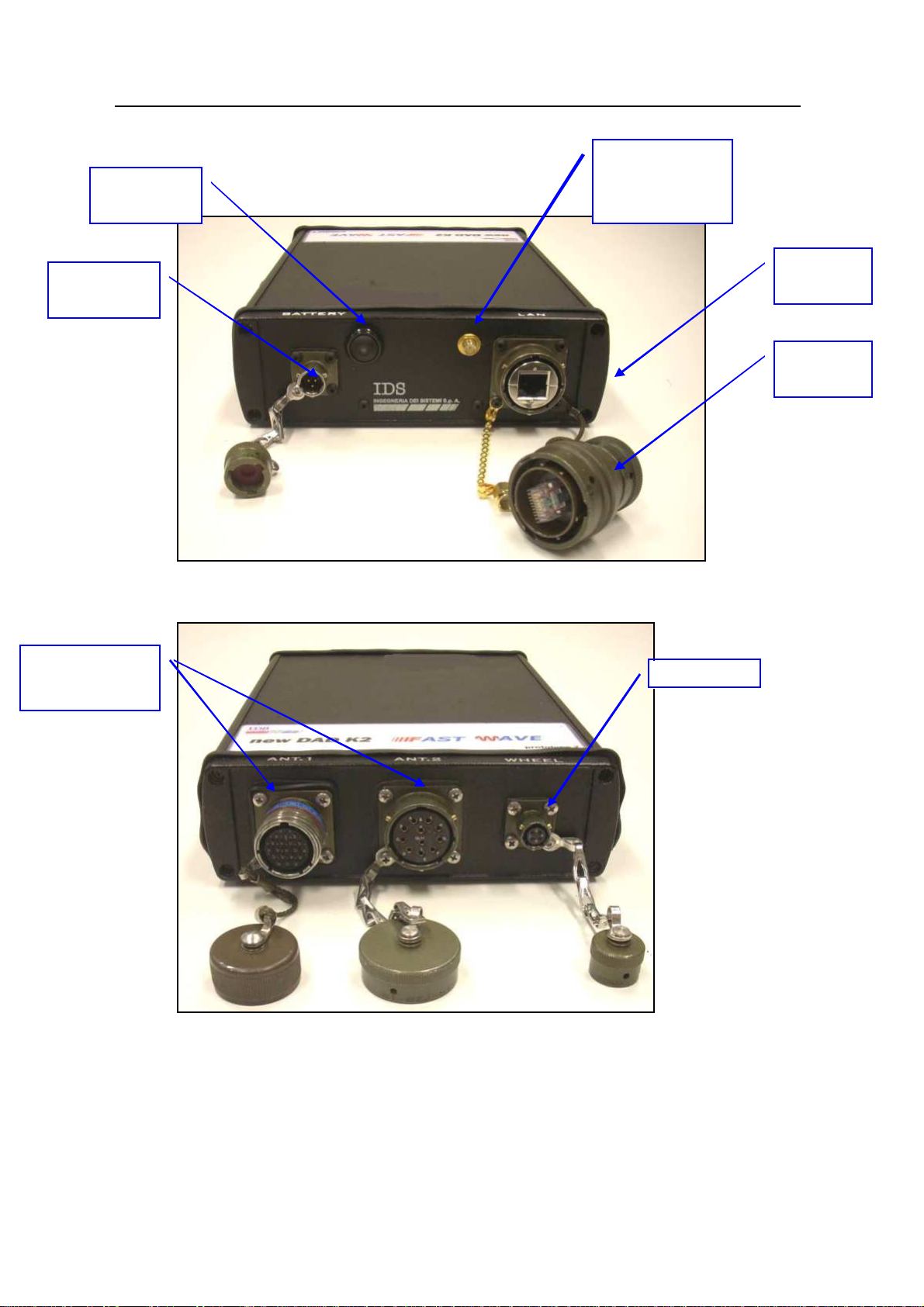
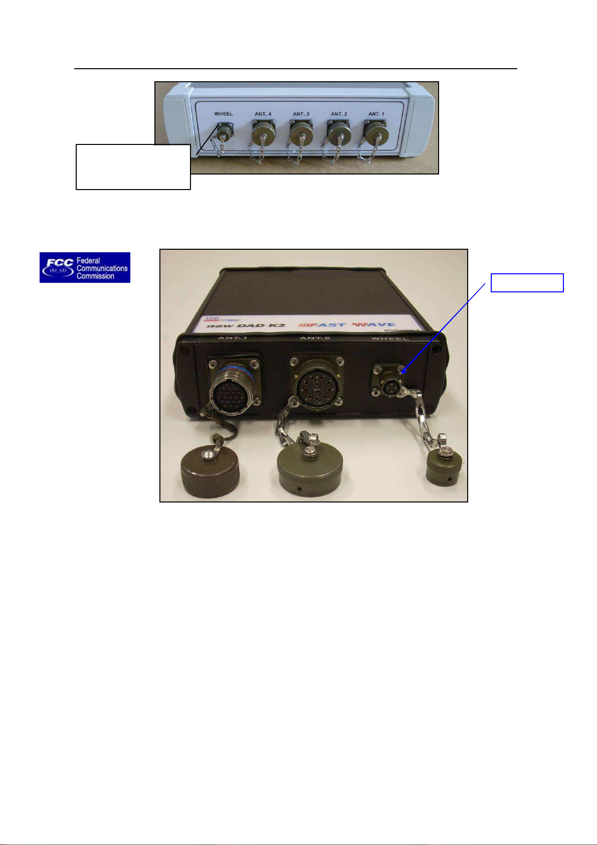
2.2 The SRS-FW400 Control Unit
The
SRS-FW400 Control Unit
• Lan Port
• Battery Port
• Wheel Port
for a network connection to the Notebook Computer
to connect the battery
to connect the position sensor wheel
• Ant.1/CHAIN - Ant.2
• Power switch with pilot light
• Wireless antenna connector
has the following ports
for radar antenna connection
16 / 76
IDS Ingegneria Dei Sistemi S.p.A. Protocol: MN/2009/030 - Rev. 1.2
Ant1 and Ant 2
Start up
Wireless
Wireless
Safe Rail System Data Acquisition Software
button
Battery Port
-
antenna
connector
Fig. 2-3 – SRS-FW400 Control unit front panel with Battery Port, Lan Port and
wireless connector
LAN port
plug
Connectors
Fig. 2-4-SRS-FW400 Control unit rear panel with connections to position sensor
and antennas
The SRS-FW400 uses the Ant.1 connector only (19 pins connector) to connect the
SRS antennas with a cascade connection.
17 / 76
IDS Ingegneria Dei Sistemi S.p.A. Protocol: MN/2009/030 - Rev. 1.2
For DAD
To connect the
Safe Rail System Data Acquisition Software
connection or
toward another
antenna
Fig. 2-5 – SRS antenna with a 19 pole connector and possibility of a cascade
connection
The Ant.2 connector (11 pins) is not used by the SRS-FW400 sy stem.
2.3 The Notebook Computer
The
SRS_PLUS
dedicated to the specific phases of setting up, acquiring and saving radar data.
acquisition SW is installed on a
Notebook Computer.
other antenna
This SW is
Fig. 2-6 – Panasonic Toughbook CF-30
18 / 76
IDS Ingegneria Dei Sistemi S.p.A. Protocol: MN/2009/030 - Rev. 1.2
NOTE
occur between their own software and any other software installed
y the user onto the Notebook Computer. IDS doesn’t guarantee
that equipment performance will be maintained using
Safe Rail System Data Acquisition Software
IDS recommends the use of the Panasonic model CF-30
Fig. 2-6
) which has the following characteristics:
•
Intel Duo Processor L2400
•
Processor speed: 1.66 GHz.
•
Ethernet 100 Mbit/sec card.
•
M inimum 512 M byte RAM
•
M onitor resolution (colour) 1024X768 (13.3”).
•
Operative system: Windows XP Professional.
•
HDD > 80 Gbyte, shock-mounted.
•
No communication software of the type Firewall, WiFi or Antivirus
protection may be installed on the computer; these types of SW enter into
conflict with the SRS_PLUS acquisition SW
•
Touch screen.
•
Water-proof (>= IP54).
Notebook Computer,
(see
IDS takes no responsibility for any functional conflicts that may
!
2.4 Connecting the Control Unit - Notebook Computer
The following describes how to cable the Control Unit to the Notebook
Computer
•
Use the
Notebook Computer
b
configurations different to those recommended.
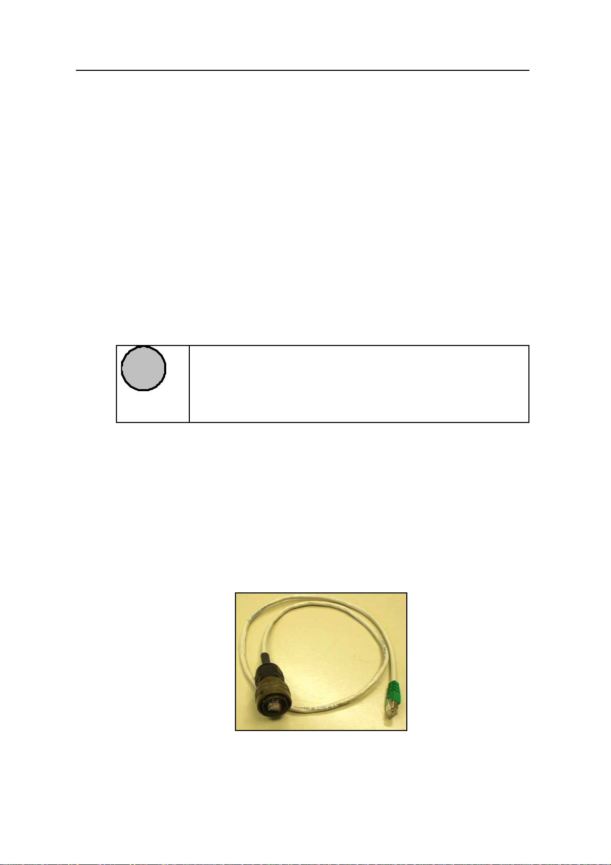
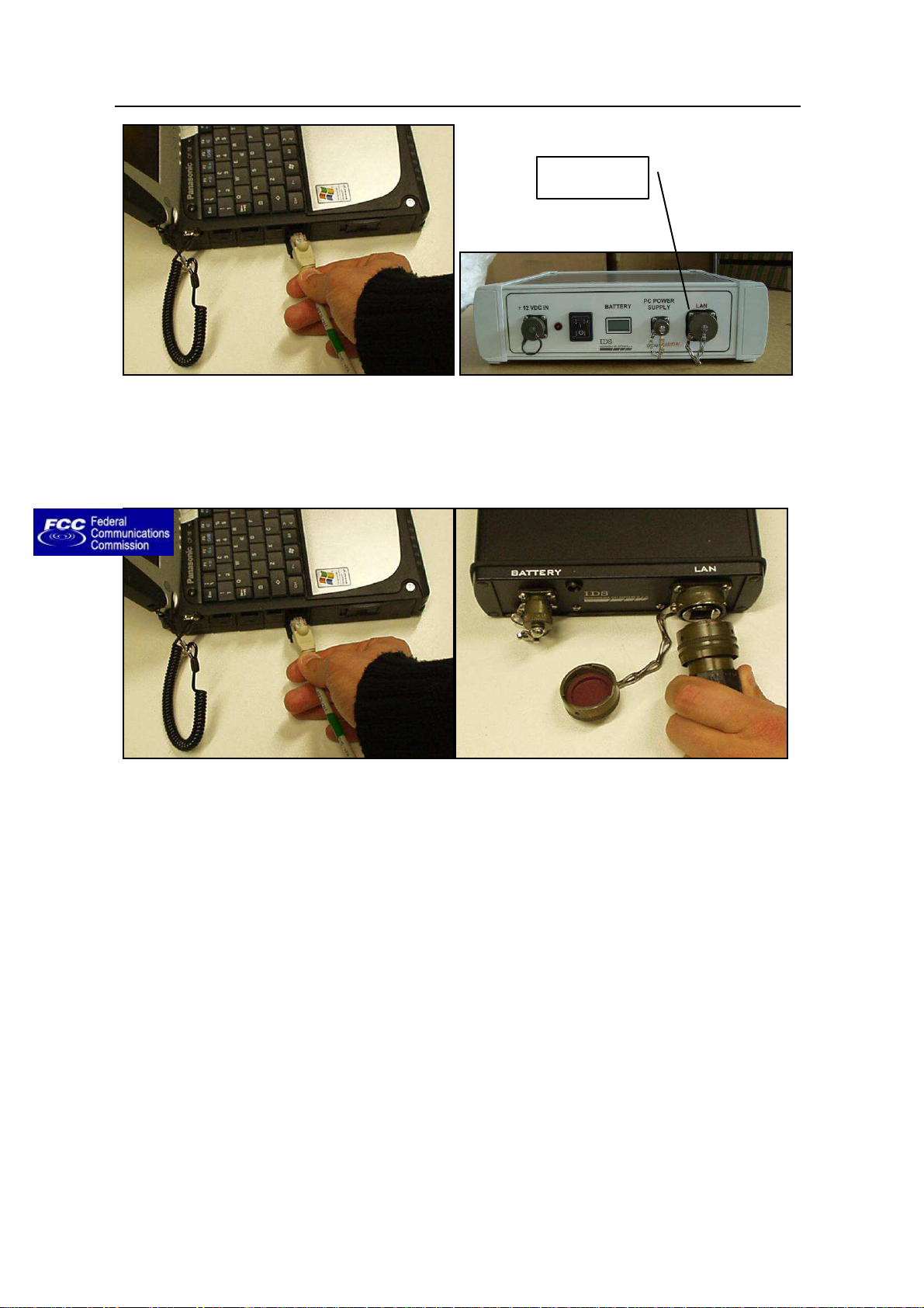
Lan Cable
(Fig. 2-7) to connect the
as shown in (Fig. 2-8)
Control Unit
and the
Fig. 2-7 – Lan Cable
19 / 76
IDS Ingegneria Dei Sistemi S.p.A. Protocol: MN/2009/030 - Rev. 1.2
Safe Rail System Data Acquisition Software
Lan port
Fig. 2-8 – Lan Cable connection between the Notebook Computer and the Control
Unit (SRS_PLUS)
Fig. 2-9 – Lan Cable connection between the Notebook Computer and the Control
Unit (SRS-FW400 only)
•
Connect the
2-10) as shown in (Fig. 2-11). Then connect the black and the red clamps
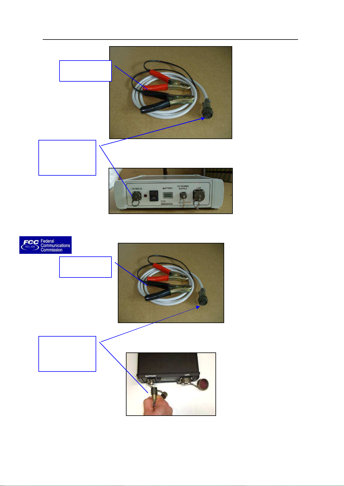
respectively to the negative and to the positive electrode of a Car Battery
(12V). The Voltmeter will automatically measure the battery voltage.
Control Unit
to the
Battery
using the
Battery Cable
(Fig.
20 / 76
IDS Ingegneria Dei Sistemi S.p.A. Protocol: MN/2009/030 - Rev. 1.2
Connect the
Red and black
Connect the
Red and black
Safe Rail System Data Acquisition Software
clamps
battery cable to
corresponding
Control Unit port
Fig. 2-11 – Connecting the Control Unit to the battery (SRS_PLUS)
clamps
Fig. 2-10 – Battery Cable
battery cable to
corresponding
Control Unit port
Fig. 2-13 – Connecting the Control Unit to the battery (SRS-FW400 only)
Fig. 2-12 – Battery Cable
21 / 76
IDS Ingegneria Dei Sistemi S.p.A. Protocol: MN/2009/030 - Rev. 1.2
PC Power
DOPPLER
CONNECTION
WHEEL PORT
POWER PORT
DOPPLER
CONNECTION
DOPPLER PORT
Safe Rail System Data Acquisition Software
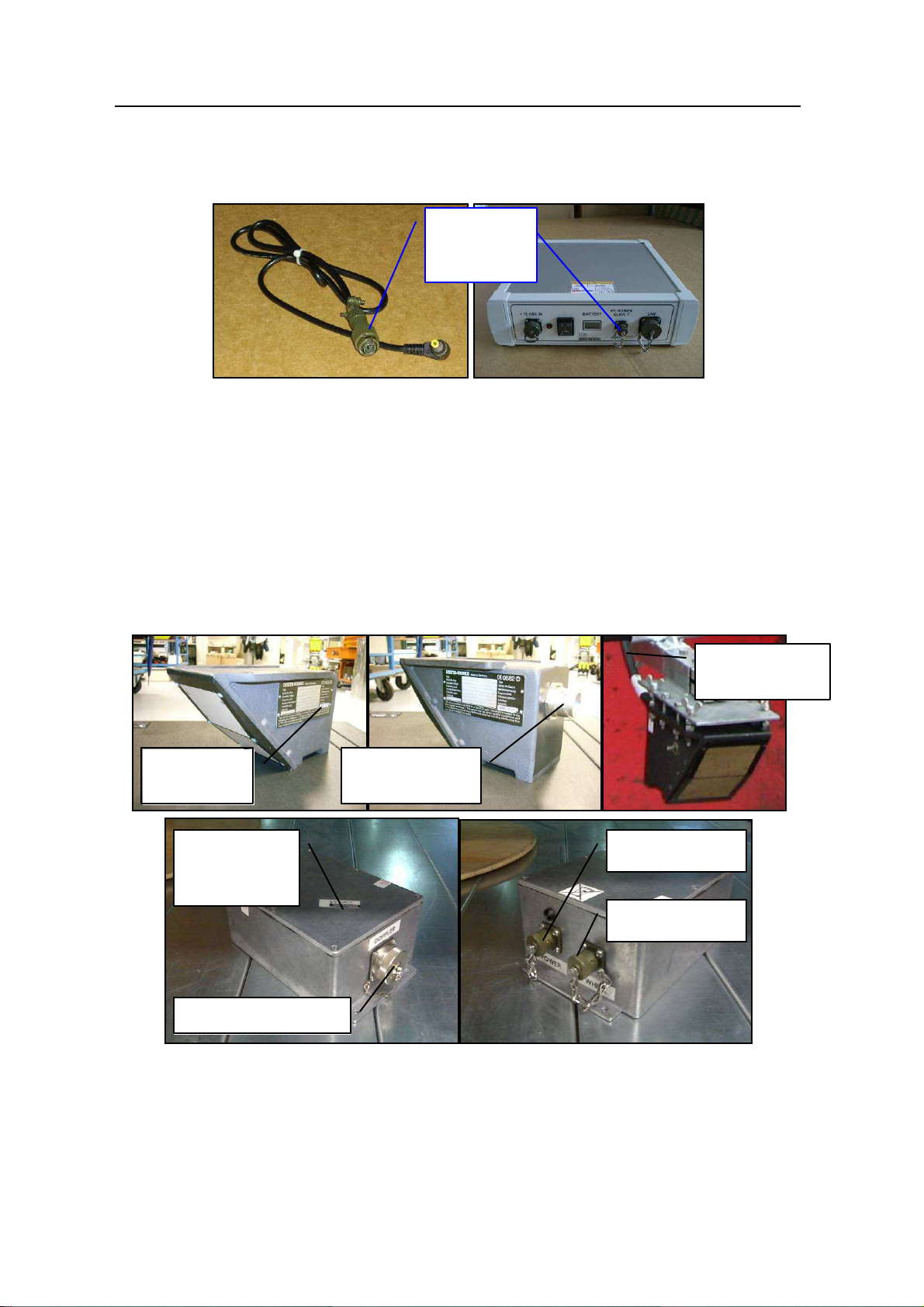
• SRS_PLUS only: Then connect the power supply cable to the PC POWER
SUPPLY port on the Control Unit and to the Notebook PC (see Fig. 2-14).
Supply
connection
Fig. 2-14 – Power supply cable and connection to the Control Unit
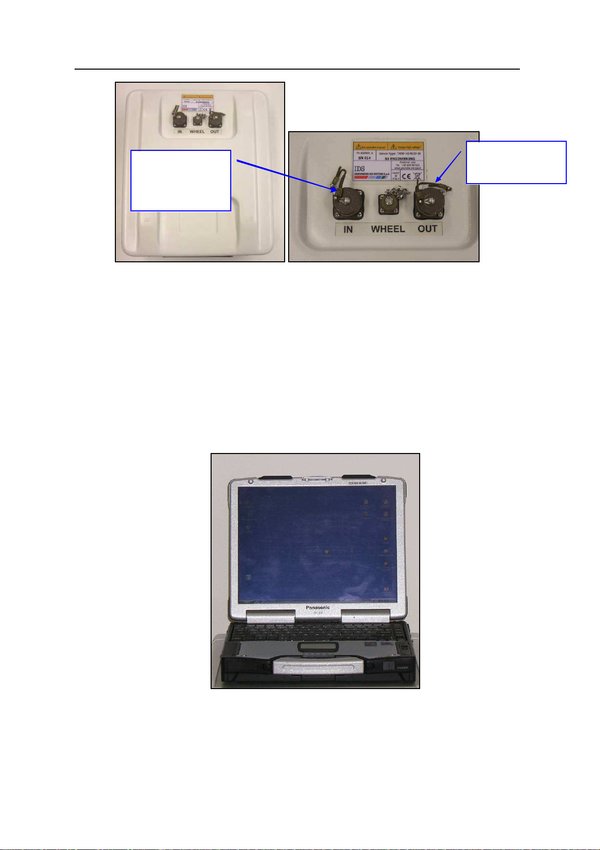
2.5 Position radar sensor
As position sensor we provide a Deuta-Werke DRS05 Doppler system (see Fig. 2-15).
The Doppler system must be connected through its cable to the Doppler interface box
(Doppler port). Then you have to connect the wheel cable from the Doppler interface box
(wheel port) to the DAD CONTROL UNIT wheel port.
CABLE
SYSTEM
INTERFACE
BOX
PORT
Fig. 2-15 – Position sensor
22 / 76
IDS Ingegneria Dei Sistemi S.p.A. Protocol: MN/2009/030 - Rev. 1.2
WHEEL PORT ON
Wheel Port
Safe Rail System Data Acquisition Software
THE DAD
CONTROL UNIT
Fig. 2-16 – Wheel port on the SRS_PLUS control unit
Fig. 2-17 – Wheel port on the SRS-FW400 control unit
23 / 76
 Loading...