

IDS GeoRadar s r l IBIS SU User Manual

- PRO/010/M1 Rev 4 -
INGEGNERIA DEI SISTEMI S.p.A.
R
ev. 1.1
N°doc: MN/2009/071
Config.: IBIS-S-PRCS-OUT-MN
IBIS-S System
IMAGE BY INTERFEROMETRIC SURVEY
IBIS-S v. 1.0 -
User Manual
Pisa, June 2010
Tot. N° pages = 48

IDS Ingegneria Dei Sistemi S.p.A. N doc: MN/2009/071 - Rev. 1.1
(see
IBIS-S v. 1.0 - User Manual
Config.: IBIS-S-PRCS-OUT-MN
KEY WORDS
IBIS-S, INTERFEROMETER, INSTALLATION
SUMMARY
IBIS-S system user manual. This document illustrates the contents of
the package and the procedures the operator must perform to set up and
dismantle the IBIS-S system.
Document Evolution
Revision Date Reason for change
Rev. 1.0 October 2009 First Edition with Battery information (according to DL 188
dated 20/11/2008)
Rev. 1.1 June 2010 Document revision for declarations for US and Canada
RNC 201005097)
Document change record
RNC References Change description
201005097 Before index Declarations for US and Canadian customers
HW and SW versions covered by this document
IBIS-S apparatus v. 1.0.
Warnings
IDS will not be held responsible for the consequences of an improper use of the equipment.
IDS will not be held responsible for the consequences of an improper use of the software
All information contained in this document is property of IDS.
2 / 48
All information contained in this document is property of IDS. All rights reserved.

IDS Ingegneria Dei Sistemi S.p.A. N doc: MN/2009/071 - Rev. 1.1
IBIS-S v. 1.0 - User Manual
Config.: IBIS-S-PRCS-OUT-MN
Contacts
IDS Ingegneria Dei Sistemi S.p.A.
Via Sterpulino, 20
56121 PISA (Loc. Ospedaletto)
Tel: +3905096711
Fax: +39050961721
All information contained in this document is property of IDS. All rights reserved.
3 / 48

IDS Ingegneria Dei Sistemi S.p.A. N doc: MN/2009/071 - Rev. 1.1
OR THE CONSEQUENCES
OR THE
ACCURACY OF
E TOOLS, THEY MUST
LLIGENT
ED AS AN
RELY ON THE
PLETE
SUMES NO LIABILITY FOR
ANY DIRECT, INDIRECT, SPECIAL, INCIDENTAL OR
CONSEQUENTIAL DAMAGES OR INJURIES CAUSED BY SUCH
RELIANCE ON THE ACCURACY, RELIABILITY, OR TIMELESS OF
ON
OBTAINED FROM THE AUTOMATED DATA
, DOES SO AT HIS OR HER
IBIS-S v. 1.0 - User Manual
Config.: IBIS-S-PRCS-OUT-MN
DISCLAIMER
IDS WILL NOT BE HELD RESPONSIBLE F
OF AN IMPROPER USE OF THE EQUIPMENT AND/
SOFTWARE.
THIS SOFTWARE MAY INCLUDE AUTOMATED DATA
PROCESSING AND ANALYSIS TOOLS.
WHILE EVERY EFFORT IS MADE TO ENSURE THE
THE INFORMATION PROVIDED BY THOS
NOT BE INTENDED AS A SUBSTITUTE FOR INTE
ANALYSIS; RATHER, THEY HAVE TO BE INTEND
ADVISOR AND THE USER MUST NOT COMPLETELY
RESULTS PROVIDED BY THEM TO GIVE THE COM
ANSWER.
IDS INGEGNERIA DEI SISTEMI SPA AS
THE INFORMATION PROVIDED BY THOSE TOOLS.
ANY PERSON OR ENTITY WHO RELIES ON INFORMATI
PROCESSING/ANALYSIS TOOLS ONLY
OWN RISK.
All information contained in this document is property of IDS. All rights reserved.
4 / 48
IDS Ingegneria Dei Sistemi S.p.A. N doc: MN/2009/071 - Rev. 1.1
IBIS-S v. 1.0 - User Manual
Config.: IBIS-S-PRCS-OUT-MN
SAFETY INFORMATION
All information contained in this document is property of IDS. All rights reserved.
5 / 48
IDS Ingegneria Dei Sistemi S.p.A. N doc: MN/2009/071 - Rev. 1.1
Warning: this equipment is destined for use in industrial environments
light industry
environments, this apparatus may generate radio interference: in this case,
the user may be required to operate while taking appropriate
The apparatus is sensitive to the presence of external electromagnetic fields,
IBIS-S v. 1.0 - User Manual
Config.: IBIS-S-PRCS-OUT-MN
(Class A apparatus). In residential, commercial and
countermeasures.
which may reduce its performance.
All information contained in this document is property of IDS. All rights reserved.
6 / 48

IDS Ingegneria Dei Sistemi S.p.A. N doc: MN/2009/071 - Rev. 1.1
IBIS-S v. 1.0 - User Manual
Config.: IBIS-S-PRCS-OUT-MN
IMPORTANT NOTE FOR THE US CUSTOMERS
Model No.: IBIS-KU
FCC ID: UFW-IBIS-KU
This device complies with part 90 of the FCC Rules.
Caution: Any changes or modifications to this device not explicitly approved by manufacturer could void your
authority to operate this equipment.
This equipment complies with FCC radiation exposure limits set forth for an uncontrolled environment. This
equipment should be installed and operated with minimum 20 cm between the radiator and your body. This
transmitter must not be collocated or operating in conjunction with any other antenna or transmitter unless
authorized to do so by the FCC.
IMPORTANT NOTE FOR THE CANADIAN CUSTOMERS
Model No.: IBIS-KU
IC ID: 8991A-IBISKU
This device has been designed to operate with the antennas listed below, and having a maximum gain of 22 dB.
Antennas not included in this list or having a gain greater than 22 dB are strictly prohibited for use with this device.
The required antenna impedance is 50 ohms.
IBIS-ANT1-H38V18
IBIS-ANT2-H29V25
IBIS-ANT3-H17V15
IBIS-ANT4-H11V10
IBIS-ANT5-H12V39
IBIS-ANT6-H51V20
Operation is subject to the following two conditions: (1) this device may not cause interference, and (2) this device
must accept any interference, including interference that may cause undesired operation of the device.
To reduce potential radio interference to other users, the antenna type and its gain should be so chosen that the
equivalent isotropically radiated power (e.i.r.p.) is not more than that permitted for successful communication.
All information contained in this document is property of IDS. All rights reserved.
7 / 48

IDS Ingegneria Dei Sistemi S.p.A. N doc: MN/2009/071 - Rev. 1.1
Before cleaning any external parts of the apparatus, make sure
that all cables have been disconnected, including the power
used, make sure it is not too wet,
to avoid any damage to the electrical components of the
equipment. Wait until the equipment is totally dry before
Do not apply liquid directly to the electrical contacts of the
If a specific spray is used to clean the PC
n any case, do not
spray it onto the cleaning
IBIS-S v. 1.0 - User Manual
Config.: IBIS-S-PRCS-OUT-MN
!
WARNING
CLEANING INFORMATION
supply cable. If a damp cloth is
reconnecting the cables.
The IBIS-S should be cleaned periodically using a damp cloth.
Do not use solvents or abrasive detergents.
various connectors.
TFT monitor, make sure it is not flammable; i
spray it directly on the screen, instead,
cloth.
All information contained in this document is property of IDS. All rights reserved.
8 / 48
IDS Ingegneria Dei Sistemi S.p.A. N doc: MN/2009/071 - Rev. 1.1
NOTE
IBIS-S v. 1.0 - User Manual
Config.: IBIS-S-PRCS-OUT-MN
BATTERIES REMOVAL INFORMATION
: Batteries must be recycled according to national regulations. Read
carefully the warnings and information on the batteries.
Laptop Batteries
:
Manufacturer: PANASONIC
Type: Li-ion Ni
Characteristics: 10.65V 5.7Ah
Removal instructions:
1. turn off the laptop;
2. open the drawer marked with the battery symbol;
3. extract the battery pack by pulling the tab.
Radar batteries
:
Manufacturer: FIAMM FG21202
Type: rechargeable lead acid, non
spillable batteries
Characteristics: 12V & 12Ah
Removal instructions:
1. disconnect the battery from the instrument:
a. pull the connector wings;
b. separate the connectors;
2. remove the battery from the cover (optional) by opening
the strap.
All information contained in this document is property of IDS. All rights reserved.
9 / 48

IDS Ingegneria Dei Sistemi S.p.A. N doc: MN/2009/071 - Rev. 1.1
IBIS-S v. 1.0 - User Manual
Config.: IBIS-S-PRCS-OUT-MN
RECICLYING
The crossed out wheeled bin symbol shown on the equipment indicates that
the product must be recycled separately from other waste at the end of its
useful life.
Separate waste disposal of this product at the end of its useful life will be
organised and managed by IDS. When you decide to dispose of the
equipment, contact IDS and follow the system that IDS has set up to permit
the separate collection of the apparatus at its life end.
Adequate separate collection for its subsequent recycling, treatment and
environmental friendly disposal contribute towards avoiding any
unnecessary effects on the environment and to health and favour the reuse or
recycling of the materials that make up the equipment. Unauthorised disposal
of this product as unsorted waste by its possessor will lead to an
administrative penalty foreseen by national regulations.
All information contained in this document is property of IDS. All rights reserved.
10 / 48

IDS Ingegneria Dei Sistemi S.p.A. N doc: MN/2009/071 - Rev. 1.1
IBIS-S v. 1.0 - User Manual
Config.: IBIS-S-PRCS-OUT-MN
WARRANTY CERTIFICATE CONDITIONS
1) IDS Ingegneria dei Sistemi S.p.A, hereinafter referred to as IDS, warrants hardware/software
products for a period of 12 months from the delivery date to the original customer;
2) The delivery date is certified by the “Warranty Registration Form”;
3) IDS’s hardware products will be free from defects in materials workmanship under normal use and
service;
4) IDS’s obligation is limited to repairing or replacing parts or equipment which are returned to IDS,
without alteration or further damage, and which in IDS s judgment, were defective or became
defective during normal use;
5) IDS’ software will have to be installed on a PC according to the requirement of the IDS hardware (
see IDS User’s Guide the Software Data Acquisition);
6) IDS’ s software products designed by IDS for use for IDS hardware products are warranted not to
fail to execute their programming instructions due to defects during the warranty period, provided
they are properly installed on IDS hardware products. IDS does not warrant if the IDS software will
be used and operated in hardware and software combinations not selected by IDS;
7) IDS does not assumes any liability for any direct, indirect, special, incidental or consequential
damages or injuries caused by proper or improper operation of its equipment whether defective or
not defective;
8) This software may include automated data processing and analysis tools. While every effort is made
to ensure the accuracy of the information provided by those tools, they must not be intended as a
substitute for intelligent analysis; rather, they have to be intended as an advisor and the user must
not completely rely on the results provided by them to give the complete answer. IDS assumes no
liability for any direct, indirect special, incidental or consequential damages or injuries caused by
such reliance on the accuracy, reliability, or timeliness of the information provided by those tools.
Any person or entity who relies on information obtained from the automated data
processing/analysis tools only, does so at his or her own risk;
9) IDS’s warranty does not extend and shall not apply to:
a) Products which have been repaired or altered by other than IDS personnel;
b) Products which have been subjected to misuse, neglect, accident or improper installation;
c) Products in which have been installed Hardware/Software accessories not supplied by IDS
and/or without any approval by IDS;
d) Products which have been connected to equipment different from the ones supplied by IDS
(except the PC data Logger which must conform to IDS specifications;
e) Products which have been damaged by natural disaster or calamities.
10) Before returning any equipment to IDS , you have to contact the IDS Customer Care Office that will
authorize you to return the material to be repaired;
11) Once the parts/equipment to be repaired arrive to IDS, IDS may inspect the defective products to
verify they are eligible for repair or replacement. All packing must be saved for inspection purpose
in order to assist IDS to understand the cause of the defects. IDS, will not be obliged to repair, or
replace for products returned as defective but damaged from abuse, misuse, negligence , accident
loss or damage in transit;
12) The final clients, is responsible for ensuring the defective products returned to be properly
packaged;
13) The above warranty are sole and exclusive, and no other warranty, whether written or oral, is
expressed or implied.
All information contained in this document is property of IDS. All rights reserved.
11 / 48

IDS Ingegneria Dei Sistemi S.p.A. N doc: MN/2009/071 - Rev. 1.1
IBIS-S v. 1.0 - User Manual
Config.: IBIS-S-PRCS-OUT-MN
INDEX
1. Introduction........................................................................................................................... 15
1.1 Scope.............................................................................................................................. 15
1.2 Field of application........................................................................................................15
1.3 Authorisation for use – national restriction.................................................................. 15
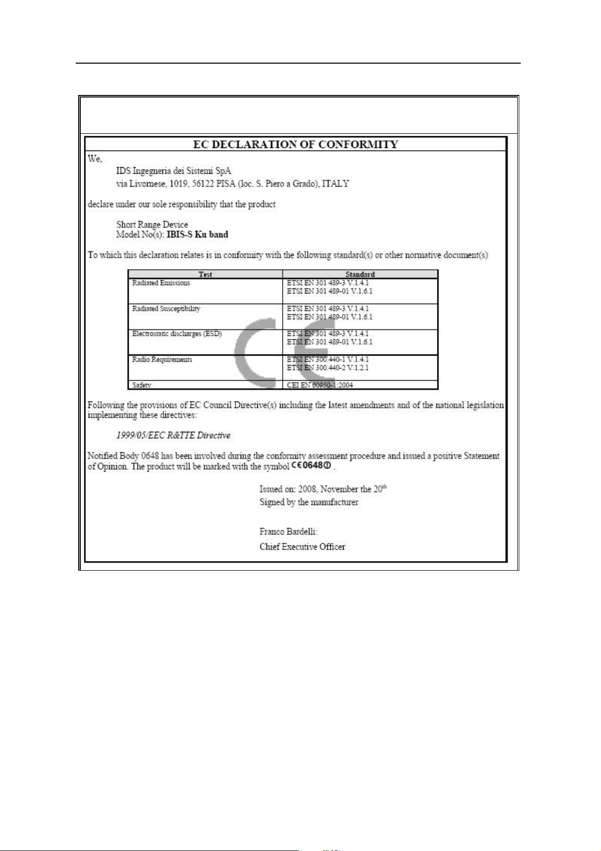
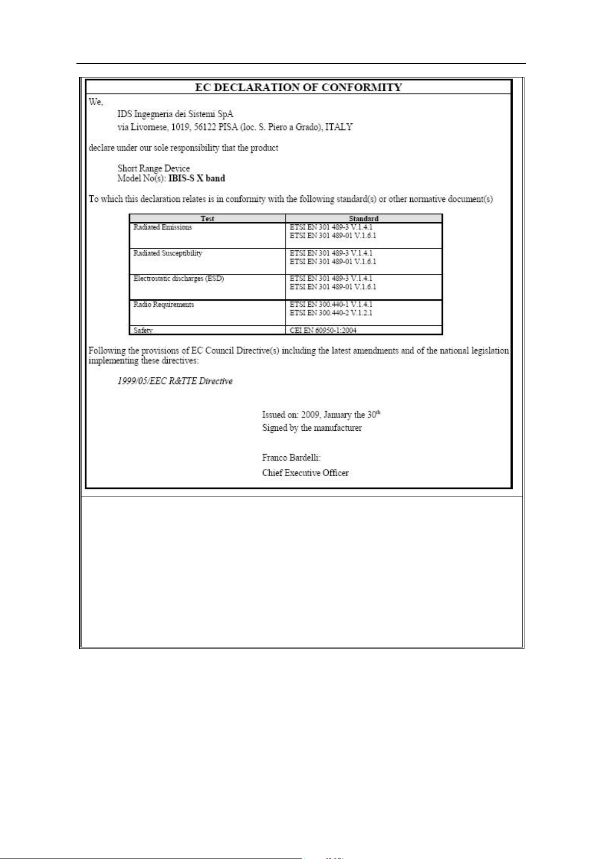
1.4 CE Marking ................................................................................................................... 16
1.5 Acronyms....................................................................................................................... 16
2. Overview.................................................................................................................................17
2.1 How to use this manual..................................................................................................17
2.2 General description of the IBIS-S system...................................................................... 17
3. Pack contents......................................................................................................................... 19
4. IBIS-S system hardware configuration............................................................................... 23
4.1 IBIS-S Sensor.................................................................................................................23
4.2 Antennas ........................................................................................................................ 24
4.2.1 Ku band system antennas ...............................................................................................24
4.2.2 X band system antennas .................................................................................................27
4.3 Control and acquisition PC...........................................................................................28
4.4 Batteries......................................................................................................................... 29
4.5 Connection cable kit IBIS-CS KIT................................................................................. 29
4.6 Tripod and three axial head .......................................................................................... 30
5. IBIS-S Installation and Dismantling Procedure................................................................. 31
5.1 Material required...........................................................................................................31
5.2 IBIS-S installation.......................................................................................................... 33
5.3 Dismantling IBIS-S........................................................................................................ 41
6. Useful Tips..............................................................................................................................43
6.1 Installation..................................................................................................................... 43
6.2 Use................................................................................................................................. 44
Appendix A - Restrictions......................................................................................................... 45
Appendix B - Technical Specifications.................................................................................... 45
B.1 - Radar sensor............................................................................................................... 45
B.2 - Batteries / battery charger..........................................................................................46
B.3 - Panasonic CF-19 PC.................................................................................................. 46
Appendix C - Elements of Radar Technology........................................................................ 47
C.1 - Definitions ..................................................................................................................47
C.1.1 Main antenna lobe .........................................................................................................47
All information contained in this document is property of IDS. All rights reserved.
12 / 48

IDS Ingegneria Dei Sistemi S.p.A. N doc: MN/2009/071 - Rev. 1.1
IBIS-S v. 1.0 - User Manual
Config.: IBIS-S-PRCS-OUT-MN
FIGURES INDEX
FIG. 2.1 – IBIS-S..........................................................................................................................................18
FIG. 3.1 – TRIPOD BAG .............................................................................................................................19
FIG. 3.2 – IBIS-S CASE...............................................................................................................................20
FIG. 4.1 – IBIS-S SENSOR..........................................................................................................................23
FIG. 4.2 – REAR (A) AND FRONT (B) VIEW OF IBIS-S SENSOR ........................................................24
FIG. 4.3 – BOTTOM VIEW IBIS-S SENSOR.............................................................................................24
FIG. 4.4 – IBIS-H20 VERTICAL PLANE PATTERN................................................................................25
FIG. 4.5 – IBIS-H20 HORIZONTAL PLANE PATTERN..........................................................................25
FIG. 4.6 – IBIS-H20 ANTENNA .................................................................................................................25
FIG. 4.7 – IBIS-H23 VERTICAL PLANE PATTERN................................................................................26
FIG. 4.8 – IBIS-H15 HORIZONTAL PLANE PATTERN..........................................................................26
FIG. 4.9 – IBIS-H15 VERTICAL PLANE PATTERN................................................................................26
FIG. 4.10 – IBIS-H15 HORIZONTAL PLANE PATTERN........................................................................26
FIG. 4.11 – IBIS-H13 VERTICAL PLANE PATTERN..............................................................................26
FIG. 4.12 – IBIS-H13 HORIZONTAL PLANE PATTERN........................................................................26
FIG. 4.13 – X BAND ANTENNA VERTICAL PLANE PATTERN ..........................................................27
FIG. 4.14 – X BAND ANTENNA HORIZONTAL PLANE PATTERN ....................................................27
FIG. 4.15 – PC PANASONIC CF-19...........................................................................................................28
FIG. 4.16 – CONNECTIONS SCHEME......................................................................................................29
FIG. 5.1 – THE IBIS-S CASE......................................................................................................................31
FIG. 5.2 – CONTENTS OF THE IBIS-S CASE..........................................................................................32
FIG. 5.3 – SECOND LAYER OF IBIS-S CASE CONTENTS....................................................................32
FIG. 5.4 – INSTALLED TRIPOD................................................................................................................33
FIG. 5.5 – COMPOSITION OF THE TRIAXIAL HEAD...........................................................................34
FIG. 5.6 – MOUNTED TRIAXIAL HEAD.................................................................................................34
FIG. 5.7 – TRIAXIAL HEAD FIXED TO THE TRIPOD...........................................................................35
FIG. 5.8 – UNBLOCKING THE LEVERS OF THE QUICK LOCK MECHANISM.................................35
FIG. 5.9 – METALLIC NUT........................................................................................................................36
FIG. 5.10 – TIGHTENING NUT .................................................................................................................36
FIG. 5.11 – SENSOR INSTALLATION ONTO THE TRIPOD..................................................................37
FIG. 5.12 – MOUNTING THE OPTICAL TELESCOPE............................................................................37
FIG. 5.13 – MOUNTING THE ANTENNAS..............................................................................................38
FIG. 5.14 – POINTING THE SENSOR.......................................................................................................38
FIG. 5.15 – REMOVE THE PROTECTION CAPS.....................................................................................39
FIG. 5.16 – CONNECTING THE SENSOR TO THE BATTERY..............................................................39
FIG. 5.17 – INSTALLED IBIS-S SYSTEM ................................................................................................40
FIG. 5.18 – START UP WINDOW OF THE IBIS-S CONTROLLER SOFTWARE .................................40
All information contained in this document is property of IDS. All rights reserved.
13 / 48

IDS Ingegneria Dei Sistemi S.p.A. N doc: MN/2009/071 - Rev. 1.1
IBIS-S v. 1.0 - User Manual
Config.: IBIS-S-PRCS-OUT-MN
FIG. 5.19 – REMOVING THE SENSOR FROM THE THREE AXIAL HEAD ........................................41
FIG. 5.20 – POSITION OF THE BODY OF THE THREE AXIAL HEAD WHEN PACKING IT AWAY42
FIG. 6.1 – PROJECTION OF DISPLACEMENT DATA............................................................................43
FIG. 6.2 – TRIPOD.......................................................................................................................................44
FIG. C. 1 – SCHEMATIC DIAGRAM OF THE ANTENNA BEAM.........................................................47
FIG. C. 2 – AREA OF THE SCENARIO COVERED BY THE ANTENNA BEAM MAIN LOBE ..........48
TABLES INDEX
TAB. 3.1 – TRIPOD BAG CONTENTS......................................................................................................19
TAB. 3.2 – IBIS-S CASE CONTENT..........................................................................................................22
TAB. 4-1 – WIDTH OF THE MAIN LOBES OF THE IBIS-H20 ANTENNAS AT -3 DB AND -10 DB.25
TAB. 4-2 – KU BAND ANTENNAS CHARACTERISTICS .....................................................................27
TAB. 4-3 – WIDTH OF THE MAIN LOBES OF THE X BAND ANTENNAS AT -3 DB AND -10 DB.27
All information contained in this document is property of IDS. All rights reserved.
14 / 48

IDS Ingegneria Dei Sistemi S.p.A. N doc: MN/2009/071 - Rev. 1.1
IBIS-S v. 1.0 - User Manual
Config.: IBIS-S-PRCS-OUT-MN
1. INTRODUCTION
This document provides an introduction to the IBIS-S system (Image By Interferometric
Survey-S), with particular reference to the concepts the user must learn before starting to
use this device. Therefore we recommend that you read the entire document before
starting the system.
If technical assistance is required, please use the contact numbers provided on page 3 of
this manual.
1.1 Scope
This document will provide the operator with all the necessary knowledge to install and
maintain the IBIS-L system. In particular, the manual describes:
- The contents of the cases;
- The procedure for installing and dismantling the system;
- Information for the safe use of the system.
1.2 Field of application
This document applies to the installation and dismantling of the of the IBIS system in S
configuration and its use in the field for monitoring quasi static or dynamic phenomena.
1.3 Authorisation for use – national restriction
European countries
IBIS-S system has been classified by the CEPT Administrations as SRD – Short Range
Device - i.e. a device that doesn’t cause interference to other systems operating in the
same frequency band. IBIS-S has so been included in the ERC/REC 70-03 which defines
the SRD equipment.
For Ku band system
While the European countries update their national frequency allocation table applying the
new recommendations, currently the use of IBIS-S system outside a laboratory can still be
subject to authorisation by the Competent Ministry of the country where the system will
be used. Please refer to the country’s Competent Ministry to know whether there is the
need of an authorisation.
For X band system
Almost all the European countries have applied the ERC/REC 70-03 for the X band
system. Please refer to the Competent Ministry of the country where the system will be
used to know if there are limitations in the use of X band IBIS-S equipment.
All information contained in this document is property of IDS. All rights reserved.
15 / 48
 Loading...