

IDS GeoRadar s r l IBIS KU ETH User Manual

MNG/2017/0016
Rev 1.0
IBIS-ArcSAR
User manual

INDEX
INDEX
1 INTRODUCTION .............................................................................................................................................................................................................................. 5
1.1 Purpose ....................................................................................................................................................................................................................... 5
1.2 Application field .......................................................................................................................................................................................................... 5
2 ABOUT THE MANUAL ..................................................................................................................................................................................................................... 6
2.1 Manual layout ............................................................................................................................................................................................................. 6
2.2 Symbols ....................................................................................................................................................................................................................... 6
2.3 Glossary and acronyms ............................................................................................................................................................................................... 7
2.4 Reference .................................................................................................................................................................................................................... 7
3 GENERAL DESCRIPTION .................................................................................................................................................................................................................. 8
4 IBIS-ArcSAR HARDWARE BREAKDOWN ........................................................................................................................................................................................ 11
4.1 ArcSAR Trailer ........................................................................................................................................................................................................... 11
4.2 ArcSAR Acquisition Unit ............................................................................................................................................................................................ 11
4.3 ArcSAR Supply Unit ................................................................................................................................................................................................... 15
4.4 Pole ........................................................................................................................................................................................................................... 21
4.5 Additional items ........................................................................................................................................................................................................ 22
4.6 Solar Panels ............................................................................................................................................................................................................... 23
4.7 Wind Turbine (optional) ........................................................................................................................................................................................... 23
4.8 Weather Station (optional) ....................................................................................................................................................................................... 23
4.9 Wi-Fi Link (optional) .................................................................................................................................................................................................. 24
4.10 Low temperature kit (optional) ................................................................................................................................................................................ 25
5 FIRST ArcSAR SETUP ..................................................................................................................................................................................................................... 26
IDS GeoRadar S.r.l. Confidential Information - Do Not Distribute MNG/2017/0016 Rev 1.0 2/78

1 INTRODUCTION
5.1 Unpacking the wooden boxes .................................................................................................................................................................................. 26
5.2 Supply Unit on the trailer deck ................................................................................................................................................................................. 26
5.3 Acquisition Unit on the trailer deck .......................................................................................................................................................................... 29
5.4 Pole on the Supply Unit ............................................................................................................................................................................................ 31
5.5 IBIS Accessories on Pole ............................................................................................................................................................................................ 32
5.6 Wind Turbine and Pole Installation and Setup ......................................................................................................................................................... 39
5.7 Trailer cable connection ........................................................................................................................................................................................... 45
5.8 IBIS Sensor Setup ...................................................................................................................................................................................................... 46
5.9 Panoramic Camera Setup ......................................................................................................................................................................................... 47
5.10 Supply Unit and Acquisition Unit Connections Setup ............................................................................................................................................... 47
5.11 Safety Electrical devices Setup ................................................................................................................................................................................. 47
5.12 Generator First Setup ............................................................................................................................................................................................... 48
5.13 Turning on the system .............................................................................................................................................................................................. 51
5.14 Green module first setup .......................................................................................................................................................................................... 51
5.15 ArcSAR Sensor first set up ......................................................................................................................................................................................... 52
5.16 ArcSAR Positioner first set up ................................................................................................................................................................................... 53
5.17 ArcSAR Laptop first setup ......................................................................................................................................................................................... 53
5.18 ArcSAR IP addresses configuration ........................................................................................................................................................................... 54
5.19 Controller General Settings ...................................................................................................................................................................................... 59
5.20 End of the ArcSAR First Setup ................................................................................................................................................................................... 59
6 FIRST IBIS-ArcSAR START UP ......................................................................................................................................................................................................... 60
6.1 Park the IBIS-ArcSAR ................................................................................................................................................................................................. 60
6.2 Disconnect the IBIS-ArcSAR from the truck .............................................................................................................................................................. 60
IDS GeoRadar S.r.l. Confidential Information – Do Not Distribute MNG/2017/0016 Rev 1.0 3/ 78

6.3 Hydraulic Jacks Setup ................................................................................................................................................................................................ 62
6.4 Power Supply Unit setup .......................................................................................................................................................................................... 64
6.5 Generator setup ........................................................................................................................................................................................................ 66
6.6 Wind Turbine Setup .................................................................................................................................................................................................. 67
6.7 Panoramic Camera Setup ......................................................................................................................................................................................... 67
6.8 Laptop Starting.......................................................................................................................................................................................................... 67
6.9 Session starting ......................................................................................................................................................................................................... 68
7 DISMANTLING AN IBIS-ArcSAR SYSTEM ....................................................................................................................................................................................... 68
7.1 Actions on IBIS Controller and on ArcSAR Laptop .................................................................................................................................................... 68
7.2 Actions on the ArcSAR Supply Unit ........................................................................................................................................................................... 69
7.3 Actions on the Trailer jacks ....................................................................................................................................................................................... 69
7.4 Get ArcSAR ready to drive ........................................................................................................................................................................................ 69
APPENDIX A Disclaimer ................................................................................................................................................................................................................... 70
APPENDIX B Warranty ..................................................................................................................................................................................................................... 72
APPENDIX C Packing Contents ........................................................................................................................................................................................................ 74
APPENDIX D Additional Notes ......................................................................................................................................................................................................... 76
Authorization of utilization – national restrictions ........................................................................................................................................................................ 76
CE Marking ...................................................................................................................................................................................................................................... 76
APPENDIX E Contacts ...................................................................................................................................................................................................................... 77
APPENDIX F Maintenance ............................................................................................................................................................................................................... 78
Confidential Information - Do Not Distribute

1 INTRODUCTION
1 INTRODUCTION
This document describes the IBIS-ArcSAR system, and particularly refers to
the concepts the user should learn before initiating the utilization of this
device. Therefore we recommend to read the entire document before
starting the system.
If technical assistance is required, please use the contact numbers provided
on the Appendix of this manual.
The information contained in this document is confidential and may not be
used, published or redistributed without the prior consent of IDS Georadar
Srl.
1.1 Purpose
Reading this document will provide all the necessary knowledge to install
and maintain the IBIS-ArcSAr system. It particularly presents a step by step
procedure to install the system, information for a safe use of the system
and instructions for its general maintenance.
1.2 Application field
This document applies to the installation of the IBIS system in ArcSAR
configuration and its use in the field for monitoring of quasi static
phenomena.
IDS Ingegneria dei Sistemi S.p.A. Confidential Information - Do Not Distribute MNG/2017/0016 Rev 1.0 5/ 78
2 ABOUT THE MANUAL
Warning information
Note information
Tip information
2.1 Manual layout
This manual consists of the following chapters:
Chapter 3 – General Description
Chapter 4 – IBIS-ArcSAR Hardware Breakdown
Chapter 5 – First ArcSAR Setup
Chapter 6 – First ArcSAR Start Up
Chapter 7 – Dismantling an ArcSAR system
APPENDIX A – Disclaimer
APPENDIX B - Warranty
APPENDIX C – Packing Contents
APPENDIX D – Additional Notes
2.2 Symbols
APPENDIX E - Contacts
APPENDIX F - Maintenance
Confidential Information - Do Not Distribute

2 ABOUT THE MANUAL
2.3 Glossary and acronyms
2.3.1 Acronyms
AC Access Point
2.4 Reference
2.4.1 Bibliography
[BD1] MNG/2016/0009 – IBIS Controller v.04.02 – User Manual
DEM Digital Elevation Model
FMCW Frequency linearly Modulated Continuous Wave
GPS Global Positioning System
IBIS Image By Interferometric Survey
LED Light Emitting Diode
LoS Line of Sight
LS Linear Scanner
PoE Power over Ethernet
PSU Power Supply Unit
SAR Synthetic Aperture Radar
SNR Signal to Noise Ratio
SU Subscriber Unit
[BD2] MNG/2016/0001 – IBIS Guardian v. 03.02 – User Manual
[BD3] MN/2014/062 (IDS) – Eagle-Vision Camera - Installation Guide
[BD4] MNG/2016/0017 - IBIS-ROVER System – Maintenance and
Repair Guide
2.4.2 1.6.2 Definitions
Pixel: area of resolution used in the IBIS-ArcSAR system.
Radial displacement: displacement of the range bin or the pixel along the
direction joining the Range bin or pixel to the IBIS system i.e. along the LoS.
USB Universal Serial Bus
IDS GeoRadar S.r.l. Confidential Information - Do Not Distribute MNG/2017/0016 Rev 1.0 7/ 78

3 GENERAL DESCRIPTION
The IBIS-ArcSAR system is designed to remotely measure slow
displacements at an accuracy great as a tenth of a millimeter. The IBISArcSAR system is particularly suitable for terrain and structural monitoring
applications, it aims to detect quasi-static displacements over long time
periods.
The performance of the IBIS-ArcSAR system depends on the type of
configuration used and on the operative measurement conditions (above
all, related to the reflectivity of the area under investigation); however, the
best performance characteristics can be defined as follows:
For Ku band system:
IBIS-ArcSAR supplies a continuous displacement map of the entire area. It
measures simultaneously all the displacements of the entire area
illuminated by the antenna beam, which can cover over hundreds of
thousands of square meters;
IBIS-ArcSAR directly measures the displacements of the territory of interest
near real time;
IBIS-ArcSAR can be used both day and night, and in almost all weather
conditions;
IBIS-ArcSAR doesn’t require the continuous presence of an operator and
can be controlled by wireless connection.
This possibility of performing long distance monitoring, without needing to
install sensors signifies that investigations can be performed even when:
maximum operational distance: 5 km;
field of view: 360°;
acquisition time: 40 seconds;
image resolution in distance: 0.75 m (EU/FCC limits);
angular resolution: 5 mrad (5 m at 1 km);
the area of interest is not accessible;
the area of interest is particularly large and would therefore require
many in situ sensors.
In addition, when the monitoring activity is required to assure personnel
safety in emergency situations, the possibility of performing remote
monitoring may be essential to protect lives.
accuracy in measuring displacements in the viewing direction: 0.1
mm (for points with a good reflectivity – SNR > 50 dB – and
depending on the impact of atmospheric variation on the measure).
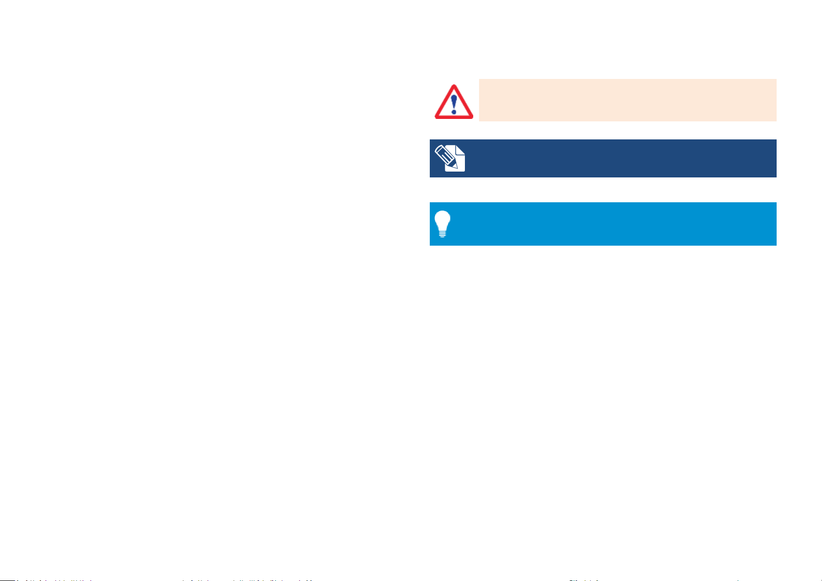
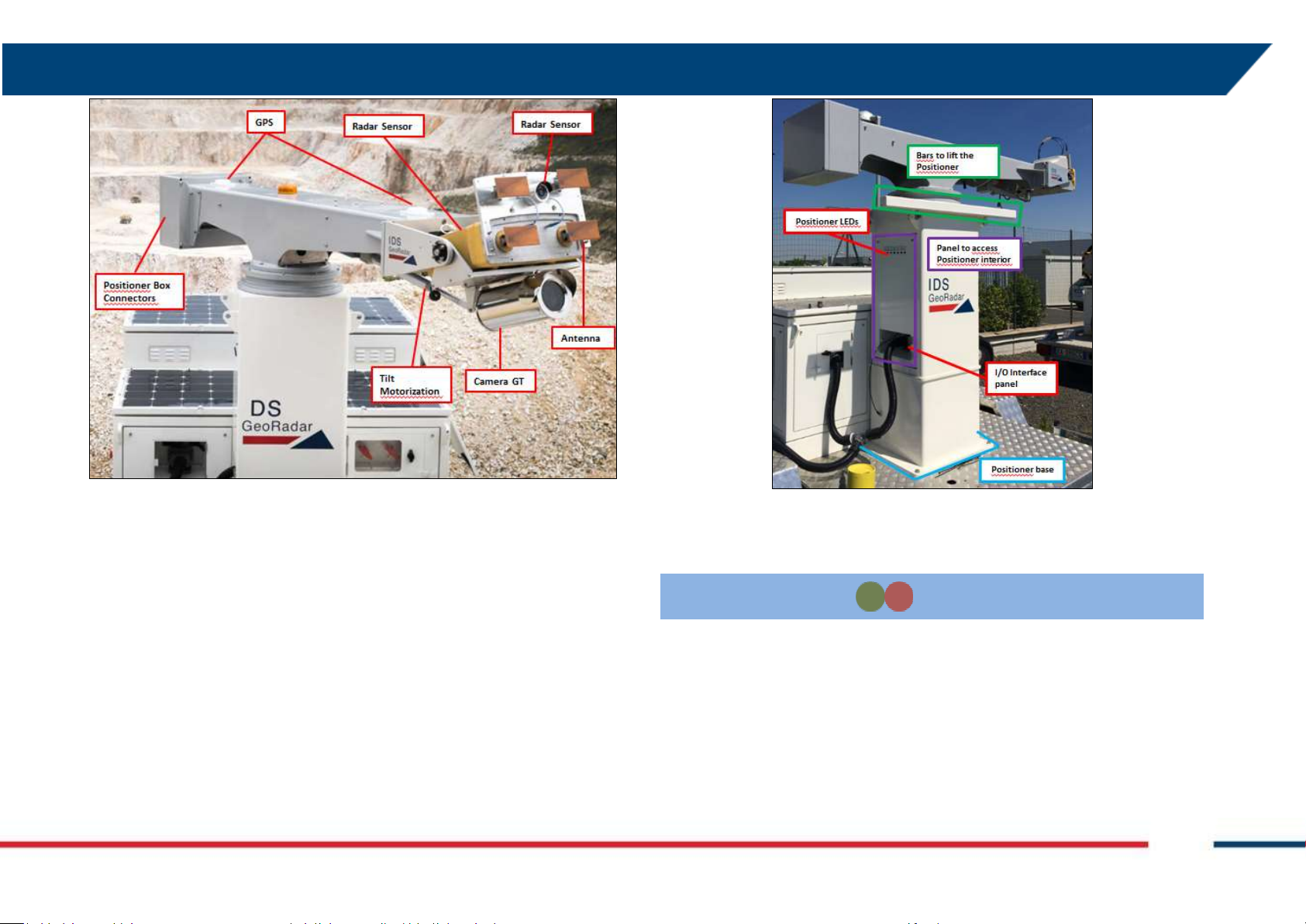
Fig. 1 and Fig. 2 show a view of the four side of IBIS-ArcSAR system. The basic
components are:
The IBIS-ArcSAR system offers the following advantages over the currently
available monitoring systems (GPS, total stations, extensometers):
IBIS-ArcSAR permits the operator to perform remote monitoring of the area
ArcSAR Acquisition Unit: made of Positioner, Radar Sensor, Antennas,
Pointing Camera, Panoramic Camera and GPS;
Positioner: it is device that allows the movement in azimuth
(remote sensing), without needing to access the area to install sensors or
optical targets;
Confidential Information - Do Not Distribute
and tilt of sensor and the panoramic camera. The
movements are controlled by the Controller SW. The

3 GENERAL DESCRIPTION
positioner is able to rotate within 360°. The radar view can
therefore be 360° wide.
Radar Sensor: it generates, transmits and receives the
electromagnetic signal. The Radar Sensor is installed at the
edge of the positioner arm. The movement of the Radar
Sensor around the positioner permits the utilization of the
ArcSAR technique, which obtains a 3D image of the
scenario;
Antennas: proper antennas are required to make the Radar
Sensor properly transmitting and receiving RF signals;
The optional components are:
Generator: it is the main source of power used to recharge
the battery pack when connection to the grid is not
available. It can be configured to automatically start when
required;
ArcSAR Trailer: it permits the mobilization of the IBIS-
ArcSAR and gives extreme stability to the Acquisition Unit
during the monitoring session thanks to hydraulic jacks.
Integrated Solar Panels: for recharging the battery pack
therefore reducing the generator running time;
Pointing Camera: mounted right over the Radar Sensor, it
helps to easily define the area of interest. A video
streaming is in fact integrated in the Controller Software to
get a real time feedback of the Radar current pointing
direction during the session setup.
Panoramic Camera: installed below the radar trolley, it
provides 360° high-resolution geocoded images of the
scenario;
GPS: to automatically retrieve the information needed for
the geocoding (Radar position and bearing);
Wind turbine: for recharging the battery pack therefore
reducing the generator running time;
Weather Station: it provides information about the
atmospheric conditions;
Wi-Fi Bridge: it permits data transmission from IBIS-ArcSAR
to the Control Room;
Low temperature kit: it allows the IBIS-ArcSAR operation in
extremely cold environments;
ArcSAR Supply Unit: this module is in charge of giving power supply
and control to the Acquisition Unit and to other optional devices
such as WIFI antenna and weather station; It is composed of:
Laptop PC: it is equipped with the system management
software (IBIS Controller Software). This is used to setup
the acquisition parameters, store the data and transmit
them to the control room;
Battery pack: this is the main source for supplying the
Acquisition System and all the other devices;
IDS GeoRadar S.r.l. Confidential Information - Do Not Distribute MNG/2017/0016 Rev 1.0 9/ 78
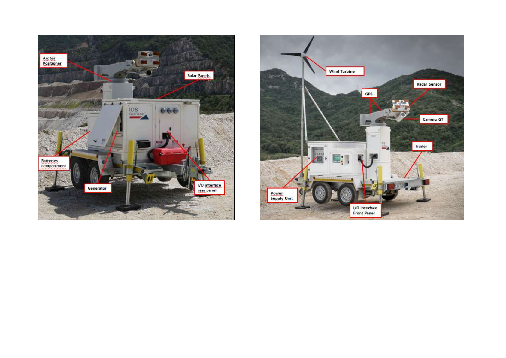
Fig. 1 – IBIS-ArcSAR system (rear and right side)
Confidential Information - Do Not Distribute
Fig. 2 – IBIS-ArcSAR system (front and left side)
4 IBIS-ArcSAR HARDWARE BREAKDOWN
4 IBIS-ArcSAR HARDWARE BREAKDOWN
The trailer is provided with a car connector to supply the rear positioning
lights of the trailer.
This section of the manual provides a detailed description of the
components making up IBIS-ArcSAR system:
The system configuration depends on the selected purchase options, the
system may not include some of the items specified below.
4.1 ArcSAR Trailer
The ArcSAR Trailer (Fig. 3) is the basis where the IBIS-ArcSAR Base is set. It is
provided with a hook to tow the trailer with a vehicle. At every corner there
is a hydraulic support legs (or jacks) whose task is ensuring the stability of
the trailer during IBIS-ArcSAR operation. Trailer is equipped with
mechanical brakes plus a hand brake for parking. Next to the wheels four
yellow chock levels are provided to increase the working security when the
trailer is parked.
The supplying of the trailer supports is provided by a cable to connect to
the main I/O interface panel, placed on the rear side of ArcSAR Supply Unit.
A battery cut-off is provided to isolate the supplying of hydraulic supports
(Fig. 28).
4.2 ArcSAR Acquisition Unit
This system is made of Positioner, Radar Sensor, Antennas, Pointing
Camera, Camera GT and GPS
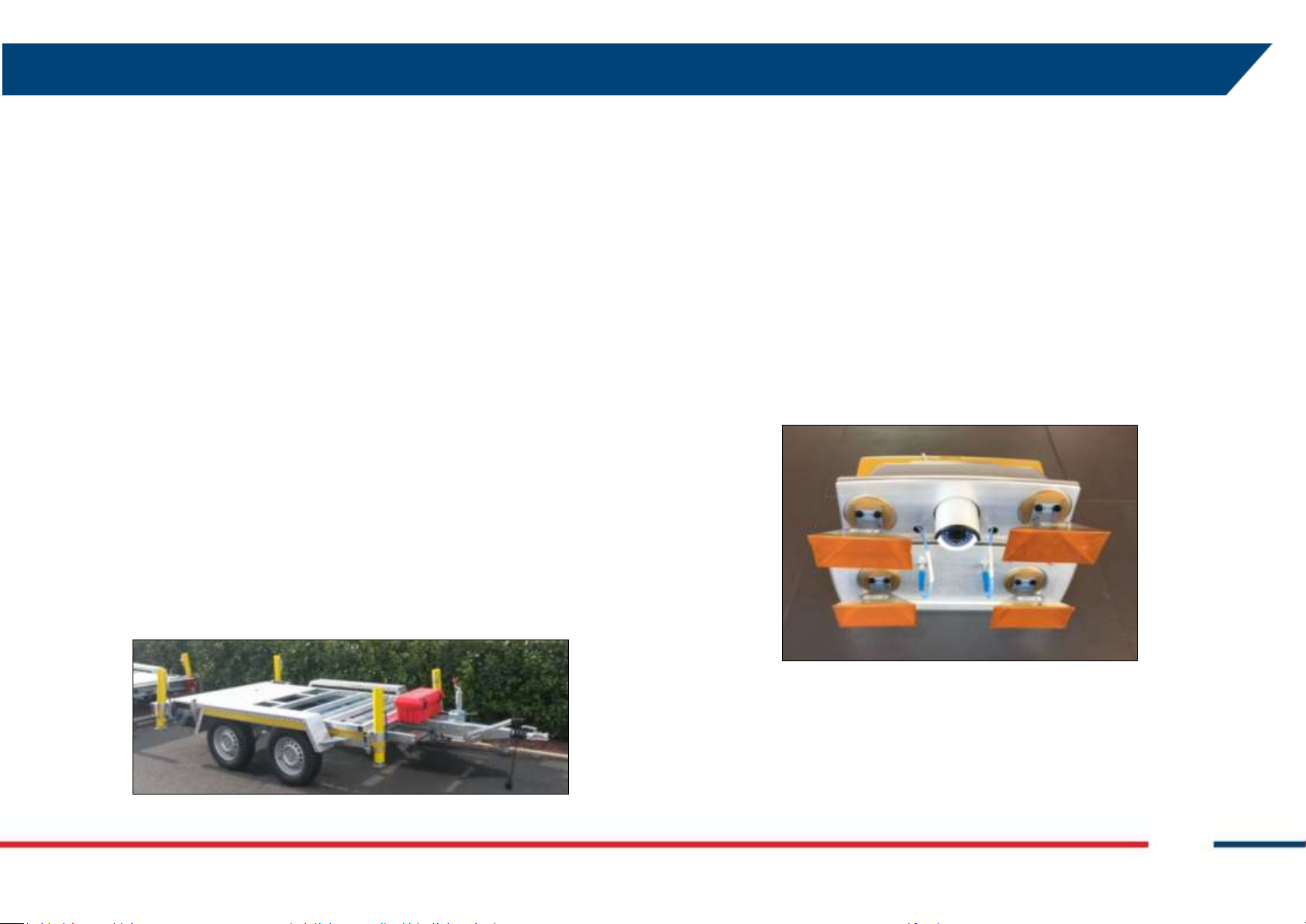
4.2.1 IBIS Radar Sensor
The IBIS Radar Sensor is a unit containing all the parts for the generation,
transmission, reception and acquisition of the radar signal. The Radar
Sensor is shown in Fig. 4 and can be seen as a yellow box.
Fig. 3 - View of the ArcSAR Trailer
IDS GeoRadar S.r.l. Confidential Information - Do Not Distribute MNG/2017/0016 Rev 1.0 11/ 78
Fig. 4 – IBIS Radar Sensor front view
The Radar Sensor has the following interfaces (see Fig. 5 and Fig. 6):
Ethernet type and Supply sockets on the case back-side;
#4 threaded holes and a central pivot on the case bottom-side to fix
the sensor to Positioner trolley;
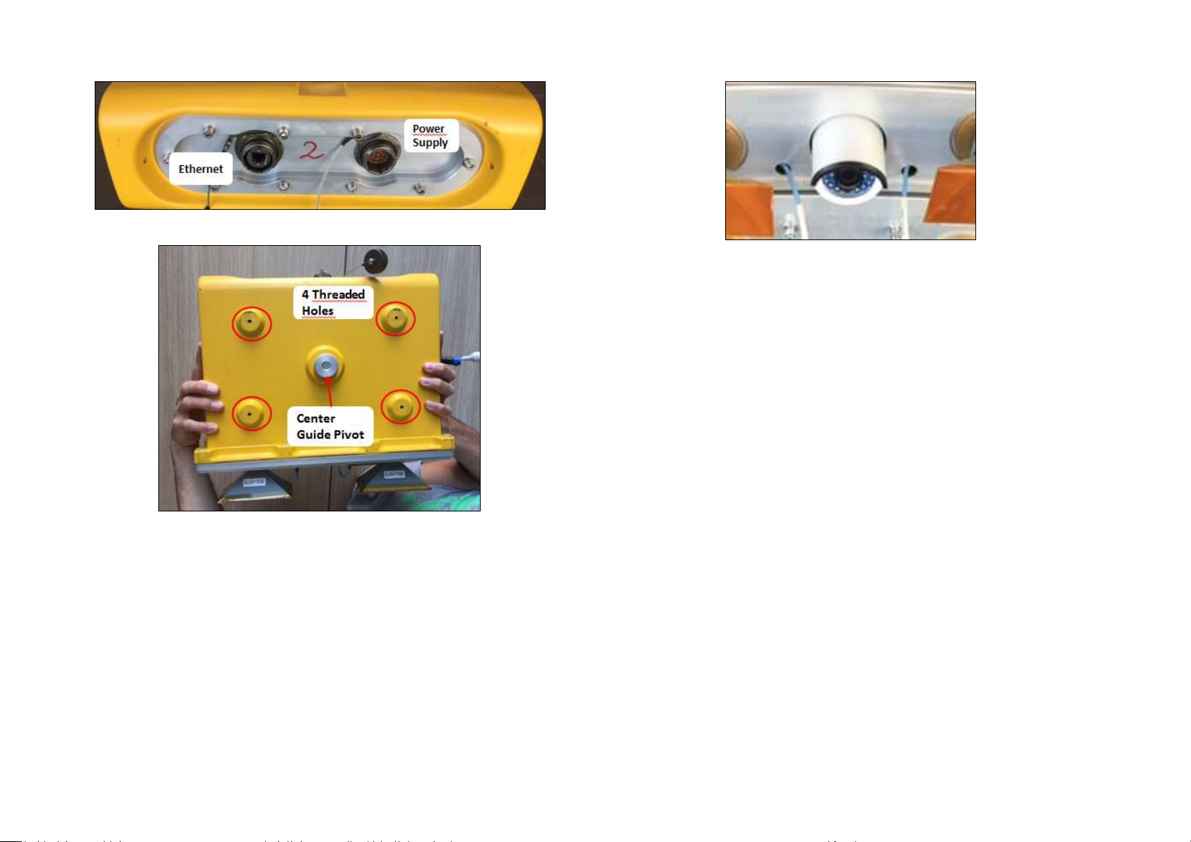
Fig. 5 – Back view of the Radar Sensor
Fig. 6 – Bottom view of the Radar Sensor
4.2.2 Radar Sensor Pointing Camera
The Pointing Camera is used to easily define the borders of the area to
cover with IBIS monitoring. This action is performed during the Controller
session wizard, where the user has to set manually the limits of the
scenario. The Pointing Camera provides a real-time streaming to the user
therefore giving a precise feedback on the actual radar pointing direction.
Pointing Camera is installed on the top cover of the Radar Sensor (Fig. 7) and
it is automatically supplied by the Positioner. Pointing Camera connections
consist of an Ethernet wire and a power wire (12Vdc).
Fig. 7 – ArcSAR Pointing Camera
4.2.3 Antennas (Ku band)
The Ku band IBIS-ArcSAR system is provided with four IBIS-ANT7 antennas
installed at slightly different elevations operating in vertical polarization.
The combination of four antennas installed at different elevations simulates
the vertical movement of the sensor, thus allowing the DEM creation.
4.2.4 Positioner
The Positioner (Fig. 8) is equipped of 2 motorizations: the tilt, which is used
to facilitate radar pointing and the azimuth, which is used to perform
ArcSAR scans (radial).
Confidential Information - Do Not Distribute
4 IBIS-ArcSAR HARDWARE BREAKDOWN
TRANSPORT
Transport mode
solid
Green when the system can
be moved. Red when the
system cannot be moved
Fig. 8 – Positioner top part
Tilt: Radar sensor tilt can range between +/-25° with an accuracy of
0.1°;
Azimuth: the main horizontal beam can rotate from -180° to +180°
with an accuracy of 0.01°;
Once tilt angle has been defined, ArcSAR scans with different angles can be
performed to extend or reduce the Radar Sensor field of view.
IDS GeoRadar S.r.l. Confidential Information - Do Not Distribute MNG/2017/0016 Rev 1.0 13/ 78
Fig. 9 – Positioner base
On the left side of the Positioner column, there are 6 LEDs (Fig. 9 –
Positioner base).
Tab. 1 summarizes the meaning the LEDs.
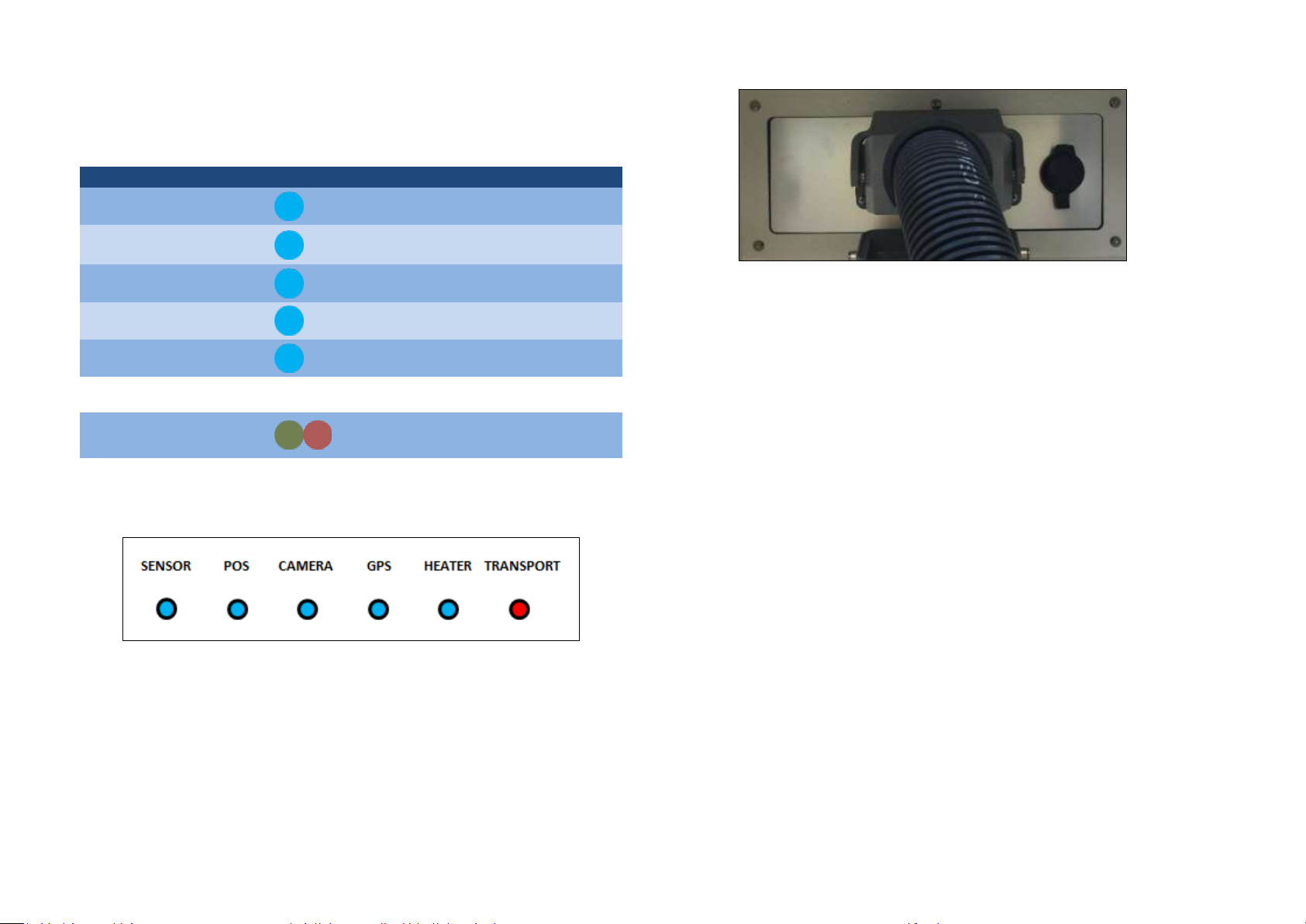
Label
Part
LED color
Meaning
SENSOR
Radar Sensor
solid
Related part powered
POS
Pointing motors
solid
Related part powered
CAMERA
Panoramic and
Pointing camera
solid
Related part powered
GPS
GPS
solid
Related part powered
HEATER
Low temperature
kit
solid
Related part powered
TRANSPORT
Transport mode
solid
Green when the system can
be moved. Red when the
system cannot be moved
Fig. 11 – I/O interface Positioner panel
SOCKET POSITIONER: this socket allows the power supply and control
of the acquisition unit (sensor, positioner, cameras and GPS)
Just below the rotating arm, two metal bars are provided to facilitate the
lifting and moving of the Positioner during ArcSAR first configuration.
The Positioner base has holes placed at every corner to allow the fixing of
the whole frame to the Trailer deck.
At the Positioner base there is an I/O Interface panel that included the
following sockets (Fig. 11):
Confidential Information - Do Not Distribute
Tab. 1 – Positioner LEDs meanings
Fig. 10 – Positioner LEDs
4.2.5 Panoramic Camera
Fixed below the radar trolley the camera (Fig. 14) rotates accordingly to the
positioner movement, providing 360° geocoded images of the scenario.
The camera combines long range surveillance capabilities with the
possibility to acquire 16 Mpixel pictures that are single panoramic views of
the entire scenario, arranged in layers of different image resolution. The
integration between the Panoramic Camera and the IBIS-ArcSAR provides
several additional features:
correlate the picture scenario with a given Guardian radar map, thus
enabling the visual recognition of moving areas;
These features are made possible thanks to the use of:
high resolution panoramic views of the scenario, obtained by
stitching several images in a single one. Views can be acquired on a
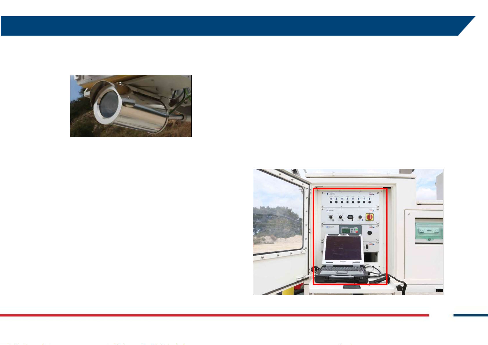
4 IBIS-ArcSAR HARDWARE BREAKDOWN
user request or automatically taken by the system following a userdefined time schedule;
Weather Station, Wi-Fi and Generator Solar Panel can be installed on a
pole, whose casing is on the rear side of the ArcSAR Supply Unit.
photo Georeference and link to digital terrain models. The camera
acquisition geometry is needed to enable the geocoding.
Fig. 14 – Camera fixed below the sensor trolley
4.2.6 GPS
During the Controller session setup allows to obtain the system position
and northing.
4.3 ArcSAR Supply Unit
This module is in charge of giving power supply and control to the
Acquisition Unit and to other optional devices as Wi-Fi radios and weather
station (both mounted on a dedicated pole) (Fig. 34 and ).
On the bottom part of the Supply Unit side a holes grid is present to allow
the installation of the Supply Unit on the trailer deck.
4.3.1 Electrical modules
The PSU supplies electric power to the system. Its function is:
distribute power and signals to the ArcSAR Positioner, Radar Sensor
and other peripherals included in the system;
receive power from the Generator, Solar Panels or from AC Mains
supply and charge the batteries required to guarantee a continuous
power supply, even if a blackout occurs;
The ArcSAR Supply Unit allows the supplying and the control of all the
devices included in the ArcSAR Positioner. In addition, it allows the
communication between the field Laptop and the Control Room.
ArcSAR Supply Unit includes the Power Supply Unit with the ArcSAR battery
pack, the Laptop PC, the Generator set and the Solar Panels.
IDS GeoRadar S.r.l. Confidential Information - Do Not Distribute MNG/2017/0016 Rev 1.0 15/ 78
Fig. 12 – Power Supply Unit position on the left side of the IBIS-ArcSAR
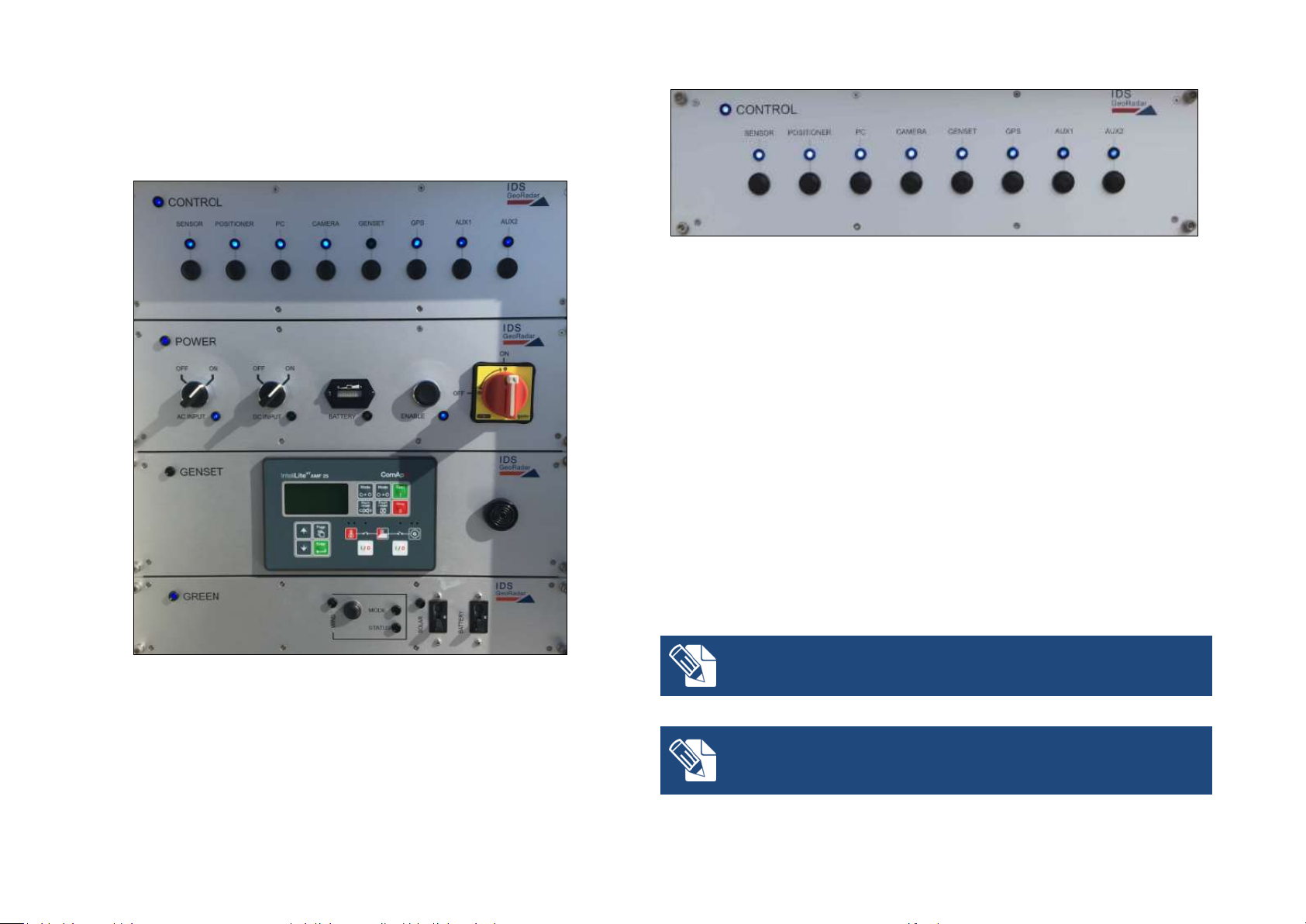
The PSU is composed by drawers which are called modules, placed on the
Every time the system is shut down and then supplied again, it is always
necessary to press the enable switch in order to switch on the system
The DC Input switch has to be turned on when for example an external battery
pack is connected to the system. After connecting the external battery pack
and turning on the DC Input switch, the entire system automatically turns off
and it is necessary to press again the Enable switch to restore the system
left side of the ArcSAR Supply Unit. A front door gives access to them (Fig.
12). Description of the front side of each module follows here below.
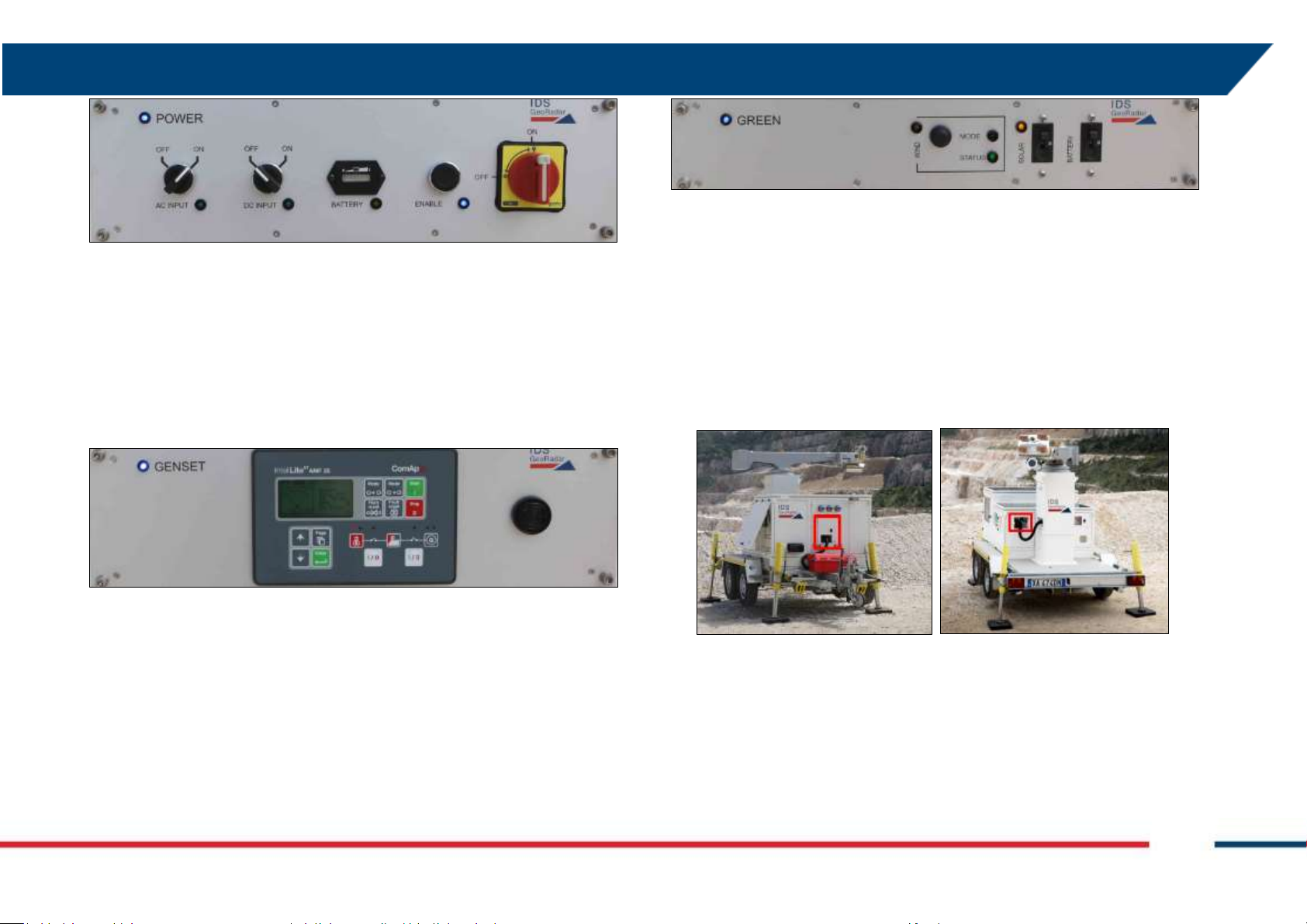
Fig. 14 – Front side of the Control module
Power module (Fig. 15): it contains the following components (from
left to right):
AC Input switch: it permits to supply the system by AC voltage
from mains or Generator. The LED is lit up in blue when the
voltage is present.
DC Input switch: it permits to supply the system by DC current
provided by external source. The LED is lit up in blue when the
voltage is present.
Battery: this indicator shows the charge level of the batteries.
The LED is lit up in orange when the batteries are charging;
Fig. 13 – Modules on the front side of PSU
Control module (Fig. 14): it contains electrical switches which permit
to supply (from left to right) Radar Sensor, Positioner, acquisition
Laptop PC, Panoramic Camera, Genset Module, GPS, AUX1 socket,
AUX2 socket;
Confidential Information - Do Not Distribute
Enable switch: it permits to supply all the modules of the PSU;
ON/OFF Switch: it interrupts the power supplying of the
system, including the charging of the batteries;
4 IBIS-ArcSAR HARDWARE BREAKDOWN
Fig. 17 – Front side of the Green module
Fig. 15 – Front side of the Power module
Genset module (Fig. 16) is provided along with the integrated
generator: it contains the Generator control unit AMF25 which can
start or stop the generator and manage alarm and warning signals
from the generator sensors (e.g. lack of oil, empty tank, etc.). On the
right hand side (see Fig. 16) there is a horn which activates when
AMF25 alarm/warning is present; AMF25 is already set and ready to
communicate with the PSC board into the Control module;
Fig. 16 – Front side of the Genset module
Green module (Fig. 17) is associated to solar panels and wind turbine.
It contains following parts:
WIND: it includes the button to brake the wind turbine and the
LEDs to check the charging status and working mode
The Module On blue LED on the upper left of every modules indicates when
they are powered and active. The Power, Control and Green modules turn
on when the Enable switch on Power Module is switched on. The Genset
Module turn on when the Genset switch on Control Module is switched on.
4.3.2 I/O panels
The I/O interfaces are set in two panels, located on the front and rear sides
of the ArcSAR Supply Unit, as shown in Fig. 18Figure 1.
Fig. 18Figure 1 – Positions of the I/O interfaces panels on IBIS-ArcSAR
SOLAR: it includes the switch to turn on the solar panels input
and the LED to check the charging status;
BATTERY: this switch allows the power flowing from the green
sources to the ArcSAR batteries;
IDS GeoRadar S.r.l. Confidential Information - Do Not Distribute MNG/2017/0016 Rev 1.0 17/ 78
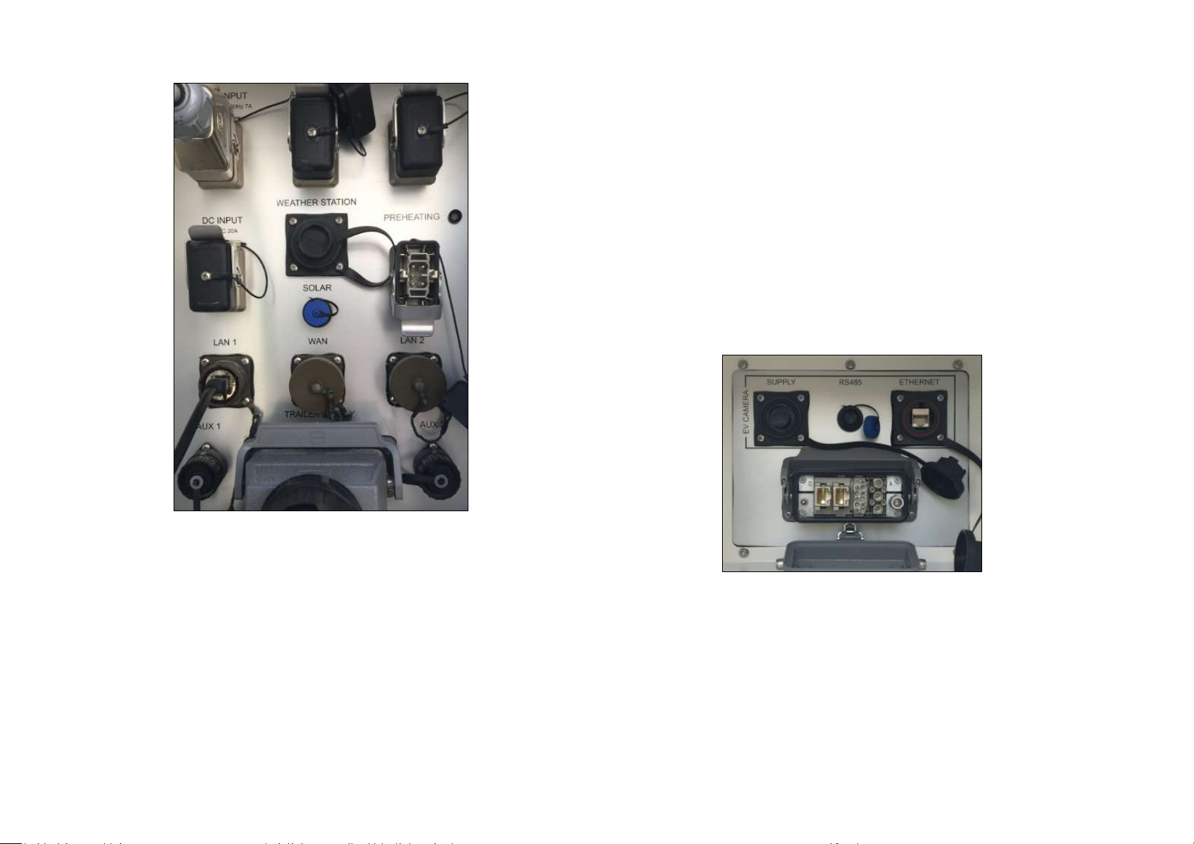
PREHEATING: socket for preheating system (low temperature kit)
SOLAR (12 Vdc – 2 A): a plug for a solar panel which could be used to
charge the Genset battery;
LAN 1: Ethernet port connected to router LAN port;
WAN: Ethernet port connected to router WAN port;
LAN 2: Ethernet port connected to router LAN port;
AUX1 (12, 24, 48 Vdc – 4 A) outlet;
TRAILER SUPPLY (12 Vdc – 10 A) cable socket;
AUX2 (12, 24, 48 Vdc – 2 A) outlet;
Fig. 19 – Interface panel on the rear side of the IBIS-ArcSAR Supply Unit
The I/O interfaces panel shown on front of Fig. 18Figure 1 includes (from
upper left to lower right in Fig. 19):
Fig. 20 – Interface panel on the front side of the ArcSAR Supply Unit
MAINS INPUT (100-240 Vac 50-60 Hz – 7 A) AC Mains connection;
AC OUTPUT (230 Vac 50 Hz 10 A): 230 Vac outlet for supplying
The I/O interfaces panel placed on the front side includes (from left to right
in Fig. 20):
auxiliary equipment (only when the onboard generator is on);
SOCKET POSITIONER: this socket allows the power supply and control
WIND: socket for Wind Turbine;
DC INPUT: connection for external battery pack;
of the acquisition unit (sensor, positioner, cameras and GPS)
EV CAMERA section: not applicable to the ArcSAR system
WEATHER STATION: socket for IBIS Weather Station;
Confidential Information - Do Not Distribute

4 IBIS-ArcSAR HARDWARE BREAKDOWN
No communication software such as Firewall, Wi-Fi or antivirus must be
installed to avoid any conflict with the IBIS Controller software
The IBIS-ArcSAR is provided of four batteries which supply the system.
These batteries are set in an internal compartment placed on the right side
of the ArcSAR Supply Unit (Fig. 21).
Fig. 21 – Batteries compartment on the right side of IBIS-ArcSAR Supply Unit
4.3.3 Laptop PC
The Laptop PC workspace is placed under the drawers of the Power Supply
Unit, in the left side of IBIS-ArcSAR (Fig. 22). The workspace is the lower
sliding drawer, as shown in Fig. 23.
The Laptop is used to control the Radar Sensor, the Positioner and the
other ArcSAR devices, manage the supplying of the System and allows the
communication between the field and the IBIS Guardian processing
software.
Fig. 22 – Laptop drawer
The provided Laptop PC is a Panasonic Toughbook CF31 and it is supplied
with the IBIS Controller control and data acquisition software pre-installed.
IDS GeoRadar S.r.l. Confidential Information - Do Not Distribute MNG/2017/0016 Rev 1.0 19/ 78
Fig. 23 – Panasonic Toughbook CF31
IDS GeoRadar takes no responsibility for bad functioning if there is a
functional conflict between its software and any software installed on
the Laptop PC by the user. IDS GeoRadar does not guarantee that the
performance of its equipment will be maintained using a different
configuration from the recommended one
4.3.4 Generator
The integrated diesel generator (also known as Genset) is used as a back-up
source of energy. It is automatically managed with the software, so that
when batteries are low (and no energy is coming from the solar panels) it is
turned on to provide power.
Fig. 24 – Generator on the ArcSAR left side
Fig. 25 – Generator on the ArcSAR right side
The control unit, placed on Genset Module of the PSU, can start or stop the
Genset and manage alarm and warning messages from the Genset sensors
(e.g. lack of oil, empty tank, etc.).
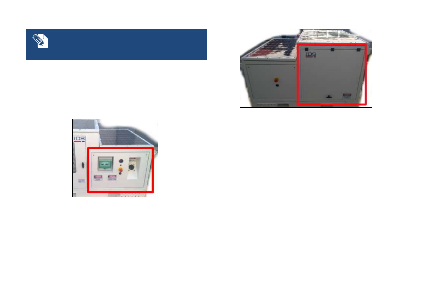
The Generator is installed and accessible from the right side of the IBISArcSAR. The Generator area can be divided in:
the left side includes the filling point for the fuel tank, the System
emergency stop red button with the related horn and the fuel level
indicator (Fig. 26); it also includes Circuit Breaker switchboard, with
the Generator general switch and a 220 Vac output switch (Fig. 99);
the right side is marked by a lifting door; the generator is located
behind the main door.
Confidential Information - Do Not Distribute
4.3.5 Electrical safety devices
IBIS-ArcSAR is provided of several electrical safety devices. In detail:
a red emergency stop button placed next to the generator fuel level
indicator;
a red emergency stop button placed on the battery panel side;
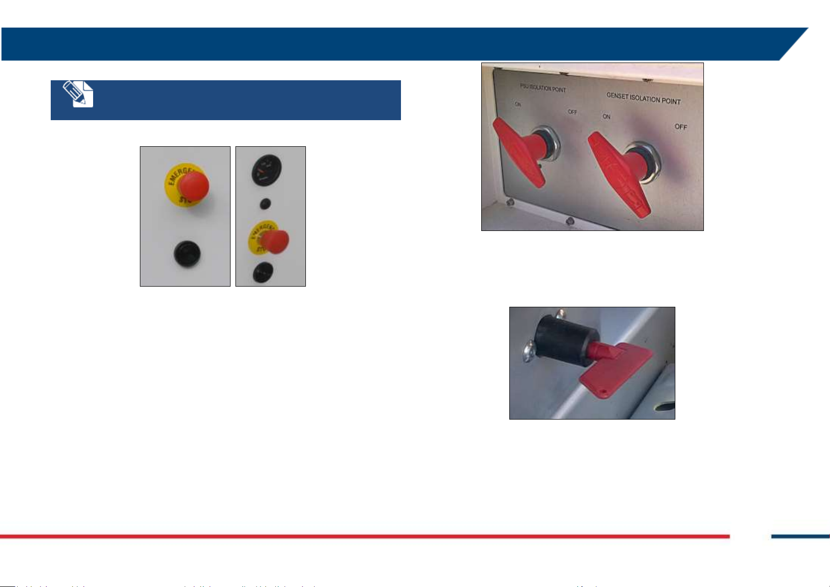
4 IBIS-ArcSAR HARDWARE BREAKDOWN
Every time the emergency stop button is released, the enable switch
has to be pressed to restore the system.
Fig. 26 – Red emergency stop buttons
two isolation points (red lever switches) placed on the front side of
the IBIS-ArcSAR: the left one allows the electrical isolation of PSU
batteries, the right one allows the electrical isolation of GENSET
battery (Fig. 27). The panel that contains these two switches can be
locked if necessary;
Fig. 27 – PSU and GENSET isolation points
an isolation point (a battery cut-off switch commanded with a key)
which allows the electrical isolation of the trailer lifting supports only
(Fig. 28).
IDS GeoRadar S.r.l. Confidential Information - Do Not Distribute MNG/2017/0016 Rev 1.0 21/ 78
Fig. 28 – Battery cut-off switch
4.4 Pole
The rear side of the ArcSAR is provided with a metallic pole. On the pole
can be installed optional components, as Weather Station or Wi-Fi Link or
the Genset solar panel. This pole can reach a height of about 3 meters from
its base (the total height depends on the trailer specs). The pole can be
tilted to facilitate the installation of every single component on it. Pole can
be rotated to point the Wi-Fi antenna towards the desired location.
4.5 Additional items
Additional items are part of the IBIS-ArcSAR, shipped together with the
devices explained in the paragraphs below.
IBIS Radar Sensor Case
AC Mains cable (Fig. 148);
Supply Output cable to provide 220 Vac while generator is running
(Fig. 29);
Fig. 29 – 220 Vac output cable
2 Ethernet cable (Fig. 30);
Fig. 30 – Ethernet cable
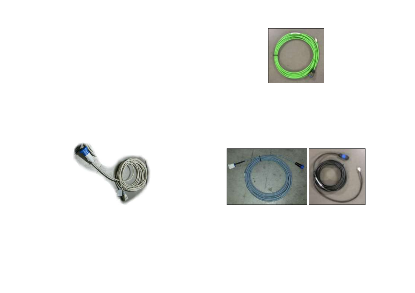
1 48 V Power-over-Ethernet Wi-Fi Link cable (Fig. 39);
1 24 V Power-over-Ethernet cable (Fig. 39);
1 Aux 12 V cable (Fig. 31);
1 Aux 24 V cable (Fig. 31);
Fig. 31 – Aux 12 V - 24 V cables
External cable for Generator battery;
An additional cable is provided to supply the system with Mains AC power.
The power cable has a plug whose shape is suitable for the destination
country electric system.
Confidential Information - Do Not Distribute
4 IBIS-ArcSAR HARDWARE BREAKDOWN
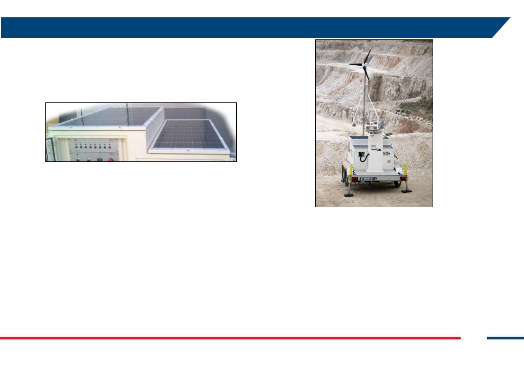
4.6 Solar Panels
The Solar Panels permit to exploit the solar irradiation and the reduction of
the need of the generator, therefore reducing its maintenance and fuel
consumption. The panels are placed on the top covers of IBIS-ArcSAR and
mounted on their frame.
Fig. 32 – Solar Panels
The solar panels are managed by Green Module placed on the PSU.
4.7 Wind Turbine (optional)
Fig. 33 – Wind Turbine
The Wind Turbine generates power from wind and helps to reduce of the
need of the generator, therefore reducing its maintenance and fuel
consumption. The Wind Turbine is installed on a pole mounted on the
Trailer shaft
IDS GeoRadar S.r.l. Confidential Information - Do Not Distribute MNG/2017/0016 Rev 1.0 23/ 78
The Wind Turbine is managed by Green Module placed on the PSU.
4.8 Weather Station (optional)
Weather Station provides info about meteorological data. The weather
sensors are temperature, pressure, humidity, wind speed and direction,
rain precipitation, Data Logger with internal temperature, pressure and
humidity (integrated in the ArcSAR PSU).
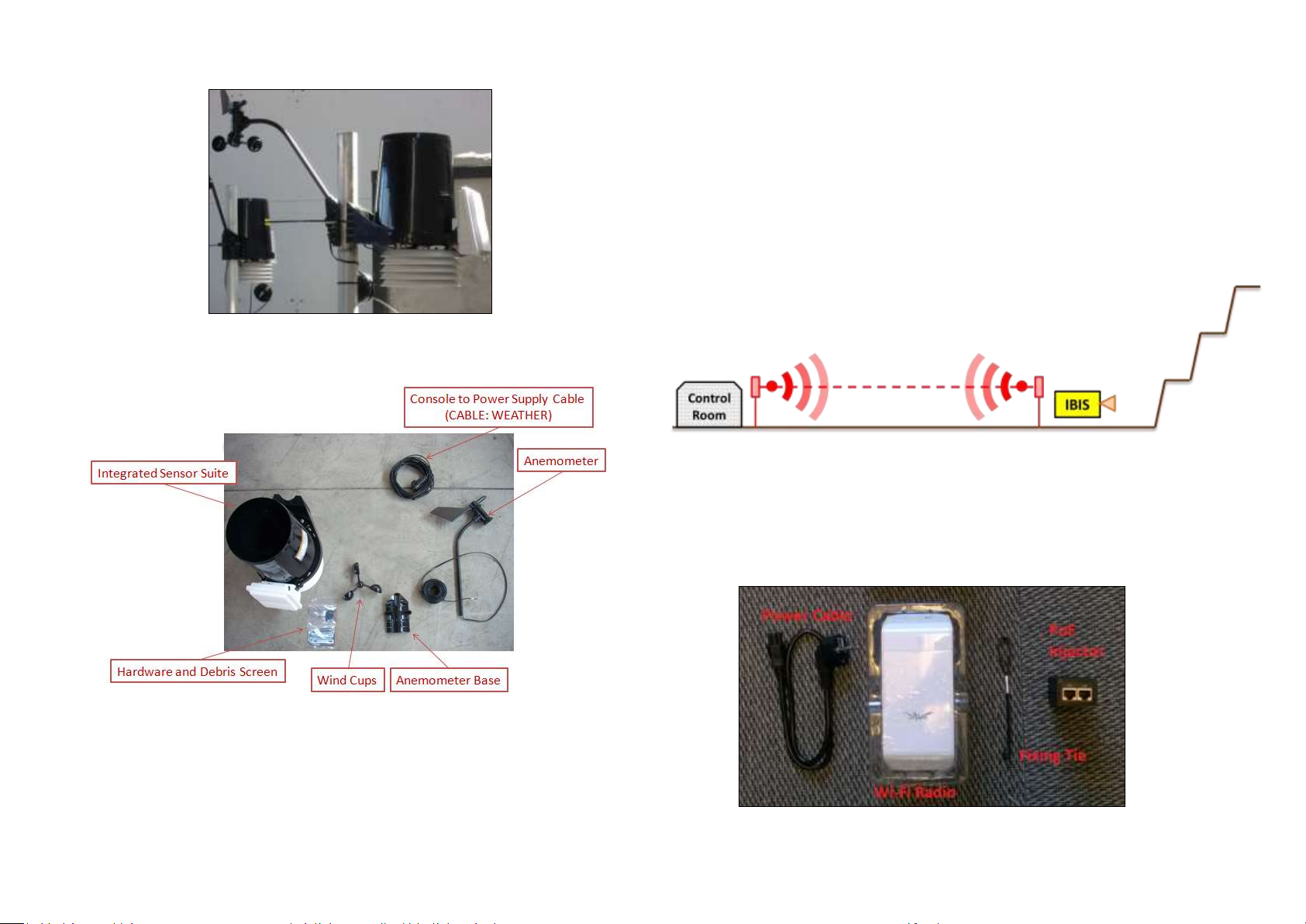
Fig. 34 – View of the Weather Station
4.9 Wi-Fi Link (optional)
The Wi-Fi link allows the data transmission between the IBIS-ArcSAR
installation site, where IBIS Controller is installed on CF31, and the Control
Room, where IBIS Guardian workstation is present.
The basic layout of Wi-Fi Link is when the mine facilities have free line of
sight to the IBIS-ArcSAR or when their distance is less than 2 km (Fig. 36).
Fig. 36 – Wi-Fi Link with no Repeater
In this case the Wi-Fi Link is composed of a couple of Wi-Fi radios, supplied
by Power-over-Ethernet. One radio is located on the IBIS-ArcSAR, the other
radio is installed at the Control Room, and it’s connected to the IBIS
Guardian workstation.
Fig. 35– Components of the Weather Station
Please refer to the provided Weather Station manual for further details.
Confidential Information - Do Not Distribute
Fig. 37 – Content of a Wi-Fi radio box
 Loading...