

IDS GeoRadar s r l DUALF 400 900 User Manual

Tot pag. N°. = 45
- PRO/010/M1 Rev 4 -
RIS Hi-Mod /
DUALF-400-900 Installation Guide
and User Manual
INGEGNERIA DEI SISTEMI S.p.A.
Rev. 1.1
Protocol: MN/2009/056
RIS Hi-Mod / DUALF-400-900 Systems
Installation Guide and User Manual
Pisa, November 2010

IDS Ingegneria Dei Sistemi S.p.A.
Protocol: MN/2009/056 - Rev. 1.1
RIS Hi-Mod / DUALF-400-900 - Installation Guide
and User Manual
Document Evolution
Revision
Date
Reason for change
Rev. 1.0
August 2009
First edition
Rev. 1.1
November 2010
DUALF-400-900 added
OUR CONTACTS
IDS Ingegneria dei Sistemi S.p.A. – GeoRadar Division
Via Enrica Calabresi, 20
56121 Montacchiello (PISA) - ITALIA
Tel: +39.050.3124350
Fax: +39.050.3124205
inforis@ids-spa.it
Customer Care department:
customercare.gpr@ids-spa.it
Tel.: +39.050.3124 355/356
Sales & Marketing department:
sales.gpr@ids-spa.it
Tel.: +39.050.3124352
2 / 45

IDS Ingegneria Dei Sistemi S.p.A.
Protocol: MN/2009/056 - Rev. 1.1
RIS Hi-Mod / DUALF-400-900 - Installation Guide
and User Manual
DISCLAIMER
IDS WILL NOT BE HELD RESPONSIBLE FOR THE CONSEQUENCES OF AN
IMPROPER USE OF THE EQUIPMENT AND/OR THE SOFTWARE.
THIS SOFTWARE MAY INCLUDE AUTOMATED DATA PROCESSING AND
ANALYSIS TOOLS.
WHILE EVERY EFFORT IS MADE TO ENSURE THE ACCURACY OF THE
INFORMATION PROVIDED BY THOSE TOOLS, THEY MUST NOT BE
INTENDED AS A SUBSTITUTE FOR INTELLIGENT ANALYSIS; RATHER, THEY
HAVE TO BE INTENDED AS AN ADVISOR AND THE USER MUST NOT
COMPLETELY RELY ON THE RESULTS PROVIDED BY THEM TO GIVE THE
COMPLETE ANSWER.
IDS INGEGNERIA DEI SISTEMI SPA ASSUMES NO LIABILITY FOR ANY
DIRECT, INDIRECT, SPECIAL, INCIDENTAL OR CONSEQUENTIAL DAMAGES
OR INJURIES CAUSED BY SUCH RELIANCE ON THE ACCURACY,
RELIABILITY, OR TIMELESS OF THE INFORMATION PROVIDED BY THOSE
TOOLS.
ANY PERSON OR ENTITY WHO RELIES ON INFORMATION OBTAINED FROM
THE AUTOMATED DATA PROCESSING/ANALYSIS TOOLS ONLY, DOES SO AT
HIS OR HER OWN RISK
3 / 45

IDS Ingegneria Dei Sistemi S.p.A.
Protocol: MN/2009/056 - Rev. 1.1
RIS Hi-Mod / DUALF-400-900 - Installation Guide
and User Manual
SAFETY INFORMATION
The equipment conforms to the following requirements set by EC
regulations, including subsequent modifications, and to the legislation set
by the member states that implement these regulations:
1999/05/EEC Radio Directive
Warning: this equipment is destined for use in industrial environments
(Class A apparatus). In residential, commercial and light industry
environments, this apparatus may generate radio interference: in this case,
the user may be required to operate while taking appropriate
countermeasures.
The apparatus is sensitive to the presence of external electromagnetic fields,
which may reduce its performance.
4 / 45

IDS Ingegneria Dei Sistemi S.p.A.
Protocol: MN/2009/056 - Rev. 1.1
RIS Hi-Mod / DUALF-400-900 - Installation Guide
and User Manual
IMPORTANT NOTE FOR THE US CUSTOMERS
FCC ID: UFW-HI-MOD
This device complies with part 15 of the FCC Rules:
Operation is subject to the following conditions:
1. This device may not cause harmful interference, and
2. This device must accept any interference received, Including interference that may cause undesired
operation
Warning: Changes or modifications to this unit not expressly approved by the party responsible for
compliance could void the user’s authority to operate the equipment.
Operation of this device is restricted to law enforcement, fire and rescue officials, scientific research
institutes, commercial mining companies, and construction companies. Operation by any other party is a
violation of 47 U.S.C. § 301 and could subject the operator to serious legal penalties.
Coordination Requirements.
(a) UWB imaging systems require coordination through the FCC before the equipment may be used. The
operator shall comply with any constraints on equipment usage resulting from this coordination.
(b) The users of UWB imaging devices shall supply detailed operational areas to the FCC Office of
Engineering and Technology who shall coordinate this information with the Federal Government through
the National Telecommunications and Information Administration. The information provided by the UWB
operator shall include the name, address and other pertinent contact information of the user, the desired
geographical area of operation, and the FCC ID number and other nomenclature of the UWB device. This
material shall be submitted to the following address:
Frequency Coordination Branch., OET
Federal Communications Commission
445 12th Street, SW
Washington, D.C. 20554
ATTN: UWB Coordination
(d) Users of authorized, coordinated UWB systems may transfer them to other qualified users and to
different locations upon coordination of change of ownership or location to the FCC and coordination with
existing authorized operations.
(e) The NTIA/FCC coordination report shall include any needed constraints that apply to day-to-day
operations. Such constraints could specify prohibited areas of operations or areas located near authorized
radio stations for which additional coordination is required before operation of the UWB equipment. If
additional local coordination is required, a local coordination contact will be provided.
(f) The coordination of routine UWB operations shall not take longer than 15 business days from the receipt
of the coordination request by NTIA. Special temporary operations may be handled with an expedited turnaround time when circumstances warrant. The operation of UWB systems in emergency situations
involving the safety of life or property may occur without coordination provided a notification procedure,
similar to that contained in CFR47 Section 2.405(a)-(e), is followed by the UWB equipment user.
Notice: Use of this device as a wall imaging system is prohibited by FCC regulations.
5 / 45

IDS Ingegneria Dei Sistemi S.p.A.
Protocol: MN/2009/056 - Rev. 1.1
RIS Hi-Mod / DUALF-400-900 - Installation Guide
and User Manual
IMPORTANT NOTE FOR THE US CUSTOMERS
FCC ID: UFW-DUALF-400-900
This device complies with part 15 of the FCC Rules:
Operation is subject to the following conditions:
1. This device may not cause harmful interference, and
2. This device must accept any interference received, Including interference that may cause undesired
operation
Warning: Changes or modifications to this unit not expressly approved by the party responsible for
compliance could void the user’s authority to operate the equipment.
Operation of this device is restricted to law enforcement, fire and rescue officials, scientific research
institutes, commercial mining companies, and construction companies. Operation by any other party is a
violation of 47 U.S.C. § 301 and could subject the operator to serious legal penalties.
Coordination Requirements.
(a) UWB imaging systems require coordination through the FCC before the equipment may be used. The
operator shall comply with any constraints on equipment usage resulting from this coordination.
(b) The users of UWB imaging devices shall supply detailed operational areas to the FCC Office of
Engineering and Technology who shall coordinate this information with the Federal Government through
the National Telecommunications and Information Administration. The information provided by the UWB
operator shall include the name, address and other pertinent contact information of the user, the desired
geographical area of operation, and the FCC ID number and other nomenclature of the UWB device. This
material shall be submitted to the following address:
Frequency Coordination Branch., OET
Federal Communications Commission
445 12th Street, SW
Washington, D.C. 20554
ATTN: UWB Coordination
(d) Users of authorized, coordinated UWB systems may transfer them to other qualified users and to
different locations upon coordination of change of ownership or location to the FCC and coordination with
existing authorized operations.
(e) The NTIA/FCC coordination report shall include any needed constraints that apply to day-to-day
operations. Such constraints could specify prohibited areas of operations or areas located near authorized
radio stations for which additional coordination is required before operation of the UWB equipment. If
additional local coordination is required, a local coordination contact will be provided.
(f) The coordination of routine UWB operations shall not take longer than 15 business days from the receipt
of the coordination request by NTIA. Special temporary operations may be handled with an expedited turnaround time when circumstances warrant. The operation of UWB systems in emergency situations
involving the safety of life or property may occur without coordination provided a notification procedure,
similar to that contained in CFR47 Section 2.405(a)-(e), is followed by the UWB equipment user.
Notice: Use of this device as a wall imaging system is prohibited by FCC regulations.
6 / 45

IDS Ingegneria Dei Sistemi S.p.A.
Protocol: MN/2009/056 - Rev. 1.1
RIS Hi-Mod / DUALF-400-900 - Installation Guide
and User Manual
!
WARNING
CLEANING INFORMATION
Before cleaning any external parts of the apparatus, make sure
that all cables have been disconnected, including the power
supply cable. If a damp cloth is used, make sure it is not too wet,
to avoid any damage to the electrical components of the
equipment. Wait until the equipment is totally dry before
reconnecting the cables.
The Detector Duo should be cleaned periodically using a damp
cloth.
Do not use solvents or abrasive detergents.
Do not apply liquid directly to the electrical contacts of the
various connectors. If a specific spray is used to clean the PC
TFT monitor, make sure it is not flammable; ion any case, do not
spray it directly on the screen, instead, spray it onto the cleaning
cloth.
7 / 45

IDS Ingegneria Dei Sistemi S.p.A.
Protocol: MN/2009/056 - Rev. 1.1
RIS Hi-Mod / DUALF-400-900 - Installation Guide
and User Manual
BATTERIES REMOVAL INFORMATION
Laptop Batteries:
Manufacturer: PANASONIC
Type: Li-ion Ni
Characteristics: 10.65V 5.7Ah
Removal instructions:
1. turn off the laptop;
2. open the drawer with the symbol of the batteries;
3. extract the battery pack pulling the tab.
Radar batteries:
Manufacturer: FIAMM FG21202 / SAFT MP176065
Type: rechargeable lead acid / rechargeable lithium-ion
Characteristics: 12V & 12Ah / 15V & 6.8Ah
Removal instructions:
1. disconnect the battery from the instrument:
a. pull the connector wings;
b. separate the connectors;
2. remove the battery from the cover (optional) opening the
strap.
8 / 45

IDS Ingegneria Dei Sistemi S.p.A.
Protocol: MN/2009/056 - Rev. 1.1
RIS Hi-Mod / DUALF-400-900 - Installation Guide
and User Manual
RECICLYING
The crossed out wheeled bin symbol shown on the equipment indicates that
the product must be recycled separately from other waste at the end of its
useful life.
Separate waste disposal of this product at the end of its useful life will be
organised and managed by IDS. When you decide to dispose of the
equipment, contact IDS and follow the system that IDS has set up to permit
the separate collection of the apparatus at its life end.
Adequate separate collection for its subsequent recycling, treatment and
environmental friendly disposal contribute towards avoiding any
unnecessary effects on the environment and to health and favour the reuse or
recycling of the materials that make up the equipment. Unauthorised disposal
of this product as unsorted waste by its possessor will lead to an
administrative penalty foreseen by national regulations.
9 / 45

IDS Ingegneria Dei Sistemi S.p.A.
Protocol: MN/2009/056 - Rev. 1.1
RIS Hi-Mod / DUALF-400-900 - Installation Guide
and User Manual
WARRANTY CERTIFICATE CONDITIONS
1) IDS Ingegneria dei Sistemi S.p.A, hereinafter referred to as IDS, warrants hardware/software
products for a period of 12 months from the delivery date to the original customer;
2) The delivery date is certified by the “Warranty Registration Form”;
3) IDS’s hardware products will be free from defects in materials workmanship under normal use
and service;
4) IDS’s obligation is limited to repairing or replacing parts or equipment which are returned to IDS,
without alteration or further damage, and which in IDS s judgment, were defective or became
defective during normal use;
5) IDS’ software will have to be installed on a PC according to the requirement of the IDS hardware
( see IDS User’s Guide the Software Data Acquisition);
6) IDS’ s software products designed by IDS for use for IDS hardware products are warranted not to
fail to execute their programming instructions due to defects during the warranty period, provided
they are properly installed on IDS hardware products. IDS does not warrant if the IDS software will
be used and operated in hardware and software combinations not selected by IDS;
7) IDS does not assumes any liability for any direct, indirect, special, incidental or consequential
damages or injuries caused by proper or improper operation of its equipment whether defective or
not defective;
8) This software may include automated data processing and analysis tools. While every effort is
made to ensure the accuracy of the information provided by those tools, they must not be intended
as a substitute for intelligent analysis; rather, they have to be intended as an advisor and the user
must not completely rely on the results provided by them to give the complete answer. IDS assumes
no liability for any direct, indirect special, incidental or consequential damages or injuries caused by
such reliance on the accuracy, reliability, or timeliness of the information provided by those tools.
Any person or entity who relies on information obtained from the automated data
processing/analysis tools only, does so at his or her own risk;
9) IDS’s warranty does not extend and shall not apply to:
a) Products which have been repaired or altered by other than IDS personnel;
b) Products which have been subjected to misuse, neglect, accident or improper installation;
c) Products in which have been installed Hardware/Software accessories not supplied by IDS
and/or without any approval by IDS;
d) Products which have been connected to equipment different from the ones supplied by IDS
(except the PC data Logger which must conform to IDS specifications;
e) Products which have been damaged by natural disaster or calamities.
10) Before returning any equipment to IDS , you have to contact the IDS Customer Care Office that
will authorize you to return the material to be repaired;
11) Once the parts/equipment to be repaired arrive to IDS, IDS may inspect the defective products to
verify they are eligible for repair or replacement. All packing must be saved for inspection purpose
in order to assist IDS to understand the cause of the defects. IDS, will not be obliged to repair, or
replace for products returned as defective but damaged from abuse, misuse, negligence , accident
loss or damage in transit;
12) The final clients, is responsible for ensuring the defective products returned to be properly
packaged;
13) The above warranty are sole and exclusive, and no other warranty, whether written or oral, is
expressed or implied.
10 / 45

IDS Ingegneria Dei Sistemi S.p.A.
Protocol: MN/2009/056 - Rev. 1.1
RIS Hi-Mod / DUALF-400-900 - Installation Guide
and User Manual
INDEX
1. Hardware equipment of the Hi-MOD AND DUALF-400-900 systems ................ 14
1.1 One antenna equipment and configuration ........................................................ 14
Rudder ....................................................................................................................... 14
1.1.1 Assemblage instructions ................................................................................... 14
1.1.2 Wiring............................................................................................................... 19
1.2 Two antennas equipment and configuration ...................................................... 21
Rudder ....................................................................................................................... 22
1.2.1 Assemblage instructions ................................................................................... 22
1.2.2 Wiring............................................................................................................... 25
1.3 Three antennas equipment and configuration .................................................... 27
1.3.1 Assemblage instructions ................................................................................... 27
1.3.2 Wiring............................................................................................................... 29
1.4 Four antennas equipment and configuration ..................................................... 31
1.4.1 Assemblage instructions ................................................................................... 31
1.4.2 Wiring............................................................................................................... 32
2. The DAD Control Unit .............................................................................................. 33
2.1 The Notebook Computer ..................................................................................... 35
2.1.1 Panasonic Toughbook rugged tablet PC .......................................................... 35
2.2 Connecting the DAD Control Unit - Notebook Computer ................................. 36
2.3 Wireless connection ............................................................................................ 39
3. On line assistance ....................................................................................................... 42
3.1 Remote assistance using Webex Support Center ................................................ 42
3.1.1 How to use the Webex service ......................................................................... 42
FIGURES INDEX
FIG. 1-1 – EQUIPMENT PROVIDED FOR MONO ANTENNA CONFIGURATION . 14
FIG. 1-2 – RUDDER IN MONO ANTENNA CONFIGURATION ................................ 15
FIG. 1-3 – RUDDER KNOBS: BIGGER ONE ON THE LEFT, SMALLER ONE ON
THE RIGHT .............................................................................................................. 15
FIG. 1-4 – ANTENNA FRAME EQUIPMENT ............................................................... 16
FIG. 1-5 – JUNCTION PIPES IN POSITION AND CLOSED FRAME ......................... 16
FIG. 1-6 – INSERTION OF THE RUDDER .................................................................... 17
11 / 45

IDS Ingegneria Dei Sistemi S.p.A.
Protocol: MN/2009/056 - Rev. 1.1
RIS Hi-Mod / DUALF-400-900 - Installation Guide
and User Manual
FIG. 1-7 – CLOSE UP OF THE METALLIC FRAMES (UP) AND LOCKING DEVICE
(DOWN) .................................................................................................................... 18
FIG. 1-8 – INSERTION OF THE ANTENNA AND CLOSE UP OF THE HOOK ........ 18
FIG. 1-9 – INSERTION OF THE DAD CONTROL UNIT AND BATTERY ................ 18
FIG. 1-10 – METRIC WHEEL CABLE ........................................................................... 19
FIG. 1-11 – ANTENNA CABLE IN PLACE ................................................................... 20
FIG. 1-12 – BATTERY CABLE AND LAN CABLE ...................................................... 20
FIG. 1-13 – EQUIPMENT PROVIDED FOR THE TWO ANTENNAS
CONFIGURATION .................................................................................................. 22
FIG. 1-14 – TWO ANTENNAS RUDDER CONFIGURATION .................................... 22
FIG. 1-15 – TWO ANTENNAS FRAME EQUIPMENT ................................................. 23
FIG. 1-16 – MAKING THE TWO ANTENNAS FRAME ............................................... 24
FIG. 1-17 – INSERTION AND LOCKING OF THE RUDDER ..................................... 24
FIG. 1-18 – INSERTION OF THE ANTENNAS AND CLOSE-UP OF THE HOOK.... 25
FIG. 1-19 – DAD UNIT POSITIONING AND BATTERY BAGS ................................. 25
FIG. 1-20 – ANTENNA CABLES .................................................................................... 26
FIG. 1-21 - EQUIPMENT PROVIDED FOR THE THREE ANTENNAS
CONFIGURATION .................................................................................................. 27
FIG. 1-22 – SIDE ANTENNA FRAMES PARTS ............................................................ 28
FIG. 1-23 – SIDE ANTENNA FRAME ........................................................................... 28
FIG. 1-24 – MAIN FRAME “MUSHROOMS” & LOCKING DEVICE ......................... 29
FIG. 1-25 - INSERTION OF ONE ANTENNA AND CLOSE-UP OF THE HOOK ...... 29
FIG. 1-26 – ANTENNA CABLES .................................................................................... 30
FIG. 1-27 – THREE ANTENNAS CONFIGURATION .................................................. 30
FIG. 1-28 - EQUIPMENT PROVIDED FOR THE FOUR ANTENNAS
CONFIGURATION .................................................................................................. 31
FIG. 1-29 – ANTENNA CABLES .................................................................................... 32
FIG. 1-30 – FOUR ANTENNAS CONFIGURATION .................................................... 33
FIG. 2-1 – DAD SIDE FAST WAVE WITH BATTERY PORT, LAN PORT AND
WIRELESS CONNECTOR ...................................................................................... 33
FIG. 2-2 – –DAD SIDE FAST WAVE WITH CONNECTIONS TO POSITION
SENSOR AND ANTENNAE ................................................................................... 34
FIG. 2-3 – EXAMPLE OF ANTENNA WITH A 19 POLE CONNECTOR AND
POSSIBILITY OF A CASCADE CONNECTION .................................................. 34
FIG. 2-4 – 19-11 POLE ADAPTOR ................................................................................. 35
FIG. 2-5 – PANASONIC TOUGHBOOK CF-19 ............................................................. 36
FIG. 2-6 – LAN CABLE ................................................................................................... 37
FIG. 2-7 – LAN CABLE CONNECTION BETWEEN THE NOTEBOOK COMPUTER
AND THE DAD CONTROL UNIT ......................................................................... 37
FIG. 2-8 – BATTERY CABLE ......................................................................................... 37
12 / 45

IDS Ingegneria Dei Sistemi S.p.A.
Protocol: MN/2009/056 - Rev. 1.1
RIS Hi-Mod / DUALF-400-900 - Installation Guide
and User Manual
FIG. 2-9 – CONNECTING THE DAD CONTROL UNIT TO THE BATTERY PACK
AND SWITCHING ON BUTTON (RED COLOR) ................................................. 38
FIG. 2-10 – WIRELESS PORT TO BE ACTIVATED ON CF-19 .................................. 39
FIG. 2-11 – WIRELESS CONNECTION ON THE DAD ............................................... 40
FIG. 2-12 – CONFIGURATION FILE FOR WIRELESS CONNECTION ..................... 40
FIG. 3-1 – MAIL SENT BY IDS TO THE CLIENT ........................................................ 42
FIG. 3-2 – CLIENT DATA INSERTION FORM ............................................................ 43
FIG. 3-3 – WEBEX SET UP WINDOW .......................................................................... 44
FIG. 3-4 – WELCOME TO WEBEX SUPPORT CENTER WINDOW .......................... 44
FIG. 3-5 – COMMAND ACCEPTANCE WINDOW ...................................................... 45
13 / 45
IDS Ingegneria Dei Sistemi S.p.A.
Protocol: MN/2009/056 - Rev. 1.1
RIS Hi-Mod / DUALF-400-900 - Installation Guide
and User Manual
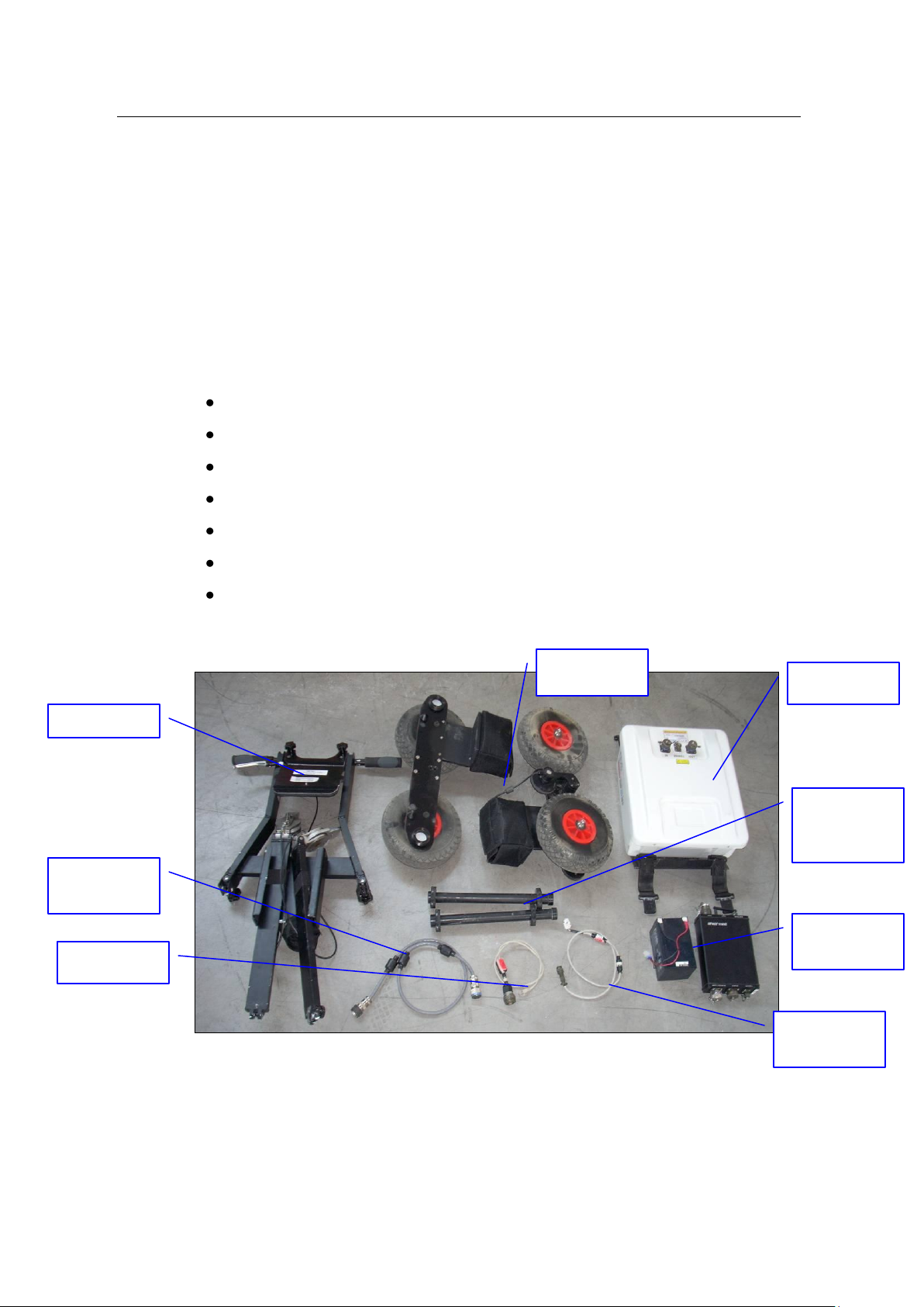
Rudder
Wheel
Antenna
Cable
LAN Cable
Battery
Cable
Antenna
Battery and
DAD
Junction
Pipes
1. HARDWARE EQUIPMENT OF THE HI-MOD AND DUALF-400-900
SYSTEMS
Hi-MOD and DUALF-400-900 systems offers you the possibility to choose up to
four different equipments, matching the number of antennas you want to use. This
handbook shows you the equipment you will receive and guides you through the
configuration of your hardware.
One antenna equipment and configuration (Fig. 1-1) shows you the equipment you
will receive for your mono antenna configuration. The equipment is composed of:
A Rudder
Two Wheel frames
Two Junction pipes
An Antenna and its cable
A Battery and its cable
DAD control unit
LAN cable
Fig. 1-1 – Equipment provided for mono antenna configuration
1.1.1 Assemblage instructions
14 / 45
 Loading...