

Page 1

IDS X-Series v2.7
Change Guide
Introduction
With X-Series v2.7 comes the new Xwave 2. The latest in bi-directional wireless technology that
will ensure your detectors are properly supervised.
Xwave2
The IDS X-Series Bi-directional Xwave2 Hub offers an additional 16 wireless supervised zones
and two programmable outputs. The hub can also learn up to 16 Xwave2 Bi-directional remote
transmitters. It is wired to the X-Series panel in the same way as all other peripheral devices, on
the keypad bus.
1. Installation
Xwave2 works on the IDS X-Series panels, versions 2.7 and above.
1.1. Addressing
To address the Xwave2 Hub, set the dipswitches as per the table below. Depending on what
address is used on the Hub will determine the zone numbers it uses.
Note: The unit must be powered down when selecting the unit’s address.
Binary value on switch
Hub zones
Dipswitch 1 up
1 -16
Dipswitch 2 up
17 - 32
Dipswitches 1 + 2 up
33 – 48
Dipswitch 3 up
49 - 64
Dipswitch 6 up
3 second button panic disabled
Page 2

1.2. Xwave
2
and Other Wireless Expanders
The Xwave2 Hub can work in conjunction with Xwave/Duevi. You can either have the Xwave
2
operating with a different address to an Xwave/Duevi Expander using a different zone range or,
if needed, with the same address as an Xwave/Duevi Expander in which case it will share the
zone range.
Remember you can only have 1 wireless device learnt to a zone, so if you have a Duevi
detector learnt to zone 4, you cannot learn an Xwave2 detector to zone 4. You will have to use
another zone number or delete the Duevi detector in zone 4.
1.3. Xwave
2
Hub Outputs
The Xwave2 Hub has two onboard programmable outputs. The address of these outputs are
based on the hubs ID.
Binary value on switch
PGM Address
Dipswitch 1 up
6 + 7
Dipswitch 2 up
8 + 9
Dipswitches 1 + 2 up
10 + 11
Dipswitch 3 up
12 + 13
1.4. Xwave
2
Hub LEDs
There are 4 LEDs on the board marked “BEACON”, “NETWORK”, “TROUBLE” and “ALERT”.
BEACON: LED will flash when transmitting information.
NETWORK: LED indicates the bi-directional networks information. The LED
will be ON in normal operation with no errors. If there are errors
it will start pulsing the error number.
TROUBLE: LED indicates troubles with the Hubs connection to the X-
Series bus. The LED will be OFF if there are no troubles. If
there are errors it will start pulsing the error number.
ALERT: LED will pulse to indicate a message is being received.
1.5. Xwave
2
Hub Trouble Display
The Xwave2 Hub will indicate any errors by pulsing the Network or Trouble LED. The LED will
pulse according to the error number shown below.
Network Pulse Number:
Pulse
Error
Description
1
Learn Mode
The hub is in learn mode to add new devices to its network.
2
Remote Panic
A panic has been received from a remote transmitter.
3
Low Detector
Battery
A detector has reported that its battery needs to be replaced.
4
Detector Tamper
A device has reported a tamper.
5
Supervision Loss
A device has not checked in at the required time.
6
Low Signal
Strength
A device on the network has a very low signal strength.
7
Signal Jam
A signal at the same frequency has been detected and could
interfere with signals to and from detectors.
Page 3

Trouble Pulse Number:
Pulse
Error
Description
1
Dead Keypad Bus
There is no activity on the bus.
2
Not Registered
The hub has not been able or is waiting for the X-Series panel to
be registered.
3
Not Receiving
Messages
The hub is registered on the bus but is not receiving messages.
4
Invalid Dipswitches
Dipswitches are set to an unrecognised setting.
1.6. Defaulting
If an Xwave2 Hub has been registered to a panel it would have received a unique network ID
and to remove the hub and attached it to a different X-Series panel it must be defaulted.
To default the Xwave2 Hub:
1. Remove all power
2. Put all dipswitches ON
3. Power the unit up and wait three seconds
4. Power the unit down
2. Location 260
All Xwave2 programming is done in location 260. Here you can learn a detector, delete a
detector and change a detectors configuration.
2.1. Learning an Xwave
2
Detector (Sub Location 1)
If a detector is not learnt to a hub it will send out join requests every 20 seconds.
There are two ways you can learn an Xwave2 detector:
1. Go to Location 260 Sub Location 1, select the zone number and type in the serial
number of the detector.
If the detectors serial code is listed in the hub then the hub will learn the detector once it
receives a join request from that detector.
2. Go to Location 260 Sub Location 1, select the zone number and release the tamper of
the detector.
A hub will only learn a detector if it receives the detectors join request with a tamper signal. If
you have multiple defaulted detectors with their covers off then the hub will learn the first signal
it gets. NB: Only have 1 defaulted detector tampered at a time.
There will be a slight delay when moving a detector from one hub to another. You can learn a
learned detector to another hub by deleting the serial code from the existing hubs zone and
then entering the serial code into the new hubs zone. The detector can take up to 3 mins to
default once removed from the first hub, at which point it will join the new hub it is learned to.
Page 4
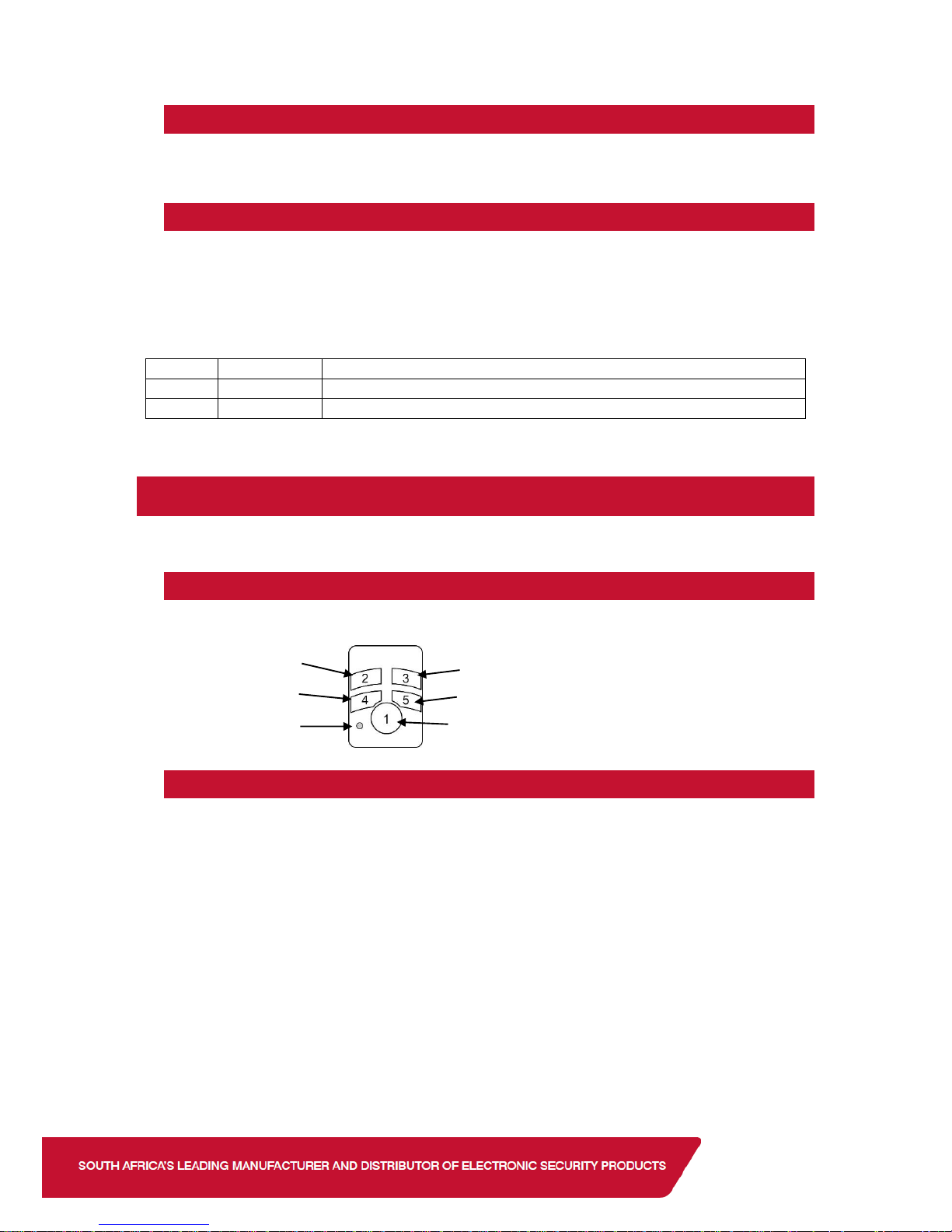
Arm/Disarm
Feedback LED
Unassigned
2.2. Deleting an Xwave
2
Detector
To delete a detector go to location 260 sub location 2, select the zone and press * to delete.
The detector will default itself within 3 minutes allowing it to be learned to another hub.
2.3. Xwave
2
Configuration Settings
Due to the intelligence of Xwave2 you can now change the detectors configuration settings,
LED and Pulse count, from the X-Series panel.
Go to location 260 sub location 5, select the zone and enable/disable the bitmaps according to
your needs. See bitmap values below.
LED
Default
Action
1
ON
Detector LED
2
ON
On for a pulse count of 2 and Off for a pulse count of 4.
3. Xwave
2
Remotes
The user menu is used to add/edit/delete remotes.
3.1. Remote Transmitter
Each remote transmitter has five buttons to control the alarm panel or query its status.
3.2. Defaulting
If the remote transmitter was learnt to a different bi-directional installation it must be defaulted
before joining a new installation.
Defaulting procedure 1:
1. Remove the battery from the unit
2. Hold down button 1
3. Insert the battery while holding button 1
4. Release button 1.
Defaulting procedure 2:
1. Press and hold a remote transmitter button until it stops sending panics (Red Led
comes on) when out of range or if the bi-directional hub is off.
Function Button
Unassigned
Stay Arm
Page 5

3.3. Adding the Remote Transmitter to a User code
To add a bi-directional Xwave2 remote transmitter to a user code.
1. Enter the Master User Menu
2. Scroll to menu [Add Bidir Remote] or enter [1][6][*]
3. Enter the Hub that you are teaching the remote too
4. Enter the user code that will be paired with the remote
5. Press any remote button until the remotes ID is displayed
6. Press [*] to confirm
7. Enter the next user code if more than one remote is to be learnt or [#] to exit.
3.4. Allocating Remote Transmitter Buttons
To change the button functions:
1. Enter the Master User Menu
2. Scroll to menu [Edit BD Buttons] or enter [1][7][*]
3. Enter the Hub that the remote belongs too
4. Enter the user code that was paired with the remote
5. Scroll through the buttons until the button to be changed and press [*]
6. Scroll through until the function required and press [*] to confirm
7. Enter the parameter followed by [*] to confirm (The parameter will be the partition
number or the output number.)
See a list of functions below:
Function
Parameter
Description
Unassigned
--
No function allocated.
Arm
Partition
Number
Will only arm the partition allocated to button and user code.
Disarm
Partition
Number
Will only disarm the partition allocated to button and user code.
Arm/Disarm
Partition
Number
Will only arm or disarm the partition allocated to the user code.
Global Arm
Will only arm the partitions allocated to the user code.
Global Disarm
Will only disarm the partitions allocated to the user code.
Global
Arm/Disarm
Will only arm or disarm the partitions allocated to the user code.
Stay Arm
Partition
Number
Will arm the allocated partition in the current/last used stay profile.
Stay Arm Prof1
Partition
Number
Will arm the allocated partition in stay profile 1 and then allow you to scroll
to the next available profile if one is configured.
Stay Arm Prof2
Partition
Number
Will arm the allocated partition in stay profile 2 and then allow you to scroll
to the next available profile if one is configured.
Stay Arm Prof3
Partition
Number
Will arm the allocated partition in stay profile 3 and then allow you to scroll
to the next available profile if one is configured.
Stay Arm Prof4
Partition
Number
Will arm the allocated partition in stay profile 4 and then allow you to scroll
to the next available profile if one is configured.
Stay & Go
Partition
Number
Will arm the allocated partition in the current/last used stay profile.
Stay & Go
Prof1
Partition
Number
Will arm the allocated partition in stay & Go in stay profile 1 and then allow
you to scroll to the next available profile if one is configured.
Stay & Go
Prof2
Partition
Number
Will arm the allocated partition in stay & Go in stay profile 2 and then allow
you to scroll to the next available profile if one is configured.
Page 6

Function
Parameter
Description
Stay & Go
Prof3
Partition
Number
Will arm the allocated partition in stay & Go in stay profile 3 and then allow
you to scroll to the next available profile if one is configured.
Stay & Go
Prof4
Partition
Number
Will arm the allocated partition in stay & Go in stay profile 4 and then allow
you to scroll to the next available profile if one is configured.
Duress Disarm
Partition
Number
Will disarm the allocated partition and cause a duress condition in the
alarm system and if configured the alarm will transmit the duress signal to
the security company.
Panic
Partition
Will cause the alarm to go into a panic condition and if configured the
alarm will transmit the panic signal to the security company.
Medical
Partition
Will cause the alarm to send a medical alert signal to the security
company if configured.
Fire
Partition
Will cause the alarm to send a fire alert signal to the security company if
configured.
PGM Low
PGM
Number
Will trigger the specified programmable output depending on the type of
output, to switch from 12V to 0V or from a closed state to an open state.
PGM High
PGM
Number
Will trigger the specified programmable output depending on the type of
output, to switch from 0V to 12V or from an open state to a closed state.
PGM PulseL
PGM
Number
Will trigger the specified programmable output depending on the type of
output, to switch from 12V to 0V and back to 12V or from a closed state to
an open state and back to a closed state. (Pulse length setup under the
output properties.)
PGM PulseH
PGM
Number
Will trigger the specified programmable output depending on the type of
output, to switch from 0V to 12V and back to 0V or from an open state to
a closed state and back to an open state. (Pulse length setup under the
output properties.)
PGM Toggle
PGM
Number
Will trigger the specified programmable output depending on the type of
output, to the opposite of its current state. If at 0v will set to 12v, if at 12v
will set to 0v. Toggling the PGM.
3.5. Deleting Remote Transmitters
If a remote transmitter is lost or no longer used follow the following steps to delete the remote
transmitter from the system.
1. Enter the Master User Menu
2. Scroll to menu [Delete BD Remote] or enter [1][8][*]
3. Enter the Hub that the remote belongs too
4. Enter the user code that was paired with the remote
3.6. Remote Transmitter LED
The remote transmitter has bi-directional communication with the X-Series alarm panel and will
display different information by changing the colour of the LED and flashing a number of times.
The remote transmitter will respond with the status when you use a button or you can query the
alarm panel and get feedback e.g. armed or disarmed, current stay profile, outputs.
To query status:
1. Press the function button. (Button 1)
2. Then press the button that is allocated to the function that is being queried
3. The LED will indicate the status.
Page 7

Example to query the arm status of the alarm using the default button assignments:
Press button 1 (Function button) then button 3 (Arm/Disarm button). The led will flash white
indicating transmitting message then blue if the alarm is ready to arm, red if armed or flash red
if armed but a violation has occurred.
Colour
Description
Flash
White
Transmitting signal to the Xwave2 Hub
Alarm Status
Blue
Ready to arm
Yellow
Not ready to arm
Red
Away Armed
Long
Stay Armed in profile 1
1 short
Stay Armed in profile 2
2 short
Stay Armed in profile 3
3 short
Stay Armed in profile 4
4 short
Alarm has been triggered
15 flashes
Output Status
Blue
Output is Off
Red
Output is On
4. Walk Test
The user menu is used to put the detectors in ‘Walk Test’.
Walk test mode will put certain capable devices into walk test mode from the X-Series keypad.
Once in walk test mode the device will trigger continuously when an object has been detected
and the LED will come on to indicate the detection.
To enter devices into walk test mode:
1. Enter the Master User Menu
2. Scroll to [Walk Test] menu or enter [1][9][*]
3. Enter the partition whose devices you want to walk test
4. Enter the number of minutes the walk test must stay active, 1 to 15 minutes. The system
will automatically exit walk test mode once the time entered expires.
5. I/O Module
The Xwave2 I/O Module is a wireless device with two physical zone inputs and one output.
The module requires 12vDC power. You can wire two wired detectors into the zone inputs and
it will transmit as a wireless device. The module learns to the hub in the same way as any other
detector, however:
1. If you learn by tamper the module will learn its first input into the selected zone and the
second input will automatically learn into the following zone.
2. If you learn by serial number the module will learn the first input into the selected zone
and the second zone will be disabled.
Page 8

The module has one programmable output, the address of the output is based on what zone
the I/O Module is learned to.
Zone Range
I/O Module PGM
Address
1 – 4
42
5 – 8
43
9 – 12
44
13 – 16
45
17 – 20
46
21 – 24
47
25 – 28
48
29 – 32
49
33 – 36
50
37 – 40
51
41 – 44
52
45 – 48
53
49 – 52
54
53 – 56
55
57 – 60
56
61 – 64
57
6. Other New Features
6.1. Location 56 Dialler Retry Wait Time
Location 56 has been added to X-Series 2.7 communication settings. This allows you to set the
time the dialler waits before trying to dial again in the event it failed to report to the basestation.
6.2. Location 251-258 Keypad Options
Sub-locations 7 and 8 have been added to the keypad options in locations 251-258.
Sub-location 7 (Buzzer follows Siren) will enable the keypads buzzer to sound when the siren
sounds.
Sub-location 8 (Global Chime) will set the keypad to chime for all chime zones in all partitions.
6.3. User Code or User Slot
In the User Menu you can now edit all user properties using either the user code or the user
slot, including remote programming. This allows you to edit user properties without knowing the
users’ code.
 Loading...