

Page 1
IDS 1632 Installer Manual 700-256-02K Issued September 2009
1
Page 2

IDS 1632 Installer Manual 700-256-02K Issued September 2009
2
Page 3

IDS 1632 Installer Manual 700-256-02K Issued September 2009
3
Contents
1. Introduction to the IDS 1632 --------------------------------------------------------------------- 8
1.1 Features of the IDS 1632 --------------------------------------------------------------------------- 8
2. Installation and Wiring --------------------------------------------------------------------------- 10
2.1 Additional Technical Data ------------------------------------------------------------------------ 11
2.2 End-of-Line Resistors------------------------------------------------------------------------------ 11
2.3 Box Tamper Input ------------------------------------------------------------------------------ 13
2.4 Installing an Expander Module ------------------------------------------------------------------ 13
2.5 Connecting the Telephone Communicator --------------------------------------------------- 13
2.6 Programmable Outputs --------------------------------------------------------------------------- 13
2.7 Key-Switch or Remote Control Unit ------------------------------------------------------------ 13
2.8 IDS Remote Receiver ------------------------------------------------------------------------------ 14
2.9 Radio Transmitter Connection ------------------------------------------------------------------- 14
3. Hardware Reset Switch -------------------------------------------------------------------------- 14
4. Enrolling Keypads and Other Devices ------------------------------------------------------ 14
4.1 Replacing a Faulty Keypad/Device ------------------------------------------------------------- 15
4.2 Defaulting Keypads ------------------------------------------------------------------------------ 15
5. Event Log--------------------------------------------------------------------------------------------16
6. Download Code------------------------------------------------------------------------------------16
6.1 Programming the Panel --------------------------------------------------------------------------- 16
6.2 Location Values--------------------------------------------------------------------------------------16
7. Programming the Panel -------------------------------------------------------------------------- 17
7.1 Entering Program Mode -------------------------------------------------------------------------- 18
7.2 Programming Standard Locations ------------------------------------------------------------- 18
7.3 Programming Extended Locations ------------------------------------------------------------- 18
7.4 Programming a Bitmapped Location ---------------------------------------------------------- 19
7.5 Incorrect Data Entries ----------------------------------------------------------------------------- 19
7.6 Programming Location Summary -------------------------------------------------------------- 20
7.6.1 Zone Options ---------------------------------------------------------------------------------------- 20
7.6.2. System Options ------------------------------------------------------------------------------------- 24
8. System Reporting Codes (4 x 2 and Domestic) ----------------------------------------- 30
9. System Programmable Outputs --------------------------------------------------------------- 32
10. System Clock Options ---------------------------------------------------------------------------- 34
11. Communicator Options -------------------------------------------------------------------------- 36
11.1 Programming Telephone Numbers ------------------------------------------------------------ 43
11.2 Telephone Number Storage Locations -------------------------------------------------------- 44
11.3 Download Options ------------------------------------------------------------------------------ 44
11.4 Cellphone Operation Settings ------------------------------------------------------------------- 45
12. Partition Setup-------------------------------------------------------------------------------------46
13. User Options---------------------------------------------------------------------------------------52
Page 4

IDS 1632 Installer Manual 700-256-02K Issued September 2009
4
14. Programmable Output Options ---------------------------------------------------------------- 56
15. Keypad Options------------------------------------------------------------------------------------58
16. Installer Options-----------------------------------------------------------------------------------59
Index of Programming Locations --------------------------------------------------------------------- 60
Index -----------------------------------------------------------------------------------------------------------63
Page 5

IDS 1632 Installer Manual 700-256-02K Issued September 2009
5
Figures
Figure 1 : Connection Diagram without Tamper per Zone ----------------------------------- 10
Figure 2 : Tamper by Zone Connection ------------------------------------------------------------- 11
Figure 3 : Zone Doubling Connection --------------------------------------------------------------- 12
Figure 4 : Resistors (Tamper per Zone or Zone Doubling) ---------------------------------- 12
Figure 5 : Programmable Output Configuration ------------------------------------------------- 13
Figure 6 : Fire Detect Output Sequence ------------------------------------------------------------ 34
Tables
Table 1 : Values Represented by each Zone LED ----------------------------------------------- 17
Table 2 : Hexadecimal Value --------------------------------------------------------------------------- 18
Table 3 : Location / Zone Defaults -------------------------------------------------------------------- 20
Table 4 : Programmable Zone Types ---------------------------------------------------------------- 21
Table 5 : Programmable Output Numbering ------------------------------------------------------ 32
Table 6 : Output Actions ------------------------------------------------------------------------------ 32
Table 7 : Event Driven Programmable Outputs -------------------------------------------------- 33
Table 8 : Function Driven Programmable Outputs ---------------------------------------------- 33
Table 9 : Value for Day of the Week------------------------------------------------------------------ 35
Table 10 : Standard Contact ID Reporting Codes ---------------------------------------------- 39
Table 11 : Standard SIA Reporting Codes --------------------------------------------------------- 40
Table 12 : User Codes ------------------------------------------------------------------------------ 52
Page 6
IDS 1632 Installer Manual 700-256-02K Issued September 2009
6
Page 7
IDS 1632 Installer Manual 700-256-02K Issued September 2009
7
Page 8

IDS 1632 Installer Manual 700-256-02K Issued September 2009
8
1. Introduction to the IDS 1632
The IDS 1632 is a versatile, microprocessor based sixteen zone Alarm Panel. It has eight partitions and
can be expanded to thirty two zones. Most features are optional and may be programmed either directly
through the keypads or via the telephone system, using the IDS download software and appropriate
modem.
There are sixteen programmable burglary zones, a dedicated panic zone, monitored siren output,
auxiliary power outputs and eight programmable outputs that may be programmed to perform various
trigger/switching functions.
The IDS 1632 also interfaces to a Voice Module, GPRS module and may be controlled remotely via DTMF
telephone keypad.
The voice module makes it possible to have the Alarm Panel call a user’s telephone number and report in
plain English. The user may also access the Panel, using DTMF keystrokes and be guided through a
menu system by English Voice Prompts.
IDS GSM Communicators (GPRS modules) are available in two versions:
The SMS Communicator allows clients to control and program their Alarm Panels via a cellphone
– it also allows up to 5 cellphones to receive SMS event reporting.
Outstation Communicators connect the clients’ Alarm Panels to the Security Company Control
Room via a third party Communications Watchdog Company (which monitors signal strength
levels and ensures that reports are acknowledged.) Alarm Companies are also able to
program/upload/download the clients’ IDS 1632 Alarm Panels by means of an IDS GSM Base
Station Communicator and the associated Download Software.
For correct operation, the IDS 1632 must be used in conjunction with the specified transformer/battery
combination and appropriate peripheral sensors and signalling devices.
1.1 Features of the IDS 1632
RS485 keypad bus supports two eight-zone expander modules, one IDS remote receiver, up to
16 keypads and an IDS GSM Communicator.
Sixteen programmable, end-of-line supervised zone inputs.
Expandable to thirty two zones via keypad zones, zone expander modules, zone doubling or
wireless expansion.
8 partitions
Optional tamper reporting per zone using double end-of-line resistors (12K and 4K7)
Fully programmable digital telephone communicator that supports most industry standard
formats.
Eight programmable outputs on Alarm Panel. Expandable to twelve when using Wired Zone
Expander module.
Non-volatile EEPROM memory retains all program and event log data in the event of a total
power failure.
Event log, date and time stamped (approximately 700 events – exact number of events is
dependant on the timing of the events).
Programmable loop response time
Up and downloadable using IDS Windows based software, either directly via RS 232 or remotely
using a modem.
Page 9

IDS 1632 Installer Manual 700-256-02K Issued September 2009
9
Excellent protection against lightning (provided by specialised “zap tracking” and transient
suppressors).
Auto arm/disarm capability per partition and by day of the week. The panel can be programmed
to arm/disarm at a pre-determined time.
Fax defeat/answering machine override
Dual reporting provides for duplicated reporting to two independent central base stations – or
one base station and a cellphone.
Dynamic battery self test
Low battery cut out circuit
Support for secure dial-in functionality using any DTMF phone.
Optional voice module for voiced reporting and DTMF, voice-prompted remote-controlled menu.
GPRS SMS reporting and alarm control functionality via cellphone (when a GSM Communicator is
installed).
Page 10

IDS 1632 Installer Manual 700-256-02K Issued September 2009
10
Line I n
Line
Line
Phone
Siren
Radio
+
+
Prog ram ma bl e Out put s
1
2
3
4
5
6
7
8
S
Radio Transmitter /
Communicator Power
Radio Transmitter or Communicator
Hardware
Reset Switch
Battery 4A
Auxiliary Power 12 Volt
+
+
+
+
D-
D+
Keypad
Zone Zone Zone Zone Zone
Zone Zone
1
2
3
4
5
6
7
8
9
10
11
12
13
14
15
16
ZoneZone
P
3K3
3K3
3K3
Connect as required with
a resistor in unused zones
Connect as re quired wi th
a resi stor in unu se d zones
-
-
3K3
3K3
Aux 1A
Siren 4 A
Box
Tamper
Direct Dowload
Port
16 V AC
AC Mai n s
D -
D +
GND
+12V
123
4
5 6
7 8
9
0*#
P
M
F
Pgm
Zone
Panic
Button
N/O
Doo r LED
2. Installation and Wiring
Refer to Figure 1: Connection Diagram, and familiarise yourself with the following sections.
Figure 1 : Connection Diagram without Tamper per Zone
Page 11

IDS 1632 Installer Manual 700-256-02K Issued September 2009
11
2.1 Additional Technical Data
A suitable transformer with an output voltage of 16 volts AC ±10% with a 32VA minimum rating
must be used
A 12V sealed lead acid battery with a minimum capacity of 7AH must be used. The back up
period after mains failure will depend on the number of keypads, sensors and peripheral devices
connected to the system.
The panel can supply a total continuous current of 750mA to peripheral devices such as keypads,
remotes, receivers, passives etc.
Connect a 12 volt self-driven siren or piezo siren [not a horn speaker] to the siren output.
2.2 End-of-Line Resistors
(Including Tamper by Zone / Zone Doubling)
All zones must be end-of-line supervised.
Any unused zones must be terminated with a 3K3 resistor. The end of line resistor must be
placed inside or as close to the sensor as possible.
If neither zone doubling nor tamper by zone are required the 3K3 resistor must be used.
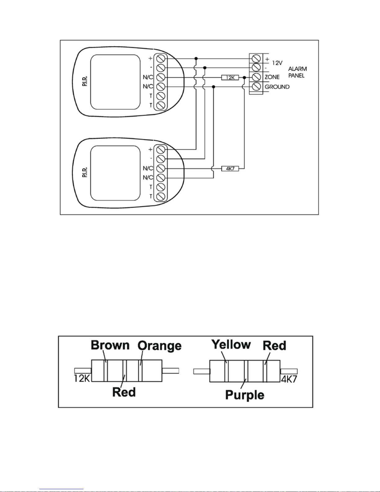
For zone doubling or tamper per zone, the 4K7 and 12K end-of- line resistors must be connected
as per Figures 2 and 3.
Figure 2 : Tamper by Zone Connection
Tamper operation is as follows:
If the panel is unarmed and a tamper condition occurs, the siren will not sound but a tamper
condition will be reported.
If the panel is armed and a tamper condition occurs an audible alarm will register and a tamper
condition AND zone violation will be reported.
Panic zones always register panic and tamper conditions.
The colour codes for the 12K and 4K7 resistors are as per in Figure 4.
Page 12
IDS 1632 Installer Manual 700-256-02K Issued September 2009
12
Figure 3 : Zone Doubling Connection
The following limitations apply to zone doubling:
1. Only normally closed contacts (n/c) may be used.
2. If the zone input to the panel is short or open circuited at the panel, both the zone and its double
will be violated.
3. If the 12K resistor is “open circuited” the primary zone will indicate a violation i.e. assuming zone
8 is doubled in this case zone 8 will be indicated as violated.
4. If the 4K7 resistor is “open circuited” the secondary zone will indicate a violation i.e. assuming the
example in 3 above zone 16 would indicate the violation.
5. The colour codes for the 4K7 and 12K resistors are shown in Figure 4.
Figure 4 : Resistors (Tamper per Zone or Zone Doubling)
Page 13
IDS 1632 Installer Manual 700-256-02K Issued September 2009
13
2.3 Box Tamper Input
The box tamper input does not require an end-of-line resistor and requires a normally closed contact.
2.4 Installing an Expander Module
When installing an expander module refer to the document supplied with the module. Note that only one
or two (8-zone) expansion modules may be added to the IDS 1632 Alarm Panel.
2.5 Connecting the Telephone Communicator
Refer to Figure 1. Connection Diagram (Page 10).
For optimum lightning protection, connect a low impedance earth to the communicator earth input.
Always connect the telephone communicator in line seizure mode and never in parallel with the
telephone. Ensure the telephone receiver is connected to the communicator terminals marked “phone”
and the incoming line to the terminals marked “line”.
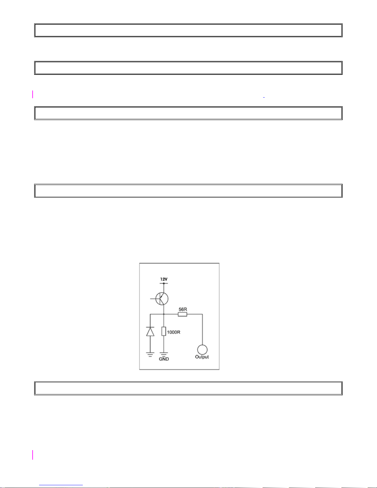
2.6 Programmable Outputs
A relay board must be used when any device requiring a high current is connected to a programmable
output. The programmable output circuitry consists of a 12 volt source with a 56 Ω series resistor. Current
sink is via a 1 000 Ωresistor to negative. For information purposes, the output circuitry for a single output
is shown in Figure 5.
Figure 5 : Programmable Output Configuration
2.7 Key-Switch or Remote Control Unit
A momentary key-switch or non-latching remote control receiver may be connected to any zone to allow
remote arm/disarm and remote panic capability.
When using a key-switch or remote control unit a 3K3 resistor must be connected between the
zone input and ground.
Use only a spring-loaded momentary key-switch or non-latching remote control unit.
Page 14

IDS 1632 Installer Manual 700-256-02K Issued September 2009
14
2.8 IDS Remote Receiver
An IDS Remote Receiver (P/N 860-06-0003) may be connected to the keypad bus. Using this facility
allows remote arming and disarming of the panel while providing user identification for a maximum of 238
remotes.
2.9 Radio Transmitter Connection
When connecting a radio transmitter, use the TX terminal provided on the PCB to supply power to the
transmitter. (See Figure 1) This output is protected by the 4 Amp battery fuse.
3. Hardware Reset Switch
Should the need arise to return the panel to factory default, use the hardware reset switch (see Figure 1).
The panel may be defaulted as follows:
Remove both battery and AC power from the panel. While depressing the reset switch reapply power to
the panel by either connecting the battery or the AC power. Release the reset switch approximately 2
seconds after reapplying the power. Factory default values will now be restored to all locations and all
attached keypad IDs will be defaulted. A default event will be logged and the existing event log will NOT
be erased.
NOTE:
Once the reset switch has been disabled by programming a 10 into location 444, it will no longer be
possible to default the panel using the reset switch. The panel can only be defaulted if a valid installer
code is entered and a value of [0] is entered into location 0.
4. Enrolling Keypads and Other Devices
A new panel supplied from the factory will have factory default values in all locations (as indicated
throughout this manual). Similarly new keypads will have no ID assigned to them. It is however good
practice to default the system by using the reset switch prior to commencement of programming. This will
ensure that the above is true and that no factory test values remain.
The keypad/s attached to a system as defaulted above will have no ID and will therefore not
communicate with the panel. This is indicated by all keypad LED’s flashing simultaneously.
In order to enrol a keypad (thereby giving the keypad an ID) press the [#] key of the keypad
you wish to enrol. The enrolled keypad will now indicate the alarm status. Repeat this process with the
remaining keypads where more than 1 keypad is used.
The first keypad enrolled will have an ID of 1, the second enrolled will have an ID of 2, the third an ID of 3
etc. A maximum of 16 keypads may be used.
NOTE:
If the keypad zone is to be used, consideration must be given to the sequence in which keypads are
enrolled as this affects the LED zone designation. The keypad 1 will contain zone 32, keypad 2 will
contain zone 31 etc.
Fitting zone expanders will introduce zones that use these same addresses – to make use of the zones
on the expanders, the corresponding keypad zones will need to have resistors fitted. Use can be made of
the keypad zone OR the expanded zone – and NOT both simultaneously.
Page 15

IDS 1632 Installer Manual 700-256-02K Issued September 2009
15
Additional Devices
To enrol other devices (IDS Remote Receivers or Zone Expanders); consult the installation instructions for
those devices. The IDS 1632 Alarm Panel can accept up to two eight-zone expander modules, and an
IDS Remote Receiver.
4.1 Replacing a Faulty Keypad/Device
NOTE:
Should a faulty keypad be REPLACED with another keypad, the following applies:
1. Disconnect ONLY the faulty keypad.
2. Program a value 4 into location zero to free up all vacant addresses.
3. Connect the replacement keypad and enrol it - by pressing [#] – it will now be enrolled in the first
available address, which should now be the address just freed up in step 2.
NOTE:
If other devices (keypads) are disconnected (or faulty), at the time of performing step 2, their addresses
will also be freed. Any new devices being enrolled will automatically be allocated addresses beginning
from the lowest free address. This can cause devices to be associated with the wrong
addresses/partitions. The resultant communications attempts made to the wrong addresses can result in
sluggish system behaviour. Operation will become confusing.
Check
After enrolling a keypad, go to location 446 to check the keypad’s ID (which is a number that
corresponds to the order that the keypads were enrolled). If the keypad ID is incorrect (3
rd
keypad has ID
= 2, for example), then this must be rectified for the system is to operate correctly.
Solution
If the system is complex and has developed a keypad allocation problem, it is recommended that all
keypads are defaulted and registered “from scratch”, as it were, in the correct, required sequence.
To re-enrol a Zone Expander, or an IDS Remote Receiver, consult the installation instructions for the
relevant device.
4.2 Defaulting Keypads
To default the ID of an individual keypad:
Power off, Hold [1] & [3], Restore power, Release [1] & [3]
1. Remove power to the keypad (or the whole panel if easier). Whilst holding down the [1] and [3]
keys restore the power to the keypad.
2. All the keypad LED’s will flash simultaneously indicating that the keypad has now been de-
registered.
3. The ID of any (correctly registered) keypad can be interrogated by viewing the data in location
446 from the keypad of interest.
4. Wait for five seconds and then press the hash [#] key to allocate a new ID to the defaulted
keypad. Keypad IDs are allocated incrementally.
Page 16

IDS 1632 Installer Manual 700-256-02K Issued September 2009
16
To default the ID of ALL keypads:
Programming a value of [3] into location [0] causes ALL keypads to be defaulted.
[INSTALLER CODE] [*] [0] [*] [3] [*]
On pressing the final [*], wait a few seconds and ALL the keypads will begin flashing. (Do NOT press [#]
at the end of this sequence, unless you wish the keypad you are using to be registered in the first
address)
Re-enrol all keypads by pressing [#] on each keypad – in the CORRECT sequence to ensure that
keypad zone and partition allocation is as required by the user.
5. Event Log
A comprehensive log of the 700 most recent events is retained in the non-volatile EEPROM. The log may
be retrieved using the up/ download software. Alternatively, it can be viewed using an LCD keypad. (See
LCD Keypad Manual)
NOTE:
The exact number of events that can be stored is dependant on the event timing, which means it can vary
between 300 and 1000 events, practically averaging out to be of the order of 500 events.
6. Download Code
The download code (in conjunction with the installer code) is required for download access. The default
download code is 9999. Using the downloading software, it is possible to program a location that will
either allow or disallow defaulting of the download code.
This location is only accessible using the download software. If the panel is defaulted, the
download code will revert back to 9999. A value of [1] [0] programmed into this location will prevent the
download code from being defaulted when defaulting the panel.
6.1 Programming the Panel
The panel can be programmed either via a keypad or via the up/ download software. Programming the
panel by means of an LED keypad is explained below:
NOTE:
Before commencing programming, it is advisable to read the Installer Manual thoroughly.
6.2 Location Values
All values within a program location will be displayed by the zone indicators in binary coded decimal
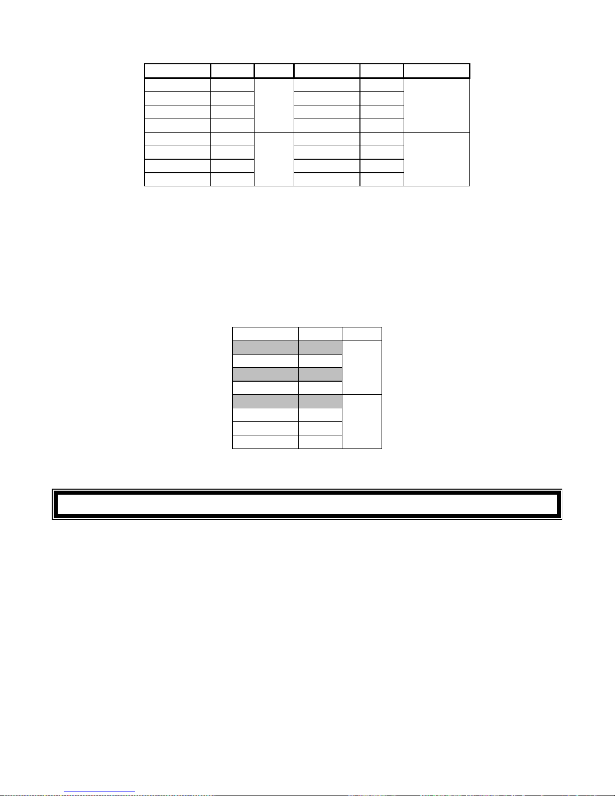
format i.e. zone indicators 1-4 indicate units (1’s) and zone indicator 5-8 indicate tens (10’s), and so on.
To read a binary value on the keypad sum the values represented by each on LED as shown in Table 1:
Page 17
IDS 1632 Installer Manual 700-256-02K Issued September 2009
17
Table 1 : Values Represented by each Zone LED
Zone LED
Value
Digit
Zone LED
Value
Digit
Zone 1 1
Units
Zone 9 1
Hundreds
Zone 2 2 Zone 10 2
Zone 3 4 Zone 11 4
Zone 4 8 Zone 12 8
Zone 5 1
Tens
Zone 13 1
Thousands
Zone 6 2 Zone 14 2
Zone 7 4 Zone 15 4
Zone 8
8
Zone 16
8
Example:
Assume the following zone indicators are on:
Zone 1, Zone 3 and Zone 5.
Units are represented by the sum of Zone 1 and Zone 3 (i.e. 1 + 4) and tens of units are represented by
the value of Zone 5 (i.e. 1)
Thus, the value indicated by the lit LED will be shown below.
Zone LED
Value
Digit
Zone 1 1
Units
Zone 2 2
Zone 3 4
Zone 4
4
Zone 5 1
Tens
Zone 6 2
Zone 7 4
Zone 8 8
Therefore, the displayed value is 15.
7. Programming the Panel
For all programming procedures, the [*] star key functions as the <ENTER> key and the [#] hash key
functions as a <CLEAR> or an <EXIT> program key.
Invalid data entries are indicated by means of an error beep consisting of 3 short beeps of the
keypad buzzer.
There are two location categories:
Standard locations which are single tiered and do not contain any sub-locations.
Extended locations that are double tiered and have sub-locations.
Both standard and extended locations may contain further subcategories referred to as bitmapped
locations.
For both main categories, clear visual keypad prompts are provided which aid the
programming process.
Page 18
IDS 1632 Installer Manual 700-256-02K Issued September 2009
18
To read the data stored in multi-digit locations (e.g. a telephone number, account codes etc.),
enter the location. Upon initial entry into the location, the first digit will be displayed by the zone
indicators. Pressing the [Panic] key will cause the next digit within the location to be displayed.
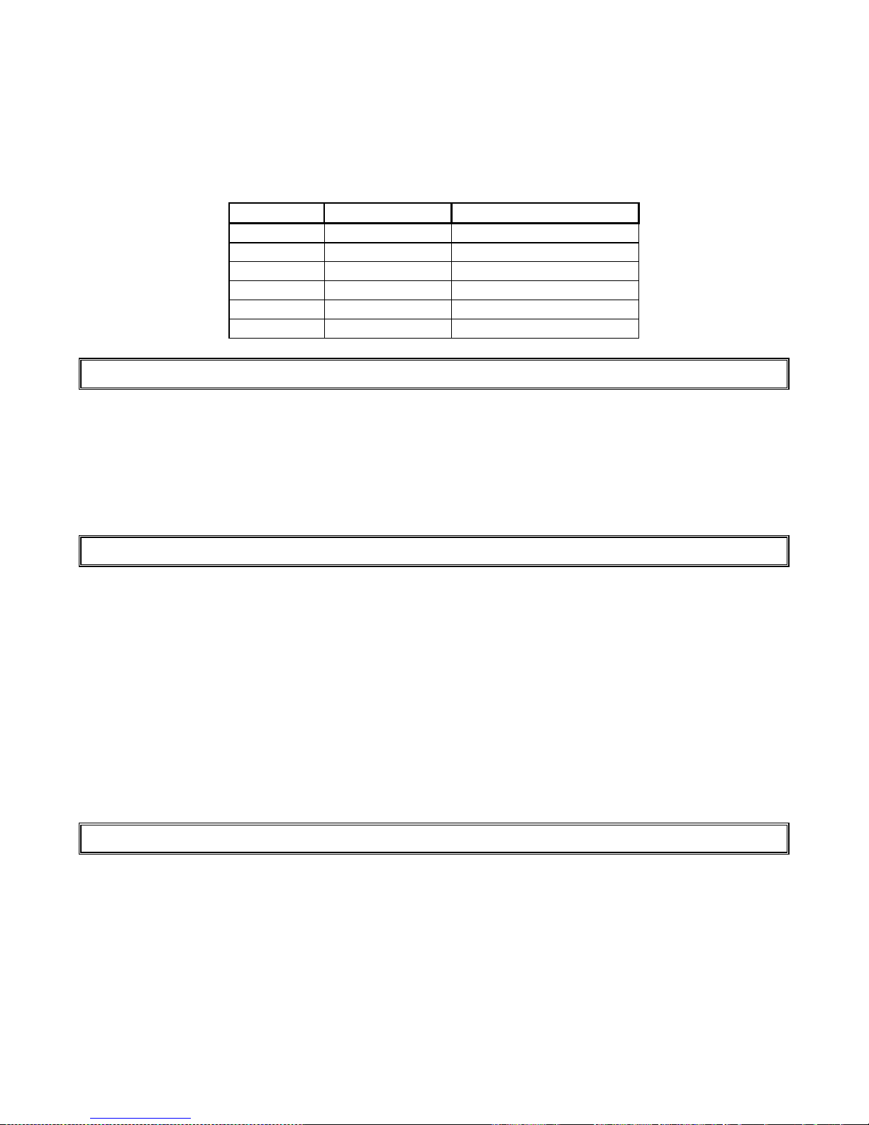
Where a hexadecimal number must be programmed, use the [MODE] key as per Table 2 below:
Table 2 : Hexadecimal Value
Hex Value
Decimal Value
Key Strokes
A 10 [MODE] key then [0] key
B 11 [MODE] key then [1] key
C 12 [MODE] key then [2] key
D 13 [MODE] key then [3] key
E 14 [MODE] key then [4] key
F 15 [MODE] key then [5] key
7.1 Entering Program Mode
1. Ensure that all partitions are unarmed.
2. Press the [#] hash key followed by the [INSTALLER CODE].
3. The default installer code is 9999 or alternatively 999999 should a six digit default installer code
have been used.
4. Press the [*] star key and a long beep will confirm entry into program mode. If a correct code
has been entered, the green READY indicator will flash.
7.2 Programming Standard Locations
1. Ensure the panel is in program mode - the READY indicator will be flashing.
2. Enter the [LOCATION NUMBER] of the program location you wish to view or change.
3. Press the [*] star key. The READY indicator will continue flashing and the AWAY indicator will
come on.
4. The zone LED’s will display the data stored in the program location in binary format.
5. Enter the [NEW DATA] followed by the [*] star key. A long beep will indicate a valid entry and the
AWAY indicator will turn off.
6. If you do not wish to change the data press the [#] key. The READY indicator will continue
flashing and the AWAY indicator will turn off.
7. Repeat steps 2 - 6 until all the necessary locations have been programmed.
8. Press the [#] hash key to exit program mode.
9. The READY indicator will stop flashing and the panel will return to the standby mode.
7.3 Programming Extended Locations
1. Ensure that the panel is in program mode - the READY indicator will be flashing.
2. Enter the [LOCATION NUMBER] of the program location that you wish to view or change.
3. Press the [*] star key. The READY indicator will continue flashing and the ARMED indicator will
come on.
4. Enter the [SUB-LOCATION NUMBER] for the program location that you wish to view or change.
5. Press the [*] star key, a long beep indicates a valid data entry. The READY indicator will continue
flashing and the ARMED and AWAY indicators will come on.
6. Enter the [NEW DATA] followed by the [*] star key. A long beep will indicate a valid entry. The
AWAY indicator will turn off.
Page 19

IDS 1632 Installer Manual 700-256-02K Issued September 2009
19
7. If you do not wish to change the data within this sub-location press the [#] hash key. The READY
indicator will continue flashing and the AWAY indicator will turn off.
8. Repeat steps 4 to 7 until all sub-locations at the current location have been programmed as
required.
9. Press the hash [#] key to exit from the current location, the ARMED LED will turn off and the
READY indicator will continue flashing.
10. Repeat steps 2 to 9 until all locations, and their sub-locations, have been programmed as
required.
11. Press the [#] hash key again to exit from program mode (READY LED will stop flashing).
7.4 Programming a Bitmapped Location
1. A bitmapped location allows the installer to program multiple panel features within a single
location or sub-location. This is achieved using the individual zone LED’s to indicate which
features are enabled or disabled.
2. By referring to the appropriate location reference tables, the installer can view the entire selection
of features associated with that location.
3. An on zone LED indicates that a feature is enabled. An off LED indicates that a feature is
disabled.
4. The installer is able to toggle a selected LED indicator ON or OFF by entering the corresponding
number followed by the [*] star key
5. Once a complete selection of features has been finalised, press the [#] key to leave the
location/sub-location with the state as indicated by the LED.
Example:
Location 40 allows the installer to select up to twelve (fifteen with GSM & Voice Module fitted – EX version
only) trouble conditions which may be displayed. By default, only AC fail and low battery trouble
conditions are enabled.
Entering program mode and viewing the contents of Location 40 it will be noted that the zone 1
and zone 5 LED’s will be come on. All other zone LED indicators will be turn off.
To enable the Comms Fail Trouble Display (indicated by zone 2 LED) press the [2] key
followed by the [*] star key. A long beep will indicate a valid entry and the zone 2 LED will come on
indicating that Comms Fail Trouble Display has been enabled.
Continue selection (or de-selection) of the desired trouble conditions. Once a final selection
has been made press the [#] hash key to exit the location. The AWAY indicator will turn off and a long
beep will indicate acceptance of a valid data entry.
7.5 Incorrect Data Entries
1. When programming either standard or extended locations any attempt to enter invalid data will
result in an error beep (3 short beeps)
2. In the case of standard locations, the AWAY indicator will remain on after the error beeps. Re-
enter the correct data. There is no need to press the [#] hash key.
3. In the case of extended locations, the AWAY and ARMED indicators will remain on after the error
beeps. Re-enter the correct data. There is no need to press the [#] key.
Page 20
IDS 1632 Installer Manual 700-256-02K Issued September 2009
20
7.6 Programming Location Summary
A detailed description of each location and its options follows.
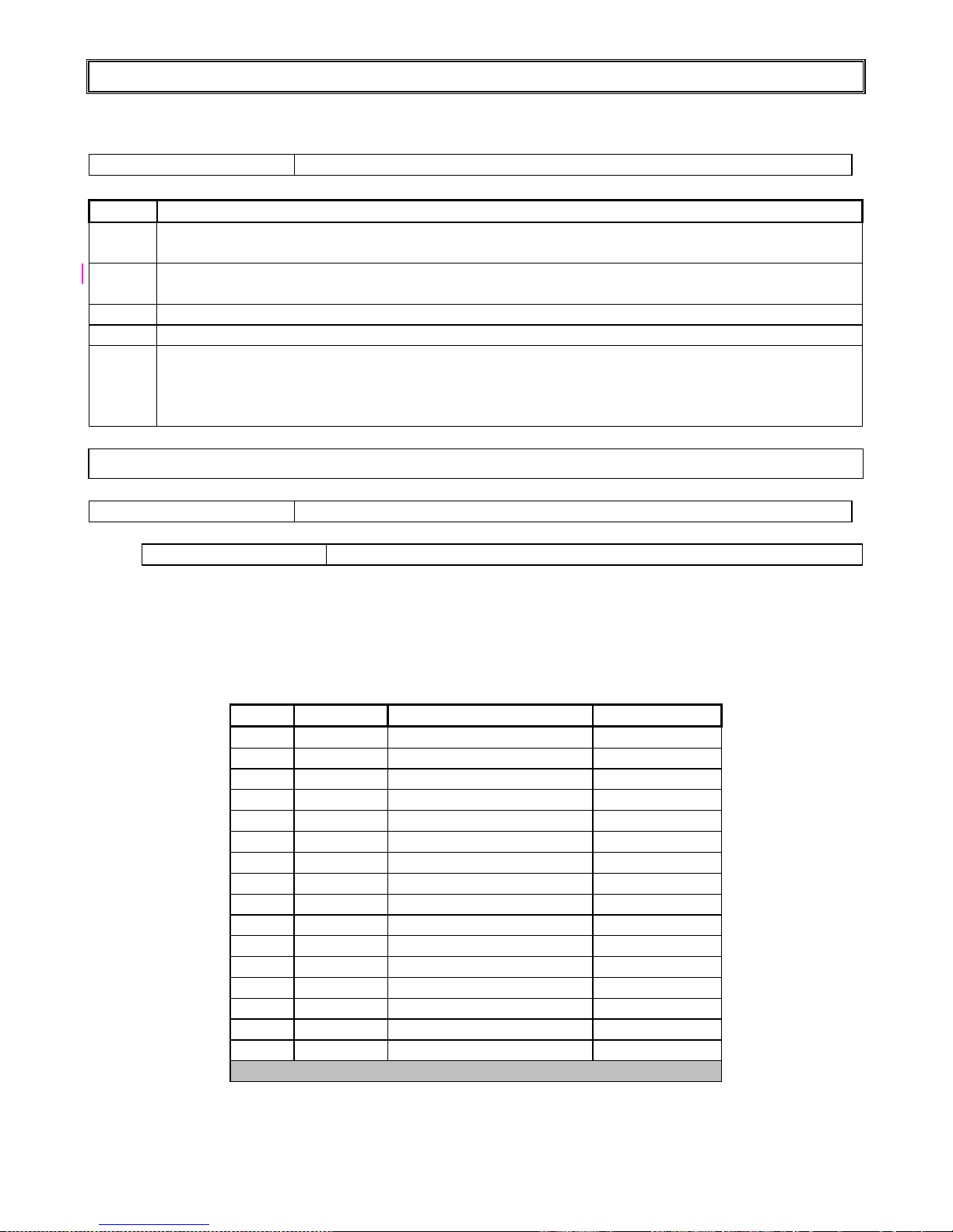
LOCATION 0 Defaulting of the Panel or Master User Code
Value
Action
0
Will reset all locations to the factory default values.
(Master User Code 1234) and all keypad IDs will be defaulted.
1
Will default the master user code to 1234 - or 123456 if 6 digits are being used.
Master user code properties will also be defaulted.
2 Defaults ALL users
3 Defaults ALL keypads
4
Remove Missing Devices
Any missing devices (keypads, for example), will have its address freed up, making its address
available for a new device when it is enrolled. This MUST be performed when replacing a faulty
device – see “Enrolling Keypads and Other Devices”, page 14.
7.6.1 Zone Options
LOCATIONS 1 - 32
Individual Zone Setup
Sub-location 1 Zone Type
The first sub-locations of program LOCATIONS 1 - 32 are used to define the zone characteristics of each
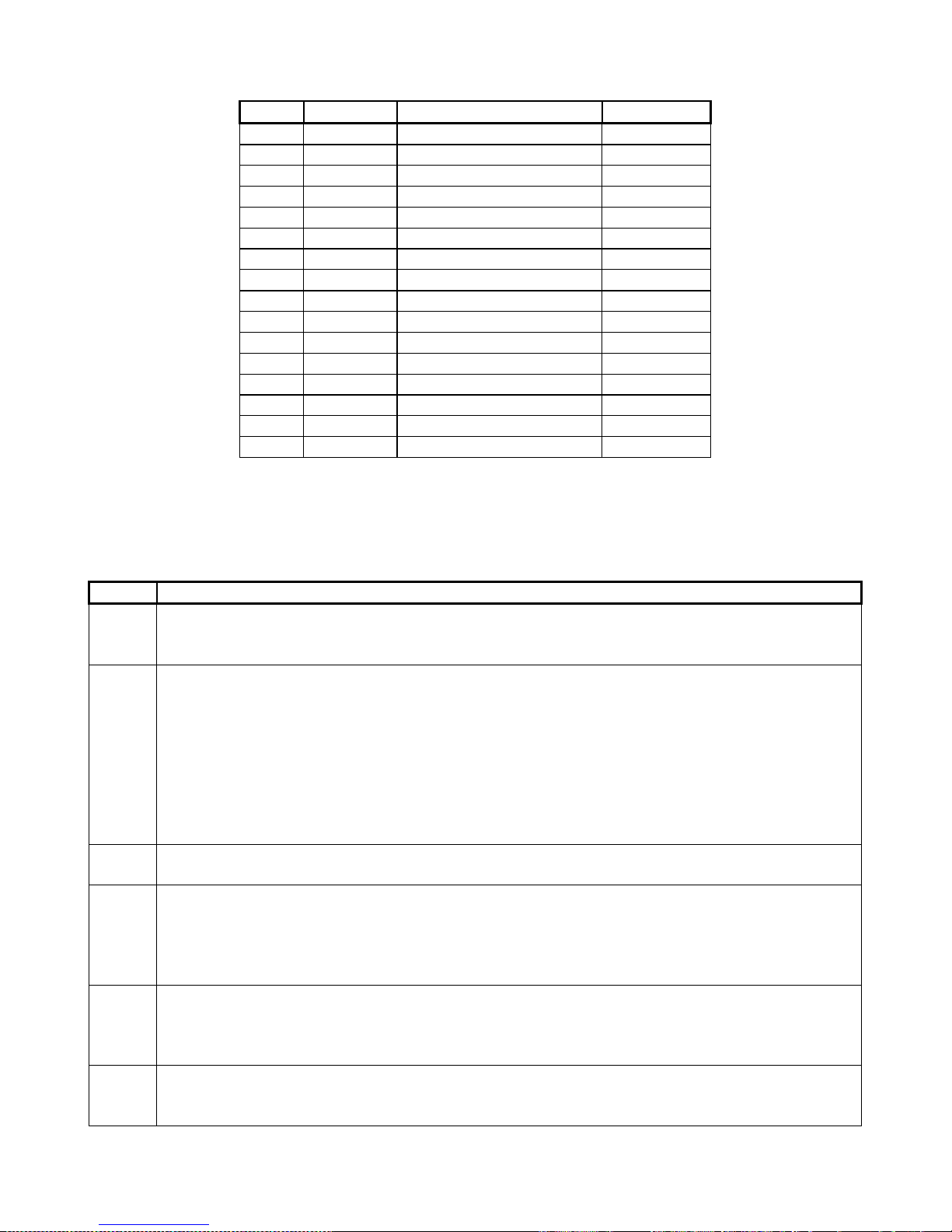
of the thirty two zones. There are 13 zone types. Table 3 provides a location/zone cross-reference
together with the default zone characteristics.
Table 3 : Location / Zone Defaults
Zone
Location
Sub-location 1 Default
Zone Type
1 1 1 Entry / Exit
2 2 2 Follower
3 3 4 Audible Instant
4 4 4 Audible Instant
5 5 4 Audible Instant
6 6 4 Audible Instant
7
7
4
Audible Instant
8
8
4
Audible Instant
9
9
4
Audible Instant
10 10 4 Audible Instant
11 11 4 Audible Instant
12 12 4 Audible Instant
13 13 4 Audible Instant
14 14 4 Audible Instant
15 15 4 Audible Instant
16 16 4 Audible Instant
Table continues on the next page
Page 21
IDS 1632 Installer Manual 700-256-02K Issued September 2009
21
Table 3 : Location / Zone Defaults, Continued…
Zone
Location
Sub-location 1 Default
Zone Type
17 17 0 Disabled
18 18 0 Disabled
19 19 0 Disabled
20 20 0 Disabled
21 21 0 Disabled
22 22 0 Disabled
23
23
0
Disabled
24 24 0 Disabled
25 25 0 Disabled
26 26 0 Disabled
27 27 0 Disabled
28 28 0 Disabled
29 29 0 Disabled
30 30 0 Disabled
31 31 0 Disabled
32 32 0 Disabled
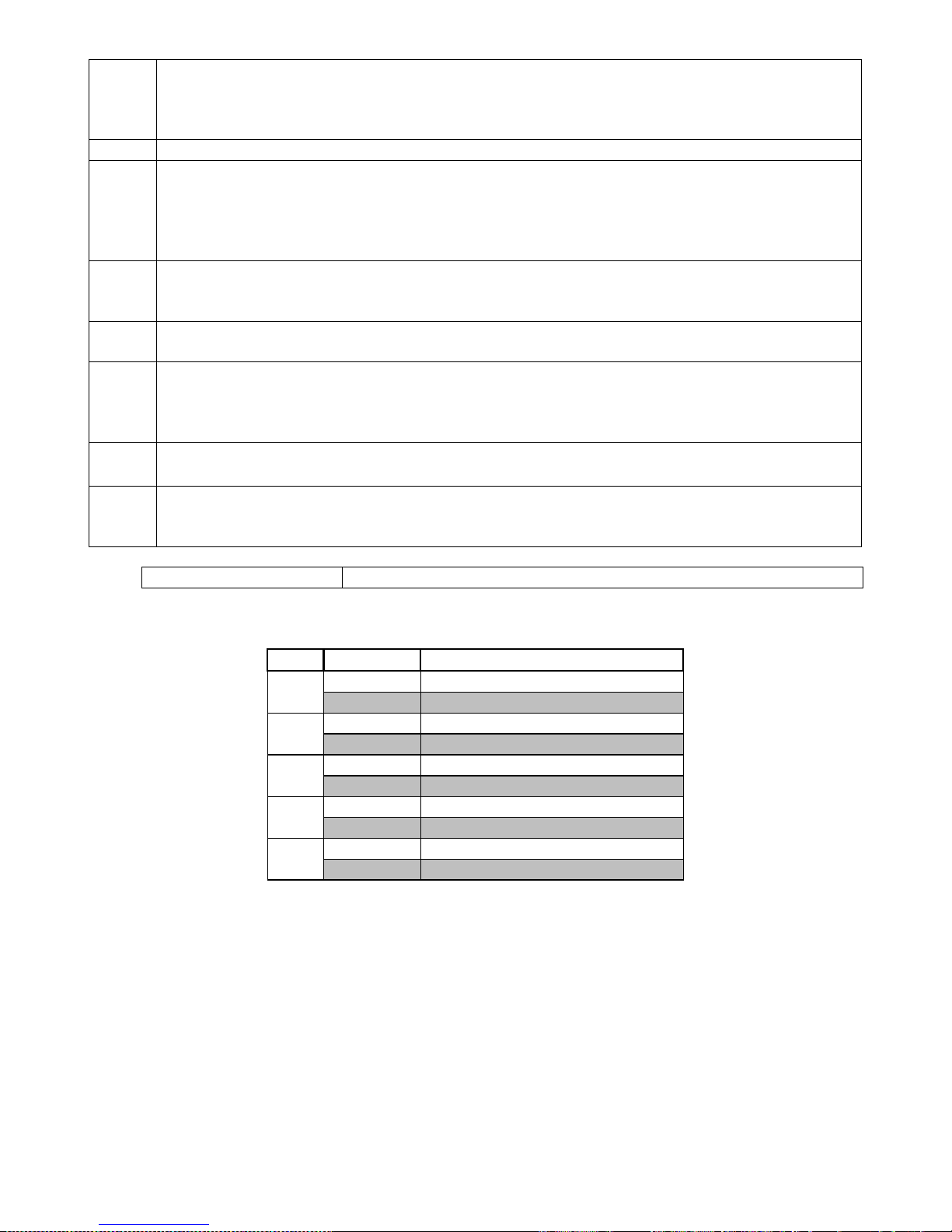
Table 4 provides a complete list of the different zone types together with a description of their
characteristics.
Table 4 : Programmable Zone Types
Value
Zone Type
0
DISABLED
A Zone violation of a disabled zone is ignored by the control panel and will not be indicated on
the keypad.
1
PRIMARY ENTRY / EXIT ZONE
Violations of an Entry/Exit zone are ignored during the exit delay period of the arming
procedure. Violating an Entry/Exit zone when armed will initiate the entry delay. If valid User
Code is not entered before the entry delay period expires, an alarm condition will be registered.
Failure to exit through an Entry/Exit zone after arming will cause the panel to Stay Arm.
This zone may also function as an entry/exit zone that is COMMON to two partitions. In such a
case, should a user violate this zone and then disarm his partition, the OTHER partition will re-
arm after the entry delay.
8
SECONDARY ENTRY / EXIT ZONE
The secondary entry delay will be activated if this zone is violated when the panel is armed.
2
FOLLOWER ZONE
A violation of a Follower zone is ignored during the entry/exit delay period (this allows the user
to enter/exit via the follower zone).
A Follower zone will behave as an instant zone if the panel is armed and an entry/exit zone is
not violated prior to violation of the follower zone.
3
PANIC / PRIORITY ZONE
Regardless of whether the panel is armed or not, a violation of a Priority zone will cause the
control panel to register a panic condition.
This zone type CANNOT be bypassed.
4
INSTANT ZONE
When the panel is armed, the violation of an instant zone will cause the control panel to register
an alarm condition.
Page 22
IDS 1632 Installer Manual 700-256-02K Issued September 2009
22
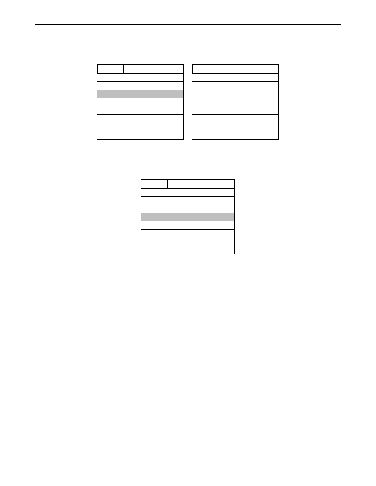
5
ARM / DISARM ZONE
The violation of an Arm/ Disarm zone will cause the panel to toggle between (away) armed and
disarmed. It is typical to connect a momentary key-switch, or non-latching remote control unit to
this zone.
9 RESERVED
10
FIRE ZONE
Violation of a Fire Zone will cause the siren to sound regardless of whether the panel is armed
or not. The siren will sound intermittently (one second on, one second off) For correct operation
a programmable output programmed as a fire detector power output must be used to control
power to the fire detector.
11
TAMPER ZONE
Violation of this zone will be reported to the base station regardless of whether the panel is
armed or disarmed. If the panel is armed, the siren will be activated.
12
24 HOUR ALARM ZONE
This works the same as a panic zone – with the exception that it is able to be bypassed.
13
WARNING ZONE
When the panel is armed, violation of a warning zone will cause the siren to beep. The violation
is logged in the event log but it is not reported to the base station. Warning zones may be
included and will be counted when used as part of the cross-zone matrix.
14
PUSH TO ARM ZONE
Violation of a push to arm zone during the exit delay will immediately arm the panel.
15
OUTDOOR INSTANT ZONE
When the panel is armed violation of an outdoor instant zone will cause the panel to register an
alarm condition.
Sub-location 2 Zone Properties (Defaults Shaded)
Bitmapped location – select all properties for Zone
LED
ON / OFF
Zone Properties
1
ON Tamper by Zone Enabled
OFF Tamper by Zone Disabled
2
ON Cross-Zone Enabled
OFF Cross-Zone Disabled
3
ON Shutdown Zone Enabled
OFF Shutdown Zone Disabled
4
ON
Silent Zone Enabled
OFF
Silent Zone Disabled
5
ON
Second Loop Response Enabled
OFF Second Loop Response Disabled
Further zone related functionality explained
Tamper by Zone
Individual zones may be enabled for tamper by zone. For connection details, see Figure 2. This feature is
not available if zone doubling is enabled. (See Figure 3, page 12 and Location 38, page 26)
Cross-Zoning
This feature is useful for reducing false alarms. Violating zones with the cross-zone property enabled will
not immediately generate an alarm. The Cross-Zone Delay Timer is started. See Location 36.
Depending on the value programmed into location 37 (Cross-Zone Trip Count), the zone (or
any other zone with cross-zone option enabled) must trip the number of times programmed into location
Page 23

IDS 1632 Installer Manual 700-256-02K Issued September 2009
23
37 before an alarm is generated. An alarm will also be generated should any single zone remain violated
for the entire delay period (Location 36). An entry/exit cannot be cross-zoned.
Swinger Shutdown
During a single arm cycle if the number of alarm violations generated by a swinger zone equals the
shutdown count (Location 33) the control panel will automatically bypass the that zone. The swinger
shutdown counter will reset when the system is disarmed and can be programmed to reset automatically
when the 24 hour self test report is generated. See Sub-location 5 of Locations 128 and 135 [Partition
Setup]
Silent Zone
This property allows any zone that would ordinarily activate the siren to be programmed as a silent zone
i.e. the violation of a silent zone while the system is armed will not activate the siren. However,
the
relevant reporting code (if programmed) will still be reported.
Zone Reporting Codes
NOTE:
For the following locations, a two digit hexadecimal code must be programmed. To disable a reporting
code a double zero (00) must be entered. If a zero is to be reported, it must be entered as hexadecimal
value A, i.e. [MODE] [0]. In the event that only 1 of the digits is programmed or an A is incorrectly
programmed as a zero the code will not be reported. If domestic reporting is used, only the first digit of
the reporting code is required / used.
Sub-location 3 Alarm Reporting Code
This is the code transmitted when the zone is violated during an arm cycle or if a panic or 24 Hour Zone
is violated.
Sub-location 4 Alarm Restoral Reporting Code
The zone restoral code is transmitted when the zone has returned to the “unviolated” condition after
triggering an alarm.
Sub-location 5 Bypass Reporting Code
A zone bypass code will be reported when a zone has been bypassed and the panel is armed.
Sub-location 6 Force Arm Reporting Code
This code will be transmitted if a partition is programmed to allow forced arming (arming with a violated
zone) and a zone is violated at the time of arming.
Sub-location 7 Tamper Reporting Code
The tamper code will be reported if tamper-by-zone has been enabled and a zone tamper occurs.
Sub-location 8
Tamper Restore Reporting Code
When a zone tamper condition clears, this code will be reported.
Page 24

IDS 1632 Installer Manual 700-256-02K Issued September 2009
24
Sub-location 9 Swinger Shutdown Reporting Code
The swinger shutdown zone code will be reported if the system is armed and a zone is automatically
bypassed as a result of multiple violations of that zone.
Sub-location 10 Swinger Shutdown Restore Reporting Code
If enabled, this code will be reported when a swinger shutdown zone is automatically restored i.e. unbypassed.
Sub-location 11 Zone Programmable Output Location
A programmable output will be pulsed or latched, high or low if a zone causes an alarm condition. If
pulsed, the output will be pulsed for the time programmed in Sub-location 1 of Locations 388 - 399.
Two digits must be programmed for each zone. The first digit references the programmable
output number e.g. output 1 to 5 (7 with an expander). The second digit sets the output action. Refer
“System Programmable Outputs” (Page 32) for a detailed description on Programming Programmable
Outputs.
Sub-location 12 Zone Name Editing (Only with LCD keypads)
Zones may be given appropriate names, like “Front Door” for zone 1, etc. When the zone is triggered, the
display will indicate “Front Door”, instead of “Zone 1”. (Full instructions are included in the LCD keypad
manual.)
7.6.2 System Options
LOCATION 33 Zone Shutdown Count (Default = 5)
Determines the number of times a zone may be violated during an arm cycle before it is automatically
bypassed. Select zones individually for this option in locations 1 – 32s (Sub-location 2). Valid range of
data for this location is 1 to 15.
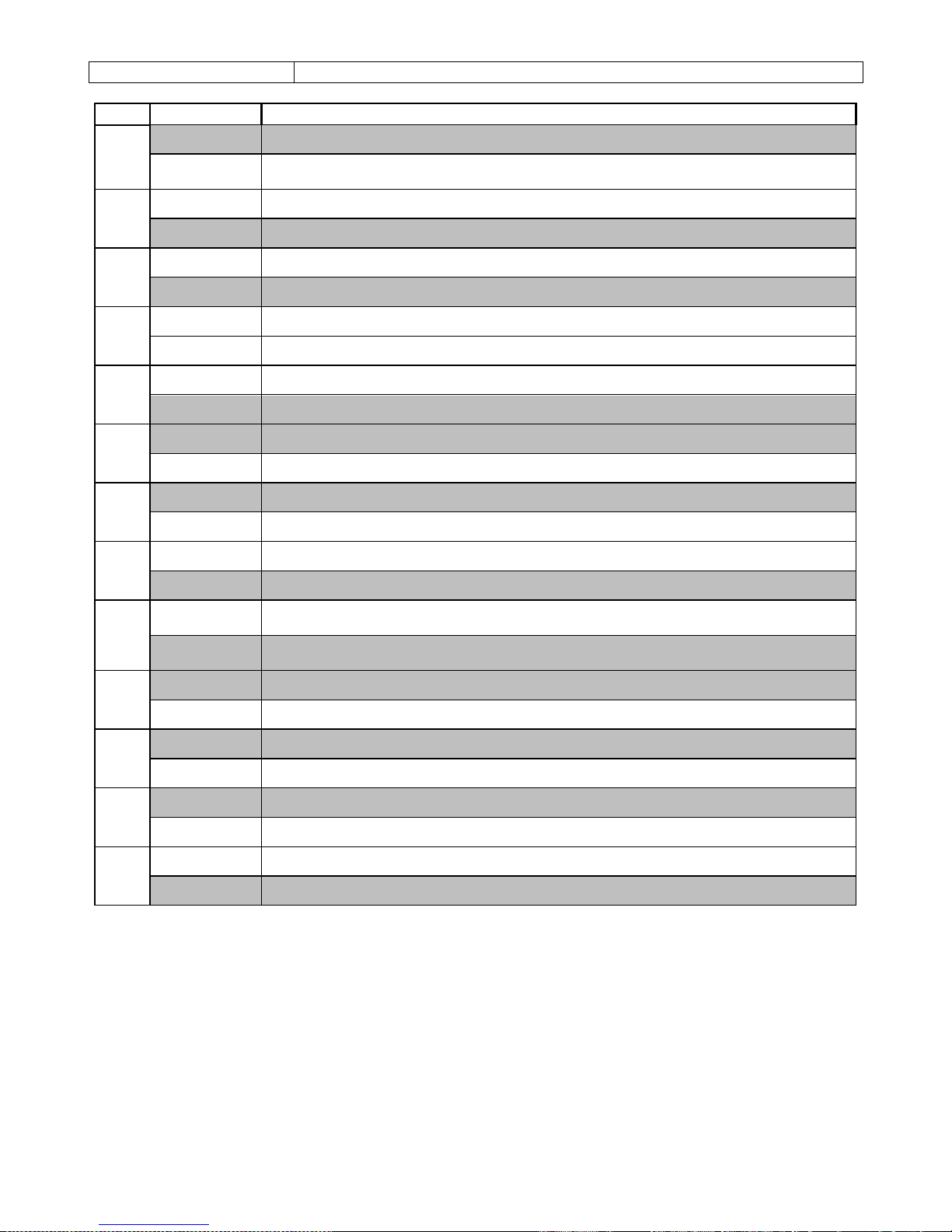
LOCATION 34 Programmable Zone Loop Response Time
Value
Response Time
Value
Response Time
0 6 ms 8 96 ms
1 12 ms 9 108 ms (default)
2 24 ms 10 120 ms
3 36 ms 11 132 ms
4 48 ms 12 144 ms
5 60 ms 13 156 ms
6 72 ms 14 168 ms
7 48 ms 15 180 ms
The zone loop response is the period of time for which the programmed zone must remain violated
before a violation is registered. Unless the Second Loop Response Time is selected, this location will
determine the response time.
Page 25
IDS 1632 Installer Manual 700-256-02K Issued September 2009
25
LOCATION 35 Second Loop Response Time
The first and second loop response times are two preset delay periods that are initiated by the options
selected in locations 1 to 32, sub-location 2, bit 5.
Value
Response Time
Value
Response Time
0 6 ms 8 96 ms
1 12 ms 9 108 ms
2 24 ms (default) 10 120 ms
3
36 ms
11
132 ms
4
48 ms
12
144 ms
5 60 ms 13 156 ms
6 72 ms 14 168 ms
7 48 ms 15 180 ms
LOCATION 36
Cross-Zone Delay Timer
This location defines the cross-zone delay timer period.
Value
Response Time
0 3 seconds
1 10 seconds
2 15 seconds
3 20 seconds (default)
4
25 seconds
5
30 seconds
6
45 seconds
7 1 Minute
LOCATION 37
Cross-Zone Count (Default = 2)
If the panel is armed and the total number of violations of zones programmed as cross-zones reaches
this count within the time period programmed into location 36, an alarm condition will be registered.
Program a value from [0] to [1] [5]. A [0] will disable this location. Program zones as cross-zones in sublocation 2 of locations 1 to 16. Any single zone enabled for cross zoning, which is violated continuously
for the time specified in Location 36 will also register an alarm condition.
Page 26
IDS 1632 Installer Manual 700-256-02K Issued September 2009
26
LOCATION 38 Global Options
LED
ON / OFF
Action
1
ON
A user assigned to any partition may cancel the siren
OFF
Only a user assigned to the partition that triggered the siren may cancel the
siren
2
ON
Enables keypad trouble beep
OFF
Disables keypad trouble beep
3
ON
Enables telephone line monitoring
OFF
Disables telephone line monitoring
4
ON
RESERVED
OFF
RESERVED
5
ON
Enables keypad beep on communication
OFF
Disables keypad beep on communication
6
ON
Enables keypad Fire, Medical and Panic keys
OFF
Disables keypad Fire, Medical and Panic keys
7
ON
Enables the display of bypassed and stay zones when armed in the stay mode
OFF
Disables the display of bypassed and stay zones when armed in the stay mode
8
ON
Enables the siren delay
OFF
Disables the siren delay
9
ON
Enables zone doubling (All expanded / keypads zones
ignored)
OFF
Disables zone doubling (expansion / keypad zones can be used to expand the
system to sixteen zones.)
10
ON
Enable Box Tamper
OFF
Disable Box Tamper
11
ON
Enable Siren Tamper
OFF
Disable Siren Tamper
12
ON
Enable 485 Device Tamper
OFF
Disable 485 Device Tamper
13
ON
Dedicated Panic Zone – Silent
OFF
Dedicated Panic Zone – Audible
Page 27
IDS 1632 Installer Manual 700-256-02K Issued September 2009
27
LOCATION 39 AC Fail / Restore Time
Value
Delay
0 3 seconds
1 10 seconds
2 15 seconds
3 20 seconds
4 25 seconds
5
30 seconds
6
45 seconds
7 1 minute
8 2 minutes
9 3 minutes
10 4 minutes
11 5 minutes
12 10 minutes
13 15 minutes
14 18 minutes
15 21 minutes
16
1 hour
17
2 hours
18 3 hours
19 4 hours
20 10 hours
In the event of a power failure (although instantly displaying the trouble indication) the panel will wait for
this period of time before REPORTING the mains failure. The same time period applies before the restoral
event is reported and logged. This delay eliminates unnecessary reporting if the AC power is removed for
a short time period.
It is important to note that an AC restoral will only be reported if an AC failure was reported, i.e.
the delay period was exceeded. Provided the back up battery is in good condition, short AC power
failures will not affect the functioning of the alarm system. Select the appropriate value from the table
above.
Page 28
IDS 1632 Installer Manual 700-256-02K Issued September 2009
28
LOCATION 40 Trouble Display
LED
ON/ OFF
Action
1
ON
Enable AC fail trouble display
OFF
Disable AC fail trouble display
2
ON
Enable Comms fail trouble display
OFF
Disable Comms fail trouble display
3
ON
Enable phone line trouble display
OFF
Disable phone line trouble display
4
ON
Enable siren tamper trouble display
OFF
Disable siren tamper trouble display
5
ON
Enable low battery detection trouble display
OFF
Disable low battery detection trouble display
6
ON
Enable clock loss trouble display
OFF
Disable clock loss trouble display
7
ON
Enable engineer's reset trouble display
OFF
Disable engineers reset trouble display
8
ON
Enable box tamper trouble display
OFF
Disable box tamper trouble display
9
ON
Reserved
OFF
Reserved
10
ON
Enable 485 device trouble display
OFF
Disable 485 device trouble display
11
ON
Enable bus trouble display
OFF
Disable bus trouble display
12
ON
Enable Aux. 12V trouble display
OFF
Disable Aux. 12V trouble display
13
ON
Reserved
OFF
Reserved
14*
ON
Enable SIM Code Trouble Display
OFF
Disable SIM Code Trouble Display
15*
ON
Enable GSM Modem Trouble Display
OFF
Disable GSM Modem Trouble Display
16*
ON
Enable Low Airtime Trouble Display
OFF
Disable Low Airtime Trouble Display
Default values are shaded
* Applicable only with IDS GSM Communicator installed
Location 40 determines which trouble conditions are displayed on the trouble menu. A trouble condition
is indicated by a flashing POWER LED. Not withstanding the disabling of a trouble condition from the
viewing menu the relevant code will be reported if programmed to do so.
Trouble conditions will be reported if programmed to do so in locations 118, 119 & 120,
regardless of whether or not they are enabled for display.
The trouble condition can be viewed by holding down the [7] key for three seconds. See
“Viewing Trouble Conditions” in the user manual.
Page 29
IDS 1632 Installer Manual 700-256-02K Issued September 2009
29
LOCATION 41 Siren Time Out Period
Value
Delay
0 3 seconds
1 10 seconds
2 15 seconds
3 20 seconds
4 25 seconds
5 30 seconds
6 45 seconds
7 1 minute
8
2 minutes
9 3 minutes
10 4 minutes
11 5 minutes
12 10 minutes
13 15 minutes
14 18 minutes
15 21 minutes
The siren time out period is the period of time for which the siren will sound after an audible alarm
condition is registered. Select the appropriate time period from the table above.
LOCATION 42 Siren Delay
When an audible alarm is registered, a delay can be implemented before the siren is triggered. The alarm
will however be reported as soon as it occurs. Enable option 8, Location 38.
Value
Delay
0 3 seconds
1
10 seconds
2
15 seconds
3
20 seconds
4 25 seconds
5 30 seconds
6 45 seconds
7 1 minute
8 2 minutes
9 3 minutes
10 4 minutes
11 5 minutes
12
10 minutes
13
15 minutes
14
18 minutes
15 21 minutes
LOCATION 43
Keypad Lockout Count (Default = 4)
If a partition has keypad lockout enabled this value determines the number of consecutive incorrect
codes that will activate a keypad lockout. The keypad will remain locked for the time
programmed in
Location 44. Activating a Keypad Panic (or Medical or Fire Emergency) will unlock the keypad.
Page 30
IDS 1632 Installer Manual 700-256-02K Issued September 2009
30
LOCATION 44 Keypad Lockout Time (Default = 30 seconds)
The value programmed into this location determines the keypad lockout period. The valid range is 0 - 255
seconds.
NOTE:
Keypad lockout is enabled by partition.
See Partition Options Page 48, Sub-location 5.
LOCATION 45 Keypad Sleep Delay
The values stored in this location work in the same way as siren delay (table on page 29). The default
value is 11, which equates to 5 minutes.
NOTE:
This function is set individually per keypad (locations 400 to 415). After this time period, if there is no
keypad activity (on this keypad) the backlighting and all other status and alarm indicators will turn off. The
power LED and if appropriate, the arm LED will remain on.
LOCATION 46 User and Installer Code Number of Digits
This location determines whether 4 or 6 digit user / installer codes are applicable. Only a value of four or
six may be programmed into this location. By default, all codes are four digits in length.
The value programmed into this location has no effect on the download code, which are always 4 digits
in length.
Code
Old four-digit code
New six-digit code
All Previously
Programmed codes
XXXX XXXX00
Installer Code
9999
999999
Master User Code 1
1234
123456
8. System Reporting Codes (4 x 2 and Domestic)
For all these locations, a two digit hexadecimal code must be programmed. To disable a reporting code
a double zero (00) must be entered into the corresponding location. Note that if one of the above
mentioned reporting digits is inadvertently omitted or programmed as a zero, the code will not be
reported. The exception to this rule is when using domestic reporting where only the first digit is used.
LOCATION 47 AC Failure Reporting Code
The control panel will transmit this code in the event of an AC failure but only after the AC failure delay
time has elapsed (See Location 39).
LOCATION 48 AC Restoral Code
The control panel will transmit this code once the AC restore delay time has elapsed. (See location 39). It
will however only be reported if an AC failure was registered as per location 47.
Page 31
IDS 1632 Installer Manual 700-256-02K Issued September 2009
31
LOCATION 49 Low Battery Reporting Code
A low battery condition is reported when the battery voltage drops below 11.8V for a period longer than 5
minutes or immediately if it drops below 10V.
LOCATION 50 Battery Restore Reporting Code
This code is reported once the battery voltage rises above 12 volts for a period of five minutes.
LOCATION 51 Auto Test Reporting Code
This code is reported at regular intervals. See location 112, page 37.
LOCATION 52
Download Access Reporting Code
This code is reported once successful access to the panel has been obtained.
LOCATION 53 Siren Trouble Reporting Code
This code is reported when the siren fuse blows or when the siren or siren wiring is tampered with.
LOCATION 56 Device Tamper Reporting Code
This code is reported when there is a tamper condition on any external device attached to the keypad
bus.
LOCATION 57 Keypad Bus Failure Reporting Code
This code is reported when there is a fault on the keypad bus
LOCATION 58 Box Tamper Reporting Code
This code is reported when the box tamper contacts are open for a period exceeding 200 ms.
LOCATION 59 Dedicated Panic Reporting Code
This code is reported when the dedicated panic zone is violated.
LOCATION 60 Phone Line Restoral Reporting Code
If phone line monitoring is enabled (Location 38), this code is reported once phone line integrity has been
restored to indicate that the phone line has been tampered with.
LOCATION 61 RF Jamming Reporting Code
This reporting code will be reported if a jamming signal is detected by the RF receiver module for a
period exceeding 30 seconds.
LOCATION 62 RF Jamming Restore Reporting Code
This reporting code will be reported once the jamming signal has ceased for a period exceeding 30
seconds.
Page 32
IDS 1632 Installer Manual 700-256-02K Issued September 2009
32
9. System Programmable Outputs
Programming the Outputs:
Programmable outputs are able to toggle between different states when specific system events occur.
Either single or multiple events may be programmed to a particular output.
For most events the action of an output, when triggered, is programmable. To program these
events a two digit code must be entered. The output action for certain events is fixed – and function
driven, the strobe function is one example. For these events, only a single digit code need be
programmed.
There are eight programmable outputs on the IDS 1632 Alarm Panels and a further two
programmable outputs on each of the optional Wired Zone Expander modules. When selecting outputs,
programmable outputs on the Alarm Panels are addressed from “1” to “12“.
Outputs on the Wired Zone Expanders are addressed as “9”, “10”, “11” and “12” – (refer to table 5).
Table 5 : Programmable Output Numbering
Value
Programmed as
Output Addressed
0 [0] No Output Addressed
1
[1]
Panel - Programmable Output 1
2
[2]
Panel - Programmable Output 2
3 [3] Panel - Programmable Output 3
4 [4] Panel - Programmable Output 4
5 [5] Panel - Programmable Output 5
6 [6] Panel - Programmable Output 6
7 [7] Panel - Programmable Output 7
8 [8] Panel - Programmable Output 8
9 [9] Zone Expander 2 - Programmable Output 2
10 [MODE] [0] Zone Expander 2 - Programmable Output 1
11 [MODE] [1] Zone Expander 1 - Programmable Output 2
12
[MODE] [2]
Zone Expander 1 - Programmable Output 1
There are 4 permitted output actions that may be selected.
Table 6 : Output Actions
Value
Output Action
0 Set Output High (Set)
1 Set Output Low (Reset)
2 Pulse Output High
3 Pulse Output Low
When programming these outputs a two-digit code must be entered. The first digit references the
programmable output number (Table 5) and the second digit references the output action (Table 6).
Example:
Entering a value of [1][0] into location 70 will cause Panel Programmable Output 1 to be set (latched)
high in the event of an AC Mains Failure. Entering a value of [1][1] into location 71 will cause the Panel
Programmable Output 1 to be set (latched) low in the event of an AC Mains Restoral.
Page 33
IDS 1632 Installer Manual 700-256-02K Issued September 2009
33
When programming a programmable output whose action is fixed only a single digit need be entered.
This digit references the programmable output number (Table 5).
Example:
Programming a value of [7] into Sub-location 42 of Location 129 will cause the Zone Expander
Programmable Output 1 to follow the Siren Output for Partition 2.
NOTE:
When connecting any device with a high current requirement to a programmable output a suitable relay
must be used. DO NOT connect such devices directly to the programmable outputs as this may damage
the output circuitry.
LOCATIONS 70 - 87 Event Driven Programmable Outputs
Table 7 : Event Driven Programmable Outputs
Loc.
Event
Output
Default Action
70
AC Fail Programmable Output
disabled
71
AC Restore Programmable Output
disabled
72
Low Battery Programmable Output
disabled
73 Battery Restore Programmable Output disabled
74 Auto Test Programmable Output disabled
75 Download Programmable Output disabled
76 Siren Trouble Programmable Output disabled
77 Aux 12V Trouble Programmable Output disabled
78 Keypad Fuse Programmable Output disabled
79 485 Device Tamper Programmable Output disabled
80 485 Bus Failure Programmable Output disabled
81
Box Tamper Programmable Output
disabled
82
Dedicated Panic Programmable Output
1
Pulse High [2]
83
Communication Fail Programmable Output
disabled
84 Phone Line Tamper Programmable Output disabled
85 Phone Line Restore Programmable Output disabled
86 RF Jamming Programmable Output disabled
87 RF Jamming Restore Programmable Output disabled
LOCATIONS 95 – 96 Function Driven Programmable Outputs
Table 8 : Function Driven Programmable Outputs
Summary of System function Driven Programmable outputs
Loc.
Function
Output
95 Fire Sensor Power Programmable Output Disabled
96 Dual Reporting Programmable Output Disabled
Page 34
IDS 1632 Installer Manual 700-256-02K Issued September 2009
34
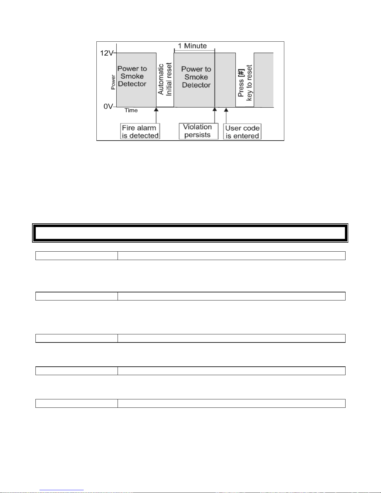
Figure 6 : Fire Detect Output Sequence
NOTE:
Since multiple conditions may be programmed to a single output it is essential to ensure that no
unwanted conditions are assigned to an output.
Dual Reporting Output
If dual reporting is enabled this output will be set when the panel dials the second phone number, and
cleared when it hangs up at the end of transmission. This output follows the hook relay. It may be used to
trigger switching from the telephone line to a radio transmitter.
10. System Clock Options
LOCATION 98 System Time
Enter the system time. The format is “hhmm” and is based on a 24 hour clock. (All 4 digits must be
entered.)
LOCATION 99 System Day of Month
Enter a two digit value of the current day of the month.
Valid range 01 to 31.
LOCATION 100 System Month
Enter the month as a value from 01 to 12.
LOCATION 101 System Year
Enter the current year as a four digit value e.g. 2007.
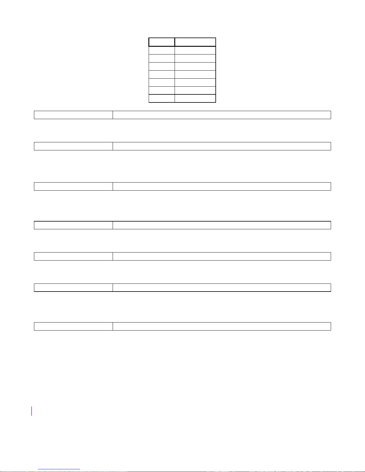
LOCATION 102 System Day of Week
Enter the current day of the week. Refer to table below.
Page 35
IDS 1632 Installer Manual 700-256-02K Issued September 2009
35
Table 9 : Value for Day of the Week
Value
Day
1 Monday
2 Tuesday
3 Wednesday
4 Thursday
5 Friday
6 Saturday
7 Sunday
LOCATION 103 Month to Start Daylight Saving
Enter the month when Daylight Saving will commence.
LOCATION 104 Day of Week to Start Daylight Saving
Enter which day of the week Daylight saving is to commence.
Refer to Location 102 Table 9.
LOCATION 105
Week of Month to Start Daylight Saving
Enter which week of the month Daylight Saving is to commence. If the last week of the month is wanted,
program a five (5).
LOCATION 106
Month to Return to Standard Time
Enter the month when Daylight Saving reverts back to standard time.
LOCATION 107 Day of Week to Return to Standard Time
Enter which day of the week (Table 9) that Daylight Saving returns to standard time.
LOCATION 108 Week of Month to Return to Standard Time
Enter which week of the month Daylight Saving will return to standard time. If it is to be the last week of
the month, program a five (5).
LOCATION 109 Daylight Saving Time Offset
This location is used for setting the Daylight Saving offset. Enter the number of minutes the clock will
offset - Valid range 0 to 250.
Page 36
IDS 1632 Installer Manual 700-256-02K Issued September 2009
36
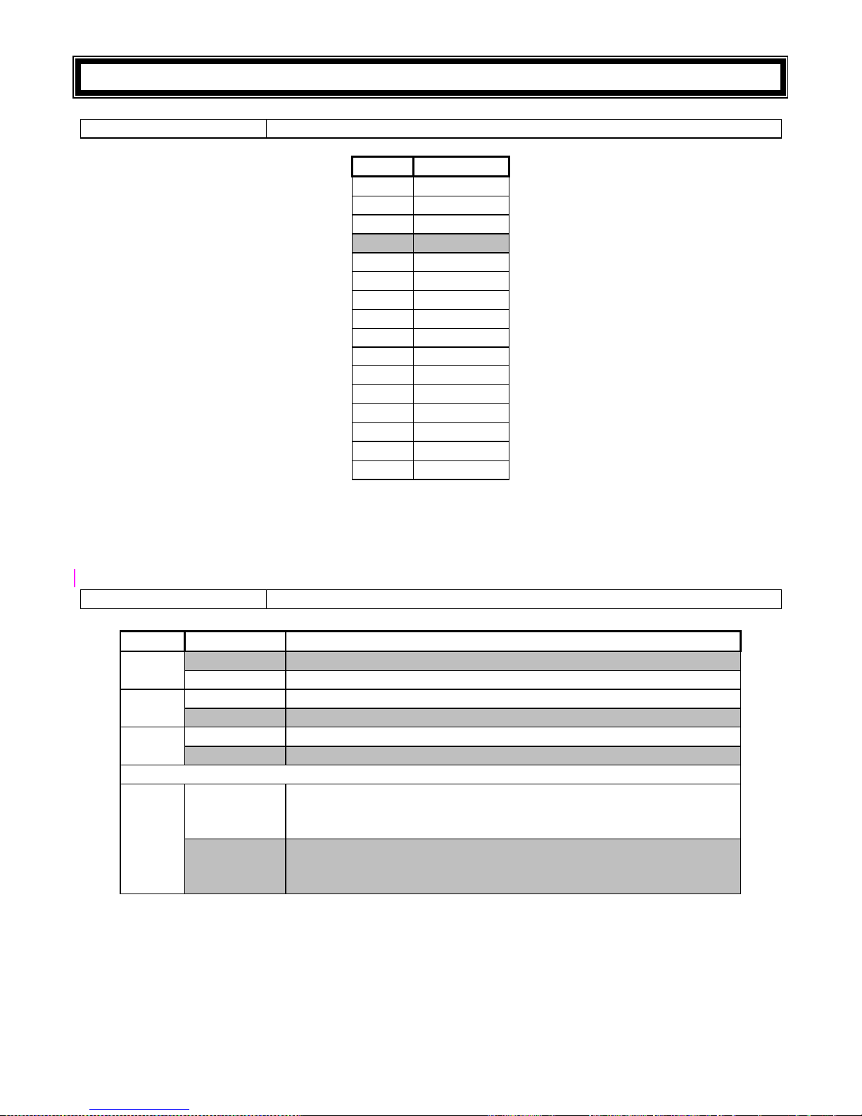
11. Communicator Options
LOCATION 110 Communication Delay
Value
Delay
0 3 seconds
1 10 seconds
2 15 seconds
3 20 seconds
4 25 seconds
5 30 seconds
6 45 seconds
7 1 minute
8 2 minutes
9
3 minutes
10
4 minutes
11 5 minutes
12 10 minutes
13 15 minutes
14 18 minutes
15 21 minutes
If delayed communications is enabled for either partition - (See locations 128 to 135 for Partition Setup)
the panel will wait for this period before reporting zone violations and restorals. If the alarm is cancelled
within this time zone, violations and restorals will not be reported. Violations will however be logged in the
event log. Panic events will be reported instantly – regardless of any selected delay period.
LOCATION 111 Reporting Options
LED
On / Off
Action
1
ON Tone Dialling Enabled
OFF Pulse Dialling Enabled
2
ON Join the telephone numbers together
OFF
Keep two separate telephone numbers
3
ON
Enable Dual Reporting
OFF Disable Dual Reporting
Single reporting options (LED 3 off)
4
ON
Reports to secondary number only after failing on attempting the
primary number.
(Panic event initiates dual reporting)
OFF
Alternates reporting attempts between both numbers until
successful with one of them.
(Single reporting, regardless of panic)
NOTE:
The panel may be programmed to report to a single central station (single reporting) or to report
to 2 central stations (dual reporting).
When programmed for single reporting, the panel default will alternate attempts between the two
“equally ranked” stored numbers. With LED 4 on, the secondary number will only be called if the
Page 37
IDS 1632 Installer Manual 700-256-02K Issued September 2009
37
attempt to report to the primary number fails. In either case, the number of attempts (per phone
number) will be equal to the number stored in location 115, with a default value of 6.
The primary and secondary telephone numbers may be joined to provide for a single telephone
number of 48 digits in length.
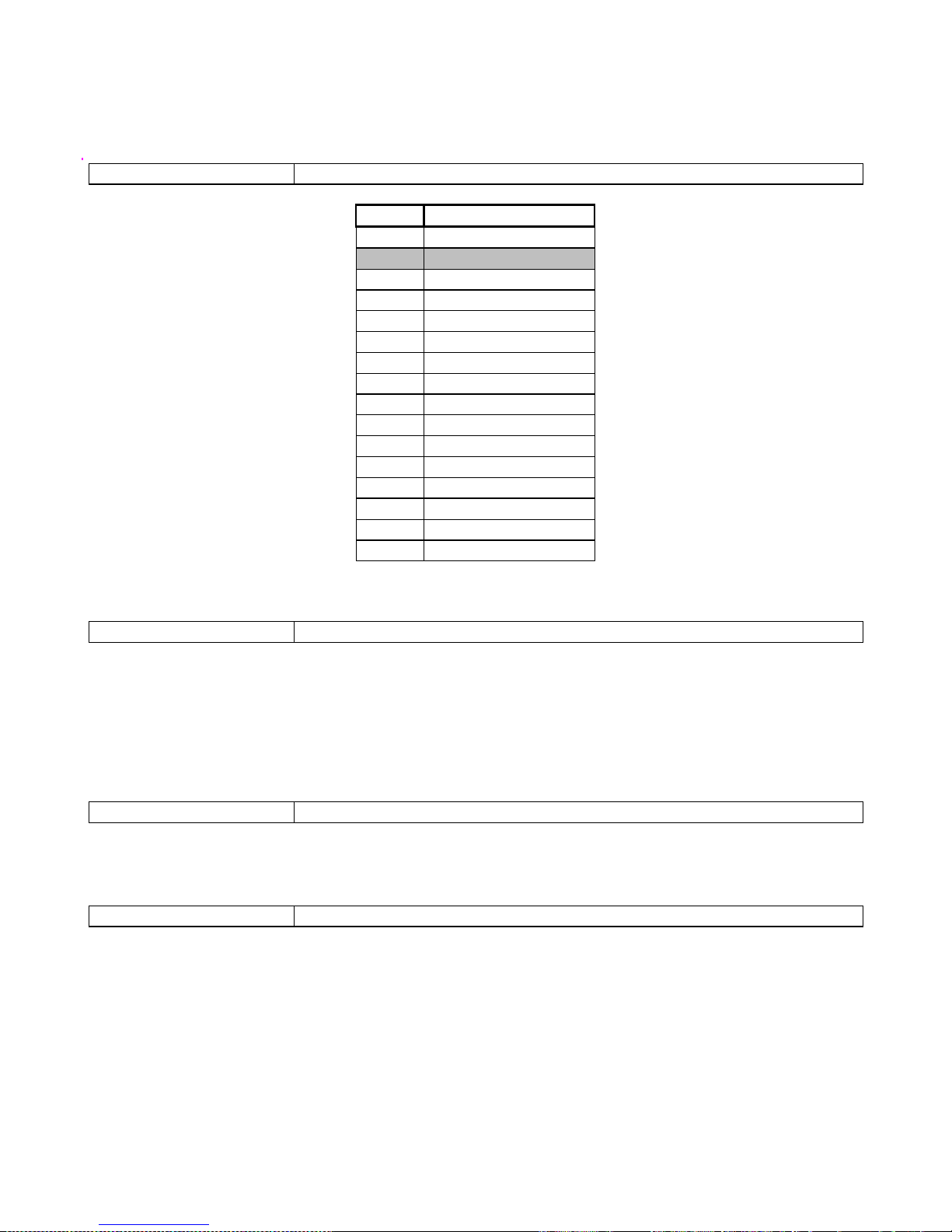
LOCATION 112 Auto Test Interval
Value
Time Period
0 Report every hour
1 Report daily (default)
2 Every two days
3 Every three days
4
Every four days
5
Every five days
6 Every six days
7 Every seven days
8 Every eight days
9 Every nine days
10 Every ten days
11 Every eleven days
12 Every twelve days
13 Every thirteen days
14 Every fourteen days
15
Every fifteen days
The value programmed into this location will determine the duration of time between Auto Tests.
LOCATION 113 Auto Test Time
Enter the time when the auto test will be reported. The format is “hhmm” based on a 24 hour clock. (All
four digits must be entered.)
Example:
If a value of [7] was programmed into location 112 and [1400] was programmed into this location, the
auto test would be sent weekly at 2:00pm.
LOCATION 114 Number of Account Code Digits (Default = 4)
Most reporting formats use a 4 digit account code. Program a 6 into this location to enable six digit
account code reporting.
LOCATION 115 Number of Dial Attempts (Default = 6)
This location determines the maximum number of dial attempts that the panel will make in order to
contact the base station.
NOTE:
Entering [0] into this location will disable the dialler.
Page 38
IDS 1632 Installer Manual 700-256-02K Issued September 2009
38
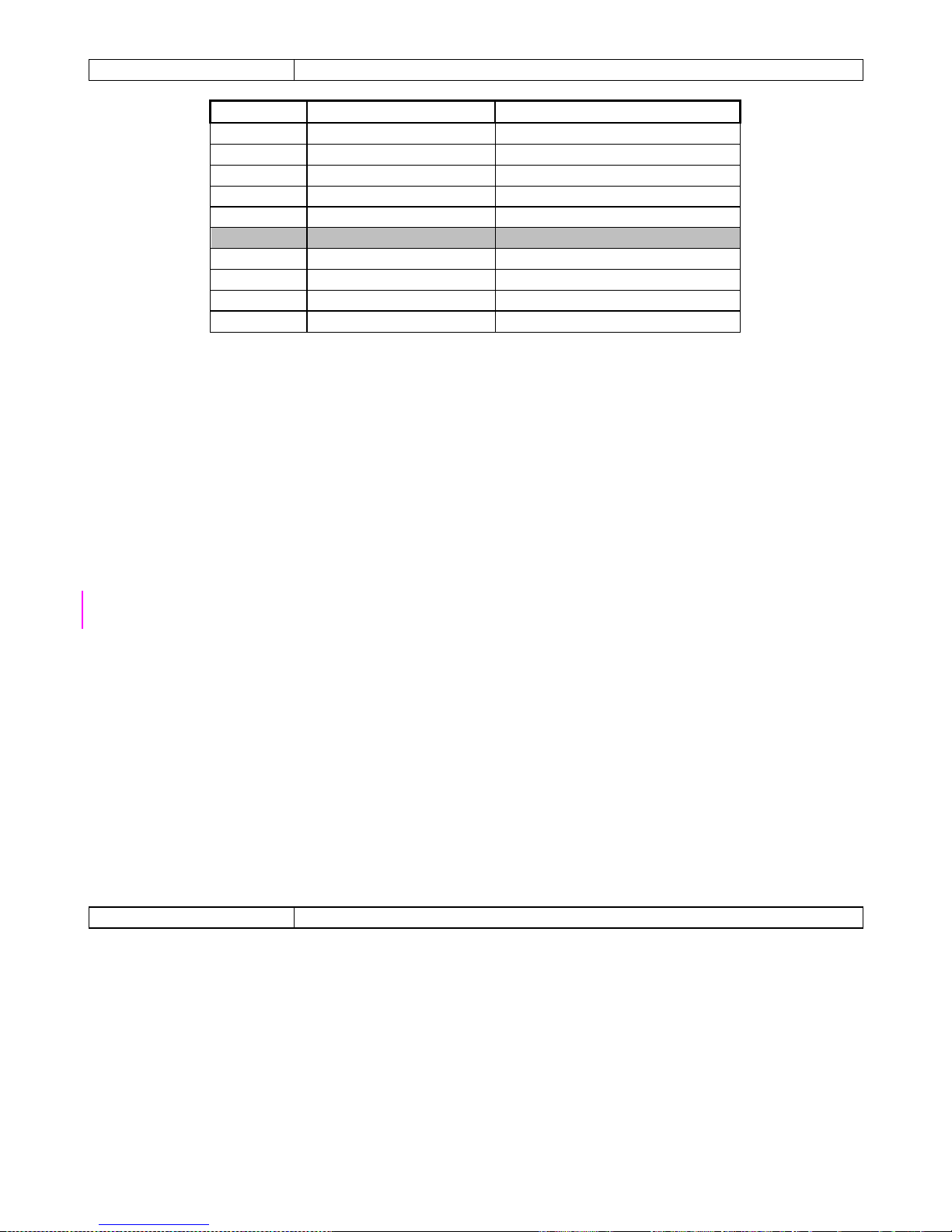
LOCATION 116 Primary Communicator Format
Value
Format Name
Description
0 Ademco Express Dual Tone HS, DTMF
1 FBI 4 x 2 ( With Parity) 1.8kHz TX, 2.3kHz HS, 40PPS
2 FBI 4 x 2 (No Parity) 1.8kHz TX, 2.3kHz HS, 20PPS
3 Silent Knight 4 x 2 Fast 1.9kHz TX, 1.4kHz, 20PPS
4 Silent Knight 4 x 2 Slow 1.9kHz TX, 1.4kHz, 20PPS
5 (Default) Contact ID Dual Tone HS, DTMF
6 Domestic Reporting 1.8kHz TX, Blind, 20PPS
7 SIA Reporting Bell 103 FSK, HS
8
SMS/GSM Reporting
Sends SMS to prescribed Nos.
9 Voice Reporting** Reports to prescribed numbers
TX = Transmit
HS = Handshake
PPS = Pulses per Second
The value entered into location 116 selects the primary communicator format. Select from the table above
the value appropriate to the required format. During communication, the green LED on the PCB will come
one indicating that the panel has taken the telephone off-hook. If programmed accordingly (see location
38), the keypad will beep after receiving a handshake from the base station. This indicates a successful
transmission of data.
Notes on Voice Reporting
Voice reporting works automatically with DTMF dialling once a Voice Module is installed on the Panel.
The voice tells the user what has happened on the panel.
For events that cause a voice report, the Panel will call the relevant number. Six seconds after it has
dialled the last digit, it will begin speaking out its report, speaking each event three times. After all events
are spoken out three times, it hangs up. This identical call is made the number of times stored in Location
115.
The user may terminate the report for the current event by entering their user code (if enabled
in loc 128/129 sub loc 5 bit 5) and then hanging up by pressing #. The call will end and the Panel will not
call again until another reportable event occurs.
Stop report and control the Alarm Panel
If the user enters a valid code during the voice report, the voice report is halted and a DTMF-driven menu
system, with voice prompting, is available by which the user may control the Alarm Panel.
The user may access this control menu by dialling the number of the phone line that the Alarm
Panel wired to (if enabled).
LOCATION 117 Secondary Communicator Format
If dual reporting is enabled then this format will be used to report to phone number 2. (See the same
Table for location 116.)
NOTES ON DUAL REPORTING
When dual reporting is enabled, it is possible to select two different formats. In this instance all data will
be transmitted to each phone number (i.e. reported twice) using a different format per phone number.
Page 39

IDS 1632 Installer Manual 700-256-02K Issued September 2009
39
NOTES ON CONTACT ID / SIA
If the panel has been programmed to use the Contact ID or SIA format, it will not be necessary to
program individual reporting codes. Provision is made to enable/disable the reporting of certain groups
of codes. See location 118 to120. Table 10 contains a list of standard (default) Contact ID reporting
codes. Any event that relates to a specific zone, or to a specific user, will have the relevant zone/user
number appended to the end of the Contact ID reporting code.
Table 10 : Standard Contact ID Reporting Codes
Description
Codes
Description
Codes
Keypad Medical 1100 Cancel 1406
Fire 1110 Open by Download 1407
Keypad Fire 1110 Open with Key-switch 1409
Panic 1120 Low Battery 1302
Panic Zone 1120 Sounder / Relay Trouble 1320
Keypad Panic 1120 Expansion Module Fail 1333
Duress 1121 Zone/ Sensor Bypass 1570
Burglary violation 1130 Zone / Sensor Bypass Restoral 3570
Perimeter Violation
1131
Burg. Bypass
1573
Interior Violation 1132 Test Report 1602
24 Hour (Safe) violation 1133 Panic Restore 3120
Entry/ Exit violation 1134 Zone Restoral 3130
Day/ night violation 1135 Keypad Tamper restore 3137
Outdoor violation 1136 Zone Restoral 3130
Tamper violation 1137 Sensor Tamper Restore 3144
Keypad Tamper 1137 Expansion Module Tamper Restore 3145
Keypad lockout 1137 RF Low Battery Restore 3384
Near Alarm Violation 1138 Close by User 3401
Tamper by Zone 1144 Close by Auto Arm 3403
Expansion Module Tamper
1145
Close by Download
3407
Exp. Module Low Bat 1338 Close with Key-switch 3409
RF Receiver Jam Detect 1344 Expansion Module Fail Restore 3333
Long Range Transmitter Fault 1353 AC Loss 3321
Loss of Supervision RF 1381 AC Restoral 3333
RF Low Battery 1384 Low Battery Restore 3302
Open by User 1401 Sounder / Relay Restore 3320
NOTES ON DOMESTIC REPORTING:
If Dual Reporting is enabled, Domestic reporting may either be reported to 2 telephone numbers or using
the dual reporting option, report to a central station as well as to an individual mobile phone etc. This
format provides for a simple form of easily identifiable remote alarm which may be reported to an office,
mobile phone etc.
A series of tones is transmitted to the phone that notifies the user that an alarm condition has
occurred. If a 1 is programmed to a location, a single beep will be heard if that particular alarm condition
occurs. If a 2 is programmed to a location, 2 beeps will be heard etc.
Typing the user code and pressing the [#] key on the phone will terminate the reporting
process. If this is not done, the panel will keep calling that same number for the number of times stored
in location 115 (number of dial attempts).
NOTE:
If the system is armed using the quick arm key [1] the system will report a close by user 35.
Page 40

IDS 1632 Installer Manual 700-256-02K Issued September 2009
40
If the system is armed by means of a key-switch or non-latching remote receiver connected to
an arm/disarm zone the system will report a close by user 34.
SIA Reporting Codes
Table 11 : Standard SIA Reporting Codes
Description
Codes
Description
Codes
Close CL Siren Restore YH
Stay Close CG Battery Restore YR
Open OP Aux12v Restore YQ
Cancel OC Keypad Restore YQ
Access DG Box Tamper Restore TH
Zone Violate BA Device Restore EN
Zone Alarm Restore
BH
Bus Comms Restore
ER
Zone Bypass
BB
Prog Op Restore
YQ
Zone Force XW Dedicated Pan Rest PR
Zone Tamper BT Test Report TX
Zone Tamper Restore BJ Download RB
Zone Shutdown BB Duress HA
Zone Shutdown Restore BU KP Panic PA
AC Fail AT KP Fire FA
Comms Fail YC KP Medical MA
Line Tamper LT KP Lockout JA
Siren Fail YA Delinquency CD
Battery Low
YT
RF Jam
XQ
Aux12v Fuse
YP
RF Jam rest
XH
Keypad Fuse YP RF Sup Fail BZ
Box Tamper TA RF Pass Low Batt XT
Device Fail EM RF Pass Batt ok XR
Bus Comms Fail ET RF Rec Low Batt ET
Prog Op Fuse YP RF Rec Batt ok ER
Dedicated Pan PA Zone Exp Low Batt ET
AC Restore AR Zone Exp Batt ok ER
Comms Restore YK Fire Code FA
Line Tamper Restore LR Entry Alarm EA
Enabling / Disabling Reporting Groups
Locations 118 to 120 are used to either enable or disable the reporting of groups of reporting codes
when using Contact ID, or SIA.
Page 41
IDS 1632 Installer Manual 700-256-02K Issued September 2009
41
LOCATION 118 Group Reporting Code Enable / Disable 1
LED
ON / OFF
Action
1
ON Enable Close Reporting Code
OFF Disable Close Reporting Code
2
ON Enable Stay Close Reporting Code
OFF Disable Stay Close Reporting Code
3
ON Enable Open Reporting Code
OFF Disable Open Reporting Code
4
ON Enable Cancel Reporting Code
OFF Disable Cancel Reporting Code
5
ON
Enable Alarm Reporting Code
OFF Disable Alarm Reporting Code
6
ON Enable Restore Reporting Code
OFF Disable Restore Reporting Code
7
ON Enable Bypass Reporting Code
OFF Disable Bypass Reporting Code
8
ON Enable Force Reporting Code
OFF Disable Force Reporting Code
9
ON Enable Tamper Reporting Code
OFF Disable Tamper Reporting Code
10
ON
Enable Tamper Restore Reporting Code
OFF
Disable Tamper Restore Reporting Code
11
ON
Enable Shutdown Reporting Code
OFF Disable Shutdown Reporting Code
12
ON Enable Shutdown Restore Reporting Code
OFF Disable Shutdown Restore Reporting Code
13
ON Enable AC Fail Reporting Code
OFF Disable AC Fail Reporting Code
14
ON Enable AC Restore Reporting Code
OFF Disable AC Restore Reporting Code
15
ON Enable Low Battery Reporting Code
OFF
Disable Low Battery Reporting Code
16
ON
Enable Battery Restore Reporting Code
OFF
Disable Battery Restore Reporting Code
Page 42
IDS 1632 Installer Manual 700-256-02K Issued September 2009
42
LOCATION 119 Group Reporting Code Enable / Disable 2
LED
ON / OFF
Action
1
ON Enable Test Report Reporting Code
OFF Disable Test Report Reporting Code
2
ON Enable Download Reporting Code
OFF Disable Download Reporting Code
3
ON Enable Siren Fuse Trouble Reporting Code
OFF
Disable Siren Fuse Trouble Reporting Code
4
ON
Enable Aux. 12V Trouble Reporting Code
OFF Disable Aux. 12V Trouble Reporting Code
5
ON Enable Keypad Fuse Trouble Reporting Code
OFF Disable Keypad Fuse Trouble Reporting Code
6
ON Enable 485 Device Tamper Reporting Code
OFF Disable 485 Device Tamper Reporting Code
7
ON Enable 485 Bus Tamper Reporting Code
OFF Disable 485 Bus Tamper Reporting Code
8
ON Enable Box Tamper Reporting Code
OFF Disable Box Tamper Reporting Code
9
ON
Enable Dedicated Panic Reporting Code
OFF
Disable Dedicated panic Reporting Code
10
ON Enable Phone Line Restoral Reporting Code
OFF Disable Phone Line Restoral Reporting Code
11
ON Enable Duress Reporting Code
OFF Disable Duress Reporting Code
12
ON Enable Keypad Panic Reporting Code
OFF Disable Keypad Panic Reporting Code
13
ON Enable Keypad Fire Reporting Code
OFF Disable Keypad Fire Reporting Code
14
ON Enable Keypad Medical Reporting Code
OFF
Disable Keypad Medical Reporting Code
15
ON
Enable Keypad Lockout Reporting Code
OFF Disable Keypad Lockout Reporting Code
Page 43
IDS 1632 Installer Manual 700-256-02K Issued September 2009
43
LOCATION 120 Group Reporting Code Enable / Disable 3
LED
ON / OFF
Action
1
ON Enable RF Jamming
OFF Disable RF Jamming
2
ON Enable RF Jamming Restore
OFF Disable RF Jamming Restore
3
ON
RESERVED
OFF
4
ON
RESERVED
OFF
5
ON
RESERVED
OFF
6
ON
RESERVED
OFF
7
ON
RESERVED
OFF
8
ON
RESERVED
OFF
9
ON
RESERVED
OFF
10
ON Enable SIM PIN Error
OFF Disable SIM PIN Error
11
ON Enable GSM Modem Error
OFF Disable GSM Modem Error
11.1 Programming Telephone Numbers
For the telephone number locations a value of [0] is used as a termination digit. It is important therefore
that any zeros (0) in the telephone number itself be entered as a [10]. All hexadecimal values are entered
using the mode key (see table 2), page 18.
Enter numbers consecutively with no other key presses between each digit.
To dial a “0” program a [10] – by pressing [MODE] [0]
To dial a “*” program an [11] - by pressing [MODE] [1]
To dial a "#" program a [12] - by pressing [MODE] [2]
Inserting pauses
A pause may be inserted at any point within the telephone number: Entering a value of [13] (by pressing
[MODE] [3]) will provide a 12 second pause and a value of [15] (by pressing [MODE] [5]) will provide
a 4 second pause.
To terminate a telephone number, program a [0] immediately after the last digit of the telephone number.
Page 44
IDS 1632 Installer Manual 700-256-02K Issued September 2009
44
Example:
Phone number 1 is to be dialled as follows:
[0] followed by a 4 second pause then [0317051373]. The key sequences are as follows:
Data entered
Explanation
[INSTALLER CODE][*]
To enter program mode
[1][2][1][*]
To enter location 121 (phone number 1)
[MODE][0] To dial the zero
[MODE][5] This programmes the 4 second pause
[MODE][0][3][1] This programmes the area code
[7][MODE][0][5][1][3][7][3] The remainder of the number
[0] To mark the end of the number
[#] To exit program mode
11.2 Telephone Number Storage Locations
LOCATION 121 Phone Number 1
This location contains the primary telephone number. A maximum of 24 digits can be entered. Enter the
digits consecutively and after the last digit has been entered, terminate with a [0].
LOCATION 122 Phone Number 2
This location contains the secondary telephone number. A maximum of
24 digits can be entered. Enter the digits consecutively and after the last digit has been entered,
terminate with a [0].
11.3 Download Options
LOCATION 123 Download Options
LED
ON / OFF
Action
1
ON Enable Fax Defeat
OFF Disable Fax Defeat
2
ON Enable Forced Answer
OFF Disable Forced Answer
3
ON Enable Auto Pickup
OFF
Disable Auto Pickup
4
ON
Enable Call-back
OFF
Disable Call-back
(Shading denotes default values)
Fax defeat is useful for downloading when a fax or answering machine is connected to the same phone
line as the Alarm Panel. If this feature is enabled, dial the panel and hang up before three rings. Dial the
panel again within one minute. The panel will then pick up the call on the first ring thereby preventing the
fax / answering machine from answering the call before the alarm.
If forced answer is enabled the [8] key may be used to force the panel to go off hook,
“answering the line”.
If enabled, Auto Pickup will pick up the line after the number of rings programmed into location
124.
Page 45
IDS 1632 Installer Manual 700-256-02K Issued September 2009
45
The Call-back feature when enabled, allows the download software/PC to request that the
panel call it back using the phone number as programmed into location 125.
LOCATION 124 Number of Rings to Answer (Default = 15)
This location determines the number of rings before the panel “answers" the telephone line. In the event
that the panel answers the call and no valid download log on sequence is received within 40 seconds,
and no DTMF is entered, the panel will terminate the call.
LOCATION 125 Call-back Phone Number
If Call-back is enabled in Download Options (Location 123) the phone number programmed into this
location will be used to respond to a call-back request from the IDS Download Software/PC.
11.4 Cellphone Operation Settings
LOCATION 126
Cellphone Number Storage Sub-locations
NOTE:
Locations 126 and 127 only apply to installations fitted with the IDS GSM Module.
Sub-location 1
Airtime Number
NOTE:
Only applicable to prepaid accounts, this is the number to be dialled to establish how much Airtime
remains in the account associated with the SIM card installed in the GPRS Module)
The next five sub-locations hold the authorised cellphone numbers with which the panel will
communicate. See location 127, sub-location 2 for setting SMS command rights.
Sub-location 2 SMS User 1 Cellphone Number
Sub-location 3 SMS User 2 Cellphone Number
Sub-location 4
SMS User 3 Cellphone Number
Sub-location 5 SMS User 4 Cellphone Number
Sub-location 6 SMS User 5 Cellphone Number
LOCATION 127 PIN Code and SMS Options
Sub-location 1
SIM Card PIN Number
The SIM PIN code is stored here. Zeros are entered as zeros – NOT [MODE] [0] – as is the case with
number to be dialled. This location is only relevant if the manufacturer has set up the module to be used
with the user’s own SIM card.
Page 46
IDS 1632 Installer Manual 700-256-02K Issued September 2009
46
Sub-location 2 Accept SMS Commands from Cellphones
(Enter a value from 0 to 5. Zero accepts SMSs from no cellphones, any other value (1 to 5) will accept
SMSs from that user's Cell Number, AND all those user numbers preceding it in the list.
Sub-location 3 PIN Error Reporting Code
This is the code to be sent when there is a PIN code error
Sub-location 4
GSM Modem Error Reporting Code
This is the code to be sent when there is a problem with the GSM Modem – and it will be sent via dial-up,
DTMF, or simplex radio, if installed.
Sub-location 5 Low Airtime Threshold
If the low airtime trouble condition is enabled (option 16 of location 40), when the airtime balance drops
below this value the trouble condition will occur. The module checks the airtime every time it dials out or
sends an SMS. This is only applicable to pay as you go SIM cards.
Sub-location 6 Cellphones to Report to
0 reports to no cellphones - any other value (1 to 5) will allow enable reporting to be sent to that user's
Cell Number, AND all those user numbers preceding it in the list.
IE: - “1" would just report to the first user, and "3", for example, would cause reports to be sent to the first
three user cell numbers.
12. Partition Setup
LOCATIONS 128 – 135 Partition Setup
Location No
Partition
Location No
Partition
128 Partition 1 132 Partition 5
129 Partition 2 133 Partition 6
130
Partition 3
134
Partition 7
131
Partition 4
135
Partition 8
Sub-location 1 Partition Zone Allocation
This location is bitmapped with each LED representing a zone.
Lit LED’S represent the zones in the selected partition. Enter the number of the zone followed by the [*]
key to select or deselect zones. By default, all zones are allocated to partition 1 and no zones are
allocated to partition 2.
Sub-location 2
Primary Account Code
This account code is used if single reporting has been enabled. If dual reporting is enabled then this
account code is reported to telephone number 1.
Page 47
IDS 1632 Installer Manual 700-256-02K Issued September 2009
47
Sub-location 3 Secondary Account Code
This account code is only used when dual reporting is enabled. It is reported to Telephone Number 2
Sub-location 4
Partition Arm Options
LED
On / Off
ACTION
1
ON Enable Instant Alarm
OFF Disable Instant Alarm
2
ON
Enable Instant Key -switch Arm
OFF Disable Instant Key-switch Arm
3
ON Enable Quick Arm Key
OFF Disable Quick Arm Key
4
ON Enable Quick Stay Arm Key
OFF Disable Quick Stay Arm Key
5
ON Enable Auto Stay Arm if No Exit Zone is Triggered
OFF Panel Away Arms regardless of Zone Triggered
6
ON
Enable Auto Stay Arm if No Exit Zone is Triggered when arming
with a key-switch (or remote)
OFF
Disable Auto Stay Arm if No Exit Zone is Triggered when arming
with a key-switch (or remote)
7
ON
Enable Forced Arm
OFF Disable Forced Arm
8
ON Enable Zone Bypassing
OFF Disable Zone Bypassing
9
ON Enable Arm with Zones in the Entry Route Violated
OFF Disable Arm with Zones in the Entry Route Violated
10
ON Enable Siren Toot on Arm
OFF Disable Siren Toot on Arm
11
ON Enable Siren Toot on Disarm
OFF
Disable Siren Toot on Disarm
12
ON
Enable the Entry Beep
OFF
Disable the Entry Beep
13
ON Enable the Exit Beep
OFF Disable the Exit Beep
14
ON Enable Engineer's Reset
OFF Disable Engineer's Reset
15
ON Enable Auto Disarm
OFF Disable Auto Disarm
Default values are shaded
Quick Arm:
This option allows the user to arm the panel by holding down the [1] key for two seconds until the keypad
beeps.
Force Arm:
With this option enabled, the panel will arm with violated zones e.g. an open window. When the panel
arms, any violated zone is bypassed. If bypassed zones restore during the arm cycle (a window is
closed, for example), the zone is automatically re-activated (un-bypassed).
Page 48
IDS 1632 Installer Manual 700-256-02K Issued September 2009
48
Siren Toot on Away Arm / Disarm:
This option allows the user an audible confirmation that arming or disarming of the panel has occurred.
The siren can be programmed to give a short beep after successful arming, and two short beeps after
disarming. This is useful when used in conjunction remote or key-switch arming/disarming.
Engineer Reset:
If enabled this option prevents arming the panel after an alarm condition has occurred. The panel can
only be armed after the engineer has entered a valid installer code. A trouble condition will be displayed
on the keypad if enabled in location 40.
Sub-location 5 Partition Options
LED
ON / OFF
Action
1
ON
Enable Automatic Re-enabling of Shutdown Zones at the Time of the
Dialler test.
OFF
Disable Automatic Re-enabling of Shutdown Zones at the Time of the
Dialler test.
2
ON Enable Bypassing of Common Zones
OFF Disable Bypassing of Common Zones
3
ON
Enable Delay Before Communications
OFF
Disable Delay Before Communications
4
ON Enable Keypad Lockout
OFF Disable Keypad Lockout
5
ON Enable User Phone Access
OFF Disable User Phone Access
6
ON Enable Silent Keypad Panic
OFF Disable Silent Keypad Panics
Sub-location 6 Exit Delay Period
Value
Time-out Delay
Value
Time-out Delay
0 3 Seconds 8 2 Minutes
1 10 Seconds 9 3 Minutes
2 15 Seconds 10 4 Minutes
3 20 Seconds 11 5 Minutes
4 25 Seconds 12 10 Minutes
5
30 Seconds (default)
13
15 Minutes
6
45 Seconds
14
18 Minutes
7 1 Minute 15 21 Minutes
The exit delay will begin after the entry of a valid user code (or pressing of the [1] or [6], initiating the
quick-arm function). During this period, it is permissible to violate entry/exit and follower zones without
causing an alarm condition thus allowing exit from the premises.
Select the appropriate exit delay period from the table above. If an instant zone is violated
during this period, an alarm condition will immediately be registered. Select the appropriate value for the
primary exit delay from the table.
Sub-location 7 Primary Entry Delay Time
(Values identical to Sub-location 6) This entry delay begins after the violation of a primary entry/exit zone.
During this period, it is permissible to violate follower zones without causing an alarm condition provided
that an entry/exit zone was violated first.
Page 49
IDS 1632 Installer Manual 700-256-02K Issued September 2009
49
If a follower zone is violated without a prior entry/exit zone violation, it will be treated as an
instant zone. If an instant zone is violated during this period, an alarm condition will immediately be
registered. Select the appropriate value for the primary entry delay from the same table for sub-location 6.
Sub-location 8 Secondary Entry Delay
(Values identical to Sub-location 6) The secondary entry delay applies to secondary entry/exit zones.
Once an entry has been initiated, subsequent violations of any entry zone will NOT reset the entry time.
Use the same table from Sub-location 6 to look up the value for the time interval required.
Sub-location 9 Auto Arm Time (Default = disabled)
This sub-location stores the time at which a particular partition will auto arm. The data format entered into
this location is “hhmm” based on a 24 hour clock. Example: To auto arm at 11:35pm, enter 2335. All four
digits must be entered, include any leading zeros (0100 for 1 am).
To disable this feature, ensure that no day of the week is selected in Sub-location 10.
Sub-location 10 Auto Arm Days (Default = all OFF)
This Bitmapped sub-location sets the days on which the partition will auto arm at the time programmed in
sub-location 9.
LED’s
Days of the Week
LED 1 Monday
LED 2 Tuesday
LED 3 Wednesday
LED 4 Thursday
LED 5 Friday
LED 6 Saturday
LED 7 Sunday
All OFF (Auto Arm Disabled)
Sub- location 11 Auto Disarm Time
This sub-location stores the time that the partition will auto disarm. The format of data entered into this
location is “hhmm” based on a 24 hour clock. For example: To auto-disarm at 11:35 am, enter 1135.
Sub-location 12 Auto Disarm Days
This Bitmapped sub-location sets the days on which the partition will auto-disarm at the time
programmed in sub-location 11.
LED’s
Days of the Week
LED 1 Monday
LED 2
Tuesday
LED 3
Wednesday
LED 4
Thursday
LED 5 Friday
LED 6 Saturday
LED 7 Sunday
All OFF (Auto Arm Disabled)
Page 50
IDS 1632 Installer Manual 700-256-02K Issued September 2009
50
NOTE:
Auto Disarm, if required, must be enabled per partition.
See sub-location 4.
Sub-location 13 Auto Arm Delay
This location selects the delay period for the keypad buzzer warning that is initiated before the panel auto
arms. At the completion of the Auto Arm Delay, the panel will arm. A valid user code entered during the
delay period will cancel the auto arming.
Value
Delay
Value
Delay
0
3 seconds
8 (Default)
2 minutes
1 10 seconds 9 3 minutes
2 15 seconds 10 4 minutes
3 20 seconds 11 5 minutes
4 25 seconds 12 10 minutes
5 30 seconds 13 15 minutes
6 45 seconds 14 18 minutes
7 1 minute 15 21 minutes
Sub-location 14 Keypads to Display this Partition’s Zones
Zone LED
Keypad ID
Zone LED
Keypad ID
1 Keypad 1 9 Keypad 9
2 Keypad 2 10 Keypad 10
3 Keypad 3 11 Keypad 11
4 Keypad 4 12 Keypad 12
5
Keypad 5
13
Keypad 13
6 Keypad 6 14 Keypad 14
7 Keypad 7 15 Keypad 15
8 Keypad 8 16 Keypad 16
Sub-location 15 Keypads to Access the Partition
Use the same table above to select the keypads that will have access to the current partition.
Partition Reporting Codes (for 4 x 2 & Domestic)
For all these locations, a two digit hexadecimal code must be programmed. To disable a reporting code
a double zero (00) must be entered into the corresponding location. Note that if one of the above
mentioned reporting digits is inadvertently omitted or programmed as a zero, the code will not be
reported. The exception to this rule is when using domestic reporting where only the first digit is used.
Sub-location 16 Duress Reporting Code
This code is reported when a duress code is entered.
Sub-location 17
Keypad Panic Reporting Code
This code is reported when the [P] key on a keypad is held down for two seconds.
Page 51
IDS 1632 Installer Manual 700-256-02K Issued September 2009
51
Sub-location 18 Keypad Fire Reporting Code
This code is reported when the [F] key on the keypad is held down for two seconds.
Sub-location 19 Keypad Medical Reporting Code
This code is reported when the [M] key on the keypad is held down for two seconds.
Sub-location 20 Keypad Lockout Reporting Code
This code is reported when a keypad lockout condition occurs.
Sub-locations 21 – 44 Partition Programmable Outputs
See “System Programmable Outputs” for details on programming the programmable outputs. The table
below summarises the partition specific events that can be assigned to the outputs.
Summary of Partition Event Driven Programmable Outputs
Sub-Loc
Event
Output
Default Action
21 Close Programmable Output 3 Set High [0]
22 Stay Close Programmable Output Disabled
23 Open Programmable Output 3 Set Low [1]
24
Cancel Programmable Output
Disabled
25
Alarm Restoral Programmable Output
Disabled
26 Bypass Programmable Output Disabled
27 Forced Arm Programmable Output Disabled
28 Zone Tamper Programmable Output Disabled
29 Zone Tamper Restoral Programmable Output Disabled
30 Zone Shutdown Programmable Output Disabled
31 Zone Shutdown Restoral Programmable Output Disabled
32 Keypad Panic Programmable Output 1 Pulse High [2]
33 Keypad Fire Programmable Output Disabled
34 Keypad Medical Programmable Output Disabled
35
Keypad Lockout Programmable Output
Disabled
36
Duress Programmable Output
1
Pulse High [2]
37 Verifies Alarm Programmable Output Disabled
38 Burglary Programmable Output 2 Pulse High [2]
39 Panic Programmable Output 1 Pulse High [2]
40 Fire Programmable Output Disabled
41 Tamper Zone Programmable Output Disabled
42 Siren Programmable Output Disabled
43 Strobe Programmable Output Disabled
44 Chime Programmable Output Disabled
Page 52
IDS 1632 Installer Manual 700-256-02K Issued September 2009
52
Sub-location 45 Clear Programmable Outputs On Disarming
This bitmapped sub-location allows any programmable output to be cleared (set low) on disarming.
The output/s to be cleared will be displayed by lit zone LED’s representing the output i.e. zone
1 = output 1 etc. To toggle the status of the output, press the [NUMBER OF OUTPUT] [*] if the LED
was off it will now come on and visa versa.
(To exit this mode press [#])
LED
Output
1 Panel - Programmable Output 1
2 Panel - Programmable Output 2
3 Panel - Programmable Output 3
4 Panel - Programmable Output 4
5 Panel - Programmable Output 5
6 Panel - Programmable Output 6
7 Panel - Programmable Output 7
8 Panel - Programmable Output 8
9 Wired Zone Expander 2 - Programmable Output 2
10 Wired Zone Expander 2 - Programmable Output 1
11
Wired Zone Expander 1 - Programmable Output 2
12 Wired Zone Expander 1 - Programmable Output 1
13. User Options
LOCATIONS 136 – 385 Individual User Code Setup
The IDS 1632 panels provide for 250 user codes. These locations allow the installer to configure the user
code properties.
Table 12 : User Codes
Loc Number
User Number
Loc Number
User Number
136 User 1 261 User 126
137 User 2 262 User 127
138 User 3 263 User 128
139 User 4 264 User 129
140 User 5 265 User 130
141 User 6 266 User 131
142
User 7
267
User 132
143 User 8 268 User 133
144 User 9 269 User 134
145 User 10 270 User 135
146 User 11 271 User 136
147 User 12 272 User 137
148 User 13 273 User 138
149 User 14 274 User 139
150 User 15 275 User 140
151 User 16 276 User 141
152
User 17
277
User 142
Page 53

IDS 1632 Installer Manual 700-256-02K Issued September 2009
53
153 User 18 278 User 143
154 User 19 279 User 144
155 User 20 280 User 145
156 User 21 281 User 146
157 User 22 282 User 147
158
User 23
283
User 148
159
User 24
284
User 149
160
User 25
285
User 150
161 User 26 286 User 151
162 User 27 287 User 152
163 User 28 288 User 153
164 User 29 289 User 154
165 User 30 290 User 155
166 User 31 291 User 156
167 User 32
292 User 157
168 User 33
293 User 158
169
User 34
294
User 159
170
User 35
295
User 160
171
User 36
296
User 161
172 User 37 297 User 162
173 User 38 298 User 163
174 User 39 299 User 164
175 User 40 300 User 165
176 User 41 301 User 166
177 User 42 302 User 167
178 User 43 303 User 168
179 User 44 304 User 169
180 User 45 305 User 170
181
User 46
306
User 171
182
User 47
307
User 172
183 User 48 308 User 173
184 User 49 309 User 174
185 User 50 310 User 175
186 User 51 311 User 176
187 User 52 312 User 177
188 User 53 313 User 178
189 User 54 314 User 179
190 User 55 315 User 180
191
User 56
316
User 181
192
User 57
317
User 182
193
User 58
318
User 183
194 User 59 319 User 184
195 User 60 320 User 185
196 User 61 321 User 186
197 User 62 322 User 187
198 User 63 323 User 188
199 User 64 324 User 189
200 User 65 325 User 190
201 User 66 326 User 191
202 User 67 327 User 192
203
User 68
328
User 193
Page 54

IDS 1632 Installer Manual 700-256-02K Issued September 2009
54
204 User 69 329 User 194
205 User 70 330 User 195
206
User 71
331 User 196
207 User 72
332 User 197
208 User 73
333 User 198
209
User 74
334
User 199
210
User 75
335
User 200
211
User 76
336
User 201
212
User 77
337 User 202
213
User 78
338 User 203
214
User 79
339 User 204
215
User 80
340
User 205
216
User 81
341
User 206
217
User 82
342
User 207
218 User 83
343 User 208
219 User 84
344 User 209
220
User 85
345
User 210
221
User 86
346
User 211
222
User 87
347
User 212
223
User 88
348
User 213
224
User 89
349
User 214
225
User 90
350
User 215
226
User 91
351
User 216
227
User 92
352
User 217
228
User 93
353
User 218
229
User 94
354 User 219
230 User 95
355 User 220
231 User 96
356 User 221
232
User 97
357
User 222
233
User 98
358
User 223
234
User 99
359 User 224
235
User 100
360 User 225
236
User 101
361 User 226
237
User 102
362 User 227
238
User 103
363 User 228
239
User 104
364 User 229
240
User 105
365 User 230
241 User 106 366 User 231
242
User 107
367
User 232
243
User 108
368
User 233
244
User 109
369
User 234
245 User 110 370 User 235
246 User 111 371 User 236
247 User 112 372 User 237
248 User 113 373 User 238
249 User 114 374 User 239
250 User 115 375 User 240
251 User 116 376 User 241
252 User 117 377 User 242
253 User 118 378 User 243
254
User 119
379
User 244
Page 55
IDS 1632 Installer Manual 700-256-02K Issued September 2009
55
255 User 120 380 User 245
256 User 121 381 User 246
257 User 122 382 User 247
258 User 123 383 User 248
259 User 124 384 User 249
260
User 125
385
User 250
When the panel is defaulted, User Code 1 defaults to 1234 and is a Master User Code. All other User
Codes are erased.
Sub-location 1 Assigned to Partitions
This bitmapped sub-location determines which partition a user code is assigned to. By default, User
Code 1 is assigned to all Partitions. All other User Codes are assigned to Partition 1 only.
LED
Partition
LED
Partition
LED 1 Partition 1 LED 5 Partition 5
LED 2
Partition 2
LED 6
Partition 6
LED 3
Partition 3
LED 7
Partition 7
LED 4 Partition 4 LED 8 Partition 8
Sub-location 2 User Code Properties
This is a bitmapped sub-location.
LED
User Option
1 Master user
2 Duress code
3 Arm to disarm code (maid’s code)
4 Group Arm
5 Group Disarm
6 Arm Code
7
Disarm Code
8
Report User Open Close
9
User Phone-in Access
10 Report User Access
11 Enable Anti Pass Back for user
12 Fire Code
NOTE:
A master user code allows for the programming of other user codes in User Programming Mode.
User Reporting Codes (for 4x 2 and Domestic Reporting)
For all these locations, a two digit hexadecimal code must be programmed. To disable a reporting code
a double zero (00) must be entered into the corresponding location. Note that if one of the above
mentioned reporting digits is inadvertently omitted or programmed as a zero, the code will not be
reported. The exception to this rule is when using domestic reporting where only the first digit is used.
Sub-location 3 Close Reporting Code
This code is reported when the panel is AWAY ARMED.
Page 56
IDS 1632 Installer Manual 700-256-02K Issued September 2009
56
Sub-location 4 Stay Close Reporting Code
This code is reported when the panel is STAY ARMED.
Sub-location 5 Open Reporting Code
This code is reported when the panel is disarmed.
Sub-location 6 Siren Cancel Reporting Code
If the siren is sounding and the siren is cancelled using a valid user code, a cancel code will be reported.
Cancelling a silent alarm or silent panic will not cause the cancel siren code to be reported.
14. Programmable Output Options
LOCATIONS 388 – 399
Programmable Output Timing Setup
Locations 388 to 399 allow the installer to setup the timing characteristics of each programmable output
individually.
Location
Output No.
Output Type
388 1 Panel Prog. Output 1
389 2 Panel Prog. Output 2
390 3 Panel Prog. Output 3
391 4 Panel Prog. Output 4
392 5 Panel Prog. Output 5
393 6 Panel Prog. Output 6
394 7 Panel Prog. Output 7
395 8 Panel Prog. Output 8
396
9
Zone Expander 2, Prog Output 2
397
10
Zone Expander 2, Prog Output 1
398 11 Zone Expander 1, Prog Output 2
399 12 Zone Expander 1, Prog Output 1
Sub-location 1
Output Pulse Time
This sub-location determines the length of time for which an output will pulse.
Value
Delay
Value
Delay
0 (Default) 3 seconds 8 2 minutes
1 10 seconds 9 3 minutes
2 15 seconds 10 4 minutes
3 20 seconds 11 5 minutes
4 25 seconds 12 10 minutes
5
30 seconds
13
15 minutes
6
45 seconds
14
18 minutes
7
1 minute
15
21 minutes
Page 57
IDS 1632 Installer Manual 700-256-02K Issued September 2009
57
Output Scheduling
Outputs can be scheduled to set and reset at specified times on specific days of the week. To disable
scheduling of an output ensure that all “days” are deselected.
Sub-location 2 Schedule ON Time
Enter the time using “hhmm” format at which the output is to be SET.
(MUST be four digits)
Sub-location 3 Schedule ON Days
This bitmapped sub-location determines on which day(s) an output will be set.
LED
Days of the Week
1 Monday
2 Tuesday
3 Wednesday
4 Thursday
5 Friday
6 Saturday
7 Sunday
Sub-location 4 Schedule OFF Time
Enter the time using “hhmm” format at which the output is to be RESET. All four digits must be entered,
include any leading zeros (0100 for 1 am, for example).
Sub-location 5 Schedule OFF Days
This bitmapped sub-location determines on which day(s) an output will be scheduled to RESET.
LED
Days of the Week
1 Monday
2
Tuesday
3
Wednesday
4 Thursday
5 Friday
6 Saturday
7 Sunday
Page 58
IDS 1632 Installer Manual 700-256-02K Issued September 2009
58
15. Keypad Options
LOCATIONS 400 – 415 Individual Keypad Setup
These locations allow the installer to setup the individual keypad properties.
Location
Keypad ID
Location
Keypad ID
400 Keypad 1 408 Keypad 9
401
Keypad 2
409
Keypad 10
402
Keypad 3
410
Keypad 11
403
Keypad 4
411
Keypad 12
404 Keypad 5 412 Keypad 13
405 Keypad 6 413 Keypad 14
406 Keypad 7 414 Keypad 15
407 Keypad 8 415 Keypad 16
Sub-location 1 Keypad Partition (Default = Partition 1)
Sub-location 2 Keypad Options
(Change partitions by entering [MODE] [*] [Partition Number] [*], in USER MODE)
LED
ON / OFF
Action
1
ON
The Keypad will timeout back to its default partition after it has
been used to view another partition
OFF
The keypad will not timeout and will continue to show current
partition information
2
ON
Keypad sleep mode enabled
OFF
Keypad sleep mode disabled
3
ON Enable Keypad Zone
OFF Disable Keypad Zone
4
ON RESERVED
OFF RESERVED
5
ON Keypad is an ARMING Keypad
OFF RESERVED
6
ON RESERVED
OFF RESERVED
7
ON Page two Zones Status (Zones 17 to 32 displayed)
OFF
Page one Zones Status (Zones 1 to 16 displayed)
Page 59
IDS 1632 Installer Manual 700-256-02K Issued September 2009
59
Keypad zones are mapped according to Keypad ID:
Keypad Zone
Zone Number
Keypad Zone
Zone Number
Keypad ID 1 Zone 32 Keypad ID 9 Zone 24
Keypad ID 2 Zone 31 Keypad ID 10 Zone 23
Keypad ID 3 Zone 30 Keypad ID 11 Zone 22
Keypad ID 4
Zone 29
Keypad ID 12
Zone 21
Keypad ID 5
Zone 28
Keypad ID 13
Zone 20
Keypad ID 6 Zone 27 Keypad ID 14 Zone 19
Keypad ID 7 Zone 26 Keypad ID 15 Zone 18
Keypad ID 8 Zone 25 Keypad ID 16 Zone 17
16. Installer Options
LOCATION 444
Reset Switch Disable (Default = 0)
Value
Action
10 Disable Reset Switch
Any other value Enable Reset Switch
For the detailed operation of this switch, refer to Section 12: Hardware Reset Switch.
LOCATION 445 Installers Code (Default = 9999)
Enter the installer code into this location.
LOCATION 446 View Keypad ID
View the data in this location to ascertain the Keypad ID.
Page 60

IDS 1632 Installer Manual 700-256-02K Issued September 2009
60
Index of Programming Locations
LOCATION 0 Defaulting of the Panel or Master User Code --------------- 20
LOCATIONS 1 – 32 Individual Zone Setup ----------------------------------------------- 20
Sub-location 1 Zone type ------------------------------------------------------------------ 20
Sub-location 2 Zone Properties (Defaults shaded) ---------------------------------- 22
Sub-location 3 Alarm Reporting Code -------------------------------------------------- 23
Sub-location 4 Alarm Restoral Reporting Code -------------------------------------- 23
Sub-location 5 Bypass Reporting Code ------------------------------------------------ 23
Sub-location 6 Force Arm Reporting Code -------------------------------------------- 23
Sub-location 7 Tamper Reporting Code ----------------------------------------------- 23
Sub-location 8 Tamper Restore Reporting Code ------------------------------------ 23
Sub-location 9 Swinger Shutdown Reporting Code --------------------------------- 24
Sub-location 10 Swinger Shutdown Restore Reporting Code ---------------------- 24
Sub-location 11 Zone Programmable Output Location ------------------------------ 24
Sub-location 12 Zone Name Editing (Only with LCD Keypads) -------------------- 24
LOCATION 33 Zone Shutdown Count (Default = 5) --------------------------- 24
LOCATION 34 Programmable Zone Loop Response Time ------------------ 24
LOCATION 35 Second Loop Response Time ------------------------------------ 25
LOCATION 36 Cross-Zone Delay Timer ------------------------------------------- 25
LOCATION 37 Cross-Zone Count (Default = 2) --------------------------------- 25
LOCATION 38 Global Options --------------------------------------------------------- 26
LOCATION 39 AC Fail / Restore Time ---------------------------------------------- 27
LOCATION 40 Trouble Display -------------------------------------------------------- 28
LOCATION 41 Siren Time Out Period ---------------------------------------------- 29
LOCATION 42 Siren Delay -------------------------------------------------------------- 29
LOCATION 43 Keypad Lockout Count (Default = 4) -------------------------- 29
LOCATION 44 Keypad Lockout Time (Default = 30 seconds) ------------- 30
LOCATION 45 Keypad Sleep Delay ------------------------------------------------- 30
LOCATION 46 User and Installer Code - Number of Digits ----------------- 30
LOCATION 47 AC Failure Reporting Code---------------------------------------- 30
LOCATION 48 AC Restoral Code ---------------------------------------------------- 30
LOCATION 49 Low Battery Reporting Code-------------------------------------- 31
LOCATION 50 Battery Restore Reporting Code -------------------------------- 31
LOCATION 51 Auto Test Reporting Code ----------------------------------------- 31
LOCATION 52 Download Access Reporting Code ----------------------------- 31
LOCATION 53 Siren Trouble Reporting Code ----------------------------------- 31
LOCATION 56 Device Tamper Reporting Code --------------------------------- 31
LOCATION 57 Keypad Bus Failure Reporting Code -------------------------- 31
LOCATION 58 Box Tamper Reporting Code ------------------------------------- 31
LOCATION 59 Dedicated Panic Reporting Code ------------------------------- 31
LOCATION 60 Phone Line Restoral Reporting Code ------------------------- 31
LOCATION 61 RF Jamming Reporting Code ------------------------------------- 31
LOCATION 62 RF Jamming Restore Reporting Code ------------------------ 31
LOCATIONS 70 – 87 Event Driven Programmable Outputs -------------------------- 33
LOCATIONS 95-96 Function Driven Programmable Outputs---------------------33
LOCATION 98 System Time ------------------------------------------------------------ 34
LOCATION 99 System Day of Month------------------------------------------------ 34
LOCATION 100 System Month ---------------------------------------------------------- 34
LOCATION 101 System Year ------------------------------------------------------------ 34
LOCATION 102 System Day of Week ------------------------------------------------- 34
LOCATION 103 Month to Start Daylight Saving ---------------------------------- 35
LOCATION 104 Day of Week to Start Daylight Saving ------------------------- 35
Page 61

IDS 1632 Installer Manual 700-256-02K Issued September 2009
61
LOCATION 105 Week of Month to Start Daylight Saving ---------------------- 35
LOCATION 106 Month to Return to Standard Time ----------------------------- 35
LOCATION 107 Day of Week to Return to Standard Time--------------------- 35
LOCATION 108 Week of Month to Return to Standard Time ----------------- 35
LOCATION 109 Daylight Saving Time Offset -------------------------------------- 35
LOCATION 110 Communication Delay ----------------------------------------------- 36
LOCATION 111 Reporting Options ---------------------------------------------------- 36
LOCATION 112 Auto Test Interval ----------------------------------------------------- 37
LOCATION 113 Auto Test Time --------------------------------------------------------- 37
LOCATION 114 Number of Account Code Digits (Default = 4) ------------- 37
LOCATION 115 Number of Dial Attempts (Default = 6) ------------------------ 37
LOCATION 116 Primary Communicator Format ---------------------------------- 38
LOCATION 117 Secondary Communicator Format ------------------------------ 38
LOCATION 118 Group Reporting Code Enable / Disable 1 ------------------- 41
LOCATION 119 Group Reporting Code Enable / Disable 2 ------------------- 42
LOCATION 120 Group Reporting Code Enable / Disable 3 ------------------- 43
LOCATION 121 Phone Number 1 ------------------------------------------------------ 44
LOCATION 122 Phone Number 2 ------------------------------------------------------ 44
LOCATION 123 Download Options ---------------------------------------------------- 44
LOCATION 124 Number of Rings to Answer (Default = 15) ------------------ 45
LOCATION 125 Call-back Phone Number ------------------------------------------ 45
LOCATION 126 Cellphone Number Storage Sub-locations ------------------ 45
Sub-location 1 Airtime number ----------------------------------------------------------- 45
Sub-location 2 SMS User 1 Cellphone Number -------------------------------------- 45
Sub-location 3 SMS User 2 Cellphone Number -------------------------------------- 45
Sub-location 4 SMS User 3 Cellphone Number -------------------------------------- 45
Sub-location 5 SMS User 4 Cellphone Number -------------------------------------- 45
Sub-location 6 SMS User 5 Cellphone Number -------------------------------------- 45
LOCATION 127 PIN code and SMS Options --------------------------------------- 45
Sub-location 1 SIM Card PIN Number ------------------------------------------------- 45
Sub-location 2 Accept SMS Commands from Cellphones ------------------------ 46
Sub-location 3 PIN Error Reporting Code --------------------------------------------- 46
Sub-location 4 GSM Modem Error Reporting Code -------------------------------- 46
Sub-location 5 Low Airtime Threshold ------------------------------------------------- 46
Sub-location 6 Cellphones to Report to ----------------------------------------------- 46
LOCATIONS 128 – 135 Partition Setup --------------------------------------------------------- 46
Sub-location 1 Partition Zone Allocation ----------------------------------------------- 46
Sub-location 2 Primary Account Code ------------------------------------------------- 46
Sub-location 3 Secondary Account Code --------------------------------------------- 47
Sub-location 4 Partition Arm Options -------------------------------------------------- 47
Sub-location 5 Partition Options -------------------------------------------------------- 48
Sub-location 6 Exit Delay Period -------------------------------------------------------- 48
Sub-location 7 Primary Entry Delay Time---------------------------------------------- 48
Sub-location 8 Secondary Entry Delay------------------------------------------------- 49
Sub-location 9 Auto Arm Time (Default = disabled) -------------------------------- 49
Sub-location 10 Auto Arm Days (Default = all OFF) --------------------------------- 49
Sub-location 11 Auto Disarm Time ------------------------------------------------------- 49
Sub-location 12 Auto Disarm Days ------------------------------------------------------- 49
Sub-location 13 Auto Arm Delay ---------------------------------------------------------- 50
Sub-location 14 Keypads to Display this Partition’s Zones ------------------------- 50
Sub-location 15 Keypads to Access the Partition ------------------------------------- 50
Sub-location 16 Duress Reporting Code ----------------------------------------------- 50
Sub-location 17 Keypad Panic Reporting Code -------------------------------------- 50
Sub-location 18 Keypad Fire Reporting Code ----------------------------------------- 51
Page 62

IDS 1632 Installer Manual 700-256-02K Issued September 2009
62
Sub-location 19 Keypad Medical Reporting Code ----------------------------------- 51
Sub-location 20 Keypad Lockout Reporting Code ----------------------------------- 51
Sub-locations 21 – 44 Partition Programmable Outputs ------------------------------------ 51
Sub-location 45 Clear Programmable Outputs on Disarming ---------------------- 52
LOCATIONS 136 – 385 Individual User Code Setup --------------------------------------- 52
Sub-location 1 Assigned to Partitions -------------------------------------------------- 55
Sub-location 2 User Code Properties -------------------------------------------------- 55
Sub-location 3 Close Reporting Code ------------------------------------------------- 55
Sub-location 4 Stay Close Reporting Code ------------------------------------------- 56
Sub-location 5 Open Reporting Code ------------------------------------------------- 56
Sub-location 6 Siren Cancel Reporting Code ---------------------------------------- 56
LOCATIONS 388 – 399 Programmable Output Timing Setup -------------------------- 56
Sub-location 1 Output Pulse Time ------------------------------------------------------ 56
Sub-location 2 Schedule ON Time------------------------------------------------------ 57
Sub-location 3 Schedule ON Days ----------------------------------------------------- 57
Sub-location 4 Schedule OFF Time ---------------------------------------------------- 57
Sub-location 5 Schedule OFF Days ---------------------------------------------------- 57
LOCATIONS 400 – 415 Individual Keypad Setup ------------------------------------------- 58
Sub-location 1 Keypad Partition (Default = Partition 1) ---------------------------- 58
Sub-location 2 Keypad Options --------------------------------------------------------- 58
LOCATION 444 Reset Switch Disable (Default = 0) ----------------------------- 59
LOCATION 445 Installers Code (Default = 9999) -------------------------------- 59
LOCATION 446 View Keypad ID -------------------------------------------------------- 59
Page 63

IDS 1632 Installer Manual 700-256-02K Issued September 2009
63
Index
2
24 Hour Alarm Zone ......................................................................................................................................... 22
A
AC Fail / Restore Time ..................................................................................................................................... 27
AC Failure Reporting Code .............................................................................................................................. 30
AC Restoral Code ............................................................................................................................................. 30
Accept SMS Commands from Cellphones ..................................................................................................... 46
Airtime Number ................................................................................................................................................. 45
Alarm Reporting Code ..................................................................................................................................... 23
Alarm Restoral Reporting Code ....................................................................................................................... 23
Arm/Disarm Zone ............................................................................................................................................. 22
Authorised Cellphone Numbers ...................................................................................................................... 45
Auto Arm Days .................................................................................................................................................. 49
Auto Arm Delay ................................................................................................................................................. 50
Auto Arm Time .................................................................................................................................................. 49
Auto Disarm Days............................................................................................................................................. 49
Auto Disarm Time ............................................................................................................................................. 49
Auto Test Interval .............................................................................................................................................. 37
Auto Test Reporting Code ............................................................................................................................... 31
Auto Test Time .................................................................................................................................................. 37
B
Battery Restore Reporting Code ..................................................................................................................... 31
Bitmapped Location ......................................................................................................................................... 19
Box Tamper ...................................................................................................................................................... 13
Box Tamper Reporting Code ........................................................................................................................... 31
Bypass Reporting Code ................................................................................................................................... 23
C
Call-back Phone Number ................................................................................................................................ 45
Cellphone Number Storage Sub-locations ..................................................................................................... 45
Cellphones to Report to ................................................................................................................................... 46
Clear Programmable Outputs On Disarming ................................................................................................. 52
Close Reporting Code ..................................................................................................................................... 55
Communication Delay ...................................................................................................................................... 36
Communicator Format ..................................................................................................................................... 38
Communicator Options .................................................................................................................................... 36
Contact I.D Reporting Codes .......................................................................................................................... 39
Contact ID ......................................................................................................................................................... 39
Cross-Zone Count ............................................................................................................................................ 25
Cross-Zone Delay Timer .................................................................................................................................. 25
Cross-Zoning .................................................................................................................................................... 22
D
Daylight Saving ................................................................................................................................................. 35
Dedicated Panic Reporting Code ................................................................................................................... 31
Defaulting Keypads .......................................................................................................................................... 15
Defaulting of the Panel or Master User Code ................................................................................................. 20
Device Tamper Reporting Code ...................................................................................................................... 31
Devices (Enrolling) ........................................................................................................................................... 14
Disabled Zone .................................................................................................................................................. 21
Domestic Reporting (Notes) ............................................................................................................................ 39
Page 64

IDS 1632 Installer Manual 700-256-02K Issued September 2009
64
Doubling ................................................................................................................................ See Zone Doubling
Download Access Reporting Code ................................................................................................................. 31
Download Code ................................................................................................................................................ 16
Download Options............................................................................................................................................ 44
Downloading Software ..................................................................................................................................... 16
Dual Reporting .................................................................................................................................................. 38
E
Enabling / Disabling Reporting Groups .......................................................................................................... 46
End-of-Line Resistors ....................................................................................................................................... 11
Engineer Reset (Explanation) .......................................................................................................................... 48
Enrolling Keypads ............................................................................................................................................ 14
Entering Program Mode ................................................................................................................................... 18
Event Driven Programmable Outputs ............................................................................................................. 33
Event Log .......................................................................................................................................................... 16
Exit Delay Period .............................................................................................................................................. 48
Expander Module - Installation ........................................................................................................................ 13
F
Faulty Keypad ................................................................................................................................................... 15
Fire Detect Output Sequence .......................................................................................................................... 34
Fire Zone ........................................................................................................................................................... 22
Follower Zone ................................................................................................................................................... 21
Follower/Entry Zone ......................................................................................................................................... 22
Force Arm (Explanation) .................................................................................................................................. 47
Force Arm Reporting Code .............................................................................................................................. 23
Function Driven Programmable Outputs ........................................................................................................ 33
G
Global Options.................................................................................................................................................. 26
Group Reporting Code Enable / Disable ........................................................................................................ 41
GSM Modem Error Reporting code ................................................................................................................ 46
H
Hardware Reset Switch .................................................................................................................................... 14
Hexadecimal Value ........................................................................................................................................... 18
I
Incorrect Data Entries ....................................................................................................................................... 19
Index of Programming Locations .................................................................................................................... 60
Individual Keypad Setup .................................................................................................................................. 58
Individual User Code Setup ............................................................................................................................. 52
Individual Zone Setup ...................................................................................................................................... 20
Installation ......................................................................................................................................................... 10
Installer Options ................................................................................................................................................ 59
Installers Code .................................................................................................................................................. 59
Instant Zone ...................................................................................................................................................... 21
K
Keypad Allocation Problem ............................................................................................................................. 15
Keypad Bus ................................................................................................................................................ 14, 31
Keypad Bus Failure Reporting Code .............................................................................................................. 31
Keypad Fire Reporting Code (Explanation) .................................................................................................... 51
Keypad Lockout Count .................................................................................................................................... 29
Keypad Lockout Reporting Code (Explanation) ............................................................................................. 51
Keypad Lockout Time ...................................................................................................................................... 30
Page 65
IDS 1632 Installer Manual 700-256-02K Issued September 2009
65
Keypad Medical Reporting Code (Explanation) ............................................................................................. 51
Keypad Options ................................................................................................................................................ 58
Keypad Panic Reporting Code (Explanation) ................................................................................................. 50
Keypad Setup (Individual)................................................................................................................................ 58
Keypad Sleep Delay ......................................................................................................................................... 30
Keypads (Enrolling) .......................................................................................................................................... 14
Key-Switch ........................................................................................................................................................ 13
L
Lightning Protection ........................................................................................................................................... 9
Location / Zone Defaults .................................................................................................................................. 20
Location Values ................................................................................................................................................ 16
Log ................................................................................................................................................ See Event Log
Low Airtime Threshold ...................................................................................................................................... 46
Low Battery Reporting Code ........................................................................................................................... 31
M
Mains Failure .................................................................................................................................................... 11
N
Number of Account Code Digits ..................................................................................................................... 37
Number of Dial Attempts ................................................................................................................................. 37
Number of Rings to Answer ............................................................................................................................. 45
O
Open Reporting Code ...................................................................................................................................... 56
Outdoor Instant Zone ....................................................................................................................................... 22
Output Pulse Time (Programme Location) ..................................................................................................... 56
Outputs .................................................................................................................. See Programmable Outputs
P
Panic/Priority Zone ........................................................................................................................................... 21
Partition Arm Options ....................................................................................................................................... 47
Partition Options ............................................................................................................................................... 48
Partition Programmable Outputs ..................................................................................................................... 51
Partition Reporting Codes (Explanation) ......................................................................................................... 50
Partition Setup .................................................................................................................................................. 46
Partition Zone Allocation .................................................................................................................................. 46
Peripheral Devices............................................................................................................................................ 11
Phone Line Restoral Reporting Code.............................................................................................................. 31
PIN Code and SMS Options ............................................................................................................................ 45
PIN Error Reporting Code ................................................................................................................................ 46
Primary Account Code (Partition Setup) ......................................................................................................... 46
Primary Communicator Format ....................................................................................................................... 38
Primary Entry Delay Time ................................................................................................................................. 48
Primary Entry/Exit Zone .................................................................................................................................... 21
Programmable Output Actions ........................................................................................................................ 32
Programmable Output Numbering.................................................................................................................. 32
Programmable Output Options (Programming locations)............................................................................. 56
Programmable Output Timing Setup .............................................................................................................. 56
Programmable Zone Loop Response Time ................................................................................................... 24
Programmable Zone Types ............................................................................................................................. 21
Programming a Bitmapped Location .............................................................................................................. 19
Programming Extended Locations .................................................................................................................. 18
Programming Location Summary ................................................................................................................... 20
Programming Standard Locations .................................................................................................................. 18
Programming Telephone Numbers ................................................................................................................. 43
Page 66

IDS 1632 Installer Manual 700-256-02K Issued September 2009
66
Programming the Panel ................................................................................................................................... 12
Push to Arm Zone ............................................................................................................................................. 27
Q
Quick Arm (Explanation) .................................................................................................................................. 47
R
Radio Transmitter Connection ......................................................................................................................... 14
Remote Control rReceiver ................................................................................................................................ 13
Remote Control Unit ......................................................................................................................................... 13
Remote Receiver (IDS) ..................................................................................................................................... 14
Replacement Keypad....................................................................................................................................... 15
Replacing a Faulty Keypad/Device ................................................................................................................. 14
Reporting Groups (Enabling/Disabling) .......................................................................................................... 40
Reporting Options ............................................................................................................................................ 36
Resistors ........................................................................................................................................... 8, 11, 12, 14
Resistors - Colour Codes ................................................................................................................................. 12
RF Jamming Reporting Code .......................................................................................................................... 31
RF Jamming Restore Reporting Code ............................................................................................................ 31
S
Schedule OFF Days ......................................................................................................................................... 57
Schedule OFF Time ......................................................................................................................................... 57
Schedule ON Days ........................................................................................................................................... 57
Schedule ON Time ........................................................................................................................................... 57
Secondary Account Code (Partition Setup) .................................................................................................... 47
Secondary Communicator Format .................................................................................................................. 38
Secondary Entry Delay ..................................................................................................................................... 49
Secondary Entry/Exit Zone............................................................................................................................... 21
SIA Reporting Codes........................................................................................................................................ 40
Silent Zone ........................................................................................................................................................ 23
SIM Card PIN Number ..................................................................................................................................... 45
Siren Cancel Reporting Code .......................................................................................................................... 56
Siren Delay ........................................................................................................................................................ 29
Siren Time Out Period ...................................................................................................................................... 29
Siren Toot on Away Arm / Disarm (Explanation) ............................................................................................ 48
Siren Trouble Reporting Code ......................................................................................................................... 31
Stay Close Reporting Code ............................................................................................................................. 56
Stop Report and Control the Alarm Panel....................................................................................................... 38
Swinger Shutdown ........................................................................................................................................... 23
Swinger Shutdown Reporting Code ................................................................................................................ 24
Swinger Shutdown Restore Reporting Code .................................................................................................. 24
System Clock Options ..................................................................................................................................... 34
System Day of Month ....................................................................................................................................... 34
System Day of Week ........................................................................................................................................ 34
System Month ................................................................................................................................................... 34
System Options ................................................................................................................................................ 24
System Programmable Outputs ...................................................................................................................... 32
System Reporting Codes ................................................................................................................................. 30
System Time ..................................................................................................................................................... 34
System Year ...................................................................................................................................................... 34
T
Tamper by Zone ............................................................................................................................................... 22
Tamper Reporting Code .................................................................................................................................. 23
Tamper Restore Reporting Code .................................................................................................................... 23
Tamper Zone .................................................................................................................................................... 22
Telephone Communicator - Connecting......................................................................................................... 13
Page 67
IDS 1632 Installer Manual 700-256-02K Issued September 2009
67
Telephone Number Storage Locations ........................................................................................................... 44
Telephone Numbers (Programming) .............................................................................................................. 43
Transformer......................................................................................................................................................... 8
Trouble Display ................................................................................................................................................. 28
U
User Code Properties ....................................................................................................................................... 55
User Reporting Codes ..................................................................................................................................... 55
V
View Keypad ..................................................................................................................................................... 59
W
Warning Zone ................................................................................................................................................... 22
Wiring ................................................................................................................................................................ 10
Z
Zone Doubling .................................................................................................................................................. 12
Zone Name Editing .......................................................................................................................................... 24
Zone Properties ................................................................................................................................................ 22
Zone Reporting Codes ..................................................................................................................................... 23
Zone Shutdown Count ..................................................................................................................................... 24
Zone Type ......................................................................................................................................................... 20
Page 68
IDS 1632 Installer Manual 700-256-02K Issued September 2009
68
 Loading...